


")


")


 Электроника
Похожие презентации:


MIG 200P service manual
1. MIG 200P training manual
March.20112. Catalogue
• 1、Introduction of working principle• 2、Introduction of main circuit parts
different from MMA
• 3、Introduction of control circuit parts
different from MMA
• 4、Introduction of panel circuit
• 5、 Introduction of remote circuit
• 6、Troubleshooting
• 7、Appendix
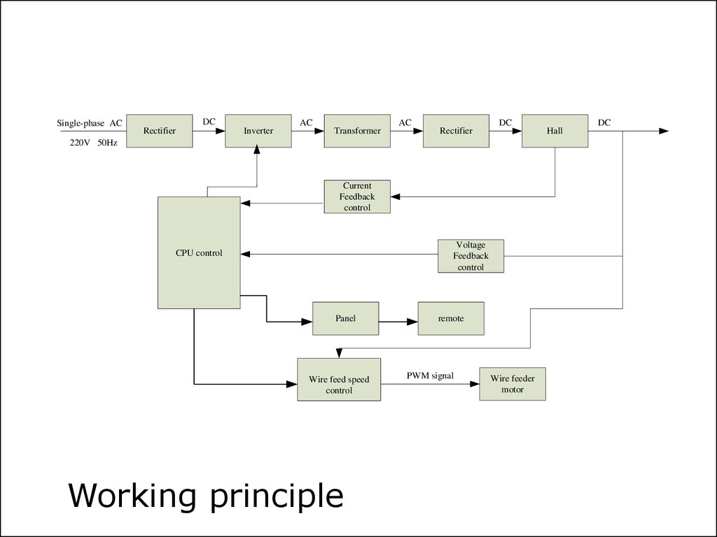
3. 1、Introduction of working principle
4.
Single-phase ACDC
Rectifier
Inverter
AC
Transformer
AC
Rectifier
DC
220V 50Hz
Current
Feedback
control
Voltage
Feedback
control
CPU control
Panel
Wire feed speed
control
Working principle
remote
PWM signal
Wire feeder
motor
Hall
DC
5.
SOFT STARTQD1
ZBYQ
OUT+
OUTQD2
OC1
OC2
-24V
3
AC1
AC
-
4
Motor PCB
GDN
AC
+
2
Switch Power Supply
Fan
Control PCB
NTC
1
GAS
AC2
System chart
6.
7.
No.Name
Code
Unit
1
HANDLE
8.253.020
1
2
LEFT BOARD
8.050.112
1
3
REAR PANEL
8.068.984
1
4
SWITCH
7.232.730
1
5
AIR INLET
8.462.180
1
6
SPARE AND TOOL BOX
8.831.010
1
7
FAN
7.720.005-B
1
8
CLAPBOARD
8.124.623
1
9
MIG EMC BAN
5.496.067
1
10
Y TYPE THREE-WAY CONNECTION
7.624.281
1
11
GAS VALVES MUNTING PLATE
8.123.159-B
1
12
TWO-POSITION SOLENOID VALVE
7.253.013
2
13
TRANSFORMER
6.185.119
1
14
SHORE
8.123.620
1
15
RECTIFIER
7.411.015
2
16
MIG CONTROL PCB
5.496.996-E
1
17
HEAT SINK II
8.425.119
1
18
TRANSISTOR
7.425.631
6
19
HEAT SINK III
8.425.120
1
20
HEXAGON KEEP POST
7.503.530
4
21
MAIN PCB
5.496.068-A
1
22
SHORE
8.123.633
2
23
HALL
7.321.105
1
8.
24DIODE
7.421.107
8
25
NTC HOT RESISTANCE
7.445.401
1
26
CHARFILM POTENTIAL
7.456.126
1
27
HEAT SINK I
8.425.118
1
28
MIG FEDDER POWER
4.021.000
1
29
MIG FACEPLATE
5.495.994-B
1
30
FRONT PANEL
8.069.984
1
31
FRONT BLANKING PLATE
8.306.115
1
32
TRIPLEX AVIATION SOCKET
7.132.303
1
33
TRANSEND NEB
8.178.110
1
34
35 70MM2 SOCKET
7.152.315
1
35
BASE
8.055.118
1
36
CHANGEOVER CONNECTOR
8.462.181
2
37
FEED FIGHT
8.081.110
1
38
FEED PLATE
8.199.130
1
39
RIGHT BOARD
8.051.112
1
40
SQUARENESS BIN
7.686.300
1
41
INDUCTANCE
6.271.132
1
9. 2、Introduction of main circuit(parts different from MMA)
2、Introduction of maincircuit parts different
from MMA
10.
23
4
5
Main Board----Motor circuit
MDV
Drive
R01
R(CMD1)
R08
1
2
7
12
13
VM-2
+01
7
5
3
12
A K
C08
R022
VS0
R016
OC
R017
C04
T02
C07
R015
5
4
8
7
6
9
R033
T04
R13
T03
C03
D04
K01
R012
-S
+S
R12
11
14
E1
E2
CT
GND
R010
N.INV
RT
Feedback
VS
R09
COMP
R05
C02
K
3
10
INV
C1
C2
R04
R(BMD)
2
1
RGP30K
+01
VM-2
MD
D02
5
C01
+24V1
R(CMD2)
A
R02
MDV
T05
U01
SD
R03
VIN
PWM
VREF
+01
15
16
+01
OSC
OK
2
VCC
C024
R07
W02
1
R06
3
VCC
R032
C05
+01
R011
R023
+01
OC
R018
C09
R019
+01
R024
VS0
U02C
+01
U02D
12
14
R025
9
10
+01
Compensate
R030
R027
Input signal
R028
VCC
1
2
U07
A
C
K
E
4
3
R038
7
C044
DGND
R040
+01
U02B
5
+24V1
1
PWM
C097
6
C026
Z2
W05
U03
Vin
Vout
GND
R046
+01
3
VCC
C096
C095
R041
2
PWM1
C010
C012
D19
R039
OK
+01
+01
VS
8
R029
VCC
D03
R026
13
D010
+01
*
OK
Power source
Title
Size
Number
11.
View of main board12.
Photo of main board13.
Photo of main PCBAC
rectifier
Motor driver
circuit
14. 3、Introduction of control circuit(parts different from MMA)
3、Introduction ofcontrol circuit parts
different from MMA
15.
23
4
C71
C34
D17
+15V
R71
R2
IF
R79
-15V
C2
DX
R89
VREF
WV2
2
13
R72
14
R7
R5
U2D
R15
9
U2C
12
3
R73
1
R77
R49
D14
J1B
7
8
7
MIG/CC
5
COMP
T5
DRIVE
Drive T1
Drive T2
MIG/CC
R57
ADDI
5
IF
+15V
OK
R33
R9
C4
C6
D
13
U1D
C17
D10
14
1
2
3
4
5
6
7
R11
12
R43
+24V
Control Board----Wave adjust circuit
Funs
The fan intellectualized working circuit
1
2
2
MIG-IMIN
-15V
R6
PI
Modify
Fan
R129
T3
C
7
R8
1
B
E
MIG-IMIN
OC
U1B
6
C79
C
3
R20
9
+15V
C9
D13
R68
D2
1
C10
C33
R99
10 SP
2
CC
R30
R130
R34
V-
Drive T1
Drive T2
R75
2
CC
C90
Rd
SSt
1
J1A
PPGV
Sd
V+
Tc
C29
OK
W2
C46
R12
R74
D1
C53
21
D16
U2B
5
13
11
14
12
+15V
6
C7
Vc
OUTA
OUTB
R13
4
R4
R47
VREF
Sy nc
OSC
Tr
10
C1
PPGV
R22
8
VCC
VF
16
3
4
6
GND
-15V
WV1
U2A
1
R1
U4
ADDI
11
DY
15
C3
Vmin
R29
C38
R-p
VCC
ZD2
R78
R3
+15V
5
CON2
16.
17.
DriveImax
Imin
Power
CR
Funs
NTCS
IGBT OT
Gun
QF/DY
WVIN
IFB
W2
A
Vmin
PWM
MB
Wvf
18.
• DRIVE--Connected with main board to provide drivesignal for discrete IGBT.
Pin 1---- +15V Pin 2~5---- Drive signal Pin 6---- OC; Pin 7---- GND
• SOURCE--Connected with main board to provide
control board with power source and test signal of tip.
Pin 1---- +24V Pin 2---- GND Pin 3---- -24V.
• MB--Connected with panel board to communicate.
• CR--Connected with crater arc potentiometer, Burn back
signal .
Pin 1---- GND Pin 2---- crater arc Pin 3---- +5V.
• GUN--Connected with the torch to provide signal of gun.
• QF/DY--Connected with the gas switch.
19.
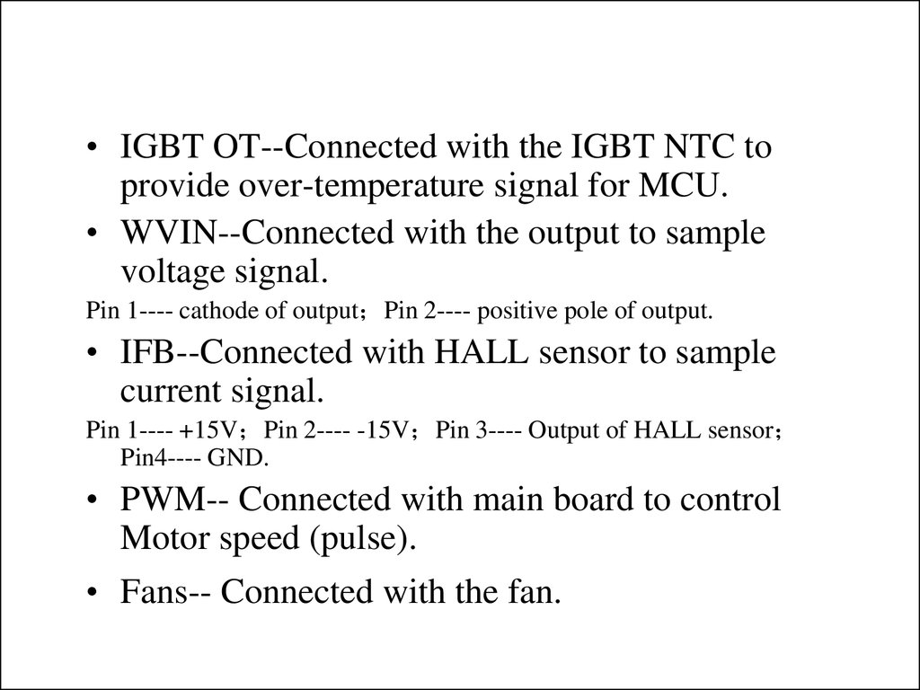
• IGBT OT--Connected with the IGBT NTC toprovide over-temperature signal for MCU.
• WVIN--Connected with the output to sample
voltage signal.
Pin 1---- cathode of output Pin 2---- positive pole of output.
• IFB--Connected with HALL sensor to sample
current signal.
Pin 1---- +15V Pin 2---- -15V Pin 3---- Output of HALL sensor
Pin4---- GND.
• PWM-- Connected with main board to control
Motor speed (pulse).
• Fans-- Connected with the fan.
20.
• Imax—used to adjust maximum weldingcurrent (MMA).
• Imin—used to adjust minimum welding
current (MMA).
• A—used to adjust display current (MMA).
• W2—used to adjust maximum welding
voltage (MIG).
• Vmin—used to adjust minimum voltage
(MIG).
• Wvf —used to adjust display voltage (MIG).
21. 4、Introduction of panel circuit
22.
23
4
Display
ElectricalDigital
drawing
of panel board
Knob
WV2
WV1
WAVE
VCC
C109
VCC
C108
R125
DOWN SLOPE
LED1
C112
R124
Connector
J1
OK
DIN
load
CLK
4T/2T
I/O
MMA
OUT1
MIG
+15V
0.8/1.0
WV2
VGD/DS/AF
WV1
I_Welding
VCC
1
2
3
4
5
6
7
8
9
10
11
12
13
14
15
16
3
C7
1
VCC
3
C8
O1 O2
C1
C2
4 MIG/TIG/MMA
SEGB
LED3
0.6
SEGB LED71
SEGC
LED4
0.8
SEGC LED72
SEGD
LED5
0.9
SEGD LED73
SEGE
LED6
1.0
SEGE LED74
spl
SEGF LED75
R115
10K
DIG6
SEGA LED70
DIG7
SEGF
LED7
2
1
O1 O2
C1
C2
4
4T/2T
SEGG LED76
LED8
3
Display Driver
C10
1
O1 O2
C1
C2
4
4
C2
C1
O2 O1
1
0.8/1.0
OK
3
C110
U13
8
6
7
5
VCC
ORG
DC
GND
93C86
DO
SCK
DI
CS
MAX7221
C12
DIN
CS
CLK
2
VCC
2
C11
MATERIAL
KG1
R116
VRDOFF
SEDP
VRDON
SEDP
2
KG2
C9
OUT1
MIG
MMA
LED2
KG3
R114
10K
A
B
C
D
E
F
G
NC
DP
DIG1
DIG2
DIG3
SEGA
SEGG
VCC
SEGDP
DIG3
DIG4
DIG5
11
7
4
2
1
10
5
6
3
12
9
8
KG4
R113
10K
VCC
CS
MIG/TIG/MMA
MATERIAL
R123
Key
VCC
SEGA
SEGB
SEGC
SEGD
SEGE
SEGF
SEGG
A
B
C
D
E
F
G
NC
DP
DIG1
DIG2
DIG3
I_Welding
C113
R119
SEGDP
DIG0
DIG1
DIG2
CURRENT
VGD/DS/AF
VCC
U14 voltage display
U15 Ampere display
11
7
4
2
1
10
5
6
3
12
9
8
SEGA
SEGB
SEGC
SEGD
SEGE
SEGF
SEGG
4
2
3
1
I/O
C13
DIG0
DIG1
DIG2
DIG3
DIG4
DIG5
DIG6
DIG7
1
12
13
2
11
6
7
3
10
5
8
24
4
U12
DIN
VCC
CS
CLK
ISET
DIG0
SEG A
DIG1
SEG B
DIG2
SEG C
DIG3
SEG D
DIG4
SEG E
DIG5
SEG F
DIG6
SEG G
DIG7
DOUT SEG DP
GND
GND
VCC
19
18
14
16
20
23
21
15
17
R117
SEGA
SEGB
SEGC
SEGD
SEGE
SEGF
SEGG
22 SEGDP
9
23.
View of panel board24.
Photo of panel board25.
5、TroubleshootingSeries A: Troubles about panel display
Series B: Troubles about power system
26.
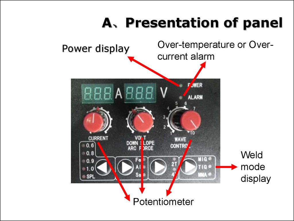
A、Presentation of panelPower display
Over-temperature or Overcurrent alarm
Weld
mode
display
Potentiometer
27.
B、 Presentation of wire-feederMotor drive circuit In Main PCB
WD5--Max speed adjust
Between the two
Pins, is CPU speed
Voltage
A
WD2--Min speed adjust
B(U02-6P)
E/F/G wave point is
the IC 1/2/3 P
Between the two
Pins, is Motor
voltage
Drive transistor
C
Motor circuit GND
(common point )
D
28.
Test point wavePoint A wave :The PWM wave from digital control PCB
29. Point B wave :The PWM set point from 6P of U02
Point D wave :The MOSFET gate drive PWMPoint C wave :The drive PWM from SG3524 11P
Point E wave : U01 SG3524 1P
30. Point F wave : U01 SG3524 2P
Point G wave :U01 SG3524 3P31.
Wirefeederdoesn’t
work
Fan don’t
work
No gas
Wire reel
doesn’t
work
Motor damaged
Check and change it
Control circuit damaged
May be the MOS or DIODE in
the board is damaged, check it
according to the above
information.
Wire reel
works
The press wheel is loosen
or weld wire skids
Press it tightly again
The wheel doesn’t fit with
the diameter of weld wire
Change the wheel
Wire reel damaged
Change it
Wire feed pipe or tip is
jammed
Repair or change it
According to page16, check the socket
Funs, there isn’t +24V,
Check +24V power source and
whether the socket link is good.
If there is +24V,check netlabel Fan ,
there isn’t 5V.
Change control PCB
If there is +5V,check T3, there isn’t
0.7V between B and E.
Change T3
reference to 170HF
32. List of spare part
TitleUnit
Hall
1
Rectifier
1
MIG panel
1
MIG sole plate
1
NTC
1
Waterproof switch
1
Control PCB
1
Wire feed frame
1
Plastic front panel
1
Plastic rear panel
1
Insulated potentiometer
3