


 Механика
Похожие презентации:


 Application Model")
Influence of supply voltage on torque–speed curve
1. Lecture 3
2.
3.
Table of synchronous speed of rotation of induction motors as afunction of frequency and number of poles
Rotational speed of induction motor, rev/min
Frequency, Hz
number of pole pairs
4. Influence of supply voltage on torque–speed curve
We established earlier that at any given slip, the air-gap fluxdensity is proportional to the applied voltage, and the induced current in
the rotor is proportional to the flux density. The torque, which depends
on the product of the flux and the rotor current, therefore depends on the
square of the applied voltage. This means that a comparatively modest
fall in the voltage will result in a much larger reduction in torque
capability, with adverse effects which may not be apparent to the unwary
until too late.
5.
To illustrate the problem, consider the torque–speed curves for acage motor shown in Figure. The curves (which have been expanded to
focus attention on the low-slip region) are drawn for full voltage (100%),
and for a modestly reduced voltage of 90%. With full voltage and
fullload torque the motor will run at point X, with a slip of say 5%. Since
this is the normal full-load condition, the rotor and stator currents will be
at their rated values.
6.
Now suppose that the voltage falls to 90%. The load torque isassumed to be constant so the new operating point will be at Y. Since the
air-gap flux density is now only 0.9 of its rated value, the rotor current
will have to be about 1.1 times rated value to develop the same torque, so
the rotor e.m.f. is required to increase by 10%. But the flux density has
fallen by 10%, so an increase in slip of 20% is called for. The new slip is
therefore 6%.
7.
The drop in speed from 95% of synchronous to 94% may wellnot be noticed, and the motor will apparently continue to operate quite
happily. But the rotor current is now 10% above its rated value, so the
rotor heating will be 21% more than is allowable for continuous running.
The stator current will also be above rated value, so if the motor
is allowed to run continuously, it will overheat. This is one reason why
all large motors are fitted with protection, which is triggered by over
temperature. Many small and medium motors do not have such
protection, so it is important to guard against the possibility of under
voltage operation.
8. Speed control
We have seen that to operate efficiently an induction motor mustrun with a small slip. It follows that any efficient method of speed
control must be based on varying the synchronous speed of the Weld,
rather than the slip. The two factors that determine the speed of the field,
are the supply frequency and the pole number
Tem J m
d m
B m TL
dt
The pole number has to be an even integer, so where
continuously adjustable speed control over a wide range is called for, the
best approach is to provide a variable-frequency supply. In this chapter
we are concerned with constant frequency mains operation, so we have a
choice between pole-changing, which can provide discrete speeds only,
or slip control which can provide continuous speed control, but is
inherently inefficient.
9. Pole-changing motors
For some applications continuous speed control may be anunnecessary luxury, and it may be sufficient to be able to run at two
discrete speeds. Among many instances where this can be acceptable and
economic are pumps, lifts and hoists, fans and some machine tool drives.
Previously we established that the pole number of the Weld was
determined by the layout and interconnection of the stator coils, and that
once the winding has been designed, and the frequency specified, the
synchronous speed of the Weld is fixed. If we wanted to make a motor,
that could run at either of two different speeds, we could construct it with
two separate stator windings (say 4-pole and 6-pole), and energise the
appropriate one. There is no need to change the cage rotor since the
pattern of induced currents can readily adapt to suit the stator pole
number. Early 2-speed motors did have 2 distinct stator windings, but
were bulky and inefficient.
10.
It was soon realised that if half of the phase belts within eachphase winding could be reversed in polarity, the eVective pole number
could be halved. For example, a 4-pole MMF pattern (N-S-N-S) would
become (N-N-S-S), i.e. effectively a 2-pole pattern with one large N pole
and one large S pole. By bringing out six leads instead of three, and
providing switching contactors to effect the reversal, two discrete speeds
in the ratio 2:1 are therefore possible from a single winding. The
performance at the high (e.g. 2-pole) speed is relatively poor, which is
not surprising in view of the fact that the winding was originally
optimised for 4-pole operation.
11.
It was not until the advent of the more sophisticated poleamplitude modulation (PAM) method in the 1960s that 2-speed singlewinding high-performance motors with more or less any ratio of speeds
became available from manufacturers. This subtle technique allows close
ratios such as 4/6, 6/8, 8/10 or wide ratios such as 2/24 to be achieved.
Close ratios are used in pumps and fans, while wide ratios are used for
example in washing machines where a fast spin is called for.
12.
The beauty of the PAM method is that it is not expensive. Thestator winding has more leads brought out, and the coils are connected to
form non-uniform phase belts, but otherwise construction is the same as
for a single-speed motor. Typically six leads will be needed, three of
which are supplied for one speed, and three for the other, the switching
being done by contactors. The method of connection (star or delta) and
the number of parallel paths within the winding are arranged so that the
air-gap flux at each speed matches the load requirement. For example, if
constant torque is needed at both speeds, the flux needs to be made the
same, whereas if reduced torque is acceptable at the higher speed the flux
can obviously be lower.
13. Voltage control of high-resistance cage motors
Where efficiency is not of paramount importance, the torque (andhence the running speed) of a cage motor can be controlled simply by
altering the supply voltage. The torque at any slip is approximately
proportional to the square of the voltage, so we can reduce the speed of
the load by reducing the voltage. The method is not suitable for standard
low-resistance cage motors, because their stable operating speed range is
very restricted, as shown in Figure
14.
But if special high-rotor resistance motors are used, the slope ofthe torque–speed curve in the stable region is much less, and a rather
wider range of steady-state operating speeds is available, as shown in
Figure
The most unattractive feature of this method is the low efficiency, which is
inherent in any form of slip control. fierecall that the rotor efficiency at slip s is
( 1 s ), so if we run at say 70% of synchronous speed (i.e. s = 0.3), 30% of the power
crossing the air-gap is wasted as heat in the rotor conductors. The approach is therefore
only practicable where the load torque is low at low speeds, so that at high slips the heat
in the rotor is tolerable. A fan-type characteristic is suitable, as shown in Figure, and
many ventilating systems therefore use voltage control.
15.
Voltage control became feasible only when relatively cheapthyristor a.c. voltage regulators arrived on the scene during the 1970s.
Previously the cost of autotransformers or induction regulators to obtain
the variable voltage supply was simply too high. The thyristor hardware
required is essentially the same as discussed earlier for soft starting, and
a single piece of kit can therefore serve for both starting and speed
control. Where accurate speed control is needed, a tachogenerator must
be fitted to the motor to provide a speed feedback signal, and this
naturally increases the cost significantly.
Applications are numerous, mainly in the range 0.5–10 kW, with
most motor manufacturers offering high-resistance motors specifically
for use with thyristor regulators.
16. Speed control of wound-rotor motors
The fact that the rotor resistance can be varied easily allows us tocontrol the slip from the rotor side, with the stator supply voltage and
frequency constant. Although the method is inherently inefficient it is
still used in many medium and large drives such as hoists, conveyors and
crushers because of its simplicity and comparatively low cost.
A set of torque–speed characteristics is shown in Figure, from
which it should be clear that by appropriate selection of the rotor circuit
resistance, any torque up to typically 1.5 times full-load torque can be
achieved at any speed.
17. Torque–speed characteristics – constant v/f operation
When the voltage at each frequency is adjusted so that the ratioV/f is kept constant up to base speed, and full voltage is applied
thereafter, a family of torque–speed curves as shown in Figure is
obtained. These curves are typical for a standard induction motor of
several kW output.
18.
As expected, the no-load speeds are directly proportional to thefrequency, and if the frequency is held constant, e.g. at 25 Hz in Figure,
the speed drops only modestly from no-load (point a) to full-load (point
b). These are therefore good open-loop characteristics, because the speed
is held fairly well from no-load to full-load. If the application calls for
the speed to be held precisely, this can clearly be achieved (with the aid
of closed-loop speed control) by raising the frequency so that the fullload operating point moves to point (c).
19.
We also note that the pull-out torque and the torque stiffness (i.e.the slope of the torque–speed curve in the normal operating region) is
more or less the same at all points below base speed, except at low
frequencies where the effect of stator resistance in reducing the flux
becomes very pronounced. It is clear from Figure that the starting torque
at the minimum frequency is much less than the pullout torque at higher
frequencies, and this could be a problem for loads which require a high
starting torque.
20.
The low-frequency performance can be improved by increasingthe V/f ratio at low frequencies in order to restore full flux, a technique
which is referred to as ‘low-speed voltage boosting’. Most drives
incorporate provision for some form of voltage boost, either by way of a
single adjustment to allow the user to set the desired starting torque, or
by means of more complex provision for varying the V/f ratio over a
range of frequencies. A typical set of torque–speed curves for a drive
with the improved low-speed torque characteristics obtained with voltage
boost is shown in Figure
21.
The curves in Figure have an obviousappeal because they indicate that the motor is
capable of producing practically the same
maximum torque at all speeds from zero up to
the base (50 Hz or 60 Hz) speed.
This region of the characteristics is known
as the ‘constant torque’ region, which means that
for frequencies up to base speed, the maximum
possible torque which the motor can deliver is
independent of the set speed. Continuous operation
at peak torque will not be allowable because the
motor will overheat, so an upper limit will be
imposed by the controller, as discussed shortly. With
this imposed limit, operation below base speed
corresponds to the armature-voltage control region
of a d.c. drive, as exemplified in Figure
22.
We should note that the availability of high torque at low speeds(especially at zero speed) means that we can avoid all the ‘starting’
problems associated with fixed-frequency operation. By starting off
with a low frequency which is then gradually raised the slip speed of
the rotor is always small, i.e. the rotor operates in the optimum
condition for torque production all the time, thereby avoiding all the
disadvantages of high-slip (low torque and high current) that are
associated with mains-frequency starting. This means that not only can
the inverter-fed motor provide rated torque at low speeds, but – perhaps
more importantly – it does so without drawing any more current from
the mains than under full-load conditions, which means that we can
safely operate from a weak supply without causing excessive voltage
dips. For some essentially fixed-speed applications, the superior starting
ability of the inverter-fed system alone may justify its cost.
23.
Beyond the base frequency, the V/f ratio reduces because Vremains constant. The amplitude of the flux wave therefore reduces
inversely with the frequency. The pull-out torque always occurs at the
same absolute value of slip speed, and that the peak torque is
proportional to the square of the flux density. Hence in the constant
voltage region the peak torque reduces inversely with the square of the
frequency and the torque–speed curve becomes less steep, as shown in
Figure.
Although the curves in Figure show what torque the motor can
produce for each frequency and speed, they give no indication of
whether continuous operation is possible at each point, yet this matter is
of course extremely important from the user’s viewpoint, and is
discussed next.
24. Modelling the electromechanical energy conversion process
The behaviour of the motor was determined primarily by the slip.In particular we saw that if the motor was unloaded, it would settle at
almost the synchronous speed (i.e. with a very small slip), with very little
induced rotor current, at very low frequency. As the load torque was
increased the rotor slowed relative to the travelling flux; the magnitude
and frequency of the induced rotor currents increased; the rotor thereby
produced more torque; and the stator current and power drawn from the
supply automatically increased to furnish the mechanical output power.
25.
A very important observation in relation to what we are nowseeking to do is that we recognised earlier that although the rotor
currents were at slip frequency, their effect (i.e. their MMF) was always
reflected back at the stator windings at the supply frequency. This
suggests that it must be possible to represent what takes place at slipfrequency on the rotor by referring the action to the primary (fixedfrequency) side, using a transformer-type model; and it turns out that
we can indeed model the entire energy-conversion process in a very
simple way. All that is required is to replace the referred rotor resistance
( R2 ) with a fictitious slip-dependent resistance ( R2 s ) in the shortcircuited secondary of our transformer equivalent circuit.
26.
Hence if we build from the exact transformer circuit, we obtainthe induction motor equivalent circuit shown in Figure
‘Exact’ per-phase equivalent circuit of induction motor.
The secondary (rotor) parameters have been referred to the primary
(stator) side
27.
At any given slip, the power delivered to this ‘load’ resistancerepresents the power crossing the air-gap from rotor to stator. We can see
straightaway that because the fictitious load resistance is inversely
proportional to slip, it reduces as the slip increases, thereby causing the
power across the air-gap to increase and resulting in more current and
power being drawn in from the supply. This behaviour is of course in line
with what we already know about the induction motor.
We will see how to use the equivalent circuit to predict and
illuminate motor behaviour in the next section, but first there are two
points worth making.
28.
Firstly, given the complexity of the spatial and temporalinteractions in the induction motor it is extraordinary that everything can
be properly represented by such a simple equivalent circuit.
Secondly, the following brief discussion is offered for the benefit
of readers who are seeking at least some justification for introducing the
fictitious resistance , though it has to be admitted that full treatment is
beyond our scope.
29.
The key to developing the representation lies in ensuring that themagnitude and phase of the referred rotor current (at supply frequency)
in the transformer model is in agreement with the actual current (at slip
frequency) in the rotor. The induced e.m.f. in the rotor at slip s would be
sE2 at frequency sf , where E2 is the e.m.f. induced under locked rotor
(s = 1) conditions, when the rotor frequency is the same as the supply
frequency, i.e. f. This e.m.f. acts on the series combination of the rotor
resistance R2 and the rotor leakage reactance, which at frequency sf is
given by sX 2 , where X 2 is the rotor leakage reactance at supply
frequency. Hence the magnitude of the rotor current is given by
I2
sE2
R22 s 2 X 22
30.
In the supply-frequency equivalent circuit, e.g. Figure,the secondary e.m.f. is E2 , rather than sE2 , so to obtain the same
current in this model as given by equation
I2
sE2
R22 s 2 X 22
we require the slip-frequency rotor resistance and reactance to be divided
by s, in which case the secondary current would be correctly given by
I2
E2
2
R2 X 2
s
sE2
R22 s 2 X 22
31. Limitations imposed by the inverter – constant power and constant torque regions
The main concern in the inverter is to limit the currents to a safevalue as far as the main switching devices are concerned. The current
limit will be at least equal to the rated current of the motor, and the
inverter control circuits will be arranged so that no matter what the user
does the output current cannot exceed a safe value.
32.
The current limit feature imposes an upper limit on thepermissible torque in the region below base speed. This will normally
correspond to the rated torque of the motor, which is typically about half
the pull-out torque, as indicated by the shaded region in Figure
33.
In the region below base speed, the motor can therefore developany torque up to rated value at any speed (but not necessarily for
prolonged periods, as discussed below). This region is therefore known
as the ‘constant torque’ region, and it corresponds to the armature voltage
control region of a d.c. drive.
Above base speed of the flux is reduced inversely with the
frequency; because the stator (and therefore rotor) currents are limited,
the maximum permissible torque also reduces inversely with the speed,
as shown in Figure. This region is therefore known as the ‘constant
power’ region. There is of course a close parallel with the d.c. drive here,
both systems operating with reduced or weak Weld in the constant power
region. The region of constant power normally extends to somewhere
around twice base speed, and because the flux is reduced the motor has
to operate with higher slips than below base speed to develop the full
rotor current and torque.
34.
At the upper limit of the constant power region, the current limitcoincides with the pull-out torque limit. Operation at still higher speeds
is sometimes provided, but constant power is no longer available because
the maximum torque is limited to the pull-out value, which reduces
inversely with the square of the frequency. In this high-speed motoring
region (Figure), the limiting torque–speed relationship is similar to that
of a series d.c. motor.
35. Generating and braking
Having explored the torque–speed curve for the normal motoringregion, where the speed lies between zero and just below synchronous,
we must ask what happens if the speed is above the synchronous speed,
or is negative.
A typical torque–speed curve for a cage motor covering the full
range of speeds, which are likely to be encountered in practice, is shown
in Figure
36.
37.
38.
39.
40.
We can see from Figure that the decisive [diˈsīsiv] factor as far asthe direction of the torque is concerned is the slip, rather than the speed.
When the slip is positive the torque is positive, and vice versa. The
torque therefore always acts so as to urge the rotor to run at zero slip, i.e.
at the synchronous speed. If the rotor is tempted to run faster than the
Weld it will be slowed down, whilst if it is running below synchronous
speed it will be urged to accelerate forwards. In particular, we note that
for slips greater than 1, i.e. when the rotor is running backwards (i.e. in
the opposite direction to the Weld), the torque will remain positive, so
that if the rotor is unrestrained it will first slow down and then change
direction and accelerate in the direction of the field.
41.
42. Injection braking
This is the most widely used method of electrical braking. Whenthe ‘stop’ button is pressed, the 3-phase supply is interrupted, and a d.c.
current is fed into the stator via two of its terminals. The d.c. supply is
usually obtained from a rectifier fed via a low-voltage high-current
transformer.
We saw earlier that the speed of rotation of the air-gap Weld is
directly proportional to the supply frequency, so it should be clear that
since d.c. is effectively zero frequency, the air-gap Weld will be
stationary. We also saw that the rotor always tries to run at the same
speed as the Weld. So, if the Weld is stationary, and the rotor is not, a
braking torque will be exerted.
42
43.
A typical torque–speed curve for braking a cage motor is shownin Figure, from which we see that the braking (negative) torque falls to
zero as the rotor comes to rest.
43
44.
This is in line with what we would expect, since there will beinduced currents in the rotor (and hence torque) only when the rotor is
‘cutting’ the flux. As with plugging, injection (or dynamic) braking is a
dissipative process, all the kinetic energy being turned into heat inside
the motor.
44
45. Plug reversal and plug braking
Because the rotor always tries to catch up with the rotating Weld,it can be reversed rapidly simply by interchanging any two of the supply
leads. The changeover is usually obtained by having two separate 3-pole
contactors, one for forward and one for reverse. This procedure is known
as plug reversal or plugging, and is illustrated in Figure
45
46.
The motor is initially assumed to be running light (and thereforewith a very small positive slip) as indicated by point A on the dotted
torque–speed curve in Figure
Two of the supply leads are then reversed, thereby reversing the
direction of the Weld, and bringing the mirror-image torque–speed curve
shown by the solid line into play. The slip of the motor immediately after
reversal is approximately 2, as shown by point B on the solid curve. The
torque is thus negative, and the motor decelerates, the speed passing
through zero at point C and then rising in the reverse direction before
settling at point D, just below the synchronous speed.
46
47.
The speed–time curve is shown in FigureWe can see that the deceleration (i.e. the gradient of the speed–
time graph) reaches a maximum as the motor passes through the peak
torque (pullout) point, but thereafter the final speed is approached
gradually, as the torque tapers down to point D.
47
48.
Very rapid reversal is possible using plugging; for example a 1kW motor will typically reverse from full speed in under 1 s . But large
cage motors can only be plugged if the supply can withstand the very
high currents involved, which are even larger than when starting from
rest. Frequent plugging will also cause serious overheating, because each
reversal involves the ‘dumping’ of four times the stored kinetic energy as
heat in the windings.
Plugging can also be used to stop the rotor quickly, but obviously
it is then necessary to disconnect the supply when the rotor comes to rest,
otherwise it will run-up to speed in reverse. A shaft-mounted
reverserotation detector is therefore used to trip out the reverse contactor
when the speed reaches zero.
48
49.
We should note that, whereas, in the regenerative mode(discussed in the previous section) the slip was negative, allowing
mechanical energy from the load to be converted to electrical energy and
fed back to the mains, plugging is a wholly dissipative process in which
all the kinetic energy ends up as heat in the motor.
49
50. Stepping motors
Stepping motors are attractive because they can be controlleddirectly by computers or microcontrollers. Their unique feature is that
the output shaft rotates in a series of discrete angular intervals, or steps,
one step being taken each time a command pulse is received. When a
definite number of pulses has been supplied, the shaft will have turned
through aknownangle, and this makes the motor ideally suited for openloop position control.
50
51. Performance Features of MOONS' Stepping Motors
• Accurate Position ControlThe number of control pulses defines the motor shaft position.
Position error is very small (less than 1/10th of a degree), and non
cumulative.
• Precise Motor Speed
Step motor running speed, is exactly determined by the frequency
of the control pulses. Because the speed is very precise and easy to
control, step motors are often used where coordinated motion control is
needed.
51
52.
• Forward & Reverse, Pause and Holding FunctionMotor torque and position control is effective throughout the
entire speed range, including zero speed holding torque. The zero speed
holding torque locks the shaft at the desired position to hold the load in
place.
• Low Speed Operation
Step motors produce a large amount of torque, and are easy to
control, at low speeds. This often eliminates the need for speed reduction
gearboxes, reduces costs and saves space.
• Long Life
The brushless design of step motors leads to motors with a very
long life. Step motor life is usually determined by the life of the bearings.
52
53. Basic Structure and Motor Operation
5354.
A basic stepping motor system is shown in FigureThe drive contains the electronic switching circuits, which supply
the motor, and is discussed later. The output is the angular position of the
motor shaft, while the input consists of two low-power digital signals.
Every time a pulse occurs on the step input line, the motor takes one
step, the shaft remaining at its new position until the next step pulse is
supplied. The state of the direction line (‘high’ or ‘low’) determines
whether the motor steps clockwise or anticlockwise. A given number of
step pulses will therefore cause the output shaft to rotate through a
definite angle.
54
55.
This one to one correspondence between pulses and steps is thegreat attraction of the stepping motor: it provides position control,
because the output is the angular position of the output shaft. It is a
digital system, because the total angle turned through is determined by
the number of pulses supplied; and it is open-loop because no feedback
need be taken from the output shaft.
55
56. Technical Data and Terminology
• Load CalculationsA. Torque load (Tf)
Tf = G * r
G: weight
r: radius
B. Inertia load (TJ)
TJ = J * dw/dt
J = M * (R12+R22 ) / 2 (Kg * cm)
M: mass
R1: outside radius
R2: inside radius
dw/dt: angle acceleration
56
57.
• Speed-Torque CharacteristicsThe dynamic torque curve is an important aspect of stepping
motor’s output performance.
The followings are some keyword explanations.
1. Working frequency point express the stepping motors
rotational speed value at this point
n = q * Hz / (360 * D)
n: rev/sec
Hz: the frequency value at this point
D: the subdividing value of motor driver
q: the step angle of stepping motor
E.g.: 1.8° stepping motor, in the condition of I/2 subdividing
(each step 0.9°) runs at 500Hz its speed is 1.25r/s.
57
58.
5859.
Борьба с нежелательными явлениямиЗазор между роторными и статорными зубцами всегда
делается минимальным для увеличения жесткости фиксации. Сама
точность позиционирования зависит от характеристик только лишь
инвертора, так как прочие факторы на нее влияют в гораздо
меньшей степени. А сейчас необходимо рассмотреть ряд важных
характеристик и понятий, таких, как максимальный статический
момент, положения «мертвого» ротора, а также точность
позиционирования всех этих положений. Для определения
вышеперечисленных терминов существует сразу две общепринятых
распространенных концепции.
59
60.
2. Start/Stop region: the region in which a stepping motor canbe directly started or stopped (Область, в которой шаговый двигатель
может быть непосредственно запущен или остановлен).
3. Detent Torque: The maximum torque that can be applied to
the shaft of a non-energized motor without causing rotation.
4. Speed-Torque Curve: The speed-torque characteristics of a
stepping motor are a function of the drive circuit, excitation method and
load inertia.
5. Maximum Slew Frequency: The maximum rate at which the
step motor will run and remain in synchronism.
6. Maximum Starting Frequency: The maximum pulse rate
(frequency) at which an unloaded step motor can start and run without
missing steps or stop without missing steps.
60
61.
7. Pull-in Torque: the maximum dynamic torque value that astepping motor can load directly at the particular operating frequency
point.
8. Pull-out Torque: the maximum dynamic torque value that a
stepping motor can load at the particular operating frequency point when
the motor has been started. Because of the inertia of rotation the PullOut. Torque is always larger than the Pull-In Torque.
9. Slewing Range This is the area between the pull-in and pullout torque curves where a step motor can run without losing step, when
the speed is increased or decreased gradually. Motor must be brought up
to the slew range with acceleration and deceleration technique known as
ramping.
61
62.
10. Accuracy: This is defined as the difference between thetheoretical and actual rotor position expressed as a percentage of the step
angle. Standard is ±5%. An accuracy of ±3% is available on special
request. This positioning error is noncumulative. Accuracy This is
defined as the difference between the theoretical and actual rotor position
expressed as a percentage of the step angle. Standard is ±5%. An
accuracy of ±3% is available on special request. This positioning error is
noncumulative.
62
63.
11. Hysteresis Error This is the maximum accumulated errorfrom theoretical position for both forward and backward direction of
rotation.
63
64.
12. Resonance: A step motor operates on a series of input pulses,each pulse causing the rotor to advance one step. In this time the motor’s
rotor must accelerate and then decelerate to a stop. This causes
oscillation, overshoot and vibration. There are some speeds at which the
motor will not run. This is called its resonant frequency. The objective is
to design the system so that no resonant frequencies appear in the
operating speed range. This problem can be eliminated by means of
using mechanical dampers, external electronics, drive methods and step
angle changes.
64
65.
Динамические характеристикиДинамическими характеристиками называются
характеристики двигателя во время движения либо в его начале.
Характеристики пускового момента определяются
диапазоном значений момента сопротивления нагрузки, в котором
двигатель может запускаться и останавливаться без потери шага для
различных частот в наборе импульсов (их около 100). Причина, по
которой используется слово "диапазон", а не "максимум",
заключается в том, что двигатель не способен запускаться или
поддерживать нормальное вращение при малых нагрузках
сопротивления в определенных диапазонах частот, как показано на
рисунке
65
66.
(В некоторой литературеприводится упрощенная
характеристика)
Динамические характеристики: 1 - удерживающий момент; 2 максимальный пусковой момент; 3 — выходной момент; 4 —
максимальная частота вращения; 5 - максимальная пусковая
частота; 6 - область запуска; 7 - область нестабильности; 8 - область
неподвижности ротора.
66
67.
Максимальный статический эффект имеет сразу дваположения:
- Удерживающий. Это максимально допустимый эффект,
который теоретически может быть приложен к валу уже
возбужденного шагового двигателя без возникновения движения
(или крутящий момент при остановленном двигателе. При этом у
двигателя должны быть запитаны две фазы номинальным током).
- Фиксирующий. Соответственно, это также максимальный
статический эффект, который теоретически может быть приложен к
валу невозбужденного двигателя без возникновения последующего
вращения. Чем удерживающий момент выше, тем ниже вероятность
возникновения погрешностей позиционирования, вызываемых
непрогнозируемой нагрузкой (отказали конденсаторы для
электродвигателей, например). Полный фиксирующий момент
возможен только в тех моделях двигателей, в которых используются
постоянные магниты.
67
68.
«Мертвые» положения ротораСуществует сразу три положения, в которых ротор полностью
останавливается:
- Положение равновесия. В нем происходит полная
остановка возбужденного шагового двигателя.
- Фиксация. Также состояние, в котором останавливается
ротор. Но используется это понятие только в отношении тех
двигателей, у которых в конструкции имеется постоянный магнит.
В современных моделях шаговых двигателей, которые
соответствуют всем нормам экологической и энергетической
безопасности, при остановке ротора полностью обесточивается и
обмотка.
68
69.
Во всех случаях, когда рассчитывается либо измеряетсяпусковой момент, необходимо также четко определить схему
управления, метод измерения, способ стыковки и момент инерции,
отнесенный к валу ШД. Как правило, диапазон пусковых значений
момента понижается с ростом момента инерции.
Характеристики выходного момента иначе называются
характеристиками в движении. После того, как выбранный
двигатель запустился при определенном управлении,
обеспечивающем заданный способ возбуждения в пусковом
диапазоне, частота импульсов постепенно возрастает. При
некоторой частоте двигатель выпадает из синхронизма. Взаимосвязь
между моментом сопротивления нагрузки и максимальной частотой
импульсов, при которой сохраняется синхронизм, называется
выходной характеристикой (рисунок). Кривая выходной
характеристики зависит от схемы управления, способа стыковки,
измерительных приборов и других условий.
69
70.
Максимальная частота приемистости определяется какмаксимальная управляющая частота, при которой ненагруженный
двигатель может запускаться и останавливаться без пропуска шагов.
Максимальная выходная частота вращения определяется
как максимальная (шаговая) частота вращения, при которой
ненагруженный двигатель может двигаться без пропуска шагов.
Максимальный пусковой момент определяется как
максимальный момент сопротивления нагрузки, с которой двигатель
может запускаться и сохранять синхронность при наборе импульсов
с частотой до 10 Гц.
70
71. Principle of motor operation
The principle on which stepping motors are based is very simple.When a bar of iron or steel is suspended so that it is free to rotate in a
magnetic field, it will align itself with the field. If the direction of the
field is changed, the bar will turn until it is again aligned, by the action of
the so-called reluctance torque. (The mechanism is similar to that of a
compass needle, except that if a compass had an iron needle instead of a
permanent magnet it would settle along the earth’s magnetic field but it
might be rather slow and there would be ambiguity between N and S!)
71
72.
Before exploring constructional details, it is worth saying a littlemore about reluctance torque, and its relationship with the torqueproducing mechanism we have encountered so far in this book. The alert
reader will be aware that, until this chapter, there has been no mention of
reluctance torque, and might therefore wonder if it is entirely different
from what we have considered so far.
72
73.
The answer is that in the vast majority of electrical machines,from generators in power stations down to induction and d.c. motors,
torque is produced by the interaction of a magnetic field (produced by
the stator windings) with current-carrying conductors on the rotor. We
based our understanding of how d.c. and induction motors produce
torque on the simple formula F BIl for the force on a conductor of
length l carrying a current I perpendicular to a magnetic flux density B.
There was no mention of reluctance torque because (with very few
exceptions) machines which exploit the ‘BIl’ mechanism do not have
reluctance torque.
73
74.
As mentioned above, reluctance torque originates in the tendencyof an iron bar to align itself with magnetic Weld: if the bar is displaced
from its alignment position it experiences a restoring torque. The rotors
of machines that produce torque by reluctance action are therefore
designed so that the rotor iron has projections or ‘poles’ (Figure) that
align with the magnetic Weld produced by the stator windings.
74
75.
All the torque is then produced by reluctance action, because withno conductors on the rotor to carry current, there is obviously no ‘BIl’
torque. In contrast, the iron in the rotors of d.c. and induction motors is
(ideally) cylindrical, in which case there is no ‘preferred’ orientation of
the rotor iron, i.e. no reluctance torque.
75
76.
Because the two torque-producing mechanisms appear to beradically different, the approaches taken to develop theoretical models
have also diverged. As we have seen, simple equivalent circuits are
available to allow us to understand and predict the behaviour of
mainstream ‘BIl’ machines such as d.c. and induction motors, and this is
fortunate because of the overwhelming importance of these machines.
Unfortunately, no such simple treatments are available for stepping and
other reluctance-based machines. Circuit-based numerical models for
performance prediction are widely used by manufacturers but they are
not really of much use for illuminating behaviour, so we will content
ourselves with building up a picture of behaviour from a study of typical
operating characteristics.
76
77.
The two most important types of stepping motor are the variablereluctance (VR) type and the hybrid type. Both types utilise the
reluctance principle, the difference between them lying in the method by
which the magnetic Welds are produced. In the VR type the Welds are
produced solely by sets of stationary current-carrying windings. The
hybrid type also has sets of windings, but the addition of a permanent
magnet (on the rotor) gives rise to the description ‘hybrid’ for this type of
motor. Although both types of motor work on the same basic principle, it
turns out in practice that the VR type is attractive for the larger step
angles (e.g. 15 , 30 , 45 ), while the hybrid tends to be best suited when
small angles (e.g. 1.8 , 2.5 ) are required.
77
78. Motor characteristics
Static torque–displacement curvesFrom the previous discussion, it should be clear that the shape of
the torque–displacement curve, and in particular the peak static torque,
will depend on the internal electromagnetic design of the rotor. In
particular the shapes of the rotor and stator teeth, and the disposition of
the stator windings (and permanent magnet(s)) all have to be optimised
to obtain the maximum static torque.
78
79.
We now turn to a typical static torque–displacement curve, andlook at how it determines motor behaviour. Several aspects will be
discussed, including the explanation of basic stepping (which has already
been looked at in a qualitative way); the influence of load torque on step
position accuracy; the effect of the amplitude of the winding current; and
half-step and mini-stepping operation. For the sake of simplicity, the
discussion will be based on the 30 per step 3-phase VR motor
introduced earlier, but the conclusions reached apply to any stepping
motor.
79
80.
Typical static torque–displacement curves for a 3-phase 30 perstep VR motor are shown in Figure
These show the torque that has to be applied to move the rotor
away from its aligned position. Because of the rotor–stator symmetry,
the magnitude of the restoring torque when the rotor is displaced by a
given angle in one direction is the same as the magnitude of the
restoring torque when it is displaced by the same angle in the other
direction, but of opposite sign.
80
81.
There are three curves, one for each of the three phases, and foreach curve we assume that the relevant phase winding carries its full
(rated) current. If the current is less than rated, the peak torque will be
reduced, and the shape of the curve is likely to be somewhat different.
The convention used is that a clockwise displacement of the rotor
corresponds to a movement to the right, while a positive torque tends to
move the rotor anticlockwise.
81
82.
When only one phase, say A, is energised, the other two phasesexert no torque, so their curves can be ignored and we can focus
attention on the solid line in Figure. Stable equilibrium positions (for
phase A excited) exist at = 0 , 90 , 180 and 270 . They are stable
(step) positions because any attempt to move the rotor away from them is
resisted by a counteracting or restoring torque. These points correspond
to positions where successive rotor poles (which are 90 apart) are
aligned with the stator poles of phase A, as shown in Figure.
82
83.
There are also four unstable equilibrium positions, (at = 45 ,135 , 225 and 315 ) at which the torque is also zero. These correspond
to rotor positions where the stator poles are midway between two rotor
poles, and they are unstable because if the rotor is deflected slightly in
either direction, it will be accelerated in the same direction until it
reaches the next stable position. If the rotor is free to turn, it will
therefore always settle in one of the four stable positions.
83
84.
The characteristic of static (holding) torque - displacement is bestexplained using an electro-magnet and a single pole rotor. In the example
the electro-magnet represents the motor stator and is energized with it's
north pole facing the rotor
84
85. Step position error and holding torque
In the previous discussion the load torque was assumed to bezero, and the rotor was therefore able to come to rest with its poles
exactly in line with the excited stator poles. When load torque is present,
however, the rotor will not be able to pull fully into alignment, and a
‘step position error’ will be unavoidable.
The origin and extent of the step position error can be appreciated
with the aid of the typical torque–displacement curve shown in Figure
85
86.
The true step position is at the origin in the figure, and this iswhere the rotor would come to rest in the absence of load torque. If we
imagine the rotor is initially at this position, and then consider that a
clockwise load (TL) is applied, the rotor will move clockwise, and as it
does so it will develop progressively more anticlockwise torque. The
equilibrium position will be reached when the motor torque is equal and
opposite to the load torque, i.e. at point A in Figure. The corresponding
angular displacement from the step position ( e in Figure) is the step
position error.
86
87.
The existence of a step position error is one of the drawbacks ofthe stepping motor. The motor designer attempts to combat the problem
by aiming to produce a steep torque–angle curve around the step
position, and the user has to be aware of the problem and choose a motor
with a sufficiently steep curve to keep the error within acceptable limits.
In some cases this may mean selecting a motor with a higher peak torque
than would otherwise be necessary, simply to obtain a steep enough
torque–angle curve around the step position.
87
88.
As long as the load torque is less than (Figure), a stable restposition is obtained, but if the load torque exceeds Tmax, the rotor will
be unable to hold its step position. is therefore known as the ‘holding’
torque. The value of the holding torque immediately conveys an idea of
the overall capability of any motor, and it is – after step angle – the most
important single parameter, which is looked for in selecting a motor.
Often, the adjective ‘holding’ is dropped altogether: for example ‘a 1-Nm
motor’ is understood to be one with a peak static torque (holding torque)
of 1 Nm.
88
89.
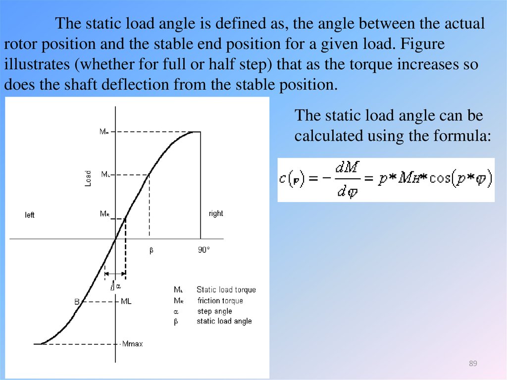
The static load angle is defined as, the angle between the actualrotor position and the stable end position for a given load. Figure
illustrates (whether for full or half step) that as the torque increases so
does the shaft deflection from the stable position.
The static load angle can be
calculated using the formula:
89
90. Step response
It was pointed out earlier that the single-step response is similarto that of a damped second-order system. We can easily estimate the
natural frequency n in rad/s from the equation
2n
slope of torgue-angle curve
totel inertia
90
91.
Knowing n , we can judge what the oscillatory part of theresponse will look like, by assuming the system is undamped. To refine
the estimate, and to obtain the settling time, however, we need to
estimate the damping ratio, which is much more difficult to determine as
it depends on the type of drive circuit and mode of operation as well as
on the mechanical friction. In VR motors the damping ratio can be as low
as 0.1, but in hybrid types it is typically 0.3–0.4. These values are too
low for many applications where rapid settling is called for.
91
92.
Two remedies are available, the simplest being to Wt amechanical damper of the type mentioned above. Alternatively, a special
sequence of timed command pulses can be used to brake the rotor so that
it reaches its new step position with zero velocity and does not
overshoot. This procedure is variously referred to as ‘electronic
damping’, ‘electronic braking’ or ‘back phasing’. It involves reenergising the previous phase for a precise period before the rotor has
reached the next step position, in order to exert just the right degree of
braking. It can only be used successfully when the load torque and inertia
are predictable and not subject to change. Because it is an open-loop
scheme it is extremely sensitive to apparently minor changes such as
day-to-day variation in friction, which can make it unworkable in many
instances.
92