


 Программирование
 Программное обеспечение
Похожие презентации:


")

Lab view run time installation
1.
Lab view run time installation1. Lab view run time installation
Lab view run time 2010 should be installed in order to implement R-manager.
Download the lab view run time program in the server and then install as an order below
http://biz.lgservice.com
① Input employee
number and pw
② Select TECHNICIAN CARE of SITE LINK on top
* R-manager program
- LVRTE2010min.exe
- visa462runtime.exe
- R-Manager.exe
③ Select Firmware Management of SITE LINK on left
④ Check the Registration Date and Product
(‘Vacuum Cleaner’) and Click the Search button)
⑤ Select the program from a list and save in attached file USB
(Use the formatted USB that is only for updating)
1
2.
Lab view run time installation1. Lab view run time 2010 installation
LVRTE2010min.exe
① Unzip
② Click next
③ Click next
④ Make an agreement with the license and then click next
⑤ Click next
⑥ Waiting
⑦ Click next
2
3.
Lab view run time installation1. Lab view run time 2010 installation
visa462runtime.exe
① Unzip
④ Click next
② Click next
③ Click next
⑤ Uncheck the box and then click next
⑥ Completion
3
4.
R-Manager RK diagnosis program use method2. R-Manager RK diagnosis program connection method
2.1. TCP connection method (1)
① Open the cover while power is off.
② Open USB cap, put wireless LAN card,
and then close the cover.
(Purchase and use the Unicorn MW-150U)
③ Turn the power on
④ Press ▼(Down) button for more than 3 seconds while pressing time setting button at the same
time by using a remote controller.
Confirm that the diagnosis program connection is ready by the sound of
“Ring ring~ ring ring ring ~ Starting inspection mode.”
4
5.
R-Manager RK diagnosis program use method2. R-Manager RK diagnosis program connection method
2.1. TCP connection method (2)
⑤ Set a wireless IP of the PC
that will be connected to a robot
⑥ Select internet protocol (TCP/IP)
⑧ Connect to RK_APMOD in a wireless network
connection status setting window
⑦ IP address : 192.168.0.110
Serve net mask : 255.255.255.0
⑨ Automatically connect to the set when confirming
the program connection (TCP Connection) as a
figure below after implementing
R-Manager program. In case of no
connection after pressing
Reconnection button, re-implementing
from ④
5
6.
R-Manager RK diagnosis program use method2. R-Manager RK diagnosis program use method
2.1. R-manager program (Main screen)
Charge & discharge regarding battery
Upper part camera
Sensor
information
Communication connection method
&
Communication port setting
R-Manager program information
Main body button,
dust bin,
mop sense
switch
RTC,
keyboard
control
Communica
tion
connection
Control regarding
motor
Model name, vision information
IP information
6
7.
R-Manager RK diagnosis program use method2. R-Manager RK diagnosis program use method
2.1. R-manager program (Main screen)
2.1.1. Communication connection method & communication port setting
Connection Type
- TCP connection : Wireless LAN card use.
- UART connection : Serial cable use.
VISA resource name
- Communication port setting button when UART connection is selected as a connection type
Communication connection
- Green light is on when connection is activated
2.1.2. Model name, vision information, TCP information
Model ID
- B0 : VR627xLVM Ser., VR626xLVM Ser.
Vision Ver.
- Vision board (Upper part camera) program version
Main Ver.
- Main board program version (Note* : Should be the same number with vision ver.)
IAP Ver.
- Main board boot loader version
TCP Information
- IP information of robot
7
8.
R-Manager RK diagnosis program use method2. R-Manager RK diagnosis program use method
2.1. R-manager program (Main screen)
2.1.3. Sensor information
* Side PSD sensor [mm] – Side PSD sensor
Function : Wall drive / Map Building
Sense distance : 20~ 150 mm
In case where there is no barrier : 150 mm
Sensor characteristic
Advantage : Possible to calculate the straight distance to the barrier and
position accurately
Disadvantage : Narrow sense range and greatly influenced by external light
interference (외란광)
Left PSD
Right
PSD
8
9.
R-Manager RK diagnosis program use method2. R-Manager RK diagnosis program use method
2.1. R-manager program (Main screen)
2.1.3. Sensor information
* Ultrasonic sensor [mm] – Ultrasonic sensor
Function: Barrier sense / Wall drive
Sense distance: 50 ~250 mm
In case where there is no barrier : 250 mm
Sensor characteristic
Advantage – Possible to sense a wide range with a small amount of sensors
Disadvantage –Difficult to sense thin and angulated barriers such as legs of a desk
and a chair
Tx
Rx
Rx
Tx: Transmitter
(Transmission part)
Rx: Receiver (Reception
part)
9
10.
R-Manager RK diagnosis program use method2. R-Manager RK diagnosis program use method
2.1. R-manager program (Main screen)
2.1.3. Sensor information
* Gyro Sensor [mm] – Angle sensor
Function: Angle measurement
Operation range: -180.0 ~ 180.0 (Degree)
Initial value : 0 (CW: Clock wise - / CCW: Counter clock wise +)
Sensor characteristic
Advantage – Correct the straight drive by measuring relative angles
Disadvantage – Not resistant to temperature changes and external shock
10
11.
R-Manager RK diagnosis program use method2. R-Manager RK diagnosis program use method
2.1. R-manager program (Main screen)
2.1.3. Sensor information
* Accelerometer Sensor - Acceleration sensor
Function: Acceleration (Shock) measurement
Operation range: -2048~+2048(-2G ~+2G)
Sensor characteristic
Advantage – Sense collision by measuring the amount of speed change
(Mechanic bumper replacement)
Disadvantage – Not resistant to temperature changes and external shock
+Y
+X
+Z
-X
-Z
X
-Y
11
12.
R-Manager RK diagnosis program use method2. R-Manager RK diagnosis program use method
2.1. R-manager program (Main screen)
2.1.3. Sensor information
* Cliff Sensor - Cliff/ doorsill sense sensor
Function: Cliff and doorsill sense
Sense distance: -18 ~ 150(mm)
In case where there is no barrier : 150(Doorsill: - / cliff: + floor : 35mm)
Sensor characteristic:
Advantage – Less influenced by colors of barriers
Disadvantage – Mis-operation if there are marble and clear color changes
Center
Right
Left
Possible range of sensor correction [mm] : -30 ~ +40 / 35
Sensor sensitivity adjustment time: When cleaning starts (Should start on the flat floor)
Items to be confirmed : After rotating an agitator, left/ right sensor change should be
confirmed by using graphs (-4 ~ +4)
12
13.
R-Manager RK diagnosis program use method2. R-Manager RK diagnosis program use method
2.1. R-manager program (Main screen)
2.1.3. Sensor information
* Cliff sensor - Doorsill/ cliff sensor
Function: Measure the relative migration distance of a main body
Principle of sensor: Measure the migration distance and direction by taking an image of the floor surface
image (3x3mm) every once in a while
SQUAL: The number of characteristic dot of an floor image that can be used in calculation of the amount
of migration
Sensor characteristic
Advantage – Possible to measure the actual migration distance of a main body /Correct errors caused by
slipping
Disadvantage – Decline performance on a floor without patterns/ mis-operation caused by dust
• SQUAL use range
In case of more than 40 Use a migration value to position correction
In case of more than 23 Use when judging a stuck sense of a main body
In case of less than 23 OFS sensor should not be used
13
14.
R-Manager RK diagnosis Program use method2. R-Manager RK diagnosis program use method
2.1. R-manager program (Main screen)
2.1.3. Sensor information
Docking signal range
LN (Left near)
Left near distance
RN (Right near)
Right near distance
LF (Left far)
Left far distance
RF (Right far)
Right far distance
CN (Center near)
Center near distance
CF (Center far)
Center far distance
Automatic charge induction signal/ Place sensors sense remote controller signal
Left Front
(Left front side)
Right Front
(Right front side)
LN
Left Rear
(Left rear side)
LF
CN
CF
RN
RF
Right Rear
(Right rear side)
14
15.
R-Manager RK diagnosis Program use method2. R-Manager RK diagnosis program use method
2.1. R-manager program (Main screen)
2.1.4. Charge & discharge regarding batteries
* Battery management system – Battery management
Voltage range: 12.7V ~16.8V
Residual quantity level of a battery
High : More than 70%
Middle: 40% ~ 70%
Low : 20% ~
Dock: 5% ~20%
LB (Low battery): Under 5%
Current range
When discharging: Average current 200~400mA
Motor derive 900 ~1100mA
When charging: 300 ~ 1100 mA
Charger terminal contact confirm (Contact)
When contacting a charger, docking signal
occurrence is blocked
Battery state confirm (Battery State)
CONSUMING: Waiting
CHARGER CONTACT: Charge terminal connection
CHARGING : Charging
CHARGING COMPLETE : Charge completion
SWITCH ERROR : Main power switch of a main body is off
15
16.
R-Manager RK diagnosis Program use method2. R-Manager RK diagnosis program use method
2.1. R-manager program (Main screen)
2.1.5. Control regarding motors
* Motor control – Motor control
Wheel motor (Left/ right wheel motor)
Straight drive speed / rotation speed: Straight drive/ rotation speed [mm/sec] of a main body by
wheel rotation
Speed :The current wheel speed [mm/sec] measured by wheel motor encoder
Current (Current): Wheel motor use current [10mA]
Drop (Wheel drop sense): Whether or not a wheel drop sense switch is operated
Agitator motor (Agitator motor)
Agitator motor speed (RPM) – Error occurrence in case where less than 1000RPM
Suction motor (Suction motor)
Suction motor current (10mA) –When a motor is stuck, current is increased drastically
All run / All stop (Whole motor control)
Whole motor (Agitator, suction, wheel)
is on/off with a currently set speed
Turbo
Agitator
motor
회전솔 모터fff
Agitator RPM : 1000 1200 RPM
Suction motor : 8500 10000 RPM
왼쪽 wheel
바퀴
Left
오른쪽
Right바퀴
wheel
흡입 모터
Suction
motor
16
17.
R-Manager RK diagnosis Program use method2. R-Manager RK diagnosis program use method
2.1. R-manager program (Main screen)
2.1.6. Upper part camera
* Ceiling vision sensor – Upper part camera
Camera image confirm
Get Robot Img : Image capture
Movie button : Take images periodically which is set
(Should be minimum 500ms)
CV-SLAM
Position detection and mapping A
are performed at the
same time from an image of ceiling
17
18.
R-Manager RK diagnosis Program use method2. R-Manager RK diagnosis program use method
2.1. R-manager program (Main screen)
2.1.7. Infrared light reception & micro SW
* On / off switch check – Switch type inspection
Cover touch button (Upper part touch button)
Off
On
Dust bin sense switch
Mop sense switch
18
19.
R-Manager RK diagnosis Program use method2. R-Manager RK diagnosis program use method
2.1. R-manager program (Main screen)
2.1.8. RTC, keyboard control
* PC keyboard control / RTC time –Computer keyboard control / main
body set time
a : Agitator motor on / off
s : Suction motor on / off
t : Turbo mode on / off
↑, ↓ : Reverse speed control before setting
Set speed is accelerated/ decelerated by 10 cm/sec when clicking
←,→ : Set left and right rotation speed control
Set speed is accelerated/ decelerated by 10 deg/sec when clicking
Space bar : All motor off
19
20.
R-Manager RK diagnosis Program use method2. R-Manager RK diagnosis program use method
2.1. R-manager program (Graph screen)
Temporarily stop the real-time graph
Multiple selection
is possible by
using a data list
Ctrl button
Communication connection method
&
Communication port setting
Plot list
Communication
connection
Model name, vision information
IP information
20
21.
R-Manager RK diagnosis Program use method2. R-Manager RK diagnosis program use method
2.1. R-manager program (Log screen)
Save path setting
Save start/ stop
Save period setting
Save data initialization
Saved data count
Data list selected
from a graph screen
Communication connection method
&
Communication port setting
Saved data (*.xls)
Communication
connection
Model name, vision information
IP information
21
22.
Black box viewer manual1. Black box viewer installation method
Download Black Box Install file from a server (http://smile.lge.com => SCS ) and then install as an order below
① Perform install program
④ Install progress status
② Click Next
⑤ Click install end OK button
③ Select the path which black box viewer
program is installed and then click Install
button
⑥ After completing the installation, confirm the
implemented file
22
23.
Black box viewer manual2. Black box viewer explanation
B.B file list
Manu bar
B.B file loading
Roboking accumulated data loading
Event tag list
*B.B file (One unit per cleaning) list
Occurred event list
(Start, error, trajectory ,, etc)
Map
Mark barriers and cleaning areas
Simulation control box
Time slide bar, barrier color setting
event color setting section
Event list
Time sequencing organization
of a list that is selected on
an event tag list
Information
Mark detail information of
selected event
* B.B : Black Box
23
24.
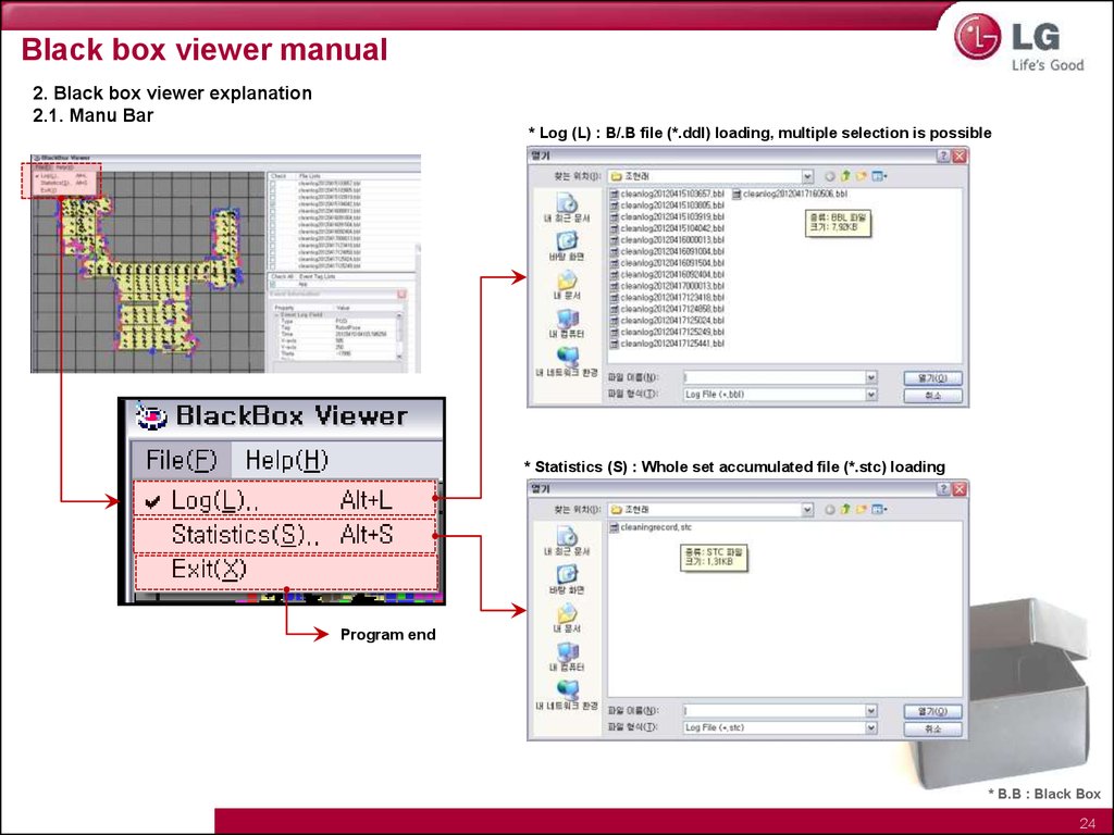
Black box viewer manual2. Black box viewer explanation
2.1. Manu Bar
* Log (L) : B/.B file (*.ddl) loading, multiple selection is possible
* Statistics (S) : Whole set accumulated file (*.stc) loading
Program end
* B.B : Black Box
24
25.
Black box viewer manual2. Black box viewer explanation
2.1. Manu bar
Statistics (S) : Whole set accumulated file (*.stc) data list (1)
Statistics viewer screen
Confirm accumulated data of
Roboking since outgoing
No.
Indication
Error classification
Indication method
1
RESET_COUNT
Accumulated number of reset occurrence
Times
2
KIDNAP_COUNT
Accumulated number of kidnap occurrence
Times
3
RECOVERY_OK
Accumulated number of kidnap success
Times
4
RECOVERY_FAIL
Accumulated number of kidnap failure
Times
5
START_SB
Accumulated number of meticulous cleaning mode start
Times
6
START_ZZ
Accumulated number of zigzag mode start
Times
7
START_SPOT
Accumulated number of intense cleaning mode start
Times
8
START_MACRO
Accumulated number of designated area mode start
Times
9
FINISH_SB
Accumulated number of meticulous cleaning completion
Times
10
FINISH_ZZ
Accumulated number of zigzag cleaning completion
Times
11
FINISH_SPOT
Accumulated number of intense cleaning completion
Times
12
FINISH_MACRO
Accumulated number of designated area cleaning completion
Times
13
ERR_DUSTBIN
Accumulated number of dust bin error occurrence
Times
14
ERR_ROBOTLIFT
Accumulated number of main body lifting error occurrence
Times
15
ERR_LWHEELSTUCK Accumulated number of stuck error occurrence on left wheel
Times
16
ERR_RWHEELSTUCK Accumulated number of stuck error occurrence on right wheel
Times
17
ERR_AGITATOR
18
ERR_SUCTION
Accumulated number of stuck error on main body floor agitator
Times
Accumulated number of stuck error on suction motor
Times
19
ERR_ROBOTSTUCK Accumulated number of stuck error on main body
Times
20
ERR_WHEELDROP
Accumulated number of wheel lifting error
Times
21
ERR_ENCODER_L
Accumulated number of left wheel encoder error
Times
22
ERR_ENCODER_R
Accumulated number of right wheel encoder error
Times
23
ERR_MOTOR_L
Accumulated number of left motor short error
Times
24
ERR_MOTOR_R
Accumulated number of right motor short error
Times
25
26.
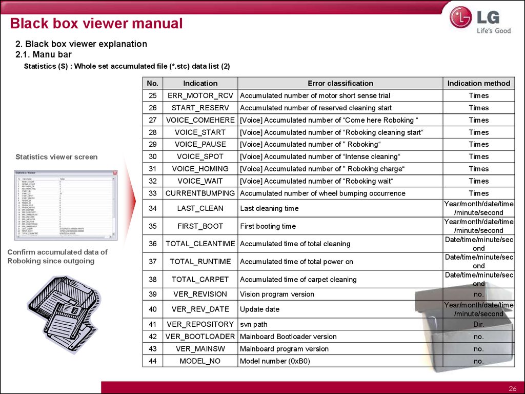
Black box viewer manual2. Black box viewer explanation
2.1. Manu bar
Statistics (S) : Whole set accumulated file (*.stc) data list (2)
No.
25
26
27
Statistics viewer screen
Error classification
ERR_MOTOR_RCV Accumulated number of motor short sense trial
START_RESERV
Accumulated number of reserved cleaning start
VOICE_COMEHERE [Voice] Accumulated number of “Come here Roboking “
Indication method
Times
Times
Times
28
VOICE_START
[Voice] Accumulated number of “Roboking cleaning start“
Times
29
VOICE_PAUSE
[Voice] Accumulated number of " Roboking“
Times
30
VOICE_SPOT
[Voice] Accumulated number of “Intense cleaning“
Times
31
VOICE_HOMING
[Voice] Accumulated number of " Roboking charge“
Times
32
VOICE_WAIT
[Voice] Accumulated number of “Roboking wait“
Times
33
CURRENTBUMPING Accumulated number of wheel bumping occurrence
34
LAST_CLEAN
Last cleaning time
35
FIRST_BOOT
First booting time
36
Confirm accumulated data of
Roboking since outgoing
Indication
TOTAL_CLEANTIME Accumulated time of total cleaning
37
TOTAL_RUNTIME
Accumulated time of total power on
38
TOTAL_CARPET
Accumulated time of carpet cleaning
39
VER_REVISION
Vision program version
40
VER_REV_DATE
Update date
41
VER_REPOSITORY svn path
42
VER_BOOTLOADER Mainboard Bootloader version
43
VER_MAINSW
44
MODEL_NO
Times
Year/month/date/time
/minute/second
Year/month/date/time
/minute/second
Date/time/minute/sec
ond
Date/time/minute/sec
ond
Date/time/minute/sec
ond
no.
Year/month/date/time
/minute/second
Dir.
no.
Mainboard program version
no.
Model number (0xB0)
no.
26
27.
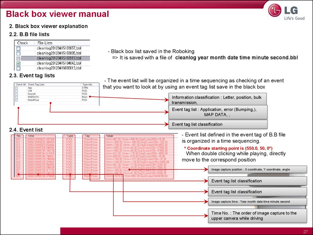
Black box viewer manual2. Black box viewer explanation
2.2. B.B file lists
- Black box list saved in the Roboking
=> It is saved with a file of cleanlog year month date time minute second.bbl
2.3. Event tag lists
- The event list will be organized in a time sequencing as checking of an event
that you want to look at by using an event tag list save in the black box
Information classification : Letter, position, bulk
transmission,
Event tag list : Application, error (Bumping,),
MAP DATA, ,
Event tag list classification
2.4. Event list
- Event list defined in the event tag of B.B file
is organized in a time sequencing.
* Coordinate starting point is (550.0, 50, 0°)
When double clicking while playing, directly
move to the correspond position
Image capture position : X coordinate, Y coordinate, angle
Event tag list classification
Event tag list classification
Image capture time : Year month date time minute second
Time No. : The order of image capture to the
upper camera while driving
27
28.
Black box viewer manual2. Black box viewer explanation
2.5. Information
Right click
When clicking information (Example)
Cleaning start meticulous cleaning
(SB)
When clicking display
Image capture position
- Indicate the correspond event on the map
Error notification, dust bin error
Message for map data save
- Possible to see the details of correspond event list
=> Event type, tag, occurrence time, coordinate, angle event
explanation
28
29.
Black box viewer manual2. Black box viewer explanation
2.6. Map
- Driving information saved in B.B can be confirmed visually
- Debugging can be done by confirming the event (Cliff, doorsill)
- Each color can be set and confirmed in the simulation control box
- Classified three areas (Cleaning area/ non-cleaning area/barrier)
2.7. Simulation control box
Possible to set regarding map
- Possible to play and stop based upon an event list content
- Possible to set color and shape of occurred event
29
30.
Black box viewer manual3. Black box viewer use method
3.1. Program download for black box data upload
Black box save implementation script should be downloaded from the server
http://smile.lge.com
① Input employee
number and pw
② Select SCS of SITE LINK
③ Click CS support community
⑤ Select the program from a list and save in attached file USB
(It is not implemented well on a security program installed (Navi) PC
because the file is save as a code.)
④ Click technology/
Specification notice
* File list
- blackbox.sh (File)
- blackbox (Folder)
Place above tow files at the top
path of the USB
B.B data is automatically saved
under the black box folder
30
31.
Black box viewer manual3. Black box viewer use method
3.1. Program download for black box data upload
⑥ Open the cover while power is off.
⑦ Open USB cap and put USB memory that
the program for black box upload is saved.
Then close the cover
⑧ Turn the power on
⑨ Booting starts by showing a booting animation,
Upload starts with a voice guidance of “Black box data loading begins.” ,
Upload completion is notified with a voice guidance of
“Black box data loading is completed.” Then booting starts automatically.
31
32.
Black box viewer manual3. Black box viewer use method
3.1. Program download for black box data upload
① Black box viewer program implementation
② Click File -> Log and load log file
③ Click the list which you want to look at
on the check box of the event tag list
④ Upload completion
Debugging by using the loaded file
=> Find out the error type and position
=> Improve robot key use environment for users
⑤ Implement start/end/color selection by using a simulation control box
32
33.
Smart diagnosis1. Smart diagnosis perform
• Function that the problematic information of main parts such as sensor
and motor of the main body is found out itself and guides customers
with a method to take action via voice
Operation condition : Press “Smart diagnosis” button on the remote controller while charging
* Smart diagnosis start condition
- While charging the charger
- In status of non-installation of mop (Prevention of
sensor misjudgment)
- In status of installation of dust bin
- Minimum battery status is more than medium
- In status of non-lifted wheels
* If a reservation is set, the reservation is canceled and then the diagnosis starts
2. Diagnosis result voice message repetition function and diagnosis mode removal
- Diagnosis result voice message can be repeated as much as the users want
※ In case where there is any problem in barrier sense
sensor, ultrasonic sensor, cliff sense sensor, only voice
message is provided without returning to the charger
and then the smart diagnosis function ends.
(Implement by pressing the charge key)
-Diagnosis mode removal is possible using a stop key only
Smart diagnosis start
Reverse
Rotation to right (90’)
Rotation to left (270’)
※ When there is no operation for a minute after a voice
message guidance, it automatically returns to the charge
mode
Forward (50cm)
Rotation to left (180’)
Automatic charge
perform
&
Diagnosis result report
notification
33
34.
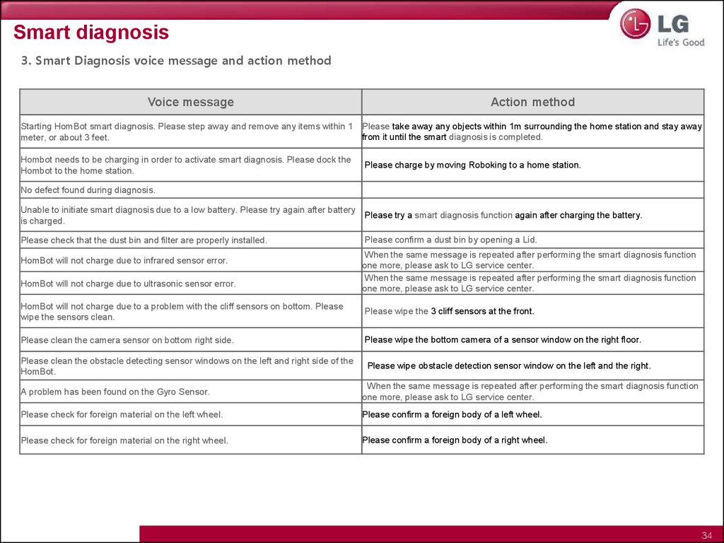
Smart diagnosis3. Smart Diagnosis voice message and action method
Voice message
Action method
Starting HomBot smart diagnosis. Please step away and remove any items within 1 Please take away any objects within 1m surrounding the home station and stay away
from it until the smart diagnosis is completed.
meter, or about 3 feet.
Hombot needs to be charging in order to activate smart diagnosis. Please dock the
Hombot to the home station.
Please charge by moving Roboking to a home station.
No defect found during diagnosis.
Unable to initiate smart diagnosis due to a low battery. Please try again after battery
Please try a smart diagnosis function again after charging the battery.
is charged.
Please check that the dust bin and filter are properly installed.
HomBot will not charge due to infrared sensor error.
HomBot will not charge due to ultrasonic sensor error.
Please confirm a dust bin by opening a Lid.
When the same message is repeated after performing the smart diagnosis function
one more, please ask to LG service center.
When the same message is repeated after performing the smart diagnosis function
one more, please ask to LG service center.
HomBot will not charge due to a problem with the cliff sensors on bottom. Please
wipe the sensors clean.
Please wipe the 3 cliff sensors at the front.
Please clean the camera sensor on bottom right side.
Please wipe the bottom camera of a sensor window on the right floor.
Please clean the obstacle detecting sensor windows on the left and right side of the
HomBot.
Please wipe obstacle detection sensor window on the left and the right.
A problem has been found on the Gyro Sensor.
When the same message is repeated after performing the smart diagnosis function
one more, please ask to LG service center.
Please check for foreign material on the left wheel.
Please confirm a foreign body of a left wheel.
Please check for foreign material on the right wheel.
Please confirm a foreign body of a right wheel.
34
35.
Smart diagnosis3. Smart Diagnosis 음성 알림 및 조치 방법(2)
Voice message
A problem has been found on the left wheel sensor.
Action method
Please confirm if there is a foreign body on an agitator.
A problem has been found on the right wheel sensor.
When the same message is repeated after performing the smart diagnosis function one more,
please ask to LG service center.
A problem has been found with the brush. Please check for any foreign material.
Remove the foreign object in the rotating brush
A problem has been found in the suction motor.
Diagnosis result can be listened again if pressing a charging button of a main body and a
remote controller. If pressing a stop button, smart diagnosis is completed.
A problem has been found in the acceleration sensor.
Please try one time smart diagnosis again after turning off and on the main power switch of the
back of Roboking.
Please ask to LG service center in case of repeating the message.
In order to listen to the smart diagnosis result again, please press the charging button. To stop,
please press the stop button.
Please try smart diagnosis again after turning the main power switch on the back of the
HomBot 'Off' then 'On' again. If the problem continues, please contact LG Electronics customer Turn on the power switch
care.
Smart diagnosis mode will be turned off.
Smart Diagnosis mode will not operate with the mop plate attached. Please try again after
removing it.
Please try smart diagnosis function after removal of the mop plate.
Smart diagnosis has failed to complete its diagnostics. Please try again after turning the main
power switch on the back of the HomBot 'Off' then 'On' again.
Please try one time smart diagnosis again after turning off and on the main power switch of the
back of Roboking. Please do not touch Roboking or interrupt driving until the smart diagnosis is
completed.
Please check if the charging terminal is damaged or dirty.
Please wipe the bottom surface of Roboking and a change terminal of a home station.
35
36.
Program upgrade1. Update program download method (1)
Download the file to upgrade in the server and then and then upgrade as an order below
http://smile.lge.com
① Input employee
number and pw
② Select SCS of SITE LINK
③ Click CS support community
⑤ Select the program from a list and save in attached file USB
(Use the formatted USB that is only for updating)
* File List
- RKHIT_verXXXX.zip
(XXXX is a program version)
④ Click technology/
Specification notice
36
37.
Program upgrade1. Update program download method (2)
⑥ USB open
⑦ Implement unzip here
⑧ Confirm whether the usr folder and update.sh file are positioned on the top
of the USB
37
38.
Program upgrade1. Update program download method (3)
⑨ Open the cover while power is off.
⑩ Open USB cap and put USB memory that
update program is saved. Then close the cover.
⑪ Turn the power on
⑫ Booting starts by showing a booting animation,
Update starts a voice guidance of “Software will be updated.”,
Update completion is notified with a voice guidance of
“Software update is completed.” and the power turns off.
Then booting starts with the updated program.
38
39.
Program upgrade method (3)2. Program version confirm method
Program version is informed by voice when pressing the order listed below using a remote controller
(ex) In case where version is 1234 “One two three four”)
Turbo
Turbo
Mode
Mode
Mode
Turbo
Turbo
Stop
Stop
Stop
39