


")


 operator in Pointers")


")
")

")
")
")

")
")
")
")

")
")
")
")


")
")
")


")
")
")


")


")
")


")
")
")
")
")
")


")


")
 Программное обеспечение
Похожие презентации:


")
")

Computer Architecture
1.
CS250Computer Architecture
Gustavo Rodriguez-Rivera
Computer Science Department
Purdue University
2. General Information
Web Page:http://www.cs.purdue.edu/homes/cs250
Office: LWSN1185
E-mail: [email protected]
Textbook:
Essentials of Computer Architecture
D. E. Comer
Prentice Hall
0-13-149179-2
3. Mailing List
They wil be created automatically. You don’t need touse mailer.
4. PSOs
There is no PSO the first week.The projects will be explained in the PSOs.
E-mail questions to
[email protected]
TAs office hours will be posted in the web
page.
5. Grading
Grade allocationMidterm:
Final:
Projects:
25%
25%
50%
Exams also include questions about the
projects.
6. Course Organization
1. Basics Fundamentals ofDigital Logic
Data Representation
2. Processors
Types of Processors
Instruction Sets
Assembly Language
7. Course Organization
3. MemoryTypes of Memory
Physical and Virtual Memory
Caching
4.Input/Output
Devices and Interfaces
Buses
Device Drivers
8. Course organization
5. Advanced TopicsParallelism
Performance Measurement
Architectural Hierarchy
9. Approach
We will cover Computer ArchitectureFrom the programmers point of view.
How it influences the programmers choices.
We will not cover
Low engineering details
VLSI design
10.
II. Fundamentals of Digital Logic11. Voltage and Current
VoltageMeasure of potential Force
It is measured in Volts
Current
Measure of electron flow across a wire
It is measured in Ampers (Amps)
12. Voltage
Voltage is measured with a voltmeter acrosstwo points.
Typical digital circuits work with 5 volts:
Ground - 0 volts – represent a “0”
Power – 5 volts – represent a “1”
13. Transistor
Building block of digital circuitsActs like a switch
A transistor has three connections:
Emitter
Base
Collector
Small Current
Collector
Base
Emitter
Large
Current
The current between “Base” and “Emitter”
controls the current between “Collector” and
“Emitter”.
14. Boolean Logic
It gives the formal basis for digital circuitsIt uses three basic functions
AND
A
B
A
B
0
0
0
OR
A and B
A
B
A or B
0
0
0
0
A
not A
1
0
0
1
1
0
1
1
0
0
1
0
1
1
0
1
1
1
1
1
1
A and B
A
B
A or B
NOT
15. Boolean Logic
You will find that Nand and Nor Gates arevery popular.
By using them, there is no need of Not gate
NOR
NAND
A
B
A
B
1
0
0
1
1
1
0
1
0
1
0
1
1
0
0
1
1
0
1
1
0
A
B
0
0
0
A nand B
A
B
A nor B
16. Boolean Logic
In digital circuits 0 and 1 are represented as0 = 0 volts
1 = +5 volts
You can interconnect digital circuits with each
other to create complex Boolean
expressions.
(A and B) is represented as AB
(A or B) is represented as A+B
(not A) is represented as A’
17. Boolean Logic
Example:A
AB’
B’
A’B +AB’
A
Truth Table
B
B
A’ B
A’
A
B
A xor B
0
0
0
0
1
1
1
0
1
1
1
0
18. Truth Tables to Boolean Expressions
From a Truth table you can create a booleanexpression
You can represent the boolean function as a
Sum of products: Example z=x’y+xy’
Product of sums: Example z=(x+y)(x’y’)
19. Sum of Products
To create a sum of products from a truth table,take the 1s in z (the output) and use the variables
for that row to create the product. If the variable is
x=1 then use x, otherwise if x=0 use x’.
Truth Table
x
y
z
0
0
0
0
1
1
1
0
1
1
1
0
z= x’y + xy’
20. Product of Sums
To create a product of sums from a truth table,take the 0s in z (the output) and use the variables
for that row to create the product. If the variable is
x=0 then use x, otherwise if x=1 use x’.
Truth Table
x
y
z
0
0
0
0
1
1
1
0
1
1
1
0
z= (x+y)(x’+y’)
21. Example: Implementing add
Assume we want to add two numbers where eachnumber will be one bit long.
The resulting number may be two bits long
A plus B
This can be represented as:
R0 = A’B+B’A
R1 = AB
A
B
R1 R0 In decimal
0
0
0 0
0
0
1
0 1
1
1
0
0 1
1
1
1
1 0
2
22. Implementing Add
To implement an adder for 8 bits or 32 bits,many more gates are required.
23. Boolean Algebra
You can manipulate the boolean expressionslike normal algebraic expressions.
Properties
Commutative:
Associative:
AB = BA
A+B=B+A
(A+B)+C = A+(B+C)
Distributive
A(B+C) = AB+AC
24. De Morgan’s Law
Negation of expressions(A+B)’ = A’B’
(AB)’ = A’ + B’
25. Boolean Expression Reduction
You can simplify Boolean expressions to use fewergates:
Example:
z = a’b’c + a’b’+ ac’+ abc’
= a’b’(c+1) + ac’(1+b)
= a’b’+ac’
Example:
m = x’yz + x’yz’ + x’y’ + xyz
= x’y(z+z’) + x’y’ + xyz
= x’y+ x’y’ + xyz
= x’(y+y’) + xyz
= x’ + xyz
26. Karnaugh Maps
To make the simplification of booleanexpressions easier, we can use Karnaugh
maps.
A Karnaugh map is a way of expressing truth
tables
Adjacent columns or rows change only by
one digit.
They show when refactoring can be done.
27. Karnaugh Table example 1
Karnaugh Map for rGiven an expression
xy/z 00
01
11
10
0
0
1
1
0
1
1
1
0
0
xy/z 00
01
11
10
0
0
1
1
0
1
1
1
0
0
r = x’yz’+xyz’+x’y’z+x’yz
Build a 3 variable Karnaugh
map
Find the groups of 2, 4 or 8
1’s that are adjacent.
Make sure all 1s are
covered by the groups.
Build expression from
groups.
r = yz’ + x’z
r = yz’ + x’z
28. Karnaugh Table example 2
Karnaugh Map for rGiven an expression
r = x’yz’k’+x’yz’k+xyz’k’+xyz’k+
xyzk+xyzk’+x’y’zk’+xy’zk’
Build a 4 variable Karnaugh
map
Find the largest groups of 2,
4, 8 or 16 1’s that are
adjacent.
Make sure all 1s are covered
by the groups.
Build expression from groups.
r = yz’ + xy + y’zk’
xy/
zk
00
01
11
10
00
0
1
1
0
01
0
1
1
0
11
0
0
1
0
10
1
0
1
1
r = yz’ + xy + y’zk’
29. Using only NAND Gates
Very often you build the circuits using only NAND gates.To convert a sum of products to only NAND gates negate the
function twice and reduce
Example:
z = x XOR y = xy'+x'y
Now if you negate twice the right side and applying De Morgans
law.
z = ((xy'+x'y)')' = ((xy')'(x'y)')' = (x NAND y') NAND (x' NAND y)
Also, since x'= (x x)' = x NAND x and y' = y NAND y then we have:
z = (x NAND (y NAND y)) NAND ((x NAND x) NAND y)
30. XOR Using only NAND gates
x XOR y = (x NAND (y NAND y)) NAND ((x NAND x) NAND y)x’
10K
10K
10K
x
x XOR y
y
z
+5V
y
+5V
LED
x
y’
+5V
LED
LED
LED
31. Examples of Gates on 7400-Series Chips
Examples of Gates on 7400Series Chips32. Flip Flops
Basic unit of memoryTruth Table
R(reset)
S(set)
Q
Q’
S
R
Q
Q’
0
0
Keep previous value
0
1
0
1
1
0
1
0
1
1
Not allowed
33. Flip Flops. Keep Current value
00
R(reset)
Q
1
0
S(set)
0
0
1
Q’
1
R(reset)
Q
0
1
S(set)
0
0
Q’
34. Flip Flops. Reset and Set
10
R(reset)
Q
1
Reset
S(set)
0
0
0
1
Q’
1
R(reset)
Q
0
Set
1
S(set)
1
0
Q’
The Input R=1
and S=1 is not
allowed.
35. Binary Counter
Counts pulses (transitions from 0 to 1)Output is a binary number
Contains a terminal to reset ouput to 0
36. Binary Counter (4 bits)
Truth Table5
t
0
In
In
A
B
C
0
0
0
0
A
1
0
0
1
B
0
0
0
1
C
1
0
1
0
0
0
1
0
1
0
1
1
0
0
1
1
.
. . .
37. Clock
It is an electronic circuit that produces asequences of 0 1 0 1 0 1
The frequency is measured in hertz (Hz).
It is used to synchronize operations across
gates in active circuits.
5
0
38. Demultiplexor
It is a circuit used to select one outputA=1
B=1
C=0
0
0
0
1
0
0
0
0
ABC
0 0 0
0 0 1
0 1 0
0
1
1
1
1
1
0
0
1
1
1
0
1
0
1
39. Example of Circuit to Execute a Sequence of Steps
ClockCounter
Demultiplexer
Position drill
Start drill
Drill hole
Remove drill
Position screw
Drive screw
Remove screw driver
Move piece
40. Unused Gates
Since a chip may contain multiple gates, it ispossible to use some of the spare gates to do
other operations instead of adding a new
chip.
Example:
1 nand x = not x
41. Classification of Technologies
Small Scale Integration (SSI)Medium Scale Integration (MSI)
Intermediate logic such as demultiplexers and
counters
Large Scale Integration (LSI)
Basic Boolean Gates
Small embedded processors
Very Large Integration (VLSI)
Complex processors
42.
III. Data and Program Representation43. Memory of a Program
A program sees memory as an array of bytesthat goes from address 0 to 232-1 (0 to 4GB1)
That is assuming a 32-bit architecture.
(4GB-1) 232-1
0
44. Memory Sections
The memory is organized into sections called“memory mappings”.
232-1
Stack
Shared Libs
Heap
Bss
0
Data
Text
45. Memory Sections
Each section has different permissions:read/write/execute or a combination of them.
Text- Instructions that the program runs
Data – Initialized global variables.
Bss – Uninitialized global variables. They are
initialized to zeroes.
Heap – Memory returned when calling malloc/new. It
grows upwards.
Stack – It stores local variables and return
addresses. It grows downwards.
46. Memory Sections
Dynamic libraries – They are libraries shared withother processes.
Each dynamic library has its own text, data, and bss.
Each program has its own view of the memory that
is independent of each other.
This view is called the “Address Space” of the
program.
If a process modifies a byte in its own address
space, it will not modify the address space of
another process.
47. Example
Program hello.cint a = 5;
// Stored in
int b[20];
// Stored in
int main() { // Stored in
int x;
// Stored in
int *p =(int*)
malloc(sizeof(int));
}
data section
bss
text
stack
//In heap
48. Memory Gaps
Between each memory section there may be gapsthat do not have any memory mapping.
If the program tries to access a memory gap, the OS
will send a SEGV signal that by default kills the
program and dumps a core file.
The core file contains the value of the variables
global and local at the time of the SEGV.
The core file can be used for “post mortem”
debugging.
gdb program-name core
gdb> where
49. What is a program?
A program is a file in a special format that containsall the necessary information to load an application
into memory and make it run.
A program file includes:
machine instructions
initialized data
List of library dependencies
List of memory sections that the program will use
List of undefined values in the executable that will be
known until the program is loaded into memory.
50. Executable File Formats
There are different executable file formatsELF – Executable Link File
It is used in most UNIX systems (Solaris, Linux)
COFF – Common Object File Format
It is used in Windows systems
a.out – Used in BSD (Berkeley Standard Distribution) and
early UNIX
It was very restrictive. It is not used anymore.
Note: BSD UNIX and AT&T UNIX are the
predecessors of the modern UNIX flavors like
Solaris and Linux.
51. Building a Program
The programmer writes a program hello.cThe preprocessor expands #define, #include,
#ifdef etc preprocessor statements and generates a
hello.i file.
The compiler compiles hello.i, optimizes it and
generates an assembly instruction listing hello.s
The assembler (as) assembles hello.s and
generates an object file hello.o
The compiler (cc or gcc) by default hides all these
intermediate steps. You can use compiler options to
run each step independently.
52. Building a program
The linker puts together all object files as well asthe object files in static libraries.
The linker also takes the definitions in shared
libraries and verifies that the symbols (functions
and variables) needed by the program are
completely satisfied.
If there is symbol that is not defined in either the
executable or shared libraries, the linker will give
an error.
Static libraries (.a files) are added to the
executable. shared libraries (.so files) are not
added to the executable file.
53. Building a Program
hello.chello.i
C
Preprocessor
Editor
Programmer
hello.s
hello.o
Assembler
(as)
Compiler
(cc)
(static)
Optimizer
Executable
File (hello)
Shared Libraries
Linker (ld)
(.so files). Only
definitions. It does
Other .o files
Static libraries (.a files) not add to size of
They add to the size of executable.
the executable.
54. Original file hello.c
#include <stdio.h>main()
{
printf("Hello\n");
}
55. After preprocessor
gcc -E hello.c > hello.i(-E stops compiler after running preprocessor)
hello.i:
/* Expanded /usr/include/stdio.h */
typedef void *__va_list;
typedef struct __FILE __FILE;
typedef int
ssize_t;
struct FILE {…};
extern int fprintf(FILE *, const char *, ...);
extern int fscanf(FILE *, const char *, ...);
extern int printf(const char *, ...);
/* and more */
main()
{
printf("Hello\n");
}
56. After assembler
gcc -S hello.cassembling)
hello.s:
(-S stops compiler after
.align 8
.LLC0: .asciz "Hello\n"
.section
".text"
.align 4
.global main
.type
main,#function
.proc
04
main:
save
%sp, -112, %sp
sethi
%hi(.LLC0), %o1
or
%o1, %lo(.LLC0), %o0
call
printf, 0
nop
.LL2:
ret
restore
.
57. After compiling
“gcc -c hello.c” generates hello.ohello.o has undefined symbols, like the printf function
call that we don’t know where it is placed.
The main function already has a value relative to the
object file hello.o
csh> nm -xv hello.o
hello.o:
[Index]
Value
Size
Type
[1]
|0x00000000|0x00000000|FILE
[2]
|0x00000000|0x00000000|NOTY
[3]
|0x00000000|0x00000000|SECT
[4]
|0x00000000|0x00000000|SECT
[5]
|0x00000000|0x00000000|NOTY
[6]
|0x00000000|0x0000001c|FUNC
Bind
|LOCL
|LOCL
|LOCL
|LOCL
|GLOB
|GLOB
Other Shndx
|0
|ABS
|0
|2
|0
|2
|0
|3
|0
|UNDEF
|0
|2
Name
|hello.c
|gcc2_compiled
|
|
|printf
|main
58. After linking
“gcc –o hello hello.c” generates the helloexecutable
Printf does not have a value yet until the program is
loaded
csh> nm hello
[Index]
[29]
[65]
[43]
[60]
[71]
[72]
[67]
Value
Size
Type
|0x00010000|0x00000000|OBJT
|0x0001042c|0x00000074|FUNC
|0x00010564|0x00000000|FUNC
|0x000105c4|0x0000001c|FUNC
|0x000206d8|0x00000000|FUNC
|0x000206f0|0x00000000|FUNC
|0x00020714|0x00000000|FUNC
Bind
|LOCL
|GLOB
|LOCL
|GLOB
|GLOB
|GLOB
|GLOB
Other Shndx
|0
|1
|0
|9
|0
|9
|0
|9
|0
|UNDEF
|0
|UNDEF
|0
|UNDEF
Name
|_START_
|_start
|fini_dummy
|main
|atexit
|_exit
|printf
59. Loading a Program
The loader is a program that is used to run anexecutable file in a process.
Before the program starts running, the loader
allocates space for all the sections of the
executable file (text, data, bss etc)
It loads into memory the executable and
shared libraries (if not loaded yet)
60. Loading a Program
It also writes (resolves) any values in the executableto point to the functions/variables in the shared
libraries.(E.g. calls to printf in hello.c)
Once memory image is ready, the loader jumps to
the _start entry point that calls init() of all libraries
and initializes static constructors. Then it calls
main() and the program begins.
_start also calls exit() when main() returns.
The loader is also called “runtime linker”.
61. Loading a Program
ExecutableFile
Loader
(runtime linker)
(/usr/lib/ld.so.1)
Shared libraries (.so, .dll)
Executable
in memory
62. Static and Shared Libraries
Shared libraries are shared across differentprocesses.
There is only one instance of each shared
library for the entire system.
Static libraries are not shared.
There is an instance of an static library for
each process.
63. Memory and Pointers
A pointer is a variable that contains anaddress in memory.
In a 32 bit architectures, the size of a pointer
is 4 bytes independent on the type of the
pointer.
32
(4GB-1) 2 -1
Char c = ‘a’; //ascii 65
char * p = &c;
p:20:
12
c:12:
65
0
Address space
64. Ways to get a pointer value
1. Assign a numerical value into a pointerChar * p = (char *) 0x1800;
*p = 5; // Store a 5 in location 0x1800;
Note: Assigning a numerical value to a pointer isn't
recommended and only left to programmers of
OS, kernels, or device drivers
65. Ways to get a pointer value
2. Get memory address from another variable:int *p;
220:
buff[29]:216:
int buff[ 30];
p = &buff[1]; buff[1]:104:
buff[0]:100:
*p =78;
P: 96:
78
104
66. Ways to get a pointer value
3. Allocate memory from the heapint
p =
int
q =
*p
new int;
*q;
(int*)malloc(sizeof(int))
67. Ways to get a pointer value
You can pass a pointer as a parameter to afunction if the function will modify the
content of the parameters
void swap (int *a, int *b){
int temp;
temp=*a;
*a=*b;
*b=temp;
}
In main: swap(&x, &y)
68. Common Problems with Pointers
When using pointers make sure the pointer ispointing to valid memory before assigning or getting
any value from the location
String functions do not allocate memory for you:
char *s;
strcpy(s, "hello"); --> SEGV(uninitialized pointer)
The only string function that allocates memory is
strdup (it calls malloc of the length of the string and
copies it)
69. Printing Pointers
It is useful to print pointers for debuggingchar*i;
char buff[10];
printf("ptr=%d\n", &buff[5])
Or In hexadecimal
printf("ptr=0x%x\n", &buff[5])
Instead of using printf, I recommend to use
fprintf(stderr, …) since stderr is unbuffered
and it is guaranteed to be printed on the screen.
70. sizeof() operator in Pointers
The size of a pointer is always 4 bytes in a 32bit architecture independent of the type of the
pointer:
sizeof(int)==4 bytes
sizeof(char)==1 byte
sizeof(int*)==4 bytes
sizeof(char*)==4 bytes
71.
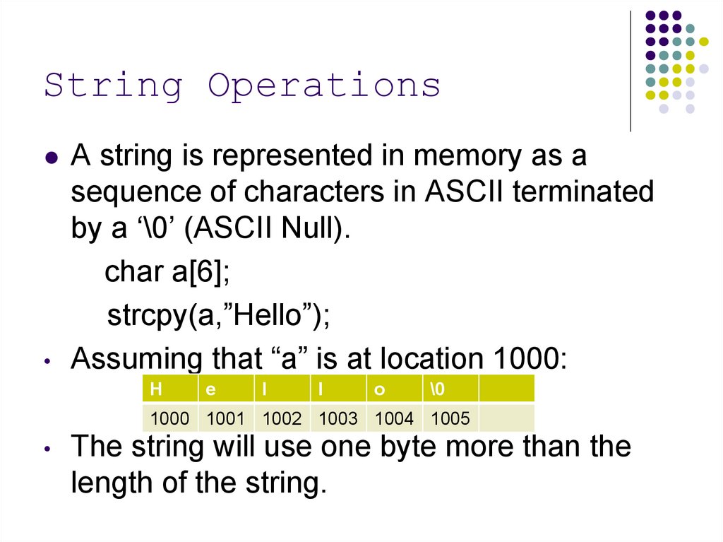
String OperationsA string is represented in memory as a
sequence of characters in ASCII terminated
by a ‘\0’ (ASCII Null).
char a[6];
strcpy(a,”Hello”);
Assuming that “a” is at location 1000:
H
e
l
l
o
\0
1000 1001 1002 1003 1004 1005
The string will use one byte more than the
length of the string.
72.
String OperationsThe C library (libc) provides simple string
functions to manipulate strings such as:
char * strcpy(char *dest, char *src)
char * strcat(char *dest, char *src)
Copies string from “src” to “dest” including char at the end. It
assumes that there is enough memory already in “dest”. It
does not allocate memory. It returns “dest”.
Appends string “src” at the end ofdest. It assumes that there
is enough memory already in “dest”. It returns “dest”.
char * strstr(char * hay, char * needle)
Returns a pointer of the first occurrence of the string
“needle” in the string “hay”.
73.
String OperationsIn general the string functions will not allocate
memory.
You have to allocate enough memory before
using them.
The only string function that allocates
memory is strdup(char * s) that allocates
memory using “malloc” and returns a copy of
the string passed in “s”.
74. Using Pointers to Optimize Execution
Assume the following function that adds the sum ofintegers in an array using array indexing.
int sum(int * array, int n)
{
int s=0;
for(int i=0; i<n; i++)
{
s+=array[i]; // Equivalent to
//*(int*)((char*)array+i*sizeof(int))
}
return s;
}
75. Using Pointers to Optimize Execution
Now the equivalent code using pointersint sum(int* array, int n)
{
int s=0;
int *p=&array[0];
int *pend=&array[n];
while (p < pend)
{
s+=*p;
p++;
}
return s;
}
76. Using Pointers to Optimize Execution
When you increment a pointer to integer it will beincremented by 4 units because sizeof(int)==4.
Using pointers is more efficient because no indexing
is required and indexing require multiplication.
Note: An optimizer may substitute the multiplication
by a “<<“ operator if the size is a power of two.
However, the array entries may not be a power of 2
and integer multiplication may be needed.
77. Array Operator Equivalence
We have the following equivalences:int a[20];
a[i]
- is equivalent to
*(a+i)
- is equivalent to
*(&a[0]+i) – is equivalent to
*((int*)((char*)&a[0]+i*sizeof(int)))
You may substitute array indexing a[i] by
*((int*)((char*)&a[0]+i*sizeof(int))) and
it will work!
C was designed to be machine independent
assembler
78. 2D Array. 1st Implementation
1st approachNormal 2D array.
int a[4][3];
a[i][j] ==
*(int*)((char*)a +
i*3*sizeof(int) +
j*sizeof(int))
a[3][2]:144:
a[3][1]:140:
a[3][0]:136:
a[2][2]:132:
a[2][1]:128:
a[2][0]:124:
a[1][2]:120:
a[1][1]:116:
a[1][0]:112:
a[0][2]:108:
a[0][1]:104:
a: a[0][0]:100:
79. 2D Array 2nd Implementation
2nd approachArray of pointers to rows
int*(a[4]);
for(int i=0; i<4; i++){
a[i]=(int*)malloc(sizeof(int)*3);
assert(a[i]!=NULL);
}
80. 2D Array 2nd Implementation
2nd approachArray of pointers to rows (cont)
a:
a[3]:112:
a[2]:108:
a[1]:104:
a[0]:100:
a[3][0] a[3][1]a[3][2]
a[2][0] a[2][1]a[2][2]
a[1][0]a[1][1]a[1][2]
a[0][0] a[0][1]a[0][2]
int*(a[4]);
a[3][2]=5
81. 2D Array 3rd Implementation
3rd approach. a is a pointer to an array of pointers torows.
int **a;
a=(int**)malloc(4*sizeof(int*));
assert( a!= NULL)
for(int i=0; i<4; i++)
{
a[i]=(int*)malloc(3*sizeof(int));
assert(a[i] != NULL)
}
82. 2D Array 3rd Implementation
a is a pointer to an array of pointers to rows.(cont.)
a:
a[3]:112:
a[2]:108:
a[1]:104:
a[0]:100:
int **a;
a[3][2]=5
a[3][0] a[3][1]a[3][2]
a[2][0] a[2][1]a[2][2]
a[1][0]a[1][1]a[1][2]
a[0][0] a[0][1]a[0][2]
83. Advantages of Pointer Based Arrays
You don’t need to know in advance the sizeof the array (dynamic memory allocation)
You can define an array with different row
sizes
84. Advantages of Pointer Based Arrays
Example: Triangular matrixa:
a[3]:112:
a[2]:108:
a[1]:104:
a[0]:100:
int **a;
a[3][0]
a[2][0] a[2][1]
a[1][0]a[1][1]a[1][2]
a[0][0] a[0][1]a[0][2]a[0][3]
85. Pointers to Functions
Pointers to functions are often used to implementPolymorphism in “C”.
Polymorphism: Being able to use the same
function with arguments of different types.
Example of function pointer:
typedef void (*FuncPtr)(int a);
FuncPtr is a type of a pointer to a function that
takes an “int” as an argument and returns “void”.
86. An Array Mapper
typedef void (*FuncPtr)(int a);void intArrayMapper( int *array, int n, FuncPtr func ) {
for( int = 0; i < n; i++ ) {
(*func)( array[ i ] );
}
}
int s = 0;
void sumInt( int val ){
s += val;
}
void printInt( int val ) {
printf("val = %d \n", val);
}
87. Using the Array Mapper
int a[ ] = {3,4,7,8};main( ){
// Print the values in the array
intArrayMapper(a, sizeof(a)/sizeof(int), printInt);
// Print the sum of the elements in the array
s = 0;
intArrayMapper(a, sizeof(a)/sizeof(int), sumInt);
printf(“total=%d\”, s);
}
88. A More Generic Mapper
typedef void (*GenFuncPtr)(void * a);void genericArrayMapper( void *array,
int n, int entrySize, GenFuncPtr fun )
{
for( int i = 0; i < n; i++; ){
void *entry = (void*)(
(char*)array + i*entrySize );
(*fun)(entry);
}
}
89. Using the Generic Mapper
void sumIntGen( void *pVal ){//pVal is pointing to an int
//Get the int val
int *pInt = (int*)pVal;
s += *pInt;
}
void printIntGen( void *pVal ){
int *pInt = (int*)pVal;
printf("Val = %d \n", *pInt);
}
90. Using the Generic Mapper
int a[ ] = {3,4,7,8};main( ) {
// Print integer values
s = 0;
genericArrayMapper( a, sizeof(a)/sizeof(int),
sizeof(int), printIntGen);
// Compute sum the integer values
genericArrayMapper( a, sizeof(a)/sizeof(int),
sizeof(int), sumIntGen);
printf(“s=%d\n”, s);
}
91. Swapping two Memory Ranges
In the lab1 you will implement a sort function that will sort any kindof array.
Use the array mapper as model.
When swapping two entries of the array, you will have pointers to
the elements (void *a, *b) and the size of the entry
entrySize.
void * tmp = (void *) malloc(entrySize);
assert(tmp != NULL);
memcpy(tmp, a, entrySize);
memcpy(a,b , entrySize);
memcpy(b,tmp , entrySize);
Note: You may allocate memory only once for tmp in the sort method and use it for
all the sorting to save muliple calls to malloc. Free tmp at the end.
92. String Comparison in Sort Function
In lab1, in your sort function, when sorting strings,you will be sorting an array of pointers, that is, of
"char* entries.
The comparison function will be receiving a “pointer
to char*” or a” char**” as argument.
int StrComFun( void *pa, void *pb) {
char** stra = (char**)pa;
char ** strb = (char**)pb;
return strcmp( *stra, *strb);
}
93. Bits and Bytes
BitByte
It stores 1 or 0
It is a group of 8 bits that can by individually
addressable.
Word
It is a group of 4 bytes (32 bit architecture) or
It is a group of 8 bytes (64 bit architectures)
The address of a word is aligned to either 4 or 8
bytes respectively (multiple of 4 or 8 bytes).
94. Interpretation of bits
Sometimes device registers are mapped tomemory. This is called Memory Mapped I/O.
In this case, a bit can represent some value
or state of the device:
Bit 0 – Printer is on-line/off-line
Bit 1 – Landscape/Letter mode
Bit 2 – Printer need attention
95. Interpretation of bits
Combination of bits are used as integers0
1
27
26
26
0
25
+
1
1
0
24
23
22
24 + 23 + 20 =
64 + 16 + 8 + 1 = 89
0
21
1
20
96. Hexadecimal Notation
Compact form to represent binary numbersIt uses base 16.
4 bits represent an hexadecimal digit
Hex
Binary
0
0
0
0
1
0
0
2
0
3
Hex
Binary
0
8
1
0
0
0
0
1
9
1
0
0
1
0
1
0
A
1
0
1
0
0
0
1
1
B
1
0
1
1
4
0
1
0
0
C
1
1
0
0
5
0
1
0
1
D
1
1
0
1
6
7
0
0
1
1
1
1
0
1
E
F
1
1
1
1
1
1
0
1
97. Hexadecimal Notation
Example:Hexadecimal: 0xF4534004
Binary:
1111 0100 0101 0011 0100 0000 0000 0100
Hexadecimal
F
4
5
3
4
0
0
4
Decimal:
15*167 + 4*166 + 5*165 + 3*164 + 4*163 + 4*160
98. Example of Character Encodings
EBCDICASCII
Unicode
99. EBCDIC
Extended Binary Coded Decimal InterchangeFormat
It was created by IBM in the 1960s
No longer in use except in some IBM
mainframes
100. ASCII
American Standard Code for InformationExchange
Used widely in UNIX and PCs
It uses 7 bits or 128 values
It only encodes the English Alphabet
101. ASCII Table
http://www.ascii.ws/ascii-chart.html102. UNICODE
Each character is 16 bits long (2 bytes)It is used to represent characters from most
languages in the world.
It is used for internationalization of programs.
Java and C# use UNICODE to represent
strings internally.
103.
Representation of StringsIn a “C” program a string is a sequence of characters delimited
by a null character.
0x48 0x65 0x6c 0x6c 0x6f 0x00
H
e
l
l
o
\0
In PASCAL the first byte represents the length of the string.
0x5
0x48 0x65 0x6c 0x6c 0x6f
Standard strings were limited to a length of 255
104.
Integer Representation inBinary
Each binary integer is represented in k bits
where k is 8, 16, 32, or 64 depending on the
type and architecture.
105.
Integer RepresentationExample
10010101 = 1*2^7 + 1*2^4+1*2^2+1*2^0 =
= 128 + 16 + 4 + 1
= 149
106. Binary Integer Addition
Same as decimal addition:Use S1, S2 and Carry (C) to compute R and
next Carry (C+)
00
1011
+0110
1
C (Carry)
S1 (11)
S2 (06)
R
Truth
S1 S2
0 0
0 0
0 1
0 1
1 0
1 0
1 1
1 1
Table
C
R
0
0
1
1
0
1
1
0
0
1
1
0
0
0
1
1
C+
0
0
0
1
0
1
1
1
107. Binary Integer Addition
1001011
+0110
01
C (Carry)
S1 (11)
S2 (06)
R
Truth
S1 S2
0 0
0 0
0 1
0 1
1 0
1 0
1 1
1 1
Table
C
R
0
0
1
1
0
1
1
0
0
1
1
0
0
0
1
1
C+
0
0
0
1
0
1
1
1
108. Binary Integer Addition
11001011
+0110
001
C (Carry)
S1 (11)
S2 (06)
R
Truth
S1 S2
0 0
0 0
0 1
0 1
1 0
1 0
1 1
1 1
Table
C
R
0
0
1
1
0
1
1
0
0
1
1
0
0
0
1
1
C+
0
0
0
1
0
1
1
1
109. Binary Integer Addition
111001011
+0110
0001
C (Carry)
S1 (11)
S2 (06)
R
Truth
S1 S2
0 0
0 0
0 1
0 1
1 0
1 0
1 1
1 1
Table
C
R
0
0
1
1
0
1
1
0
0
1
1
0
0
0
1
1
C+
0
0
0
1
0
1
1
1
110. Binary Integer Addition
111001011
+0110
10001
C
S1
S2
R
(Carry)
(11)
(06)
(17)
Truth
S1 S2
0 0
0 0
0 1
0 1
1 0
1 0
1 1
1 1
Table
C
R
0
0
1
1
0
1
1
0
0
1
1
0
0
0
1
1
C+
0
0
0
1
0
1
1
1
111. Binary Integer Subtraction
Same as decimal subtraction:Use S1, S2 and Carry (C) to compute R and
next Carry (C+).
00
1011
-0110
1
C (Carry)
S1 (11)
S2 (06)
R
Truth
S1 S2
0 0
0 0
0 1
0 1
1 0
1 0
1 1
1 1
Table
C
R
0
0
1
1
0
1
1
0
0
1
1
0
0
0
1
1
C+
0
1
1
1
0
0
0
1
112. Binary Integer Subtraction
0001011
-0110
01
C (Carry)
S1 (11)
S2 (06)
R
Truth
S1 S2
0 0
0 0
0 1
0 1
1 0
1 0
1 1
1 1
Table
C
R
0
0
1
1
0
1
1
0
0
1
1
0
0
0
1
1
C+
0
1
1
1
0
0
0
1
113. Binary Integer Subtraction
10001011
-0110
101
C (Carry)
S1 (11)
S2 (06)
R
Truth
S1 S2
0 0
0 0
0 1
0 1
1 0
1 0
1 1
1 1
Table
C
R
0
0
1
1
0
1
1
0
0
1
1
0
0
0
1
1
C+
0
1
1
1
0
0
0
1
114. Binary Integer Subtraction
010001011
-0110
0101
C (Carry)
S1 (11)
S2 (06)
R
Truth
S1 S2
0 0
0 0
0 1
0 1
1 0
1 0
1 1
1 1
Table
C
R
0
0
1
1
0
1
1
0
0
1
1
0
0
0
1
1
C+
0
1
1
1
0
0
0
1
115. Binary Multiplication
Same as decimal multiplicationJust need to memorize multiplication table for
0 and 1
Perform sums and shifts iteratively based on
the 0/1 of the multiplicator
116. Binary Multiplication
1011x 110
0000
117. Binary Multiplication
1011x 110
0000
+1011
10110
118. Binary Multiplication
1011x 110
0000
+1011
10110
+1011
1000010
(11)
( 6)
(64+2=66)
119. Binary Multiplication.
Another example1001 (9)
x 101 (5)
1001
120. Binary Multiplication.
Another example1001 (9)
x 101 (5)
1001
+0000
01001
121. Binary Multiplication.
Another example1001 (9)
x 101 (5)
1001
+0000
01001
+1001
101101 (32+8+4+1=45)
122. Binary Division
Same as decimal divisionJust need to memorize multiplication table for
0 and 1
Perform subtractions and shifts iteratively
123. Binary Division
___1__100 | 10110
-100
001
124. Binary Division
___10__100 | 10110
-100
0011
125. Binary Division
___101_ (5)(4) 100 | 10110 (16+4+2=22)
-100
00110
- 100
010 (2)
126.
Binary Representation ofNegative Integer Numbers
Three representations
Sign and Magnitude
1-complement
2-complement
127.
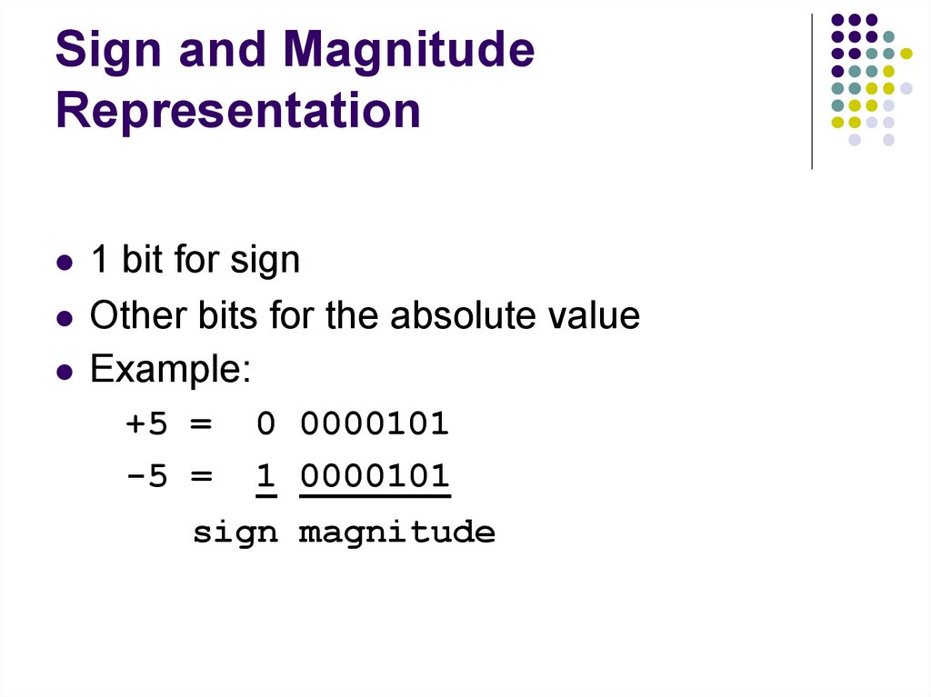
Sign and MagnitudeRepresentation
1 bit for sign
Other bits for the absolute value
Example:
+5 =
-5 =
0 0000101
1 0000101
sign magnitude
128. 1-Complement
Negative numbers are obtained by invertingall bits.
Example:
+5 =
-5 =
00000101
11111010
129. 2-Complement
Negative numbers are obtained bysubtracting 1 from the positive number and
inverting the result.
Example:
+5 =
-5 =
00000101
00000101
-00000001
00000100
11111011
+5 +(-5):
00000101
+11111011
00000000
(ignoring overflow)
130. 2-Complement
2 complement representation is widely usedbecause the same piece of hardware used
for positive numbers can be used for negative
numbers:
+5 +(-3):
Example:
+5 = 00000101
-3 = 00000011
-00000001
00000010
11111101
00000101
+11111101
00000010 (2)
(ignoring overflow)
131. Shift Operator and Signed ints
When signed numbers are shifted right, thesign number is extended to the int shifted:
E.g. int x = -5; // x = 111111…111011
int y = (x >> 1);
// y = 1111111111…111101
x = 5; // x = 00000000000101
y = (x >> 1);
// y = 00000000…0000010
With unsigned ints, a 0 is always inserted at the
132.
Floating Point RepresentationStore both the exponent and mantissa
Example:
3.5x10⁻¹⁶
In binary the representation uses base 2
instead of base 10
Example:
1.101x2-010
133.
Floating Point RepresentationThe most common is the IEEE-754 standard
Float:
e
s
m
23
31
bias = 127
0
Double:
s
63
e
m
52
bias = 1023
0
Val = (-1)s x (1.m) x 2(e-bias)
Notice that the 1 in 1.m is always assumed. The only exception of all the
numbers is 0, that is represented with an exponent of 0.
134.
Floating Point RepresentationExample
Double value in memory (in hex):
4024 0000 0000 0000
Binary:
0100 0000 0010 0100 0000 0000 0000 0000
Decimal?
s (bit 63) = 0 = positive number
e (bits 52 to 62) = 100 0000 0010 = 1024 + 2 = 1026
m (bits 0 to 51) = .0100 0000 0000 0000 0000
Val = (-1)0 x (1.01)b x 2 (1026-1023)
= 1x (20+2-2)x23=(1+1/4)x8=8+2=10
135. Byte Order
There are two byte orders:Little Endian – Least significant byte of the integer
is in the lowest memory location.
Big Endian – Most significant byte of the integer is
in the lowest
136.
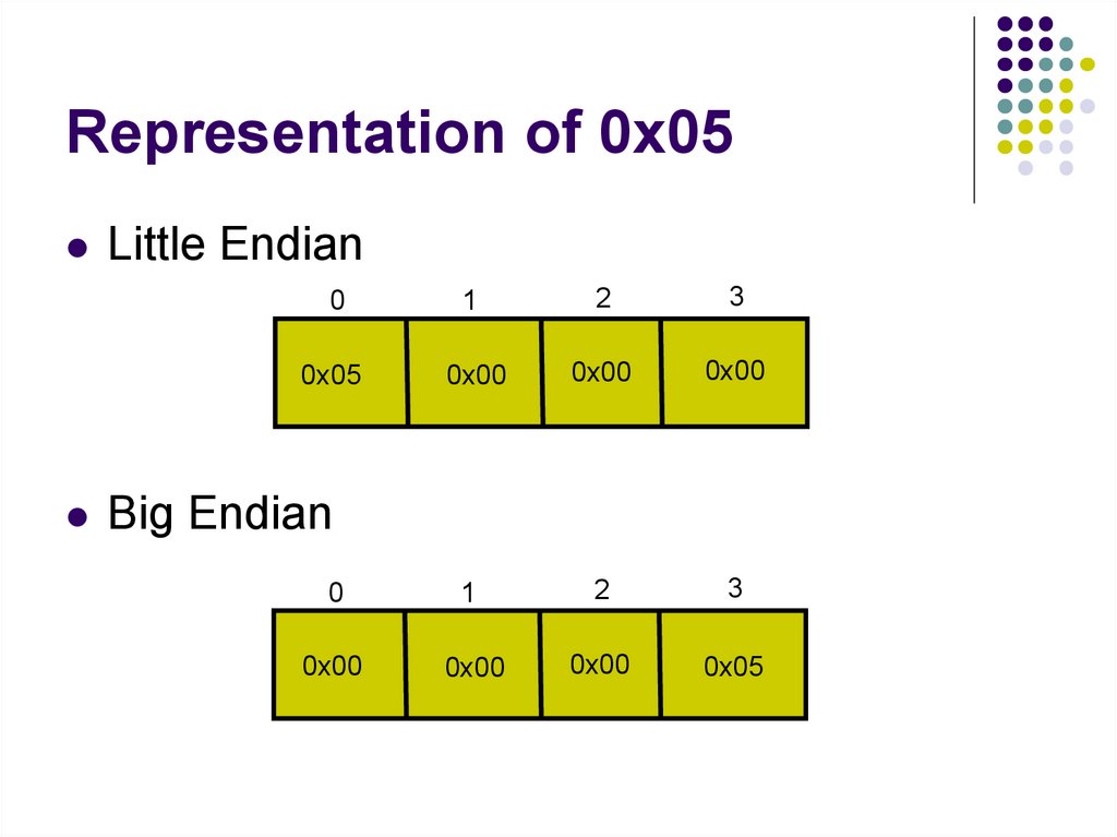
Representation of 0x05Little Endian
0
1
2
3
0x05
0x00
0x00
0x00
Big Endian
0
1
2
3
0x00
0x00
0x00
0x05
137. How to know if it is Little or Big Endian
int isLittleEndian(){
int i = 5;
char * p = (char *) &i;
if (*p==5) {
return 1;
}
return 0;
}
138. Structures
Structures are a combination in memory of primitivetypes.
S:0x100
Example:
0x101
i
0x102
struct {
0x103
int i;
0x104
0x105
r
float r;
0x106
char * a;
0x107
0x108
} s;
0x109
0x10A
0x10B
a
139. Structures and Alignment
Integers, floats, and pointers have to be aligned to 4bytes (in a 32 bit architecture).
Doubles have to be aligned to 8 bytes.
This means that the memory address have to be a multiple
of 4, that is, the last hex digit of the address has to be 0, 4,
8, or C.
This means that the memory address have to be a multiple
of 8, that is, the last hex digit of the address has to be 0, or
8.
If they are not aligned, the CPU will either get an
“bus error” or slow down the execution when trying
to access this data.
140. Example of Alignment in Structures
Example:struct {
char ch1;
int r;
char ch2;
char * a;
} x;
x:0x100
0x101
0x102
0x103
0x104
0x105
0x106
0x107
0x108
0x109
0x10A
0x10B
0x10C
0x10D
0x10E
0x10F
ch1
r
ch2
a
141. IV. Variety of Processors
142. Von Neumann Architecture
Modern processors follow this designPrograms are stored in memory, in the same
way data is stored in memory.
In the early days, before the “Stored
Program” concept, computers had to be
“rewired” in order to run a different program.
In those old days, often took weeks to load a
different program.
143. Von Neumann Architecture
A computer has an address bus and a databus that are used to transfer data from/to the
CPU, RAM, ROM, and the devices.
The CPU, RAM, ROM, and all devices are
attached to this bus.
144. Von Newman Architecture
USBControler
(mouse, kbd)
CD/DVD
Drive
Hard
Drive
Data bus
Address bus
Interrupt Line
CPU
RAM
ROM
Ethernet
Card
145. Processors
Digital device that performs computation usingmultiple steps.
Types of Processors:
Fixed Logic – Least powerful. Single Operation.
Selectable Logic – Performs more than one operation.
Parameterized Logic Processor – Accepts a set of
parameters in the computation.
Programmable Logic Processor – Greatest Flexibility.
Function to compute can be changed. CPU’s belong to this
type of processors.
CPU – Central Processing Unit
146. Components of a CPU
ControllerALU – Arithmetic and Logical Unit
Registers - Local Data Storage
Internal Interconnections
External Interface
147. Components of the CPU
Internal ConnectionsController
ALU
Registers
External Interface
Address Bus
Data Bus
148. Components of the CPU
ControllerControls the execution
Initiates the sequence of steps
Coordinates other components
ALU – Arithmetic and Logical Unit
It provides the Arithmetic and Boolean
Operations.
It performs one operation at a time.
149. Components of the CPU
RegistersInternal Connections
Holds arguments and results of the operations
Transfers values across the components in the
CPU.
External Interface
Provides connections to external memory as well
as I/O devices
150. ALU – Arithmetic Logic Unit
It is the part of the CPU that performs theArithmetic and Boolean operations
Integer Arithmetic - add, subtract, multiply, divide
Shift - left, right, circular
Boolean - and, or, not, exclusive or
151. Processor Categories
CoprocessorsMicrocontroller
Operates in conjunction with other processor.
Example: Floating Point Accelerator.
Small programmable device. Dedicated to control
a physical system. Example: Electronic Toys.
Microsequencer
Use to control coprocessors, memory and other
components inside a larger processor board.
152. Processor Categories
Embedded System ProcessorIt is able to run sophisticated tasks
More powerful than a microcontroller
Example: The controller in a an MP3 player that
includes User Interface and MP3 decoding.
General Purpose Processor
Most powerful type of processor
Completely Programmable
Example: Pentium processor
153. Evolution of Processor Technologies
Discrete LogicSingle circuit board
Use TTL Gates etc used to implement processor.
It could use multiple boxes and circuit boards.
Multiple chips/controllers in a single board.
Single chip
All the components are in a single chip.
154. Fetch-Execute Cycle
This is the basics for programmableprocessors.
It allows moving through the program steps a
while (1) {
Fetch from memory the next instruction to
execute in the program.
Execute this instruction.
}
155. Clock Rate and Instruction Rate
Clock rateIt is the rate at which gates and hardware
components are clocked to synchronize data
transfer.
Instruction rate
It is the time required to execute an instruction.
Different instructions may take different times.
Example: Multiplication and division will take more
clock cycles than addition and subtraction.
156. Starting a Processor
When the CPU is powered on or when resetThe CPU is initialized
The fetch-execute cycle starts.
The first instruction to execute will be in a known
memory location, E.g. 0x1000
This process is called “bootstrap”.
157. Stopping a Processor
When the application finishes or it is waitingfor an event,
The program may enter an infinite loop.
In an OS, that infinite loop is often called
“Null Process” or
“System Idle Process”.
158. V. Processor Types and Instruction Sets
159. How to Choose an Instruction Set
A small set is easy to implement butinconvenient for programmers.
A large set is convenient for programmers but
expensive to implement.
When designing an instruction set we need to
consider
Physical size of the Processor
How the processor will be used
Power consumption
160. Parts of an Instruction
OpcodeOperands
Specifies the instruction to be executed
Specifies the registers, memory location, or
constants used in the instruction
Result
Specifies the registers or memory location where
the result of the operation will be placed.
Opcode
Operand1
Operand2
Result
161. Instruction Length
Fixed LengthEvery instruction has the same length
Reduces the complexity of the hardware
Potentially, the program will run faster.
Variable Length
Some instructions will take more space than others
It is appealing to Assembly code programmers (Not a very
strong advantage. Most programs are written in a highlevel language).
More efficient use of memory.
Pentium continues using variable length instructions
because of backward-compatibility issues.
162. General Purpose Registers
They are used to store operands and resultsEach register has a small size: 1 byte, 4
bytes, or 8 bytes.
Floating Point Registers
Special registers used to store floating point
numbers.
163. Example of Using Registers
Load A from location 0x100 and B from location 0x104. StoreA+B in C in location 0x108 (C=A+B);
load r1, @0x100
load r2, @0x104
add r1, r2, r3
store r3, @0x108
Register Spilling – Save registers in memory for later use. The
number of registers is limited, so very often it is necessary to use
memory or the stack to store temporal values.
Register allocation. Choose what values to keep in the registers
instead of memory.
164. Types of Instruction Sets
CISCComplex Instruction Set Computer
RISC
Reduced Instruction Set Computer
165. CISC Instruction Set
It contains many instructions, often hundreds.Some instructions take longer than others to
complete
Examples:
Move a range of bytes from one place in memory
to another
Compute the length of a string
Example: x86
166. RISC Instruction Set
It contains few instructions 32 or 64Instructions have a fixed length
Each instruction is executed in one clock
cycle.
Example: Sparc, Alpha, MIPS, ARM
167. Execution Pipeline
Hardware optimization techniqueAllows the execution of instructions in
parallel.
Used by RISC architectures
168. Execution Pipeline
An instruction is executed by the followingsteps:
Fetch the next instruction
Examine the opcode to determine the operands
needed.
Fetch the operands
Perform the specified operation
Store the result in the indicated location
Pipelining executes this steps in parallel for
multiple instructions.
169. Execution Pipeline
Stage 1Stage 2
Stage 3
Stage 4
Fetch
Instruction
Examine
Opcode
Fetch
Operands
Perform
Operation
Stage 5
Store
Result
170. Execution Pipeline
Each stage operate in parallel with a differentinstruction.
As a result, an N stage pipeline operates over
N instructions simultaneously.
Each stage takes one clock cycle.
Each instruction takes one clock cycle once
the pipeline is full.
171. Pipeline Example
ClockStage1
Stage2
Stage3
Stage4
Stage5
1
Inst1
2
Inst2
Inst1
3
Inst3
Inst2
Inst1
4
Inst4
Inst3
Inst2
Inst1
5
Inst5
Inst4
Inst3
Inst2
Inst1
6
Inst6
Inst5
Inst4
Inst3
Inst2
7
Inst7
Inst6
Inst5
Inst4
Inst3
8
Inst8
Inst7
Inst6
Inst5
Inst4
9
Inst9
Inst8
Inst7
Inst6
Inst5
172. Pipeline Control
The pipeline is executed by the processorwithout the programmers intervention.
The programmer can write code that can
“stall” the pipeline
That will happen if the next instruction
depends on the result of the previous
instruction.
173. Example of a pipe stall
Assume the following operations:Instruction K:
C <= add A B
Instruction K+1: D <= sub E C
The instruction K+1 needs the result of
instruction K before it can continue.
This causes instruction K+1 to wait until
instruction k completes.
174. Example of a pipe stall
ClockStage1
Stage2
Stage3
Stage4
Stage5
1
Instk
instk-1
instk-2
instk-3
instk-4
2
Instk+1
Instk
instk-1
instk-2
instk-3
3
Instk+2
Instk+1
Instk
instk-1
instk-2
4
Instk+3
Instk+2
(Instk+1)Instk
instk-1
5
-------
-------
(Instk+1)------
Instk
6
-------
-------
Instk+1
------
-------
7
Instk+4
Instk+3
Instk+2
Instk+1
-------
8
Instk+5
Instk+4
Instk+3
Instk+2
Instk+1
9
Instk+6
Instk+5
Instk+4
Instk+3
Instk+2
175. Pipe Stall
Some reasons of a pipe stall are:Access to RAM
Call an instruction that takes along time like FP
arithmetic
Branch to a new location
Call a function
176. Avoiding Pipe Stalls
A programmer can delay the use of results byreordering the instructions:
177. Avoiding Stalls
Program must be written to accommodateinstruction pipeline
To minimize stalls
– Avoid introducing unnecessary branches
– Delay references to result register(s)
178. Avoiding Stalls
ExampleOf Avoiding Stalls
(a)
C add A B
D subtract E C
F add G H
J subtract I F
M add K L
P subtract M N
(b)
C add A B
F add G H
M add K L
D subtract E C
J subtract I F
P subtract M N
Stalls eliminated by rearranging (a) to (b)
179. Avoiding Stalls
Although hardware that uses an instructionpipeline will not run at full speed unless
programs are written to accommodate the
pipeline, a programmer can choose to ignore
pipelining and assume the hardware will
automatically increase speed whenever
possible.
180. VII. CPUs Microcode Protection and Protection Modes
181. User and Kernel Mode, Interrupts, and System Calls
182. Computer Architecture Review
Most modern computers use the VonNewman Architecture where both programs
and data are stored in RAM.
A computer has an address bus and a data
bus that are used to transfer data from/to the
CPU, RAM, ROM, and the devices.
The CPU, RAM, ROM, and all devices are
attached to this bus.
183. Computer Architecture Review
USBControler
(mouse, kbd)
CD/DVD
Drive
Hard
Drive
Data bus
Address bus
Interrupt Line
CPU
RAM
ROM
Ethernet
Card
184. Kernel and User Mode
Kernel ModeWhen the CPU runs in this mode:
It can run any instruction in the CPU
It can modify any location in memory
It can access and modify any register in the CPU and
any device.
There is full control of the computer.
The OS Services run in kernel mode.
185. Kernel and User Mode
User ModeWhen the CPU runs in this mode:
The CPU can use a limited set of instructions
The CPU can only modify only the sections of memory
assigned to the process running the program.
The CPU can access only a subset of registers in the CPU
and it cannot access registers in devices.
There is a limited access to the resources of the computer.
The user programs run in user mode
186. Kernel and User Mode
When the OS boots, it starts in kernel mode.In kernel mode the OS sets up all the interrupt
vectors and initializes all the devices.
Then it starts the first process and switches to user
mode.
In user mode it runs all the background system
processes (daemons).
Then it runs the user shell or windows manager.
187. Kernel and User Mode
User programs run in user mode.The programs switch to kernel mode to request OS
services (system calls)
Also user programs switch to kernel mode when an
interrupt arrives.
The interrupts are executed in kernel mode.
The interrupt vector can be modified only in kernel
mode.
Most of the CPU time is spent in User mode
188. Kernel and User Mode
User ModeKernel Mode
189. Kernel and User Mode
Separation of user/kernel mode is used for:Security: The OS calls in kernel mode make sure that the
user has enough privileges to run that call.
Robustness: If a process that tries to write to an invalid
memory location, the OS will kill the program, but the OS
continues to run. A crash in the process will not crash the
OS. > A bug in user mode causes program to crash, OS
runs. A bug in kernel mode may cause OS and system to
crash.
Fairness: OS calls in kernel mode to enforce fair access.
190. Interrupts
An interrupt is an event that requires immediateattention. In hardware, a device sets the interrupt
line to high.
When an interrupt is received, the CPU will stop
whatever it is doing and it will jump to to the
'interrupt handler' that handles that specific interrupt.
After executing the handler, it will return to the same
place where the interrupt happened and the
program continues. Examples:
move mouse
type key
ethernet packet
191. Steps of Servicing an Interrupt
1.2.
3.
4.
5.
The CPU saves the Program Counter and registers
in execution stack
CPU looks up the corresponding interrupt handler
in the interrupt vector.
CPU jumps to interrupt handler and run it.
CPU restores the registers and return back to the
place in the program that was interrupted. The
program continues execution as if nothing
happened.
In some cases it retries the instruction the
instruction that was interrupted (E.g. Virtual
memory page fault handlers).
192. Running with Interrupts
Interrupts allow CPU and device to run inparallel without waiting for each other.
1. OS Requests
Device Operation
(E.g.Write to disk)
2. OS does other
things in parallel
with device.
2. Device Runs
Operation
3. When Operation is
4. OS services interrupt complete interrupt
OS
and continues
193. Poling
Alternatively, the OS may decide not use interrupts forsome devices and wait in a busy loop until completion.
OS requests Device operation
While request is not complete
do nothing;
Continue execution.
This type of processing is called “poling” or “busy
waiting” and wastes a lot of CPU cycles.
Poling is used for example to print debug messages in
the kernel (kprintf). We want to make sure that the
debug message is printed to before continuing the
execution of the OS.
194. Synchronous vs. Asynchronous
Poling is also called SynchronousProcessing since the execution of the device
is synchronized with the program.
An interrupt is also called Asynchronous
Processing because the execution of the
device is not synchronized with the execution
of the program. Both device and CPU run in
parallel.
195. Interrupt Vector
It is an array of pointers that point to thedifferent interrupt handlers of the different
types of interrupts.
Hard Drive Interrupt handler
USB Interrupt handler (mouse, kbd)
Ethernet Card Interrupt handler
Page Fault Interrupt handler
196. Interrupts and Kernel Mode
Interrupts run in kernel mode. Why?An interrupt handler must read device/CPU
registers and execute instructions only
available in kernel mode.
Interrupt vector can be modified only in
kernel mode (security)
Interrupt vector initialized on bootup;
modified when drivers added to system
197. Types of Interrupts
1. Device Interrupts generated by Deviceswhen a request is complete or an event that
requires CPU attention happens.
The mouse is moved
A key is typed
An Ethernet packet arrives.
The hard drive has completed a read/write
operation.
A CD has been inserted in the CD drive.
198. Types of Interrupts
2. Math exceptions generated by the CPU whenthere is a math error.
Divide by zero
3. Page Faults generated by the MMU (Memory
Management Unit) that converts Virtual memory
addresses to physical memory addresses
Invalid address: interrupt prompts a SEGV signal to the
process
Access to a valid address but there is not page in
memory. This causes the CPU to load the page from
disk
Invalid permission (I.e. trying to write on a read only
page) causes a SEGV signal to the process.
199. Types of Interrupts
4. Software Interrupt generated by softwarewith a special assembly instruction. This is
how a program running in user mode
requests operating systems services.
200. System Calls
System Calls is the way user programs requestservices from the OS
System calls use Software Interrupts
Examples of system calls are:
open(filename, mode)
read(file, buffer, size)
write(file, buffer, size)
fork()
execve(cmd, args);
System calls is the API of the OS from the user program’s point
of view. See /usr/include/sys/syscall.h
201. Why do we use Software Interrupts for syscalls instead of function calls?
Software Interrupts will switch into kernelmode
OS services need to run in kernel mode
because:
They need privileged instructions
Accessing devices and kernel data structures
They need to enforce the security in kernel mode.
202. System Calls
Only operations that need to be executed by the OSin kernel mode are part of the system calls.
Function like sin(x), cos(x) are not system calls.
Some functions like printf(s) run mainly in user mode
but eventually call write() when for example the
buffer is full and needs to be flushed.
Also malloc(size) will run mostly in user mode but
eventually it will call sbrk() to extend the heap.
203. System Calls
Libc (the C library) provides wrappers for thesystem calls that eventually generate the
system calls.
Kernel Mode:
User Mode:
int open(fname, mode) {
return syscall(SYS_open,
fname, mode);
}
int syscall(syscall_num, …)
{
Software
asm(INT);
}
Interrupt
Syscall interrupt handler:
Read:…
Write:…
open:
- Get file name and mode
- Verify permissions of
file against mode.
- Perform operation
- return fd (file
descriptor)
204. System Calls
The software interrupt handler for systemcalls has entries for all system calls.
The handler checks that the arguments are
valid and that the operation can be executed.
The arguments of the syscall are checked to
enforce the security and protections.
205. Syscall Security Enforcement
For example, for the open syscall the following ischecked in the syscall software interrupt handler:
open(filename, mode)
If file does not exist return error
If permissions of file do not agree with the mode the file
will be opened, return error. Consider also who the owner
of the file is and the owner of the process calling open.
If all checks pass, open file and return file handler.
206. Syscall details
Te list of all system calls can be found in/usr/include/sys/syscall.h
#define
#define
#define
#define
#define
#define
#define
#define
#define
#define
#define
…
SYS_exit
SYS_fork
SYS_read
SYS_write
SYS_open
SYS_close
SYS_wait
SYS_creat
SYS_link
SYS_unlink
SYS_exec
1
2
3
4
5
6
7
8
9
10
11
207. Syscall Error reporting
When an error in a system call occurrs, the OS sets aglobal variable called “errno” defined in libc.so with the
number of the error that gives the reason for failure.
The list of all the errors can be found in
/usr/include/sys/errno.h
#define
#define
#define
#define
#define
#define
EPERM
ENOENT
ESRCH
EINTR
EIO
ENXIO
1
2
3
4
5
6
/*
/*
/*
/*
/*
/*
Not super-user
*/
No such file or directory */
No such process */
interrupted system call */
I/O error */
No such device or address */
You can print the corresponding error message to stderr
using perror(s); where s is a string prepended to the
message.
208. System Calls and Interrupts Example
1.2.
3.
The user program calls the write(fd, buff,
n) system call to write to disk.
The write wrapper in libc generates a software
interrupt for the system call.
The OS in the interrupt handler checks the
arguments. It verifies that fd is a file descriptor for
a file opened in write mode. And also that [buff,
buff+n] is a valid memory range. If any of the
checks fail write return -1 and sets errno to the
error value.
209. System Calls and Interrupts Example
4. The OS tells the hard drive to write the buffer in[buff, buff+n] to disk to the file specified by fd.
5. The OS puts the current process in wait state until
the disk operation is complete. Meanwhile, the OS
switches to another process.
6. The Disk completes the write operation and
generates an interrupt.
7. The interrupt handler puts the process calling
write into ready state so this process will be
scheduled by the OS in the next chance.
210. ARM Assembly Language
211. ARM Architecture
ARM- Acorn RISC MachineARM is an architecture created by “ARM Holdings”
ARM Holdings does not manufacture the CPU’s,
instead it licenses the design to other manufacturers
so they create their own version of ARM.
ARM has become popular because of mobile
computing: Smart phones, tablets etc.
It is energy-efficient, fast, and simple.
It still lags in speed compared to the fastest Intel x86
CPUs but it is more energy efficient.
212. ARM CPUs
Chips using ARM architectureA4, A5, A6, A7
Qualcomm’s Snapdragon
Samsung Galaxy, LG, Nokia Lumia, Sony, Kindle
NVIDIA Tegra
Iphone/Ipad by Apple
Windows RT Tablet, Motorola Droid, Motorola Atrix
Broadcom, BCMXXX CPUs
Samsung Galaxy, Raspberry Pi
213. ARM Assembly Language
See:http://www.cs.purdue.edu/homes/cs250/LectureNotes/arm_inst.pdf
and
http://www.cs.purdue.edu/homes/cs250/LectureNotes/arm-ref.pdf
214. Example Assembly Program
test1.s:.text
.global main
main:
stmfd
ldr
bl
ldmfd
sp!, {fp, lr}
r0, .L2
puts
sp!, {fp, pc}
.word
.LC0
.L2:
.section
.rodata
.LC0:
.ascii
"Hello world\000"
215. Running the Assembler
pi@raspberrypi:~/cs250/lab6-src$ gcc -o test1 test1.spi@raspberrypi:~/cs250/lab6-src$ ./test1
Hello world
pi@raspberrypi:~/cs250/lab6-src$
216. Assembly Code in Hexadecimal
pi@raspberrypi:~/cs250/lab6-src$ gcc -Xassembler -a -o test1 test1.s > outpi@raspberrypi:~/cs250/lab6-src$ vi out
ARM GAS test1.s
page 1
1
2
.text
3
.global main
4
5
main:
6 0000 00482DE9
stmfd
sp!, {fp, lr}
7 0004 04009FE5
ldr
r0, .L2
8 0008 FEFFFFEB
bl
puts
9 000c 0088BDE8
ldmfd
sp!, {fp, pc}
10
.L2:
11 0010 00000000
.word
.LC0
12
13
.section
.rodata
14
.LC0:
15 0000 48656C6C
.ascii "Hello world\000"
15
6F20776F
15
726C6400
The third column is the code generated in hexadecimal.
217. Calling Conventions
r0 to r3:r4 to r11:
Used to hold local variables. (Need to be restored before
return)
r13 is the stack pointer.
They are used to pass arguments to a function. r0 is used
to return values. (No need to be restored before return).
Stores return PC and save registers and local vars.
r14 is the link register. (The BL instruction, used in a
subroutine call, stores the return address in this
register).
r15 is the program counter.
218. Condition Code Flags
This flags are stored in the PSR- ProcessorStatus Register
They are updated by the Arithmetic
Operations
N = Negative result from ALU flag.
Z = Zero result from ALU flag.
C = ALU operation Carried out
V = ALU operation oVerflowed
219. Updating the Condition Code Flags
CMP reg1, reg2TST reg1, reg2
Performs reg1-reg2
It updates N, Z, C, V
No other registers are modified
Performs reg1 bit-and reg2
It updates N,Z
No other registers are modified
Any instruction may modify the flags if “S” is
appended to the instruction:
Example MOVS reg1, reg2 will update N, Z if reg2 is zero
or negative
220. ARM Instructions
ARM assembly language reference cardMOVcdS reg, arg copy argument (S = set ags)
MVNcdS reg, arg copy bitwise NOT of argument
ANDcdS reg, reg, arg bitwise AND
ORRcdS reg, reg, arg bitwise OR
EORcdS reg, reg, arg bitwise exclusive-OR
BICcdS reg, rega, argb bitwise rega AND (NOT argb)
ADDcdS reg, reg, arg add
SUBcdS reg, reg, arg subtract
RSBcdS reg, reg, arg subtract reversed arguments
ADCcdS reg, reg, arg add with carry ag
SBCcdS reg, reg, arg subtract with carry ag
RSCcdS reg, reg, arg reverse subtract with carry ag
CMPcd reg, arg update ags based on subtraction
CMNcd reg, arg update ags based on addition
221. ARM Instructions
TSTcd reg, arg update ags based on bitwise ANDTEQcd reg, arg update ags based on bitwise exclusive-OR
MULcdS regd, rega, regb multiply rega and regb, places lower 32 bits into regd
MLAcdS regd, rega, regb, regc places lower 32 bits of rega · regb + regc into regd
UMULLcdS reg`, regu, rega, regb multiply rega and regb, place 64-bit unsigned result into {regu, reg`}
UMLALcdS reg`, regu, rega, regb place unsigned rega · regb + {regu, reg`} into {regu, reg`}
SMULLcdS reg`, regu, rega, regb multiply rega and regb, place 64-bit signed result into {regu, reg`}
SMLALcdS reg`, regu, rega, regb place signed rega · regb + {regu, reg`} into {regu, reg`}
Bcd imm12 branch to imm12 words away
BLcd imm12 copy PC to LR, then branch
BXcd reg copy reg to PC
SWIcd imm24 software interrupt
LDRcdB reg, mem loads word/byte from memory
STRcdB reg, mem stores word/byte to memory
LDMcdum reg!, mreg loads into multiple registers
STMcdum reg!, mreg stores multiple registers
SWPcdB regd, regm, [regn] copies regm to memory at regn,old value at address regn to regd
Optional:
cd – Condition Code
s – Update flkag or not
b – byte or word instruction
222. ARM Instructions Add-Ons: Conditions
Every instruction may be have a conditionappended:
Example:
MOV r1, r2 and EQ (zero flag set)
becomes
MOVEQ r1,r2
This means that the r2 will be moved to r1 only
if the zero flag is set.
223. List of Conditions that Can be Added to Instructions
AL or omitted alwaysEQ equal (zero)
NE nonequal (nonzero)
CS carry set (same as HS)
CC carry clear (same as LO)
MI minus
PL positive or zero
VS over ow set
VC over ow clear
HS unsigned higher or same
LO unsigned lower
HI unsigned higher
LS unsigned lower or same
GE signed greater than or equal
LT signed less than
GT signed greater than
LE signed less than or equal
224. Example: Adding two numbers
Implement the following program in assembler:#include <stdio.h>
int a;
int b;
int c;
main()
{
a = 2;
b = 3;
c = b + c;
printf("c=%d\n", c);
}
225. Example: Adding two numbers in Assembly using Registers
/* add-reg.sAdding two numbers using registers */
.section
.rodata
printfArg:
.ascii "c=%d\n"
/* Define
int a;
int b;
int c;
*/
variable 4 bytes each aligned to 4 bytes
- r2
- r3
- r1
.text
addrPrintfArg: .word printfArg
226. Adding two numbers in Assembly using Registers (cont.)
.global main/* main() { */
main:
stmfd
sp!, {fp, lr}
/* Save pc and lr */
mov
mov
add
r2, #2
r3, #3
r1, r2, r3
ldr
bl
r0, addrPrintfArg
/* Load printf format in r0 */
/* second argument is in r1 */
/* r1 already has the result of a+b*/
printf
/* printf("c=%d\n", c); */
ldmfd
sp!, {fp, pc}
/* a=2; */
/* b=3; */
/* c = a + b; */
/* return from main */
/* } */
227. Adding two numbers in Assembly using Registers (cont.)
pi@raspberrypi:~/cs250/lab6-src$ gcc -o add-reg add-reg.spi@raspberrypi:~/cs250/lab6-src$ ./add-reg
c=5
228. Example: Adding Two Numbers Using Global Vars
/* add-global.s:Adding two numbers using global variables */
.section
.rodata
printfArg:
.ascii "c=%d\n"
.section .data
.align 2
/* Define variable 4 bytes each aligned to 4 bytes
int a;
int b;
int c;
*/
.comm
a,4,4
.comm
b,4,4
.comm
c,4,4
229. Adding Two Numbers Using Global Vars (cont.)
.text/* We need to store the addresses of a and b
in .text to be able to access them in main */
addra: .word a
addrb: .word b
addrc: .word c
addrPrintfArg: .word printfArg
.global main
/* main() { */
main:
stmfd sp!, {fp, lr}
/* Save pc and lr */
ldr r3, addra
mov r2, #2
str r2, [r3]
/* a = 2; */
ldr r3, addrb
mov r2, #3
str r2, [r3]
/* b = 3; */
230. Adding two numbers using Global Vars (cont.)
ldr*/
r2, addra
ldr
ldr
in r3 */
ldr
add
ldr
str
ldr
in r0 */
ldr
ldr
bl
c); */
ldmfd
/* Read a and put it in r2
r2, [r2]
r3, addrb
/* read b and put it
r3, [r3]
r2, r2, r3
r3, addrc
r2, [r3]
/* c = a + b; */
r0, addrPrintfArg
/* Load printf format
r1, addrc
r1, [r1]
printf
/* Load c in r1 */
/* printf("c=%d\n",
sp!, {fp, pc}
/* return from main */
231. Adding two numbers using Global Vars (cont.)
pi@raspberrypi:~/cs250/lab6-src$ gcc -o add-global add-global.spi@raspberrypi:~/cs250/lab6-src$ ./add-global
c=5
232. Example: Read two numbers and add them
/* readadd.sRead two numbers and add them
pi@raspberrypi:~/cs250/lab6-src$ ./readadd
a: 8
b: 9
c=a+b=17
*/
.section
.rodata
promptA:
.ascii "a: \000"
promptB:
.ascii "b: \000"
readA:
.ascii "%d\000"
readB:
.ascii "%d\000"
printC:
.ascii "c=a+b=%d\n\000"
233. Example: Read two numbers and add them (cont.)
.section .data.align 2
/* Define variable 4 bytes each aligned to 4 bytes
int a;
int b;
*/
.comm
a,4,4
.comm
b,4,4
.text
/* We need to store the addresses of a and b
in .text to be able to access them in main */
addra: .word a
addrb: .word b
addrPromptA: .word promptA
addrPromptB: .word promptB
addrReadA: .word readA
addrReadB: .word readB
addrPrintC: .word printC
234. Example: Read two numbers and add them (cont.)
.global main/* main() { */
main:
stmfd
sp!, {fp, lr}
/* Save pc and lr */
ldr
bl
r0, addrPromptA
printf
/* Prompt a */
ldr
ldr
bl
r0, addrReadA
r1, addra
scanf
/* Read a */
ldr
bl
r0, addrPromptB
printf
/* Prompt b */
ldr
ldr
bl
r0, addrReadB
r1, addrb
scanf
/* Read b */
ldr
ldr
r0, addra
r0, [r0]
/* r0<- a */
235. Example: Read two numbers and add them (cont.)
ldrldr
r1, addrb
r1, [r1]
/* r1<- b */
add
r1, r0, r1
/* r1 <- r1 +r0*/
ldr
bl
r0, addrPrintC
printf
/* print c */
ldmfd
sp!, {fp, pc}
/* return from main */
/* } */
236. Example: Read two numbers and add them (cont.)
pi@raspberrypi:~/cs250/lab6-src$ gcc -oreadadd readadd.s
pi@raspberrypi:~/cs250/lab6-src$ ./readadd
a: 7
b: 4
c=a+b=11
237. Mixing C and Assembly Language. Finding max in an array.
max.c:#include <stdio.h>
#include <stdlib.h>
extern int maxarray(int *a, int n);
main()
{
int n;
int i;
int * a;
printf("How many elements in array? ");
scanf("%d",&n);
a = (int*) malloc(n*sizeof(int));
for (i = 0; i < n; i++) {
printf("a[%d]= ", i);
scanf("%d", &a[i]);
}
int m = maxarray(a, n);
printf("max=%d\n", m);
}
238. Mixing C and Assembly Language. Finding max in an array (cont.)
maxarray.s/* Find maximum of an array of integers. Called from "C"
extern int maxarray(int *a, int n);
*/
.text
*/
.global maxarray
/* maxarray(int *a, int n) {
/* a: r0 */
/* n: r1 */
maxarray:
stmfd
sp!, {r4, r5, fp, lr}
/* Save pc, lr, r4, r5 */
ldr
r2,[r0]
/* max: r2 */
/* max= a[0] */
mov
r3,#0
/* i: r3 */
/* i=0; */
239. Mixing C and Assembly Language. Finding max in an array (cont.)
while:nomax:
cmp
beq
r3,r1
endmax
/* while (i!=n) { */
mov
mov
mul
add
ldr
r4,r3
/* r4=a[i] */
r5,#4
r4,r4,r5
r4,r0,r4 /* as r4=*(int*)((char*)a+4*i)*/
r4,[r4]
cmp
bgt
mov
r2, r4
nomax
r2,r4
/* if (max < r4) max = r4 */
240. Mixing C and Assembly Language. Finding max in an array (cont.)
movadd
r5,#1
r3,r3,r5
/* i++; */
bal
while
/* Go back to while */
mov
r0,r2
ldmfd
sp!, {r4, r5, fp, pc}
/* return from main */
endmax:
/* } */
241. Mixing C and Assembly Language. Finding max in an array (cont.)
pi@raspberrypi:~/cs250/lab6-src$ gcc -o max max.cmaxarray.s
pi@raspberrypi:~/cs250/lab6-src$ ./max
How many elements in array? 6
a[0]= 34
a[1]= 78
a[2]= 34
a[3]= 90
a[4]= 78
a[5]= 45
max=90
242. Implementing String Functions in ARM Assembly Language
There are two functions to load/store bytes:ldrb reg1,[reg2]
Loads in reg1 the byte in address pointed by
reg2
strb reg1,[reg2]
Stores the least significant byte in reg1 byte in
address pointed by reg2
243. Example: strcat function in ARM assembly
/* strcat-main.c:*/#include <stdio.h>
#include <string.h>
extern char * mystrcat(char * a, char *b);
main()
{
char s1[100];
char s2[100];
printf("s1? ");
gets(s1);
printf("s2? ");
gets(s2);
mystrcat(s1, s2);
printf("s1+s2=%s\n", s1);
}
//
//
//
//
//
//
//
Implemented in Assembly Language in mystrcat.s
Shown here to teach you the algorithm used.
char * mystrcat(char * a, char *b) {
while (*a) a++;
while (*b) { *a=*b; a++; b++;}
*a=0;
}
244. Example: strcat function in ARM assembly (cont.)
/* Concat two strings a, b. Result is in a.extern char * mystrcat(char *a, char *b);
*/
.text
.global mystrcat
/* a: r0 */
/* b: r1 */
mystrcat:
stmfd sp!, {r4, fp, lr}
/* Save pc, lr, r4*/
/* Skip chars in a */
skip:
ldrb r2,[r0]
mov r3,#0
cmp r2,r3
beq endskip
mov r3,#1
add r0,r0,r3
bal skip
endskip:
/* r2 <- *a */
/* if (*a == 0) jump endskip */
/* a++ */
/* go to skip */
245. Example: strcat function in ARM assembly (cont.)
skip2:ldrb r4,[r1]
mov r3,#0
cmp r4,r3
beq endcat
strb r4,[r0]
mov r3,#1
add r0,r0,r3
add r1,r1,r3
bal skip2
endcat:
mov r3, #0
strb r3, [r0]
ldmfd sp!, {r4, fp, pc}
/* Add char by char *b to *a until we find the end of *b */
/* r4 <- *b */
/* if (*b == 0) jump endcat */
/* *a = *b; */
/* a++ */
/* b++ */
/* go to skip2 */
/* *a = 0; */
/* return from mystrcat */
246. Example: strcat function in ARM assembly (cont.)
pi@raspberrypi:~/cs250/lab6-src$ gcc -o strcat-main strcat-main.cmystrcat.s
pi@raspberrypi:~/cs250/lab6-src$ ./strcat-main
s1? Hello
s2? World
s1+s2=HelloWorld
pi@raspberrypi:~/cs250/lab6-src$
247. Midterm Review
248. Midterm Review
II. Fundamentals of Digital LogicVoltage and Current
Boolean Logic
Truth Tables
Implementation using Logical gates.
Implementing an add circuit.
Flip-Flops
Karnaugh Maps
249. Midterm Review
III. Data and program RepresentationMemory of a Program
Memory Sections:
Executable File formats
Steps for building a program:
text, Data, Bss, Heap, Stack Shared Libraries
C preprocessor, Compiler, Optimizer, Assembler,
Linker.
Steps for loading a program
Static and Shared libraries
250. Midterm Review
III. Data and program Representation (cont.)Binary Addition , Subtraction, Multiplication and Division
Sign representation:
Sign and Magnitude, Complements of 1 and 2
Floating Point Representation
Byte Order
Little Endian
Big Endian
Structures and alignment
ASCII and Unicode and String representation
251. Midterm Review
IV. Variety of ProcessorsVon Neumann Architecture
Address Bus and Data Bus
Components of the CPU
Fetch Execute Cycle
252. Midterm Review
V. Processor Types and Instruction SetsCISC and RISC
Execution Pipeline
Pipe Stall
VI. Operand Addressing and Instruction
Representation
0 address architecture, 1 address architecture, 2
address architecture and 3 address architecture.
Von Neumann Bottleneck
253. Midterm Review
VI. Operand Addressing and InstructionRepresentation (cont.)
Addressing modes:
Immediate, Direct, Indirect
VII. CPUs Microcode Protection and
Protection Modes
Kernel and User Mode
Promotes Security, Robustness and Fairness
254. Midterm Review
VII. CPUs Microcode Protection and ProtectionModes
Interrupts
Steps to service an interrupt
Asynchronous Processing
Poling
Interrupt Vector
Types of Interrupts:
Device Interrupts, Math exceptions, Page Faults, Software
Interrupts.
System Calls
255. Midterm Review
MicrocodeVertical and Horizontal Microcode
VIII. Assembly Language and Programming
Paradigm
ARM Assembly language
256. Midterm Material to Study
Class SlidesMidterm Exam Homework Review
Projects Lab1-Lab6
ARM Assembly Language
Everything up to and including chapter ”VIII
Memory and Storage” in the book.
I will include the “Reference Card ARM
Assembly Language” in the exam.
257. X86-64 Asembly Language
258. History
Created by AMD to extend the x86architecture to use 64 bits
X86-64 is a superset of x86
It has been adopted by Intel
It provides an incremental evolution to
migrate from x86-32 bits to x86-64 bits.
259. Register Assignment
(Bryant/O’Hallaron “x86-Machine Level Programming”)260. Using registers
A function can use any of the argumentregisters. There is no need to save them.
If a function uses any of the “callee saved”,
registers it has to save them in the stack and
then restore them before returning to the
caller.
261. X86-64 C-Types
(Bryant/O’Hallaron “x86-Machine Level Programming”)262. Addressing modes
Immediate Valuemovq $0x501208,%rdi
#Put in register %rdi the
# constant 0x501208
Direct Register Reference
movq %rax,%rdi
#Move the contents of
#register %rax to %rdi
Indirect through a register
movq %rsi,(%rdi)#Store the value in %rsi
#in the address contained in %rdi
Direct Memory Reference
movq 0x501208,%rdi #Fetch the contents in memory
#at address 0x501308 and store it
#in %edi
263. Example: Adding two numbers
.textsum:
movq
addq
ret
%rdi, %rax
%rsi, %rax
# int sum(int a, int b) {
#
// a=%rdi b=%rsi ret=%rax
#
return a + b ;
# }
str1:
.string "5+3=%d\n"
.globl main
main:
movq
movq
call
movq
movq
movq
call
ret
$3, %rsi
$5, %rdi
sum
%rax, %rsi
$str1, %rdi
$0, %rax
printf
# main()
# {
#
// r = %rax
#
r = sum(5, 3)
#
#
#
// printf needs 0 in %rax
#
printf("5+3=%d\n", r);
# }
264. Assembling and running
To assemble and run program:$sslab01 ~/cs250 $ gcc -o t1 t1.s
$sslab01 ~/cs250 $ ./t1
5+3=8
Notice that in the previous example we use quad
words during the arithmetic even though the type is
int.
Most of the time there is no penalty for doing that
and it makes programs simpler.
265. Using the stack
The stack is used tostore the return address
store local variables
Save registers when running out of them.
pass arguments when they don’t fit in the
registers.
266. Example of Using Stack
long sum(long a, long b){
long tmp1 = a;
long tmp2 = b;
long result = tmp1 + tmp2;
return result;
}.
main()
{
long result = sum(5,3);
printf("sum(5,3)=%d\n", sum(5,3));
}
267. Stack Layout
Before calling sum:%rsp
main() ret address
0
After calling sum:
main() ret address
%rsp
8
sum() ret address
0
In sum after subq $24, %rsp:
main() ret address
sum() ret address
%rsp
tmp1
tmp2
result
16
8
0
268. Example of Using Stack
.text.globl sum
.type
sum:
subq
sum, @function
$24, %rsp
# Create space in stack for
# tmp1, tmp2 and result
movq
movq
%rdi, 16(%rsp)
%rsi, 8(%rsp)
# tmp1 = a
# tmp2 = b
movq
addq
movq
16(%rsp), %rax
8(%rsp), %rax
%rax, (%rsp)
# result = tmp1 + tmp2 ;
movq
(%rsp), %rax
# return result ;
addq
$24, %rsp
# Restore stack pointer
ret
269. Using flow control
To test the difference conditions use:cmpq S2, S1
# S1 – S2: Compare quad words
or
testq S2, S1
# S1 & S2: Test Quad Word
270. Example of if statement: Obtaining maximum of two numbers
long max(long a, long b){
long result;
if (a > b) {
result = a;
}
else {
result = b;
}
return result;
}
271. Example of “if” statement: Obtaining maximum of two numbers
.text.globl max
max:
cmpq
jle
movq
jmp
else_branch:
movq
end_max:
ret
%rsi, %rdi
else_branch
%rdi, %rax
end_max
%rsi, %rax
# if (a>b)
#
result = a
# else
#
result = b
# return result
272. Example of “while” statement: Obtaining the maximum of an array of numbers.
// Finds the max value in an arraylong maxarray(long n, long *a) {
long i=0;
long max = a[0];
while (i<n) {
if (max < *a) {
max = *a
}
i++ ;
a++ ;
}
return max;
}
273. Example of “while” statement: Obtaining the maximum of an array of numbers.
maxarray.s.text
.globl maxarray
maxarray:
movq
movq
while: cmpq
jle
cmpq
jge
movq
afterif:
addq
addq
jmp
afterw: ret
$0,%rdx
(%rsi),%rax
%rdx,%rdi
afterw
(%rsi),%rax
afterif
(%rsi),%rax
$1,%rdx
$8,%rsi
while
# long maxarray(long n, long *a)
#
// n = %rdi
a = %rsi
#
// i = %rdx
max = %rax
#
#
i=0 ;
#
max = a[0];
#
#
while (i<n) { // (n-i>0)
#
#
#
if (max < *a) { // (max-*a<0)
#
#
max = *a
#
}
#
#
i++ ;
#
a++ ;
#
}
# return max; }
274. Example of “while” statement: Obtaining the maximum of an array of numbers using Array Dereferencing
// Finds the max value in an arraylong maxarray(long n, long *a) {
long i=0;
long max = a[0];
while (i<n) {
if (max < a[i]) {
max = a[i];
}
i++ ;
}
return max;
}
275. Same program using array dereferencing
.text.globl maxarray
maxarray:
while:
movq
movq
$0,%rdx
(%rsi),%rax
cmpq
jle
%rdx,%rdi
afterw
movq
imulq
addq
%rdx,%rcx
$8,%rcx
%rsi,%rcx
cmpq
jge
movq
(%rcx),%rax
afterif
(%rcx),%rax
afterif:addq
jmp
afterw: ret
$1,%rdx
while
# // Finds the max value in an array
#
# long maxarray(long n, long *a)
#
// n = %rdi
a = %rsi
#
// i = %rdx
max = %rax
#
#
i=0 ;
#
max = a[0]
#
#
while (i<n) { // (n-i>0)
#
#
//*(long*)((8*i+(char*)a)
#
long *tmp = a[i];
#
#
#
#
if (max < *tmp) { // (max-*tmp<0)
#
#
max = *tmp
#
}
#
i++ ;
#
#
}
# }
276. Running the program
maxarray.c:long a[] = {4, 6, 3, 7, 9 };
main()
{
printf("maxarray(5,a)=%d\n", maxarray(5,a));
}
grr@sslab01 ~/cs250 $ gcc -o maxarray maxarray.c maxarray.s
grr@sslab01 ~/cs250 $ ./maxarray
maxarray(5,a)=9
grr@sslab01 ~/cs250 $
277. Defining Global Variables in Assembly Language
To create space for a global variable in assembly language use:.data
.comm <var-name>, <data-size>[,<alignment>]
where
<var-name> = variable name
<data-size> = Size of variable in bytes
<alignment> = Optional alignment. Address of variable will be a multiple
of alignment. Otherwise alignment will be a power of 2 larger to
data-size up to 32.
Example:
.data
.comm a,8
# long a;
.comm array,40
# long a[5];
.comm darray, 80,8 # double darray[10];
278. Example Using scanf in x86-64 assembler
# Define global variable a in data section.data
.comm a,8
# long a;
.text
format1:
.string
"a="
format2:
.string
"%ld"
format3:
.string
"a is %ld\n"
.globl main
main:
# main()
movq
movq
call
#
$format1, %rdi # printf("a=");
$0, %rax
#
printf
#
movq
movq
movq
call
$format2, %rdi # scanf("%ld",&a);
$a, %rsi
#
$0, %rax
#
scanf
#
movq
movq
movq
movq
call
$format3, %rdi # printf("a=%ld",a);
$a, %rsi
#
(%rsi),%rsi #
$0, %rax
#
printf
#
ret
#}
279. Using gdb with assembly programs
Use the following instructions to debugassembly programs:
stepi – steps in the next instruction. If this is a
“call” instruction, it steps in the called function.
nexti – Executes next instruciton. It does not enter
into a called funciton.
disassemble function/label– disassembles the
current function or label
Break function – Sets a break point in a function
Run – run to completion or until a breakpoint
280. Using gdb
(gdb) break mainBreakpoint 1 at 0x4004f4
(gdb) run
Starting program: /u/u3/grr/cs250/max
warning: no loadable sections found in added symbol-file system-supplied DSO at 0x7ffff01fe000
Breakpoint 1, 0x00000000004004f4 in main ()
(gdb) stepi
0x00000000004004f9 in main ()
(gdb)
0x00000000004004fe in main ()
(gdb)
0x0000000000400503 in main ()
(gdb)
0x000000000040051c in maxarray ()
(gdb)
0x0000000000400523 in maxarray ()
(gdb) disassemble
Dump of assembler code for function maxarray:
0x000000000040051c <maxarray+0>:
mov
0x0000000000400523 <maxarray+7>:
mov
End of assembler dump.
(gdb)
$0x0,%rdx
(%rsi),%rax
281. Lab7: Writing a Simple Compiler
In this lab you will write a compiler for “SimpleC”
This language is a reduced version of “C”.
We will concentrate on generating the
assembly language code.
We will cover superficially the theory of
parsing and the use of Lex and Yacc
282. Simple C
Subset of COnly the following types are supported:
long
long*
char
char*
void
Also it supports constructions such as if/else, while, do/while, for.
The program consists of a declaration of functions and variables
like in “C”.
Also you can call “C” functions from Simple C as long as the
arguments they use are char* and long (or int).
283. Example Simple “C” program
long fact(long n) {if (n==0) return 1;
return n*fact(n-1);
}
void main()
{
printf("Factorial of 5 = %d\n" , fact(5));
}
284. Building a Compiler
To help in the development of compilers,tools such as Lex and Yacc have been
created.
With these tools, the programmer
concentrates only in the grammar and the
code generation.
285. Lex
Lextakes as input a file simple.l with the regular
expressions that describe the different tokens.
It generates a scanner file “lex.yy.c” that reads
characters and forms tokens or words that the
parser uses.
286. Yacc
YaccTakes as input a file simple.y with the grammar
that describes the language.
This file also contains “actions” that is “C” code
that describes how the code will be generated
while parsing the code.
It generates a parser file called “y.tab.c” that
reads the tokens and parses the program
according to the syntax.
When it reaches an action in the syntax tree, it
executes that action
287. Lex and Yacc Interaction
Input file:test1.c
chars:
m a i n ( i n t
a)
Scanner
Parser
simple.l
simple.y
(lex.yy.c)
(y.tab.c)
Output File:
test1.s
.text
.globl main
main:
Tokens:
WORD LPARENT INT WORD RPARENT
lex simple.l
yacc simple.y
lex.yy.c
y.tab.c
288. Lex Input file simple.l
It contains the regular expressions thatdescribe the different tokens
"return" {
return RETURN;
}
[A-Za-z][A-Za-z0-9]* {
/* Assume that file names have only alpha chars */
yylval.string_val = strdup(yytext);
return WORD;
}
289. Yacc input file simple.y
It contains the grammar that describes thelanguage.
It also contains actions or c code that will be
executed after parsing specific grammar
constructions.
It also includes the main() entry point of the
compiler.
290. Yacc input file simple.y
program :function_or_var_list;
function_or_var_list:
function_or_var_list function
| function_or_var_list global_var
| /*empty */
;
function:
var_type WORD
{
fprintf(fasm, "\t.text\n");
fprintf(fasm, ".globl %s\n", $2);
fprintf(fasm, "%s:\n", $2);
}
LPARENT arguments RPARENT compound_statement
{
fprintf(fasm, "\tret\n");
}
;
291. Code generation
You will need to add more actions to generate thecode.
An action is a portion of code such as
{
fprintf(fasm, "\tret\n", $2);
}
that is embedded in the grammar.
This portion of code is executed when the parser
reaches that point.
292. Parsing tree
The parser tries to parse the inout accordingto the grammar
program
function_or_var_list
function
var_type WORD {..} LPARENT
long
(
fact
{action}
var_type
long
WORD
n
RPARENT {..}
)
{action}
293. Generating Code for Expressions
Since the compiler will only parse the sourcesonce, the easiest code to generate is the
code for a stack-based machine.
However a stack-based machine is slow.
We will optimize this by using registers for the
bottom entries of the stack.
294. Example of stack based machine
Arithmetic expression:4+3*8
Equivalent in stack based machine:
push 4
push 3
push 8
*
+
8
3
3
24
4
4
4
4
28
Push 4
Push 3
Push 8
*
+
295. Parsing Expressions
We need the hierarchy of logical, equality, relational, additive,multiplicative expressions to take into account the operator
precedence.
expression :
logical_or_expr
;
logical_or_expr:
logical_and_expr
| logical_or_expr OROR logical_and_expr
;
logical_and_expr:
equality_expr
| logical_and_expr ANDAND equality_expr
;
296. Parsing Expressions
equality_expr:relational_expr
| equality_expr EQUALEQUAL relational_expr
| equality_expr NOTEQUAL relational_expr
;
relational_expr:
additive_expr
| relational_expr LESS additive_expr
| relational_expr GREAT additive_expr
| relational_expr LESSEQUAL additive_expr
| relational_expr GREATEQUAL additive_expr
;
297. Parsing Expressions
additive_expr:multiplicative_expr
| additive_expr PLUS multiplicative_expr {
fprintf(fasm, "\t# +\n");
}
| additive_expr MINUS multiplicative_expr
;
multiplicative_expr:
primary_expr
| multiplicative_expr TIMES primary_expr {
fprintf(fasm, "\t# *\n");
}
| multiplicative_expr DIVIDE primary_expr
| multiplicative_expr PERCENT primary_expr
;
298. Parsing Expressions
primary_expr:STRING_CONST {
// Add string to string table.
// String table will be produced later
string_table[nstrings]=$<string_val>1;
fprintf(fasm, "\tmov $string%d, %%rdi\n", nstrings);
nstrings++;
}
| call
| WORD
| WORD LBRACE expression RBRACE
| AMPERSAND WORD
| INTEGER_CONST {
fprintf(fasm, "\t# push %s\n", $<string_val>1);
}
| LPARENT expression RPARENT
;
299. How expressions are parsed
expressionlogical_or_expr
logical_and_expr
equality_expr
relational_expr
additive_expr
additive_expr
PLUS
multiplicative_expr {fprintf(fasm,“+”)}
multiplicative_expr
multiplicative_expr TIMES primary_expr
primary_expr
INTEGER_CONST {push $1}
4
push 4
primary_expr
INTEGER_CONST {push
$1}
+
3
push 3
{fprintf(fasm,”*”)}
INTEGER_CONST
*
push 8
{push $1}
8
*
+
300. Expressions Code Generation
You will use a Stack Virtual Machine.The bottom elements in the stack will be
stored in registers to speed up access.
You will need to save these registers at the
beginning of the function and restore them
before returning.
301.
Stack RepresentationStack Position Register/Memory
0
rbx
1
r10
2
r13
3
r14
4
r15
>=5
Use the execution stack
302. Stack Operations
Depending of the stack position, the push or popinstruction will use a different register.
Example: 4+3*8
movq $4,%rbx
movq $3,%r10
movq $8,%r13
imulq %r13,%r10
addq %r10,%rbx
movq $rbx, $rax
#
#
#
#
#
#
#
#
#
push 4. Use %rbx
push 3. Use %r10
push 8. Use %r13
* = Multiply 2 top values.
Push result.
+ = Add 2 top values.
Push result
move result to %rax for use in
statements
303. Implementing Variables
Your compiler will handle three type ofvariables:
Global variables
Local Variables
Arguments
304. Implementing Declaration of Global Variables
The declaration of global variables are parsed in therule:
global_var:
var_type global_var_list SEMICOLON;
global_var_list: WORD
| global_var_list COMA WORD
;
Insert the actions {…} to
reserve space
add the variable to the global variable table.
305. Creating Space for Global Variables
Global variables are stored in the data section.Generate code that way:
Example:
Simple C:
long g;
Assembly:
.data
g:
.long 0
306. Getting a Value from a Global Variables
The parse rule that should generate the code for getting the value of a globalvariable is:
primary_expr:
….
WORD {
char * id = $<string_val>1;
lookup id in local variables table
if id is a local var {
read local var from stack and push into stack.
(We will see this later).
}
else {
lookup id in global var table
if id is a global var {
Generate code to read global var and push it to stack
fprintf(fasm, “movq %s, %s\n”, id, regStk[top]);
top++;
}
}
…
307. Saving into a global variable
Storing into a global variable is implemented in the following ruleassignment:
WORD EQUAL expression {
// Code for a assignment
char * id = $<string_val>1;
if (id is local var) {
// we will see later
}
else if (id is a global var) {
// Generate code to save top of the stack
// in global var
fprintf(fasm, “movq %rbx,%s\n”, id);
top = 0;
}
}
308. Getting a Value from a Global Variables
Example:Simple C:
x = 5 + g;
Assembly
movq $5, %rbx
movq g,%r10
addq %r10,%rbx
movq %rbx, x
#
#
#
#
#
#
push 5
push g (printed by code
shown before)
add and push result
to top of stack
Save result into x
309. Implementing Declaration of Local Variables
Declaration of local variables should be donein the production
local_var:
var_type local_var_list SEMICOLON;
local_var_list: WORD
| local_var_list COMA WORD
;
310. Implementing Declaration of Local Variables
Local variables are stored in the stack.We need to reserve stack space at the
beginning of the function using
subq $<space>, %rsp
Where <space> is the space reserved that
needs to be restored before leaving the
function.
We do not know how much space two
reserve.
311. Implementing Declaration of Local Variables
Two approaches:Reserve a constant maximum stack space all the
time Example: 256 bytes, enough for 32
variables.
Instead of reserving, jump to a code at the end of
the function that reserves the stack once we know
the space we need and then jump back.
The second approach is better but both
approaches are OK for the purpose of this
project.
312. Implementing Declaration of Local Variables
Remember that the argument registers areoverwritten during a function call.
You need to save the argument registers in
the stack at the beginning of the function.
Hint:
Add the arguments to the local variable table at
the beginning of the function and treat the
arguments as local variables.
313. Implementing Declaration of Local Variables
Example:long add(long a, long b) {
1000 (new sp)
int c,d;
1008
c = 5;
1016
1024
d = c + a*b;
return d;
To push c to top of
}
register stack:
movq 16(%rsp),$rbx
1256 (original sp)
Stack
a
b
c
d
314. Implementing Declaration of Local Variables
local_var_list: WORD {// first local variable
local_vars_table[nlocals]=$<string_val>;
nlocals++;
}
| local_var_list COMA WORD {
local_vars_table[nlocals]=$<string_val>;
nlocals++;
}
315. Generating code for while()
long i = 0;main()
{
while (i<5) {
i= i + 1;
printf("%d\n", i);
}
}
316. Generating code for while()
.datai:
# long i = 0 ;
.long 0
.text
.globl main
main:
#while (i<5) {
while_1:
# expression i<5
movq i, %rbx
# push i
movq $5, %r10
# push 5
cmpq %r10,%rbx # compare top of the stack (rbx-r10)
movq $0,%rax
# Zero %rax
setl %al
# Set byte if less
# See http://www.amd.com/us-en/assets/content_type/
white_papers_and_tech_docs/24592.pdf page 55
movq %rax,%rbx # Put result back to top
cmpq $0, %rbx
je after_while_1
# Compare top of the stack with 0
# Jump after while if not true
317. Generating code for while()
# Body of whilemovq i,%rbx
movq $1,%r10
addq %r10,%rbx
movq %rbx,i
movq $str1, %rbx
movq %rbx, %rdi
# i = i+1
# printf("%d\n,i) ;
# Arg1 of printf
movq i,%rbx
movq %rbx, %rsi
# Arg2 of printf
movq $0,%rax
call printf
# Extra 0s for printf
# Call printf
jmp while_1
# } // while
after_while_1:
ret
.text
str1:
.string "i=%d\n"
318. Passing Arguments for Calls
When parsing argument to calls let the parserpush the expressions to the register stack.
Do not initialize top at every argument.
The arguments will be saved in the register
stack until they are copied to the register
arguments.
319. Parsing Arguments for Calls
Simple C:printf(“compute(3,4)=%d\n”, compute(3,4));
Assembly:
movq string0, %rbx # push string0 - printf’s arg1
movq $3, $r10
# push 3
- compute’s arg1
movq $4, $r13
# push 4
- compute’s arg2
movq
movq
call
movq
$r13, $rsi
$r10, $rdi
compute
%rax, %r10
# Copy from stack to arg regs top==3
# pop into register for arg2 top==2
# pop into register for arg1 top==1
# Push return val to stack
top==2
movq $r10, $rsi
movq $rbx, $rdi
# pop into register for arg2
# pop into register for arg1
top==2
top==1
movl $0, %eax
call printf
# Call printf
320. Parsing Arguments for Calls
The problem with nested calls is that a single“nargs” variable sis not enough to keep count of the
number of arguments.
The solution is to store an “nargs” into the
call_arg_list nonterminal to make the nargs local to
the function parsed.
In %union add:
%union
{
char *string_val;
int nargs;
}
This will allow adding a new type
321. Parsing Arguments for Calls
Modify call_arg_list to count the arguments. The $<nargs>$ stores avariable nargs local to this rule inside the non-terminal expression that can
be used later.
call_arg_list:
expression {
$<nargs>$ = 1; // Initialize args to 1
}
| call_arg_list COMA expression {
$<nargs>$++;
};
call_arguments: /* Pass up number of args */
call_arg_list { $<nargs>$=$<nargs>1;}
| /*empty*/ { $<nargs>$=0;}
;
322. Parsing Arguments for Calls
call :WORD LPARENT call_arguments RPARENT {
int i;
char * funcName = $<string_val>1;
if (!strcmp(funcName, "printf")) {
// printf has a variable number of args
fprintf(fasm, "\tmovl
$0, %%eax\n");
}
// Move from top of stack to argument registers
fprintf(fasm, "
#Push arguments to stack\n");
for (i=$<nargs>3-1; i>=0; i--) {
top--;
fprintf(fasm, "\tmovq %%%s, %%%s\n",
regStk[top],
regArgs[i]);
}
fprintf(fasm, "\tcall %s\n", funcName);
}
;
323. Virtual Memory Introduction
VM allows running processes that have memoryrequirements larger than available RAM to run in the
computer.
If the following processes are running with the noted
requirements:
IE (100MB),
MSWord (100MB),
Yahoo Messenger (30MB)
Operating System (200MB).
This would require 430MB of memory when there
may only be 256MB of RAM available
324. Virtual Memory Introduction
VM only keeps in RAM the memory that iscurrently in use.
The remaining memory is kept in disk in a
special file called "swap space"
The VM idea was created by Peter Dening a
former head of the CS Department at Purdue
325. Other Uses of Virtual Memory
Another goal of VM is to speed up some of the tasksin the OS for example:
Loading a program. The VM will load pages of the
program as they are needed, instead of loading the
program all at once.
During fork the child gets a copy of the memory of the
parent. However, parent and child will use the same
memory as long as it is not modified, making the fork call
faster. This is called “copy-on-write”.
Shared Libraries across processes.
Shared memory
There are other examples that we will cover later.
326. VM Implementations
Process Swapping:The entire memory of the process is swapped in and out
of memory
Segment Swapping
Entire parts of the program (process) are swapped in
and out of memory (libraries, text, data, bss, etc.
Problems of process swapping and segment swapping
is that the granularity was too big and some pieces still
in use could be swapped out together with the pieces
that were not in use.
Paging
Used by modern OSs. Covered in detail here.
327. Paging
Implementation of VM used by modern operatingsystems.
The unit of memory that is swapped in and out is a
page
Paging divides the memory in pages of fixed size.
Usually the size of a page is 4KB in the Pentium
(x86) architecture and 8KB in the Sparc Ultra
Architecture.
328. Paging
0xFFFFFFFF232-1=4G-1
Address in
bytes
.
Not mapped(invalid)
Swap page 500
.
RAM page 3
RAM page 10
Swap page 456
.
RAM page 5
0x00002000 8192 Executable page 2
RAM page 24
0x00001000 4096
0x00000000
0
232/4KB-1 =220-1=2M-1
VM Address
in pages
(page
numbers)
2
1
0
329. Paging
The Virtual Memory system will keep inmemory the pages that are currently in use.
It will leave in disk the memory that is not in
use.
330. Backing Store
Every page in the address space is backedby a file in disk, called backing-store
Memory Section
Backing Store
Text
Executable File
Data
Executable File when page is
not not modified.
Swap space when page is
modified
BSS
Swap Space
Stack
Swap Space
Heap
Swap Space
331. Swap Space
Swap space is a designated area in disk thatis used by the VM system to store transient
data.
In general any section in memory that is not
persistent and will go away when the process
exits is stored in swap space.
Examples: Stack, Heap, BSS, modified data
etc.
332. Swap Space
lore 208 $ df -kFilesystem
kbytes used avail capacity Mounted on
/dev/dsk/c0t0d0s0 1032130 275238 705286 29% /
/proc
0
0
0 0% /proc
mnttab
0
0
0 0% /etc/mnttab
fd
0
0
0 0% /dev/fd
/dev/dsk/c0t0d0s4 2064277 1402102 600247 71% /var
swap
204800 2544 202256 2% /tmp
/dev/dsk/c0t2d0s6 15493995 11682398 3656658 77% /.lore/u92
/dev/dsk/c0t3d0s6 12386458 10850090 1412504 89% /.lore/u96
/dev/dsk/c0t1d0s7 15483618 11855548 3473234 78% /.lore/u97
bors-2:/p8
12387148 8149611 4113666 67% /.bors-2/p8
bors-2:/p4
20647693 11001139 9440078 54% /.bors-2/p4
xinuserver:/u3
8744805 7433481 1223876 86% /.xinuserver/u3
galt:/home
5161990 2739404 2370967 54% /.galt/home
xinuserver:/u57
15481270 4581987 10775435 30% /.xinuserver/u57
lucan:/p24
3024579 2317975 676359 78% /.lucan/p24
ector:/pnews
8263373 359181 7821559 5% /.ector/pnews
333. Swap Space
lore 206 $ /usr/sbin/swap -stotal: 971192k bytes allocated + 1851648k reserved =
2822840k used, 2063640k available
lore 207 $ /usr/sbin/swap -l
swapfile
dev swaplo blocks free
/dev/dsk/c0t0d0s1 32,1025 16 2097392 1993280
/dev/dsk/c0t1d0s1 32,1033 16 2097392 2001792
334. Implementation of Paging
Paging adds an extra indirection to memoryaccess.
This indirection is implemented in hardware, so it
does not have excessive execution overhead.
The Memory Management Unit (MMU) translates
Virtual Memory Addresses (vmaddr) to physical
memory addresses (phaddr).
The MMU uses a page table to do this
translation.
335. Paging
There are two types of addresses:Virtual Memory Addresses: the address that the
CPU is using. Addresses used by programs are of
this type.
Physical Memory Addresses: The addresses of
RAM pages. This is the hardware address.
The MMU translates the Virtual memory
addresses to physical memory addresses
336. The Memory Management Unit
Page TableVM
Address
Page Table
Register
Physical
(hardware)
Address
CPU
Data Bus
Address Bus
Memory
Cache
Memory
Management
Unit (MMU)
Translation LookAside Buffer (TLB)
I/O
RAM
337. The Memory Management Unit
The MMU has a Page Table Register that points tothe current page table that will be used for the
translation.
Each process has a its own page table.
The page table register is updated during a context
switch from one process to the other.
The page table has the information of the memory
ranges that are valid in a process
338. The Memory Management Unit
The value of the page table registerchanges every time there is a context switch
from one process to another.
Consecutive pages in Virtual memory may
correspond to non-consecutive pages in
physical memory.
339. The Memory Management Unit
To prevent looking up the page table at everymemory access, the most recent translations
are stored in the Translation Look-Aside
buffer (TLB).
The TLB speeds up the translation from
virtual to physical memory addresses.
A page fault is an interrupt generated by the
MMU
340. VM to Hardware Address Translation
The VM address is divided into two parts:Page number (higher 20 bits)
Offset (Lower 12 bits: 0-4095) (Assuming page
size=4096 or 212)
Page number
31
Offset
12 11
0
Only the page number is translated. The offset
remains the same
Example: in 0x2345, the last 3 hex digits (12 bits)
is the offset: 0x345. The remaining digits is the
page number (20 bits): 0x2
341. VM to Hardware Address Translation
VM AddressPage
Number
Hardware Address
Page
Number
Offset
232/212-1 =
220-1
…
429
2
1
367
625
0
789
Page Table
Offset
342. VM to Hardware Address Translation (one-level page table)
VM Address 0x2345Page Number
0x2
0x345
232/212-1 =
220-1
…
2
VMaddr=0x2345 1
pagenum=0x2
offset=0x345 0
Hardware Address
Offset
Page Number
Offset
0x767
0x345
0x429
0x767
0x625
0x789
Page Table
haddr=0x767345
pagenum=0x767
offset=0x345
343. Two-Level page tables
Using a one-level page table requires toomuch space: 220 entries * 4 bytes/entry =~
4MB.
Since the virtual memory address has a lot of
gaps, most of these entries will be unused.
Modern architectures use a multi-level page
table to reduce the space needed
344. Two-Level page tables
The page number is divided into two parts: firstlevel page number and the second-level pagenumber
First-level index
Second-level
Offset (12 bits)
(i) (10 bits)
index (j) (10 bits)
Example: VM address:0x00402657
0000 0000 0100 0000 0010 0110 0101 0111
First level Second level
Offset
Offset=0x657 (last 3 hex digits)
1st level index (i) = 0x1 , 2nd level index (j)= 0x2
345. VM Address Translation
910
VM address
1st level
2nd
(i)
level (j)
offset
31 22 21 12 11 0
0x45000
7
5
2
4
210-1 0x45000
0x70000
0x45000
0
First Level Page Table
(one for each process).
7
6
5
4
3
2
1
0
0x70000
i
11
10
9
8
0x45000
Second Level Page Tables
(multiple tables for each
process.)
Page Number
Physical Mem
346. VM Address Translation
9VM address:0x00402657
1st
level 2nd level
i=0x1
j=0x2
…
9
8
offset
0x657
31 22 21 12 11
0x65000
210-1
0
j
210-1 0x65000
2
1
7
6
5
4
7
5
2
4
0x70000
3
2
1
0
0x45000
i
1
0
Page Number
Physical Mem
0x70000
0x45000
First Level
Page Table
Second Level
Page Tables
Page number in
physical
address=0x2
347. Example
VMaddress: 0x00402 657Physical Memory Address: 0x2 657
1.From the VM address find i, j, offset
2. SecondLevelPageTable= FirstLevelPageTable[i]
3. PhysMemPageNumber = SecondLevelPageTable[j]
4. PhysMemAddr= PhysMemPageNum*Pagesize + offset
Process always have a first-level page table
Second level page tables are allocated as needed.
Both the first level and second level page tables
use 4KB.
348. Page Bits
Each entry in the page table needs only 20 bits to storethe page number. The remaining 12 bits are used to
store characteristics of the page.
Resident Bit:
Page is resident in RAM instead of swap space/file.
Modified Bit:
Page has been modified since the last time the bit was cleared.
Set by the MMU.
Access Bit:
Page has been read since the last time the bit was cleared. Set
by MMU
Permission:
Read page is readable
Write Page is writable
Execute Page can be executed (MMU enforces permissions)
349. Page Bits
If a CPU operation exceeds the permissionsof a page, the MMU will generate an interrupt
(page fault). The interrupt may be translated
into a signal (SEGV, SIGBUS) to the process.
If a page is accessed and the page is not
resident in RAM, the MMU generates an
interrupt to the kernel and the kernel loads
that page from disk.
350. Types of Page Fault
Page FaultPage not Resident: Page not in Physical Memory, it is in
disk
Protection Violation: Write or Access permission (as
indicated by page bits) violated.
351. Processing a Page Fault
1.A program tries to read/write a location in
memory that is in a non-resident page. This could
happen when:
fetching the next instruction to execute or
trying to read/write memory not resident in RAM
2. The MMU tries to look up the VM address and
finds that the page is not resident using the
resident bit. Then the MMU generates a page
fault, that is an interrupt from the MMU
3. Save return address and registers in the stack
352. Processing a Page Fault
4. The CPU looks up the interrupt handler thatcorresponds to the page fault in the interrupt vector
and jumps to this interrupt handler
5. In the page fault handler
If the VM address corresponds to a page that is not
valid for this process, then generate a SEGV signal
to the process. The default behavior for SEGV is to
kill the process and dump core
Otherwise, if VM address is in a valid page, then the
page has to be loaded from disk.
353. Processing a Page Fault
6. Find a free page in physical memory. If there are nofree pages, then use one that is in use and write to
disk if modified
7. Load the page from disk and update the page table
with the address of the page replaced. Also, clear
the modified and access bits
8. Restore registers, return and retry the offending
instruction
354. Processing a Page Fault
The page fault handler retries the offendinginstruction at the end of the page fault
The page fault is completely transparent to
the program, that is, the program will have no
knowledge that the page fault occurred.
355. Using mmap
The mmap() function establishes a mapping between aprocess's address space and a file or shared memory
object.
#include <sys/mman.h>
void *mmap(void *addr, size_t len, int prot,
int flags, int fildes, off_t off);
Mmap returns the address of the memory mapping and it
will be always aligned to a page size (addr%PageSize==0).
The data in the file can be read/written as if it were memory.
356. Using mmap
ptr = mmap(NULL, 8192, PROT_READ|PROT_WRITE, MAP_SHARED, fd, 0)0xFFFFFFFF
File
ptr=
mmap
0x00020000
0x00000000
Disk
Memory
357. Mmap parameters
void *mmap(void *addr, size_t len, int prot,int flags, int fildes, off_t off);
addr –
Suggested address. If NULL is passed the OS will choose the
address of the mapping.
len –
Length of the memory mapping. The mmaped file should have
this length of larger or the program gets SEGV on access.
prot –
Protections of the mapping: PROT_READ, PROT_WRITE,
PROT_EXEC, PROT_NONE.
358. Mmap parameters
flags: - Semantics of the mapping:MAP_SHARED – Changes in memory will be done in the file
MAP_PRIVATE – Changes in memory will be kept private to the process
and will not be reflected in the file. This is called “copy-onwrite”
MAP_FIXED – Force to use “addr” as is without changing. You should
know what you are doing since the memory may be already in use.
Used by loaders
MAP_NORESERVE– Do not reserve swap space in
advance. Allocate swap space as needed.
MAP_ANON – Anonimous mapping. Do not use any fd (file).
Use swap as the backing store. This option
is used to allocate memory
Fd –
The file descriptor of the file that will be memory mapped. Pass –1
if MAP_ANON is used.
Offset –
Offset in the file where the mapping will start. It has to be a
multiple of a page size.
Mmap returns MAP_FAILED ((void*)-1) if there is a failure.
359. Notes on mmap
Writing in memory of a memory-mapped file willalso update the file in the disk.
Updating the disk will not happen immediately.
The OS will cache the change until it is
necessary to flush the changes.
When the file is closed
Periodically (every 30secs or so)
When the command “sync” is typed
If you try to read the value from the file of a page
that has not been flushed to disk, the OS will give
you the most recent value from the memory
instead of the disk.
360. Uses of VM
The VM is not only to be able to run programs thatuse more memory than the RAM available.
VM also speeds up the execution of programs:
1.
2.
3.
4.
5.
Mmap the text segment of an executable or shared
library
Mmap the data segment of a program
Use of VM during fork to copy memory of the parent into
the child
Allocate zero-initialized memory. it is used to allocate
space for bss, stack and sbrk()
Shared Memory
361. 1. Mmap the text segment of an executable or a shared library
initially mmap does not read any pagesany pages will be loaded on demand when they are
accessed
startup time is fast because only the pages needed
will be loaded instead of the entire program
It also saves RAM because only the portions of the
program that are needed will be in RAM
362. 1. Mmap the text segment of an executable or a shared library
Physical pages where the text segment isstored is shared by multiple instances of the
same program.
Protections: PROT_READ|PROT_EXEC
Flags: MAP_PRIVATE
363. 1. Mmap the text segment of an executable or a shared library
0xFFFFFFFFtext
0x00020000
text
mmap
Executable File
0x00000000
Virtual
Memory
Disk
364. 1. Mmap the text segment of an executable or a shared library
Physical Pages of the text section are shared across multipleprocesses running the same program/shared library.
text
Process 1
Virtual
Memory
text
Physical
Memory
text
Process 2
Virtual
Memory
365. 2. Mmap the data segment of a program
During the loading of a program, the OS mmaps thedata segment of the program
The data segment contains initialized global
variables.
Multiple instances of the same program will share
the same physical memory pages where the data
segment is mapped as long as the page is not
modified
If a page is modified, the OS will create a copy of
the page and make the change in the copy. This is
called "copy on write"
366. 2. Mmap the data segment of a program
.Processes running the same program will share the same
unmodified physical pages of the data segment
Data page A
Data page B
Data page C
Data page A
Data page B
Data page C
Process 1
Virtual
Memory
Physical
Memory
Data page A
Data page B
Data page C
Process 2
Virtual
Memory
367. 2. Mmap the data segment of a program
.When a process modifies a page, it creates a private copy
(A*). This is called copy-on-write.
Data page A*
Data page B
Data page C
Process 1
Virtual
Memory
Data page A
Data page B
Data page C
Data page A*
Physical
Memory
Data page A
Data page B
Data page C
Process 2
Virtual
Memory
368. 3. Use of VM during fork to copy memory of the parent into the child
After forking, the child gets a copy of the memory ofthe parent
Both parent and child share the same RAM pages
(physical memory) as long as they are not modified
When a page is modified by either parent or child, the
OS will create a copy of the page in RAM and will do
the modifications on the copy
369. 3. Use of VM during fork to copy memory of the parent into the child
The copy on write in fork is accomplished bymaking the common pages read-only.
The OS will catch the modifications during
the page fault and it will create a copy and
update the page table of the writing process.
Then it will retry the modify instruction.
370. 3. Use of VM during fork to copy memory of the parent into the child
.After fork() both parent and child will use the same pages
page A
page A
page B
page C
page A
page B
page C
page B
page C
Parent’s
Virtual
Memory
Physical
Memory
Child’s
Virtual
Memory
371. 3. Use of VM during fork to copy memory of the parent into the child
.When the chhild or parent modifies a page, the OS creates a
private copy (A*) for the process. This is called copy-on-write.
page A*
page B
page C
Parent’s
Virtual
Memory
page A
page B
page C
page A*
Physical
Memory
page A
page B
page C
Child’s
Virtual
Memory
372. 4. Allocate zero-initialized memory.
It is used to allocate space for bss, stack andsbrk()
When allocating memory using sbrk or map with
the MMAP_ANON flag, all the VM pages in this
mapping will map to a single page in RAM that
has zeroes and that is read only.
When a page is modified the OS creates a copy
of the page (copy on write) and retries the
modifying instruction
This allows fast allocation. No RAM is initialized
to O’s until the page is modified
This also saves RAM. only modified pages use
RAM.
373. 4. Allocate zero-initialized memory.
This is implemented by making the entries in thesame page table point to a page with 0s and making
the pages read only.
An instruction that tries to modify the page will get a
page fault.
The page fault allocates another physical page with
0’s and updates the page table to point to it.
The instruction is retried and the program continues
as it never happened.
374. 4. Allocate zero-initialized memory.
.After allocating zero initialized memory with sbrk or mmap,
all pages point to a single page with zeroes
page A 0’s
page B 0’s
page C 0’s
0’s
Parent’s
Virtual
Memory
Physical
Memory
375. 4. Allocate zero-initialized memory.
.When a page is modified, the page creates a copy of the
page and the modification is done in the copy.
page A 0’s
page B X
page C 0’s
0’s
page B X
Parent’s
Virtual
Memory
Physical
Memory
376. 5. Shared Memory
Processes may communicate using sharedmemory
Both processes share the same physical
pages
A modification in one page by one process
will be reflected by a change in the same
page in the other process.
377. 5. Shared Memory
Processes that communicate using shared memory will sharethe same physical pages.
page A
page B
page C
Process 1
page A
page B
page C
Physical
Memory
page A
page B
page C
Process 2
378. 5. Shared Memory
When a page is modifed, the change will be reflected in theother process.
page A X
page B
page C
Process 1
page A X
page B
page C
page A X
Physical
Memory
Process 2
page B
page C
379. Cache and Caching
Continue Book Class slideshttp://www.cs.purdue.edu/homes/cs250/Lectu
reNotes/book-slides.pdf
Chapters XII, XIII, XIV, XV, XVI, XVII (12 ,
13, 14, 15, 16 and 17).
380. Final Exam Review
381. Final Exam Review
VIII. Assembly Language and ProgrammingIX. Memory and Storage
X86-Assembly Language
Register Assignment
Addressing Modes
Using the stack
Calling Conventions
Flow Control
Volatile, Non-volatile,
Random Access and Sequential Access
ROM, PROM, EEPROM
Memory Hierarchy
XI. Virtual Memory
MMU,
Phyicaland VM Address Memory
Address Translation
Two-level page table
Page Bits
Page faults
TLB’s
Row major and column major computations
382. Final Exam Review
XII Caches and CachingImportance of Caching
Cache hit and cache miss
Locality of reference
Worst /Best/Average case cache performance
Hit /Miss ratio
Multiple levels of cache
Preloading caches
Write-through and write back cache
L1, L2, L3 cache
Direct mapping and set associative cache
383. Final Exam Review
XIII Input/Output Concepts and TerminologyParallel Interface / Serial Interface
Data Multiplexing
XIV Buses and Bus Architecture
XV Programmed and Interrupt-Driven I/O
Polling ad Interrupts
Handling an Interrupt
Interrupt Vector
Multple levels of interrupts
DMA
Buffer chaining and Scatter Read and Gather Write
384. Final Exam Review
XVI. A Programmers View of I/O andBuffering
Upper Half and Lower Half of a Device Driver
Character oriented and block oriented devices
Buffered input and output.
385. Final Material to Study
New SlidesOld slides
Everything up to and including chapter XIX in the
book.
Projects
X86-64
Assembly Programming materials
I will ask code fragments of the compiler project.
386.
Extra Slides387. PIC 18 Introduction
388. PIC18
In the labs you will use the PIC18This is a 8 bit processor that provides
Digital I/O
Analog to Digital Conversion
Pulse Width Modulation
USB support
RS232 (Serial Line)
Data Sheet of PIC18:
http://ww1.microchip.com/downloads/en/DeviceDoc/39632e.pdf
389. PIC18
It follows a Harvard Architecture, that is,code and data are stored in separate
memory.
Code - 32KB
Data - 4KB
Instructions can be 2 or 4 byte long.
The data word is 1 byte.
390. Data Memory
RAM is 4KB or 212Therefore, pointers are 12 bits long
The memory is divided into 16 banks.
Each bank is 256 bytes long.
That is 16x256=4KB
391.
392. Memory Addresses
The instructions that access data use areduced pointer that is 8 bits long (0 to 255)
The remaining 4 highest bits are specified by
the argument “a” in each instruction.
If a=0 the address refers to the “Access Bank”
that uses bank 0 for 0x00 to 0x5F and 0x60 to
0xFF from bank 15.
If a=1, the 4 highest bits are contained in a
register called BSR (Bank Selection Register)
99% of the time a=0 in your programs.
393. Special Function Registers and General Function Registers
The data memory is divided intoSFRs – Special Function Registers. Used for
control and status of the processor.
GPRs – General Purpose Registers. Used to
store temporal results in user application.
394.
395. Working Register (WREG)
Most arithmetic and logical operations use aregister called Working Register or WREG.
396. Processor Status Register (PSR)
This is a register that contains the status of theArithmetic Logical Unit.
It is separated in bits
N – Negative bit. Turns to 1 if the result of the last
operation was negative (highest bit is 1).
OV – Overflow bit. Last operation in ALU results in an
overflow.
Z – Zero bit. Last operation in ALU resulted in 0.
C – Carry or Borrow. Set to 1 if addition resulted in carry or
borrow.
Also the PSR is used in multiple branch instructions.
397. Digital Input/Output
PORTA, PORTB, PORTC, PORTDThey are the registers that are mapped to the
inputs/outputs of the PIC18.
Each bit in the port is identified as RA0, RA1 …RA7, RB1,
RB2…RB7 and so on,
TRISA, TRISB, TRISC, TRISD
Used to configure ports as input/output.
Each bit can be configured to be a digital input or output..
0 – Output
1 – Input
398. Digital Input/Output
When configured PORTA as output forexample
0 in bit RA0 of PORTA gives 0V in terminal RA0
1 in bit RA0 of PORTA gives +5V in terminal RA0
When configured PORTA as input,
0V in terminal RA0 can be read as 0 in bit RA0 of
PORTA
+5V in terminal RA0 can be read as 1 in bit RA0
of PORTA
399. Minimum PIC18
400. Addressing Modes
Inherent (Immediate)Literal
Used in instructions that specify a numeric constant such
as “MOVLW 0x40” that loads 0x40 in WREG
Direct
Used in instructions that do not need an argument such as
SLEEP and RESET
Used in instructions that need an address as argument
such as “MOVWF 0x080” that moves WREG into 080.
Indirect
A register or memory location contains the address of the
source or destination.
401. Indirect Addressing
It uses the FSR registers and the INDF operand.There are four registers:
FSR0, FSR1, FSR2, FSR3, and the corresponding
INDF0, INDF1, INDF2, INDF3.
INDF0 to INDF3 are “virtual registers”.
A read from INDF2 for example, reads the register
at the address stored in FSR2.
Since FSRs is 12 registers long, you can use
FSRL(lower byte) and FSRH(higher 4 bits) for the
instructions.
402. Byte Operations
d = 0 means destination is WREG.d = 1 means destination is a file register and it is the default.
a is the access bank. By default it is 0.
ADDWF f,d,a - Add W to f where d=0->W, d=1->f, a is generally
not specified (access bank stuff)
ADDWFC f,d,a - Add W and Carry bit to f
ANDWF f,d,a - And W with f
CLRF f,a Clear f
COMF f,a Complement f
CPFSEQ Compare, skip if f==W
CPFSGT Compare, skip if f > W
CPFSLT Compare, skip if f < W
403. Byte Operations (cont.)
DECF f,d,a Decrement fDECFSZ f,d,a Dec f, skip if 0
DCFSNZ f,d,a Dec f, skip if not 0
INCF f,d,a Increment f
INCFSZ f,d,a Increment f, skip if zero
INFSNZ f,d,a Increment f, skip if not zero
IORWF f inclusive-OR W with f
MOVF f,d,a Move f (usually to W)
MOVFF f,ff Move f to ff
MOVWF f,a Move W to f
MULWF f,a W x f
404. Byte Operations (cont.)
NEGF f,a Negate fRLCF f,d,a Rotate left f thru Carry (not-quite multiply by 2 with
carry)
RLNCF f,d,a Rotate left (no carry)
RRCF f,d,a Rotate right through Carry
RRNCF f,d,a Rotate right f (no carry)
SETF f,a Set f = 0xff
SUBFWB f,d,a Subtract f from w with Borrow
SUBWF f,d,a Subtract W from f
SUBWFB f,d,a Subtract W from f with Borrow
SWAPF f,d,a Swap nibbles of f
XORWF f,d,a W XOR f
405. Bit Operations (cont.)
BCF f,b,a Bit clear, bit is indexed 0 to 7BSF f,b,a Bit set
BTFSC f,b,a Bit test, skip if clear
BTFSS f,b,a Bit test, skip if set
BTG f,b,a Bit toggle
406. Control Operations (cont.)
BC n Branch if Carry, n is either a relative or a directaddress
BN n Branch if Negative
BNC n Branch if Not Carry
BNN n Branch if Not Negative
BNOV n Branch if Not Overflow
BNZ n Branch if Not Zero
BOV n Branch if Overflow
BRA n Branch Unconditionally
BZ n Branch if Zero CALL n, s Call Subroutine
407. Control Operations (cont.)
CLRWDT Clear Watchdog TimerDAW Decimal Adjust W
GOTO n Go to address
NOP No operation
POP Pop top of return stack (TOS)
PUSH Push top of return stack (TOS)
RCALL n Relative Call
RESET Software device reset
RETFIE Return from Interrupt and Enable Interrupts
RETURN s Return from subroutine
SLEEP Enter SLEEP Mode
408. Operations with Literals (constants)
ADDLW kk Add literal to WANDLW kk And literal with W
IORLW kk Incl-OR literal with W
LFSR r,kk Move literal (12 bit) 2nd word to FSRr 1st
word
MOVLB k Move literal to BSR<3:0>
MOVLW kk Move literal to W
MULLW kk Multiply literal with W
RETLW kk Return with literal in W
SUBLW kk Subtract W from literal
XORLW kk XOR literal with W
409. Common PIC Assembler Constructions
Including the PIC18 constant defined valuesAdd
#include “P18f4550.INC”
at the beginning of the file
In this way you can specify PORTC instead of
0xF82 when specifying names of registers
410. Defining a variable
To define space for a variable use “res”.Delay1 res 2
This defines a variable called Delay1 that will
take 2 bytes.
Make sure that it is at the beginning of the
line.
411. Using registers
Loading a constant into WREGMOVLW 0x40
Moving the value from a register to WREG
MOVF reg,0
Moving the value of WREG into a register
MOVWF reg
Moving the value of a register reg1 to reg2
MOVFF reg1, reg2
412. Adding and Subtracting
Add reg1 and reg2. Put result in reg1MOVF reg1,0 ; WREG = reg1
ADDWF reg2,0; WREG = WREG + reg2
MOVWF reg1 ; reg1 = WREG
Subtract reg2 - reg1. Put result in reg2
MOVF reg1,0 ; WREG = reg1
SUBWF reg2,0; WREG = reg2-WREG
MOVWF reg2 ; reg2 = WREG
413. Subroutines
To call a subroutine…
CALL foo ; Calling subroutine foo
…
…
To define a subroutine
foo ; Defintion of foo
…
RETURN ; Return from subroutine
414. If/else statements
If (reg1 == 0x40) {XXX} else { YYY}MOVLW 0x40; WREG = reg1
CPFSEQ reg1
GOTO elsepart
….; XXX Then part
GOTO endifpart
elsepart
… ; YYY else part
endifpart
415. Using Arrays
Arrays are implemented using Indirect IndexingDefining an array of bytes called “myArray” of 4 elements:
myArray res 4
Initializing array:
MOVLW 0xFE
; myArray[0]=0xFE
MOVWF myArray
MOVLW 0xFD
; myArray[1]=0xFD
MOVWF myArray +1
MOVLW 0xFB
; myArray[2]=0xFB
MOVWF myArray +2
MOVLW 0xF7
; myArray[3]=0xF7
MOVWF myArray +3;
416. Using Arrays
Indexing the Array myArray[i].Address is stored in FSR0 and then it is
dereferenced from INDF0
LFSR 0, myArray ; Load array address in FSR0
MOVF i,0
; Load the value of i into WREG
ADDWF FSR0L,1
; Add myArray and i to get address
; of ith element.
MOVF INDF0,0
; The ith element can be read
; from INDF0. Read it and put
; it into WREG. WREG=myArray[i]
MOVWF PORTB
; Now do something with it like
; writing it to PORTB
417. Simple Program. LED Blink
#include "P18f4550.INC"CONFIG WDT=OFF; disable watchdog timer
CONFIG MCLRE = ON; MCLEAR Pin on
CONFIG DEBUG = ON; Enable Debug Mode
CONFIG LVP = OFF; Low-Voltage programming disabled (necessary for debugging)
CONFIG FOSC = INTOSCIO_EC;Internal oscillator, port function on RA6
org 0; start code at 0
Delay1 res 2 ;reserve space for the variable Delay1
Delay2 res 2 ;reserve space for the variable Delay2
Start:
CLRF PORTD ; Clear all D outputs
CLRF TRISD ; Make output all the bits in D
CLRF Delay1 ; Initialize both counters with 0s.
CLRF Delay2
MainLoop:
BTG PORTD,RD1 ;Toggle PORT D PIN 1 (20)
Delay:
DECFSZ Delay1,1 ;Decrement Delay1 by 1, skip next instruction if Delay1 is 0
;Delay1 will be decremented 256 times before skipping
GOTO Delay
DECFSZ Delay2,1 ;Decrement Delay2 by 1, skip next instruction if Delay2 is 0
;Delay1 will be decremented 256 times before skipping.
GOTO Delay
GOTO MainLoop
end
418. Another Example. Rotate Segments
#include "P18f4550.INC"CONFIG WDT=OFF; disable watchdog timer
CONFIG MCLRE = ON; MCLEAR Pin on
CONFIG DEBUG = ON; Enable Debug Mode
CONFIG LVP = OFF; Low-Voltage programming disabled (necessary for debugging)
CONFIG FOSC = INTOSCIO_EC;Internal oscillator, port function on RA6
org 0; start code at 0
Delay1 res 2 ; variable Delay1
Delay2 res 2 ; variable Delay2
Delay3 res 2 ; variable Delay3
Start:
CLRF PORTD ; Initialize with 0's output D.
CLRF TRISD ; Make port D output
CLRF Delay1; Clear delay variables
CLRF Delay2
SETF TRISC ; Make port c an input
MOVLW H'40' ; Initialize delay3 to 0x40. This is the delay used to rotate the segments.
MOVWF Delay3
BSF PORTD,RD0 ;Turn on bit 0 in RD0
419. Another Example (cont.)
MainLoop:RRNCF PORTD ; Rotate bits in D. This causes the segments in display to shift.
MOVF Delay3,0 ; Reload Delay2 eith the value of Delay3. Delay2 controls the rate the
MOVWF Delay2 ; rotate takes place.
MOVLW H'F0' ; Test if Delay3 is at the maximum of 0xF0 or more. If that is the case, do not
CPFSLT Delay3 ; read the left switch.
goto noincrement
MOVLW 4 ; Read the left switch.
BTFSS PORTC,0 ; If the switch is 0 (gnd), then increase Delay3 by 4, otherwise skip the increment.
ADDWF Delay3,1
noincrement:
MOVLW H'05' ; Test if Delay3 is at the minimum pf 0x5 or less. If that is the case do not
CPFSGT Delay3 ; read the right switch.
goto Delay
MOVLW 4 ; Read the right switch.
BTFSS PORTC,1 ; If the switch is 0, then decrement Delay3 by 4, otherwise skip the decrement
operation.
SUBWF Delay3,1
Delay:
DECFSZ Delay1,1 ;Decrement Delay1 by 1, skip next instruction if Delay1 is 0
GOTO Delay
DECFSZ Delay2,1 ;Decrement Delay1 by 1, skip next instruction if Delay1 is 0
GOTO Delay
GOTO MainLoop
end
420. Example: Driving a Full-Color LED
To drive the full-color LED you will use Pulse WidthModulation (PWM).
PWM sends pulses to the LED with different widths
to the three color LEDs.
If for example, the width of the pulse is small for the
red LED, then the red LED will display a low
intensity red light.
If the red LED receives a pulse with a wide width,
then the red LED will display a high intensity red
light.
421. Pulse Width Modulation
Short Width = Low IntensityLong Width = High Intensity
422. Pulse Width Modulation Example
MOVFF maxColor, redCountMOVFF maxColor, greenCount
MOVFF maxColor, blueCount
MainLoop:
;;;;;; RED LED ;;;;;;
; Decrement redCount
DECFSZ redCount,1
GOTO afterDecRedCount
; if redCount reaches 0 turnoff red led
BSF PORTC,RC0
; restart redCount with 255
SETF redCount
afterDecRedCount
; if redCount == red turn on red led.
MOVF redCount,0
CPFSEQ red
GOTO updateGreen
BCF PORTC, RC0
…
; Same for green and blue
goto MainLoop
423. Lab5 Driving a Full Color LED Algorithm
Examples are given that shows you how todrive the full color led and how to display the
Hello message in the display.
Read them and understand them.
They will be used as the base for your project
424. Algorithm for Driving Full Color LED
StartInitialize Ports and Registers
Initialize colors and counters
MainLoop
Put in a variable val the current color value (red, green, blue)
Read button 1 and 2. If they are “on” increase or decrease val. Make sure
that val is not increased beyond maxColor and is not decreased beyond 0.
Update “msg” (the display buffer) with:
msg[0]= c[currentColor]
msg[1]= “=“
in seven segment value “=“ is(0x48)
msg[2] = digit[(val>>4)&0xFF]
where c is an array with the characters “r”, “g” or b” in seven-segment values.
Displays most significant nibble of val
digit is an array with the hex digits in seven segment value.
msg[3]=digit[val&0xFF]
Displays least significant nibble of val
425. Algorithm for Driving Full Color LED (cont.)
Store val in currentColor red, green or blueUpdate Display. See example code.
Read button 3 to change color if necessary. Use a variable
previouslyPressed to store the previous status of the
button.
Only update the color name if previouslyPressed is false
and button3 is pressed.
To update the color name write into msg (the display
buffer” the name of the color in seven-segment values.
Now refresh the red, green, blue LEDs PWM See example
code.
Goto MainLoop