


 География
 Промышленность
Похожие презентации:


Reservoir Simulation
1.
Reservoir SimulationChapter-one
Introduction
Sadam .H
1
2. THE CHALLENGE OF RESERVOIR SIMULATION …
23. DYNAMIC RESERVOIR SIMULATION
34. Incentives for running a flow simulation
45. Computer Modeling
The reservoir modelFluid flow Equation within the reservoir
The reservoir is modeled by subdividing the reservoir
volume into an array, or grid, of smaller volume
elements, which called: gridblock, cell, or node.
The well model
Fluid flow that represents the extraction of fluids from
the reservoir or the injection of fluids into the reservoir
The well bore mode
Fluid flow from the sand face to the surface
The surface model
constraints associated with surface facilities, such
as platform and separator limitations
5
6. Reservoir simulator
67. Reservoir simulation model
78. Reservoir simulation model
89. Main modeled phenomena
910. Definitions
1011. Types of models
1112. Types of simulators
1213. Types of simulators
1314. Black Oil model
1415. NUMERICAL MODELS: DISCRETIZATION
1516. Reservoir Simulation PLANNING
1617.
A question of Scale17
18. Prediction Future performance
Reservoir Simulation ModelGeological Model
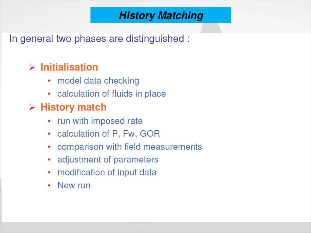
History Matching
Reduce Operation Expenses
Increase Recovery
Prediction
18
19. Problem definition
1920. Data review
2021. Main Types of Data
2122. Study approach
2223. Study approach
2324. GRID TYPES
2425. GRID TYPES
2526. Sugar box geometry
2627. Sugar box geometry
2728. Corner point geometry
2829. Reservoir description : PROPERTIES
2930. Reservoir description : PROPERTIES
3031. Reservoir Discritization
Defination: the reservoir is described by a set of gridblocks (orgridpoints) whose properties, dimensions, boundaries, and locations in the
reservoir are well defined.
Block centered grid
Point distributed grid
i-1
i
i+1
ΔY
ΔX
ΔX
31
32. Block Identification and Ordering
3233. Block Identification and Ordering
• Natural ordering• Zebra ordering
• Diagonal D2 ordering
• Alternating diagonal
D4 ordering
• Cycle ordering
• Cycle-2 ordering
33
34. GRID SIZE SELECTION
3435. ACTIVE and DEAD CELLS
3536. GEOLOGICAL CONSTRAINTS
3637. CHOICE OF VERTICAL DISCRETIZATION
3738. Using LGR to model gas coning
3839. Block-centered grid
3940. Block-centered grid
4041. Block-centered grid
4142. Dip or fault ?
4243. CPG grid intercell flow
4344. Fault description in CPG grid
4445. Example of CPG reservoir model
4546. Fault description in CPG grid
4647. Reservoir layering: Use of log Correlation
K.FEKI47
48. Upscaling
• Optimum level ofand techniques
for upscaling to
minimize errors
Gurpinar, 2001
48
49. Rock properties: Main parameters
4950. Rock properties: Net thickness and porosity
5051. Rock properties: Compressibility
5152. Rock properties: Compressibility
5253. Horizontal & Vertical Permeability
Horizontal & Vertical Permeability53
54. Horizontal Permeability
5455. Vertical Permeability
5556.
History Matching56
57.
History Matching57
58.
History Matching58
59.
FIRST STEP - GENERAL FIELD MATCH - RUN 159
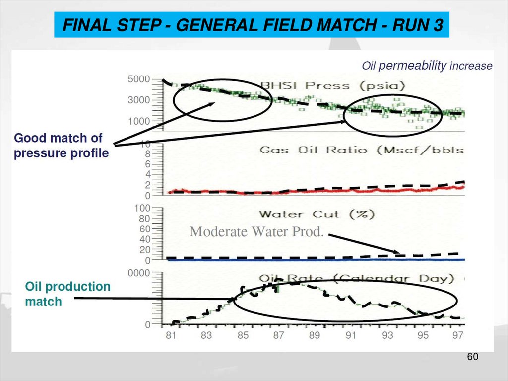
60.
FINAL STEP - GENERAL FIELD MATCH - RUN 360
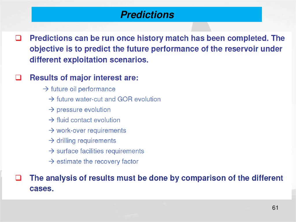
61.
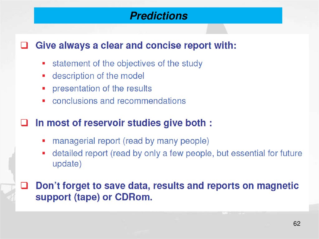
Predictions61
62.
Predictions62
63.
Predictions63
64. Fluid flow equations
Conservation laws
–
Conservation in mass
Assume:
–
–
Isothermal condition
complete and instantaneous phase equilibration in each cell
Conservation in energy
Conservation in momentum
Additional constraints
Wells and facilities
Large number of non-linear equations
64
65. Fluid flow equations
Type of fluid in the reservoir
Flow regimes
Reservoir geometry
Number of flowing fluids in the reservoir
65
66. Type of fluid in the reservoir
IncompressibleSlightly compressible
Compressible
66
67. Flow regimes
Steady State flowUnsteady State flow
Pseudo Steady State flow
67
68. Reservoir geometry
Radial flow
Linear flow
Spherical and Hemispherical flow
68
69. Number of flowing fluids in the reservoir
Single Phase flow
Two phase flow
Three phase flow
69
70. IN OUT
Reservoir SimulatorPressure
Saturation
Newton-Raphson (IMPLICIT)
all primary variables are calculated at the same time.
IMplicit Pressure Explicit Saturation (IMPES)
The IMPES procedure solves for pressure at the new time level using
saturations at the old time level, and then uses the pressures at the
new time level to explicitly calculate saturations at the new time level
70
71. Numerical Models
Black oil modelo
o
Depletion
Water Injection
Component: oil water gas
Phase: Oil water gas
71
72.
Compositional modelo
o
Gas injection to increase or maintain reservoir pressure
Miscible flooding as the injection gas goes into solution with oil
Carbon dioxide flooding, with the gas soluble in both oil and water
Thick reservoirs with a compositional gradient caused by gravity
Reservoirs with fluid compositions near the bubblepoint
High-pressure, high temperature reservoirs
Natural-fracture reservoir modeling.
Component: C1,C2, ….So2,H2S,N2,..
Phase: Oil water gas
72
73.
Chemical modelo
o
Polymer and surfactant injection
Component: Water oil surfactant alcohol
Phase: Agues oleic microemulsion
73
74. Reservoir simulators
ECLIPSEGPRS
SENSOR
NEXUS
UTCHEM
Boast 3
COMET3
…
Objective
Accuracy
Time
Limitations
User friendly
Easy to integrate
…
74
75. Eclipse reservoir simulator
• Commercial reservoir simulator for over 25 years• Black-oil
• Compositional
• Thermal
• Streamline
75
76. Eclipse reservoir simulator
Local Grid RefinementGas Lift Optimization
Gas Field Operations
Gas Calorific Value-Based
Control
Geomechanics
Coalbed Methane
Networks
Reservoir Coupling
Flux Boundary
Environmental Traces
Open-ECLIPSE Developer's Kit
Pseudo-Compositional
EOR Foam
EOR Polymer
EOR Solvent
EOR Surfactant
Wellbore Friction
Multisegmented Wells
Unencoded Gradients
Parallel ECLIPSE
76
77. Grid definition : Example
7778. Rock properties: Main parameters
7879. Thank You!
7980. Quiz
• Look at the following sentences . Establishfor each one if it is a true or false
1.
2.
3.
4.
5.
6.
7.
8.
9.
10.
Reservoir layering should be defined before XY grid
Reservoir layering is derived from well data
Reservoir layering is derived from fault geometry
Reservoir layering should respect wells correlation
Reservoir layering should respect flow unit
Grid geometry can vary with time
Any grid has locally three main flow directions
Grid axes should be locally orthoganal
One cell can communicate with maximum of 6 neighbours
grid blocks are refered by three indexes (I ,j , k)
K.FEKI
80