


 Строительство
Похожие презентации:


Специальный военный вестник "Армия Защитников Отечества" №15
1.
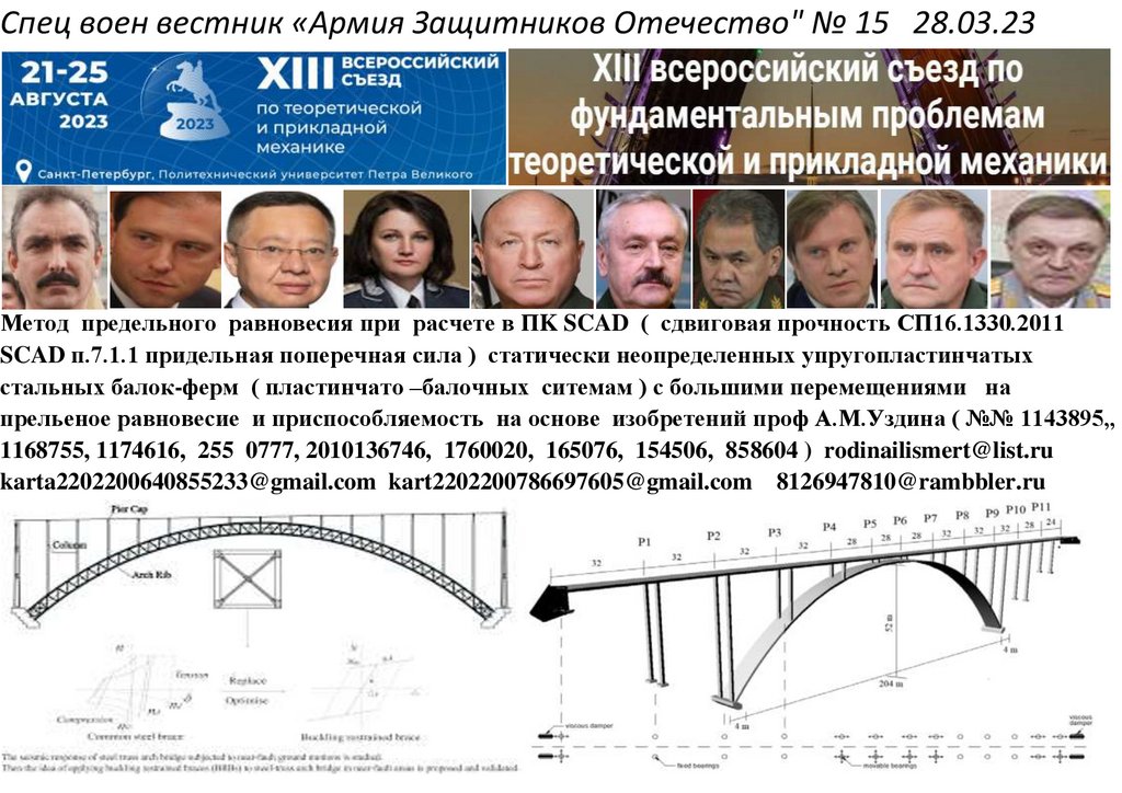
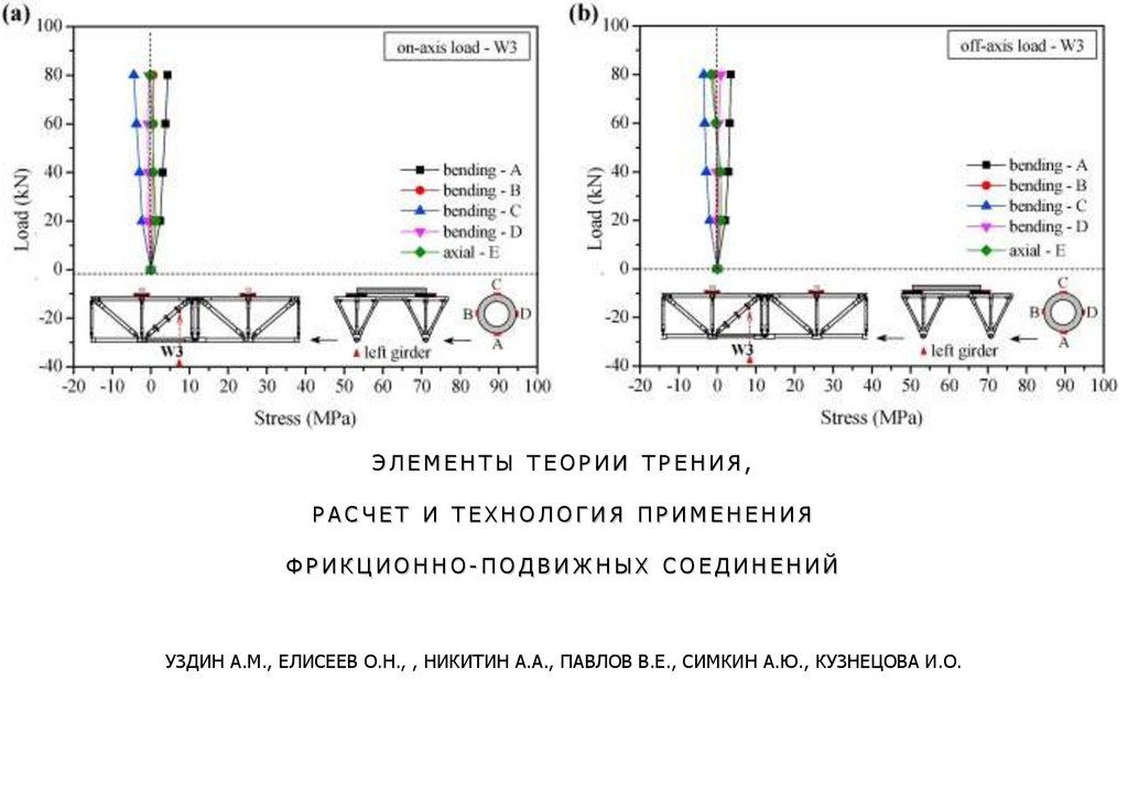
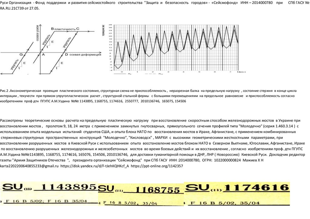
Спец воен вестник «Армия Защитников Отечество" № 15 28.03.23Метод предельного равновесия при расчете в ПK SCAD ( сдвиговая прочность СП16.1330.2011
SCAD п.7.1.1 придельная поперечная сила ) статически неопределенных упругопластинчатых
стальных балок-ферм ( пластинчато –балочных ситемам ) с большими перемещениями на
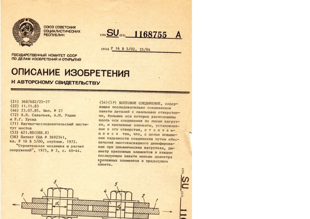
прельеное равновесие и приспособляемость на основе изобретений проф А.М.Уздина ( №№ 1143895,,
1168755, 1174616, 255 0777, 2010136746, 1760020, 165076, 154506, 858604 ) [email protected]
[email protected] [email protected] [email protected]
2.
Для включения в план НИОКР Минстроя ЖКХ, Минпромторга, МинтрасаДистанционный доклад (сообщение) на НТС Минстроя ЖКХ на удаленке из поселения ученого, заместителя,
заместителя Президента организации "Сейсмофонд" при СПб ГАСУ, редатора газеты "Армия Защмиников
Отечества", полковника Шендакова Михаил Анатольевича на научно -техническом ( Совете НТС в Минстрое ЖКХ в
марте -апреля 2023 и доклад на научной конференции в Политехническом Университете СПб 21 - 25 августа 2023
года
Тема доклада: Метод предельного равновесия при расчете в ПK SCAD ( сдвиговая прочность
СП16.1330.2011 SCAD п.7.1.1 придельная поперечная сила ) статически неопределенных
упругопластинчатых стальных ферм-балок ( пластинчато –балочных ситемам ) с большими
перемещениями на прельеное равновесие и приспособляемость на основе изобретений проф
А.М.Уздина ( №№ 1143895,, 1168755, 1174616, 255 0777, 2010136746, 1760020, 165076, 154506, 858604 )
и инженерные решения по использованию для железнодорожных мостов упругопластических сверхлегких и
сверхпрочных конструкций стальных ферм-балок, сконструированном со встроенным бетонным настилом, с
пластическим шарниром и расчет в 3D-модели, в SCAD неразрезной балки-фермы с большими
перемещениями, с учетом сдвиговой жесткостью к неравномерным нагрузкам железнодорожного
моста, для преодоления водных преград в критических и чрезвычайных ситуациях, позволяющих
уменьшить массу пролетного строения армейского моста до 30 процентов, за счет пластинчатости и
приспособляемости моста, что уменьшит сметную стоимость СМР до 30 процентов
Секция III. Механика деформируемого твердого тела - 2. Теория пластичности и ползучести Съезд 21-25
августа 2023 Политехнический Университет Петера Великого Доклад СПб ГАСУ XIII Всероссийский съезд по
фундаментальным проблемам теоретической и прикладной механики, Санкт-Петербург, 21-25 августа 2023 года
тед./факс: (812) 694-78-10 [email protected] [email protected] [email protected]
3.
Уворованная ТЕОРИИ ТРЕНИЯ, РАСЧЕТЫ И ТЕХНОЛОГИЯ ФПС, патентыЛИИЖТа , изобретенные в СССР проф. дтн ПГУПС А.М.Уздиным и внедренная чужими в
США, КНР: паразитами- глобалистами сатанистами США, КНР - разворованная Страна
СССР СОЕДИНЕНИЙ на сдвих Application of BRB to Seismic Mitigation of Steel
Truss Arch Bridge Subjected to Near-Fault Ground Motions
Теория и практика применения пластической деформаций и удерживания изгиба
пролетного строения моста, при напряженно деформируемом стоянии
автомобильного моста с использованием опыта китайских и американских
инженеров для восстановления разрушенных мостов во время специальной
военной опрераци в Одесской области ( 8 баллов сейсмичность ) и на Украине.
Тема 2. Применение BRB для смягчения сейсмических воздействий на арочных
мостах из стальных ферм, подверженный колебаниям грунта вблизи разлома в
г.Одесса. (Украина) [email protected] [email protected]
Application of BRB to Seismic Mitigation of Steel Truss Arch Bridge Subjected to
Near-Fault Ground Motions [email protected]
Сейсмическое проектирование мостов против движений грунта вблизи
разломов с использованием комбинированных систем сейсмоизоляции и
ограничения LRBs и CDRs
4.
Seismic Design of Bridges against Near-Fault Ground Motions Using CombinedSeismic Isolation and Restraining Systems of LRBs and CDRs
Оценка динамического отклика длиннопролетных армированных арочных
мостов, подверженных колебаниям грунта в ближнем и дальнем поле
Dynamic Response Evaluation of Long-Span Reinforced Arch Bridges Subjected
to Near- and Far-Field Ground Motions
Запрос редакции газеты "Армия Защитников Отечества" о дистанционно или выездном в СИЗО или психзоведнния
где незаконно содержится заместитель редактора газеты "Армия Защитников Отечества " основной докладчик
Шендаков Михаил Анатольевич Приложение доклада для дистанционного сообщения содержание тезисов
открытого доклада для включения в план НИОКР на 2023 и принятия решения на научно техническом совет (НТС)
Минстроя ЖКХ, Минпромторга , Минтраса и для Секции III. Механика деформируемого твердого тела - 2. Теория
пластичности и ползучести 21-25 августа 2023 Политехнический Университет Петера Великого Дистанционный
доклад (сообщение) на удаленки из поселения ученого , заместителя Президента организации "Сейсмофонд" при
СПб ГАСУ, полковника Шендакова Михаил Анатольевича на научно -техническом (НТС) Совете в марте -апреля 2023
и доклад на научной конференции в Политехническом Университете 23 - 25 августа 2023 гола ю Тема доклада:
Новые инженерные решения использование для железнодорожных мостов упругопластических сверхлегких и
сверхпрочных конструкций стальных ферм-балок, сконструированном со встроенным бетонным настилом, с
пластическим шарниром и расчет в 3D-модели, в SCAD неразрезной балки-фермы с большими
перемещениями, с учетом сдвиговой жесткостью к неравномерным нагрузкам железнодорожного
моста, для преодоления водных преград в критических и чрезвычайных ситуациях, позволяющих
уменьшить массу пролетного строения армейского моста до 30 процентов, за счет пластинчатости и
приспособляемости моста, что уменьшит сметную стоимость СМР до 30 процентов
5.
УДК 69.05:Метод предельного равновесия при расчете в ПK SCAD ( сдвиговая прочность СП16.1330.2011
SCAD п.7.1.1 придельная поперечная сила ) статически неопределенных упругопластинчатых
стальных ферм-балок ( пластинчато –балочных ситемам ) с большими перемещениями на
прельеное равновесие и приспособляемость на основе изобретений проф А.М.Уздина ( №№ 1143895,,
1168755, 1174616, 255 0777, 2010136746, 1760020, 165076, 154506, 858604 ) [email protected]
[email protected] [email protected] [email protected]
XIII Всероссийский съезд по фундаментальным проблемам теоретической и прикладной механики, Санкт-Петербург, 21-25 августа 2023 года тед./факс: (812) 694-78-10
[email protected] [email protected] [email protected]
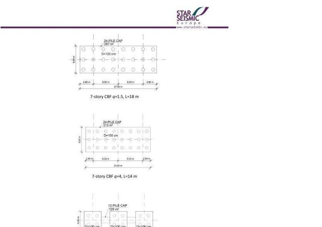
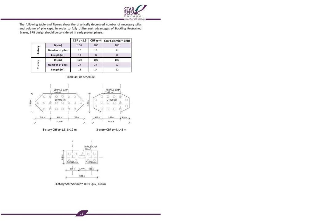
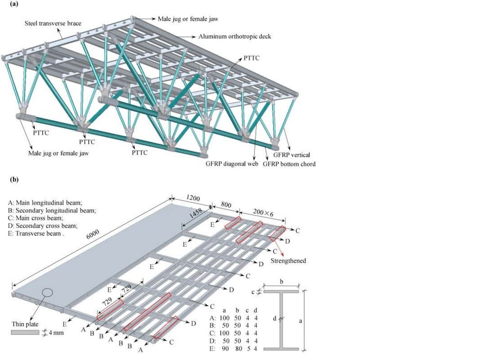
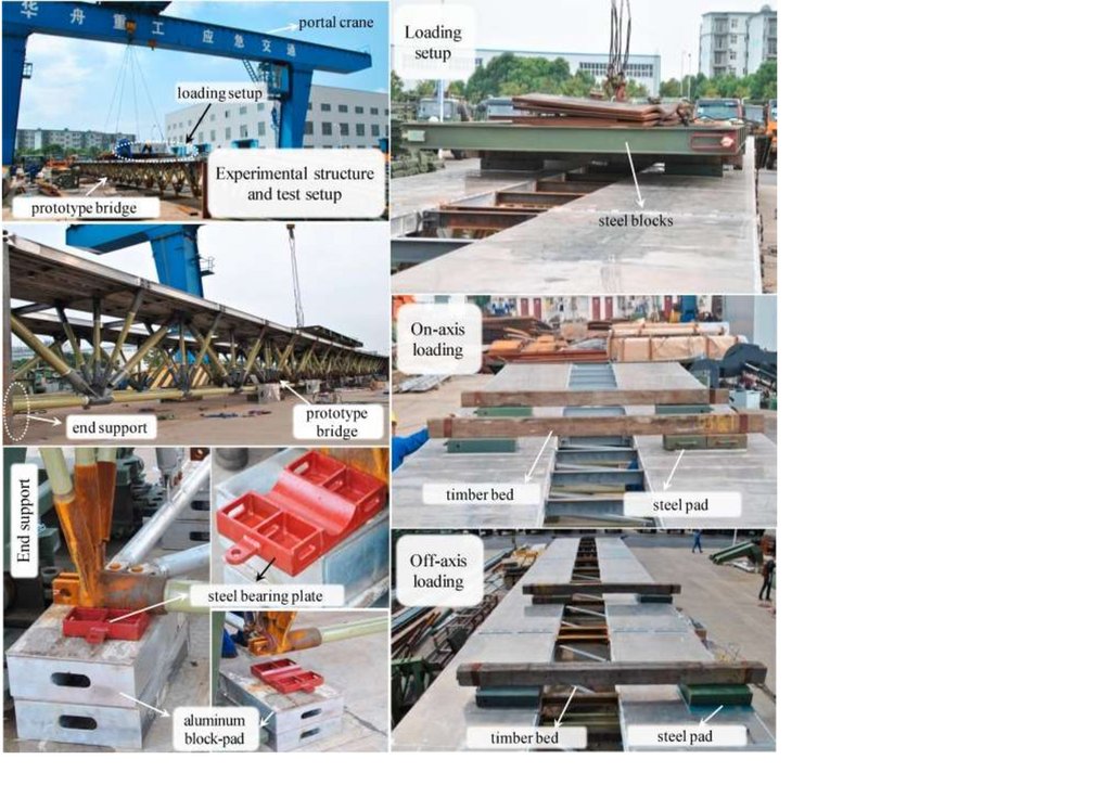
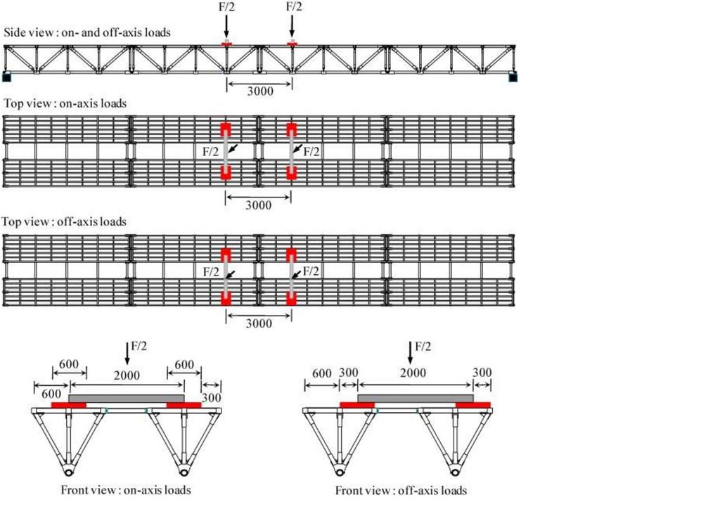
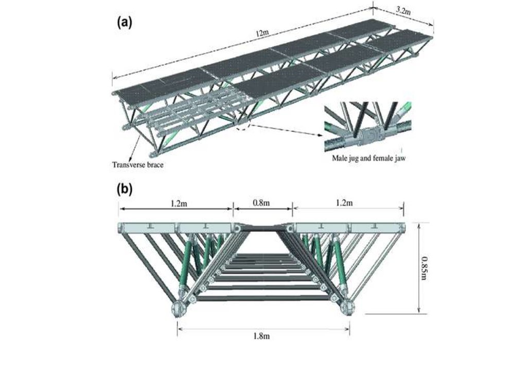
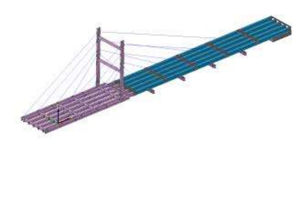
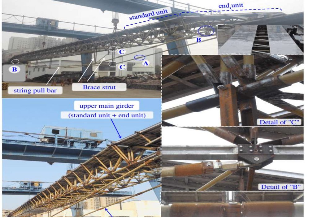
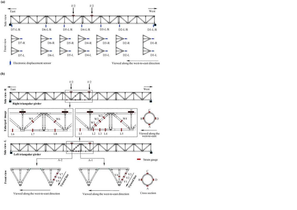
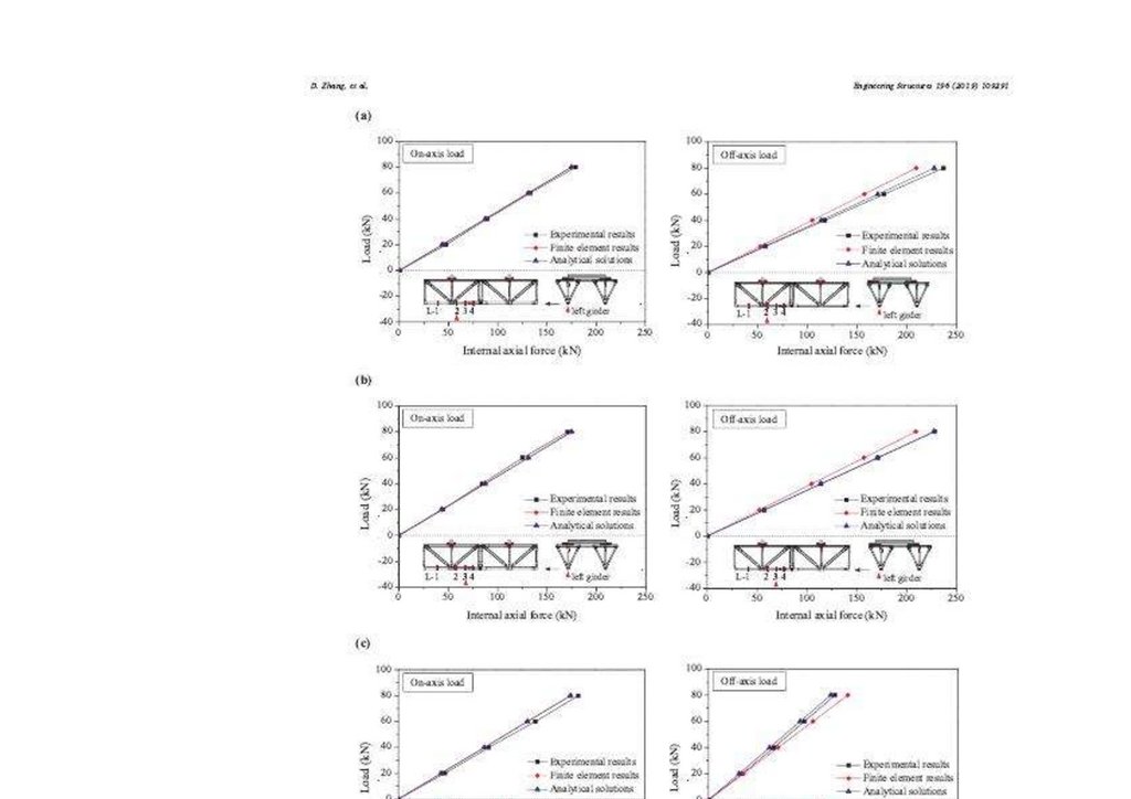
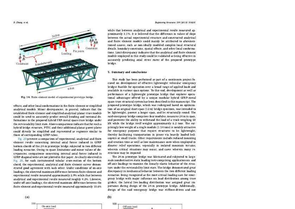
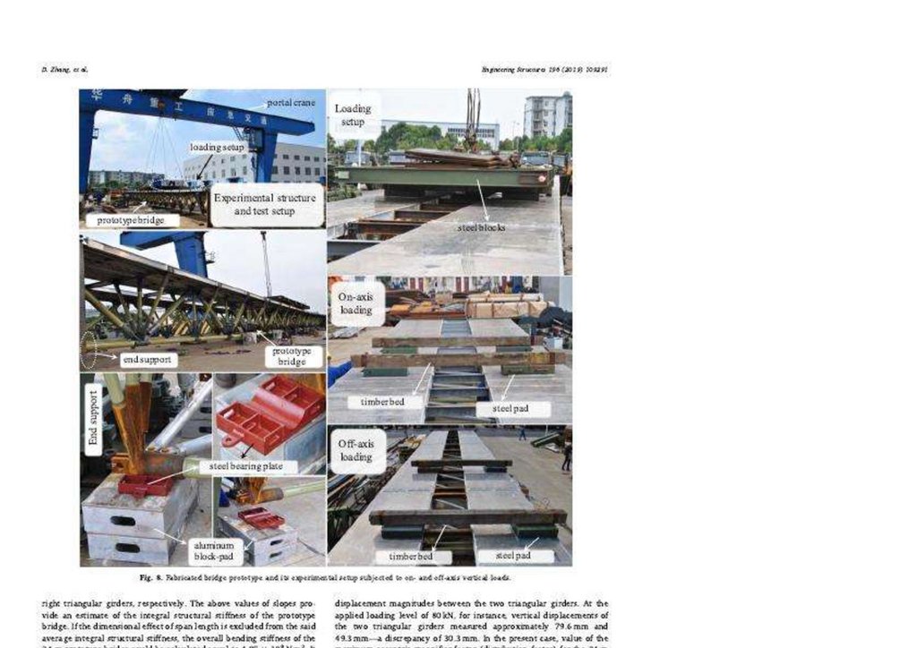
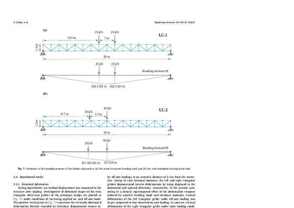
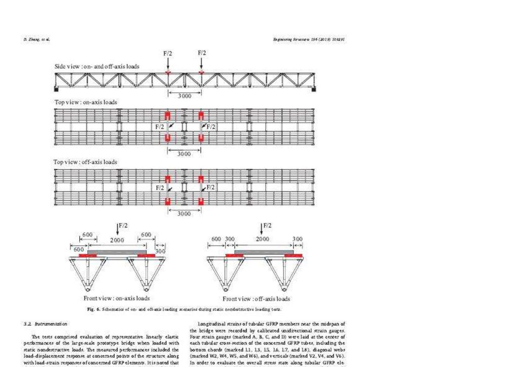
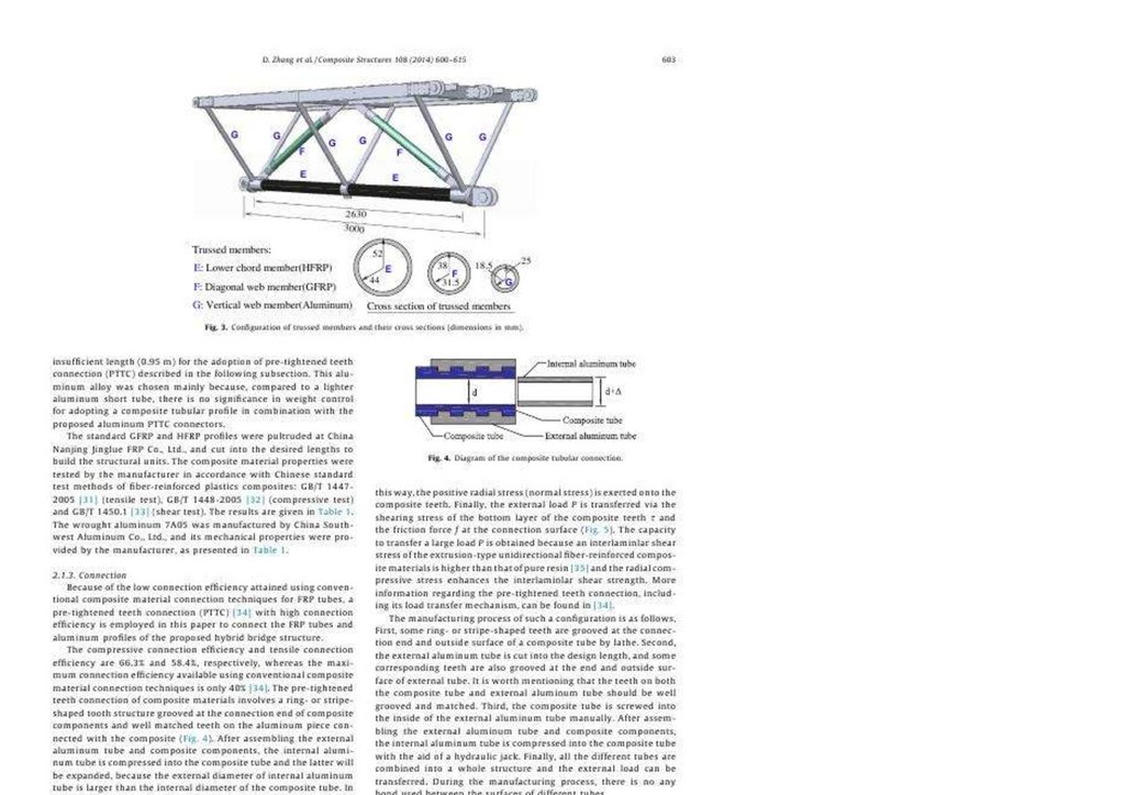
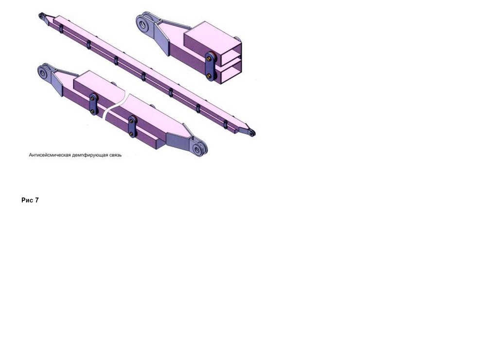
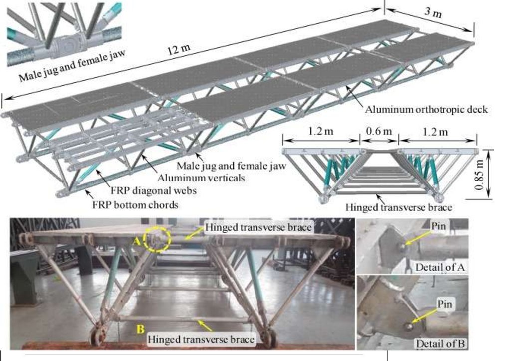
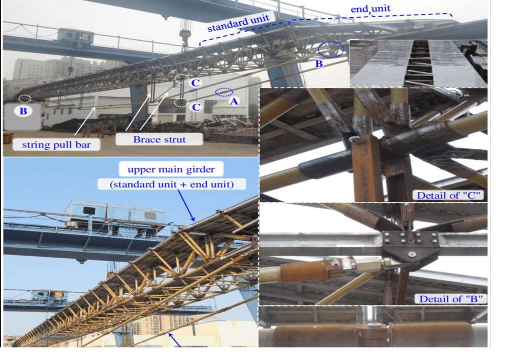
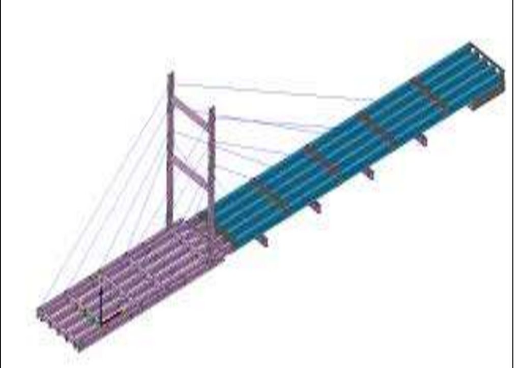
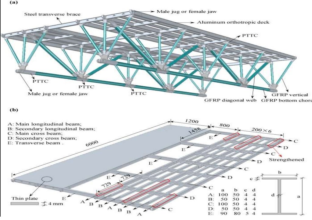
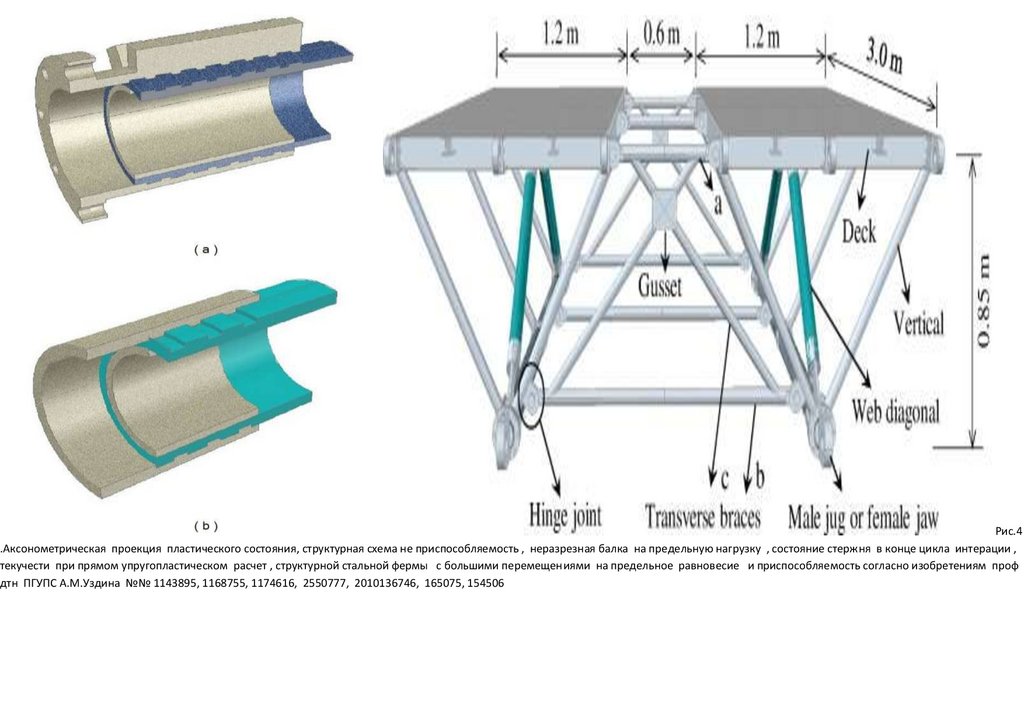
Development of lightweight emergency bridge using GFRP -metal composite plate-truss girder
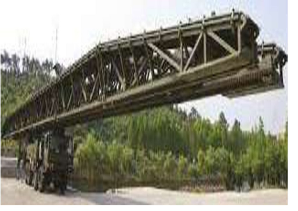
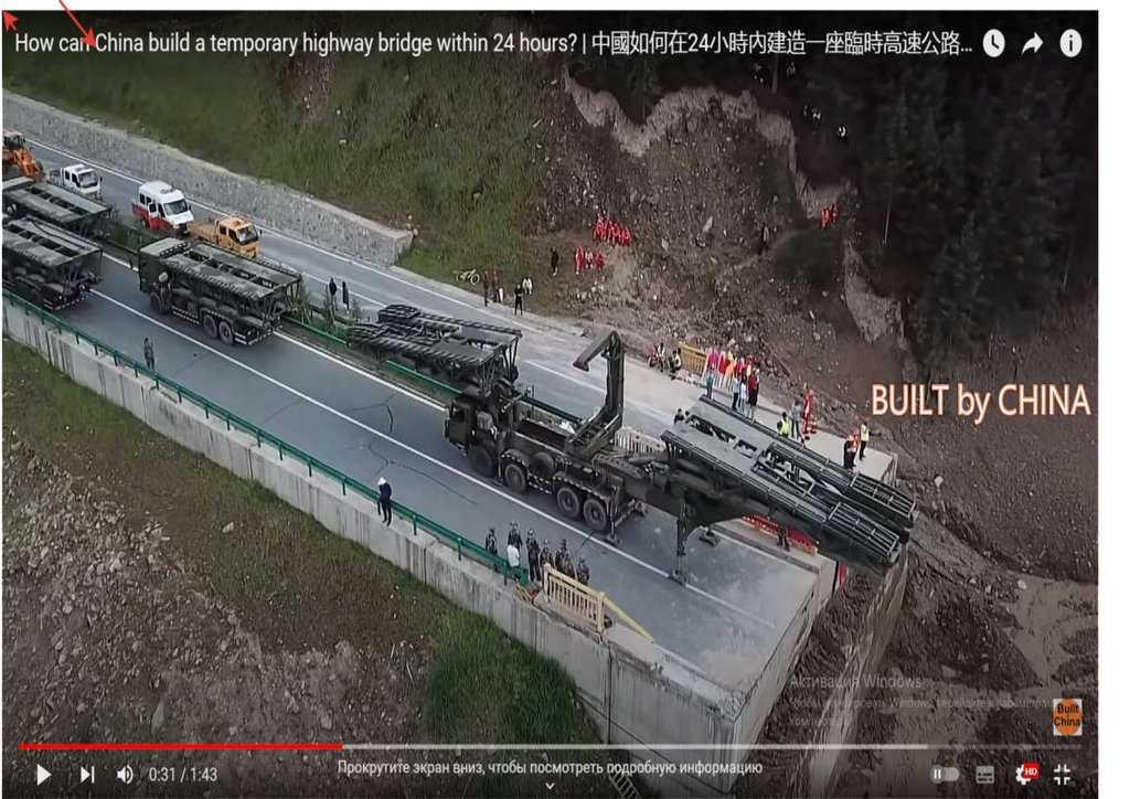
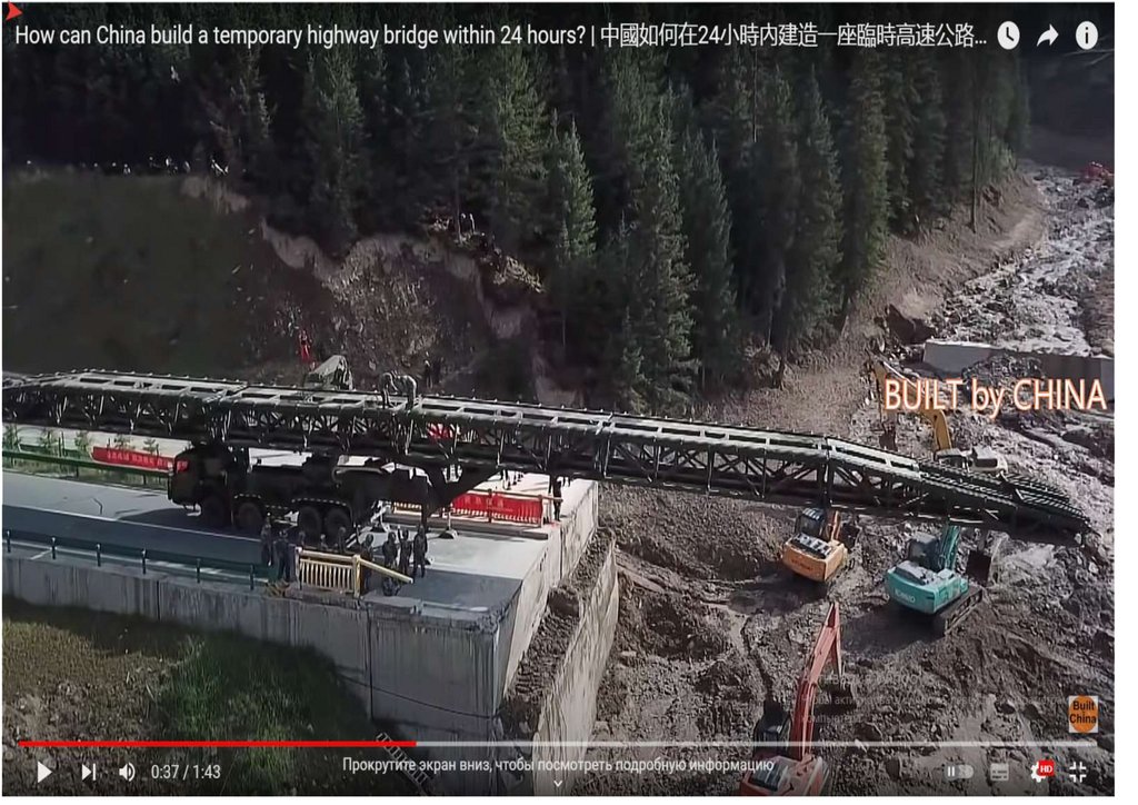
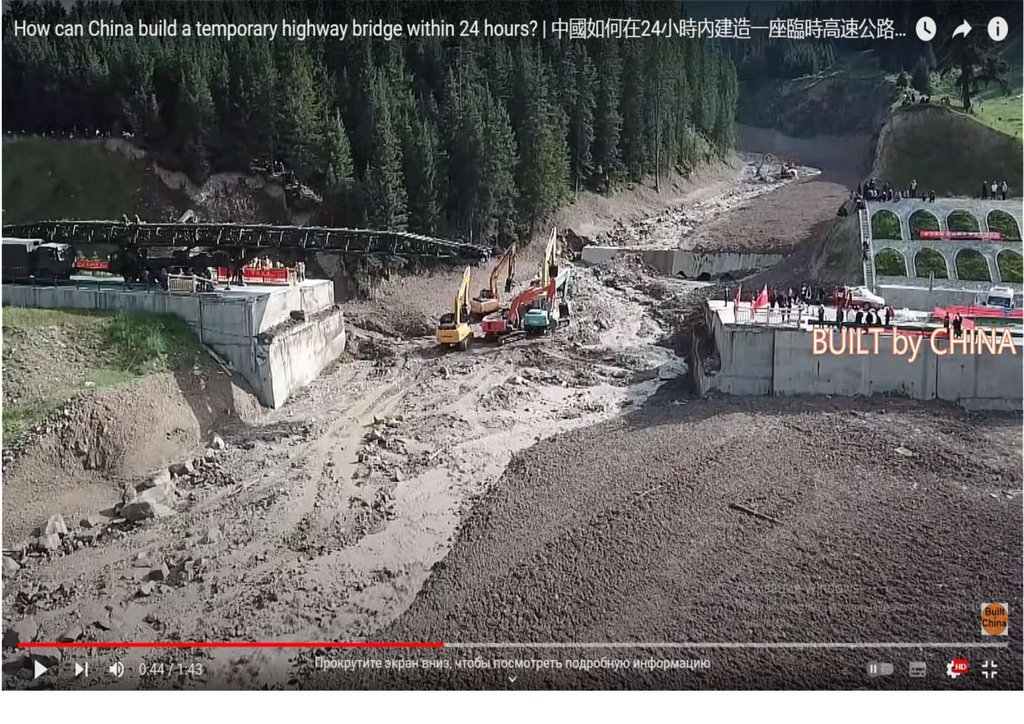
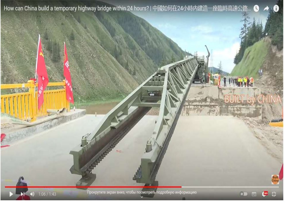
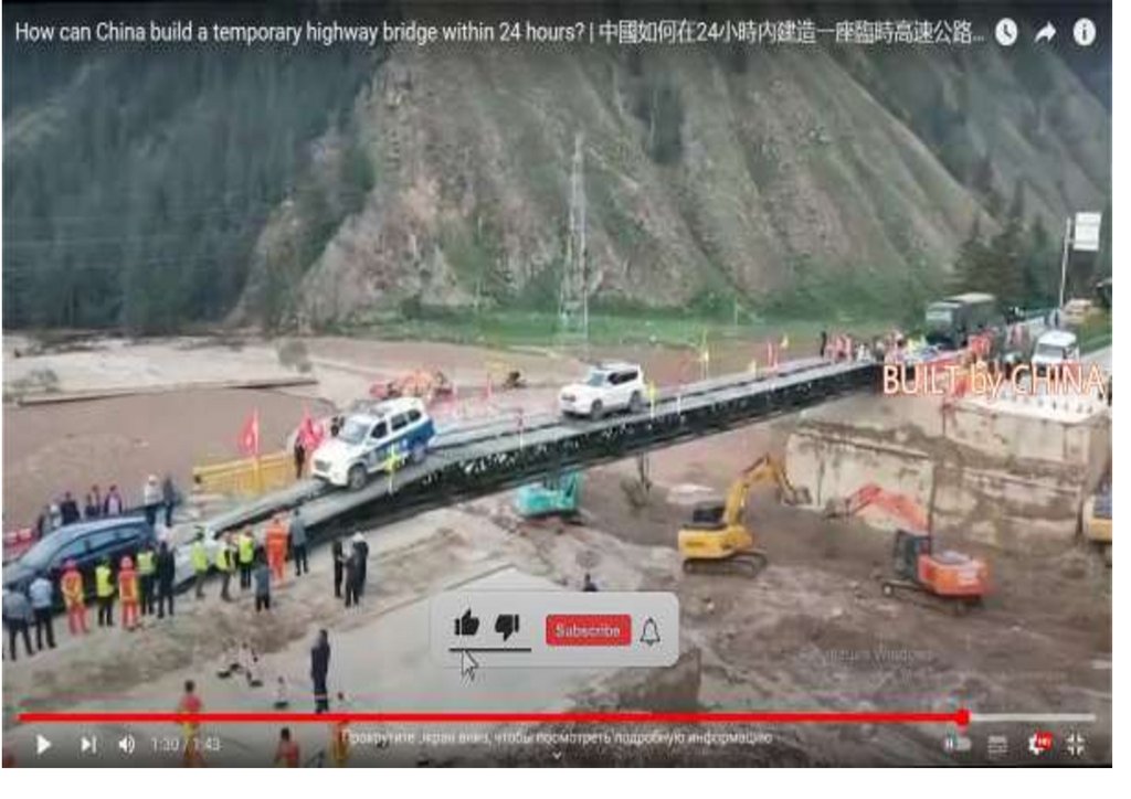
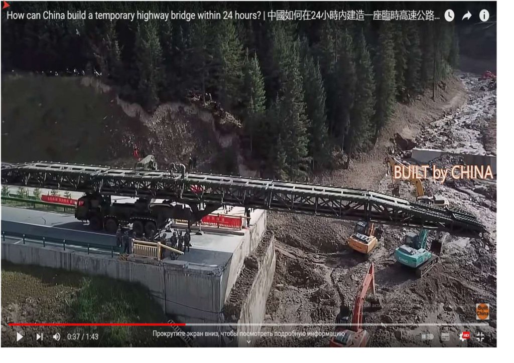
Редакция газеты «Армия Защитников Отечества» при СПб ГАСУ сообщает о разработанной в КНР , США
конструкции легкого аварийного автомобильного моста, состоящего из стеклопластиковой металлической
композитной плиты–ферменной балки и имеющего пролет 24 м. Указанный мост был спроектирован на
основе оптимизации оригинального 12-метрового образца моста построенного в КНР, США в 2019 г.
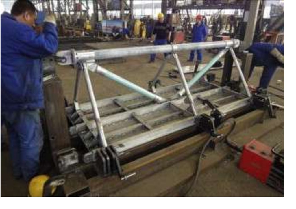
Разработанный таким образом мост очень легкий, конструктивно прочным, с возможностью модульной
реализации и представлять собой конструкцию, которая требует меньше времени при сборке моста в
полевых условиях . Дирекцией информационного агентство «Русской Народной Дружной» выполнен
6.
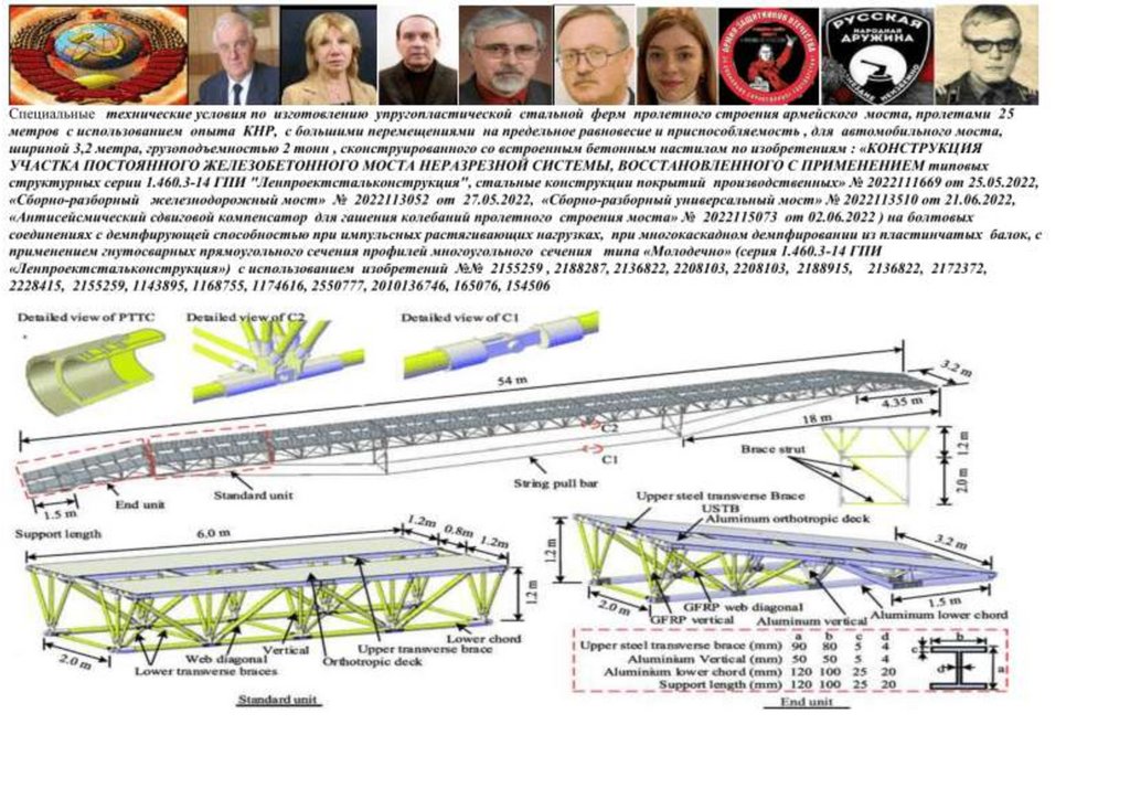
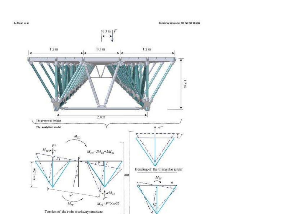
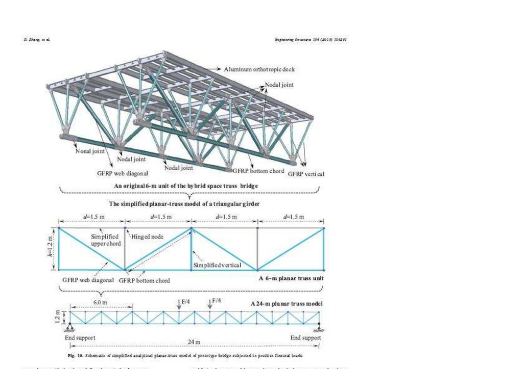
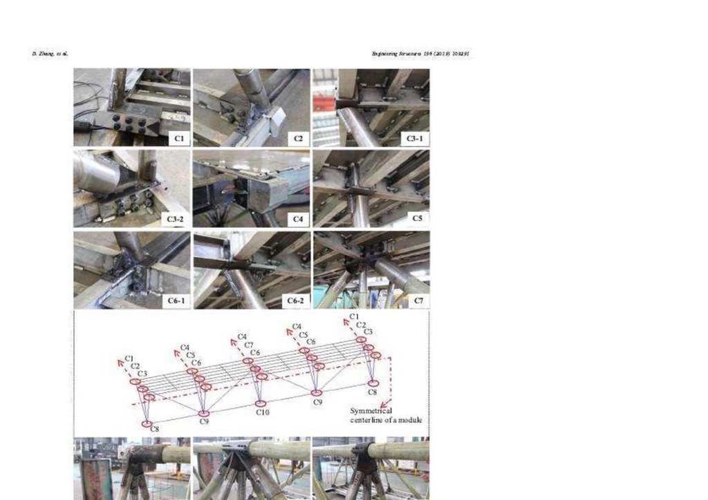
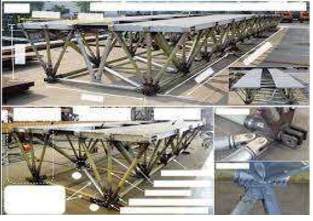
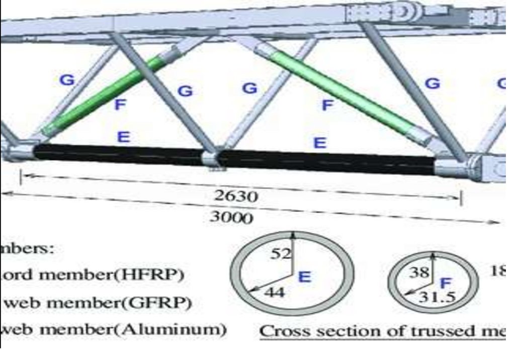
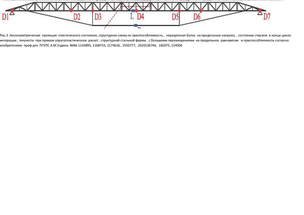
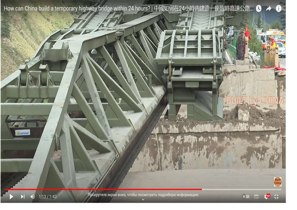
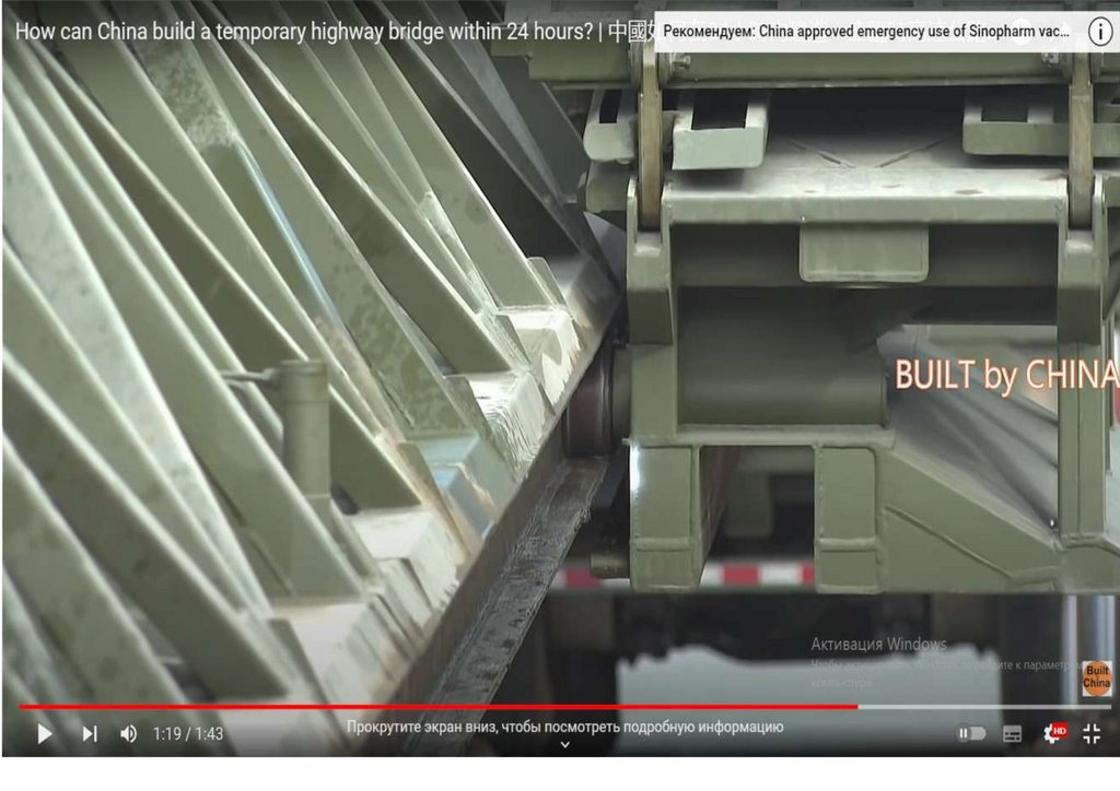
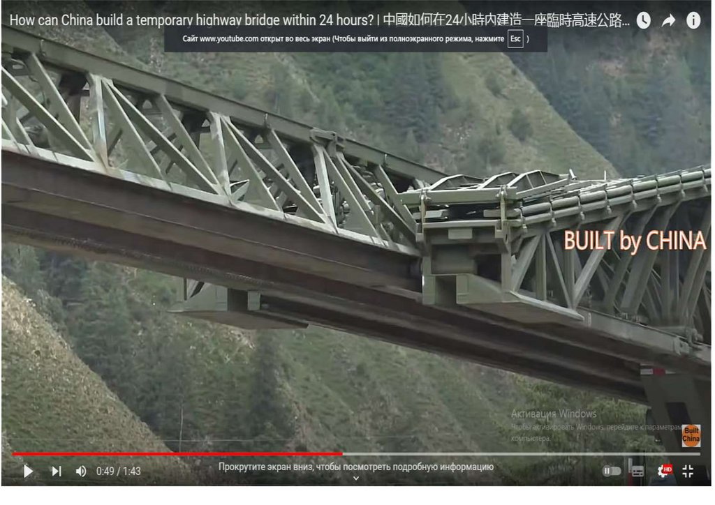
РАСЧЕТ УПРУГОППЛАСТИЧЕСКОГО СТРУКТУРНОГО СБОРОНО РАЗБОРОНОГО МОСТА НА ОСНОВЕТРЕХГРАННОЙ БЛОК-ФЕРМЫ на напряженно деформируемое состояние (НДС) структурных стальных ферм
с большими перемещениями на предельное равновесие и приспособляемость , по чертежам китайским и
американских инженеров , уже построенных из упругопластических стальных ферм выполненных из
сверхлегких, сверхпрочных полимерных гибридных материалов GFRP-MЕТАЛЛ, с использование
стекловолокон, для армейского быстро собираемого моста, для чрезвычайных ситуациях , длинною 24
метра , грузоподъемностью 5 тонн из трубчатых GFRP-элементов в КНР [email protected]
[email protected] [email protected] [email protected] [email protected]
[email protected]
USA Zayavlenie gazeti Armiya Zachitnikov Otechestva rassmotrenie NTS NIOKR primenenie uprugoplasticheskix balok-ferm mostov doklad Shendakovf 717 str
https://disk.yandex.ru/d/4_3-6-wS1TJGEA
USA Zayavlenie gazeti Armiya Zachitnikov Otechestva rassmotrenie NTS NIOKR
primenenie uprugoplasticheskix balok-ferm mostov doklad Shendakovf 717 str
https://studylib.ru/doc/6396766/usa-zayavlenie-gazeti-armiya-zachitnikov-otechestva-rassm...
https://mega.nz/file/XYAX2ChQ#ZsKyPj-FOARrK7wSo8DC9-87VFfMGQ7HL20EHlikl6Q
https://ibb.co/5WJybFk
https://vk.com/wall789869204_102
LIIJT Zayavlenie gazeti Armiya Zachitnikov Otechestva rassmotrenie NTS NIOKR primenenie
uprugoplasticheskix balok-ferm Shendakovf 415 str
https://ppt-online.org/1323128 https://ppt-online.org/1323128
7.
Ваше обращение в адрес Правительства Российской Федерации поступило на почтовый сервер ибудет рассмотрено отделом по работе с обращениями граждан. Номер Вашего обращения 2095962.
Закрыть
Уважаемый председатель Правительства Мишустин Михаил Владимирович Редакция газеты
Армия Защитников Отечества просит обязать Минстрой ЖКХ Минторг Минтрас рассмотреть на
научно-техническим совете НТС для включения в план НИОКР на 2023 изобретения ученого
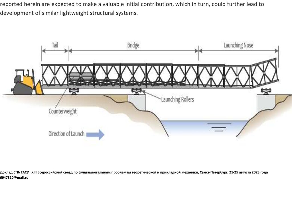
Шендакова Михаила Анатольевича по использованию при чрезвычайных ситуациях сборноразборный мост из стальных упругопластических ферм-балок при преодолению водных преград
через реку Днепр в смоленской области и помочь включить в план НИОКР на 2023 сумму
необходимо запланировать в объеме 1500 тыс рублей Срок изготовления опытного образа
переправы пролетом 30 метро 6 месяцев Время сборки мост 24 часа в полевых условия со
встроенным бетонным настилом Грузоподъемность армейского быстро- собираемого моста 5
тонн Служу России Полковник Михаил Шендаков и Мжиев Хасвн Нажоевич
Большое спасибо!
Отправленное 28.03.2023 Вами письмо в электронной форме за номером ID=9956873 будет
доставлено и с момента поступления в Администрацию Президента Российской Федерации
зарегистрировано в течение трех дней.
Президенту Российской Федерации
Фамилия, имя, отчество: Мажиев Хасан Нажоевич
8.
Организация: Организация "Сейсмофонд" при СПб ГАСУ ОГРН 1022000000824 ИНН2014000780
Адрес электронной почты: [email protected]
Телефон: 9111758465
Тип: обращение
Текст
Редакция газеты Армия защитников Отечества просить обязать Минстрой ЖКХ рассмотреть
тезисы доклада и включить в план НИОКР и рассмотреть НТС проектирование испытание
сборно разборных армейских мостов Прилагается заявление на 3 стр
Отправлено: 28 марта 2023 года, 15:49
Расчет упругопластического структурного сборно-разборного моста на основе
трехгранной блок-фермы https://ppt-online.org/1297775
9.
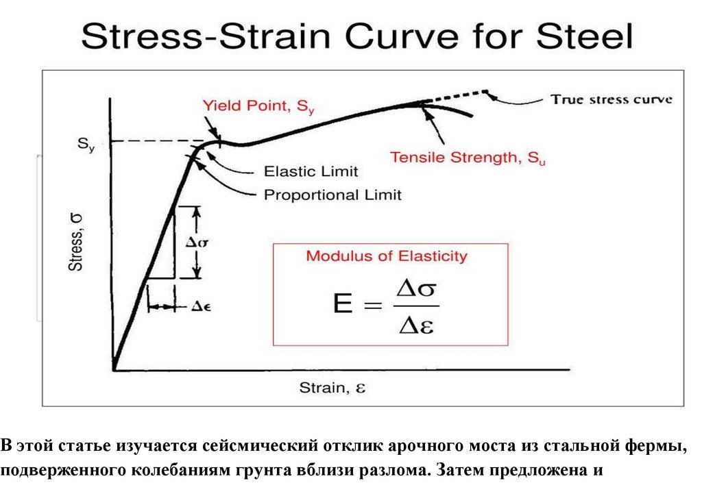
В этой статье изучается сейсмический отклик арочного моста из стальной фермы,подверженного колебаниям грунта вблизи разлома. Затем предложена и
10.
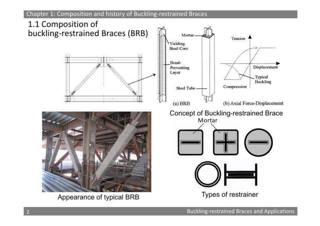
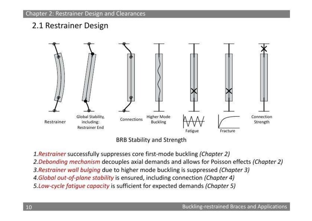
подтверждена идея применения удерживающих изгиб скоб (BRBs) к арочномумосту со стальной фермой в зонах вблизи разломов. Во-первых, идентифицируются
и различаются основные характеристики движений грунта вблизи разломов.
Кроме того, сейсмический отклик большого пролета для Одесской области (
Украина )
Секция III. Механика деформируемого твердого тела - 2. Теория пластичности и
ползучести 21-25 августа 2023 Политехнический Университет Петера Великого Доклад СПб
ГАСУ XIII Всероссийский съезд по фундаментальным проблемам теоретической и прикладной
механики, Санкт-Петербург, 21-25 августа 2023 года тед./факс: (812) 694-78-10
[email protected] [email protected] [email protected]
Development of lightweight emergency bridge using GFRP -metal composite platetruss girder
Редакция газеты «Армия Защитников Отечества» при СПб ГАСУ сообщает о
разработанной в КНР , США конструкции легкого аварийного автомобильного
моста, состоящего из стеклопластиковой металлической композитной плиты–
ферменной балки и имеющего пролет 24 м. Указанный мост был спроектирован
на основе оптимизации оригинального 12-метрового образца моста
построенного в КНР, США в 2019 г. Разработанный таким образом мост очень
11.
легкий, конструктивно прочным, с возможностью модульной реализации ипредставлять собой конструкцию, которая требует меньше времени при сборке
моста в полевых условиях . Дирекцией информационного агентство «Русской
Народной Дружной» выполнен РАСЧЕТ УПРУГОППЛАСТИЧЕСКОГО
СТРУКТУРНОГО СБОРОНО РАЗБОРОНОГО МОСТА НА ОСНОВЕ ТРЕХГРАННОЙ
БЛОК-ФЕРМЫ на напряженно деформируемое состояние (НДС) структурных
стальных ферм с большими перемещениями на предельное равновесие и
приспособляемость , по чертежам китайским и американских инженеров , уже
построенных из упругопластических стальных ферм выполненных из
сверхлегких, сверхпрочных полимерных гибридных материалов GFRP-MЕТАЛЛ,
с использование стекловолокон, для армейского быстро собираемого моста,
для чрезвычайных ситуациях , длинною 24 метра , грузоподъемностью 5 тонн из
трубчатых GFRP-элементов в КНР [email protected]
[email protected] [email protected] [email protected]
[email protected] [email protected] (911) 175-84-65
12.
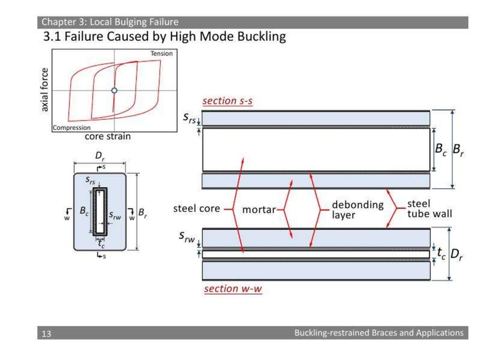
13.
14.
15.
16.
Заявление(применение) BRB к Сейсмическому Уменьшению СтальногоМоста Арки(дуги) Связки, подвергнутого Почти Движениям
Основания(земли) Ошибки
1
2
Haoyuan Gao
< Https: // orcid. org/0000-0002-0224-0230 >,
Kun Zhang
< Https: // orcid. org/0000-0003-2897-976X >,
17.
Xinyu Wu3,
Hongjiang Liu
4, * и
Lianzhen Zhang
5
1
Колледж Гражданского строительства, Tongji Университет, Шанхай 200092, Китай
2
Колледж Разработки, Университет Auckland, Auckland 1023, Новая Зеландия
3
Shenyang Geotechnical Исследование и Рассматривающий Компанию Научно-исследовательского института, Ltd., Shenyang 110004, Китай
4
Колледж Гражданских, Окружающей среды и Земля Magement Разработка, Политехнический Университет Mилана, 20133 Mилана, Италия
5
Колледж Науки Транспортирования и Разработки, Harbin Институт Технологии, Harbin 150096, Китай
*
Автор к тому, кого корреспонденция(соответствие) должна быть адресована.
Здания 2022, 12 (12), 2147; < https: // doi. org/10. 3390/buildings12122147 >
18.
Полученный: 16 октября 2022 / Пересмотренный: 23 ноября 2022 / Принятый: 1 декабря 2022 / Изданный: 6 декабря 2022( Эта статья(изделие) принадлежит Специальной Проблеме(выпуску) Новые Тенденции в Сейсмической Оценке Выполнения(работы) < https: //
www.mdpi.com/journal/buildings/special_ issues/J15YK44T64 >)
Разгрузка
Рассматривайте Числа(фигуры) < https: // www. mdpi. com/2075-5309/12/12/2147 >
Примечания Версий < https: // www. mdpi. com/2075-5309/12/12/2147/notes >
Резюме
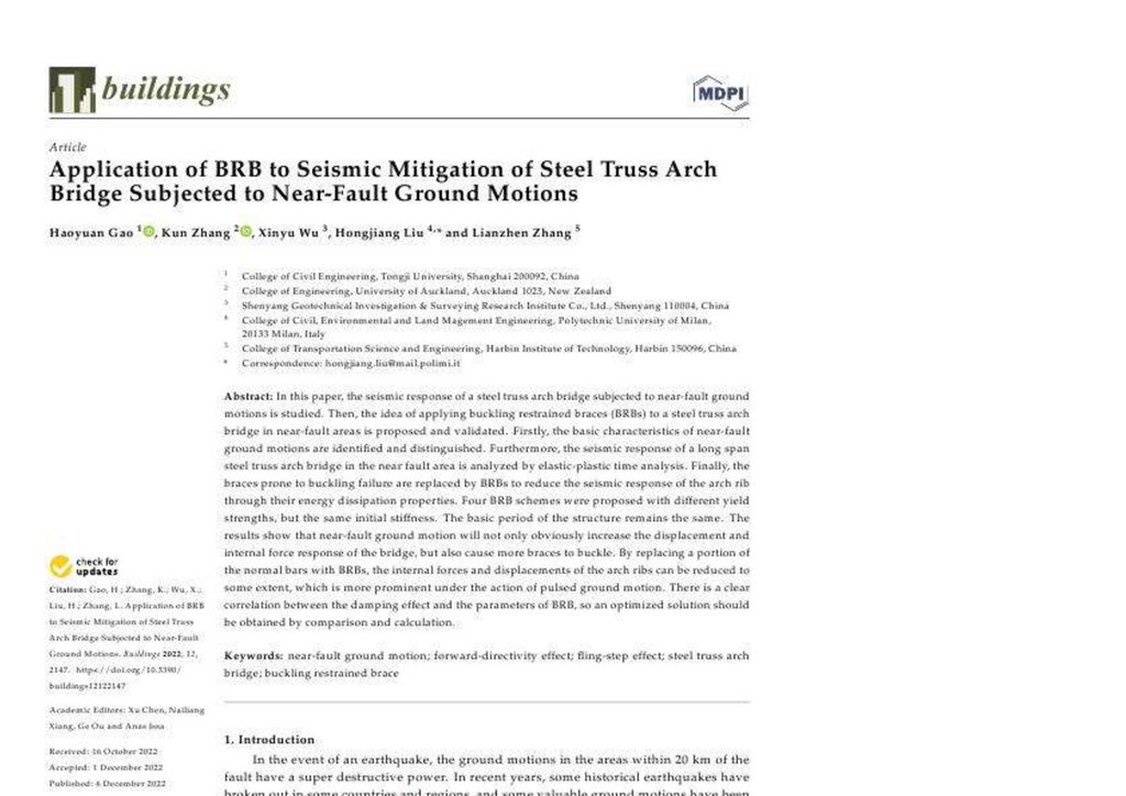
В этой бумаге, сейсмический ответ стального моста арки(дуги) связки, подвергнутого почти движениям основания(земли) ошибки изучается. Тогда, идея
относительно применения(обращения) buckling ограниченные фигурные скобки (BRBS) к стальному мосту арки(дуги) связки в почти областях ошибки
предложена и утверждена. Во-первых, основные характеристики почти движений основания(земли) ошибки идентифицированы и различаются. Кроме того,
сейсмический ответ длинного моста арки(дуги) связки стали промежутка в около области ошибки проанализирован анализом упруги - пластмассовое время.
Наконец, фигурные скобки, склонные к buckling отказу(неудаче) заменены BRBS, чтобы уменьшить сейсмический ответ ребра арки(дуги) через их свойства
разложения энергии. Четыре BRB схемы были предложены с различными силами урожая, но той же самой начальной неподвижностью. Основной период
структуры остается тем же самый. Результаты показывают, что почти движение основания(земли) ошибки очевидно не будет только увеличивать смещение и
внутренний ответ силы моста, но также и причинять большее количество фигурных скобок к застежке. Заменяя часть нормальных брусков(баров) с BRBS,
внутренние силы и смещения ребер арки(дуги) могут быть уменьшены до некоторой степени, который является более видным при действии движения
основания(земли) pulsed. Имеется ясная корреляция между результатом(влиянием) демпфирования и параметрами BRB, так что оптимизированное решение
должно быть получено по сравнению и вычислению.
Keywords:
Почти ошибка основывает движение < https: // www.mdpi.com/search? Q = почти ошибка + основывает + движение >; вперед - directivity производят < https: //
www.mdpi.com/search? Q = вперед - directivity + производят >; результат(влияние) бросать - шага < https: // www.mdpi.com/search? Q = брос& - шаг + производит >;
стальная арка(дуга) связки соединяет < https: // www.mdpi.com/search? Q = сталь + связка + арка(дуга) + соединяет >; buckling ограниченная фигурная скобка <
https: // www.mdpi.com/search? Q = buckling + ограниченный + фигурная скобка >
< Https: // www. mdpi. com/2075-5309/12/12/2147 >
Графическое Резюме
1. Представление
В случае землетрясения, движения основания(земли) в областях в пределах 20 км ошибки имеют разрушительную власть(мощь) высшего качества. В недавних
годах, некоторые исторические землетрясения вспыхнули в некоторых странах и областях(регионах), и некоторые ценные движения основания(земли) были
зарегистрированы. Эти сейсмические данные [< https: // www. mdpi. com/2075-5309/12/12/2147 >] обеспечивают условия(состояния) для структурных инженеров,
чтобы выполнить сейсмическое исследование.
Seismologists и инженеры анализировали характеристики около движений основания(земли) ошибки некоторыми способами. Somerville и другие [< Https: // www.
mdpi. com/2075-5309/12/12/2147 >] указали, что результаты(влияния) пульса в почти областях ошибки причиняют пространственные изменения(разновидности) в
амплитуде движения основания(земли) и продолжительности. Их характеристики и механизм были разработаны многими занятиями(изучениями) (Wu и другие [<
Https: // www. mdpi. com/2075-5309/12/12/2147 >], Yang и Zhou [< https: // www. mdpi. com/2075-5309/12/12/2147 >], Yan и Chen [< https: // www. mdpi. com/20755309/12/12/2147 >]). Из-за различия ошибки разрывают механизм, пульс-подобные движения основания(земли) могут быть разделены на вперед - directivity пульс
(F-D пульс) и пульс бросать - шага (F-S пульс). Скоростная история времени вперед - directivity пульса обычно содержит двойные или многократные пики.
Движения основания(земли) с пульсом бросать - шага обычно показывают две важных характеристики: Единственный(отдельный) скоростной пульс и постоянное
смещение основания(земли), которое может делать структуру подчиненной большим деформациям и внутренним силам. В терминах методов исследования,
Chopra и Chintanapakdee [< https: // www. mdpi. com/2075-5309/12/12/2147 >] расширили(продлили) известные концепции резинки и inelastic спектров ответа,
основанных на движении с далекой ошибкой к почти движению ошибки. Mavroeidis и Papageorgiou [< https: // www. mdpi. com/2075-5309/12/12/2147 >]
предложили простую аналитическую модель для представления пульс-подобных движений основания(земли), который соответственно описывает impulsive
19.
характер(знак) почти движений основания(земли) ошибки, и качественно и quantitatively. Ghahari и другие [< Https: // www. mdpi. com/2075-5309/12/12/2147 >]использовали метод фильтрования скользящего среднего значения с соответствующей частотой сокращения, чтобы анализировать(расчленить) почти движение
основания(земли) ошибки в два компонента с различным содержанием частоты. Этот метод был продвинут в недавних годах. На этом основании, Li и другие [<
Https: // www. mdpi. com/2075-5309/12/12/2147 >] предложили зарегистрированный метод интеграции разложения синтезировать искусственное пульс-подобное
движение основания(земли), объединяя(комбинируя) высокочастотные отчеты(рекорды) фона(подготовки) с простыми эквивалентными пульсом.
Таким образом, ученые и инженеры теперь имеют зрелое понимание механизма, характеристик, и исследуют методы почти землетрясений ошибки, но их
воздействие на структуры нуждается в большем количестве внимания. Некоторые исследователи (Billah и другие [10 < https: // www. mdpi. com/20755309/12/12/2147 >], Davoodi и другие [11 < https: // www. mdpi. com/2075-5309/12/12/2147 >], Cui и Sheng [12 < https: // www. mdpi. com/2075-5309/12/12/2147 >],
Losanno и другие [13 < https: // www. mdpi. com/2075-5309/12/12/2147 >]) изучили сейсмические ответы различных структур, включая структуры(рамки), дамбы,
подземные структуры, и мосты около ошибок. Некоторые исследователи пробовали находить корреляции между параметрами движения основания(земли) и
структурными ответами, но не имелось никакого последовательного согласия (Chen и другие [14 < https: // www. mdpi. com/2075-5309/12/12/2147 >]). Спектр
ответа - важный способ исследовать специальное влияние почти движения основания(земли) ошибки на структурах. Yang и Zhao [15 < https: // www. mdpi.
com/2075-5309/12/12/2147 >] изучили влияние почти движений основания(земли) ошибки со вперед - directivity пульсом и пульсом бросать - шага на
сейсмическом выполнении(работе) изолированных основой зданий с ведущими резиновыми отношениями(поведениями). Через историю времени и исследования
повреждения(ущерба) проверенного 3-этажного железобетона создают под 204 почти отчетами(рекордами) типа пульса ошибки, некоторые исследователи (Vui
Фургон и другие [16 < https: // www. mdpi. com/2075-5309/12/12/2147 >], Zaker и другие [17 < https: // www. mdpi. com/2075-5309/12/12/2147 >], Upadhyay и другие
[18 < https: // www. mdpi. com/2075-5309/12/12/2147 >]) нашел, что скоростная интенсивность спектра ведет параметр, демонстрируя лучшую корреляцию.
В дополнение к вышеупомянутым занятиям(изучениям), результаты(влияния) пульса с низкой частотой почти ошибки сейсмические волны ведут к потребности в
большем количестве внимания к их результатам(влияниям) на длительный период структуры. Adanur и другие [19 < https: // www. mdpi. com/2075-5309/12/12/2147
>] сравнили результаты(влияния) почти ошибки и движений основания(земли) с далекой ошибкой на geometrically нелинейном сейсмическом поведении висячих
мостов. Shrestha [20 < https: // www. mdpi. com/2075-5309/12/12/2147 >] представил аналитическое исследование на результате(влиянии) около движений
основания(земли) ошибки на длинном промежутке остающийся телеграммой мост, рассматривающий вертикальное движение основания(земли). Они нашли, что
почти движения основания(земли) ошибки производят большие смещения и внутренние силы на висячих мостах и остающихся телеграммой мостах, сравненных с
движениями основания(земли) далекий ошибка. Однако, меньшее количество занятий(изучений) провелось на сейсмическом ответе почти мостов арки(дуги)
ошибки. Мост арки(дуги) имеет большой промежуток и высокую материальную норму(разряд) использования, которая является особенно подходящей для
твердых камней в громадном и областей каньона около ошибок. Так что необходимо изучить около ошибки сейсмический ответ моста арки(дуги). Некоторые
исследователи (Lu и другие [21 < https: // www. mdpi. com/2075-5309/12/12/2147 >], Bai и другие [22 < https: // www. mdpi. com/2075-5309/12/12/2147 >], Alvarez и
другие [23 < https: // www. mdpi. com/2075-5309/12/12/2147 >], R. Li и другие [24 < https: // www. mdpi. com/2075-5309/12/12/2147 >], Bazaez и другие [25 < https: //
www. mdpi. com/2075-5309/12/12/2147 >]) изучал сейсмический ответ мостов арки(дуги) посредством pushover анализа или анализа истории времени, но
полностью не рассмотрели специальное разрушительное действие почти движений основания(земли) ошибки к этой гибкой структуре.
Сейсмические ответы моста арки(дуги) в около областей ошибки нуждаются в дальнейшем анализе, и соответствующие сейсмические методы уменьшения также
достойны внимания. Chen и другие [26 < https: // www. mdpi. com/2075-5309/12/12/2147 >, 27 < https: // www. mdpi. com/2075-5309/12/12/2147 >, 28 < https: // www.
mdpi. com/2075-5309/12/12/2147 >] указали, что продвинул сейсмические устройства изоляции, и системы были признаны как обещание мер к эластичному
проекту структур моста. Некоторые исследователи (Alam и другие [29 < https: // www. mdpi. com/2075-5309/12/12/2147 >], Dezfuli и Alam [30 < https: // www. mdpi.
com/2075-5309/12/12/2147 >], R. Li и другие [24 < https: // www. mdpi. com/2075-5309/12/12/2147 >]) предложили сейсмические методы уменьшения, типа
резиновых отношений(поведений), упруги - пластмассовых стальных увлажнителей, и формируют сплавы памяти, но эти устройства ограничены и неэкономный в
мостах арки(дуги). Kim и Choi [31 < https: // www. mdpi. com/2075-5309/12/12/2147 >] указали, который buckling-ограничил фигурные скобки (BRBS), может
уступать в напряженности и сжатии, показывать устойчивое и предсказуемое гистерезисное поведение, обеспечивать существенную способность(вместимость)
разложения энергии и податливость, и - привлекательная альтернатива к обычным стальным фигурным скобкам. Некоторые исследователи (Hoveidae и Rafezy [32
< https: // www. mdpi. com/2075-5309/12/12/2147 >], Li и другие [33 < https: // www. mdpi. com/2075-5309/12/12/2147 >], Xing и другие [34 < https: // www. mdpi.
com/2075-5309/12/12/2147 >]) оптимизировали структуру и применили это к зданиям, получая хороший сейсмический результат(влияние) уменьшения. Beiraghi и
Zhou [35 < https: // www. mdpi. com/2075-5309/12/12/2147 >] разработали структуру(рамку) braced, состоящую из стали buckling-ограниченные фигурные скобки
(BRB модель), фигурные скобки со сплавом памяти формы (SMA модель), или комбинация BRB и SMA фигурных скобок. Это стоит упоминать, что они
20.
воспользовались преимуществом выполнение-основанными концепциями проекта. Концентрические структуры(рамки) braced были объединены ссопротивляющейся моментом структурой(рамкой) как двойная система, подвергнутая почти полевым пульс-подобным и далеко - полевым движениям
основания(земли) (Wang и другие [36 < https: // www. mdpi. com/2075-5309/12/12/2147 >]). До настоящего времени, BRBS использовался экстенсивно в здании
структур, но как широко не используется или исследуется в структурах моста. Dong и другие [37 < https: // www. mdpi. com/2075-5309/12/12/2147 >] установленное
само-сосредоточение buckling-ограничило фигурные скобки на пирсе моста двойной колонки железобетона. Экспериментальные результаты демонстрировали
очевидные преимущества SC-BRB в увеличении силы и уменьшения остаточной деформации колонки моста. Sosorburam и Yamaguchi [38 < https: // www. mdpi.
com/2075-5309/12/12/2147 >] провел параметрическое изучение на сейсмическом поведении моста связки с BRB, изменяя длину, взаимно - частную область,
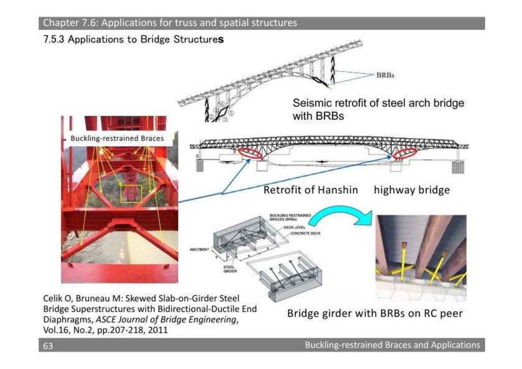
местоположение, и склонность. Xiang и другие [39 < https: // www. mdpi. com/2075-5309/12/12/2147 >] исследовал результат(влияние) BRB распределения на
сейсмическом выполнении(работе) retrofitted многоэтажного железобетона, высоко соединяют пирса. Однако, заявление(применение) BRB в стальном мосте
арки(дуги) связки редко (Celik и другие [40 < https: // www. mdpi. com/2075-5309/12/12/2147 >]).
Цели этой бумаги состоят в том, чтобы исследовать специальный сейсмический ответ длительного периода, арка(дуга) связки стали соединяет и представляет
BRBS в сокращение вибрации стального моста арки(дуги) связки в около областей ошибки. Во-первых, девять движений основания(земли) с различными
характеристиками отобраны от ПЭРА(РАВНОГО ПО ПОЛОЖЕНИЮ), база данных [< https: // www. mdpi. com/2075-5309/12/12/2147 >], и их различия
проанализирована спектром ответа. Впоследствии, при взятии стального моста арки(дуги) связки как объект(цель) исследования, закон ответа моста под вперед directivity pulsed, брос& - шаг pulsed, и не - pulsed движения проанализированы с упруги - пластмассовым методом анализа истории времени. Наконец,
сейсмический метод уменьшения использования BRB, чтобы заменить buckling-склонные компоненты предложен и проверен. Результаты показывают, что
внутренняя сила и смещение ребер арки(дуги) может быть уменьшена, заменяя часть нормальных брусков(баров) с BRBS, который является более видным при
действии движения основания(земли) pulsed.
2. Почти Движения Основания(земли) Ошибки
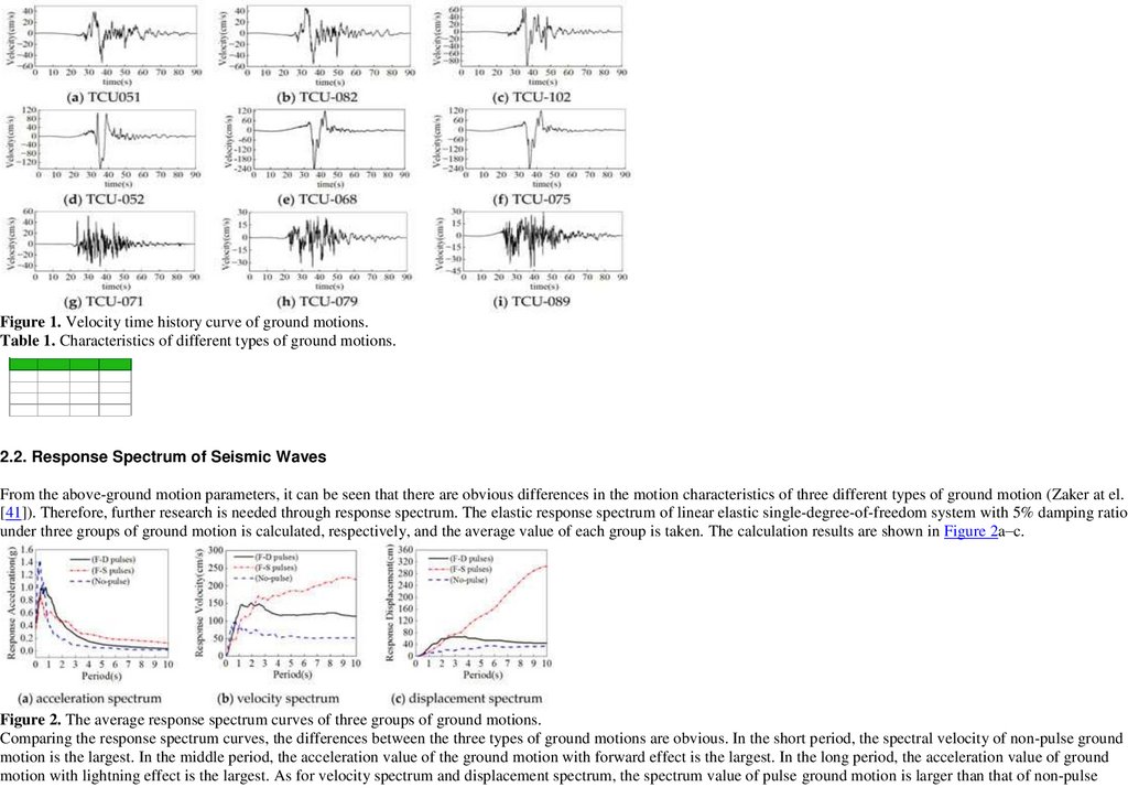
2.1. Отобранные Сейсмические Волны
Chi-Chi землетрясение в Tайване в 1999 - типичное большое землетрясение около ошибки. В этой бумаге, девять движений основания(земли) различных типов в
этом землетрясении приняты от самой последней базы данных ПЭРА(РАВНОГО ПО ПОЛОЖЕНИЮ) NGA-ЗАПАД 2. Принципы выбора движения
основания(земли) следующие: (1) ошибка - в пределах 20 км; и (2) пиковых ускорение и скорость большее чем 100 cm/s2 и 30 cm/s, соответственно. Три группы
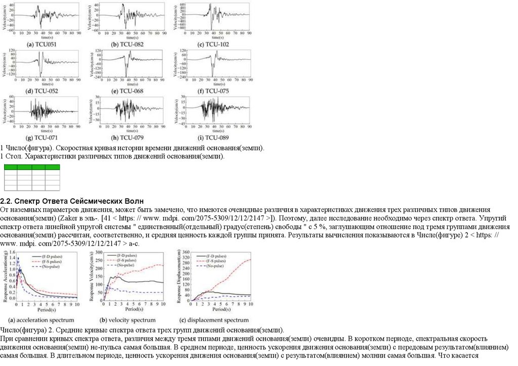
истории времени скорости движения основания(земли) с различными характеристиками показываются в Числе(фигуре) 1 < https: // www. mdpi. com/20755309/12/12/2147 > " меня ". Первая группа содержит три сейсмических волны, TCU-051, TCU-082, и TCU-102, представляя F-D производят сейсмические волны;
вторая группа содержит три сейсмических волны, TCU-052, TCU-068, и TCU-075, представляя F-S производят сейсмические волны; третья группа содержит три
сейсмических волны, TCU-071, TCU-089, и TCU-079, представляя не-пульс производят сейсмические волны. Основные свойства движений основания(земли), типа
самого близкого расстояния к ошибке разрывают (Rrup), пиковое ускорение основания(земли) (PGA), пик основывает скорость (PGV), пиковое смещение
основания(земли) (PGD), PGV/PGA, и пульс, период (Tp) внесен в список в Столе 1 < https: // www. mdpi. com/2075-5309/12/12/2147 >. PGV/PGA обычно
принимается, поскольку параметр пульса в изучении к preliminarily судит силу скоростного пульса. Согласно предварительному суждению, результат(влияние)
пульса отобранных P-S движений самый сильный, сопровожден в соответствии с P-D движениями. Напротив, обычный не движение основания(земли) пульса
нежно.
21.
1 Число(фигура). Скоростная кривая истории времени движений основания(земли).1 Стол. Характеристики различных типов движений основания(земли).
2.2. Спектр Ответа Сейсмических Волн
От наземных параметров движения, может быть замечено, что имеются очевидные различия в характеристиках движения трех различных типов движения
основания(земли) (Zaker в эль-. [41 < https: // www. mdpi. com/2075-5309/12/12/2147 >]). Поэтому, далее исследование необходимо через спектр ответа. Упругий
спектр ответа линейной упругой системы " единственный(отдельный) градус(степень) свободы " с 5 %, заглушающим отношение под тремя группами движения
основания(земли) рассчитан, соответственно, и средняя ценность каждой группы принята. Результаты вычисления показываются в Числе(фигуре) 2 < https: //
www. mdpi. com/2075-5309/12/12/2147 > a-c.
Число(фигура) 2. Средние кривые спектра ответа трех групп движений основания(земли).
При сравнении кривых спектра ответа, различия между тремя типами движений основания(земли) очевидны. В коротком периоде, спектральная скорость
движения основания(земли) не-пульса самая большая. В среднем периоде, ценность ускорения движения основания(земли) с передовым результатом(влиянием)
самая большая. В длительном периоде, ценность ускорения движения основания(земли) с результатом(влиянием) молнии самая большая. Что касается
22.
скоростного спектра и спектра смещения, ценность спектра движения основания(земли) пульса большая чем таковой движения основания(земли) не-пульса вдлительном периоде. Вообще, компоненты с низкой частотой движения основания(земли) пульса относительно богаты, на который нужно обратить внимание в
проекте длительного периода на структуры около ошибок.
Пиковые ускорение из девяти первичных сейсмических волн отрегулированы(приспособлены) в отношении Китайского сейсмического кодекса для мостов (Wu в
эль-. [< Https: // www. mdpi. com/2075-5309/12/12/2147 >]). Редкие землетрясения в Китайском кодексе подобны ASCE максимуму, рассматриваемому
землетрясениями. Изучаемый мост находится в зоне октавы, так что пиковое ускорение в редких землетрясениях было отрегулировано(приспособлено) к 400
cm/s2.
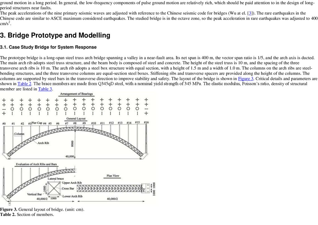
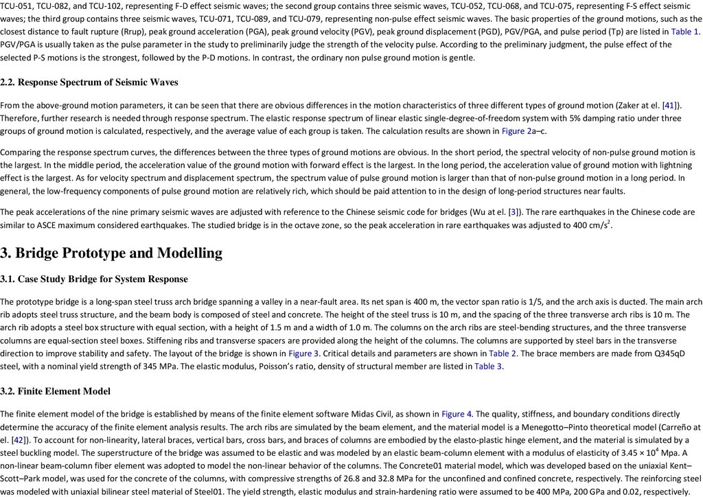
3. Опытный образец Моста и Modelling
3.1. Мост Изучения Случая для Ответа Системы
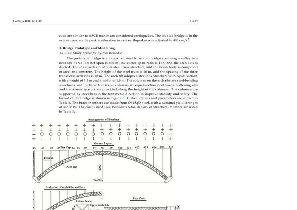
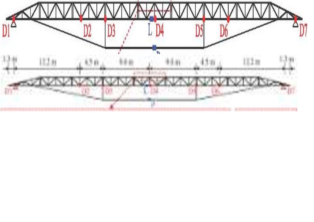
Мост опытного образца - стальной мост арки(дуги) связки с длинным промежутком, охватывающий долину в почти области ошибки. Чистый промежуток - 400
м., векторное отношение промежутка - 1/5, и ось арки(дуги) - ducted. Главное ребро арки(дуги) принимает стальную структуру связки, и орган(тело) луча
составлен из стали и бетона. Высота стальной связки - 10 м., и интервал из трех поперечных ребер арки(дуги) - 10 м. Ребро арки(дуги) принимает стальную
структуру коробки с равной секцией, с высотой 1.5 м. и ширины 1.0 м. Колонки на ребрах арки(дуги) - изгибающиеся сталь структуры, и три поперечных колонки
- стальные коробки с равной секцией. Напряжение ребра и поперечные распорные детали обеспечивается по высоте колонок. Колонки поддержаны стальными
брусками(барами) в поперечном руководстве(направлении), чтобы улучшить стабильность и безопасность. Расположение моста показывается в Числе(фигуре) 3 <
https: // www. mdpi. com/2075-5309/12/12/2147 >. Критические детали и параметры показываются в Столе 2 < https: // www. mdpi. com/2075-5309/12/12/2147 >.
Члены фигурной скобки сделаны от Q345qD стали, с номинальной силой урожая 345 MPA. Упругий модуль, отношение Поиссона, плотность структурного члена
внесен в список в Столе 3 < https: // www. mdpi. com/2075-5309/12/12/2147 >.
Число(фигура) 3. Общее расположение моста. (Единица: cm).
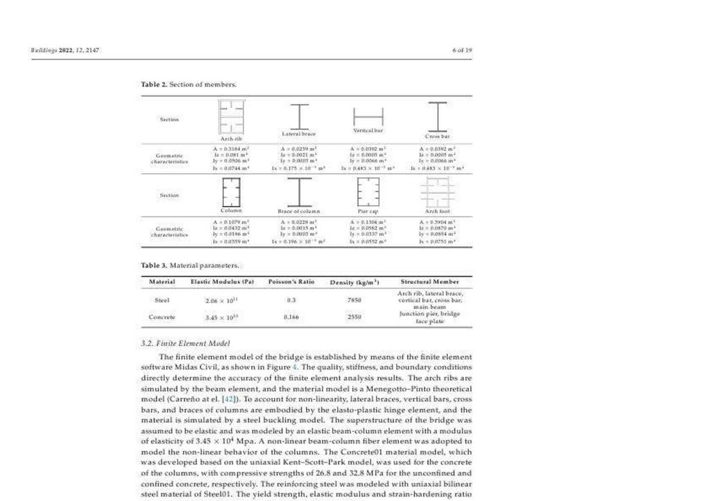
Стол 2. Секция членов.
23.
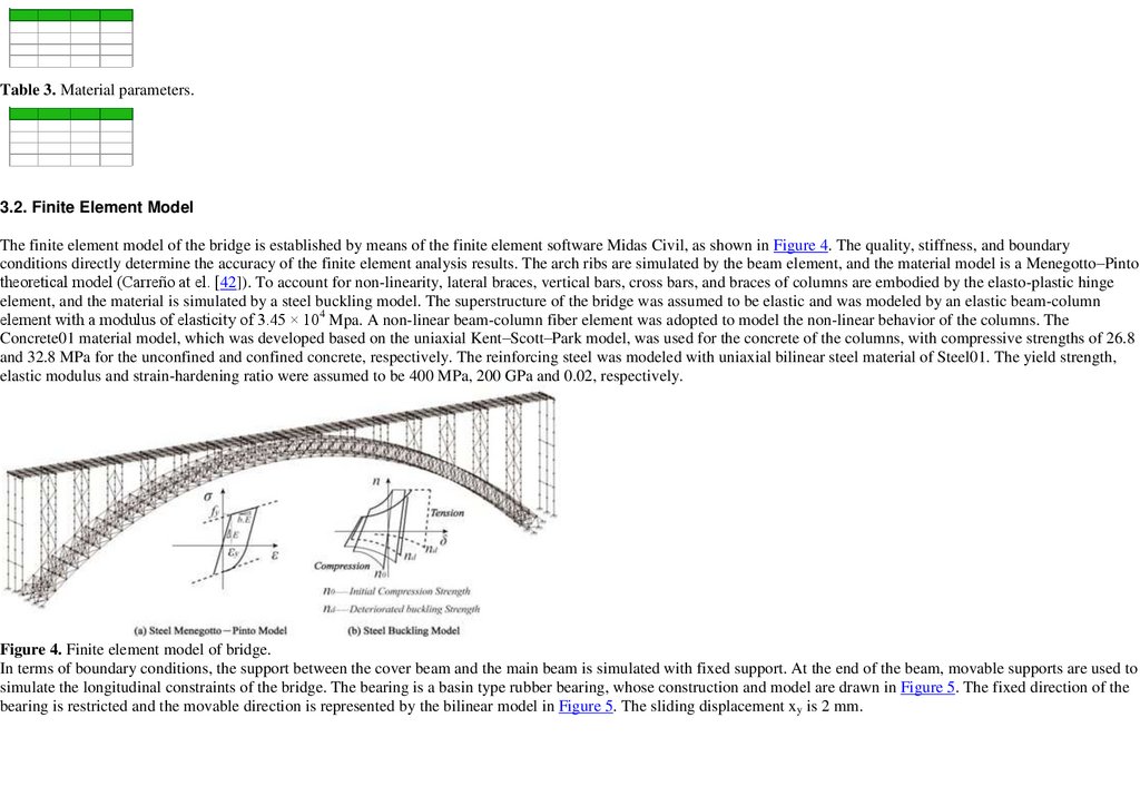
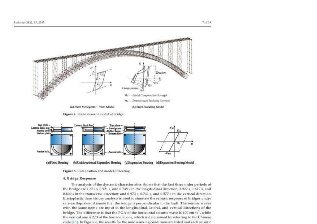
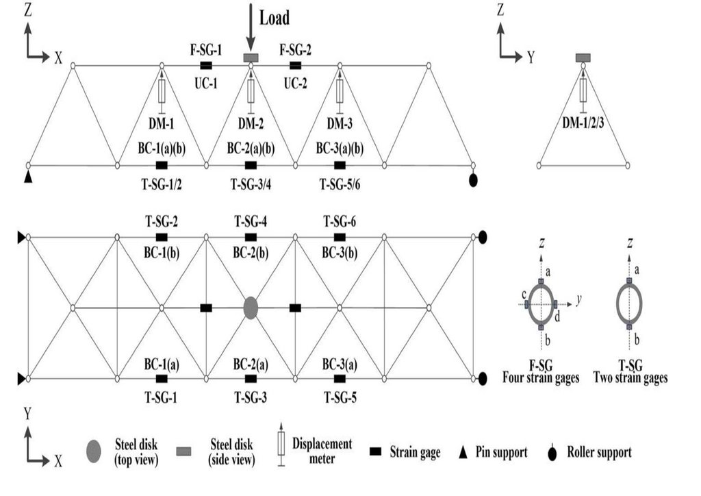
Стол 3. Материальные параметры.3.2. Конечная Модель Элемента
Конечная модель элемента моста установлена посредством конечного программного обеспечения элемента Midas Гражданский, как показано в
Числе(фигуре) 4 < https: // www. mdpi. com/2075-5309/12/12/2147 >. Качество, неподвижность, и граничные условия(состояния) непосредственно
определяет точность конечных результатов анализа элемента. Ребра арки(дуги) моделируются элементом луча, и материальная модель Menegotto-Pinto теоретическая модель (Carre? O в эль-. [42 < https: // www. mdpi. com/2075-5309/12/12/2147 >]). Чтобы составлять не-линейность,
боковые фигурные скобки, вертикальные бруски(бары), взаимные бруски(бары), и фигурные скобки колонок реализованы elasto-пластмассой
элементом стержня, и материал моделируется сталью buckling модель. Суперструктура моста была принята, чтобы быть упругой и была
смоделирована упругим элементом колонки луча с модулем эластичности 3.45? 104 Mpa. Нелинейный элемент волокна колонки луча был принят к
модели нелинейное поведение колонок. Concrete01 материальная модель, которая была развита основанной на uniaxial Kent-Scott-Park модель,
использовалась для бетона колонок, со сжимающими силами 26.8 и 32.8 MPA для неограниченного(незаключенного) и ограничена(заключена)
бетон, соответственно. Сталь укрепления была смоделирована с uniaxial bilinear стальной материал Steel01. Сила урожая, упругий модуль и
укрепляющееся напряжение отношение была принята, чтобы быть 400 MPA, 200 GPA и 0.02, соответственно.
Число(фигура) 4. Конечная модель элемента моста.
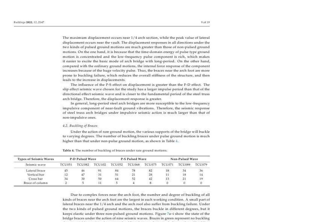
В терминах граничных условий(состояний), поддержка между лучом покрытия и главным лучом моделируется с установленной поддержкой. В конце луча,
подвижные поддержки используются, чтобы моделировать продольные ограничения моста. Отношение(поведение) - бассейн, напечатают отношение(поведение)
каучука, чей строительство и модель оттянуто в Числе(фигуре) 5 < https: // www. mdpi. com/2075-5309/12/12/2147 >. Установленное руководство(направление)
24.
отношения(поведения) ограничено, и подвижное руководство(направление) представлено bilinear моделью в Числе(фигуре) 5 < https: // www. mdpi. com/20755309/12/12/2147 >. Скользящее смещение xy - 2 mm.Число(фигура) 5. Состав и модель отношения(поведения).
4. Ответ Моста
Анализ динамических характеристик показывает, что первые три заказ(порядок) периоды моста 1.651 s, 0.921 s, и 0.745 s в продольном руководстве(направлении);
3.927 s, 1.612 s, и 0.809 s в поперечном руководстве(направлении); и 0.973 s, 0.741 s, и 0.577 s в вертикальном руководстве(направлении). Elastoplastic анализ
истории времени используется, чтобы моделировать сейсмический ответ мостов под редкими землетрясениями. Предположите, что мост перпендикулярен к
ошибке. Сейсмические волны с тем же самым названием(именем) - вход в продольных, боковых, и вертикальных руководствах(направлениях) моста. Различие то, что PGA горизонтальной сейсмической волны является 400 cm/s2, в то время как вертикальный - 2/3 горизонтального, который определен что касается
Китайского кодекса [43 < https: // www. mdpi. com/2075-5309/12/12/2147 >]. В Числе(фигуре) 6 < https: // www. mdpi. com/2075-5309/12/12/2147 >, результаты для
девяти рабочих условий(состояний) внесены в список, и каждая сейсмическая волна представляет тот, работающий условие(состояние). Три условия(состояния),
TCU-051, TCU-082, и TCU-102, представляют ответ моста под F-D, производят сейсмические волны, TCU-052, TCU-068, и TCU-075 представляют ответ моста под
F-S, производят сейсмические волны, и TCU-071, TCU-089, и TCU-079 представляют ответ моста под не - pulsed, производят сейсмические волны. Согласно
внутренней силе и смещению ключевых частей, типа фута(ноги) арки(дуги), основания арки(дуги), и секции арки(дуги) 1/4, и buckling боковых фигурных скобок,
вертикальных брусков(баров), взаимных брусков(баров) и фигурных скобок колонок, закон ответа моста получен в итоге.
25.
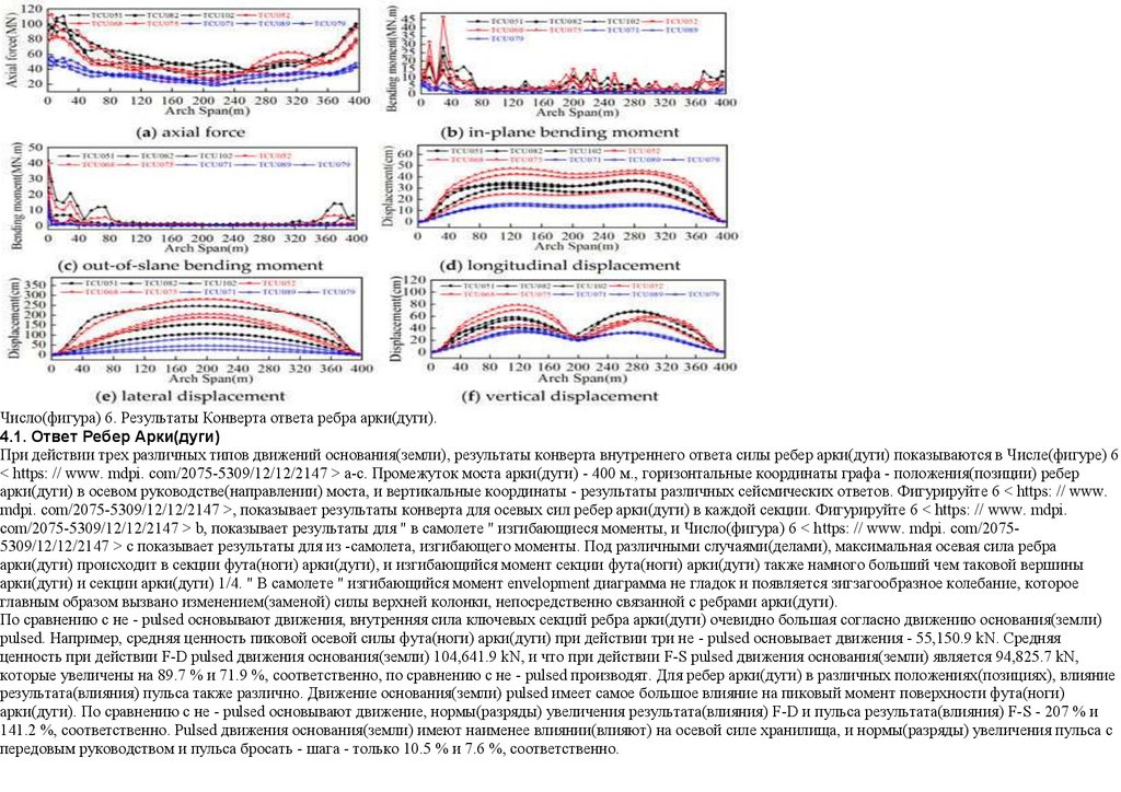
Число(фигура) 6. Результаты Конверта ответа ребра арки(дуги).4.1. Ответ Ребер Арки(дуги)
При действии трех различных типов движений основания(земли), результаты конверта внутреннего ответа силы ребер арки(дуги) показываются в Числе(фигуре) 6
< https: // www. mdpi. com/2075-5309/12/12/2147 > a-c. Промежуток моста арки(дуги) - 400 м., горизонтальные координаты графа - положения(позиции) ребер
арки(дуги) в осевом руководстве(направлении) моста, и вертикальные координаты - результаты различных сейсмических ответов. Фигурируйте 6 < https: // www.
mdpi. com/2075-5309/12/12/2147 >, показывает результаты конверта для осевых сил ребер арки(дуги) в каждой секции. Фигурируйте 6 < https: // www. mdpi.
com/2075-5309/12/12/2147 > b, показывает результаты для " в самолете " изгибающиеся моменты, и Число(фигура) 6 < https: // www. mdpi. com/20755309/12/12/2147 > c показывает результаты для из -самолета, изгибающего моменты. Под различными случаями(делами), максимальная осевая сила ребра
арки(дуги) происходит в секции фута(ноги) арки(дуги), и изгибающийся момент секции фута(ноги) арки(дуги) также намного больший чем таковой вершины
арки(дуги) и секции арки(дуги) 1/4. " В самолете " изгибающийся момент envelopment диаграмма не гладок и появляется зигзагообразное колебание, которое
главным образом вызвано изменением(заменой) силы верхней колонки, непосредственно связанной с ребрами арки(дуги).
По сравнению с не - pulsed основывают движения, внутренняя сила ключевых секций ребра арки(дуги) очевидно большая согласно движению основания(земли)
pulsed. Например, средняя ценность пиковой осевой силы фута(ноги) арки(дуги) при действии три не - pulsed основывает движения - 55,150.9 kN. Средняя
ценность при действии F-D pulsed движения основания(земли) 104,641.9 kN, и что при действии F-S pulsed движения основания(земли) является 94,825.7 kN,
которые увеличены на 89.7 % и 71.9 %, соответственно, по сравнению с не - pulsed производят. Для ребер арки(дуги) в различных положениях(позициях), влияние
результата(влияния) пульса также различно. Движение основания(земли) pulsed имеет самое большое влияние на пиковый момент поверхности фута(ноги)
арки(дуги). По сравнению с не - pulsed основывают движение, нормы(разряды) увеличения результата(влияния) F-D и пульса результата(влияния) F-S - 207 % и
141.2 %, соответственно. Pulsed движения основания(земли) имеют наименее влиянии(влияют) на осевой силе хранилища, и нормы(разряды) увеличения пульса с
передовым руководством и пульса бросать - шага - только 10.5 % и 7.6 %, соответственно.
26.
В терминах деформации, распределение продольной и вертикальной деформации подобно. Фигурируйте 6 < https: // www. mdpi. com/2075-5309/12/12/2147 > d-f,показывают результаты конверта смещения секции ребра арки(дуги) относительно основания(земли) в продольных, поперечных, и вертикальных
руководствах(направлениях), соответственно. Максимальное смещение происходит около секции арки(дуги) 1/4, в то время как пиковая ценность бокового
смещения происходит около хранилища. Ответы смещения во всех руководствах(направлениях) под двумя видами движений основания(земли) pulsed намного
большие чем таковые не - pulsed, основывают движения. С одной стороны, то, потому что это, энергия области времени движения основания(земли) типа пульса
сконцентрирована и компонент пульса с низкой частотой, богато, который делает более легким возбудить основной способ моста арки(дуги) с длительным
периодом. С другой стороны, по сравнению с обычными движениями основания(земли), внутренний ответ силы составляющих увеличений из-за огромного
скоростного пульса. Таким образом, фигурные скобки около фута(ноги) арки(дуги) более склонные к buckling отказу(неудаче), который уменьшает полную
неподвижность структуры, и затем ведет к увеличению в смещениях.
Влияние результата(влияния) P-S на смещение большее чем результат(влияние) F-D. Результат(влияние) промаха сейсмическая волна, выбранная для изучения
имеет больший импульс периодом чем таковой направленного результата(влияния) сейсмическая волна и ближе к фундаментальному периоду стального моста
арки(дуги) связки. Поэтому, ответ смещения больший.
Вообще, длительный период мосты арки(дуги) стали более восприимчив к низкой частоте impulsive компонент почти колебаний основания(земли) ошибки.
Поэтому, сейсмический ответ стальных мостов арки(дуги) связки при impulsive сейсмическом действии намного больший чем таковой не - impulsive.
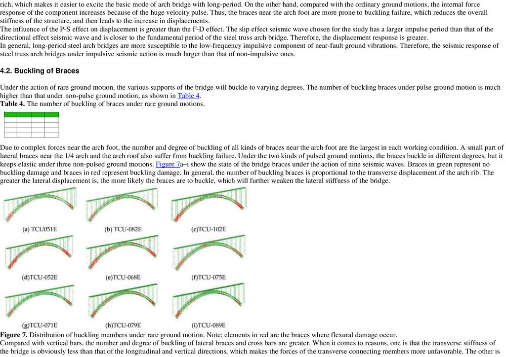
4.2. Buckling Фигурных скобок
При действии редкого движения основания(земли), различные поддержки моста будут застежка к различным степеням. Номер(число) buckling фигурных скобок
согласно движению основания(земли) пульса - намного выше чем это согласно движению основания(земли) не-пульса, как показано в Столе 4 < https: // www.
mdpi. com/2075-5309/12/12/2147 >.
Стол 4. Номер(число) buckling фигурных скобок согласно редким движениям основания(земли).
Для сложных сил около фута(ноги) арки(дуги), номер(число) и градус(степень) buckling всех видов фигурных скобок около фута(ноги) арки(дуги) самый большой
в каждом рабочем условии(состоянии). Маленькая часть боковых фигурных скобок около арки(дуги) 1/4 и крыши арки(дуги) также страдает от buckling
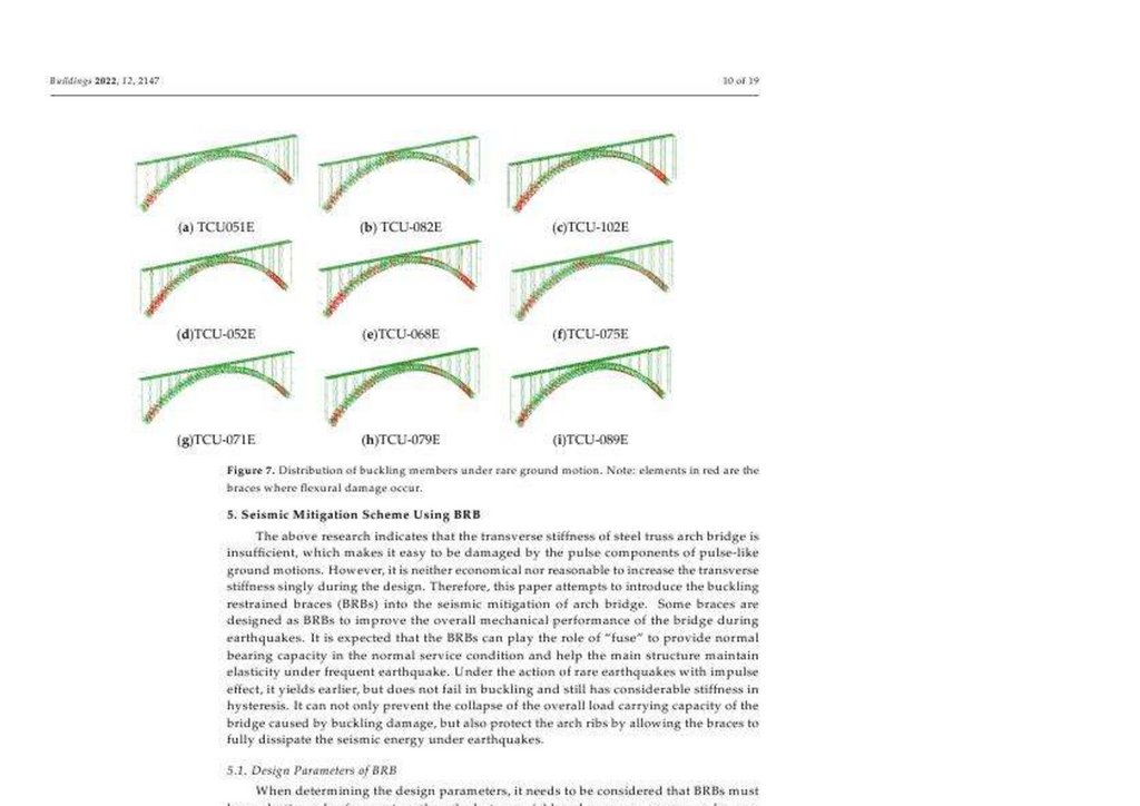
отказа(неудачи). Под двумя видами pulsed основывают движения, застежка фигурных скобок в различных градусах(степенях), но это держит резинку под три не pulsed, основывают движения. Изобразите 7 < https: // www. mdpi. com/2075-5309/12/12/2147 > выставку " я " государство(состояние) фигурных скобок моста при
действии девяти сейсмических волн. Фигурные скобки в зеленом не представляют никакое повреждение(ущерб) buckling, и фигурные скобки в красном
представляют повреждение(ущерб) buckling. Вообще, номер(число) buckling фигурных скобок пропорционален поперечному смещению ребра арки(дуги).
Больший боковое смещение, более вероятно, что фигурные скобки к застежке, которая далее ослабит боковую неподвижность моста.
27.
Число(фигура) 7. Распределение buckling членов согласно редкому движению основания(земли). Обратите внимание: элементы в красном - фигурные скобки, гдеповреждение(ущерб) flexural происходит.
По сравнению с вертикальными брусками(барами), номер(число) и градус(степень) buckling боковых фигурных скобок и взаимных брусков(баров) больший.
Когда это прибывает в причины, каждый - то, что поперечная неподвижность моста является очевидно меньше чем таковой продольных и вертикальных
руководств(направлений), который делает силы из поперечных членов соединения более неблагоприятными. Другой - то, что сила проекта поперечных и
взаимных членов бруска(бара) является меньшей чем таковой вертикальных брусков(баров). Поэтому, необходимо сосредоточиться на поперечном сейсмическом
ответе и сейсмических мерах уменьшения больших мостов арки(дуги) связки стали промежутка.
В резюме, осевая сила, изгибая момент и ответ смещения во всех трех руководствах(направлениях) ребер арки(дуги) знаменательно большая при pulsed
сейсмических волнах, сравненных с не - pulsed сейсмические волны. От перспективы фигурных скобок, большее количество buckling повреждение(ущерб)
происходит в фигурных скобках при действии pulsed сейсмических волн.
5. Сейсмическая Схема Уменьшения, использующая BRB
Вышеупомянутое исследование указывает, что поперечная неподвижность стального моста арки(дуги) связки недостаточна, который делает легким быть
поврежденным компонентами пульса пульс-подобных движений основания(земли). Однако, это не является ни экономическим, ни разумным увеличить
поперечную неподвижность отдельно в течение проекта. Поэтому, эта бумага пытается представлять buckling ограниченные фигурные скобки (BRBS) в
сейсмическое уменьшение моста арки(дуги). Некоторые фигурные скобки разработаны(предназначены) как BRBS, чтобы улучшить полное механическое
выполнение(работу) моста в течение землетрясений. Ожидается, что BRBS может играть роль ―плавкого предохранителя‖, чтобы обеспечить, нормальная
способность(вместимость) отношения(поведения) в нормальном обслуживании(службе) создает условия и помогает главной структуре обслужить(поддержать)
эластичность под частым землетрясением. При действии редких землетрясений с результатом(влиянием) импульса, это уступает ранее, но не терпит неудачу в
buckling и все еще имеет значительную неподвижность в гистерезисе. Это не может только предотвращать крах полного груза, несущего
способность(вместимость) моста, вызванного повреждением(ущербом) buckling, но также и защищать ребра арки(дуги), позволяя фигурные скобки полностью
рассеять сейсмическую энергию под землетрясениями.
5.1. Параметры Проекта BRB
При определении параметров проекта, требоваться рассмотреться, что BRBS должен держать резинку под частым землетрясением, но может выдавать(уступать) и
потреблять энергию под редким землетрясением. Во-первых, при рассмотрении условия(состояния) частых землетрясений, PGA 9 сейсмических
отчетов(рекордов) отрегулирован(приспособлен) к 0.1 g. Тогда, нелинейный анализ истории времени выполнен. Максимальная осевая сила фигурных скобок
28.
согласно различным движениям основания(земли) показывается в Столе 5 < https: // www. mdpi. com/2075-5309/12/12/2147 >, и результаты вычисленияиспользуются как главное основание для предварительного проекта. После развертывания BRBS, члены моста и полная способность(вместимость) груза не
должны отличиться много от такового моста опытного образца.
Стол 5. Максимальная осевая сила членов под частыми землетрясениями (kN).
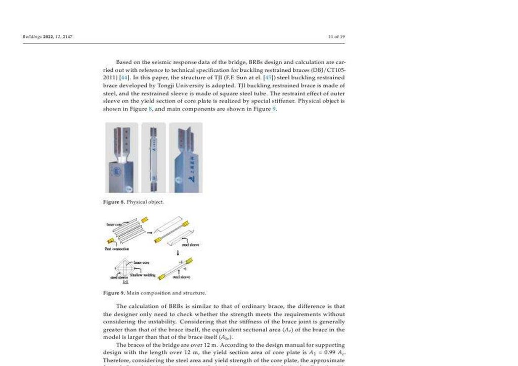
Основанный на сейсмических данных ответа моста, BRBS проект и вычисление выполнены в отношении технической спецификации для buckling ограниченные
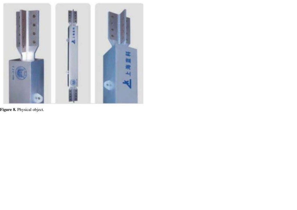
фигурные скобки (DBJ/CT105-2011 [) 44 < https: // www. mdpi. com/2075-5309/12/12/2147 >]. В этой бумаге, структура TJI (F.F. Солнце в эль-. [45 < https: // www.
mdpi. com/2075-5309/12/12/2147 >]) сталь buckling ограниченная фигурная скобка, развитая Tongji Университетом принята. TJI buckling ограниченная фигурная
скобка сделан стали, и ограниченный рукав сделан квадратной стальной трубы. Результат(влияние) ограничения внешнего рукава на секции урожая основной
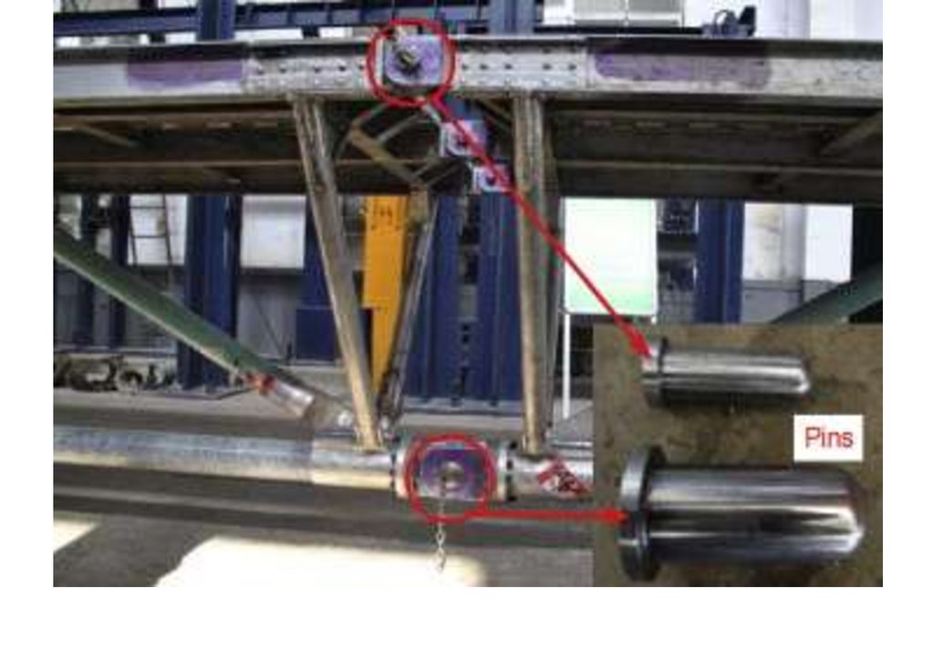
пластины осознан специальным stiffener. Физический объект(цель) показывается в Числе(фигуре) 8 < https: // www. mdpi. com/2075-5309/12/12/2147 >, и главные
компоненты показываются в Числе(фигуре) 9 < https: // www. mdpi. com/2075-5309/12/12/2147 >.
Число(фигура) 8. Физический объект(цель).
29.
Число(фигура) 9. Главный состав и структура.Вычисление BRBS подобно таковому обычной фигурной скобки, различие - то, что проектировщик только должен проверить, встречает(выполняет ли) сила
требования без того, чтобы рассмотреть неустойчивость. Рассмотрение, что неподвижность фигурной скобки объединенный является вообще большей чем
таковой фигурной скобки непосредственно, эквивалентная частная(секционная) область (Ae) фигурной скобки в модели, больший чем таковой фигурной скобки
непосредственно (Эйб).
Фигурные скобки моста - более чем 12 м. Согласно руководству проекта для поддержки проекта с длиной более чем 12 м., область секции урожая основной
пластины - От A1 до 0.99 Ae. Поэтому, при рассмотрении стальной области и силы урожая основной пластины, приблизительная формула для вычисления
максимального проекта, несущего способность(вместимость) получена как Уравнение (1):
Nb1 = 0. 9fyA1 = 0. 9fy0. 99Abe? 0. 891fyAe
( 1)
При рассмотрении частой комбинации груза землетрясения, ценность проекта максимальной напряженности и сжатия осевая сила BRBS должна
встретить(выполнить) требования Уравнения (2):
N? Nb1 /? Re? 1. 188fyAe
( 2)
Где N представляет ценность проекта BRBS осевой силы, Nb1 представляет проект, несущий способность(вместимость) BRBS,? Re представляет сейсмический
коэффициент регулирования, вообще 0.75 согласно Технической спецификации для buckling ограниченные фигурные скобки (DBJ/CT105-2011).
Через вышеупомянутые методы, спецификации и измерения BRBS могут быть полученный preliminarily. Затем, урожай, несущий способность(вместимость)
модели рассчитан Уравнением (3) как основание конечного анализа элемента.
Nby =? YfyA1
( 3)
Где Nby представляет урожай, несущий способность(вместимость) BRBS,? Y представляет коэффициент силы высшего качества основной стали пластины.
30.
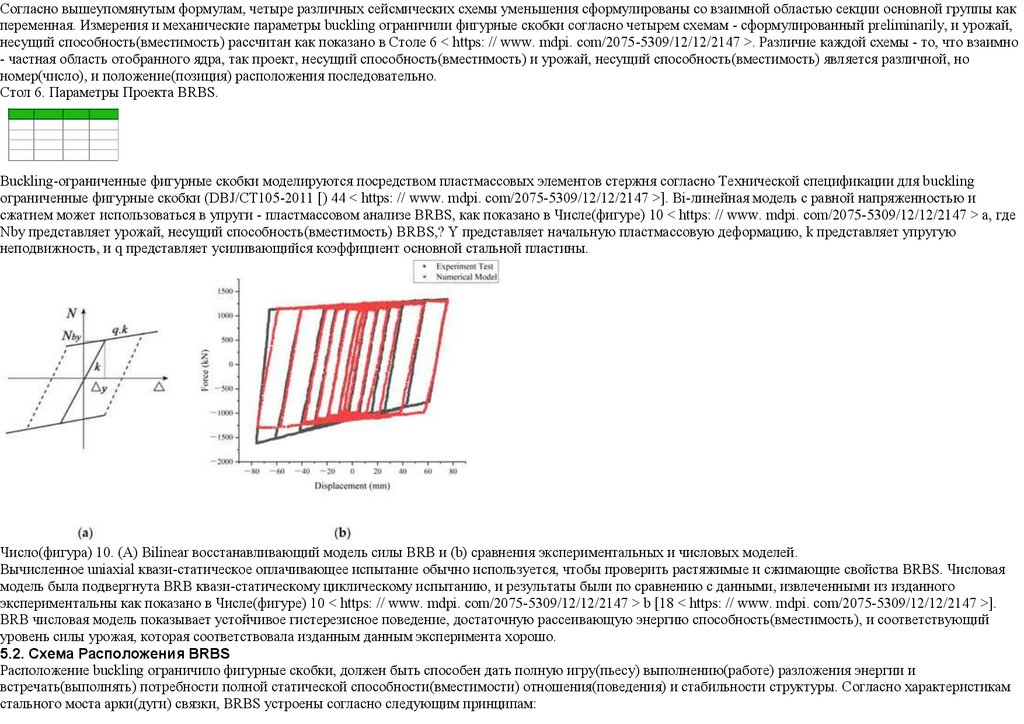
Согласно вышеупомянутым формулам, четыре различных сейсмических схемы уменьшения сформулированы со взаимной областью секции основной группы какпеременная. Измерения и механические параметры buckling ограничили фигурные скобки согласно четырем схемам - сформулированный preliminarily, и урожай,
несущий способность(вместимость) рассчитан как показано в Столе 6 < https: // www. mdpi. com/2075-5309/12/12/2147 >. Различие каждой схемы - то, что взаимно
- частная область отобранного ядра, так проект, несущий способность(вместимость) и урожай, несущий способность(вместимость) является различной, но
номер(число), и положение(позиция) расположения последовательно.
Стол 6. Параметры Проекта BRBS.
Buckling-ограниченные фигурные скобки моделируются посредством пластмассовых элементов стержня согласно Технической спецификации для buckling
ограниченные фигурные скобки (DBJ/CT105-2011 [) 44 < https: // www. mdpi. com/2075-5309/12/12/2147 >]. Bi-линейная модель с равной напряженностью и
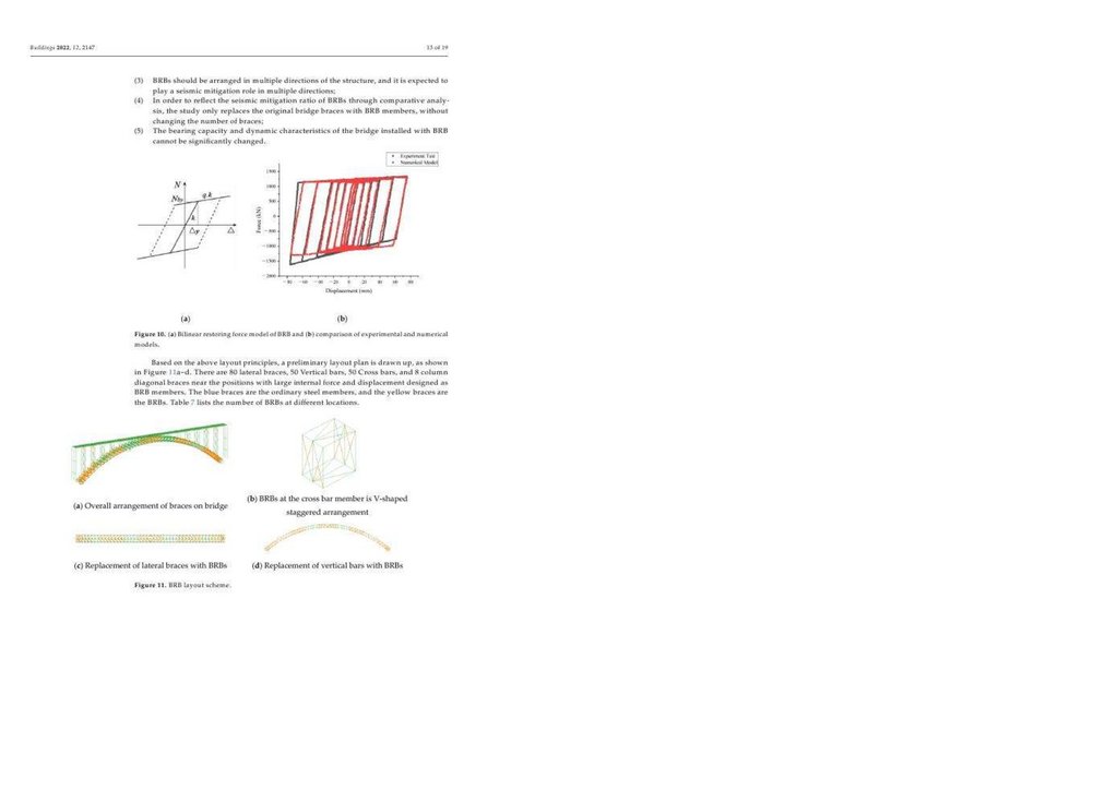
сжатием может использоваться в упруги - пластмассовом анализе BRBS, как показано в Числе(фигуре) 10 < https: // www. mdpi. com/2075-5309/12/12/2147 > a, где
Nby представляет урожай, несущий способность(вместимость) BRBS,? Y представляет начальную пластмассовую деформацию, k представляет упругую
неподвижность, и q представляет усиливающийся коэффициент основной стальной пластины.
Число(фигура) 10. (A) Bilinear восстанавливающий модель силы BRB и (b) сравнения экспериментальных и числовых моделей.
Вычисленное uniaxial квази-статическое оплачивающее испытание обычно используется, чтобы проверить растяжимые и сжимающие свойства BRBS. Числовая
модель была подвергнута BRB квази-статическому циклическому испытанию, и результаты были по сравнению с данными, извлеченными из изданного
экспериментальны как показано в Числе(фигуре) 10 < https: // www. mdpi. com/2075-5309/12/12/2147 > b [18 < https: // www. mdpi. com/2075-5309/12/12/2147 >].
BRB числовая модель показывает устойчивое гистерезисное поведение, достаточную рассеивающую энергию способность(вместимость), и соответствующий
уровень силы урожая, которая соответствовала изданным данным эксперимента хорошо.
5.2. Схема Расположения BRBS
Расположение buckling ограничило фигурные скобки, должен быть способен дать полную игру(пьесу) выполнению(работе) разложения энергии и
встречать(выполнять) потребности полной статической способности(вместимости) отношения(поведения) и стабильности структуры. Согласно характеристикам
стального моста арки(дуги) связки, BRBS устроены согласно следующим принципам:
31.
( 1)BRBS должны быть устроен около секций с большой силой и относительным смещением;
( 2)
Расположение поддержек включает единственный(отдельный) диагональный бодрящий, V-форменный или форма herringbone, но они не должны быть
устроены во взаимной форме X-форменный;
( 3)
BRBS должен быть устроен в многократных руководствах(направлениях) структуры, и ожидается играть сейсмическую роль уменьшения в многократных
руководствах(направлениях);
( 4)
Чтобы отражать сейсмическое отношение уменьшения BRBS через сравнительный анализ, изучение только заменяет первоначальные фигурные скобки
моста BRB членами, без того, чтобы изменить номер(число) фигурных скобок;
( 5)
Способность(вместимость) отношения(поведения) и динамические характеристики моста, установленного с BRB не может быть знаменательно
изменена(заменена).
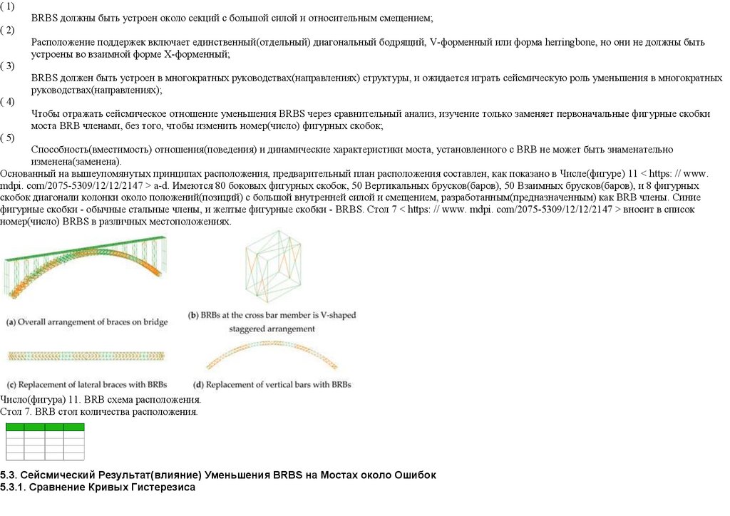
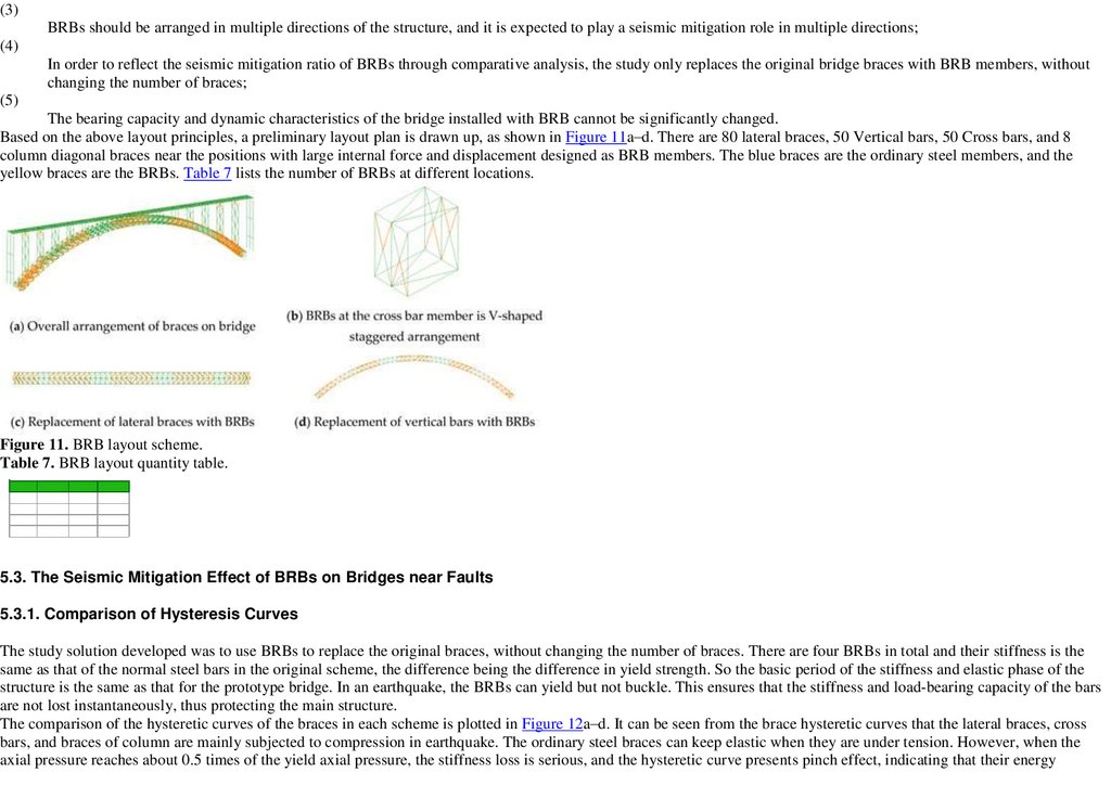
Основанный на вышеупомянутых принципах расположения, предварительный план расположения составлен, как показано в Числе(фигуре) 11 < https: // www.
mdpi. com/2075-5309/12/12/2147 > a-d. Имеются 80 боковых фигурных скобок, 50 Вертикальных брусков(баров), 50 Взаимных брусков(баров), и 8 фигурных
скобок диагонали колонки около положений(позиций) с большой внутренней силой и смещением, разработанным(предназначенным) как BRB члены. Синие
фигурные скобки - обычные стальные члены, и желтые фигурные скобки - BRBS. Стол 7 < https: // www. mdpi. com/2075-5309/12/12/2147 > вносит в список
номер(число) BRBS в различных местоположениях.
Число(фигура) 11. BRB схема расположения.
Стол 7. BRB стол количества расположения.
5.3. Сейсмический Результат(влияние) Уменьшения BRBS на Мостах около Ошибок
5.3.1. Сравнение Кривых Гистерезиса
32.
Развитое решение изучения состояло в том, чтобы использовать BRBS, чтобы заменить первоначальные фигурные скобки, без того, чтобы изменить номер(число)фигурных скобок. Имеются четыре BRBS всего, и их неподвижность - тот же самый как таковой нормальных стальных брусков(баров) в первоначальной схеме,
различие, являющееся различием в силе урожая. Так что основной период неподвижности и упругой стадии структуры - тот же самый как это для моста опытного
образца. В землетрясении, BRBS может выдавать(уступать), но не застежку. Это гарантирует, что неподвижность и несущая груз способность(вместимость)
брусков(баров) не потеряна мгновенно, таким образом при защите главной структуры.
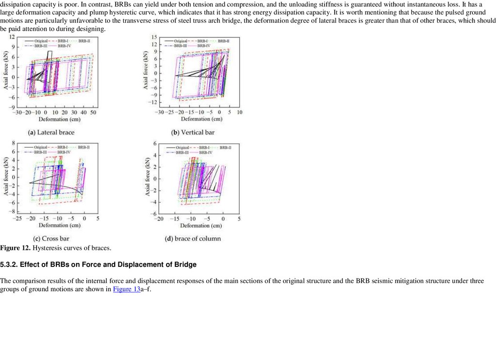
Сравнение гистерезисных кривых фигурных скобок в каждой схеме подготовлено в Числе(фигуре) 12 < https: // www. mdpi. com/2075-5309/12/12/2147 > a-d. Это
может быть замечено от фигурной скобки гистерезисные кривые, что боковые фигурные скобки, взаимные бруски(бары), и фигурные скобки колонки главным
образом подвергнуты сжатию в землетрясении. Обычные стальные фигурные скобки могут держать резинку, когда они находятся под напряженностью. Однако,
когда осевое давление достигает приблизительно 0.5 раз урожая, осевое давление, потеря неподвижности серьезно, и гистерезисный результат(влияние)
повышения подарков кривой, указывая, что их способность(вместимость) разложения энергии является бедной. Напротив, BRBS может уступать и,
напряженностью и сжатием, и разгружающаяся неподвижность гарантируется без мгновенной потери. Это имеет большую способность(вместимость) деформации
и пухлую гистерезисную кривую, которая указывает, что это имеет сильную способность(вместимость) разложения энергии. Это стоит упоминать, что, потому что
движения основания(земли) pulsed особенно неблагоприятны поперечному напряжению стального моста арки(дуги) связки, градус(степень) деформации боковых
фигурных скобок больший чем таковой других фигурных скобок, на которые нужно обратить внимание в течение проектирования.
Число(фигура) 12. Кривые Гистерезиса фигурных скобок.
5.3.2. Результат(влияние) BRBS на Силе и Смещении Моста
33.
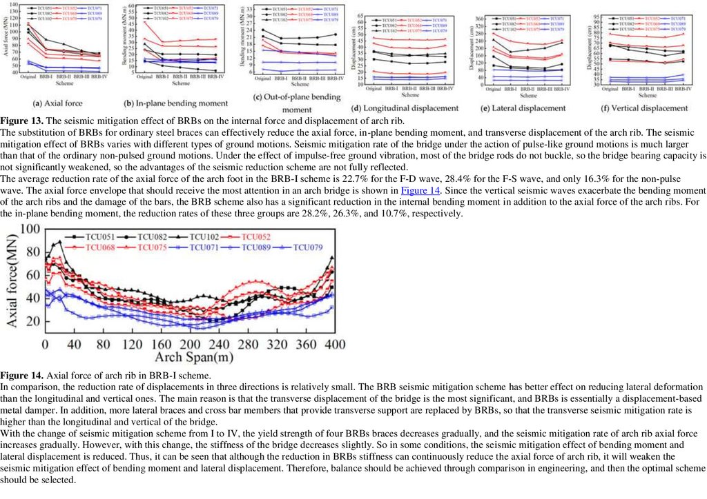
Результаты сравнения внутренней силы и ответов смещения главных секций первоначальной структуры и BRB сейсмической структуры уменьшения под тремягруппами движений основания(земли) показываются в Числе(фигуре) 13 < https: // www. mdpi. com/2075-5309/12/12/2147 > a-f.
Число(фигура) 13. Сейсмический результат(влияние) уменьшения BRBS на внутренней силе и смещении ребра арки(дуги).
Замена BRBS для обычных стальных фигурных скобок может эффективно уменьшать осевую силу, " в самолете " изгибающийся момент, и поперечное смещение
ребра арки(дуги). Сейсмический результат(влияние) уменьшения BRBS изменяется с различными типами движений основания(земли). Сейсмическая
норма(разряд) уменьшения моста при действии пульс-подобных движений основания(земли) намного большая чем таковой обычного не - pulsed, основывают
движения. Под результатом(влиянием) свободной от импульса вибрации основания(земли), большинство прутов моста делает не застежку, так что мост, несущий
способность(вместимость) знаменательно не ослаблен, так что преимущества сейсмической схемы сокращения полностью не отражены.
Средняя норма(разряд) сокращения осевой силы фута(ноги) арки(дуги) в BRB-I схеме - 22.7 % для F-D волны, 28.4 % для F-S волны, и только 16.3 % для волны
не-пульса. Осевой конверт силы, который должен получить наиболее внимание в мосте арки(дуги), показывается в Числе(фигуре) 14 < https: // www. mdpi.
com/2075-5309/12/12/2147 >. Так как вертикальные сейсмические волны усиливают изгибающийся момент ребер арки(дуги) и повреждения(ущерба)
брусков(баров), BRB схема также имеет существенное сокращение внутреннего изгиба момент в дополнение к осевой силе ребер арки(дуги). Для " в самолете "
изгибающийся момент, нормы(разряды) сокращения из этих трех групп - 28.2 %, 26.3 %, и 10.7 %, соответственно.
Число(фигура) 14. Осевая сила ребра арки(дуги) в BRB-I схеме.
На сравнении, норма(разряд) сокращения смещений в трех руководствах(направлениях) относительно маленькая. BRB сейсмическая схема уменьшения имеет
лучше результат(влияние) на сокращение боковой деформации чем продольные и вертикальные. Главная причина - то, что поперечное смещение моста является
наиболее существенным, и BRBS - по существу смещение-основанный металлический увлажнитель. Кроме того, более боковые фигурные скобки и взаимные
члены бруска(бара), которые обеспечивают поперечную поддержку, заменены BRBS, так, чтобы поперечная сейсмическая норма(разряд) уменьшения была выше
чем продольный и вертикален из моста.
34.
С изменением(заменой) сейсмической схемы уменьшения от я до IV, сила урожая четыре BRBS фигурные скобки уменьшаю постепенно, и сейсмическаянорма(разряд) уменьшения ребра арки(дуги) осевые увеличения силы постепенно. Однако, с этим изменением(заменой), неподвижность моста уменьшается
слегка. Так в некоторых условиях(состояниях), сейсмический результат(влияние) уменьшения изгибающегося момента и бокового смещения уменьшен. Таким
образом, может быть замечено, что, хотя сокращение BRBS неподвижности может непрерывно уменьшать осевую силу ребра арки(дуги), это ослабит
сейсмический результат(влияние) уменьшения изгибающегося момента и бокового смещения. Поэтому, баланс должен быть достигнут через сравнение в
разработке, и затем оптимальная схема должна быть отобрана.
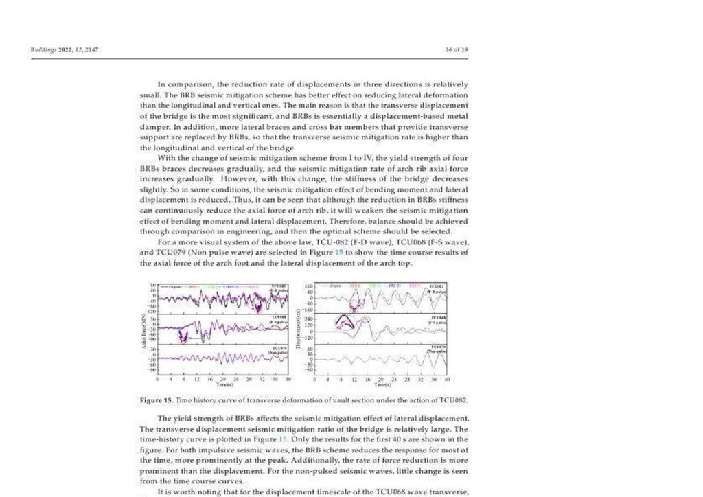
Для более визуальной системы вышеупомянутого закона, TCU-082 (F-D волна), TCU068 (F-S волна), и TCU079 (Не волна пульса) отобрана в Числе(фигуре) 15 <
https: // www. mdpi. com/2075-5309/12/12/2147 >, чтобы показать результаты курса времени осевой силы фута(ноги) арки(дуги) и бокового смещения вершины
арки(дуги).
Число(фигура) 15. Кривая истории Времени поперечной деформации секции хранилища при действии TCU082.
Сила урожая BRBS воздействует на сейсмический результат(влияние) уменьшения бокового смещения. Поперечное смещение сейсмическое отношение
уменьшения моста относительно большое. Кривая истории времени подготовлена в Числе(фигуре) 15 < https: // www. mdpi. com/2075-5309/12/12/2147 >. Только
результаты для первый 40 s показываются в числе(фигуре). Для оба impulsive сейсмические волны, BRB схема уменьшает ответ в течение большинства времени,
более заметно в пике. Дополнительно, норма(разряд) сокращения силы более видна чем смещение. Для не - pulsed сейсмические волны, немного
изменения(замены) замечены от кривых курса времени.
Это стоит отмечать, что для смещения timescale TCU068 поперечной волны, пиковое смещение BRB-IV схемы - 20.3 % больше чем таковой BRB-III схемы в 15.32
s. В то же самое время, норма(разряд) сокращения других BRB схем сил колеблется не больше, чем 6.3 %, сравненный с BRB-I схемой. Поэтому, при должным
образом ослаблении неподвижности BRBS может уменьшать сейсмический ответ внутренней силы моста, это будет неблагоприятно ответу смещения, если
неподвижность BRBS слишком маленькая. На основе обеспечения упругой и окончательной стабильности структуры под маленькими землетрясениями,
проектировщик должен соответственно уменьшить силу урожая BRBS около секции с маленьким смещением и увеличивать силу урожая около секции с большим
смещением. Таким образом, область гистерезисной петли может быть увеличена, который является выгодным, чтобы улучшить полную сейсмическую
эффективность уменьшения структуры.
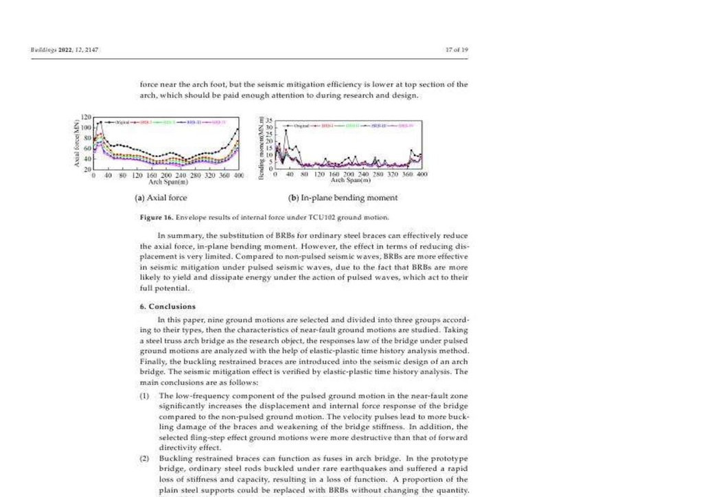
В дополнение к областям предприятия(беспокойства), внесенного в список выше, результаты конверта ребра арки(дуги) осевые силы и " в самолете "
изгибающиеся моменты рассчитаны, чтобы визуализировать изменения(разновидности) силы всех ребер арки(дуги) в BRB схеме. При взятии TCU102 как пример,
Фигурируйте 16 < https: // www. mdpi. com/2075-5309/12/12/2147 > a, b показывает ребру арки(дуги) осевые результаты конверта силы оригинала и BRB
сейсмической структуры уменьшения. BRB сейсмическая структура уменьшения имеет самую высокую сейсмическую норму(разряд) уменьшения для осевой
силы около фута(ноги) арки(дуги), но сейсмическая эффективность уменьшения более низкая в высшей секции арки(дуги), которая должна быть оплачена
достаточно внимания к в течение исследования и проекта.
35.
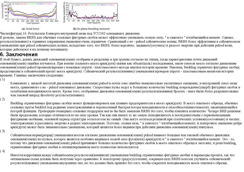
Число(фигура) 16. Результаты Конверта внутренней силы под TCU102 основывают движение.В резюме, замена BRBS для обычных стальных фигурных скобок может эффективно уменьшать осевую силу, " в самолете " изгибающийся момент. Однако,
результат(влияние) в терминах сокращения смещения очень ограничен. Сравненный с не - pulsed сейсмические волны, BRBS более эффективны в сейсмическом
уменьшении при pulsed сейсмических волнах, вследствие того, что BRBS, более вероятно, выдавать(уступать) и рассеет энергию при действии pulsed волн,
которые действуют к их полному потенциалу.
6. Заключения
В этой бумаге, девять движений основания(земли) отобраны и разделены в три группы согласно их типам, тогда характеристики почти движений
основания(земли) ошибки изучаются. При взятии стального моста арки(дуги) связки как объект(цель) исследования, закон ответов моста согласно движениям
основания(земли) pulsed проанализирован с помощью упруги - пластмассового метода анализа истории времени. Наконец, buckling ограничил фигурные скобки,
представлены в сейсмический проект моста арки(дуги). Сейсмический результат(влияние) уменьшения проверен упруги - пластмассовым анализом истории
времени. Главные заключения следующие:
( 1)
Компонент с низкой частотой движения основания(земли) pulsed в почти зоне ошибки знаменательно увеличивает смещение, и внутренний ответ силы
моста, сравненного с не - pulsed основывает движение. Скоростные пульс ведут к большему количеству buckling повреждение(ущерб) фигурных скобок и
ослабления неподвижности моста. Кроме того, отобранные движения основания(земли) результата(влияния) бросать - шага были более разрушительные
чем таковой вперед directivity результат(влияние).
( 2)
Buckling ограниченные фигурные скобки может функционировать как плавкие предохранители в мосте арки(дуги). В мосте опытного образца, обычные
стальные пруты buckled под редкими землетрясениями и перенесенный быстрая потеря неподвижности и способности(вместимости), заканчивающейся
потерей функции. Пропорция очевидных стальных поддержек могла бы быть заменена BRBS без того, чтобы изменить количество. Четыре BRB решения
были предложены, которые отличаются по их силе урожая. Так как они имеют ту же самую неподвижность и последовательны с первоначальными
фигурными скобками, основной период структуры остается тем же самый. Они могут остаться резинкой при статических условиях(состояниях) и частых
землетрясениях и рассеивать энергию в редких землетрясениях. Поэтому, осевая сила, " в самолете " изгибающийся момент, и поперечное смещение ребра
арки(дуги) может быть знаменательно уменьшена, который является более видным при действии движения основания(земли) импульса.
( 3)
Сейсмическая норма(разряд) уменьшения мостов согласно движениям основания(земли) pulsed намного большая чем таковой обычного движения
основания(земли) не-пульса, которое является особенно видным в осевой силе фута(ноги) арки(дуги) и " в самолете " изгибающийся момент. Это - то,
потому что движения основания(земли) pulsed причиняют большее количество фигурных скобок в мосте опытного образца к застежке, и роли buckling,
ограниченные фигурные скобки в оптимизированном мосте полностью используются.
( 4)
Имеется корреляция между сейсмическим результатом(влиянием) уменьшения buckling ограниченные фигурные скобки и параметры проекта, так что
оптимальная схема должна быть получена через сравнение. К некоторому градусу(степени), сокращая силу BRBS полезен улучшить сейсмический
результат(влияние) уменьшения внутренних сил, но это должно быть принято без того, чтобы сократить неподвижность моста опытного образца.
36.
Кроме того, должно быть отмечено, что сейсмический результат(влияние) уменьшения BRB сейсмической схемы уменьшения близко связан с параметрами, типасилы урожая, расположения, и характеристик движения основания(земли). Далее исследование необходимо установить BRBS различных спецификаций около
частей с различными градусами(степенями) деформации и выдви& оптимальную сейсмическую схему уменьшения.
Вклады Автора
Осмысление, H.G.; методология, H.G.; программное обеспечение, H.G. И K.Z.; validation, K.Z. И H.L.; формальный анализ, H.G.; исследование, H.L.; ресурсы, L.Z.;
данные curation, H.G.; пишущий - первоначальный проект подготовки, H.G.; пишущий - обзор и редактирование, K.Z., X.W., H.L. И L.Z.; визуализация, H.G.;
наблюдение, X.W. И L.Z.; проектная(строительная) администрация, L.Z.; финансирование(консолидирование) приобретения, H.L. И L.Z. Все авторы читали и
согласились на изданную версию рукописи.
Финансирование(консолидирование)
Это исследование было материально поддержано Национальным Ключом R$D Программа Китая (номер 2021YFB2600500(число) предоставления).
Установленное Утверждение(заявление) Наблюдательного совета
Не применимый.
Информированное Утверждение(заявление) Согласия
Не применимый.
Утверждение(заявление) Пригодности(готовности) Данных
Данные, представленные в этом изучении доступны по запросу от авторов.
Конфликты Интереса(процента)
Авторы не объявляют никакой конфликт интереса(процента).
Ссылки(рекомендации)
1.
FEER База данных. Доступный диалоговый: < https: // ngawest2. berkeley.edu > (обратился 1 июля 2013).
2.
Somerville, P.G.; Кузнец, Н.Ф.; Могилы, R.W.; Abrahamson, N.A. Модификация Эмпирических Сильных Отношений Ослабления Движения
Основания(земли), чтобы Включить Амплитуду и Результаты(влияния) Продолжительности Разрывает Directivity. Seismol. Res. Lett. 1997, 68, 199-222. [Google
Ученый < https: // ученый google.com/scholar_lookup? Право(название) = Модификация + + Эмпирический + Сильный + Основание(земля) + Движение +
Ослабление + Отношения + к + Включают + + Амплитуду + и + Продолжительность +, результаты(влияния) + + Разрывают + Directivity$author = Somerville, + P.
G. $author = Кузнеца, + N. F. $author = Могилы, + R. W. $author = Abrahamson, + N. $publication_year = 1997$journal = Seismol. + Res. + Lett. $volume = от 68$pages
до % 93222$doi % 80 199 % E2 = 10. 1785/gssrl.68.1.199 >] [CrossRef < https: // doi. org/10. 1785/gssrl.68.1.199 >]
3.
Wu, G.; Zhai, C.; Li, S.; Xie, L. Результатов(влияний) почти ошибки основывают движения и эквивалентные пульс на Большой Системе Линии башни
Передачи Пересечения(кроссирования). Eng. Struct. 2014, 77, 161-169. [Google Ученый < https: // ученый google.com/scholar_lookup? Право(название) =
Результаты(влияния) + + почти ошибка + основывает + движения + и + эквивалент + пульс + на + Большой + Пересекающий + Передача + Линия башни +
System$author = Wu, + G. $author = Zhai, + C. $author = Li, + S. $author = Xie, + L. $publication_year = 2014$journal = Eng. + Struct. $volume = от 77$pages до %
93169$doi % 80 161 % E2 = 10. 1016/j.engstruct.2014.08.013 >] [CrossRef < https: // doi. org/10. 1016/j.engstruct.2014.08.013 >]
4.
Yang, D.; Zhou, J. Стохастическая модель и синтез для почти ошибки impulsive основывает движения. Earthq. Eng. Struct. Dyn. 2015, 44, 243-264. [Google
Ученый < https: // ученый google.com/scholar_lookup? Право(название) = + стохастический + модель + и + синтез + для + почти ошибка + impulsive + основывает +
motions$author = Yang, + D. $author = Zhou, + J. $publication_year = 2015$journal = Earthq. + Eng. + Struct. + Dyn. $volume = от 44$pages до % 93264$doi % 80 243 %
E2 = 10. 1002/eqe.2468 >] [CrossRef < https: // doi. org/10. 1002/eqe.2468 >]
5.
Yan, G.; Chen, F. Сейсмическое Выполнение(работа) Midstory Изолировало Структуры согласно Почти Полевому Пульс-подобному Движению
Основания(земли) и Деформации Ограничения Слоев Изоляции. Удар Vib. 2015, 2015, 730612. [Google Ученый < https: // ученый google.com/scholar_lookup?
Право(название) = Сейсмический + Выполнение(работа) + + Midstory + Изолированный + Структуры + под + Почти Полевой + Пульс-подобный +
37.
Основание(земля) + Движение + и + Ограничивающий + Деформация + + Изоляция + Layers$author = Yan, + G. $author = Chen, + F. $publication_year =2015$journal = Удар + Vib. $volume = 2015$pages = от 730612$doi до 10.1155/2015/730612 >] [CrossRef < https: // doi. org/10. 1155/2015/730612 >]
6.
Chopra, A.K.; Chintanapakdee, C. Сравнение ответа SDF систем к почти ошибке и движениям землетрясения с далекой ошибкой в контексте спектральных
областей(регионов). Earthq. Eng. Struct. Dyn. 2001, 30, 1769-1789. [Google Ученый < https: // ученый google.com/scholar_lookup? Право(название) = Сравнение +
ответ + + SDF + системы + к + почти ошибка + и + далекая ошибка + землетрясение + движения + в + + контекст + + спектральный + regions$author = Chopra, +
k.$author = Chintanapakdee, + C. $publication_year = 2001$journal = Earthq. + Eng. + Struct. + Dyn. $volume = от 30$pages до % 931789$doi % 80 1769 % E2 = 10.
1002/eqe.92 >] [CrossRef < https: // doi. org/10. 1002/eqe.92 >]
7.
Mavroeidis, G.P.; Papageorgiou, A.S. Математическое представление почти ошибки основывает движения. Бык. Seismol. Soc.. 2003, 93, 1099-1131. [Google
Ученый < https: // ученый google.com/scholar_lookup? Право(название) = + математический + представление + + почти ошибка + основывает + motions$author =
Mavroeidis, + G. P. $author = Papageorgiou, + s.$publication_year = 2003$journal = Быка. + Seismol. + Soc. + $volume = от 93$pages до % % 80 1099 % E2 от
931131$doi до 10.1785/0120020100 >] [CrossRef < https: // doi. org/10. 1785/0120020100 >]
8.
Ghahari, S.F.; Jahankhah, H.; Ghannad, M.A. Изучение на упругом ответе структур к почти ошибке основывает движения через рекордное разложение. Почва
Dyn. Earthq. Eng. 2010, 30, 536-546. [Google Ученый < https: // ученый google.com/scholar_lookup? Право(название) = Изучение + на + резинка + ответ + +
структурирует + к + почти ошибку + основание(земля) + движения + через + отчет(рекорд) + decomposition$author = Ghahari, + S. F. $author = Jahankhah, + H.
$author = Ghannad, + М. a.$publication_year = 2010$journal = Почва + Dyn. + Earthq. + Eng. $volume = от 30$pages до % 93546$doi % 80 536 % E2 = 10.
1016/j.soildyn.2010.01.009 >] [CrossRef < https: // doi. org/10. 1016/j.soildyn.2010.01.009 >]
9.
Li, S.; Zhang, F.; Wang, J.-q.; Alam, M.S.; Zhang, J. Результаты(влияния) Почти Движений Ошибки и Искусственных Движений Основания(земли) Типа
пульса на Супер-промежутке Остающиеся телеграммой Системы Моста. J. Мост Eng. 2017, 22, 04016128. [Google Ученый < https: // ученый
google.com/scholar_lookup? Право(название) = Результаты(влияния) + + Почти Ошибка + Движения + и + Искусственный + Тип пульса + Основание(земля) +
Движения + на + Супер-промежуток + Остающийся телеграммой + Мост + Systems$author = Li, + S. $author = Zhang, + F. $author = Wang, + J. -q. $author = Alam, +
М. s.$author = Zhang, + J. $publication_year = 2017$journal = J. + Мост + Eng. $volume = 22$pages = от 04016128$doi до 10.1061 / (ASCE), быть] > [CrossRef < https: //
doi. org/10. 1061 / (ASCE), быть] >
10.
Billah, A.H.M.M.; Alam, M.S.; Bhuiyan, M.A.R. Анализ Недолговечности Retrofitted Моста Мультиколонки Согнулся Подвергнутый Почти Ошибке и
Далеко - полевому Движению Основания(земли). J. Мост Eng. 2013, 18, 992-1004. [Google Ученый < https: // ученый google.com/scholar_lookup? Право(название) =
Недолговечность + Анализ + + Retrofitted + Мультиколонка + Мост + Согнутый + Подвергнутый + к + Почти Ошибка + и + Далеко - полевой + Основание(земля)
+ Motion$author = Billah, + h.m.m.$author = Alam, + М. s.$author = Bhuiyan, + М. a.r.$publication_year = 2013$journal = J. + Мост + Eng. $volume = от 18$pages до %
% 80 992 % E2 от 931004$doi до 10.1061 / (ASCE), быть] > [CrossRef < https: // doi. org/10. 1061 / (ASCE), быть] >
11.
Davoodi, M.; Jafari, M.K.; Hadiani, N. Сейсмический ответ дамб набережной под почти ошибкой и далеко - полевым возбуждением движения
основания(земли). Eng. Geol. 2013, 158, 66-76. [Google Ученый < https: // ученый google.com/scholar_lookup? Право(название) = Сейсмический + ответ + +
набережная + дамбы + под + почти ошибка + и + далеко - полевой + основывает + движение + excitation$author = Davoodi, + М. $author = Jafari, + М. k.$author =
Hadiani, + N. $publication_year = 2013$journal = Eng. + Geol. $volume = от 158$pages до % 9376$doi % 80 66 % E2 = 10. 1016/j.enggeo.2013.02.008 >] [CrossRef <
https: // doi. org/10. 1016/j.enggeo.2013.02.008 >]
12.
Cui, Z.; Sheng, Q. Сейсмический ответ подземной пещеры скалы во власти большой геологической неоднородности, подвергнутой почти ошибке и далеко полевым движениям основания(земли). Подбородок. J. Скала Mech. Eng. 2017, 36, 53-67. [Google Ученый < https: // ученый google.com/scholar_lookup?
Право(название) = Сейсмический + ответ + + метрополитен(подполье) + качает + пещеру + доминир& + + + большой + геологический + неоднородность +
подвергнутый + к + почти ошибка + и + далеко - полевой + основание(земля) + motions$author = Cui, + Z. $author = Sheng, + Q. $publication_year = 2017$journal =
Подбородок. + J. + Скала + Mech. + Eng. $volume = от 36$pages до % 9367$doi % 80 53 % E2 = 10. 13722/j. cnki. jrme. 2016.0443 >] [CrossRef < https: // doi. org/10.
13722/j. cnki. jrme. 2016.0443 >]
13.
Losanno, D.; Hadad, H.A.; Serino, G. Сейсмическое поведение изолированных мостов с дополнительным демпфированием под далеко - полевым и около
ошибки основывает движение. Earthq. Struct. 2017, 13, 119-130. [Google Ученый < https: // ученый google.com/scholar_lookup? Право(название) = Сейсмический +
поведение + + изолированный + соединяет + с + дополнительный + заглушающий + под + далеко - полевой + и + около + ошибку + основание(земля) +
motion$author = Losanno, + D. $author = Hadad, + H. $author = Serino, + G. $publication_year = 2017$journal = Earthq. + Struct. $volume = от 13$pages до % 93130$doi
% 80 119 % E2 = 10. 12989/eas. 2017.13.2.119 >] [CrossRef < https: // doi. org/10. 12989/eas. 2017.13.2.119 >]
38.
14.Chen, X.; Li, J.; Guan, Z. Влияние Характеристик Движения Основания(земли) на Результатах(влияниях) С более высоким способом и Стратегии Проекта
для Высоких Мостов Пирса. J. Мост Eng. 2022, 28, 04022126. [Google Ученый < https: // ученый google.com/scholar_lookup? Право(название) = Влияние + +
Основание(земля) + Движение + Характеристики + на + Более высокий способ + Результаты(влияния) + и + Проект + Стратегия + для + Высокий + Пирс +
Bridges$author = Chen, + X. $author = Li, + J. $author = Guan, + Z. $publication_year = 2022$journal = J. + Мост + Eng. $volume = 28$pages = от 04022126$doi до
10.1061 / (ASCE), быть] > [CrossRef < https: // doi. org/10. 1061 / (ASCE), быть] >
15.
Yang, D.; Zhao, Y. Результаты(влияния) разрывают вперед directivity и бросают шаг почти движений основания(земли) ошибки на сейсмическом
выполнении(работе) изолированной основой структуры здания. Acta Seismol. Грех. 2010, 32, 579-587. [Google Ученый < https: // ученый google.com/scholar_lookup?
Право(название) = Результаты(влияния) + + разрывают + вперед + directivity +, и + бросают + шаг + + почти ошибка + основание(земля) + движения + на +
сейсмический + выполнение(работа) + + изолированный основой + строящий + structure$author = Yang, + D. $author = Zhao, + Y. $publication_year = 2010$journal =
Acta + Seismol. + Грех $volume = от 32$pages до % 93587$doi % 80 579 % E2 = 10. 3969/j.issn.0253-3782.2010.05.007 >] [CrossRef < https: //
doi.org/10.3969/j.issn.0253-3782.2010.0 5.007 >]
16.
Vui Фургон, C.; Ronagh, H.R. Корреляция между параметрами движений типа пульса и повреждения(ущерба) низкого повышения RC структуры(рамки).
Earthq. Struct. 2014, 7, 365-384. [Google Ученый < https: // ученый google.com/scholar_lookup? Право(название) = Корреляция + между + параметры + + тип пульса +
движения + и + повреждает + + низкое повышение + RC + frames$author = Vui + Фургон, + C. $author = Ronagh, + H. R. $publication_year = 2014$journal = Earthq. +
Struct. $volume = от 7$pages до % 93384$doi % 80 365 % E2 = 10. 12989/eas. 2014.7.3.365 >] [CrossRef < https: // doi. org/10. 12989/eas. 2014.7.3.365 >]
17.
Zaker Esteghamati, M.; Farzampour, A. Вероятностное сейсмическое выполнение(работа) и оценка потери многоэтажной стали, строящей оборудованный
плавкими предохранителями butterfly-форменный. J. Constr. Сталь Res. 2020, 172, 106187. [Google Ученый < https: // ученый google.com/scholar_lookup?
Право(название) = Вероятностный + сейсмический + выполнение(работа) + и + потеря + оценка + + + многоэтажный + сталь + строящий + оборудованный + с +
butterfly-форменный + fuses$author = Zaker + Esteghamati, + М. $author = Farzampour, + $publication_year = 2020$journal = J. + Constr. + Сталь + Res. $volume =
172$pages = 106187$doi = 10. 1016/j.jcsr.2020.106187 >] [CrossRef < https: // doi. org/10. 1016/j.jcsr.2020.106187 >]
18.
Upadhyay, A.; Pantelides, C.P.; Ibarra, L. Остаточных уменьшения дрейфа для мостов retrofitted с buckling ограничило фигурные скобки или сам
сосредоточение устройств разложения энергии. Eng. Struct. 2019, 199, 109663. [Google Ученый < https: // ученый google.com/scholar_lookup? Право(название) =
Остаточный + дрейфует + уменьшение + для + мосты + retrofitted + с + buckling + ограниченный + фигурные скобки + или + сам + сосредотачивающий + энергия +
разложение + devices$author = Upadhyay, + $author = Pantelides, + C. P. $author = Ibarra, + L. $publication_year = 2019$journal = Eng. + Struct. $volume = 199$pages =
109663$doi = 10. 1016/j.engstruct.2019.109663 >] [CrossRef < https: // doi. org/10. 1016/j.engstruct.2019.109663 >]
19.
Adanur, S.; Altuni? Ik, A.C.; Bayraktar, A.; Akk? Se, М. Сравнение почти ошибки и далекой ошибки основывает результаты(влияния) движения на
geometrically нелинейное поведение землетрясения висячих мостов. Nat. Опасности 2012, 64, 593-614. [Google Ученый < https: // ученый
google.com/scholar_lookup? Право(название) = Сравнение + + почти ошибка + и + далекая ошибка + основывает + движение + результаты(влияния) + на +
geometrically + нелинейный + землетрясение + поведение + + приостановка + bridges$author = Adanur, + S. $author = Altuni % 9Fik % C5, + c.$author = Bayraktar, +
$author = Akk % B6se % C3, + М. $publication_year = 2012$journal = Nat. + Hazards$volume = от 64$pages до % 93614$doi % 80 593 % E2 = 10. 1007/s11069-0120259-5 >] [CrossRef < https: // doi. org/10. 1007/s11069-012-0259-5 >]
20.
Shrestha, B. Сейсмический ответ длинного промежутка остающийся телеграммой мост к почти ошибке вертикальные движения основания(земли). KSCE J.
Civ. Eng. 2015, 19, 180-187. [Google Ученый < https: // ученый google.com/scholar_lookup? Право(название) = Сейсмический + ответ + + долго + охватывает +
остающийся телеграммой + мост + к + почти ошибка + вертикальный + основание(земля) + motions$author = Shrestha, + B. $publication_year = 2015$journal = KSCE
+ J. + Civ. + Eng. $volume = от 19$pages до % 93187$doi % 80 180 % E2 = 10. 1007/s12205-014-0214-y >] [CrossRef < https: // doi. org/10. 1007/s12205-014-0214-y >]
21.
Lu, Z.H.; Usami, T.; Ge, H.B. Сейсмическая оценка выполнения(работы) стальной арки(дуги) соединяет против главных землетрясений. Часть 2:
Упрощенная процедура проверки. Earthq. Eng. Struct. Dyn. 2004, 33, 1355-1372. [Google Ученый < https: // ученый google.com/scholar_lookup? Право(название) =
Сейсмический + выполнение(работа) + оценка + + сталь + арка(дуга) + соединяет + против + главный + землетрясения. + Часть + 2: + Упрощенный + проверка +
procedure$author = Lu, + Z. H. $author = Usami, + T. $author = Ge, + H. B. $publication_year = 2004$journal = Earthq. + Eng. + Struct. + Dyn. $volume = от 33$pages до
% 931372$doi % 80 1355 % E2 = 10. 1002/eqe.406 >] [CrossRef < https: // doi. org/10. 1002/eqe.406 >]
22.
Bai, F.-L.; Hao, H.; Li, H.-N. Сейсмический Ответ Стали Trussed Структура Арки(дуги) к Пространственно Изменяющимся Движениям Основания(земли)
Землетрясения, включая Результат(влияние) Участка. Реклама. Struct. Eng. 2010, 13, 1089-1103. [Google Ученый < https: // ученый google.com/scholar_lookup?
Право(название) = Сейсмический + Ответ + + + Сталь + Trussed + Арка(дуга) + Структура + к + Пространственно + Изменяющий + Землетрясение +
39.
Основание(земля) + Движения +, включая + Участок + Effect$author = Bai, + F. -l. $author = Hao, + H. $author = Li, + H. -n. $publication_year = 2010$journal =Реклама. + Struct. + Eng. $volume = от 13$pages до % % 80 1089 % E2 от 931103$doi до 10.1260/1369-4332.13.6.1089 >] [CrossRef < https: // doi. org/10. 1260/13694332.13.6.1089 >]
23.
Alvarez, J.J.; Aparicio, A.C.; Jara, J.M.; Jara, М. Сейсмическая оценка моста арки(дуги) с длинным промежутком, рассматривающего
изменение(разновидность) в осевых силах, вынужденных(вызванных) землетрясениями. Eng. Struct. 2012, 34, 69-80. [Google Ученый < https: // ученый
google.com/scholar_lookup? Право(название) = Сейсмический + оценка + + + длинный промежуток + арка(дуга) + соединяет + рассмотрение + +
изменение(разновидность) + в + осевой + силы + вынужденный(вызванный) + + earthquakes$author = Alvarez, + J. J. $author = Aparicio, + c.$author = Jara, + J. М.
$author = Jara, + М. $publication_year = 2012$journal = Eng. + Struct. $volume = от 34$pages до % 9380$doi % 80 69 % E2 = 10. 1016/j.engstruct.2011.09.013 >]
[CrossRef < https: // doi. org/10. 1016/j.engstruct.2011.09.013 >]
24.
Li, R.; Ge, H.; Maruyama, R. Оценка эксплуатационной надежности пост-землетрясения для стальной арки(дуги) соединяет с сейсмическими
увлажнителями, рассматривающими последовательности mainshock-толчка. Earthq. Struct. 2017, 13, 137-150. [Google Ученый < https: // ученый
google.com/scholar_lookup? Право(название) = Оценка + + пост-землетрясение + эксплуатационная надежность + для + сталь + арка(дуга) + соединяет + с +
сейсмический + увлажнители + рассмотрение + mainshock-толчок + sequences$author = Li, + R. $author = Ge, + H. $author = Maruyama, + R. $publication_year =
2017$journal = Earthq. + Struct. $volume = от 13$pages до % 93150$doi % 80 137 % E2 = 10. 12989/eas. 2017.13.2.137 >] [CrossRef < https: // doi. org/10. 12989/eas.
2017.13.2.137 >]
25.
Bazaez, R.; Dusicka, P. Циклическая погрузка для RC соединяет колонки, рассматривающие subduction землетрясения мегатолчка. J. Мост Eng. 2016, 21,
04016009. [Google Ученый < https: // ученый google.com/scholar_lookup? Право(название) = Циклический + загружающий + для + RC + соединяет + колонки +
рассмотрение + subduction + мегатолчок + earthquakes$author = Bazaez, + R. $author = Dusicka, + P. $publication_year = 2016$journal = J. + Мост + Eng. $volume =
21$pages = от 04016009$doi до 10.1061 / (ASCE) Быть] > [CrossRef < https: // doi. org/10. 1061 / (ASCE) Быть] >
26.
Chen, X.; Ikago, K.; Guan, Z.; Li, J.; Wang, X. " ведущее отношение(поведение) каучука " с отрицательной неподвижностью вес& (LRB-NS) для изоляции
основы сейсмический проект эластичных мостов: теоретическое технико-экономическое обоснование. Eng. Struct. 2022, 266, 114601. [Google Ученый < https: //
ученый google.com/scholar_lookup? Право(название) = " ведет отношение(поведение) каучука " + с + отрицательный + неподвижность + вес& + (LRB-NS) + для +
изоляция основы + сейсмический + проект + + эластичный + мосты: + + теоретический + выполнимость + study$author = Chen, + X. $author = Ikago, + K. $author =
Guan, + Z. $author = Li, + J. $author = Wang, + X. $publication_year = 2022$journal = Eng. + Struct. $volume = 266$pages = 114601$doi = 10.
1016/j.engstruct.2022.114601 >] [CrossRef < https: // doi. org/10. 1016/j.engstruct.2022.114601 >]
27.
Chen, X.; Xiang, N.; Guan, Z.; Li, J. Сейсмическая оценка уязвимости высокого пирса соединяет под mainshock-aftershock-like последовательностями
землетрясения, использующими оцененную вектором меру интенсивности. Eng. Struct. 2022, 253, 113732. [Google Ученый < https: // ученый
google.com/scholar_lookup? Право(название) = Сейсмический + уязвимость + оценка + + высокий + пирс + соединяет + под + mainshock-aftershock-like +
землетрясение + последовательности + использование + оцененный вектором + интенсивность + measure$author = Chen, + X. $author = Xiang, + N. $author = Guan,
+ Z. $author = Li, + J. $publication_year = 2022$journal = Eng. + Struct. $volume = 253$pages = 113732$doi = 10. 1016/j.engstruct.2021.113732 >] [CrossRef < https: //
doi. org/10. 1016/j.engstruct.2021.113732 >]
28.
Chen, X.; Xiong, J. Сейсмический эластичный проект с устройством изоляции основы, использующим отношение(поведение) маятника трения и вязкий
увлажнитель. Почва Dyn. Earthq. Eng. 2022, 153, 107073. [Google Ученый < https: // ученый google.com/scholar_lookup? Право(название) = Сейсмический +
эластичный + проектирует + с + основу + изоляция + устройство + использование + трение + маятник + несущий + и + вязкий + damper$author = Chen, + X. $author
= Xiong, + J. $publication_year = 2022$journal = Почва + Dyn. + Earthq. + Eng. $volume = 153$pages = 107073$doi = 10. 1016/j.soildyn.2021.107073 >] [CrossRef <
https: // doi. org/10. 1016/j.soildyn.2021.107073 >]
29.
Alam, M.S.; Bhuiyan, M.A.R.; Billah, A.H.M.M. Сейсмическая оценка недолговечности SMA-БРУСКА ограниченный много-промежуток непрерывный мост
шоссе, изолированный различными слоистыми резиновыми отношениями(поведениями) в среде к сильным сейсмическим зонам риска. Бык. Earthq. Eng. 2012, 10,
1885-1909. [Google Ученый < https: // ученый google.com/scholar_lookup? Право(название) = Сейсмический + недолговечность + оценка + + SMA-БРУСОК +
ограниченный + много-охватывает + непрерывный + шоссе + мост + изолированный + + различный + слоистый + каучук + отношения(поведения) + в + среда + к +
сильный + сейсмический + риск + zones$author = Alam, + М. s.$author = Bhuiyan, + М. a.r.$author = Billah, + h.m.m.$publication_year = 2012$journal = Бык. + Earthq.
+ Eng. $volume = от 10$pages до % 931909$doi % 80 1885 % E2 = 10. 1007/s10518-012-9381-8 >] [CrossRef < https: // doi. org/10. 1007/s10518-012-9381-8 >]
40.
30.Dezfuli, F.H.; Alam, M.S. Выполнение-основанная оценка и проект FRP-ОСНОВАННОГО высокого каучука демпфирования отношение(поведение)
включенного с проводами сплава памяти формы. Eng. Struct. 2014, 61, 166-183. [Google Ученый < https: // ученый google.com/scholar_lookup? Право(название) =
Выполнение-основанный + оценка + и + проектирует + + FRP-ОСНОВАННЫЙ + высоко + заглушающий + каучук + несущий + включенный + с + форма + память
+ сплав + wires$author = Dezfuli, + F. H. $author = Alam, + М. s.$publication_year = 2014$journal = Eng. + Struct. $volume = от 61$pages до % 93183$doi % 80 166 %
E2 = 10. 1016/j.engstruct.2014.01.008 >] [CrossRef < https: // doi. org/10. 1016/j.engstruct.2014.01.008 >]
31.
Kim, J.K.; Choi, H.H. Поведение и проект структур с buckling-ограниченными фигурными скобками. Eng. Struct. 2004, 26, 693-706. [Google Ученый < https:
// ученый google.com/scholar_lookup? Право(название) = Поведение + и + проектирует + + структуры + с + buckling-ограничиваемый + braces$author = Kim, + J. K.
$author = Choi, + H. H. $publication_year = 2004$journal = Eng. + Struct. $volume = от 26$pages до % 93706$doi % 80 693 % E2 = 10. 1016/j.engstruct.2003.09.010 >]
[CrossRef < https: // doi. org/10. 1016/j.engstruct.2003.09.010 >]
32.
Hoveidae, N.; Rafezy, B. Полное buckling поведение все-стали buckling ограниченные фигурные скобки. J. Constr. Сталь Res. 2012, 79, 151-158. [Google
Ученый < https: // ученый google.com/scholar_lookup? Право(название) = Полный + buckling + поведение + + все-сталь + buckling + ограниченный + braces$author =
Hoveidae, + N. $author = Rafezy, + B. $publication_year = 2012$journal = J. + Constr. + Сталь + Res. $volume = от 79$pages до % 93158$doi % 80 151 % E2 = 10.
1016/j.jcsr.2012.07.022 >] [CrossRef < https: // doi. org/10. 1016/j.jcsr.2012.07.022 >]
33.
Li, L.; Zhou, T.H.; Chen, J.W.; Chen, J.F. Новая Buckling-ограниченная Фигурная скобка с Переменным Ядром С взаимной секцией. Реклама. Civ. Eng. 2019,
2019, 4620430. [Google Ученый < https: // ученый google.com/scholar_lookup? Право(название) = + Новый + Buckling-ограничил + Фигурная скобка + с + +
Переменная + Взаимная секция + Core$author = Li, + L. $author = Zhou, + T. H. $author = Chen, + J. W. $author = Chen, + J. F. $publication_year = 2019$journal =
Реклама. + Civ. + Eng. $volume = 2019$pages = от 4620430$doi до 10.1155/2019/4620430 >] [CrossRef < https: // doi. org/10. 1155/2019/4620430 >]
34.
Xing, L.L.; Zhou, Y.; Huang, W. Сейсмический анализ оптимизации высотных зданий с buckling-ограниченной фигурной скобкой outrigger система. Eng.
Struct. 2020, 220, 110959. [Google Ученый < https: // ученый google.com/scholar_lookup? Право(название) = Сейсмический + оптимизация + анализ + + высотный +
здания + с + + buckling-ограничил + фигурная скобка + outrigger + system$author = Xing, + L. L. $author = Zhou, + Y. $author = Huang, + W. $publication_year =
2020$journal = Eng. + Struct. $volume = 220$pages = 110959$doi = 10. 1016/j.engstruct.2020.110959 >] [CrossRef < https: // doi. org/10. 1016/j.engstruct.2020.110959 >]
35.
Beiraghi, H.; Zhou, H. Двойное - стальная структура(рамка), состоящая из сопротивляющейся момента структуры(рамки) и фигурных скобок сплава памяти
формы, подвергнутых почти полевым землетрясениям. Struct. Des. Высокий Spec. Строить. 2020, 29, e1784. [Google Ученый < https: // ученый
google.com/scholar_lookup? Право(название) = Двойное - стальной + создает + состоящий + + сопротивляющийся момент + структуру(рамку) + и + форма + память
+ сплав + фигурные скобки + подвергнутый + к + почти полевой + earthquakes$author = Beiraghi, + H. $author = Zhou, + H. $publication_year = 2020$journal = Struct.
+ Des. + Высокий + Spec. + Строят $volume = 29$pages = e1784$doi = 10. 1002/tal.1784 >] [CrossRef < https: // doi. org/10. 1002/tal.1784 >]
36.
Wang, Y.; Ibarra, L.; Pantelides, C. Способность(вместимость) Краха железобетона искажала мосты retrofitted с buckling-ограниченными фигурными
скобками. Eng. Struct. 2019, 184, 99-114. [Google Ученый < https: // ученый google.com/scholar_lookup? Право(название) = Крах + способность(вместимость) + +
укрепленный + бетон + искаженный + соединяет + retrofitted + с + buckling-ограничиваемый + braces$author = Wang, + Y. $author = Ibarra, + L. $author = Pantelides,
+ C. $publication_year = 2019$journal = Eng. + Struct. $volume = от 184$pages до % 93114$doi % 80 99 % E2 = 10. 1016/j.engstruct.2019.01.033 >] [CrossRef < https: //
doi. org/10. 1016/j.engstruct.2019.01.033 >]
37.
Dong, H.H.; Du, X.L.; Han, Q.; Bi, K.M.; Hao, H. Гистерезисное выполнение(работа) RC пирса моста двойной колонка с само-сосредоточением bucklingограниченных фигурных скобок. Бык. Earthq. Eng. 2019, 17, 3255-3281. [Google Ученый < https: // ученый google.com/scholar_lookup? Право(название) =
Гистерезисный + выполнение(работа) + + RC + двойная колонка + соединяет + пирса + с + само-сосредотачивающий + buckling-ограничиваемый + braces$author =
Dong, + H. H. $author = Du, + X. L. $author = Han, + Q. $author = Bi, + K. М. $author = Hao, + H. $publication_year = 2019$journal = Бык. + Earthq. + Eng. $volume = от
17$pages до % 933281$doi % 80 3255 % E2 = 10. 1007/s10518-019-00586-4 >] [CrossRef < https: // doi. org/10. 1007/s10518-019-00586-4 >]
38.
Sosorburam, P.; Yamaguchi, E. Сейсмический Retrofit Стального Моста Связки, использующего Buckling Ограничил Увлажнитель. Appl. Sci. 2019, 9, 2791.
[Google Ученый < https: // ученый google.com/scholar_lookup? Право(название) = Сейсмический + Retrofit + + Сталь + Связка + Мост + Использование + Buckling +
Ограниченный + Damper$author = Sosorburam, + P. $author = Yamaguchi, + E. $publication_year = 2019$journal = Appl. + Sci. $volume = 9$pages = 2791$doi = 10.
3390/app9142791 >] [CrossRef < https: // doi. org/10. 3390/app9142791 >]
39.
Xiang, N.; Alam, M.S.; Li, J. Результат(влияние) Многоэтажного Распределения Фигурной скобки на Сейсмическом Выполнении(работе) RC Высокого
Моста Bents Retrofitted с Buckling Ограничил Фигурные скобки. J. Earthq. Eng. 2021, 26, 8688-8705. [Google Ученый < https: // ученый google.com/scholar_lookup?
Право(название) = Результат(влияние) + + Многоэтажный + Фигурная скобка + Распределение + на + Сейсмический + Выполнение(работа) + + RC + Высокий +
41.
Мост + Bents + Retrofitted + с + Buckling + Ограниченный + Braces$author = Xiang, + N. $author = Alam, + М. s.$author = Li, + J. $publication_year = 2021$journal = J.+ Earthq. + Eng. $volume = от 26$pages до % % 80 8688 % E2 от 938705$doi до 10.1080/13632469.2021.1991861 >] [CrossRef < https: // doi. org/10.
1080/13632469.2021.1991861 >]
40.
Celik, O.C.; Bruneau, М. Сейсмическое поведение bidirectional-стойкого податливого конца diaphragms с buckling ограничило фигурные скобки в прямых
стальных мостах. Eng. Struct. 2009, 31, 380-393. [Google Ученый < https: // ученый google.com/scholar_lookup? Право(название) = Сейсмический + поведение + +
bidirectional-стойкий + податливый + заканчивает + diaphragms + с + buckling + ограниченный + фигурные скобки + в + прямо + сталь + bridges$author = Celik, + O.
C. $author = Bruneau, + М. $publication_year = 2009$journal = Eng. + Struct. $volume = от 31$pages до % 93393$doi % 80 380 % E2 = 10. 1016/j.engstruct.2008.08.013
>] [CrossRef < https: // doi. org/10. 1016/j.engstruct.2008.08.013 >]
41.
Zaker Esteghamati, М. Целостный Обзор GM/IM Методов Выбора от Структурной Выполнение-основанной Перспективы. Sustainability 2022, 14, 12994.
[Google Ученый < https: // ученый google.com/scholar_lookup? Право(название) = + Целостный + Обзор + + GM/IM + Выбор + Методы + от + + Структурный +
Выполнение-основанный + Perspective$author = Zaker + Esteghamati, + М. $publication_year = 2022$journal = Sustainability$volume = 14$pages = 12994$doi = 10.
3390/su142012994 >] [CrossRef < https: // doi. org/10. 3390/su142012994 >]
42.
Carre? O, R.; Lotfizadeh, K.H.; Conte, J.P.; Restrepo, J.I. Материальные образцовые параметры для Giuffr? -Menegotto-Pinto uniaxial стальная модель
напряжения напряжения. J. Struct. Eng. 2020, 146, 04019205. [Google Ученый < https: // ученый google.com/scholar_lookup? Право(название) = Материал + модель +
параметры + для + + Giuffr % A8-Menegotto-Pinto % C3 + uniaxial + сталь + напряжение напряжения + model$author = Carre % B1o % C3, + R. $author = Lotfizadeh,
+ K. H. $author = Conte, + J. P. $author = Restrepo, + J. я $publication_year = 2020$journal = J. + Struct. + Eng. $volume = 146$pages = от 04019205$doi до 10.1061 /
(ASCE) ST. 1943-541X.0002505] > [CrossRef < https: // doi. org/10. 1061 / (ASCE) ST. 1943-541X.0002505] >
43.
JTG/T 2231-01; Спецификации для Сейсмического Проекта Мостов Шоссе. Министерство транспорта: Пекин, Китай, 2020.
44.
DBJ/CT105; Техническая Спецификация для TJ Buckling Ограниченные Фигурные скобки. Tongji Университет: Шанхай, Китай, 2011.
45.
Солнце, F.F.; Li, G.Q.; Guo, X.K.; Hu, D.Z.; Hu, B.L. Развитие нового типа buckling-ограничило фигурные скобки и их заявление(применение) в aseismic
стальных структурах. Реклама. Struct. Eng. 2011, 14, 717-730. [Google Ученый < https: // ученый google.com/scholar_lookup? Право(название) = Развитие + + новый
тип + buckling-ограничил + фигурные скобки + и + их + заявление(применение) + в + aseismic + сталь + frameworks$author = Солнце, + F. F. $author = Li, + G. Q.
$author = Guo, + X. K. $author = Hu, + D. Z. $author = Hu, + B. L. $publication_year = 2011$journal = Реклама. + Struct. + Eng. $volume = от 14$pages до % % 80 717 %
E2 от 93730$doi до 10.1260/1369-4332.14.4.717 >] [CrossRef < https: // doi. org/10. 1260/1369-4332.14.4.717 >]
Примечание Издателя: MDPI пребывание, нейтральные в отношении jurisdictional требует в изданных картах и установленных присоединении.
© 2022 авторами. Licensee MDPI, Базель, Швейцария. Эта статья(изделие) - открытая статья(изделие) доступа, распределенная согласно срокам(терминам) и
условиям(состояниям) Творческого Приписывания Палаты общин (CC) лицензия < (https: // creativecommons. org/licenses/by/4. 0 / >).
Доля и Цитирует
MDPI и ACS Стиль
Gao, H.; Zhang, K.; Wu, X.; Liu, H.; Zhang, L. Заявления(применения) BRB к Сейсмическому Уменьшению Стального Моста Арки(дуги) Связки, подвергнутого
Почти Движениям Основания(земли) Ошибки. Здания 2022, 12, 2147. Https: // doi. org/10. 3390/buildings12122147
AMA Стиль
Gao H, Zhang K, Wu X, Liu H, Zhang L. Заявления(применения) BRB к Сейсмическому Уменьшению Стального Моста Арки(дуги) Связки, подвергнутого Почти
Движениям Основания(земли) Ошибки. Здания. 2022; 12 (12):2147. Https: // doi. org/10. 3390/buildings12122147
Chicago/Turabian Стиль
Gao, Haoyuan, Kun Zhang, Xinyu Wu, Hongjiang Liu, и Lianzhen Zhang. 2022. " Заявление(применение) BRB к Сейсмическому Уменьшению Стального Моста
Арки(дуги) Связки, подвергнутого Почти Движениям Основания(земли) Ошибки " Здания 12, Номер 12: 2147. Https: // doi. org/10. 3390/buildings12122147
Найдите Другие Стили
Обратите внимание, что от первой проблемы(выпуска) 2016, этот журнал использует номера(числа) статьи(изделия) вместо номеров страниц. См. дальнейшие
детали здесь < https: // www. mdpi. com/about/announcements/784 >.
42.
Метрика Статьи(изделия)Цитаты
Никакие цитаты не были найдены для этой статьи(изделия), но Вы можете проверять на Google Ученом < https: // ученого google.com/scholar_lookup?
Право(название) = Заявление(применение) + + BRB + к + Сейсмический + Уменьшение + + Сталь + Связка + Арка(дуга) + Мост + Подвергнутый + к + Почти
Ошибка + Основание(земля) + Motions$volume = от 12$doi до 10.3390 % 2Fbuildings12122147$journal = Buildings$publication_year = 2022$author = Haoyuan +
Gao$author = Kun + Zhang$author = Xinyu + Wu$author = Hongjiang + Liu$author = Lianzhen + Zhang >
Статистика Доступа Статьи(изделия)
Доступ Статьи(изделия) statisticsArticle Views6. Dec7. Dec8. Dec9. Dec10. Dec11. Dec12. Dec13. Dec14. Dec15. Dec16. Dec17. Dec18. Dec19. Dec20. Dec21. Dec22.
Dec23. Dec24. Dec25. Dec26. Dec27. Dec28. Dec29. Dec30. Dec31. Dec1. Jan2. Jan3. Jan4. Jan5. Jan6. Jan7. Jan8. Jan9. Jan10. Jan11. Jan12. Jan13. Jan14. Jan15. Jan16.
Jan17. Jan18. Jan19. Jan20. Jan21. Jan22. Jan23. Jan24. Jan25. Jan0200400600
7. DecSum: 188Daily представления(виды): 51
Для большего количества информации относительно статистики журнала, щелкните здесь < https: // www.mdpi.com/journal/buildings/stats >.
Многократные запросы от того же самого адреса IP подсчитаны как одно представление(вид).
Здания < https: // www.mdpi.com/journal/buildings >, EISSN 2075-5309, Изданный MDPI
Application of BRB to Seismic Mitigation of Steel Truss Arch Bridge Subjected to
Near-Fault Ground Motions
by
1
Haoyuan Gao
,
43.
Kun Zhang2
3
,
Xinyu Wu
,
4,*
Hongjiang Liu
and
44.
Lianzhen Zhang5
1
College of Civil Engineering, Tongji University, Shanghai 200092, China
2
College of Engineering, University of Auckland, Auckland 1023, New Zealand
3
Shenyang Geotechnical Investigation & Surveying Research Institute Co., Ltd., Shenyang 110004, China
4
College of Civil, Environmental and Land Magement Engineering, Polytechnic University of Milan, 20133 Milan, Italy
5
College of Transportation Science and Engineering, Harbin Institute of Technology, Harbin 150096, China
*
Author to whom correspondence should be addressed.
Buildings 2022, 12(12), 2147; https://doi.org/10.3390/buildings12122147
Received: 16 October 2022 / Revised: 23 November 2022 / Accepted: 1 December 2022 / Published: 6 December 2022
(This article belongs to the Special Issue New Trends in Seismic Performance Evaluation)
Download
Browse Figures
Versions Notes
Abstract
In this paper, the seismic response of a steel truss arch bridge subjected to near-fault ground motions is studied. Then, the idea of applying buckling restrained braces (BRBs)
to a steel truss arch bridge in near-fault areas is proposed and validated. Firstly, the basic characteristics of near-fault ground motions are identified and distinguished.
Furthermore, the seismic response of a long span steel truss arch bridge in the near fault area is analyzed by elastic-plastic time analysis. Finally, the braces prone to buckling
failure are replaced by BRBs to reduce the seismic response of the arch rib through their energy dissipation properties. Four BRB schemes were proposed with different yield
strengths, but the same initial stiffness. The basic period of the structure remains the same. The results show that near-fault ground motion will not only obviously increase the
displacement and internal force response of the bridge, but also cause more braces to buckle. By replacing a portion of the normal bars with BRBs, the internal forces and
displacements of the arch ribs can be reduced to some extent, which is more prominent under the action of pulsed ground motion. There is a clear correlation between the
damping effect and the parameters of BRB, so an optimized solution should be obtained by comparison and calculation.
Keywords:
near-fault ground motion; forward-directivity effect; fling-step effect; steel truss arch bridge; buckling restrained brace
45.
Graphical Abstract1. Introduction
In the event of an earthquake, the ground motions in the areas within 20 km of the fault have a super destructive power. In recent years, some historical earthquakes have
broken out in some countries and regions, and some valuable ground motions have been recorded. These seismic data [1] provide conditions for structural engineers to carry
out seismic research.
Seismologists and engineers have analyzed the characteristics of near fault ground motions in some ways. Somerville et al. [2] have pointed out that pulse effects in near-fault
areas cause spatial variations in ground motion amplitude and duration. Their characteristics and mechanism have been elaborated by many studies (Wu et al. [3], Yang and
Zhou [4], Yan and Chen [5]). Because of the difference of fault rupture mechanism, pulse-like ground motions can be divided into forward-directivity pulses (F-D pulses) and
fling-step pulses (F-S pulses). The velocity time history of forward-directivity pulses usually contain double or multiple peaks. The ground motions with fling-step pulses
usually exhibit two important characteristics: single velocity pulse and permanent ground displacement, which may make the structure subject to large deformations and
internal forces. In terms of research methods, Chopra and Chintanapakdee [6] have extended well-known concepts of elastic and inelastic response spectra based on far-fault
motion to near-fault motion. Mavroeidis and Papageorgiou [7] have proposed a simple analytical model for the representation of pulse-like ground motions, which adequately
describes the impulsive character of near-fault ground motions both qualitatively and quantitatively. Ghahari et al. [8] have used the moving average filtering method with
appropriate cut-off frequency to decompose the near-fault ground motion into two components with different frequency contents. This method has been promoted in recent
years. On this basis, Li et al. [9] have proposed a recorded decomposition integration method to synthesize artificial pulse-like ground motion by combining high-frequency
background records with simple equivalent pulses.
Thus, scientists and engineers now have a mature understanding of the mechanism, characteristics, and research methods of near-fault earthquakes, but their impact on
structures needs more attention. Some researchers (Billah et al. [10], Davoodi et al. [11], Cui and Sheng [12], Losanno et al. [13]) have studied the seismic responses of
various structures, including frames, dams, underground structures, and bridges near faults. Some researchers have tried to find correlations between ground motion
parameters and structural responses but there have been no consistent consensus (Chen et al. [14]). The response spectrum is an important way to investigate the special
influence of near-fault ground motion on structures. Yang and Zhao [15] have studied the influence of near-fault ground motions with forward-directivity pulse and fling-step
pulse on the seismic performance of base-isolated buildings with lead rubber bearings. Through time history and damage analyses of a tested 3-storey reinforced concrete
frame under 204 near-fault pulse-type records, some researchers (Vui Van et al. [16], Zaker et al. [17], Upadhyay et al. [18]) found that velocity spectrum intensity is leading
parameter demonstrating the best correlation.
In addition to the above studies, the low-frequency pulse effects of near-fault seismic waves lead to the need for more attention to their effects on long-period structures.
Adanur et al. [19] have compared the effects of near-fault and far-fault ground motions on the geometrically non-linear seismic behavior of suspension bridges. Shrestha [20]
presented an analytical investigation on the effect of the near fault ground motions on a long span cable-stayed bridge considering the vertical ground motion. They found that
near-fault ground motions produce greater displacements and internal forces on suspension bridges and cable-stayed bridges compared to far-fault ground motions. However,
fewer studies have been conducted on the seismic response of near-fault arch bridges. The arch bridge has a large span and high material utilization rate, which is especially
suitable for solid rocks in mountainous and canyon areas near faults. So it is necessary to study the near fault seismic response of the arch bridge. Some researchers (Lu et al.
[21], Bai et al. [22], Alvarez et al. [23], R. Li et al. [24], Bazaez et al. [25]) studied the seismic response of arch bridges by means of pushover analysis or time-history
analysis, but have not fully considered the special destructiveness of near-fault ground motions to this flexible structure.
The seismic responses of the arch bridge in the near fault areas need further analysis, and the corresponding seismic mitigation methods are also worthy of attention. Chen et
al. [26,27,28] have pointed out that advanced seismic isolation devices and systems have been recognized as promising measures toward resilient design of bridge structures.
Some researchers (Alam et al. [29], Dezfuli and Alam [30], R. Li et al. [24]) have proposed seismic mitigation methods, such as rubber bearings, elastic-plastic steel dampers,
and shape memory alloys, but these devices are limited and uneconomical in arch bridges. Kim and Choi [31] have pointed that buckling-restrained braces (BRBs) can yield in
tension and compression, exhibit stable and predictable hysteretic behavior, provide significant energy dissipation capacity and ductility, and are an attractive alternative to
conventional steel braces. Some researchers (Hoveidae and Rafezy [32], Li et al. [33], Xing et al. [34]) have optimized its structure and applied it to buildings, obtaining good
seismic mitigation effect. Beiraghi and Zhou [35] have designed a braced frame consisting of steel buckling-restrained braces (BRB model), braces with shape memory alloy
(SMA model), or combination of BRB and SMA braces. It is worth mentioning that they have taken advantage of performance-based design concepts. Concentric braced
46.
frames have been combined with moment-resisting frame as a dual system subjected to near-field pulse-like and far-field ground motions (Wang et al. [36]). To date, BRBshave been used extensively in building structures, but are not as widely used or researched in bridge structures. Dong et al. [37] installed self-centering buckling-restrained
braces on the reinforced concrete double-column bridge piers. Experimental results have demonstrated the obvious advantages of SC-BRB in increasing the strength and
minimizing the residual deformation of the bridge column. Sosorburam and Yamaguchi [38] has conducted a parametric study on the seismic behavior of the truss bridge with
BRB by changing the length, the cross-sectional area, the location, and the inclination. Xiang et al. [39] investigated the effect of BRB distribution on the seismic performance
of retrofitted multi-story reinforced concrete high bridge piers. However, the application of BRB in a steel truss arch bridge is rare (Celik et al. [40]).
The objectives of this paper are to investigate special seismic response of long-period steel truss arch bridge and introduce BRBs into the vibration reduction in steel truss arch
bridge in near fault areas. Firstly, nine ground motions with different characteristics are selected from PEER database [1], and their differences are analyzed by response
spectrum. Subsequently, taking a steel truss arch bridge as the research object, the response law of the bridge under forward-directivity pulsed, fling-step pulsed, and nonpulsed motions is analyzed with an elastic-plastic time history analysis method. Finally, the seismic mitigation method of using BRB to replace buckling-prone components is
proposed and verified. The results show that the internal force and displacement of the arch ribs can be reduced by replacing a portion of the normal bars with BRBs, which is
more prominent under the action of pulsed ground motion.
2. Near-Fault Ground Motions
2.1. Selected Seismic Waves
The Chi-Chi earthquake in Taiwan in 1999 is a typical large earthquake near the fault. In this paper, nine ground motions of different types in this earthquake are taken from
the latest database of the PEER NGA-West 2. The selection principles of ground motion are as follows: (1) the fault is within 20 km; and (2) peak acceleration and velocity
are greater than 100 cm/s2 and 30 cm/s, respectively. The three groups of time-history of ground motion velocity with different characteristics are shown in Figure 1a–i. The
first group contains three seismic waves, TCU-051, TCU-082, and TCU-102, representing F-D effect seismic waves; the second group contains three seismic waves, TCU052, TCU-068, and TCU-075, representing F-S effect seismic waves; the third group contains three seismic waves, TCU-071, TCU-089, and TCU-079, representing non-pulse
effect seismic waves. The basic properties of the ground motions, such as the closest distance to fault rupture (Rrup), peak ground acceleration (PGA), peak ground velocity
(PGV), peak ground displacement (PGD), PGV/PGA, and pulse period (Tp) are listed in Table 1. PGV/PGA is usually taken as the pulse parameter in the study to
preliminarily judge the strength of the velocity pulse. According to the preliminary judgment, the pulse effect of the selected P-S motions is the strongest, followed by the P-D
motions. In contrast, the ordinary non pulse ground motion is gentle.
47.
Figure 1. Velocity time history curve of ground motions.Table 1. Characteristics of different types of ground motions.
2.2. Response Spectrum of Seismic Waves
From the above-ground motion parameters, it can be seen that there are obvious differences in the motion characteristics of three different types of ground motion (Zaker at el.
[41]). Therefore, further research is needed through response spectrum. The elastic response spectrum of linear elastic single-degree-of-freedom system with 5% damping ratio
under three groups of ground motion is calculated, respectively, and the average value of each group is taken. The calculation results are shown in Figure 2a–c.
Figure 2. The average response spectrum curves of three groups of ground motions.
Comparing the response spectrum curves, the differences between the three types of ground motions are obvious. In the short period, the spectral velocity of non-pulse ground
motion is the largest. In the middle period, the acceleration value of the ground motion with forward effect is the largest. In the long period, the acceleration value of ground
motion with lightning effect is the largest. As for velocity spectrum and displacement spectrum, the spectrum value of pulse ground motion is larger than that of non-pulse
48.
ground motion in a long period. In general, the low-frequency components of pulse ground motion are relatively rich, which should be paid attention to in the design of longperiod structures near faults.The peak accelerations of the nine primary seismic waves are adjusted with reference to the Chinese seismic code for bridges (Wu at el. [3]). The rare earthquakes in the
Chinese code are similar to ASCE maximum considered earthquakes. The studied bridge is in the octave zone, so the peak acceleration in rare earthquakes was adjusted to 400
cm/s2.
3. Bridge Prototype and Modelling
3.1. Case Study Bridge for System Response
The prototype bridge is a long-span steel truss arch bridge spanning a valley in a near-fault area. Its net span is 400 m, the vector span ratio is 1/5, and the arch axis is ducted.
The main arch rib adopts steel truss structure, and the beam body is composed of steel and concrete. The height of the steel truss is 10 m, and the spacing of the three
transverse arch ribs is 10 m. The arch rib adopts a steel box structure with equal section, with a height of 1.5 m and a width of 1.0 m. The columns on the arch ribs are steelbending structures, and the three transverse columns are equal-section steel boxes. Stiffening ribs and transverse spacers are provided along the height of the columns. The
columns are supported by steel bars in the transverse direction to improve stability and safety. The layout of the bridge is shown in Figure 3. Critical details and parameters are
shown in Table 2. The brace members are made from Q345qD steel, with a nominal yield strength of 345 MPa. The elastic modulus, Poisson’s ratio, density of structural
member are listed in Table 3.
Figure 3. General layout of bridge. (unit: cm).
Table 2. Section of members.
49.
Table 3. Material parameters.3.2. Finite Element Model
The finite element model of the bridge is established by means of the finite element software Midas Civil, as shown in Figure 4. The quality, stiffness, and boundary
conditions directly determine the accuracy of the finite element analysis results. The arch ribs are simulated by the beam element, and the material model is a Menegotto–Pinto
theoretical model (Carreño at el. [42]). To account for non-linearity, lateral braces, vertical bars, cross bars, and braces of columns are embodied by the elasto-plastic hinge
element, and the material is simulated by a steel buckling model. The superstructure of the bridge was assumed to be elastic and was modeled by an elastic beam-column
element with a modulus of elasticity of 3.45 × 10⁴ Mpa. A non-linear beam-column fiber element was adopted to model the non-linear behavior of the columns. The
Concrete01 material model, which was developed based on the uniaxial Kent–Scott–Park model, was used for the concrete of the columns, with compressive strengths of 26.8
and 32.8 MPa for the unconfined and confined concrete, respectively. The reinforcing steel was modeled with uniaxial bilinear steel material of Steel01. The yield strength,
elastic modulus and strain-hardening ratio were assumed to be 400 MPa, 200 GPa and 0.02, respectively.
Figure 4. Finite element model of bridge.
In terms of boundary conditions, the support between the cover beam and the main beam is simulated with fixed support. At the end of the beam, movable supports are used to
simulate the longitudinal constraints of the bridge. The bearing is a basin type rubber bearing, whose construction and model are drawn in Figure 5. The fixed direction of the
bearing is restricted and the movable direction is represented by the bilinear model in Figure 5. The sliding displacement xy is 2 mm.
50.
Figure 5. Composition and model of bearing.4. Bridge Response
The analysis of the dynamic characteristics shows that the first three order periods of the bridge are 1.651 s, 0.921 s, and 0.745 s in the longitudinal direction; 3.927 s, 1.612 s,
and 0.809 s in the transverse direction; and 0.973 s, 0.741 s, and 0.577 s in the vertical direction. Elastoplastic time history analysis is used to simulate the seismic response of
bridges under rare earthquakes. Assume that the bridge is perpendicular to the fault. The seismic waves with the same name are input in the longitudinal, lateral, and vertical
directions of the bridge. The difference is that the PGA of the horizontal seismic wave is 400 cm/s2, while the vertical one is 2/3 of the horizontal one, which is determined by
referring to the Chinese code [43]. In Figure 6, the results for the nine working conditions are listed and each seismic wave represents one working condition. The three
conditions, TCU-051, TCU-082, and TCU-102, represent the bridge response under the F-D effect seismic waves, TCU-052, TCU-068, and TCU-075 represent the bridge
response under the F-S effect seismic waves, and TCU-071, TCU-089, and TCU-079 represent the bridge response under the non-pulsed effect seismic waves. According to
the internal force and displacement of key parts, such as arch foot, arch bottom, and 1/4 arch section, and the buckling of lateral braces, vertical bars, cross bars and braces of
columns, the response law of the bridge is summarized.
51.
Figure 6. Envelope results of arch rib response.4.1. Response of Arch Ribs
Under the action of three different types of ground motions, the envelope results of the internal force response of the arch ribs are shown in Figure 6a–c. The arch bridge span
is 400 m, the horizontal coordinates of the graph are the positions of the arch ribs in the axial direction of the bridge and the vertical coordinates are the results of the various
seismic responses. Figure 6 shows the envelope results for the axial forces of the arch ribs at each section. Figure 6b shows the results for in-plane bending moments and
Figure 6c shows the results for out-of-plane bending moments. Under various cases, the maximum axial force of the arch rib occurs in the arch foot section, and the bending
moment of the arch foot section is also much greater than that of the arch top and 1/4 arch section. The in-plane bending moment envelopment diagram is not smooth and
appears zigzag fluctuation, which is mainly caused by the force change of the upper column directly connected to the arch ribs.
Compared with non-pulsed ground motions, the internal force of key sections of arch rib is obviously greater under pulsed ground motion. For example, the mean value of
peak axial force of the arch foot under the action of three non-pulsed ground motions is 55,150.9 kN. The mean value under the action of F-D pulsed ground motions is
104,641.9 kN, and that under the action of F-S pulsed ground motions is 94,825.7 kN, which are increased by 89.7% and 71.9%, respectively, compared with the non-pulsed
effect. For arch ribs at different positions, the influence of pulse effect is also different. The pulsed ground motion has the greatest influence on the peak moment of arch foot
surface. Compared with non-pulsed ground motion, the increase rates of F-D effect and F-S effect pulse are 207% and 141.2%, respectively. Pulsed ground motions have the
least influence on the axial force of the vault, and the increase rates of forward-direction pulse and fling-step pulse are only 10.5% and 7.6%, respectively.
In terms of deformation, the distribution of longitudinal and vertical deformation is similar. Figure 6d–f show the results of the displacement envelope of the arch rib section
relative to the ground in the longitudinal, transverse, and vertical directions, respectively. The maximum displacement occurs near 1/4 arch section, while the peak value of
lateral displacement occurs near the vault. The displacement responses in all directions under the two kinds of pulsed ground motions are much greater than those of nonpulsed ground motions. On the one hand, it is because that the time-domain energy of pulse type ground motion is concentrated and the low-frequency pulse component is
52.
rich, which makes it easier to excite the basic mode of arch bridge with long-period. On the other hand, compared with the ordinary ground motions, the internal forceresponse of the component increases because of the huge velocity pulse. Thus, the braces near the arch foot are more prone to buckling failure, which reduces the overall
stiffness of the structure, and then leads to the increase in displacements.
The influence of the P-S effect on displacement is greater than the F-D effect. The slip effect seismic wave chosen for the study has a larger impulse period than that of the
directional effect seismic wave and is closer to the fundamental period of the steel truss arch bridge. Therefore, the displacement response is greater.
In general, long-period steel arch bridges are more susceptible to the low-frequency impulsive component of near-fault ground vibrations. Therefore, the seismic response of
steel truss arch bridges under impulsive seismic action is much larger than that of non-impulsive ones.
4.2. Buckling of Braces
Under the action of rare ground motion, the various supports of the bridge will buckle to varying degrees. The number of buckling braces under pulse ground motion is much
higher than that under non-pulse ground motion, as shown in Table 4.
Table 4. The number of buckling of braces under rare ground motions.
Due to complex forces near the arch foot, the number and degree of buckling of all kinds of braces near the arch foot are the largest in each working condition. A small part of
lateral braces near the 1/4 arch and the arch roof also suffer from buckling failure. Under the two kinds of pulsed ground motions, the braces buckle in different degrees, but it
keeps elastic under three non-pulsed ground motions. Figure 7a–i show the state of the bridge braces under the action of nine seismic waves. Braces in green represent no
buckling damage and braces in red represent buckling damage. In general, the number of buckling braces is proportional to the transverse displacement of the arch rib. The
greater the lateral displacement is, the more likely the braces are to buckle, which will further weaken the lateral stiffness of the bridge.
Figure 7. Distribution of buckling members under rare ground motion. Note: elements in red are the braces where flexural damage occur.
Compared with vertical bars, the number and degree of buckling of lateral braces and cross bars are greater. When it comes to reasons, one is that the transverse stiffness of
the bridge is obviously less than that of the longitudinal and vertical directions, which makes the forces of the transverse connecting members more unfavorable. The other is
53.
that the design strength of the transverse and cross bar members is smaller than that of the vertical bars. Therefore, it is necessary to focus on the transverse seismic responseand seismic mitigation measures of large span steel truss arch bridges.
In summary, the axial force, bending moment and displacement response in all three directions of the arch ribs are significantly greater under pulsed seismic waves compared
to non-pulsed seismic waves. From the perspective of the braces, more buckling damage occurs in the braces under the action of pulsed seismic waves.
5. Seismic Mitigation Scheme Using BRB
The above research indicates that the transverse stiffness of steel truss arch bridge is insufficient, which makes it easy to be damaged by the pulse components of pulse-like
ground motions. However, it is neither economical nor reasonable to increase the transverse stiffness singly during the design. Therefore, this paper attempts to introduce the
buckling restrained braces (BRBs) into the seismic mitigation of arch bridge. Some braces are designed as BRBs to improve the overall mechanical performance of the bridge
during earthquakes. It is expected that the BRBs can play the role of ―fuse‖ to provide normal bearing capacity in the normal service condition and help the main structure
maintain elasticity under frequent earthquake. Under the action of rare earthquakes with impulse effect, it yields earlier, but does not fail in buckling and still has considerable
stiffness in hysteresis. It can not only prevent the collapse of the overall load carrying capacity of the bridge caused by buckling damage, but also protect the arch ribs by
allowing the braces to fully dissipate the seismic energy under earthquakes.
5.1. Design Parameters of BRB
When determining the design parameters, it needs to be considered that BRBs must keep elastic under frequent earthquake but can yield and consume energy under rare
earthquake. Firstly, considering the condition of frequent earthquakes, the PGA of 9 seismic records is adjusted to 0.1 g. Then, the non-linear time history analysis is carried
out. The maximum axial force of braces under various ground motions is shown in Table 5, and the calculation results are used as the main basis for preliminary design. After
the deployment of BRBs, the bridge members and overall load capacity should not differ much from that of the prototype bridge.
Table 5. Maximum axial force of members under frequent earthquakes (kN).
Based on the seismic response data of the bridge, BRBs design and calculation are carried out with reference to technical specification for buckling restrained braces
(DBJ/CT105-2011) [44]. In this paper, the structure of TJI (F.F. Sun at el. [45]) steel buckling restrained brace developed by Tongji University is adopted. TJI buckling
restrained brace is made of steel, and the restrained sleeve is made of square steel tube. The restraint effect of outer sleeve on the yield section of core plate is realized by
special stiffener. Physical object is shown in Figure 8, and main components are shown in Figure 9.
54.
Figure 8. Physical object.55.
Figure 9. Main composition and structure.The calculation of BRBs is similar to that of ordinary brace, the difference is that the designer only need to check whether the strength meets the requirements without
considering the instability. Considering that the stiffness of the brace joint is generally greater than that of the brace itself, the equivalent sectional area (Ae) of the brace in the
model is larger than that of the brace itself (Abe).
The braces of the bridge are over 12 m. According to the design manual for supporting design with the length over 12 m, the yield section area of core plate is A1 = 0.99 Ae.
Therefore, considering the steel area and yield strength of the core plate, the approximate formula for calculating the maximum design bearing capacity is obtained as
Equation (1):
Nb1=0.9fyA1=0.9fy0.99Abe≤0.891fyAe
(1)
Considering frequent earthquake load combination, the design value of maximum tension and compression axial force of BRBs should meet the requirements of Equation (2):
N≤Nb1/γre≤1.188fyAe
(2)
where N represents design value of BRBs axial force, Nb1 represents design bearing capacity of BRBs, γre represents seismic adjustment coefficient, generally 0.75 according
to Technical specification for buckling restrained braces (DBJ/CT105-2011).
Through the above methods, the specifications and dimensions of BRBs can be preliminarily obtained. Next, the yield bearing capacity of the model is calculated by Equation
(3) as the basis of finite element analysis.
Nby=ηyfyA1
(3)
where Nby represents yield bearing capacity of BRBs, ηy represents super strength coefficient of core plate steel.
56.
According to the above formulas, four different seismic mitigation schemes are formulated with the cross section area of the core panel as the variable. The dimensions andmechanical parameters of buckling restrained braces under the four schemes are preliminarily formulated, and the yield bearing capacity is calculated as shown in Table 6.
The difference of each scheme is that the cross-sectional area of the selected core, so the design bearing capacity and yield bearing capacity are different, but the number and
layout position are consistent.
Table 6. Design parameters of BRBs.
The buckling-restrained braces are simulated by means of plastic hinge elements according to Technical specification for buckling restrained braces (DBJ/CT105-2011) [44].
The bi-linear model with equal tension and compression can be used in the elastic-plastic analysis of BRBs, as shown in Figure 10a, where Nby represents yield bearing
capacity of BRBs, Δy represents initial plastic deformation, k represents elastic stiffness, and q represents strengthening coefficient of core steel plate.
Figure 10. (a) Bilinear restoring force model of BRB and (b) comparison of experimental and numerical models.
The scaled uniaxial quasi-static reciprocating testing is commonly used to test the tensile and compressive properties of BRBs. The numerical model was subjected to a BRB
quasi-static cyclic test and the results were compared with data extracted from published experimental as shown in Figure 10b [18]. The BRB numerical model shows stable
hysteretic behavior, sufficient energy-dissipating capacity, and appropriate level of yield force, which matched the published experiment data well.
5.2. Layout Scheme of BRBs
The layout of buckling restrained braces should be able to give full play to its energy dissipation performance and meet the needs of the overall static bearing capacity and
stability of the structure. According to the characteristics of steel truss arch bridge, the BRBs are arranged according to the following principles:
(1)
BRBs need to be arranged near sections with large force and relative displacement;
(2)
The layout of supports includes single diagonal bracing, V-shaped or herringbone form, but they should not be arranged in X-shaped cross form;
57.
(3)BRBs should be arranged in multiple directions of the structure, and it is expected to play a seismic mitigation role in multiple directions;
(4)
In order to reflect the seismic mitigation ratio of BRBs through comparative analysis, the study only replaces the original bridge braces with BRB members, without
changing the number of braces;
(5)
The bearing capacity and dynamic characteristics of the bridge installed with BRB cannot be significantly changed.
Based on the above layout principles, a preliminary layout plan is drawn up, as shown in Figure 11a–d. There are 80 lateral braces, 50 Vertical bars, 50 Cross bars, and 8
column diagonal braces near the positions with large internal force and displacement designed as BRB members. The blue braces are the ordinary steel members, and the
yellow braces are the BRBs. Table 7 lists the number of BRBs at different locations.
Figure 11. BRB layout scheme.
Table 7. BRB layout quantity table.
5.3. The Seismic Mitigation Effect of BRBs on Bridges near Faults
5.3.1. Comparison of Hysteresis Curves
The study solution developed was to use BRBs to replace the original braces, without changing the number of braces. There are four BRBs in total and their stiffness is the
same as that of the normal steel bars in the original scheme, the difference being the difference in yield strength. So the basic period of the stiffness and elastic phase of the
structure is the same as that for the prototype bridge. In an earthquake, the BRBs can yield but not buckle. This ensures that the stiffness and load-bearing capacity of the bars
are not lost instantaneously, thus protecting the main structure.
The comparison of the hysteretic curves of the braces in each scheme is plotted in Figure 12a–d. It can be seen from the brace hysteretic curves that the lateral braces, cross
bars, and braces of column are mainly subjected to compression in earthquake. The ordinary steel braces can keep elastic when they are under tension. However, when the
axial pressure reaches about 0.5 times of the yield axial pressure, the stiffness loss is serious, and the hysteretic curve presents pinch effect, indicating that their energy
58.
dissipation capacity is poor. In contrast, BRBs can yield under both tension and compression, and the unloading stiffness is guaranteed without instantaneous loss. It has alarge deformation capacity and plump hysteretic curve, which indicates that it has strong energy dissipation capacity. It is worth mentioning that because the pulsed ground
motions are particularly unfavorable to the transverse stress of steel truss arch bridge, the deformation degree of lateral braces is greater than that of other braces, which should
be paid attention to during designing.
Figure 12. Hysteresis curves of braces.
5.3.2. Effect of BRBs on Force and Displacement of Bridge
The comparison results of the internal force and displacement responses of the main sections of the original structure and the BRB seismic mitigation structure under three
groups of ground motions are shown in Figure 13a–f.
59.
Figure 13. The seismic mitigation effect of BRBs on the internal force and displacement of arch rib.The substitution of BRBs for ordinary steel braces can effectively reduce the axial force, in-plane bending moment, and transverse displacement of the arch rib. The seismic
mitigation effect of BRBs varies with different types of ground motions. Seismic mitigation rate of the bridge under the action of pulse-like ground motions is much larger
than that of the ordinary non-pulsed ground motions. Under the effect of impulse-free ground vibration, most of the bridge rods do not buckle, so the bridge bearing capacity is
not significantly weakened, so the advantages of the seismic reduction scheme are not fully reflected.
The average reduction rate of the axial force of the arch foot in the BRB-I scheme is 22.7% for the F-D wave, 28.4% for the F-S wave, and only 16.3% for the non-pulse
wave. The axial force envelope that should receive the most attention in an arch bridge is shown in Figure 14. Since the vertical seismic waves exacerbate the bending moment
of the arch ribs and the damage of the bars, the BRB scheme also has a significant reduction in the internal bending moment in addition to the axial force of the arch ribs. For
the in-plane bending moment, the reduction rates of these three groups are 28.2%, 26.3%, and 10.7%, respectively.
Figure 14. Axial force of arch rib in BRB-I scheme.
In comparison, the reduction rate of displacements in three directions is relatively small. The BRB seismic mitigation scheme has better effect on reducing lateral deformation
than the longitudinal and vertical ones. The main reason is that the transverse displacement of the bridge is the most significant, and BRBs is essentially a displacement-based
metal damper. In addition, more lateral braces and cross bar members that provide transverse support are replaced by BRBs, so that the transverse seismic mitigation rate is
higher than the longitudinal and vertical of the bridge.
With the change of seismic mitigation scheme from I to IV, the yield strength of four BRBs braces decreases gradually, and the seismic mitigation rate of arch rib axial force
increases gradually. However, with this change, the stiffness of the bridge decreases slightly. So in some conditions, the seismic mitigation effect of bending moment and
lateral displacement is reduced. Thus, it can be seen that although the reduction in BRBs stiffness can continuously reduce the axial force of arch rib, it will weaken the
seismic mitigation effect of bending moment and lateral displacement. Therefore, balance should be achieved through comparison in engineering, and then the optimal scheme
should be selected.
60.
For a more visual system of the above law, TCU-082 (F-D wave), TCU068 (F-S wave), and TCU079 (Non pulse wave) are selected in Figure 15 to show the time courseresults of the axial force of the arch foot and the lateral displacement of the arch top.
Figure 15. Time history curve of transverse deformation of vault section under the action of TCU082.
The yield strength of BRBs affects the seismic mitigation effect of lateral displacement. The transverse displacement seismic mitigation ratio of the bridge is relatively large.
The time-history curve is plotted in Figure 15. Only the results for the first 40 s are shown in the figure. For both impulsive seismic waves, the BRB scheme reduces the
response for most of the time, more prominently at the peak. Additionally, the rate of force reduction is more prominent than the displacement. For the non-pulsed seismic
waves, little change is seen from the time course curves.
It is worth noting that for the displacement timescale of the TCU068 wave transverse, the peak displacement of the BRB-IV scheme is 20.3% larger than that of the BRB-III
scheme at 15.32 s. At the same time, the reduction rate of other BRB schemes for forces fluctuates no more than 6.3% compared to the BRB-I scheme. Therefore, although
properly weakening the stiffness of BRBs can reduce the seismic response of internal force of the bridge, it will be unfavorable to the displacement response if the stiffness of
BRBs is too small. On the basis of ensuring the elastic and ultimate stability of the structure under small earthquakes, the designer should appropriately reduce the yield
strength of BRBs near the section with small displacement and increase the yield strength near the section with large displacement. In this way, the area of hysteretic loop can
be increased, which is beneficial to improve the overall seismic mitigation efficiency of the structure.
In addition to the areas of concern listed above, the results of the envelope of arch rib axial forces and in-plane bending moments are calculated in order to visualize the force
variations of all arch ribs in the BRB scheme. Taking TCU102 as an example, Figure 16a,b shows the arch rib axial force envelope results of the original and BRB seismic
mitigation structure. BRB seismic mitigation structure has the highest seismic mitigation rate for axial force near the arch foot, but the seismic mitigation efficiency is lower at
top section of the arch, which should be paid enough attention to during research and design.
Figure 16. Envelope results of internal force under TCU102 ground motion.
In summary, the substitution of BRBs for ordinary steel braces can effectively reduce the axial force, in-plane bending moment. However, the effect in terms of reducing
displacement is very limited. Compared to non-pulsed seismic waves, BRBs are more effective in seismic mitigation under pulsed seismic waves, due to the fact that BRBs
are more likely to yield and dissipate energy under the action of pulsed waves, which act to their full potential.
6. Conclusions
61.
In this paper, nine ground motions are selected and divided into three groups according to their types, then the characteristics of near-fault ground motions are studied. Takinga steel truss arch bridge as the research object, the responses law of the bridge under pulsed ground motions are analyzed with the help of elastic-plastic time history analysis
method. Finally, the buckling restrained braces are introduced into the seismic design of an arch bridge. The seismic mitigation effect is verified by elastic-plastic time history
analysis. The main conclusions are as follows:
(1)
The low-frequency component of the pulsed ground motion in the near-fault zone significantly increases the displacement and internal force response of the bridge
compared to the non-pulsed ground motion. The velocity pulses lead to more buckling damage of the braces and weakening of the bridge stiffness. In addition, the
selected fling-step effect ground motions were more destructive than that of forward directivity effect.
(2)
Buckling restrained braces can function as fuses in arch bridge. In the prototype bridge, ordinary steel rods buckled under rare earthquakes and suffered a rapid loss of
stiffness and capacity, resulting in a loss of function. A proportion of the plain steel supports could be replaced with BRBs without changing the quantity. Four BRB
solutions were proposed, which differ in their yield strength. Since they have the same stiffness and are consistent with the original braces, the basic period of the
structure remains the same. They can remain elastic under static conditions and frequent earthquakes and dissipate energy in rare earthquakes. Therefore, the axial
force, in-plane bending moment, and transverse displacement of the arch rib can be significantly reduced, which is more prominent under the action of impulse ground
motion.
(3)
The seismic mitigation rate of bridges under pulsed ground motions is much larger than that of ordinary non-pulse ground motion, which is particularly prominent in
the axial force of arch foot and in-plane bending moment. This is because the pulsed ground motions cause more braces in the prototype bridge to buckle, and the role
of buckling restrained braces in the optimized bridge is fully utilized.
(4)
There is a correlation between the seismic mitigation effect of buckling restrained braces and the design parameters, so the optimal scheme should be obtained through
comparison. To a certain degree, reducing the strength of BRBs is helpful to improve the seismic mitigation effect of internal forces, but this should be adopted without
reducing the stiffness of the prototype bridge.
In addition, it should be noted that the seismic mitigation effect of the BRB seismic mitigation scheme is closely related to parameters, such as yield strength, layout, and
ground motion characteristics. Further research is necessary to set BRBs of different specifications near the parts with different degrees of deformation and put forward the
optimal seismic mitigation scheme.
Author Contributions
Conceptualization, H.G.; methodology, H.G.; software, H.G. and K.Z.; validation, K.Z. and H.L.; formal analysis, H.G.; investigation, H.L.; resources, L.Z.; data curation,
H.G.; writing—original draft preparation, H.G.; writing—review and editing, K.Z., X.W., H.L. and L.Z.; visualization, H.G.; supervision, X.W. and L.Z.; project
administration, L.Z.; funding acquisition, H.L. and L.Z. All authors have read and agreed to the published version of the manuscript.
Funding
This research was financially supported by National Key R&D Program of China (grant number 2021YFB2600500).
Institutional Review Board Statement
Not applicable.
62.
Informed Consent StatementNot applicable.
Data Availability Statement
The data presented in this study are available on request from the authors.
Conflicts of Interest
The authors declare no conflict of interest.
References
1. FEER Database. Available online: https://ngawest2.berkeley.edu (accessed on 1 July 2013).
2. Somerville, P.G.; Smith, N.F.; Graves, R.W.; Abrahamson, N.A. Modification of Empirical Strong Ground Motion Attenuation Relations to Include the Amplitude and
Duration Effects of Rupture Directivity. Seismol. Res. Lett. 1997, 68, 199–222. [Google Scholar] [CrossRef]
3. Wu, G.; Zhai, C.; Li, S.; Xie, L. Effects of near-fault ground motions and equivalent pulses on Large Crossing Transmission Tower-line System. Eng. Struct. 2014, 77,
161–169. [Google Scholar] [CrossRef]
4. Yang, D.; Zhou, J. A stochastic model and synthesis for near-fault impulsive ground motions. Earthq. Eng. Struct. Dyn. 2015, 44, 243–264. [Google Scholar]
[CrossRef]
5. Yan, G.; Chen, F. Seismic Performance of Midstory Isolated Structures under Near-Field Pulse-Like Ground Motion and Limiting Deformation of Isolation Layers.
Shock Vib. 2015, 2015, 730612. [Google Scholar] [CrossRef]
6. Chopra, A.K.; Chintanapakdee, C. Comparing response of SDF systems to near-fault and far-fault earthquake motions in the context of spectral regions. Earthq. Eng.
Struct. Dyn. 2001, 30, 1769–1789. [Google Scholar] [CrossRef]
7. Mavroeidis, G.P.; Papageorgiou, A.S. A mathematical representation of near-fault ground motions. Bull. Seismol. Soc. Am. 2003, 93, 1099–1131. [Google Scholar]
[CrossRef]
8. Ghahari, S.F.; Jahankhah, H.; Ghannad, M.A. Study on elastic response of structures to near-fault ground motions through record decomposition. Soil Dyn. Earthq.
Eng. 2010, 30, 536–546. [Google Scholar] [CrossRef]
9. Li, S.; Zhang, F.; Wang, J.-q.; Alam, M.S.; Zhang, J. Effects of Near-Fault Motions and Artificial Pulse-Type Ground Motions on Super-Span Cable-Stayed Bridge
Systems. J. Bridge Eng. 2017, 22, 04016128. [Google Scholar] [CrossRef]
10. Billah, A.H.M.M.; Alam, M.S.; Bhuiyan, M.A.R. Fragility Analysis of Retrofitted Multicolumn Bridge Bent Subjected to Near-Fault and Far-Field Ground Motion. J.
Bridge Eng. 2013, 18, 992–1004. [Google Scholar] [CrossRef]
11. Davoodi, M.; Jafari, M.K.; Hadiani, N. Seismic response of embankment dams under near-fault and far-field ground motion excitation. Eng. Geol. 2013, 158, 66–76.
[Google Scholar] [CrossRef]
12. Cui, Z.; Sheng, Q. Seismic response of underground rock cavern dominated by a large geological discontinuity subjected to near-fault and far-field ground motions.
Chin. J. Rock Mech. Eng. 2017, 36, 53–67. [Google Scholar] [CrossRef]
13. Losanno, D.; Hadad, H.A.; Serino, G. Seismic behavior of isolated bridges with additional damping under far-field and near fault ground motion. Earthq. Struct. 2017,
13, 119–130. [Google Scholar] [CrossRef]
14. Chen, X.; Li, J.; Guan, Z. Influence of Ground Motion Characteristics on Higher-Mode Effects and Design Strategy for Tall Pier Bridges. J. Bridge Eng. 2022, 28,
04022126. [Google Scholar] [CrossRef]
63.
15. Yang, D.; Zhao, Y. Effects of rupture forward directivity and fling step of near-fault ground motions on seismic performance of base-isolated building structure. ActaSeismol. Sin. 2010, 32, 579–587. [Google Scholar] [CrossRef]
16. Vui Van, C.; Ronagh, H.R. Correlation between parameters of pulse-type motions and damage of low-rise RC frames. Earthq. Struct. 2014, 7, 365–384. [Google
Scholar] [CrossRef]
17. Zaker Esteghamati, M.; Farzampour, A. Probabilistic seismic performance and loss evaluation of a multi-story steel building equipped with butterfly-shaped fuses. J.
Constr. Steel Res. 2020, 172, 106187. [Google Scholar] [CrossRef]
18. Upadhyay, A.; Pantelides, C.P.; Ibarra, L. Residual drift mitigation for bridges retrofitted with buckling restrained braces or self centering energy dissipation devices.
Eng. Struct. 2019, 199, 109663. [Google Scholar] [CrossRef]
19. Adanur, S.; Altunişik, A.C.; Bayraktar, A.; Akköse, M. Comparison of near-fault and far-fault ground motion effects on geometrically nonlinear earthquake behavior
of suspension bridges. Nat. Hazards 2012, 64, 593–614. [Google Scholar] [CrossRef]
20. Shrestha, B. Seismic response of long span cable-stayed bridge to near-fault vertical ground motions. KSCE J. Civ. Eng. 2015, 19, 180–187. [Google Scholar]
[CrossRef]
21. Lu, Z.H.; Usami, T.; Ge, H.B. Seismic performance evaluation of steel arch bridges against major earthquakes. Part 2: Simplified verification procedure. Earthq. Eng.
Struct. Dyn. 2004, 33, 1355–1372. [Google Scholar] [CrossRef]
22. Bai, F.-L.; Hao, H.; Li, H.-N. Seismic Response of a Steel Trussed Arch Structure to Spatially Varying Earthquake Ground Motions Including Site Effect. Adv. Struct.
Eng. 2010, 13, 1089–1103. [Google Scholar] [CrossRef]
23. Alvarez, J.J.; Aparicio, A.C.; Jara, J.M.; Jara, M. Seismic assessment of a long-span arch bridge considering the variation in axial forces induced by earthquakes. Eng.
Struct. 2012, 34, 69–80. [Google Scholar] [CrossRef]
24. Li, R.; Ge, H.; Maruyama, R. Assessment of post-earthquake serviceability for steel arch bridges with seismic dampers considering mainshock-aftershock sequences.
Earthq. Struct. 2017, 13, 137–150. [Google Scholar] [CrossRef]
25. Bazaez, R.; Dusicka, P. Cyclic loading for RC bridge columns considering subduction megathrust earthquakes. J. Bridge Eng. 2016, 21, 04016009. [Google Scholar]
[CrossRef]
26. Chen, X.; Ikago, K.; Guan, Z.; Li, J.; Wang, X. Lead-rubber-bearing with negative stiffness springs (LRB-NS) for base-isolation seismic design of resilient bridges: A
theoretical feasibility study. Eng. Struct. 2022, 266, 114601. [Google Scholar] [CrossRef]
27. Chen, X.; Xiang, N.; Guan, Z.; Li, J. Seismic vulnerability assessment of tall pier bridges under mainshock-aftershock-like earthquake sequences using vector-valued
intensity measure. Eng. Struct. 2022, 253, 113732. [Google Scholar] [CrossRef]
28. Chen, X.; Xiong, J. Seismic resilient design with base isolation device using friction pendulum bearing and viscous damper. Soil Dyn. Earthq. Eng. 2022, 153, 107073.
[Google Scholar] [CrossRef]
29. Alam, M.S.; Bhuiyan, M.A.R.; Billah, A.H.M.M. Seismic fragility assessment of SMA-bar restrained multi-span continuous highway bridge isolated by different
laminated rubber bearings in medium to strong seismic risk zones. Bull. Earthq. Eng. 2012, 10, 1885–1909. [Google Scholar] [CrossRef]
30. Dezfuli, F.H.; Alam, M.S. Performance-based assessment and design of FRP-based high damping rubber bearing incorporated with shape memory alloy wires. Eng.
Struct. 2014, 61, 166–183. [Google Scholar] [CrossRef]
31. Kim, J.K.; Choi, H.H. Behavior and design of structures with buckling-restrained braces. Eng. Struct. 2004, 26, 693–706. [Google Scholar] [CrossRef]
32. Hoveidae, N.; Rafezy, B. Overall buckling behavior of all-steel buckling restrained braces. J. Constr. Steel Res. 2012, 79, 151–158. [Google Scholar] [CrossRef]
33. Li, L.; Zhou, T.H.; Chen, J.W.; Chen, J.F. A New Buckling-Restrained Brace with a Variable Cross-Section Core. Adv. Civ. Eng. 2019, 2019, 4620430. [Google
Scholar] [CrossRef]
34. Xing, L.L.; Zhou, Y.; Huang, W. Seismic optimization analysis of high-rise buildings with a buckling-restrained brace outrigger system. Eng. Struct. 2020, 220,
110959. [Google Scholar] [CrossRef]
35. Beiraghi, H.; Zhou, H. Dual-steel frame consisting of moment-resisting frame and shape memory alloy braces subjected to near-field earthquakes. Struct. Des. Tall
Spec. Build. 2020, 29, e1784. [Google Scholar] [CrossRef]
36. Wang, Y.; Ibarra, L.; Pantelides, C. Collapse capacity of reinforced concrete skewed bridges retrofitted with buckling-restrained braces. Eng. Struct. 2019, 184, 99–
114. [Google Scholar] [CrossRef]
64.
37. Dong, H.H.; Du, X.L.; Han, Q.; Bi, K.M.; Hao, H. Hysteretic performance of RC double-column bridge piers with self-centering buckling-restrained braces. Bull.Earthq. Eng. 2019, 17, 3255–3281. [Google Scholar] [CrossRef]
38. Sosorburam, P.; Yamaguchi, E. Seismic Retrofit of Steel Truss Bridge Using Buckling Restrained Damper. Appl. Sci. 2019, 9, 2791. [Google Scholar] [CrossRef]
39. Xiang, N.; Alam, M.S.; Li, J. Effect of Multi-Story Brace Distribution on Seismic Performance of RC Tall Bridge Bents Retrofitted with Buckling Restrained Braces.
J. Earthq. Eng. 2021, 26, 8688–8705. [Google Scholar] [CrossRef]
40. Celik, O.C.; Bruneau, M. Seismic behavior of bidirectional-resistant ductile end diaphragms with buckling restrained braces in straight steel bridges. Eng. Struct. 2009,
31, 380–393. [Google Scholar] [CrossRef]
41. Zaker Esteghamati, M. A Holistic Review of GM/IM Selection Methods from a Structural Performance-Based Perspective. Sustainability 2022, 14, 12994. [Google
Scholar] [CrossRef]
42. Carreño, R.; Lotfizadeh, K.H.; Conte, J.P.; Restrepo, J.I. Material model parameters for the Giuffrè-Menegotto-Pinto uniaxial steel stress-strain model. J. Struct. Eng.
2020, 146, 04019205. [Google Scholar] [CrossRef]
43. JTG/T 2231-01; Specifications for Seismic Design of Highway Bridges. Ministry of Transport: Beijing, China, 2020.
44. DBJ/CT105; Technical Specification for TJ Buckling Restrained Braces. Tongji University: Shanghai, China, 2011.
45. Sun, F.F.; Li, G.Q.; Guo, X.K.; Hu, D.Z.; Hu, B.L. Development of new-type buckling-restrained braces and their application in aseismic steel frameworks. Adv.
Struct. Eng. 2011, 14, 717–730. [Google Scholar] [CrossRef]
Publisher’s Note: MDPI stays neutral with regard to jurisdictional claims in published maps and institutional affiliations.
© 2022 by the authors. Licensee MDPI, Basel, Switzerland. This article is an open access article distributed under the terms and conditions of the Creative Commons
Attribution (CC BY) license (https://creativecommons.org/licenses/by/4.0/).
Share and Cite
MDPI and ACS Style
Gao, H.; Zhang, K.; Wu, X.; Liu, H.; Zhang, L. Application of BRB to Seismic Mitigation of Steel Truss Arch Bridge Subjected to Near-Fault Ground Motions. Buildings
2022, 12, 2147. https://doi.org/10.3390/buildings12122147
AMA Style
Gao H, Zhang K, Wu X, Liu H, Zhang L. Application of BRB to Seismic Mitigation of Steel Truss Arch Bridge Subjected to Near-Fault Ground Motions. Buildings. 2022;
12(12):2147. https://doi.org/10.3390/buildings12122147
Chicago/Turabian Style
Gao, Haoyuan, Kun Zhang, Xinyu Wu, Hongjiang Liu, and Lianzhen Zhang. 2022. "Application of BRB to Seismic Mitigation of Steel Truss Arch Bridge Subjected to NearFault Ground Motions" Buildings 12, no. 12: 2147. https://doi.org/10.3390/buildings12122147
Find Other Styles
Note that from the first issue of 2016, this journal uses article numbers instead of page numbers. See further details here.
65.
Article MetricsCitations
No citations were found for this article, but you may check on Google Scholar
Article Access Statistics
Article access statisticsArticle Views6. Dec7. Dec8. Dec9. Dec10. Dec11. Dec12. Dec13. Dec14. Dec15. Dec16. Dec17. Dec18. Dec19. Dec20. Dec21. Dec22. Dec23. Dec24.
Dec25. Dec26. Dec27. Dec28. Dec29. Dec30. Dec31. Dec1. Jan2. Jan3. Jan4. Jan5. Jan6. Jan7. Jan8. Jan9. Jan10. Jan11. Jan12. Jan13. Jan14. Jan15. Jan16. Jan17. Jan18.
Jan19. Jan20. Jan21. Jan22. Jan23. Jan24. Jan25. Jan0200400600
7. DecSum: 188Daily views: 51
For more information on the journal statistics, click here.
Multiple requests from the same IP address are counted as one view.
Buildings, EISSN 2075-5309, Published by MDPI
Application of BRB to Seismic Mitigation of Steel Truss Arch Bridge Subjected to
Near-Fault Ground Motions
by
Haoyuan Gao
1
,
Kun Zhang
2
,
Xinyu Wu
3
,
66.
Hongjiang Liu4,*
and
Lianzhen Zhang
5
1
College of Civil Engineering, Tongji University, Shanghai 200092, China
2
College of Engineering, University of Auckland, Auckland 1023, New Zealand
3
Shenyang Geotechnical Investigation & Surveying Research Institute Co., Ltd., Shenyang 110004, China
4
College of Civil, Environmental and Land Magement Engineering, Polytechnic University of Milan, 20133 Milan, Italy
5
College of Transportation Science and Engineering, Harbin Institute of Technology, Harbin 150096, China
*
Author to whom correspondence should be addressed.
Buildings 2022, 12(12), 2147; https://doi.org/10.3390/buildings12122147
Received: 16 October 2022 / Revised: 23 November 2022 / Accepted: 1 December 2022 / Published: 6 December 2022
(This article belongs to the Special Issue New Trends in Seismic Performance Evaluation)
Download
Browse Figures
Versions Notes
Abstract
67.
:In this paper, the seismic response of a steel truss arch bridge subjected to near-fault ground motions is studied. Then, the idea of applying buckling restrained braces (BRBs) to a steel truss
arch bridge in near-fault areas is proposed and validated. Firstly, the basic characteristics of near-fault ground motions are identified and distinguished. Furthermore, the seismic response
of a long span steel truss arch bridge in the near fault area is analyzed by elastic-plastic time analysis. Finally, the braces prone to buckling failure are replaced by BRBs to reduce the seismic
response of the arch rib through their energy dissipation properties. Four BRB schemes were proposed with different yield strengths, but the same initial stiffness. The basic period of the
structure remains the same. The results show that near-fault ground motion will not only obviously increase the displacement and internal force response of the bridge, but also cause
more braces to buckle. By replacing a portion of the normal bars with BRBs, the internal forces and displacements of the arch ribs can be reduced to some extent, which is more prominent
under the action of pulsed ground motion. There is a clear correlation between the damping effect and the parameters of BRB, so an optimized solution should be obtained by comparison
and calculation.
Keywords:
near-fault ground motion; forward-directivity effect; fling-step effect; steel truss arch bridge; buckling restrained brace
Graphical Abstract
1. Introduction
In the event of an earthquake, the ground motions in the areas within 20 km of the fault have a super destructive power. In recent years, some historical earthquakes have broken out in
some countries and regions, and some valuable ground motions have been recorded. These seismic data [1] provide conditions for structural engineers to carry out seismic research.
Seismologists and engineers have analyzed the characteristics of near fault ground motions in some ways. Somerville et al. [2] have pointed out that pulse effects in near-fault areas cause
spatial variations in ground motion amplitude and duration. Their characteristics and mechanism have been elaborated by many studies (Wu et al. [3], Yang and Zhou [4], Yan and Chen
[5]). Because of the difference of fault rupture mechanism, pulse-like ground motions can be divided into forward-directivity pulses (F-D pulses) and fling-step pulses (F-S pulses). The
velocity time history of forward-directivity pulses usually contain double or multiple peaks. The ground motions with fling-step pulses usually exhibit two important characteristics: single
velocity pulse and permanent ground displacement, which may make the structure subject to large deformations and internal forces. In terms of research methods, Chopra and
Chintanapakdee [6] have extended well-known concepts of elastic and inelastic response spectra based on far-fault motion to near-fault motion. Mavroeidis and Papageorgiou [7] have
proposed a simple analytical model for the representation of pulse-like ground motions, which adequately describes the impulsive character of near-fault ground motions both qualitatively
and quantitatively. Ghahari et al. [8] have used the moving average filtering method with appropriate cut-off frequency to decompose the near-fault ground motion into two components
with different frequency contents. This method has been promoted in recent years. On this basis, Li et al. [9] have proposed a recorded decomposition integration method to synthesize
artificial pulse-like ground motion by combining high-frequency background records with simple equivalent pulses.
Thus, scientists and engineers now have a mature understanding of the mechanism, characteristics, and research methods of near-fault earthquakes, but their impact on structures needs
more attention. Some researchers (Billah et al. [10], Davoodi et al. [11], Cui and Sheng [12], Losanno et al. [13]) have studied the seismic responses of various structures, including frames,
dams, underground structures, and bridges near faults. Some researchers have tried to find correlations between ground motion parameters and structural responses but there have been
no consistent consensus (Chen et al. [14]). The response spectrum is an important way to investigate the special influence of near-fault ground motion on structures. Yang and Zhao [15]
have studied the influence of near-fault ground motions with forward-directivity pulse and fling-step pulse on the seismic performance of base-isolated buildings with lead rubber bearings.
68.
Through time history and damage analyses of a tested 3-storey reinforced concrete frame under 204 near-fault pulse-type records, some researchers (Vui Van et al. [16], Zaker et al. [17],Upadhyay et al. [18]) found that velocity spectrum intensity is leading parameter demonstrating the best correlation.
In addition to the above studies, the low-frequency pulse effects of near-fault seismic waves lead to the need for more attention to their effects on long-period structures. Adanur et al.
[19] have compared the effects of near-fault and far-fault ground motions on the geometrically non-linear seismic behavior of suspension bridges. Shrestha [20] presented an analytical
investigation on the effect of the near fault ground motions on a long span cable-stayed bridge considering the vertical ground motion. They found that near-fault ground motions produce
greater displacements and internal forces on suspension bridges and cable-stayed bridges compared to far-fault ground motions. However, fewer studies have been conducted on the
seismic response of near-fault arch bridges. The arch bridge has a large span and high material utilization rate, which is especially suitable for solid rocks in mountainous and canyon areas
near faults. So it is necessary to study the near fault seismic response of the arch bridge. Some researchers (Lu et al. [21], Bai et al. [22], Alvarez et al. [23], R. Li et al. [24], Bazaez et al. [25])
studied the seismic response of arch bridges by means of pushover analysis or time-history analysis, but have not fully considered the special destructiveness of near-fault ground motions
to this flexible structure.
The seismic responses of the arch bridge in the near fault areas need further analysis, and the corresponding seismic mitigation methods are also worthy of attention. Chen et al. [26,27,28]
have pointed out that advanced seismic isolation devices and systems have been recognized as promising measures toward resilient design of bridge structures. Some researchers (Alam et
al. [29], Dezfuli and Alam [30], R. Li et al. [24]) have proposed seismic mitigation methods, such as rubber bearings, elastic-plastic steel dampers, and shape memory alloys, but these
devices are limited and uneconomical in arch bridges. Kim and Choi [31] have pointed that buckling-restrained braces (BRBs) can yield in tension and compression, exhibit stable and
predictable hysteretic behavior, provide significant energy dissipation capacity and ductility, and are an attractive alternative to conventional steel braces. Some researchers (Hoveidae and
Rafezy [32], Li et al. [33], Xing et al. [34]) have optimized its structure and applied it to buildings, obtaining good seismic mitigation effect. Beiraghi and Zhou [35] have designed a braced
frame consisting of steel buckling-restrained braces (BRB model), braces with shape memory alloy (SMA model), or combination of BRB and SMA braces. It is worth mentioning that they
have taken advantage of performance-based design concepts. Concentric braced frames have been combined with moment-resisting frame as a dual system subjected to near-field pulselike and far-field ground motions (Wang et al. [36]). To date, BRBs have been used extensively in building structures, but are not as widely used or researched in bridge structures. Dong et
al. [37] installed self-centering buckling-restrained braces on the reinforced concrete double-column bridge piers. Experimental results have demonstrated the obvious advantages of SCBRB in increasing the strength and minimizing the residual deformation of the bridge column. Sosorburam and Yamaguchi [38] has conducted a parametric study on the seismic behavior of
the truss bridge with BRB by changing the length, the cross-sectional area, the location, and the inclination. Xiang et al. [39] investigated the effect of BRB distribution on the seismic
performance of retrofitted multi-story reinforced concrete high bridge piers. However, the application of BRB in a steel truss arch bridge is rare (Celik et al. [40]).
The objectives of this paper are to investigate special seismic response of long-period steel truss arch bridge and introduce BRBs into the vibration reduction in steel truss arch bridge in
near fault areas. Firstly, nine ground motions with different characteristics are selected from PEER database [1], and their differences are analyzed by response spectrum. Subsequently,
taking a steel truss arch bridge as the research object, the response law of the bridge under forward-directivity pulsed, fling-step pulsed, and non-pulsed motions is analyzed with an elasticplastic time history analysis method. Finally, the seismic mitigation method of using BRB to replace buckling-prone components is proposed and verified. The results show that the internal
force and displacement of the arch ribs can be reduced by replacing a portion of the normal bars with BRBs, which is more prominent under the action of pulsed ground motion.
2. Near-Fault Ground Motions
2.1. Selected Seismic Waves
The Chi-Chi earthquake in Taiwan in 1999 is a typical large earthquake near the fault. In this paper, nine ground motions of different types in this earthquake are taken from the latest
database of the PEER NGA-West 2. The selection principles of ground motion are as follows: (1) the fault is within 20 km; and (2) peak acceleration and velocity are greater than 100 cm/s2
and 30 cm/s, respectively. The three groups of time-history of ground motion velocity with different characteristics are shown in Figure 1a–i. The first group contains three seismic waves,
69.
TCU-051, TCU-082, and TCU-102, representing F-D effect seismic waves; the second group contains three seismic waves, TCU-052, TCU-068, and TCU-075, representing F-S effect seismicwaves; the third group contains three seismic waves, TCU-071, TCU-089, and TCU-079, representing non-pulse effect seismic waves. The basic properties of the ground motions, such as the
closest distance to fault rupture (Rrup), peak ground acceleration (PGA), peak ground velocity (PGV), peak ground displacement (PGD), PGV/PGA, and pulse period (Tp) are listed in Table 1.
PGV/PGA is usually taken as the pulse parameter in the study to preliminarily judge the strength of the velocity pulse. According to the preliminary judgment, the pulse effect of the
selected P-S motions is the strongest, followed by the P-D motions. In contrast, the ordinary non pulse ground motion is gentle.
2.2. Response Spectrum of Seismic Waves
From the above-ground motion parameters, it can be seen that there are obvious differences in the motion characteristics of three different types of ground motion (Zaker at el. [41]).
Therefore, further research is needed through response spectrum. The elastic response spectrum of linear elastic single-degree-of-freedom system with 5% damping ratio under three
groups of ground motion is calculated, respectively, and the average value of each group is taken. The calculation results are shown in Figure 2a–c.
Comparing the response spectrum curves, the differences between the three types of ground motions are obvious. In the short period, the spectral velocity of non-pulse ground motion is
the largest. In the middle period, the acceleration value of the ground motion with forward effect is the largest. In the long period, the acceleration value of ground motion with lightning
effect is the largest. As for velocity spectrum and displacement spectrum, the spectrum value of pulse ground motion is larger than that of non-pulse ground motion in a long period. In
general, the low-frequency components of pulse ground motion are relatively rich, which should be paid attention to in the design of long-period structures near faults.
The peak accelerations of the nine primary seismic waves are adjusted with reference to the Chinese seismic code for bridges (Wu at el. [3]). The rare earthquakes in the Chinese code are
similar to ASCE maximum considered earthquakes. The studied bridge is in the octave zone, so the peak acceleration in rare earthquakes was adjusted to 400 cm/s2.
3. Bridge Prototype and Modelling
3.1. Case Study Bridge for System Response
The prototype bridge is a long-span steel truss arch bridge spanning a valley in a near-fault area. Its net span is 400 m, the vector span ratio is 1/5, and the arch axis is ducted. The main arch
rib adopts steel truss structure, and the beam body is composed of steel and concrete. The height of the steel truss is 10 m, and the spacing of the three transverse arch ribs is 10 m. The
arch rib adopts a steel box structure with equal section, with a height of 1.5 m and a width of 1.0 m. The columns on the arch ribs are steel-bending structures, and the three transverse
columns are equal-section steel boxes. Stiffening ribs and transverse spacers are provided along the height of the columns. The columns are supported by steel bars in the transverse
direction to improve stability and safety. The layout of the bridge is shown in Figure 3. Critical details and parameters are shown in Table 2. The brace members are made from Q345qD
steel, with a nominal yield strength of 345 MPa. The elastic modulus, Poisson’s ratio, density of structural member are listed in Table 3.
3.2. Finite Element Model
The finite element model of the bridge is established by means of the finite element software Midas Civil, as shown in Figure 4. The quality, stiffness, and boundary conditions directly
determine the accuracy of the finite element analysis results. The arch ribs are simulated by the beam element, and the material model is a Menegotto–Pinto theoretical model (Carreño at
el. [42]). To account for non-linearity, lateral braces, vertical bars, cross bars, and braces of columns are embodied by the elasto-plastic hinge element, and the material is simulated by a
steel buckling model. The superstructure of the bridge was assumed to be elastic and was modeled by an elastic beam-column element with a modulus of elasticity of 3.45 × 10⁴ Mpa. A
non-linear beam-column fiber element was adopted to model the non-linear behavior of the columns. The Concrete01 material model, which was developed based on the uniaxial Kent–
Scott–Park model, was used for the concrete of the columns, with compressive strengths of 26.8 and 32.8 MPa for the unconfined and confined concrete, respectively. The reinforcing steel
was modeled with uniaxial bilinear steel material of Steel01. The yield strength, elastic modulus and strain-hardening ratio were assumed to be 400 MPa, 200 GPa and 0.02, respectively.
70.
In terms of boundary conditions, the support between the cover beam and the main beam is simulated with fixed support. At the end of the beam, movable supports are used to simulatethe longitudinal constraints of the bridge. The bearing is a basin type rubber bearing, whose construction and model are drawn in Figure 5. The fixed direction of the bearing is restricted
and the movable direction is represented by the bilinear model in Figure 5. The sliding displacement xy is 2 mm.
4. Bridge Response
The analysis of the dynamic characteristics shows that the first three order periods of the bridge are 1.651 s, 0.921 s, and 0.745 s in the longitudinal direction; 3.927 s, 1.612 s, and 0.809 s
in the transverse direction; and 0.973 s, 0.741 s, and 0.577 s in the vertical direction. Elastoplastic time history analysis is used to simulate the seismic response of bridges under rare
earthquakes. Assume that the bridge is perpendicular to the fault. The seismic waves with the same name are input in the longitudinal, lateral, and vertical directions of the bridge. The
difference is that the PGA of the horizontal seismic wave is 400 cm/s2, while the vertical one is 2/3 of the horizontal one, which is determined by referring to the Chinese code [43]. In Figure
6, the results for the nine working conditions are listed and each seismic wave represents one working condition. The three conditions, TCU-051, TCU-082, and TCU-102, represent the
bridge response under the F-D effect seismic waves, TCU-052, TCU-068, and TCU-075 represent the bridge response under the F-S effect seismic waves, and TCU-071, TCU-089, and TCU079 represent the bridge response under the non-pulsed effect seismic waves. According to the internal force and displacement of key parts, such as arch foot, arch bottom, and 1/4 arch
section, and the buckling of lateral braces, vertical bars, cross bars and braces of columns, the response law of the bridge is summarized.
4.1. Response of Arch Ribs
Under the action of three different types of ground motions, the envelope results of the internal force response of the arch ribs are shown in Figure 6a–c. The arch bridge span is 400 m, the
horizontal coordinates of the graph are the positions of the arch ribs in the axial direction of the bridge and the vertical coordinates are the results of the various seismic responses. Figure 6
shows the envelope results for the axial forces of the arch ribs at each section. Figure 6b shows the results for in-plane bending moments and Figure 6c shows the results for out-of-plane
bending moments. Under various cases, the maximum axial force of the arch rib occurs in the arch foot section, and the bending moment of the arch foot section is also much greater than
that of the arch top and 1/4 arch section. The in-plane bending moment envelopment diagram is not smooth and appears zigzag fluctuation, which is mainly caused by the force change of
the upper column directly connected to the arch ribs.
Compared with non-pulsed ground motions, the internal force of key sections of arch rib is obviously greater under pulsed ground motion. For example, the mean value of peak axial force
of the arch foot under the action of three non-pulsed ground motions is 55,150.9 kN. The mean value under the action of F-D pulsed ground motions is 104,641.9 kN, and that under the
action of F-S pulsed ground motions is 94,825.7 kN, which are increased by 89.7% and 71.9%, respectively, compared with the non-pulsed effect. For arch ribs at different positions, the
influence of pulse effect is also different. The pulsed ground motion has the greatest influence on the peak moment of arch foot surface. Compared with non-pulsed ground motion, the
increase rates of F-D effect and F-S effect pulse are 207% and 141.2%, respectively. Pulsed ground motions have the least influence on the axial force of the vault, and the increase rates of
forward-direction pulse and fling-step pulse are only 10.5% and 7.6%, respectively.
In terms of deformation, the distribution of longitudinal and vertical deformation is similar. Figure 6d–f show the results of the displacement envelope of the arch rib section relative to the
ground in the longitudinal, transverse, and vertical directions, respectively. The maximum displacement occurs near 1/4 arch section, while the peak value of lateral displacement occurs
near the vault. The displacement responses in all directions under the two kinds of pulsed ground motions are much greater than those of non-pulsed ground motions. On the one hand, it
is because that the time-domain energy of pulse type ground motion is concentrated and the low-frequency pulse component is rich, which makes it easier to excite the basic mode of arch
bridge with long-period. On the other hand, compared with the ordinary ground motions, the internal force response of the component increases because of the huge velocity pulse. Thus,
the braces near the arch foot are more prone to buckling failure, which reduces the overall stiffness of the structure, and then leads to the increase in displacements.
71.
The influence of the P-S effect on displacement is greater than the F-D effect. The slip effect seismic wave chosen for the study has a larger impulse period than that of the directional effectseismic wave and is closer to the fundamental period of the steel truss arch bridge. Therefore, the displacement response is greater.
In general, long-period steel arch bridges are more susceptible to the low-frequency impulsive component of near-fault ground vibrations. Therefore, the seismic response of steel truss
arch bridges under impulsive seismic action is much larger than that of non-impulsive ones.
4.2. Buckling of Braces
Under the action of rare ground motion, the various supports of the bridge will buckle to varying degrees. The number of buckling braces under pulse ground motion is much higher than
that under non-pulse ground motion, as shown in Table 4.
Due to complex forces near the arch foot, the number and degree of buckling of all kinds of braces near the arch foot are the largest in each working condition. A small part of lateral braces
near the 1/4 arch and the arch roof also suffer from buckling failure. Under the two kinds of pulsed ground motions, the braces buckle in different degrees, but it keeps elastic under three
non-pulsed ground motions. Figure 7a–i show the state of the bridge braces under the action of nine seismic waves. Braces in green represent no buckling damage and braces in red
represent buckling damage. In general, the number of buckling braces is proportional to the transverse displacement of the arch rib. The greater the lateral displacement is, the more likely
the braces are to buckle, which will further weaken the lateral stiffness of the bridge.
Compared with vertical bars, the number and degree of buckling of lateral braces and cross bars are greater. When it comes to reasons, one is that the transverse stiffness of the bridge is
obviously less than that of the longitudinal and vertical directions, which makes the forces of the transverse connecting members more unfavorable. The other is that the design strength of
the transverse and cross bar members is smaller than that of the vertical bars. Therefore, it is necessary to focus on the transverse seismic response and seismic mitigation measures of
large span steel truss arch bridges.
In summary, the axial force, bending moment and displacement response in all three directions of the arch ribs are significantly greater under pulsed seismic waves compared to nonpulsed seismic waves. From the perspective of the braces, more buckling damage occurs in the braces under the action of pulsed seismic waves.
5. Seismic Mitigation Scheme Using BRB
The above research indicates that the transverse stiffness of steel truss arch bridge is insufficient, which makes it easy to be damaged by the pulse components of pulse-like ground
motions. However, it is neither economical nor reasonable to increase the transverse stiffness singly during the design. Therefore, this paper attempts to introduce the buckling restrained
braces (BRBs) into the seismic mitigation of arch bridge. Some braces are designed as BRBs to improve the overall mechanical performance of the bridge during earthquakes. It is expected
that the BRBs can play the role of “fuse” to provide normal bearing capacity in the normal service condition and help the main structure maintain elasticity under frequent earthquake.
Under the action of rare earthquakes with impulse effect, it yields earlier, but does not fail in buckling and still has considerable stiffness in hysteresis. It can not only prevent the collapse of
the overall load carrying capacity of the bridge caused by buckling damage, but also protect the arch ribs by allowing the braces to fully dissipate the seismic energy under earthquakes.
5.1. Design Parameters of BRB
When determining the design parameters, it needs to be considered that BRBs must keep elastic under frequent earthquake but can yield and consume energy under rare earthquake.
Firstly, considering the condition of frequent earthquakes, the PGA of 9 seismic records is adjusted to 0.1 g. Then, the non-linear time history analysis is carried out. The maximum axial
force of braces under various ground motions is shown in Table 5, and the calculation results are used as the main basis for preliminary design. After the deployment of BRBs, the bridge
members and overall load capacity should not differ much from that of the prototype bridge.
72.
Based on the seismic response data of the bridge, BRBs design and calculation are carried out with reference to technical specification for buckling restrained braces (DBJ/CT105-2011) [44].In this paper, the structure of TJI (F.F. Sun at el. [45]) steel buckling restrained brace developed by Tongji University is adopted. TJI buckling restrained brace is made of steel, and the
restrained sleeve is made of square steel tube. The restraint effect of outer sleeve on the yield section of core plate is realized by special stiffener. Physical object is shown in Figure 8, and
main components are shown in Figure 9.
The calculation of BRBs is similar to that of ordinary brace, the difference is that the designer only need to check whether the strength meets the requirements without considering the
instability. Considering that the stiffness of the brace joint is generally greater than that of the brace itself, the equivalent sectional area (Ae) of the brace in the model is larger than that of
the brace itself (Abe).
The braces of the bridge are over 12 m. According to the design manual for supporting design with the length over 12 m, the yield section area of core plate is A1 = 0.99 Ae. Therefore,
considering the steel area and yield strength of the core plate, the approximate formula for calculating the maximum design bearing capacity is obtained as Equation (1):
Nb1=0.9fyA1=0.9fy0.99Abe≤0.891fyAe
(1)
Considering frequent earthquake load combination, the design value of maximum tension and compression axial force of BRBs should meet the requirements of Equation (2):
N≤Nb1/γre≤1.188fyAe
(2)
where N represents design value of BRBs axial force, Nb1 represents design bearing capacity of BRBs, γre represents seismic adjustment coefficient, generally 0.75 according to Technical
specification for buckling restrained braces (DBJ/CT105-2011).
Through the above methods, the specifications and dimensions of BRBs can be preliminarily obtained. Next, the yield bearing capacity of the model is calculated by Equation (3) as the basis
of finite element analysis.
Nby=ηyfyA1
(3)
where Nby represents yield bearing capacity of BRBs, ηy represents super strength coefficient of core plate steel.
According to the above formulas, four different seismic mitigation schemes are formulated with the cross section area of the core panel as the variable. The dimensions and mechanical
parameters of buckling restrained braces under the four schemes are preliminarily formulated, and the yield bearing capacity is calculated as shown in Table 6. The difference of each
scheme is that the cross-sectional area of the selected core, so the design bearing capacity and yield bearing capacity are different, but the number and layout position are consistent.
The buckling-restrained braces are simulated by means of plastic hinge elements according to Technical specification for buckling restrained braces (DBJ/CT105-2011) [44]. The bi-linear
model with equal tension and compression can be used in the elastic-plastic analysis of BRBs, as shown in Figure 10a, where Nby represents yield bearing capacity of BRBs, Δy represents
initial plastic deformation, k represents elastic stiffness, and q represents strengthening coefficient of core steel plate.
73.
The scaled uniaxial quasi-static reciprocating testing is commonly used to test the tensile and compressive properties of BRBs. The numerical model was subjected to a BRB quasi-staticcyclic test and the results were compared with data extracted from published experimental as shown in Figure 10b [18]. The BRB numerical model shows stable hysteretic behavior,
sufficient energy-dissipating capacity, and appropriate level of yield force, which matched the published experiment data well.
5.2. Layout Scheme of BRBs
The layout of buckling restrained braces should be able to give full play to its energy dissipation performance and meet the needs of the overall static bearing capacity and stability of the
structure. According to the characteristics of steel truss arch bridge, the BRBs are arranged according to the following principles:
(1)
BRBs need to be arranged near sections with large force and relative displacement;
(2)
The layout of supports includes single diagonal bracing, V-shaped or herringbone form, but they should not be arranged in X-shaped cross form;
(3)
BRBs should be arranged in multiple directions of the structure, and it is expected to play a seismic mitigation role in multiple directions;
(4)
In order to reflect the seismic mitigation ratio of BRBs through comparative analysis, the study only replaces the original bridge braces with BRB members, without changing the
number of braces;
(5)
The bearing capacity and dynamic characteristics of the bridge installed with BRB cannot be significantly changed.
Based on the above layout principles, a preliminary layout plan is drawn up, as shown in Figure 11a–d. There are 80 lateral braces, 50 Vertical bars, 50 Cross bars, and 8 column diagonal
braces near the positions with large internal force and displacement designed as BRB members. The blue braces are the ordinary steel members, and the yellow braces are the BRBs. Table
7 lists the number of BRBs at different locations.
5.3. The Seismic Mitigation Effect of BRBs on Bridges near Faults
5.3.1. Comparison of Hysteresis Curves
The study solution developed was to use BRBs to replace the original braces, without changing the number of braces. There are four BRBs in total and their stiffness is the same as that of
the normal steel bars in the original scheme, the difference being the difference in yield strength. So the basic period of the stiffness and elastic phase of the structure is the same as that
for the prototype bridge. In an earthquake, the BRBs can yield but not buckle. This ensures that the stiffness and load-bearing capacity of the bars are not lost instantaneously, thus
protecting the main structure.
74.
The comparison of the hysteretic curves of the braces in each scheme is plotted in Figure 12a–d. It can be seen from the brace hysteretic curves that the lateral braces, cross bars, andbraces of column are mainly subjected to compression in earthquake. The ordinary steel braces can keep elastic when they are under tension. However, when the axial pressure reaches
about 0.5 times of the yield axial pressure, the stiffness loss is serious, and the hysteretic curve presents pinch effect, indicating that their energy dissipation capacity is poor. In contrast,
BRBs can yield under both tension and compression, and the unloading stiffness is guaranteed without instantaneous loss. It has a large deformation capacity and plump hysteretic curve,
which indicates that it has strong energy dissipation capacity. It is worth mentioning that because the pulsed ground motions are particularly unfavorable to the transverse stress of steel
truss arch bridge, the deformation degree of lateral braces is greater than that of other braces, which should be paid attention to during designing.
5.3.2. Effect of BRBs on Force and Displacement of Bridge
The comparison results of the internal force and displacement responses of the main sections of the original structure and the BRB seismic mitigation structure under three groups of
ground motions are shown in Figure 13a–f.
The substitution of BRBs for ordinary steel braces can effectively reduce the axial force, in-plane bending moment, and transverse displacement of the arch rib. The seismic mitigation effect
of BRBs varies with different types of ground motions. Seismic mitigation rate of the bridge under the action of pulse-like ground motions is much larger than that of the ordinary nonpulsed ground motions. Under the effect of impulse-free ground vibration, most of the bridge rods do not buckle, so the bridge bearing capacity is not significantly weakened, so the
advantages of the seismic reduction scheme are not fully reflected.
The average reduction rate of the axial force of the arch foot in the BRB-I scheme is 22.7% for the F-D wave, 28.4% for the F-S wave, and only 16.3% for the non-pulse wave. The axial force
envelope that should receive the most attention in an arch bridge is shown in Figure 14. Since the vertical seismic waves exacerbate the bending moment of the arch ribs and the damage
of the bars, the BRB scheme also has a significant reduction in the internal bending moment in addition to the axial force of the arch ribs. For the in-plane bending moment, the reduction
rates of these three groups are 28.2%, 26.3%, and 10.7%, respectively.
In comparison, the reduction rate of displacements in three directions is relatively small. The BRB seismic mitigation scheme has better effect on reducing lateral deformation than the
longitudinal and vertical ones. The main reason is that the transverse displacement of the bridge is the most significant, and BRBs is essentially a displacement-based metal damper. In
addition, more lateral braces and cross bar members that provide transverse support are replaced by BRBs, so that the transverse seismic mitigation rate is higher than the longitudinal and
vertical of the bridge.
With the change of seismic mitigation scheme from I to IV, the yield strength of four BRBs braces decreases gradually, and the seismic mitigation rate of arch rib axial force increases
gradually. However, with this change, the stiffness of the bridge decreases slightly. So in some conditions, the seismic mitigation effect of bending moment and lateral displacement is
reduced. Thus, it can be seen that although the reduction in BRBs stiffness can continuously reduce the axial force of arch rib, it will weaken the seismic mitigation effect of bending
moment and lateral displacement. Therefore, balance should be achieved through comparison in engineering, and then the optimal scheme should be selected.
For a more visual system of the above law, TCU-082 (F-D wave), TCU068 (F-S wave), and TCU079 (Non pulse wave) are selected in Figure 15 to show the time course results of the axial
force of the arch foot and the lateral displacement of the arch top.
The yield strength of BRBs affects the seismic mitigation effect of lateral displacement. The transverse displacement seismic mitigation ratio of the bridge is relatively large. The time-history
curve is plotted in Figure 15. Only the results for the first 40 s are shown in the figure. For both impulsive seismic waves, the BRB scheme reduces the response for most of the time, more
prominently at the peak. Additionally, the rate of force reduction is more prominent than the displacement. For the non-pulsed seismic waves, little change is seen from the time course
curves.
75.
It is worth noting that for the displacement timescale of the TCU068 wave transverse, the peak displacement of the BRB-IV scheme is 20.3% larger than that of the BRB-III scheme at 15.32s. At the same time, the reduction rate of other BRB schemes for forces fluctuates no more than 6.3% compared to the BRB-I scheme. Therefore, although properly weakening the stiffness
of BRBs can reduce the seismic response of internal force of the bridge, it will be unfavorable to the displacement response if the stiffness of BRBs is too small. On the basis of ensuring the
elastic and ultimate stability of the structure under small earthquakes, the designer should appropriately reduce the yield strength of BRBs near the section with small displacement and
increase the yield strength near the section with large displacement. In this way, the area of hysteretic loop can be increased, which is beneficial to improve the overall seismic mitigation
efficiency of the structure.
In addition to the areas of concern listed above, the results of the envelope of arch rib axial forces and in-plane bending moments are calculated in order to visualize the force variations of
all arch ribs in the BRB scheme. Taking TCU102 as an example, Figure 16a,b shows the arch rib axial force envelope results of the original and BRB seismic mitigation structure. BRB seismic
mitigation structure has the highest seismic mitigation rate for axial force near the arch foot, but the seismic mitigation efficiency is lower at top section of the arch, which should be paid
enough attention to during research and design.
In summary, the substitution of BRBs for ordinary steel braces can effectively reduce the axial force, in-plane bending moment. However, the effect in terms of reducing displacement is
very limited. Compared to non-pulsed seismic waves, BRBs are more effective in seismic mitigation under pulsed seismic waves, due to the fact that BRBs are more likely to yield and
dissipate energy under the action of pulsed waves, which act to their full potential.
6. Conclusions
In this paper, nine ground motions are selected and divided into three groups according to their types, then the characteristics of near-fault ground motions are studied. Taking a steel truss
arch bridge as the research object, the responses law of the bridge under pulsed ground motions are analyzed with the help of elastic-plastic time history analysis method. Finally, the
buckling restrained braces are introduced into the seismic design of an arch bridge. The seismic mitigation effect is verified by elastic-plastic time history analysis. The main conclusions are
as follows:
(1)
The low-frequency component of the pulsed ground motion in the near-fault zone significantly increases the displacement and internal force response of the bridge compared to
the non-pulsed ground motion. The velocity pulses lead to more buckling damage of the braces and weakening of the bridge stiffness. In addition, the selected fling-step effect
ground motions were more destructive than that of forward directivity effect.
(2)
(3)
Buckling restrained braces can function as fuses in arch bridge. In the prototype bridge, ordinary steel rods buckled under rare earthquakes and suffered a rapid loss of stiffness and
capacity, resulting in a loss of function. A proportion of the plain steel supports could be replaced with BRBs without changing the quantity. Four BRB solutions were proposed,
which differ in their yield strength. Since they have the same stiffness and are consistent with the original braces, the basic period of the structure remains the same. They can
remain elastic under static conditions and frequent earthquakes and dissipate energy in rare earthquakes. Therefore, the axial force, in-plane bending moment, and transverse
displacement of the arch rib can be significantly reduced, which is more prominent under the action of impulse ground motion.
76.
The seismic mitigation rate of bridges under pulsed ground motions is much larger than that of ordinary non-pulse ground motion, which is particularly prominent in the axial forceof arch foot and in-plane bending moment. This is because the pulsed ground motions cause more braces in the prototype bridge to buckle, and the role of buckling restrained
braces in the optimized bridge is fully utilized.
(4)
There is a correlation between the seismic mitigation effect of buckling restrained braces and the design parameters, so the optimal scheme should be obtained through
comparison. To a certain degree, reducing the strength of BRBs is helpful to improve the seismic mitigation effect of internal forces, but this should be adopted without reducing
the stiffness of the prototype bridge.
In addition, it should be noted that the seismic mitigation effect of the BRB seismic mitigation scheme is closely related to parameters, such as yield strength, layout, and ground motion
characteristics. Further research is necessary to set BRBs of different specifications near the parts with different degrees of deformation and put forward the optimal seismic mitigation
scheme.
Author Contributions
Conceptualization, H.G.; methodology, H.G.; software, H.G. and K.Z.; validation, K.Z. and H.L.; formal analysis, H.G.; investigation, H.L.; resources, L.Z.; data curation, H.G.; writing—original
draft preparation, H.G.; writing—review and editing, K.Z., X.W., H.L. and L.Z.; visualization, H.G.; supervision, X.W. and L.Z.; project administration, L.Z.; funding acquisition, H.L. and L.Z. All
authors have read and agreed to the published version of the manuscript.
Funding
This research was financially supported by National Key R&D Program of China (grant number 2021YFB2600500).
Institutional Review Board Statement
Not applicable.
Informed Consent Statement
Not applicable.
Data Availability Statement
The data presented in this study are available on request from the authors.
Conflicts of Interest
77.
The authors declare no conflict of interest.References
1. FEER Database. Available online: https://ngawest2.berkeley.edu (accessed on 1 July 2013).
2. Somerville, P.G.; Smith, N.F.; Graves, R.W.; Abrahamson, N.A. Modification of Empirical Strong Ground Motion Attenuation Relations to Include the Amplitude and Duration Effects
of Rupture Directivity. Seismol. Res. Lett. 1997, 68, 199–222. [Google Scholar] [CrossRef]
3. Wu, G.; Zhai, C.; Li, S.; Xie, L. Effects of near-fault ground motions and equivalent pulses on Large Crossing Transmission Tower-line System. Eng. Struct. 2014, 77, 161–169. [Google
Scholar] [CrossRef]
4. Yang, D.; Zhou, J. A stochastic model and synthesis for near-fault impulsive ground motions. Earthq. Eng. Struct. Dyn. 2015, 44, 243–264. [Google Scholar] [CrossRef]
5. Yan, G.; Chen, F. Seismic Performance of Midstory Isolated Structures under Near-Field Pulse-Like Ground Motion and Limiting Deformation of Isolation Layers. Shock Vib. 2015,
2015, 730612. [Google Scholar] [CrossRef]
6. Chopra, A.K.; Chintanapakdee, C. Comparing response of SDF systems to near-fault and far-fault earthquake motions in the context of spectral regions. Earthq. Eng. Struct. Dyn.
2001, 30, 1769–1789. [Google Scholar] [CrossRef]
7. Mavroeidis, G.P.; Papageorgiou, A.S. A mathematical representation of near-fault ground motions. Bull. Seismol. Soc. Am. 2003, 93, 1099–1131. [Google Scholar] [CrossRef]
8. Ghahari, S.F.; Jahankhah, H.; Ghannad, M.A. Study on elastic response of structures to near-fault ground motions through record decomposition. Soil Dyn. Earthq. Eng. 2010, 30,
536–546. [Google Scholar] [CrossRef]
9. Li, S.; Zhang, F.; Wang, J.-q.; Alam, M.S.; Zhang, J. Effects of Near-Fault Motions and Artificial Pulse-Type Ground Motions on Super-Span Cable-Stayed Bridge Systems. J. Bridge Eng.
2017, 22, 04016128. [Google Scholar] [CrossRef]
10. Billah, A.H.M.M.; Alam, M.S.; Bhuiyan, M.A.R. Fragility Analysis of Retrofitted Multicolumn Bridge Bent Subjected to Near-Fault and Far-Field Ground Motion. J. Bridge Eng. 2013,
18, 992–1004. [Google Scholar] [CrossRef]
11. Davoodi, M.; Jafari, M.K.; Hadiani, N. Seismic response of embankment dams under near-fault and far-field ground motion excitation. Eng. Geol. 2013, 158, 66–76. [Google Scholar]
[CrossRef]
12. Cui, Z.; Sheng, Q. Seismic response of underground rock cavern dominated by a large geological discontinuity subjected to near-fault and far-field ground motions. Chin. J. Rock
Mech. Eng. 2017, 36, 53–67. [Google Scholar] [CrossRef]
13. Losanno, D.; Hadad, H.A.; Serino, G. Seismic behavior of isolated bridges with additional damping under far-field and near fault ground motion. Earthq. Struct. 2017, 13, 119–130.
[Google Scholar] [CrossRef]
14. Chen, X.; Li, J.; Guan, Z. Influence of Ground Motion Characteristics on Higher-Mode Effects and Design Strategy for Tall Pier Bridges. J. Bridge Eng. 2022, 28, 04022126. [Google
Scholar] [CrossRef]
15. Yang, D.; Zhao, Y. Effects of rupture forward directivity and fling step of near-fault ground motions on seismic performance of base-isolated building structure. Acta Seismol. Sin.
2010, 32, 579–587. [Google Scholar] [CrossRef]
16. Vui Van, C.; Ronagh, H.R. Correlation between parameters of pulse-type motions and damage of low-rise RC frames. Earthq. Struct. 2014, 7, 365–384. [Google Scholar] [CrossRef]
17. Zaker Esteghamati, M.; Farzampour, A. Probabilistic seismic performance and loss evaluation of a multi-story steel building equipped with butterfly-shaped fuses. J. Constr. Steel
Res. 2020, 172, 106187. [Google Scholar] [CrossRef]
18. Upadhyay, A.; Pantelides, C.P.; Ibarra, L. Residual drift mitigation for bridges retrofitted with buckling restrained braces or self centering energy dissipation devices. Eng. Struct.
2019, 199, 109663. [Google Scholar] [CrossRef]
19. Adanur, S.; Altunişik, A.C.; Bayraktar, A.; Akköse, M. Comparison of near-fault and far-fault ground motion effects on geometrically nonlinear earthquake behavior of suspension
bridges. Nat. Hazards 2012, 64, 593–614. [Google Scholar] [CrossRef]
20. Shrestha, B. Seismic response of long span cable-stayed bridge to near-fault vertical ground motions. KSCE J. Civ. Eng. 2015, 19, 180–187. [Google Scholar] [CrossRef]
21. Lu, Z.H.; Usami, T.; Ge, H.B. Seismic performance evaluation of steel arch bridges against major earthquakes. Part 2: Simplified verification procedure. Earthq. Eng. Struct. Dyn.
2004, 33, 1355–1372. [Google Scholar] [CrossRef]
22. Bai, F.-L.; Hao, H.; Li, H.-N. Seismic Response of a Steel Trussed Arch Structure to Spatially Varying Earthquake Ground Motions Including Site Effect. Adv. Struct. Eng. 2010, 13,
1089–1103. [Google Scholar] [CrossRef]
78.
23. Alvarez, J.J.; Aparicio, A.C.; Jara, J.M.; Jara, M. Seismic assessment of a long-span arch bridge considering the variation in axial forces induced by earthquakes. Eng. Struct. 2012, 34,69–80. [Google Scholar] [CrossRef]
24. Li, R.; Ge, H.; Maruyama, R. Assessment of post-earthquake serviceability for steel arch bridges with seismic dampers considering mainshock-aftershock sequences. Earthq. Struct.
2017, 13, 137–150. [Google Scholar] [CrossRef]
25. Bazaez, R.; Dusicka, P. Cyclic loading for RC bridge columns considering subduction megathrust earthquakes. J. Bridge Eng. 2016, 21, 04016009. [Google Scholar] [CrossRef]
26. Chen, X.; Ikago, K.; Guan, Z.; Li, J.; Wang, X. Lead-rubber-bearing with negative stiffness springs (LRB-NS) for base-isolation seismic design of resilient bridges: A theoretical feasibility
study. Eng. Struct. 2022, 266, 114601. [Google Scholar] [CrossRef]
27. Chen, X.; Xiang, N.; Guan, Z.; Li, J. Seismic vulnerability assessment of tall pier bridges under mainshock-aftershock-like earthquake sequences using vector-valued intensity
measure. Eng. Struct. 2022, 253, 113732. [Google Scholar] [CrossRef]
28. Chen, X.; Xiong, J. Seismic resilient design with base isolation device using friction pendulum bearing and viscous damper. Soil Dyn. Earthq. Eng. 2022, 153, 107073. [Google Scholar]
[CrossRef]
29. Alam, M.S.; Bhuiyan, M.A.R.; Billah, A.H.M.M. Seismic fragility assessment of SMA-bar restrained multi-span continuous highway bridge isolated by different laminated rubber
bearings in medium to strong seismic risk zones. Bull. Earthq. Eng. 2012, 10, 1885–1909. [Google Scholar] [CrossRef]
30. Dezfuli, F.H.; Alam, M.S. Performance-based assessment and design of FRP-based high damping rubber bearing incorporated with shape memory alloy wires. Eng. Struct. 2014, 61,
166–183. [Google Scholar] [CrossRef]
31. Kim, J.K.; Choi, H.H. Behavior and design of structures with buckling-restrained braces. Eng. Struct. 2004, 26, 693–706. [Google Scholar] [CrossRef]
32. Hoveidae, N.; Rafezy, B. Overall buckling behavior of all-steel buckling restrained braces. J. Constr. Steel Res. 2012, 79, 151–158. [Google Scholar] [CrossRef]
33. Li, L.; Zhou, T.H.; Chen, J.W.; Chen, J.F. A New Buckling-Restrained Brace with a Variable Cross-Section Core. Adv. Civ. Eng. 2019, 2019, 4620430. [Google Scholar] [CrossRef]
34. Xing, L.L.; Zhou, Y.; Huang, W. Seismic optimization analysis of high-rise buildings with a buckling-restrained brace outrigger system. Eng. Struct. 2020, 220, 110959. [Google Scholar]
[CrossRef]
35. Beiraghi, H.; Zhou, H. Dual-steel frame consisting of moment-resisting frame and shape memory alloy braces subjected to near-field earthquakes. Struct. Des. Tall Spec. Build. 2020,
29, e1784. [Google Scholar] [CrossRef]
36. Wang, Y.; Ibarra, L.; Pantelides, C. Collapse capacity of reinforced concrete skewed bridges retrofitted with buckling-restrained braces. Eng. Struct. 2019, 184, 99–114. [Google
Scholar] [CrossRef]
37. Dong, H.H.; Du, X.L.; Han, Q.; Bi, K.M.; Hao, H. Hysteretic performance of RC double-column bridge piers with self-centering buckling-restrained braces. Bull. Earthq. Eng. 2019, 17,
3255–3281. [Google Scholar] [CrossRef]
38. Sosorburam, P.; Yamaguchi, E. Seismic Retrofit of Steel Truss Bridge Using Buckling Restrained Damper. Appl. Sci. 2019, 9, 2791. [Google Scholar] [CrossRef]
39. Xiang, N.; Alam, M.S.; Li, J. Effect of Multi-Story Brace Distribution on Seismic Performance of RC Tall Bridge Bents Retrofitted with Buckling Restrained Braces. J. Earthq. Eng. 2021,
26, 8688–8705. [Google Scholar] [CrossRef]
40. Celik, O.C.; Bruneau, M. Seismic behavior of bidirectional-resistant ductile end diaphragms with buckling restrained braces in straight steel bridges. Eng. Struct. 2009, 31, 380–393.
[Google Scholar] [CrossRef]
41. Zaker Esteghamati, M. A Holistic Review of GM/IM Selection Methods from a Structural Performance-Based Perspective. Sustainability 2022, 14, 12994. [Google Scholar] [CrossRef]
42. Carreño, R.; Lotfizadeh, K.H.; Conte, J.P.; Restrepo, J.I. Material model parameters for the Giuffrè-Menegotto-Pinto uniaxial steel stress-strain model. J. Struct. Eng. 2020, 146,
04019205. [Google Scholar] [CrossRef]
43. JTG/T 2231-01; Specifications for Seismic Design of Highway Bridges. Ministry of Transport: Beijing, China, 2020.
44. DBJ/CT105; Technical Specification for TJ Buckling Restrained Braces. Tongji University: Shanghai, China, 2011.
45. Sun, F.F.; Li, G.Q.; Guo, X.K.; Hu, D.Z.; Hu, B.L. Development of new-type buckling-restrained braces and their application in aseismic steel frameworks. Adv. Struct. Eng. 2011, 14,
717–730. [Google Scholar] [CrossRef]
Figure 1. Velocity time history curve of ground motions.
79.
Figure 2. The average response spectrum curves of three groups of ground motions.Figure 3. General layout of bridge. (unit: cm).
Figure 4. Finite element model of bridge.
Figure 5. Composition and model of bearing.
Figure 6. Envelope results of arch rib response.
Figure 7. Distribution of buckling members under rare ground motion. Note: elements in red are the braces where flexural damage occur.
Figure 8. Physical object.
Figure 9. Main composition and structure.
Figure 10. (a) Bilinear restoring force model of BRB and (b) comparison of experimental and numerical models.
Figure 11. BRB layout scheme.
Figure 12. Hysteresis curves of braces.
Figure 13. The seismic mitigation effect of BRBs on the internal force and displacement of arch rib.
Figure 14. Axial force of arch rib in BRB-I scheme.
Figure 15. Time history curve of transverse deformation of vault section under the action of TCU082.
80.
Figure 16. Envelope results of internal force under TCU102 ground motion.Table 1. Characteristics of different types of ground motions.
Table 2. Section of members.
Table 3. Material parameters.
Table 4. The number of buckling of braces under rare ground motions.
Table 5. Maximum axial force of members under frequent earthquakes (kN).
Table 6. Design parameters of BRBs.
Table 7. BRB layout quantity table.
Publisher’s Note: MDPI stays neutral with regard to jurisdictional claims in published maps and institutional affiliations.
© 2022 by the authors. Licensee MDPI, Basel, Switzerland. This article is an open access article distributed under the terms and conditions of the Creative Commons Attribution (CC BY)
license (https://creativecommons.org/licenses/by/4.0/).
81.
Share and CiteMDPI and ACS Style
Gao, H.; Zhang, K.; Wu, X.; Liu, H.; Zhang, L. Application of BRB to Seismic Mitigation of Steel Truss Arch Bridge Subjected to Near-Fault Ground Motions. Buildings
2022, 12, 2147. https://doi.org/10.3390/buildings12122147
AMA Style
Gao H, Zhang K, Wu X, Liu H, Zhang L. Application of BRB to Seismic Mitigation of Steel Truss Arch Bridge Subjected to Near-Fault Ground Motions. Buildings. 2022;
12(12):2147. https://doi.org/10.3390/buildings12122147
Chicago/Turabian Style
Gao, Haoyuan, Kun Zhang, Xinyu Wu, Hongjiang Liu, and Lianzhen Zhang. 2022. "Application of BRB to Seismic Mitigation of Steel Truss Arch Bridge Subjected to NearFault Ground Motions" Buildings 12, no. 12: 2147. https://doi.org/10.3390/buildings12122147
Note that from the first issue of 2016, this journal uses article numbers instead of page numbers. See further details here.
Article Metrics
Citations
No citations were found for this article, but you may check on Google Scholar
Article Access Statistics
For more information on the journal statistics, click here.
Multiple requests from the same IP address are counted as one view.
Buildings, EISSN 2075-5309, Published by MDPI
RSS Content Alert
Further Information
Article Processing Charges Pay an Invoice Open Access Policy Contact MDPI Jobs at MDPI
Guidelines
82.
For Authors For Reviewers For Editors For Librarians For Publishers For Societies For Conference OrganizersMDPI Initiatives
Sciforum MDPI Books Preprints Scilit SciProfiles Encyclopedia JAMS Proceedings Series
Follow MDPI
LinkedIn Facebook Twitter
Subscribe to receive issue release notifications and newsletters from MDPI journals
© 1996-2023 MDPI (Basel, Switzerland) unless otherwise stated
Disclaimer Terms and Conditions Privacy Policy
https://www.mdpi.com/2075-5309/12/12/2147
83.
84.
85.
86.
87.
88.
89.
90.
91.
92.
93.
94.
95.
96.
97.
98.
Seismic Design of Bridges against Near-Fault Ground Motions Using CombinedSeismic Isolation and Restraining Systems of LRBs and CDRs
Xiaoli Li1and Yan Shi2
Academic Editor: Jean-Jacques Sinou
Received14 Dec 2018
Revised13 Feb 2019
Accepted18 Mar 2019
Published07 Apr 2019
Abstract
This paper focuses on the seismic isolation design of near-fault bridges under the seismic excitations of near-fault ground motions in high-intensity earthquake zones and
proposes a combined control system using lead rubber bearings (LRBs) and cable displacement restrainers (CDRs) along with ductility seismic resistance for the reinforced
concrete piers. As part of the performance-based seismic design framework, this study provides the quantitative design criteria for multilevel performance-based objectives of
a combined control system under conditions of frequent earthquake (E1), design earthquake (medium earthquake), and rare earthquake (E2). Moreover, in this study, a
preliminary performance-based seismic isolation design for a near-fault actual highway bridge in high-intensity earthquake zones (basic peak of ground acceleration 0.4 g) was
developed. Using nonlinear time-history analysis of the actual bridge under near-fault ground motions, the feasibility of a performance-based design method was validated.
Furthermore, to ensure the predicted performance of the isolated bridges during a strong earthquake, a relatively quantitative design in structural details derived from the
stirrup ratio of piers, expansion joints gap, supported length of capping beams, and limited vertical displacement response was obtained.
1. Introduction
Since the 1970s, seismic isolation technology has been applied to bridge engineering, and it has been used increasingly in bridge design and strengthening in meizoseismal
areas. Although the seismic isolation technology of bridges was developed late in China, the number of isolated bridges has grown from few dozens to near one thousand after
the Wenchuan Earthquake in 2008 (oral research reports of Prof. F. L. Zhou). Presently, the development of transportation infrastructure in China, such as high-speed rail and
highway transportation facilities, has been making great progress and improved rapidly. In fact, some highway bridges in high-intensity earthquake zones with a peak of
ground acceleration (PGA) of >0.4 g and near active fault sites were constructed in Yunnan, Tibet, Gansu, and other western provinces of China. Near-fault ground motions
are different from ordinary ground motions in that they often contain strong coherent dynamic long-period pulses and permanent ground displacements (―fling step‖). The
dynamic motions are dominated by a large long-period pulse of motion that occurs usually on the horizontal component perpendicular to the strike of the fault, caused by
rupture directivity effects. The static ground displacements in near-fault ground motions are caused by the relative movement of the two sides of the fault on which the
earthquake occurs. These displacements are discontinuous across a fault having surface rupture and can subject a bridge crossing a fault to significant differential
displacements [1]. At present, seismic isolation technology [2, 3] is being extensively used in near-fault bridges such as the Turkey Bolu Viaduct, Iceland Thjorsa River
Bridge, and Oseyrar Bridge, all of which have withstood the test of near-fault ground motions during real earthquakes [4–7]. Although those bridges had suffered some
damage, they also showed that seismic isolation still has some positive effects under the near-fault ground motions with velocity pulse effects. If the seismic isolation design
was not adopted, the damage would have been more extensive. Studies related to seismic disasters indicate that near-fault ground motions will cause large displacements of
99.
bridges at the earlier stage and that the energy-dissipating function of the seismic isolation elements is not completely developed and they will be damaged early during theearthquake. Unless the size and the capacity of seismic isolation elements are larger, they will decrease the economic efficiency of the isolation design of bridges. Therefore,
combining the elastic or plastic displacement-restoring devices with seismic isolation devices can be considered as an important measure. For example, Diclei [8, 9] utilized
additional elastic stiffness or elastic-gap devices, and Osman et al. [10] utilized SMA (shape memory alloy, SMA) connection devices. Usually very large displacements make
seismic isolation an unfeasible solution due to boundary conditions, especially in case of existing bridges or high-risk seismic regions. Losanno et al. [11, 12] implemented a
frequency domain approach for damping optimization in both elastomeric viscoelastic and sliding isolators on regular bridges and demonstrated that increasing the damping
level of the isolation system is not always favorable, and there exists an upper limit for the damping level, after which they presented a numerical investigation on the seismic
behavior of isolated bridges with supplemental viscous damping under near-fault strong motions.
―Guidelines for Seismic Design of Highway Bridge‖ in China (JTG/T B02-01-2008) [13] only provides simple avoidance principles and general guidance for near-fault bridge
design and lacks detailed quantitative calculations and detailed design requirements. Therefore, there are few issues in seismic design of bridges subjected to near-fault ground
motions. In addition to practical engineering projects, a combined control system with lead rubber bearings (LRBs), cable displacement restrainers (CDRs), and ductility
seismic design of bridge piers was proposed. Furthermore, a numerical model based on OpenSees for seismic analysis was established. According to multilevel performance
objectives, performance-based seismic isolation design of near-fault highway bridges in high-intensity earthquake zones was achieved.
2. Bridge Project Background
A 260 m (4 × 20 + 5 × 20 + 4 × 20 m) continuous girder bridge in Yunnan province was studied. The bridge’s superstructures consist of five prefabricated small box girders
placed abreast. The width of the single girder is 3.1 m and the substructures comprised reinforced concrete double-column piers, whose height ranges from 5 to 9 m. The
rectangular section of columns is designed as 1.4 m long by 1.4 m wide. The prefabricated small box girders and end transverse girders utilized C50 concrete, whereas the cap
beams, blocks, link girders, and piers are constructed of C40 concrete. Figure 1 shows the elevation and transverse section of the bridge.
(a)
(b)
Figure 1
Elevation and transverse section of the bridges. (a) Elevation (unit: cm). (b) Transverse section (unit: cm).
Note that the seismic intensity of the bridge is IX degree, and the basic design ground motion acceleration is 0.4 g. Furthermore, the bridge is located in the site near the
western branch of Xiaojiang Fault, and the distance between them is less 10 km. The site category is III with a potential seismic risk of magnitude 7.0. Note that the maximum
earthquake recorded was a magnitude 8.0 earthquake at Songming Yangling in 1833.
3. Seismic Isolation Scheme and Performance-Based Design Objectives
100.
3.1. Bridge Seismic Isolation SchemeFor medium earthquakes, the basic PGA for this bridge is 0.4 g; however, for larger earthquakes, the PGA could be >0.6 g. Moreover, it is necessary to consider the longperiod impulse effect of near-fault ground motions. As shown in Figure 2, this paper proposed a highway bridge isolation design scheme with a combined control system of
LRBs and CDRs, in addition to a ductility seismic design of bridge piers. First, the yield and energy dissipation of LRBs were used to protect the bridge piers (I). When the
bearing was close to its limit of deformation capacity, the CDRs (mature commercially available products that are widely used in the world) worked (II). When the bridge was
subjected to the extreme ground motions (e.g., near-fault ground motions), the bridge piers could have a plastic response with ductility and the collapse should be avoided
(III). The stirrups and other construction measures can ensure its ductile seismic-resistant capacity. Using such schemes, a step-by-step fortification can be achieved, and the
seismic isolation design, ductility design, and displacement control can be systematically unified to prevent bridge collapse under a strong earthquake close to the active fault.
(a)
(b)
Figure 2
Scheme of the combined isolation system. (a) Combined isolation system. (b) Restoring force and displacement response schematic.
3.2. Multilevel Performance-Based Seismic Design Objectives
Focusing on the abovementioned scheme, we proposed the seismic isolation and multilevel performance-based design of near-fault bridges in high-intensity earthquake zones,
which was defined as follows.
E1 earthquakes (small earthquakes): piers remain elastic, seismic isolation bearings were allowed to yield, the maximum shear strain of rubber-type bearings should be less
than 100%, and the residual displacement which would cause a negative effect on usage should not be generated. Note that the residual displacement should be controlled
within 10%–15% of the bearing height. This value was based on the assumption that the thickness of rubber layer was 0.6 times as high as the bearing height. Furthermore, a
design value, 250%, was adopted as the maximum shear strain. According to the introduction [14, 15] of Japanese seismic isolation bridge design requirements by
Kawashima, when the deformation displacement reaches the design displacement , in the condition of slow release, the residual displacement should satisfy the inequality .
Thus, the maximum residual displacement calculated by a simple bilinear hysteretic model should be less than 15% of the bearing height.
Design earthquakes (medium earthquakes): piers were allowed to yield; the yield strength of piers was greater than the yield strength of the bearings (i.e. ), which could ensure
the bearings yield first. The residual crack width of piers should be sufficiently small, and no repair is required after the earthquake. It can be controlled by damage index, such
as the displacement ductility coefficient which can be confined with 1.2 to 1.5, and by the compressive strain of the constrained concrete (within εcu = 0.0033).
E2 earthquakes (large earthquakes): piers were allowed to yield but the damage should be controlled, and the bridge should not collapse. By controlling the amount of stirrups,
the limited drift ratio of piers could not exceed 3%. Furthermore, the maximum shear strain of the LRBs should be 250%.
101.
Some brief descriptions about E1 and E2 earthquake risk levels had been presented. As stipulated by various specifications in China, Table 1 listed the E1 and E2 earthquakeeffects in regions with a basic PGA value of 0.4 g. In this study, the peak accelerations of 0.2 g for E1 earthquakes, 0.4 g for medium earthquakes, and 0.62 g for E2
earthquakes were adopted.
Table 1
Earthquake risk levels for PGA.
4. Bridge Seismic Isolation Design and Performance Assessment
Based on the displacement-based seismic design method of medium-span seismic isolation bridge developed by Shi et al. [16], seismic isolation was performed for every
continuous unit under medium earthquakes. Then, to adjust the multilevel performance of the overall structure (three continuous units), the time-history analysis was
conducted. In this study, the seismic isolation design in the bridge’s longitudinal direction had been investigated; moreover, the bidirectional seismic isolation had been
described [16].
The seismic isolation-bearing layout of this bridge was designed as follows: LRBs were installed on the piers of continuous spans, and flat slider bearings with larger
displacement capacities were arranged at the bridge abutment and expansion joints. The reason for adopting this layout was that the bearings at the bridge abutment and
expansion joints had larger displacement requirements during earthquakes. The bearings at abutments and expansion joints usually had larger displacement requirements
because of the difference of dynamic characteristics and discontinuous displacement between adjacent structures in the continuous girder spanning over multisupports, which
was also confirmed by the earthquake damages of several isolated bridges during the Great East Japan Earthquake on March 2011. The seismic design of the combined
seismic isolation systems with LRBs and CDRs was carried out based on seismic design code, technical standard of isolated bearings, and displacement-based seismic design
method [16]. The formulas of equivalent damping ratio and the effective period [16] of bridge system were as follows:
The bridge was designed based on the ―Guidelines for Seismic Design of Highway Bridge‖ in China (JTG/T B02-01-2008), and the design spectra (see Figure 3 as reference)
with the basic PGA equaling to 0.4 g was adopted. The equivalent damping ratios were 32%, 30%, and 32%, and the effective periods were 1.71 s, 1.75 s, and 1.73 s by
calculating for the three segments from left to the right of the bridge (see Figure 1)when the same target displacements of 0.16 m for the bridge beams were considered.
Moreover, according to the requirements of vertical bearing capacity and horizontal bearing capacity of the bearings, the appropriate bearings were selected in the products of
isolation bearings [17]. Finally, the model number of lead rubber bearing was Y4Q770 × 232 with the total rubber layer height 144 mm. The model number of flat slider
bearing at the abutment and pier expansion joints was GYZF4D400 × 60 and GYZF4D400 × 38, respectively. The corresponding mechanical parameters are shown in Table 2.
K1, K2, and Fy represented the preyielding stiffness, postyielding stiffness, and (level) yield strength of the bearing system at the bridge pier, respectively. Furthermore, [F]
represented the vertical capacity of the bearings in the seismic isolation technique specifications [17].
Figure 3
Response spectrum of near-fault ground motions.
Table 2
Mechanical characteristics of bearings.
102.
Cable displacement restrainers were installed at both sides of the box girders and were anchored to the bridge’s piers (capping beam). Note that their initial gap was 0.28 m(i.e., it worked when the bearing shear strain γ = 200%). There were 5 restrainers in total on one side of the bridge’s superstructure which were composed of five prefabricated
small box girders. A schematic drawing of the commercial CDR system was presented in Figure 4, whose yield force was 1540 kN with an axial stiffness of 1.7 × 10⁴ kN/m
(the total axial stiffness of the cables at one side of the bridge substructures was 8.5 × 10⁴ kN/m). The arrangement of all devices is also shown in Figures 1 and 2.
Figure 4
Cable displacement restrainers [18].
Based on these calculations, reinforcement of the section for bridge piers was appropriately adjusted and arranged, as shown in Figure 5. HRB400 longitudinal reinforcement
consisted of Φ28, HRB400 stirrup consists of Φ14 limb stirrup, and both of them were longitudinally and transversely installed. The yield strength of HRB400 steel is
400 MPa. Lp represented the length of the mesh area of the confined steel bars in equivalent plastic hinge, and Lp was determined according to the ―Guidelines for Seismic
Design of Highway Bridge‖ in China (JTG/T B02-01-2008). In Figure 5, the parameter represented the number of stirrups.
(a)
(b)
Figure 5
Arrangement of steel bars in bridge columns (unit: mm). (a) Arrangement of steel bars in the section. (b) Arrangement of steel bars in the mesh area with length Lp.
4.1. Earthquake Record Inputs for Time-History Analysis
The velocity waveforms may not have pulses with the polarity reversals that make near-fault directivity pulses so destructive. According to the ―Guidelines for Seismic Design
of Highway Bridge‖ (JTG/T B02-01-2008) and ―Specification of Seismic Design for Highway Engineering‖ (JTG B02-2013), the bridge was closed to a fault (only several
kilometers) to investigate the seismic performance of the seismic isolation bridge structure under near-fault ground motions. Furthermore, nine near-fault ground-motion
records with velocity pulses were specifically selected and input along the longitudinal direction of the bridge after adjusting the PGA. Table 3 lists the details of the selected
near-fault earthquake waves. The near-fault ground motions were downloaded from the PEER/NGA database, and the permanent ground displacement (―fling step‖) effects
were moved by their processing procedure of filtering, and only the rupture directivity effects were considered in the paper.
Table 3
Records of near-fault ground motions.
103.
Figures 3 and 6 depict the magnified coefficient response spectrum, average spectrum of input earthquake waves, and the bridge seismic specification spectrum for categoryIII sites. As shown in Figure 6, the average spectrum value of the selected near-fault earthquake wave was greater than the specification spectrum in the long period.
Moreover, being rich in medium-period and long-period components is an important characteristic of near-fault ground motions.
Figure 6
Average spectrum and code spectrum of site III.
4.2. Multilevel Performance Objective Assessment
4.2.1. E1 Earthquake
Note that the PGA corresponding to E1 earthquakes was 0.2 g. Figure 7 shows the displacement of girders and bearings under near-fault ground motions.
(a)
(b)
Figure 7
Displacement response of bridges under E1 earthquake. (a) Girder displacement. (b) Bearing displacement.
The maximum displacement of bearings under near-fault ground motions was 0.11 m, which met the requirement that the maximum shear strain of bearings should be less
than 100% (see Figure 7). The maximum residual displacement of the LRBs was 37 mm, which was approximately 16% of the bearing height and primarily located in the
third continuous span unit. Though the ratio of the residual displacement to bearing height exceeded the upper bound, due to the larger uncertainty in the seismic response of
isolated bridge under near-fault ground motion, this value was still acceptable. However, some bearings may need replacement after earthquakes.
4.2.2. Medium Earthquake
In the combined seismic isolation system with LRBs and CDRs, it was assumed that the CDRs have enough capacities, so the seismic responses of the CDRs were not
analyzed here. The seismic responses of the LRBs and the responses of the piers were concerned. Figure 8 shows the displacement response for the girder, bearing, and piers
under near-fault ground motions (0.4 g). Under the effect of near-fault ground motions, the displacement of the girder and LRBs reached 0.225 m and 0.221 m, respectively.
Furthermore, the shear strain of the bearing’s rubber layer exceeded 1.5 (rubber thickness was 0.144 m). The displacement of piers reached yield displacement approximately.
(a)
104.
(b)(c)
Figure 8
Displacement response under design earthquake. (a) Girder displacement. (b) Bearing displacement. (c) Pier displacement.
4.2.3. E2 Earthquake
Table 4 lists the displacement response of seismically isolated bridges under the effect of 0.62 g near-fault ground motions. It was observed that the maximum shear strain of
the bearings was 238%, whereas the maximum drift ratio of the piers was 2.05%. Thus, this design met the design performance goals that the failure of bearings would not
occur and the collapse of piers would not happen. In addition the maximum internal force of a CDR was about 950 kN.
Table 4
Displacement response of seismically isolated bridge.
As an example, the displacement response of the no. 12 pier and its force-displacement drifts curve are depicted in Figure 9. It was found that the pier response would enter
the inelastic stage, and the residual displacement would occur at the end of the earthquake.
(a)
(b)
Figure 9
Response of the no. 12 pier. (a) Displacement response. (b) Force-displacement drifts curve.
5. Detailed Structural Design of Seismically Isolated Bridge
To ensure predicted performance of the seismically isolated bridge under earthquake-like conditions, the detailed structural design must be addressed. Note that the detailed
structural design of this bridge is as follows.
105.
5.1. Stirrup Ratio and Encryption Zone of Bridge PierBecause the bridge pier was allowed to yield under E2 earthquake conditions, its stirrup design could be referenced as ―08 Guidelines‖ and be constructed based on
performance design principles. However, considering that the bridge pier should have a 3% drift ratio capacity, the value of minimum stirrup ratio should be determined based
on the experimental statistical research which was studied by Sun et al. [19, 20] using 234 flexural failure RC columns. Note that Sun et al.’s study proposed a formula for the
minimum stirrup ratio.
For the rectangular section piers in this paper, the adopted formulas are listed here:where is the yield strength of longitudinal reinforcement; is the cross section area of bridge
pier; is the bridge core area calculated from the edge of the stirrup; is the concrete compressive strength; is the yield strength of the stirrup; s is the space of the stirrup; is the
depth of the cross section of the bridge pier; is the stirrup area of calculation cross section in s range; is the axial compressive ratio; is the longitudinal reinforcement ratio; and
k1 is the coefficient related to limiting the displacement drift under various earthquake risk levels. Note that the pier’s drift ratios could reach 3%, at which k1 = 2.42, and the
assurance rate is 85%.
Ma et al. [21] conducted flexural-shear damage experiments for bridge pier specimens. Their results indicated that the minimum stirrup ratio calculation formula in ―08
Guidelines‖ was still lower than that in the European and American Caltrans specifications. But the results calculated by the formula proposed by Sun et al. were similar to the
stirrup ratio level in foreign seismic design specifications and were applicable to the HRB400 high-strength reinforcement. In this study, the stirrup was designed as 3% of the
predicted drift ratio of the piers which are located in the high-risk earthquake region in China.
Figure 5 shows the actual stirrup of these piers (using the HRB400 high-strength stirrup). Table 5 lists the comparison of requirements on the stirrup ratios of bridge piers
between the formulas proposed by Z. G. Sun, the European specification [22], the American Caltrans [23], and ―08 Guidelines.‖
Table 5
Comparison of the stirrup ratio.
Note that the axial compression ratio of the double-column piers in equation (2) might significantly change because of the transverse ground motion (overturning moment
effects), and the stirrup design should use its maximum value. Researchers in this paper utilized the Midas/Civil software to perform transverse pushover analysis for the
double-column piers: four typical groups of bridge piers with heights of 5, 6, 7, and 9 m were selected and loaded with the predicted drift for the bridge piers up to 3%. As part
of this study, this paper has only presented the horizontal force-displacement relationship curves of the double-column piers, which was achieved by the pushover analysis for
7 m high double-column piers and the axial variation of the single bridge pier at the bottom, as shown in Figures 10 and 11.
Figure 10
Horizontal force-deformation curve.
Figure 11
Axial force-deformation curve.
106.
Finally, Table 6 lists the details of the stirrup densification area under various specification requirements [24]. Considering that the contraflexure point of the bridge piers waslocated at the midspan and the calculated height of bridge decreased by ½, the piers beneath 7 m in this bridge were applied to the completely dense stirrups, whereas the 2.1 m
range dense stirrups were applied to the situation that a potential plastic hinge was located along the pier height.
Table 6
Comparison of the stirrup mesh zones.
5.2. Expansion Joint Design
According to China’s ―Guidelines for Seismic Design of Highway Bridge,‖ when selecting the expansion joint gap of girder, the displacement of girder should be considered
under the action of earthquake. The results from the E2 earthquake during near-fault ground motions were used as a reference to optimize gaps between the longitudinal bridge
connections and the bridge abutment expansion joint. Because the stiffness of the bridge abutment was much larger than that of the bridge piers which was equipped with the
LRB bearings, the relative displacement response between the abutment and the adjacent girder was mainly contributed by the latter. At the expansion joint of the bridge
abutment, the girder’s displacement should be less than that for the expansion joint gap, whereas considering the maximum displacement (381 mm) of the girder under the
action of E2 earthquake, the commercial product of the expansion joint was OVM-MF400 mm. According to China’s ―Guidelines for Seismic Design of Highway Bridge,‖ the
expansion joint at the middle spans could be 0.8 times that of the expansion joint at the bridge abutment, i.e., 320 mm, whereas the commercial product of expansion joint was
OVM-MF320 mm. To mitigate the longitudinal pounding effects of the bridge and to prevent the girder from falling, the appropriate damping and collision-proof rubber
bumpers and other measures were used in the expansion joints.
5.3. Design of Restrainer and Girders Falling-Prevention Measures
Cable restrainers were used as longitudinal displacement-limiting devices between the piers and girders. When the lead rubber bearing approached its ultimate deformation
capacity, the cable displacement restrainers start to work, which protects the bearing and limits the relative displacement between pier and beam. The initial clearance of the
cable displacement restrainers was 280 mm corresponding to 200% of the lead rubber bearing shear strain. The transverse displacement-limiting devices such as reinforced
concrete blocks (shear keys) are also used. The minimum seating length provided by the cap girder guaranteed to prevent the falling down of the girders. Table 7 lists the
semiempirical statistical results in the relative displacement spectrum model between piers and girders proposed by Wang et al. [25] The bridge was located at the category III
soil site, which was close to a fault, and the support length of the cap girder between the bridge abutment and the expansion joint was 1.4 m; however, under the ―08
Guidelines,‖ this length was 0.8 m (20 m span).
Table 7
Minimum seating length provided by cap girder (unit: cm).
5.4. Design of Vertical Displacement-Limiting Devices
The seismic isolation rubber bearings exhibited poorly tensile strength. The bridge was located in a high-intensity earthquake zone and close to a fault. Therefore, the vertical
displacement-limiting device should be considered. The total design tension of the vertical displacement-limiting device was 25% of the self-weight of the superstructure;
moreover, each girder was independently designed. At present, the vertical displacement-limiting devices can be designed by the steel tension cables easily; in addition, the
vertical limit device adopted the cable-sliding friction aseismic bearing in China [26], and the cable in the cable-sliding friction aseismic bearing could also be used to satisfy
the vertical limit under the action of the earthquake. These provisions were from those of the Caltrans in the United States [23]. The vertical seismic force should be
considered in an area with a PGA of >0.6 g. The total design tension of the vertical displacement-limiting device should be 25% of the self-weight of the girder, whereas the
direction of the tension (positive or negative) should be considered.
107.
6. ConclusionFor designing bridges located near faults in high-intensity earthquake zones (0.4 g), this study proposed a seismic isolation design scheme that used combined seismic isolation
systems of LRBs and CDRs and the ductility seismic resistance of reinforced concrete piers. Moreover, multilevel performance-based objectives were provided to design the
combined seismic isolation system under the conditions of frequent earthquakes (E1), design earthquakes (medium earthquakes), and rare earthquakes (E2). This study
validated the effectiveness of a performance-based seismic isolation design method using a near-fault highway bridge in the PGA 0.4 g acceleration area. Furthermore, it
provided the key point of relative quantitative design in detail for the combined damping system and the ductility of the piers such as the stirrup ratios of bridge piers,
expansion joint clearance, support length of capping beams, and vertical displacement-limiting devices.
Data Availability
The data used to support the findings of this study are available from the corresponding author upon request.
Conflicts of Interest
The authors declare that they have no conflicts of interest.
Acknowledgments
The authors gratefully acknowledge the support for this research by the National Natural Science Foundation of China under grant nos. 51708081 and 51768042 and Natural
Science Foundation of Liaoning Province under grant no. 201602066.
References
1. P. Somerville, ―Characterizing near fault ground motion for the design and evaluation of bridges,‖ in Proceedings of the Third National Seismic Conference and
Workshop on Bridges and Highways, MCEER Buttalo, Portland, OR, USA, May 2002.
View at: Google Scholar
2. J. E. Roberts, ―Caltrans structural control for bridge in high-seismic zones,‖ Earthquake Engineering and Structural Dynamics, vol. 34, no. 4-5, pp. 449–470, 2005.
View at: Publisher Site | Google Scholar
3. M. O. Moroni, R. Boroschek, and M. Sarrazin, ―Dynamic characteristics of chilean bridges with seismic protection,‖ Journal of Bridge Engineering, vol. 10, no. 2, pp.
124–132, 2005.
View at: Publisher Site | Google Scholar
4. G. C. Lee, Y. Kitane, and I. G. Buckle, Literature Review of the Observed Performance of Seismically Isolated Bridges, Multidisciplinary Center for Earthquake
Engineering Research, New York, NY, USA, 2001.
5. S. W. Park, H. Ghasemi, and J. Shen, ―Simulation of the seismic performance of the Bolu viaduct subjected to near-fault ground motions,‖ Earthquake Engineering
and Structural Dynamics, vol. 33, no. 4, pp. 1249–1270, 2004.
108.
View at: Publisher Site | Google Scholar6. B. Bessason and E. Haflidason, ―Recorded and numerical strong motion response of a base-isolated bridge,‖ Earthquake Spectra, vol. 20, no. 2, pp. 309–332, 2004.
View at: Publisher Site | Google Scholar
7. M. H. Jónsson, B. Bessason, and E. Haflidason, ―Earthquake response of a base-isolated bridge subjected to strong near-fault ground motion,‖ Soil Dynamics and
Earthquake Engineering, vol. 30, no. 6, pp. 447–455, 2010.
View at: Publisher Site | Google Scholar
8. M. Dicleli, ―Supplemental elastic stiffness to reduce isolator displacements for seismic-isolated bridges in near-fault zones,‖ Engineering Structures, vol. 29, no. 5, pp.
763–775, 2007.
View at: Publisher Site | Google Scholar
9. M. Dicleli, ―Performance of seismic-isolated bridges with and without elastic-gap devices in near-fault zones,‖ Earthquake Engineering & Structural Dynamics, vol.
37, no. 6, pp. 935–954, 2008.
View at: Publisher Site | Google Scholar
10. E. Osman, A. Ozbulut, and S. Hurlebaus, ―Optimal design of super elastic-friction base isolators for seismic protection of highway bridges against near-field
earthquakes,‖ Earthquake Engineering and Structural Dynamics, vol. 40, no. 3, pp. 273–291, 2011.
View at: Publisher Site | Google Scholar
11. D. Losanno, H. A. Hadad, and G. Serino, ―Seismic behavior of isolated bridges with additional damping under far-field and near fault ground motion,‖ Earthquakes
and Structures, vol. 13, no. 2, pp. 119–130, 2017.
View at: Google Scholar
12. D. Losanno, M. Spizzuoco, and G. Serino, ―Optimal design of the seismic protection system for isolated bridges,‖ Earthquakes and Structures, vol. 7, no. 6, pp. 969–
999, 2014.
View at: Publisher Site | Google Scholar
13. Ministry of Transport of the People’s Republic of China (MTPRC), Guidelines for Seismic Design of Highway Bridges, JTG/T B02-01-2008, MTPRC, Beijing, China,
2008.
14. K. Kawashima and S. Unjoh, Menshin Design of Highway Bridges in JAPAN, National Center for Earthquake Engineering Research, New York, NY, USA, 1994.
15. Y. Shi, D. S. Wang, and Z. G. Sun, ―Comparison and analysis of guide specifications for seismic isolation design,‖ Earthquake Engineering and Engineering
Vibration, vol. 35, no. 5, pp. 79–84, 2015.
109.
View at: Google Scholar16. Y. Shi, D. S. Wang, and Z. G. Sun, ―Displacement-based seismic design method for medium span bridges with seismic isolation,‖ China Journal of Highway and
Transport, vol. 29, no. 2, pp. 71–81, 2016.
View at: Google Scholar
17. Ministry of Transport of the People’s Republic of China (MTPRC), Lead Rubber Bearing Isolator for Highway Bridge, JT/T822-2011, MTPRC, Beijing, China, 2012.
18. W. X. Zhu, J. P. Ou, Y. Huang et al., ―A new type cable restrainer for prevention of unseating damage of bridge superstructures,‖ Journal of Pre-stress Technology,
vol. 6, no. 5, pp. 3–7, 2008.
View at: Google Scholar
19. Z. G. Sun, D. S. Wang, and X. Guo, ―Research on equivalent plastic hinge length of reinforced concrete bridge column,‖ China Journal of Highway and Transport,
vol. 24, no. 5, pp. 56–64, 2011.
View at: Google Scholar
20. Z. G. Sun, D. S. Wang, and X. L. Du, ―Research on amount of confining reinforcement in potential plastic hinge regions of RC bridge columns,‖ China Journal of
Highway and Transport, vol. 23, no. 3, pp. 48–57, 2010.
View at: Google Scholar
21. Y. Ma, Z. G. Sun, and D. S. Wang, ―Evaluation of amounts of confining stirrups used for RC bridge columns based on deformation capacity,‖ Bridge Construction,
vol. 44, no. 6, pp. 57–62, 2014.
View at: Google Scholar
22. European Committee for Standardization (CEN), Eurocode 8, Design Provisions for Earthquake Resistance of Structures-Part 2: Bridges, CEN, Brussels, Belgium,
1998.
23. California DOT (Caltrans), Seismic Design Criteria, Version 1.4, Caltrans, Sacramento, CA, USA, 2006.
24. J. X. Gong, Q. Zhang, and X. T. Wang, ―Comparative study on bridge seismic design approaches in different specifications based on survey of disaster in Wenchuan
earthquake(2),‖ Journal of Highway and Transportation Research and Development, vol. 27, no. 10, pp. 35–46, 2010.
View at: Google Scholar
25. D. S. Wang, Z. G. Sun, and X. Guo, ―Lessons learned from Wenchuan seismic damages and recent research on seismic design of highway bridges,‖ Journal of
Highway and Transportation Research and Development, vol. 28, no. 10, pp. 44–53, 2011.
View at: Google Scholar
110.
26. W. C. Yuan, Z. H. Wei, X. J. Cao, and Z. J. Rong, ―Cable-sliding friction aseismic bearing and its application in bridge seismic design,‖ Engineering Mechanics, vol.28, no. 2, pp. 204–209, 2011.
View at: Google Scholar
Copyright
Copyright © 2019 Xiaoli Li and Yan Shi. This is an open access article distributed under the Creative Commons Attribution License, which permits unrestricted use, distribution, and
reproduction in any medium, provided the original work is properly cited.
first_page
settings
Order Article Reprints
Open AccessArticle
111.
112.
113.
114.
115.
116.
117.
118.
119.
Dynamic Response Evaluation of Long-Span Reinforced Arch Bridges Subjectedto Near- and Far-Field Ground Motions
by
Iman Mohseni
1
,
Hamidreza Alinejad Lashkariani
2
,
1,*
Junsuk Kang
and
Thomas H.-K. Kang
2
1
Department of Landscape Architecture and Rural Systems Engineering, Seoul National University, Seoul 08826, Korea
2
Department of Architecture and Architectural Engineering, Seoul National University, Seoul 08826, Korea
*
Author to whom correspondence should be addressed.
Appl. Sci. 2018, 8(8), 1243; https://doi.org/10.3390/app8081243
Received: 10 June 2018 / Revised: 20 July 2018 / Accepted: 20 July 2018 / Published: 27 July 2018
(This article belongs to the Section Mechanical Engineering)
120.
DownloadBrowse Figures
Versions Notes
Abstract
:
This study assessed the structural performance of reinforced concrete (RC) arch bridges under strong ground motion. A detailed three-dimensional finite element model of a 400 m RC arch
bridge with composite superstructure and double RC piers was developed and its behavior when subjected to strong earthquakes examined. Two sets of ground motion records were
applied to simulate pulse-type near- and far-field motions. The inelastic behavior of the concrete elements was then evaluated via a seismic time history analysis. The concept of Demand
to Capacity Ratios (DCR) was utilized to produce an initial estimate of the dynamic performance of the structure, emphasizing the importance of capacity distribution of force and bending
moment within the RC arch and the springings and piers of the bridge. The results showed that the earthquake loads, broadly categorized as near- and far-field earthquake loads, changed a
number of the bridge’s characteristics and hence its structural performance.
Keywords:
arch bridge; seismic analysis; near- and far-field; ground motion
1. Introduction
Arch bridges are one of the oldest types of man-made structures and are still widely used when constructing roads in areas with deep ravines. Reinforced concrete (RC) arch bridges are
both aesthetic and economic alternatives to large-span structures and thus perform a useful role in the hierarchy of major bridges. Over the past three decades, the introduction of highstrength materials and the development of new erection techniques have led to a significant increase in the number of RC arch bridges [1,2,3,4]. Concrete arch bridges take one of the
following forms: tied-arch bridges, deck arch bridges, and through arch bridges [5]. Among these, the deck arch bridge is the most widely favored because the arch resists gravity load in
compression. The main components of a deck arch bridge are its arch, piers, and superstructure. The arch can be constructed in a number of different cross-section configurations using
various materials and techniques, including a single or multicell-box, box-ribs, a solid cross-section, and composite concrete filled by steel tubes [1]. Because of the high torsional rigidity
and vital bending capacity required for most such structures, closed-form cross-sections tend to be more popular for arch bridges. The bridge piers that connect the superstructure to the
arch consist of either single rectangular wall-shape columns or a pair of rectangular RC piers aligned with the edges of the deck. The main focus of this study is on the dynamic
characteristics of deck arch bridge with pairs of rectangular RC columns, but the results would also be applicable to bridges with wall-shaped columns.
The seismic behavior of an arch bridge is complex. The structure’s ductile capacity will be significantly reduced due to the large axial forces acting on the arch components [6,7]. The high
complexity and widely varying load experienced by individual bridge members during a seismic event make it essential to improve our understanding of the ductility capacity of the
structure under normal circumstances and hence support a realistic estimation of the ductility demand during an earthquake. There are several reports in the literature that focus on the
seismic response of arch bridges and suggest potential retrofitting techniques to help them withstand seismic events [8,9,10,11,12,13]. Most of the previous researchers adopted a
displacement-based approach based on incorporating state-of-the-art design concepts such as performance-based design procedures for steel arch bridges under seismic loads. Pushover
analyses to determine the ultimate state, taking into account the failure criterion proposed for thin walled steel members, were used to determine the displacement capacities of individual
bridge components. Khan et al. [14] and Franetovic et al. [15] investigated the seismic responses of reinforced concrete arch bridges under particular ground motions.
121.
A state-of-art review of the vulnerability and structural damage suffered by RC arch bridges during the bridge life-cycle performed by Chen and Song [16] classified the characteristics andrules for the various types of distress suffered by such bridges, along with the reasons for their occurrence, providing a useful reference to guide their design, construction and
maintenance. Priestley et al. [17] developed a new design approach based on direct displacement-based seismic factors for RC arch bridges, proposing new expressions for the yield drift
and deformation capacity of bridge columns, while Salonga and Gauvreau [18] performed a comparative study on 55 existing arch bridges and developed empirical trends to describe the
properties and geometrical ratios related to important attributes such as their proportions, stiffness, slenderness, and efficiency. The current seismic design practices issued by bodies such
as AASHTO [19] and the California Department of Transportation [18] recommend the application of modal response spectrum or equivalent static analyses to design RC arch bridges
categorized as irregular bridges. They, however, do not appear to consider inelastic mechanisms in bridge components. Although modern transportation networks often utilize RC arch
bridges to overcome geographical obstacles, the dynamic behaviors and structural and geometric parameters for these kinds of bridges subjected to earthquake events have been poorly
understood. It is important to appreciate that the seismic responses of these structures may also be significantly affected by the distance of a construction site from a ruptured fault.
Bridges may also behave very differently in far-field and near fault earthquakes and experience different soil-structural interactions [20,21,22,23]. As a result, previous studies of these
complex issues have been limited and the seismic behavior of RC arch bridges tends to be significantly misunderstood by structural engineers. As yet, there are no adequate seismic design
provisions for designing and evaluating the arch bridges under seismic loads.
Due to the general lack of quantitative data concerning the seismic responses of RC arch bridges under various types of earthquake events, further investigations are urgently needed. To
address this deficiency, this study investigated the seismic responses of RC arch bridges using three-dimensional finite element modeling and analysis. The model bridge was designed
based on the AASHTO [19] specifications using equivalent static analysis (ESA) and a response spectrum approach (RSA). The seismic behavior of the bridge was evaluated under two sets of
recorded ground motions extracted from databases of real world near-field and far-field earthquake events, respectively. A nonlinear time-history analysis using direct-integration was
performed and the average values of the responses calculated to evaluate the demand-capacity ratios of the model bridge.
2. Structure of the Representative Bridge Used in the Case Study
An upper-deck RC arch bridge design was designed for the case study analyses (Figure 1). A response spectrum analysis (RSA) was performed when designing the bridge components based
on the AASHTO [19] specifications and the Caltrans Seismic Design Criteria [20]. The design spectrum provided in the AASHTO specification for a peak ground motion of 0.35 g, which is
representative of a strong earthquake intensity level, and a site class of D was selected.
The reinforced concrete arch of the bridge consists of a double cell-box cross-section with a constant outer dimension (b × h) of 10 m × 3 m (Figure 2). The total length of the bridge was
taken to be 400 m, with a reinforced concrete arch length of 212 m and a rise at the crown of 52 m, giving a rise-to-span ratio of 0.25.
A triple-box cross-section was utilized close to the arch abutments in order to enhance the shear and bending stiffness of the bridge structure. Vertical RC diagrams were incorporated
inside the RC arch at the point where the columns rest on the arch. Figure 2 shows the transverse section of the model bridge. The composite superstructure, which is 21 m wide and 2.10
m high, consists of a 25 cm reinforced concrete deck-plate supported by two steel box-shaped girders placed 4 m apart. Fixed supports are assumed at the springings of the arch and at the
bottom of piers P2, P11 and P13 to represent the foundation over a bedrock site. This is a widely accepted approach used for the majority of arch bridges; the effect of soil-structure
interactions are also generally neglected [11,12,13]. The composite deck is supported on longitudinal movable bearings located at the abutments and at the stiff short central piers P5–P8
and P12 (Figure 1). As shown in Figure 2, two types of movable bearing are modeled, namely pinned connections and sliding bearings that support the vertical action only. The bridge deck
is highly flexible and may thus experience significant horizontal displacement during a major earthquake event. Any large displacement will result in adverse impacts on all the fixed
bearings; hence, viscous dampers of the type developed by Žderid et al. *24] as shown in Figure 3, each with a 2000 KN capacity, are included in the model at both ends of the deck in order
to reduce the seismic response of the bridge. These nonlinear Fluid Viscous Dampers (NFVD) were modeled here using the following practical relationship between the internal force acting
on the damper, F(N), and the Velocity, V (in m/s) derived experimentally by Seleemah and Constantinou [25]:
122.
F=CVnsgn(V)(1)
where C (N(sm−1)n) is the damping constant; velocity exponent, n, defines the type of device and introduces the nonlinearity of viscous damper; and sgn is sign or signum function which is
used for defining the sign of a real number. The mechanical characteristics of the damper [24] used in the present study are modeled with n and V values of 0.40 and 0.34 (m·s−1),
respectively. Figure 3 shows a fluid viscus damper of the type typically used in bridge abutments.
A total of 13 double columns, shown in cross-section in Figure 4, were defined to support the composite deck. The transverse distance between the columns is 7.60 m, which matches the
girder spacing in the superstructure.
European concrete classes [26] C45/55 and C35/45, with strengths in compression of 45 MPa and 35 MPa, respectively, were utilized for the arch and columns. The modulus of elasticity for
both concrete materials was 3600 GPA. In this study, only unconfined concrete was used for the bridge components so as to provide conservative design. It should be mentioned that in the
investigation by Salonga and Gauvreau [16] the bridge with span length of 400 m was at the second position in their collection of 55 RC arch bridges sorted from largest to smallest span
lengths. Therefore, the selected bridges can be considered as a typical long-span RC arch bridge.
3. Modeling the Forces Acting on the Representative Bridge
The three-dimensional analytical model of the reinforced concrete (RC) arch bridge described above was developed using CsiBridge V20 [27] software. Figure 5 shows the resulting threedimensional finite element model of the bridge. Two-node frame elements, with three translational and three rotational degrees of freedoms (DOF) at each node, were applied to model
the RC arch and piers of the bridge.
Based on the bridge geometry discussed in the previous section, the foundations of the piers were assumed to determine the level of base fixity [20]. The height of the piers was defined
according to the Caltrans Seismic Design Criteria [18]: separate segments at the top and bottom of each pier with a length Dc.g were used to represent the portion embedded in the
superstructure or arch, defined in terms of the difference between the bottom flange and vertical centroid of the cross-section of the superstructure or RC arch (Figure 6), and a rigid offset
assigned.
In order to enhance the participation of higher modes, additional nodes were defined at the mid-heights of P2–P3 and P8–P10. The use of effective cross-section properties is a common
practice recommended by the Caltrans Seismic Design Criteria [20], anticipating the development of early cracks developing in reinforced concrete piers due to gravity and lateral loads.
Therefore, for the seismic analysis of the RC arch bridges the effective inertia of the piers was decreased to 70% of the gross section for the entire length of each element. The torsional
moment of inertia for piers was modified according to Equation (2) proposed by the American Concrete Institute’s Building Code Requirements for Structural Concrete (ACI 318-14) [28] to
take into account the effect of the reduction in torsional stiffness after cracking:
Jeff=0.20Jg
(2)
where Jeff is the effective torsional stiffness of the piers and Jg is the torsional reduction in the gross cross-section. A modifying factor was also applied to the gross cross-sections of the piers
and the arch to allow for the combined effects of flexural and axial load in predicting the shear capacity of ductile members. Equation (3) proposed in Section 3.6 of the Caltrans Seismic
Design Criteria [20] was then used to obtain the shear modification factor as follows:
123.
Av,eff=0.80Av,g(3)
where Av,eff is the effective shear area and Av,g is the shear area of the gross cross-section of the frame elements. The values of Av,g and Jg were calculated automatically by CsiBridge [27]
based on the cross section geometry. In order to develop a realistic model of the superstructure, the deck slab was modeled as four-node shell elements with six degree of freedom at each
node, located at the centroid of the deck. Frame elements were applied to model the box-shaped girder located at the centroid of the members [26]. The transverse steel plates were
modeled as a shell element supported by stiff U-shaped profiles located along the edges and at specified locations on the plates. The floor-system members were connected using offsets
and massless rigid links within the CsiBridge program. The compressive stress-strain relationship developed by Mander et al. [29] was used for the concrete materials. With regard to the
bridge loads, the area of the longitudinal reinforcements for the piers and RC arch were taken to be between 3.5% and 4.5% of their gross cross-section areas. The transverse rebars were
designed as ϕ 14 mm at 100 mm for the piers and ϕ 18 mm at 100 mm for the RC arch.
4. Case Study of a Representative Bridge
4.1. Moment-Curvature Analysis for Piers
Based on the Caltrans Seismic Design Criteria [20], a moment-curvature (M-φ) analysis was performed for all the ductile concrete members in order to determine the plastic moment
capacity of the bridge. A complete moment-curvature analysis also indicates the strength reduction beyond the peak point when the strain-softening characteristics of the concrete are
taken into account. The M-φ curve was idealized here using an elasto-perfectly plastic model to determine the plastic flexural capacity of cross section, although a bilinear model capable of
accounting for the strain hardening of steel may be preferable in some cases. Figure 7 shows the moment-curvature (M-φ) relationship for a structure. The value of the yield point (φy, My),
the nominal point (φY, Mne), the ultimate capacity (φu, Mu), the plastic capacity (φu, Mp) and the curvature ductility (µϕ= φu/φy) can all be calculated based on a moment-curvature analysis
of the bridge’s piers when subjected to a certain level of dead load on the piers and their self-weights.
According to ACI 318-14 [30], the dead load corresponds to a column with a P/Pn ratio between 0.50 and 0.35. Here, Pn is the nominal bearing capacity f’cAg, where Ag denotes the cross
section of the column and f’c is the concrete compressive strength. The SD-Section designer program supported by the CsiBridge software was then used to conduct the M-ϕ analysis based
on the Caltrans Seismic Design Criteria [20].
4.2. Assigning the Plastic Hinges
The nonlinearity and hysteretic behavior was evaluated by assigning plastic fiber hinges to pre-estimated locations on the piers and RC arch. This fiber hinge option, which automatically
adjusts the bending capacity of piers in all directions based on fluctuations in the pier axial loads, is a convenient way to model plastic hinges with sufficient accuracy for our purposes. The
M-φ relationship was developed using an assigned fiber hinge that permits all bending directions with various levels of axial force. The SD-designer then calculated the interaction between
the axial force and biaxial moment based on the stress-strain relationship assigned to discretized fibers in the member cross-sections. The lengths of the plastic fiber hinges were
determined based on Section 7.6.2 of the Caltrans Seismic Design Criteria [18]; these were inserted into the model as individual segments at pre-determined locations. The length of the
plastic zone (Lp) was obtained based on AASHTO [19] as follows:
(4)
Lp=0.08L+0.022fyedbl≥0.044fyedbl
124.
where L denotes the length of the pier from the point of maximum moment to the point of moment contraflexure (m), and fye and dbl are the effective yield strength (MPa) and diameter(mm), respectively, of the longitudinal reinforcements. The concrete fibers were placed at the geometric centroids of each of the concrete areas. As more than one longitudinal
reinforcement may be lumped at a single location, the fibers were also assumed to be located at the centroid of the bar bundle. The recommendations for pier cross section fiber
discretization presented by Berry and Eberhard [31] were used to determine the number of fibers required to represent the cross-section configuration with adequate accuracy.
5. Bridge Modal Analysis
Modal analysis is used to determine the undamped free-vibration mode shapes and frequencies of structures. These natural modes provide an excellent insight into structural behavior and
can also be used as the basis for response-spectrum analyses (RSA) of bridges. Table 1 shows the translational and rotational modes obtained from an eigenvalue analysis of the model RC
arch bridge in the current study. The bolded values indicate the dominant modes in each direction. The data in Table 1 confirm that the translational mode in the transverse direction is
dominant in the first mode, which is associated with the maximum value of the rotational mode about the longitudinal axis. This means that the first natural (fundamental) mode of the
bridge structure is a coupled mode consisting of both a transverse mode and a rotational mode. The rotational mode about the vertical axis is extracted from the third vibrational mode.
The dominant mode shape and modal frequencies for all translational and rotational directions are shown in Figure 8.
The number of modes considered in the analysis must be sufficient to achieve at least a 90% mass participation in the longitudinal and torsional directions of the bridge [19,20,21]. A
minimum of 1850 modes were therefore considered for the response-spectrum (RSA) and time-history (THA) analyses in this investigation, as shown in Table 1. However, due to space
limitations, only the first 15 modes of vibration plus modes 61 and 441, which had the highest mass participation in the vertical translation and transversal rotation, respectively, and the
last mode, which satisfied the 90% minimum modal participation, are presented here. To provide a better understanding, the participation of various modes of vibration resulting from an
eigenvalue analysis are drawn in terms of their mass fractions in Figure 9.
6. Ground Motion Database
Both record selection and scaling are equally important processes for successful seismic analyses of the structures. Apposite selection of the records considering the hazard conditions for a
given site helps to increase accuracy by achieving better estimates of the structural actions. Before scaling ground motions, it is necessary to define the hazard conditions associated with a
given site either through deterministic or probabilistic site-specific hazard analysis or alternatively using the seismic hazard maps. The parameters to be considered in identifying the
scenario conditions are those that have the most influence on ground motion spectral shape, which includes the magnitude range of anticipated significant event, distance range of the site
from the causative fault, site-condition (site-geology generally described by average shear-wave velocity within 30 m), and directivity effect [30]. In this study, the model RC arch bridge was
subjected to real world near-field and far-field ground motions extracted from the Pacific Earthquake Engineering Research (PEER) database [31]. Ground motion records from earthquakes
in the magnitude (Mw) range of 6.00 to 7.5 within 10 km and 100 km of the causative fault plane were selected as near-field and far-field earthquakes, respectively. Relevant information
from the ground motion database, including the station, magnitude, earthquake components, distance from the fault and peak ground acceleration (PGA) is presented in Table 2 and Table
3.
The ground motion types selected for this study were from site class D of the AASHTO [19] specification, with an average shear wave velocity for the top 30 m of soil, Vs30, in the range of
185 m/s to 365 m/s. The ground motion values were then scaled to have similar recorded amplitudes; hence, the average value of 5% damped response spectra for the suit of records was
not less than the design response spectrum of the site for period ranging from 0.2T to 1.5T [32], where T is the period corresponding to the fundamental mode of the bridge. The “matched
to response spectrum” option available in the ETABS V16.2.1 *33] software was utilized to scale the recorded ground motion values. Figure 10 shows the 5% damped response spectra for
the longitudinal and transverse components of the scaled record; the design spectra recommended by AASHTO [19] and the average response spectrum are also shown for comparison.
125.
As the data presented in Figure 10 show, the scaling culminates in a geometric mean spectrum that closely matches the target spectrum over the significant range of the period for thePEER [32] methodology. The comparison of the AASHTO design spectra and the average longitudinal and transverse responses of the recorded ground motion thus provide a better
understanding of the relationship between spectral amplitudes and structural period.
7. Dynamic Analysis
According to AASHTO [19], historical analyses of the nonlinear response should generally be applied for critical/essential structures such as RC arch bridges. Here, the dynamic analysis was
performed in two steps. In the first step, a nonlinear static analysis was carried out by applying the gravity loads progressively, using time increments of 0.1 s. The second step consisted of
performing a nonlinear Time-History Analysis (THA) of the bridge when subjected to all scaled ground motion records. Here, all 1850 modes needed to capture 90% of the mass
participation in both the longitudinal and transverse directions [19] were taken into account. For the nonlinear direct-integration time history analysis, both material and geometric (large
displacement effects) nonlinearities were considered. Although a variety of common methods are provided in the CsiBridge software for conducting direct-integration time history analysis,
the Hibler-Hughes-Tylor alpha (HHT) technique [34] was used in this study. In order to enhance the accuracy, the smallest possible time-steps and alpha values close to zero were applied
along with Rayleigh damping, a function of the mass and stiffness of the structure. Based on the natural period of the bridge extracted from the eigenvalue analysis and imposing a 5%
modal damping ratio, the mass and stiffness proportion coefficients were determined to be 0.151 and 0.0155, respectively.
8. Seismic Performance Evaluation
From an earthquake-engineering viewpoint, determining the critical section of structure and predicting the location of maximum displacement or stress are the most significant issues.
8.1. Seismic Displacement Demand Estimation
The estimated maximum seismic displacement demand at the deck and arch crown of a model bridge subjected to the scaled ground motions listed in Table 2 and Table 3 are presented in
Table 4 and Table 5, respectively. For near-field ground motion (Table 4), the maximum vertical and transverse displacements for the deck and arch crown were from Earthquakes 3 and 4,
respectively, while the largest displacements in the longitudinal direction were obtained under Earthquakes 7 and 1. For far-field earthquakes (Table 5), the dynamic analysis revealed that
bridges subjected to ground motion from Earthquake 2 exhibited the greatest displacement in the vertical and transverse directions of the bridge superstructure, while the largest
displacement values were obtained in Earthquakes 5, 4 and 8 for the longitudinal, transverse and vertical directions, respectively.
The average values of the maximum displacement are also shown in Table 4 and Table 5. Interestingly, the listed values for the maximum displacement of the deck do not occur at the
same locations. Figure 11 indicates the maximum displacement for the deck and arch crown histories of a bridge subjected to Imperial Valley-06 ground motion recorded at the Array #7
station. A significant relative difference between the deck and arch displacement can be observed in longitudinal direction, while the deck and arch displacement in the other directions
show almost identical results for the time history analysis. This indicates that no significant residual deck displacement remains at the end of the analysis; hence, no damage has occurred in
either the piers or the arch, which play the greatest role in supporting the internal forces of the deck. Although the maximum vertical displacement of the deck and arch is 0.178 m, by the
end of the time-history analysis only a residual displacement of 0.061 remains, which is effectively negligible.
8.2. Distribution of Internal Forces and Bending Moments
Figure 12 indicates the distribution of the mean internal forces in the arch of a bridge subjected to a near-field earthquake. The shear forces and bending moments for different directions
in the RC arch are identified by RFi and RMi, respectively. The in-plane shear force and bending moment in the normal direction to the axis of the arch are denoted by RF2 and RM3,
respectively, while RF3 and RM2 are, respectively, the out-of-plane shear force and bending moment in the transverse direction of the arch. Figure 12 shows that the maximum axial forces
126.
are obtained at the arch’s springings (arch abutments). The axial forces at the arch crown can be up to 35% lower than those at the springings. The shear forces in both directions (in-planeand out-of-plane) are distributed approximately uniformly along the RC arch. Figure 12b shows that the variation in the out-of-plane bending moment, RM2, is accompanied by a steep
gradient near the arch’s springings and a local maximum at the arch crown of the bridge; the in-plane bending moment, RM3, is distributed along the arch and follows the same trend,
albeit with lower values. The same variation in the patterns exhibited by the shear force and bending moment distributions are produced in bridges subjected to far-field earthquake, but
due to space limitation these are not presented here.
8.3. Demand/Capacity Evaluation
The Demand/Capacity Ratios (DCR) from the response spectrum (RSA), equivalent static method (ESA) and nonlinear time history (NTHA) analyses of the model bridge subjected to nearand far-field ground motions are presented in Table 6 and Table 7. The results show that the longer piers tend to be more vulnerable to nonlinear interactions between the axial forces and
the biaxial bending moment. Maximum axial-bending DCR values of up to 0.92 and 0.96 were found for pier P3 when the bridge was subjected to the Kobe-Takatori and NorthbridgeDowney ground motions, respectively, thus representing both near-field and far-field earthquakes. In addition, the DCR values of less than one and the minor differences between the DCR
values of the piers obtained from various analyses (ESA, RSA and NTHA) confirm that sufficient ductility, strength, geometries and reinforcement have been provided in the structure
designed for this study. It is also possible to conclude that near-field ground motion tends to result in higher DCR values than far-field earthquakes, with the difference between the two
being as much as 10%. There is a direct relationship between the PGA and DCR of a bridge under near-field ground motion; consequently, in most cases an earthquake with a higher PGA
also is likely to result in larger DCR values. The same relationship does not appear to hold for far-field motions, however. To better understand the DCR distribution for RC arch bridges,
Figure 13 presents the DCR for pier and arch ribs of a bridge subjected to the Erzican earthquake. This suggests that nonlinear interactions between axial forces, in-plane and out-of-plane
bending for longer piers are more critical. Here, the maximum DCR values obtained for arch ribs were around 0.350, but these are not shown due to space limitations.
The fraction of the input energy dissipated by mechanisms such as modal damping and hysteretic dissipation is considered a useful indicator of the damage level of a structure [35]. The
percentage of the input energy lost to modal damping and hysteretic energy dissipated is shown in Figure 13. Here, approximately 53% and 57% of the input energy have been dissipated
through modal damping when the bridge is subjected to near-field and far-field earthquakes, respectively, associated with the Imperial Valley at EC Country Center and Northbridge at La
Puente station.
8.4. Effect of Vertical Acceleration
Significant damage to structures due to vertical excitation has been reported in previous earthquakes such as Northbridge [36]. However, many of the building failures were attributed to
brittle failure in the reinforced concrete due to direct compressive failure resulting from the large vertical actions experienced, which is widely disregarded in the seismic design of bridges
(Kim et al., [37]). The effect of the vertical acceleration on the dynamic responses of a bridge subjected to the Kobe ground motion at Takarazuka station (PGA = 0.71) and Tabas motion at
Ferdows station (PGA = 0.42), representing near and far-field earthquakes, respectively, was therefore investigated in this study. For better understanding, the time-history analysis was
performed both with and without taking into account the vertical component of the ground motion. The maximum displacement of the deck and arch crown are presented in Table 8.
The DCR values for a bridge subjected to the Kobe earthquake without taking into account the vertical component is also indicated in Table 8. In this case, the highest discrepancies of
about 8%, 10.2% and 72.2% were obtained for displacements in the longitudinal, transverse and vertical direction. When the vertical component of ground motion was taken into account
there was a significant impact on the DCR values of the bridge, with a maximum discrepancy of 17% being reached in pier P6, and the same pattern was shown in the results for far-field
earthquake ground motion (Table 6 and Table 7). This indicates that the vertical acceleration plays an important role in the seismic behavior of a bridge and hence it is strongly
recommended that all three orthogonal components of ground motion should be included in seismic analyses and design of RC arch bridges.
9. Conclusions
127.
The structural performance of a reinforced concrete arch bridge subjected to the action of earthquake ground motion was investigated in this study. The finite element model used herewas developed based on the design criteria in the AASHTO [19] specifications. An eigenvalue analysis, together with a series of dynamic time history analyses, was performed to clarify the
details of the seismic behavior of this type of bridge. The concept of Demand to Capacity Ratios (DCR) was also evaluated in order to provide an initial estimate of the seismic performance
of RC arch bridges and the effect of the vertical component of ground motion on the dynamic characteristics of such bridges was considered. Based on the results obtained, the following
conclusions can be drawn:
The eigenvalue analysis demonstrated that an unexpectedly high number of modes of vibration contributed to the seismic behavior of the model RC arch bridge. In order to achieve
the 90% modal contribution recommended by the AASHTO [19] specifications, it was necessary to include 1850 modes of vibration.
The DCR less than unity indicated that the arch bridge modeled in this study showed no sign of gross damage under either near- or far-field ground motion, although insignificant
hazard levels for the DCR were reported for two piers. This is likely due to installing fixed bearings at both ends of the model bridge.
A significant relative difference between the deck and arch displacement can be observed in longitudinal direction, while the deck and arch displacement in the other directions
show almost identical results for the time history analysis. This indicates that no significant residual deck displacement remains at the end of the analysis; hence, no damage has
occurred in either the piers or the arch, which play the greatest role in supporting the internal forces of the deck.
The diagram representing the distribution of axial forces and out-of-plane bending moments along the main arch shows that for both near- and far-field ground motions, the
average of maximum values calculated from the time history analyses has increased with a rather steep gradient near the abutment of the RC arch. The distribution of the in-plane
shear force is almost uniform along the RC arch.
The average discrepancies, 53%, for displacement in vertical direction and up to 16% in DCR were observed when considering the vertical component of earthquake in dynamic
analysis. It was concluded that ignoring the effect of the vertical component of ground motion highlighted the importance of including this effect when modeling the dynamic
responses of long-span arch bridges. Hence, it is strongly recommended that this be taken into account when designing RC arch bridges.
Author Contributions
J.K. designed and coordinated the study. I.M. performed theoretical and numerical study under the supervision of J.K., H.A.L. and T.H.-K.K. checked the results of this study, and all authors
have written and revised the text of this paper. All authors contributed to the authoring of the paper.
Funding
This research was funded by Grants (18CTAP-C132633-02, 18CTAP-C144787-01) of Ministry of Land, Infrastructure and Transport (MOLIT) of Korea Agency for Infrastructure Technology
Advancement (KAIA).
Acknowledgments
The work reported herein was supported by Grants (18CTAP-C132633-02, 18CTAP-C144787-01) funded by Ministry of Land, Infrastructure and Transport (MOLIT) of Korea Agency for
Infrastructure Technology Advancement (KAIA). This financial support is gratefully acknowledged.
Conflicts of Interest
The authors declare no conflict of interest.
128.
References1. Chen, B.; Ye, L. An overview of long span concrete arch bridges in China. In Proceedings of the Chinese-Croatian Joint Colloquium, Long Arch Bridges, Brijuni Islands, Croatia, 10–14
July 2008; Fuzhou University: Fuzhou, China, 2008. [Google Scholar]
2. Radic, J.; Kindij, A.; Ivankovic, A.M. History of concrete application in development of concrete and hybrid arch bridges. In Proceedings of the Chinese-Croatian Joint Colloquium,
Long Arch Bridges, Brijuni Islands, Croatia, 10–14 July 2008; Fuzhou University: Fuzhou, China, 2008. [Google Scholar]
3. Mantzaris, G.; Pnevmatikos, N.; Tsiboukaki, G.; Mantzaris, A. Standardization of bridge structures for spans up to 100 m. Concr. Plant Int. J. 2010, 3, 164–172. [Google Scholar]
4. Pnevmatikos, N.; Sentzas, V. Preliminary estimation of response of curved bridges subjected to earthquake loading. J. Civ. Eng. Archit. 2010, 6, 1530–1535. [Google Scholar]
5. Chen, B. Long span arch bridges in China. In Proceedings of the Chinese-Croatian Joint Colloquium, Long Arch Bridges, Brijuni Islands, Croatia, 10–14 July 2008; Fuzhou University:
Fuzhou, China, 2008. [Google Scholar]
6. Kawashima, K.; Mizoguti, A. Seismic response of a reinforced concrete arch bridge. In Proceedings of the 12th World Conference on Earthquake Engineering, Auckland, New
Zealand, 30 January–4 February 2000; New Zealand Society for Earthquake Engineering: Upper Hutt, New Zealand, 2000. [Google Scholar]
7. McCallen, D.; Noble, C.; Hoehler, M. The Seismic Response of Concrete Arch Bridges: With Focus on the Bixby Creek Bridge; Report No.: UCRL-ID-134419; Lawrence Livermore
National Laboratory: Springfield, VA, USA, 1999. Available online: https://e-reports-ext.llnl.gov/pdf/236014.pdf (accessed on 15 March 2018).
8. Cetinkaya, O.T.; Nakamura, S.; Takahashi, K. Expansion of a static analysis-based out-of-plane maximum inelastic seismic response estimation method for steel arch bridges to inplane response estimation. Eng. Struct. 2009, 31, 2209–2212. [Google Scholar] [CrossRef][Green Version]
9. Torkamani, M.; Lee, H.K. Dynamic behavior of steel deck tension-tied arch bridges to seismic excitation. J. Bridge Eng. 2002, 7, 57–67. [Google Scholar] [CrossRef]
10. Nazmy, A.S. Seismic response analysis of long-span steel arch bridges. Proc. Inst. Civ. Eng. 2003, 156, 91–97. [Google Scholar] [CrossRef]
11. Lu, Z.; Usami, T.; Ge, H. Seismic performance evaluation of steel arch bridges against major earthquakes. Part 2: Simplified verification procedure. Earthq. Eng. Struct. Dyn. 2004, 33,
1355–1372. [Google Scholar] [CrossRef]
12. Usami, T.; Lu, Z.; Ge, H.; Kono, T. Seismic performance evaluation of steel arch bridges against major earthquakes. Part 1: Dynamic analysis approach. Earthq. Eng. Struct. Dyn. 2004,
33, 1337–1354. [Google Scholar] [CrossRef]
13. Kandemir, E.C.; Mazda, T.; Nurui, H.; Miyamoto, H. Seismic retrofit of an existing steel arch bridge using viscous damper. In Proceedings of the Twelfth East Asia-Pacific Conference
on Structural Engineering and Construction, Hong Kong, China, 26–28 January 2011; Elsevier: New York, NY, USA, 2011. [Google Scholar]
14. Khan, E.; Sullivan, J.T.; Kowalsky, M. Direct displacement–based seismic design of reinforced concrete arch bridges. J. Bridge Eng. 2014, 19, 44–58. [Google Scholar] [CrossRef]
15. Franetovic, M.; Ivankovic, A.M.; Radic, J. Seismic assessment of existing reinforced-concrete arch bridges. Građevinar 2014, 8, 691–703. [Google Scholar] [CrossRef]
16. Chen, K.; Song, J.Y. Survey and analysis of exiting reinforced concrete ribbed arch bridges. Adv. Mater. Res. 2011, 255–260, 1187–1191. [Google Scholar] [CrossRef]
17. Priestley, M.J.N.; Calvi, G.M.; Kowalsky, M.J. Direct Displacement Based Design of Structures, 2nd ed.; EUcentre Foundation, Istituto Universitario di Studi Superiori di Pavia (IUSS)
Press: Pavia, Italy, 2018; ISBN 978-8861980006. [Google Scholar]
18. Salonga, J.; Gauvreau, P. Comparative study of the proportions, form, and efficiency of concrete arch bridges. J. Bridge Eng. 2014, 19. [Google Scholar] [CrossRef]
19. American Association of State Highway and Transportation Officials (AASHTO). Guide Specifications for LRFD Seismic Bridge Design, 2nd ed.; AASHTO: Washington, DC, USA, 2011.
[Google Scholar]
20. California Department of Transportation. Caltrans Seismic Design Criteria (SDC), V1.7; California Department of Transportation: Sacramento, CA, USA, 2016.
21. Hatzigeorgiou, G. Ductility demand spectra for multiple near- and far-fault earthquakes. Soil Dyn. Earthq. Eng. 2010, 30, 170–183. [Google Scholar] [CrossRef]
22. Alavi, B.; Krawinkler, H. Behavior of moment-resisting frame structures subjected to near-fault ground motions. Earthq. Eng. Struct. Dyn. 2004, 33, 687–706. [Google Scholar]
[CrossRef]
23. Baker, J. Efficient analytical fragility function fitting using dynamic structural analysis. Earthq. Spectra 2015, 31, 579–599. [Google Scholar] [CrossRef]
24. Žderid, Z.; Runjid, A.; Hrelja, G. Design and construction of Cetina arch bridge. In Proceedings of the Chinese-Croatia Joint Colloquium on Long Arch Bridges, Brijuni Islands, Croatia,
10–14 July 2008; Fuzhou University: Fuzhou, China, 2008; pp. 285–292. [Google Scholar]
25. Seleemah, A.A.; Constantinou, M.C. Investigation of Seismic Response of Buildings with Linear and Nonlinear Fluid Viscous Dampers; Technical Report NCEER-97-0004; State
University of New York at Buffalo: Buffalo, NY, USA, 1997. [Google Scholar]
26. European Committee for Standardization. Eurocode 2: Design of Concrete Structures Part 1: General Rules and Rules for Buildings; EN1992-1; European Committee for
Standardization: Brussels, Belgium, 2004. [Google Scholar]
129.
27. Computer & Structures Inc. (CSI). Integrated 3D Bridge Design Software, v20; CSiBridge Advanced; CSI: Berkeley, CA, USA, 2017. [Google Scholar]28. Finke, J.E. Static and Dynamic Characterization of Tied Arch Bridges. Ph.D. Thesis, Missouri University of Science and Technology, Rolla, MO, USA, 2016. [Google Scholar]
29. Mander, J.B.; Priestley, J.N.; Park, R. Theoretical stress-strain model for confined concrete. J. Struct. Eng. 1988, 114, 1804–1826. [Google Scholar] [CrossRef]
30. American Concrete Institute. Building Code Requirements for Structural Concrete; Commentary on Building Code Requirements for Structural Concrete (ACI 318R-14); Reported by
ACI Committee 318; American Concrete Institute: Farmington Hills, MI, USA, 2005. [Google Scholar]
31. Berry, M.; Eberhard, M.O. Performance Modeling Strategies for Modern Reinforced Concrete Bridge Columns; PEER Report 2007/07; Pacific Earthquake Engineering Research
Center, University of California: Berkeley, CA, USA, 2008. [Google Scholar]
32. American Society of Civil Engineers. Minimum Design Loads for Buildings and Other Structures; ASCE Standard ASCE/SEI 7-10; American Society of Civil Engineers: Reston, VA, USA,
2010; ISBN 978-0-7844-1085-1. [Google Scholar]
33. Computer & Structures Inc. (CSI). Integrated Analysis, Design and Drafting of Building Systems; ETABS, v16.2.1; CSI: Berkeley, CA, USA, 2016. [Google Scholar]
34. Hilber, H.M.; Hughes, T.J.; Taylor, R.L. Improved numerical dissipation for time integration algorithms in structural dynamics. Earthq. Eng. Struct. Dyn. 1977, 5, 283–292. [Google
Scholar] [CrossRef]
35. Soong, T.T.; Spencer, J. Supplemental energy dissipation: State-of-the-art and state-of-the-practice. Eng. Struct. 2002, 24, 243–259. [Google Scholar] [CrossRef]
36. Papazoglou, A.; Elnashai, A. Analytical and field evidence of the damaging effect of vertical earthquake ground motion. Earthq. Eng. Struct. Dyn. 1996, 25, 1109–1138. [Google
Scholar] [CrossRef]
37. Kim, S.J.; Curtis, J.H.; Elnashai, A. Analytical assessment of the effect of vertical earthquake motion on RC bridge piers. J. Struct. Eng. 2011, 137, 252–260. [Google Scholar]
[CrossRef]
Figure 1. Longitudinal view of the model RC arch bridge designed for this study. All measurements are in m.
Figure 2. Cross section of the composite deck and RC arch at the P6 position. All measurements are in cm.
Figure 3. Typical nonlinear fluid viscous damper [24].
Figure 4. Cross section of the double piers in the model RC arch bridge. All measurements are in cm.
Figure 5. Three-dimensional FEA model of the bridge constructed using CsiBridge.
Figure 6. Pier end locations relative to the top and bottom joints [18].
130.
Figure 7. Moment-curvature relation.Figure 8. CsiBridge output for the first three modes of vibration for the model RC arch bridge. (a) 1st mode (Transverse & symmetric torsion); (b) 2nd mode (Longitudinal); (c) 3rd mode
(Transverse & anti-symmetric vertical torsion).
Figure 9. Mass participation vs. mode number.
Figure 10. Response spectra of the scaled ground motion records. (a) Near-field ground motion; (b) Far-field ground motion.
Figure 11. Deck and arch crown displacement histories for Imperial Valley-06 earthquake. (a) Longitudinal direction; (b) Transverse direction; (c) Vertical direction.
Figure 12. Distribution of the average internal forces in the RC arch due to near-field earthquakes. (a) Axial and shear forces; (b) Bending moments.
Figure 13. Percentage of input energy dissipated by modal damping and hysteretic dissipation. (a) Near-field earthquakes; (b) Far-field earthquakes.
Table 1. Results of the free-vibration eigenvalue analysis.
Table 2. Near field ground motion database.
131.
Table 3. Far field ground motion database.Table 4. Maximum displacement values at deck and arch crown for near-field earthquakes.
Table 5. Maximum displacement values at deck and arch crown for far-field earthquakes.
Table 6. Demand/Capacity Ratios for bridges under near-field earthquakes, Equivalent Static (ESA) and Response spectrum (RSA) analyses.
Table 7. Demand/Capacity Ratios for bridges under far-field earthquakes, Equivalent Static (ESA) and Response spectrum (RSA) analyses.
Table 8. Effect of vertical component displacement of the deck and arch crown (DCR).
© 2018 by the authors. Licensee MDPI, Basel, Switzerland. This article is an open access article distributed under the terms and conditions of the Creative Commons Attribution (CC BY)
license (http://creativecommons.org/licenses/by/4.0/).
Share and Cite
MDPI and ACS Style
Mohseni, I.; Lashkariani, H.A.; Kang, J.; Kang, T.H.-K. Dynamic Response Evaluation of Long-Span Reinforced Arch Bridges Subjected to Near- and Far-Field Ground
Motions. Appl. Sci. 2018, 8, 1243. https://doi.org/10.3390/app8081243
AMA Style
Mohseni I, Lashkariani HA, Kang J, Kang TH-K. Dynamic Response Evaluation of Long-Span Reinforced Arch Bridges Subjected to Near- and Far-Field Ground Motions.
Applied Sciences. 2018; 8(8):1243. https://doi.org/10.3390/app8081243
132.
Chicago/Turabian StyleMohseni, Iman, Hamidreza Alinejad Lashkariani, Junsuk Kang, and Thomas H.-K. Kang. 2018. "Dynamic Response Evaluation of Long-Span Reinforced Arch Bridges
Subjected to Near- and Far-Field Ground Motions" Applied Sciences 8, no. 8: 1243. https://doi.org/10.3390/app8081243
Note that from the first issue of 2016, this journal uses article numbers instead of page numbers. See further details here.
Article Metrics https://www.mdpi.com/2076-3417/8/8/1243/htm
133.
134.
135.
136.
137.
138.
139.
140.
141.
142.
143.
Dynamic Response Evaluation of Long-Span Reinforced Arch Bridges Subjectedto Near- and Far-Field Ground Motions
by
Iman Mohseni
1
,
Hamidreza Alinejad Lashkariani
2
,
1,*
Junsuk Kang
and
Thomas H.-K. Kang
2
1
Department of Landscape Architecture and Rural Systems Engineering, Seoul National University, Seoul 08826, Korea
2
Department of Architecture and Architectural Engineering, Seoul National University, Seoul 08826, Korea
*
Author to whom correspondence should be addressed.
Appl. Sci. 2018, 8(8), 1243; https://doi.org/10.3390/app8081243
Received: 10 June 2018 / Revised: 20 July 2018 / Accepted: 20 July 2018 / Published: 27 July 2018
(This article belongs to the Section Mechanical Engineering)
144.
DownloadBrowse Figures
Versions Notes
Abstract
:
This study assessed the structural performance of reinforced concrete (RC) arch bridges under strong ground motion. A detailed three-dimensional finite element model of a 400 m RC arch
bridge with composite superstructure and double RC piers was developed and its behavior when subjected to strong earthquakes examined. Two sets of ground motion records were
applied to simulate pulse-type near- and far-field motions. The inelastic behavior of the concrete elements was then evaluated via a seismic time history analysis. The concept of Demand
to Capacity Ratios (DCR) was utilized to produce an initial estimate of the dynamic performance of the structure, emphasizing the importance of capacity distribution of force and bending
moment within the RC arch and the springings and piers of the bridge. The results showed that the earthquake loads, broadly categorized as near- and far-field earthquake loads, changed a
number of the bridge’s characteristics and hence its structural performance.
Keywords:
arch bridge; seismic analysis; near- and far-field; ground motion
https://www.mdpi.com/2076-3417/8/8/1243/htm
In this paper, the seismic response of a steel truss arch bridge subjected to near-fault ground motions is studied. Then, the idea of applying buckling restrained braces (BRBs) to a steel
truss arch bridge in near-fault areas is proposed and validated. Firstly, the basic characteristics of near-fault ground motions are identified and distinguished. Furthermore, the seismic
response of a long span steel truss arch bridge in the near fault area is analyzed by elastic-plastic time analysis. Finally, the braces prone to buckling failure are replaced by BRBs to reduce
the seismic response of the arch rib through their energy dissipation properties. Four BRB schemes were proposed with different yield strengths, but the same initial stiffness. The basic
period of the structure remains the same.
В этой статье изучается сейсмический отклик арочного моста из стальной фермы, подверженного колебаниям грунта вблизи разлома. Затем предложена и подтверждена идея
применения удерживающих изгиб скоб (BRBs) к арочному мосту со стальной фермой в зонах вблизи разломов. Во-первых, идентифицируются и различаются основные
характеристики движений грунта вблизи разломов. Кроме того, сейсмический отклик большого пролета
145.
146.
147.
148.
149.
150.
151.
152.
153.
154.
155.
156.
157.
158.
159.
160.
161.
162.
163.
164.
165.
166.
167.
168.
169.
170.
171.
172.
173.
174.
175.
176.
177.
178.
179.
180.
181.
182.
183.
184.
185.
186.
187.
188.
189.
190.
191.
192.
193.
194.
195.
196.
197.
198.
199.
200.
201.
202.
203.
204.
205.
206.
207.
208.
209.
210.
211.
212.
213.
214.
215.
216.
217.
218.
219.
220.
221.
222.
223.
224.
225.
226.
227.
228.
229.
230.
231.
232.
233.
234.
235.
236.
237.
238.
239.
240.
241.
242.
243.
244.
245.
246.
247.
248.
249.
250.
251.
252.
253.
254.
255.
256.
257.
258.
259.
260.
261.
262.
263.
264.
265.
266.
267.
268.
269.
270.
271.
272.
273.
274.
275.
276.
277.
278.
279.
280.
281.
282.
283.
284.
285.
286.
287.
288.
289.
290.
291.
292.
293.
294.
295.
296.
297.
298.
299.
300.
301.
302.
303.
304.
305.
306.
307.
308.
309.
310.
311.
312.
313.
314.
315.
316.
317.
318.
319.
320.
321.
322.
323.
324.
325.
326.
327.
328.
ЭЛЕМЕНТЫ ТЕОРИИ ТРЕНИЯ,РАСЧЕТ И ТЕХНОЛОГИЯ ПРИМЕНЕНИЯ
ФРИКЦИОННО-ПОДВИЖНЫХ СОЕДИНЕНИЙ
УЗДИН А.М., ЕЛИСЕЕВ О.Н., , НИКИТИН А.А., ПАВЛОВ В.Е., СИМКИН А.Ю., КУЗНЕЦОВА И.О.
329.
330.
331.
332.
333.
334.
335.
336.
337.
338.
339.
340.
341.
342.
343.
344.
345.
346.
347.
348.
349.
350.
351.
352.
353.
354.
355.
356.
357.
358.
359.
360.
361.
362.
363.
364.
365.
366.
367.
368.
369.
370.
371.
372.
373.
374.
375.
376.
377.
378.
379.
380.
381.
382.
383.
Использование демпфирующей связи Кагановского и горных крепий для спосоаббескрановой установки опор при строительстве временного железнодорожного моста
или Способ бескрановой установки опор при строительстве временных железнодорожных мостов в Киевской Руси с
использованием связей Кагановского и с учетом сдвиговой прочности горных крепей при строительстве временного
железнодорожного моста
Редактор представляет:
Автор прислал статью, опубликованную в Киевском специальном издании меньше года назад. По двум причинам решил поставить ее и на наш сайт:
1. Остроумное (на мой взгляд) решение в области строительных конструкций может стимулировать появление нестандартных мыслей и в других областях
знаний.
2. В нашей сейсмической зоне распространение информации об антисейсмических конструктивных решениях может (не исключено!) дать и практический
результат.
Электрон Добрускин,
редактор
В мировой практике строительства идет поиск новых эффективных конструктивных решений укрепления зданий и сооружений при землетрясениях. На
проходившей в Киеве в сентябре 2010 года V1 международной научно-технической конференции по строительным конструкциям обсуждался доклад
представителя фирмы “STAR SEISMIC” о противодействии сейсмике в районах с повышенной сейсмичностью путем применения антисейсмических
демпфирующих стержней в виде связей, которые устанавливаются наклонно между колоннами [1].
384.
Рис 1Эта связь состоит из стального кожуха прямоугольного поперечного сечения, заполненного бетоном (рис.1). По продольной оси в бетоне имеется сквозное
отверстие, в котором свободно расположен сердечник в виде стальной полосы. По торцам связи расположены манжеты соединенные сваркой с сердечником.
Кожух может свободно перемещаться относительно торцевых манжет. Эти манжеты обеспечивают шарнирное или сварное крепление к колоннам. От
воздействия сейсмической знакопеременной нагрузки в связях возникают переменные усилия сжатия и растяжения.
В процессе растяжения происходит упругая деформация стали сердечника ограниченная напряжением до предела пропорциональности. При этом,
например, для низколегированной стали относительное удлинение равно 0,1%, для связи длиной 10 метров удлинение сердечника равно 10 мм. При удлинении
сердечника происходит демпфирование (поглощение энергии) за счет превращения кинетической энергии в тепловую энергию.
При сжатии сердечник, изгибаясь, контактирует с бетоном. При этом продольную устойчивость связи обеспечивает кожух. В таком конструктивном
решении в связи происходит, ограниченное пределом пропорциональности и соответственно с небольшим удлинением, малоэффективное демпфирование за
счет упругой деформации сердечника при повышенной материалоемкости и сложности изготовления связи. Это конструктивное решение антисейсмических
демпфирующих связей нашло широкое применение в различных странах Америки, Европы и Азии (рис.2 – 5).
385.
Рис 2Рис 3
Рис 4
386.
Рис. 5В результате поиска новых конструктивных решений автором статьи разработано новое конструктивное решение антисейсмической демпфирующей
связи, в котором за счет применения других элементов и их взаимодействия достигается более эффективное демпфирование путем сухого трения элементов
связи, а также снижение материалоемкости и повышение технологичности изготовления (рис.6 - 8).
Рис 6
387.
Рис 7388.
Рис 8Антисейсмическая демпфирующая связь состоит из двух трубчатых ветвей прямоугольного поперечного сечения расположенных параллельно с
определенным зазором. Эти ветви шарнирно соединены поперечными листовыми пластинами через шайбы, приваренные к ветвям связи. В каждой шайбе
имеется резьбовое отверстие для болта, а в листовой пластине два отверстия, через которые проходят болты. Между шайбой и пластиной может быть
установлена фрикционная прокладка. Пластины устанавливаются в двух противоположных поверхностях связи. Такое податливое болтовое соединение, в
котором внешние усилия сжатия или растяжения воспринимаются вследствие сопротивления сил трения, возникающие по контактным плоскостям соединяемых
элементов от предварительного натяжения болтов. Каждая ветвь одним противоположным концом крепится к колоннам при помощи отдельно изготовленной
вилки, состоящей из двух изогнутых фасонок, соединенных поперечным и продольным ребрами жесткости. Эти вилки привариваются к скошенным торцам ветвей
связи. Торец противоположной части ветви заварен листовой заглушкой. Такое конструктивное решение способствует плавному переходу силового потока от
ветви к шарниру без концентрации напряжения.
Демпфирование в связи происходит за счет сухого трения между листовыми пластинами и шайбами через фрикционные прокладки, соединенные
болтами, обеспечивающими упругую податливость при повороте пластин. Зазор между ветвями связи определяется возможной величиной амплитуды колебания
объекта. Количество устанавливаемых листовых пластин определяется необходимым уровнем демпфирования. Исходное рабочее положение пластин – под
прямым углом к продольной оси ветвей связи.
389.
От знакопеременных усилий, воздействующих на связь, происходит взаимное продольное смещение ее ветвей до продольного соприкосновения ихграней. При этом пластины от силы сжатия в связи поворачиваются в одну, а при растяжении в противоположную сторону. При сухом трении соприкасающихся
поверхностей шайб с листовыми пластинами происходит демпфирование, то есть превращение кинетической энергии в тепловую энергию.
Натяжение между трущимися частями регулируется высокопрочными болтами. Продольная устойчивость связи при сжатии обеспечивается совместной
жесткостью двух трубчатых ветвей. За счет большого количества мест соприкосновения трубчатых ветвей с поперечными пластинами и необходимого
количества связей, происходит значительное поглощение и рассеивание энергии. Причем демпфирование происходит как при сжатии, так и при растяжении. При
продольном соприкосновении граней трубчатых ветвей от знакопеременных усилий, связи работают на передачу ослабленных демпфированием усилий на
фундаменты.
От высокого уровня поглощения и рассеивания кинетической энергии при демпфировании в значительной степени снижается сейсмическая нагрузка и
амплитуда колебания, что в свою очередь снижает материалоемкость (металлоемкость) и общую стоимость зданий и сооружений, обеспечивая их защиту при
землетрясениях. Конструктивное решение связи позволяет настраивать связь на необходимый уровень демпфирования путем установки необходимого
количества листовых пластин и количества связей на объекте.
Кроме того, за счет установки необходимого зазора между ветвями связей, можно настраивать связь на необходимую амплитуду колебания.
Антисейсмические демпфирующие связи устанавливаются наклонно между колоннами и стойками металлических или железобетонных каркасов зданий или
сооружений, причем верхнее крепление связи может быть к средней части балки перекрытия (рис.9 - 11). Антисейсмические демпфирующие связи
технологичны в изготовлении и монтаже.
390.
Рис 9391.
Рис 10392.
Рис 11Антисейсмические демпфирующие связи могут быть использованы:
1.
При восстановлении железнодорожных мостов в Киевской Руси транспортных галерей Норильск строительстве зданий и
сооружений в районах с повышенной сейсмичностью с металлическим и железобетонным каркасоми .
железнодорожных мостов в Киевской Руси .
2.
В существующих и вновь проектируемых
3.
В пункта перегрузки руды от воздействия ветровых нагрузок.
4.
Для крепления эксплуатируемого оборудования и агрегатов электростанций, в том числе атомных, от сейсмических нагрузок и взрывов.
5.
Для транспортных галерей горно –обогатительной
6.
Для крепления оборудования и агрегатов морских кораблей при продольной и поперечной качке.
7.
Для крепления и усиление стальных колонн над транспортной галереи горной фабрики Норильск воссатновлении железнодорожных
мостов в Киевской Руси
фабрики Норильск .
393.
Источник информации[1] http: //www.starseismic.eu , краткое описание.
Заключение : Выявлена главная причина обрушения -железнодорожных мостов в Киевской Руси
отсутствие демпфирующей способности при импульсных нагрузках в соединении
несущих сварных рамных узлов железнодорожных мостов . Аварии способствовали и
другие многочисленные факторы, на которые необходимо было обратить внимание
проектировщикам, заводам-изготовителям, строителям и эксплуатирующим
организациям.
Таким образом, исследования данных разрушений впервые показали наличие
протяженных усталостных трещин, образовавшихся в результате многолетней
эксплуатации, а также деформационного старения металла и обрушения железнодорожных
мостов в Киевской Руси являющегося необходимым и достаточным фактом полного
исчерпания несущей способности и запаса прочности
https://disk.yandex.ru/i/6E-wZ4B-Kp0MfA https://ppt-online.org/870114
https://ru.scribd.com/document/495364953/Nauchnaya-Konferentsiya-Molodix-Uchenix
394.
Запрос редакции газеты "Армия Защитников Отечества" о дистнционно или выездном в СИЗО или психзоведнниягде незаконно содержится заместитель редактора газеты "Армия Защитников Отечества " основной доккладки
Шендаков Михаил Анатольевич Прилоднние доклада для дистанционного сообщения содержание тезисав
открытого доклада для включения в план НИОКР на 2023 и принятия решения на научно техническом советет (НТС)
Минстроя ЖКХ, Минпромторга , Минтраса и для Секции III. Механика деформируемого твердого тела - 2. Теория
пластичности и ползучести 21-25 августа 2023 Политехнический Университет Петера Великого Дистанционный
доклад (сообщение) на удаленки из психзаведения (СИЗО) психически здорового изобрететеля, ученого ,
заместителя Президента организации "Сейсмофонд" при СПб ГАСУ, полковника Шендакова Михааил Анальевича
на научно -техническом (НТС) Совете в марте -апреля 2023 и доклад на научной конференции в Политехническом
Университетт 23 - 25 августа 2023 гола ю Тема доклада: Новые инженерные решения использование для
железнодорожных мостов упругопластических сверхлегких и сверхпрочных конструкций стальных ферм-балок,
сконструированном со встроенным бетонным настилом, с пластическим шарниром и расчет в 3Dмодели, в SCAD неразрезной балки-фермы с большими перемещениями, с учетом сдвиговой
395.
жесткостью к неравномерным нагрузкам железнодорожного моста, для преодоления водных преградв критических и чрезвычайных ситуациях, позволяющих уменьшить массу пролетного строения
армейского моста до 30 процентов, за счет пластинчатости и приспособляемости моста, что уменьшит
сметную стоимость СМР до 30 процентов
УДК 69.05:
XIII Всероссийский съезд по фундаментальным проблемам теоретической и прикладной механики, Санкт-Петербург, 21-25 августа 2023 года тед./факс: (812) 694-78-10
[email protected] [email protected] [email protected]
Development of lightweight emergency bridge using GFRP -metal composite plate-truss girder
Редакция газеты «Армия Защитников Отечества» при СПб ГАСУ сообщает о разработанной в КНР , США
конструкции легкого аварийного автомобильного моста, состоящего из стеклопластиковой металлической
композитной плиты–ферменной балки и имеющего пролет 24 м. Указанный мост был спроектирован на
основе оптимизации оригинального 12-метрового образца моста построенного в КНР, США в 2019 г.
Разработанный таким образом мост очень легкий, конструктивно прочным, с возможностью модульной
реализации и представлять собой конструкцию, которая требует меньше времени при сборке моста в
полевых условиях . Дирекцией информационного агентство «Русской Народной Дружной» выполнен
РАСЧЕТ УПРУГОППЛАСТИЧЕСКОГО СТРУКТУРНОГО СБОРОНО РАЗБОРОНОГО МОСТА НА ОСНОВЕ
ТРЕХГРАННОЙ БЛОК-ФЕРМЫ на напряженно деформируемое состояние (НДС) структурных стальных ферм
396.
с большими перемещениями на предельное равновесие и приспособляемость , по чертежам китайским иамериканских инженеров , уже построенных из упругопластических стальных ферм выполненных из
сверхлегких, сверхпрочных полимерных гибридных материалов GFRP-MЕТАЛЛ, с использование
стекловолокон, для армейского быстро собираемого моста, для чрезвычайных ситуациях , длинною 24
метра , грузоподъемностью 5 тонн из трубчатых GFRP-элементов в КНР [email protected]
[email protected] [email protected] [email protected] [email protected]
[email protected]
397.
398.
399.
400.
401.
402.
403.
404.
405.
406.
407.
408.
409.
410.
411.
412.
413.
414.
415.
416.
417.
418.
AbstractDesign of a lightweight emergency vehicular bridge comprising a GFRP–metal composite plate-truss girder and
measuring 24 m in span is reported. The said bridge was designed based on optimization of an original 12-m bridge
specimen. The bridge, so developed, is intended to be lightweight, structurally sound with modular feasibility, and
representative of a construction that is less time consuming overall and fully exploits advantages offered by the
use of inherent and complementary pultruded GFRP materials. Conceptual design and considerations of the largescale structure were first described in detail. Subsequently, full-scale nondestructive tests were performed under
on- and off-axis static loadings to evaluate the actual linearly elastic mechanical behavior of the prototype.
Experimental results demonstrated that the bridge satisfactorily met the requirements of strength, overall bending
stiffness, and torsional rigidity with regards to emergency-bridge applications. Being recognized as the most critical
loading case for emergency bridges with major influence on load distribution among truss girders, the lateral liveloading distribution was assigned great importance during design of the unique bridge. Extrusion-type
unidirectional GFRP profiles with high-longitudinal but low shear strengths are predominantly suitable for
structures subjected to large axial forces, and are, therefore, appropriate for application in the proposed hybrid
structural system. Favorable testing results demonstrated that the proposed improved version of the original
conceptual design can appropriately be used as a truss girder for a new lightweight emergency bridge with a
longer measured span. It is suggested that such a hybrid bridge, which demonstrates reasonably good linearly
elastic behavior under service live loads, must also be designed in accordance with a stiffness criterion.
Corresponding finite element and analytical analyses were performed and compared against experimental results
whilst demonstrating good agreement. The elicited comparisons indicated that the established simplified
analytical models and the finite element model (FEM) were both equally applicable for use in preliminary
structural calculations and design of the improved bridge under states within its serviceability limit. Results
419.
reported herein are expected to make a valuable initial contribution, which in turn, could further lead todevelopment of similar lightweight structural systems.
Доклад СПб ГАСУ XIII Всероссийский съезд по фундаментальным проблемам теоретической и прикладной механики, Санкт-Петербург, 21-25 августа 2023 года
[email protected]
420.
Рис.1 .Аксонометрическая проекция пластического состояния, структурная схема не приспособляемость , неразрезная балка на предельную нагрузку , состояние стержня в конце циклаинтерации , текучести при прямом упругопластическом расчет , структурной стальной фермы с большими перемещениями на предельное равновесие и приспособляемость согласно
изобретениям проф дтн ПГУПС А.М.Уздина №№ 1143895, 1168755, 1174616, 2550777, 2010136746, 165075, 154506
В данной работе использовался зарубежный опыта КНР, США по расчету строительству железнодорожных мостов из американских и китайских
упругопластиче6ских систем На примере опыта КНР, США. Полный вес быстро собираемого китайского моста 152 kN, построен для
421.
использования при чрезвычайных ситуациях для Народной Китайской Республики и на основе строительство моста в США, для грузовыхавтомобилей, из пластинчато-балочных стальных ферм при строительстве переправы, длиной 205 футов, через реку Суон , в штате Монтана
(США), со встроенным бетонным настилом и натяжными элементами верхнего и нижнего пояса стальной фермы со значительной экономией
строительных материалов
А.М. Уздин 1, В.Г.Темнов, О.А.Егорова, А.И.Кадашов, Х.Н. Мажиев 2,
1
Организация "Сейсмофонд" при СПб ГАСУ (Санкт-Петербургский Государственный Архитектурно-Строительный Университет ) , Санкт-Петербург
2
Санкт-Петербургский Политехнический Университет Петра Великого, Петербургский Университет железнодорожного Транспорта (ПГУПС), СанктПетербург
[email protected] [email protected] [email protected]
Аннотация. В данной работе описывается разработанный авторами прямой метод упругопластического анализа стальных пространственных ферм в условиях больших
перемещений с использованием опыта возведения железнодорожных мотов в КНР, США с использованием демпфирующего компенсатора проф. дтн ПГУПС А.М.Уздина (
изобретения №№ 1143895, 1168755, 1174616, 2550777, 165078, 2010136746, 1760020) . За основу был принят инкрементальный метод геометрически нелинейного анализа
пространственных ферм, разработанный ранее одним из авторов, и выполнена его модификация, позволяющая учесть текучесть и пластические деформации в стержнях ферм.
Предложенный метод реализован в виде программного приложения на платформе Java, и в США была использована 3D-модель . При помощи этого приложения выполнен ряд
примеров, описанных в данной работе. Приведенные примеры демонстрируют, что прямой расчет пространственных ферм на пластическое предельное равновесие и
приспособляемость при больших перемещениях может быть успешно реализован в программе. Алгоритмы охватывают широкий спектр упругопластического поведения фермы:
упругую работу, приспособляемость, прогрессирующие пластические деформации и разрушение при формировании механизма. Программное приложение может быть
использовано в качестве тестовой платформы для исследования упругопластического поведения ферм и как инструмент для решения прикладных задач.
КЛЮЧЕВЫЕ СЛОВА: стальная ферма, большие перемещения, пластичность, пластинчато-балочные системы, река Суон, Монтана, КНР, переправа, армейский, встроенным бетонным настилом,
метод определения равновесия (МОР), инкрементальный расчет, пластический шарнир, напряженно-деформируемое состояние (НДС) .
В настоящей стать на примере КНР, США, выполнен организацией "Сейсмофонд" при СПб ГАСУ расчет упругопластической структурной , трехгранной фермы КНР при
устройстве надвижка самого пролетного строения из стержневых пространственных структур с использованием рамных сбороно-разборных конструкций с использованием
замкнутых гнутосварных профилей прямоуголного сечения, типа "Молодечно" (серия 1.460.3-14 ГПИ "Ленпроектсталь-конструция"), МАРХИ ПСПК", "Кисловодск" ( RU 80471
"Комбинированная пространсвенная структура" ) на фрикционно -подвижных соедеиний для обеспечения сейсмостойкого строительства железнодорожных мостов в Киевской
422.
Руси Организация - Фонд поддержки и развития сейсмостойкого строительства "Защита и безопасность городов» - «Сейсмофонд» ИНН – 2014000780 приRA.RU.21СТ39 от 27.05.
СПб ГАСУ №
Рис.2 .Аксонометрическая проекция пластического состояния, структурная схема не приспособляемость , неразрезная балка на предельную нагрузку , состояние стержня в конце цикла
интерации , текучести при прямом упругопластическом расчет , структурной стальной фермы с большими перемещениями на предельное равновесие и приспособляемость согласно
изобретениям проф дтн ПГУПС А.М.Уздина №№ 1143895, 1168755, 1174616, 2550777, 2010136746, 165075, 154506
Рассмотрены теоретические основы расчета на предельную пластическую нагрузку при восстановление скоростным способом железнодорожных мостов в Украине при
восстановлении мостов , пролетом 9, 18, 24 метра с применением замкнутых гнутосварных, прямоугольного сечения профилей типа "Молодечно" (серия 1.460.3.14 ) с
использованием опыта модельных испытаний студентов США, и опыта блока НАТО по восстановления мостов в Ираке, Афганистане, с применением комбинированных
стержневых структурных пространственных конструкций "Молодечно", "Кисловодск" , МАРХИ с высокими геометрическими жесткостными параметрами, при
восстановлении разрушенных мостов в Киевской Руси с использованием опыта восстановление мостов блоком НАТО в Северном Вьетнаме, Югославии, Афганистане, Ираке
по восстановлению разрушенных железнодорожных и железобетонных мостов во время боевых действий и их восстановление , согласно изобретениям проф. дтн ПГУПС
А.М.Уздина №№1143895, 1168755, 1174616, 165076, 154506, 2010136746, для доставки гуманитарной помощи в ДНР, ЛНР ( Новороссию) Киевской Руси. Докладчик редактор
газеты "Армия Защитников Отечества ", президента организации "Сейсмофонд" при СПб ГАСУ ИНН :2014000780, ОГРН: 1022000000824 Мажиев Х Н
[email protected] https://disk.yandex.ru/d/F-tJehKQHKcf_A https://ppt-online.org/1142357
423.
Рис.3 .Аксонометрическая проекция пластического состояния, структурная схема не приспособляемость , неразрезная балка на предельную нагрузку , состояние стержня в конце циклаинтерации , текучести при прямом упругопластическом расчет , структурной стальной фермы с большими перемещениями на предельное равновесие и приспособляемость согласно
изобретениям проф дтн ПГУПС А.М.Уздина №№ 1143895, 1168755, 1174616, 2550777, 2010136746, 165075, 154506
424.
Рис.4.Аксонометрическая проекция пластического состояния, структурная схема не приспособляемость , неразрезная балка на предельную нагрузку , состояние стержня в конце цикла интерации ,
текучести при прямом упругопластическом расчет , структурной стальной фермы с большими перемещениями на предельное равновесие и приспособляемость согласно изобретениям проф
дтн ПГУПС А.М.Уздина №№ 1143895, 1168755, 1174616, 2550777, 2010136746, 165075, 154506
425.
426.
Рис.5 .Аксонометрическая проекция пластического состояния, структурная схема не приспособляемость , неразрезная балка на предельную нагрузку , состояние стержня в конце циклаинтерации , текучести при прямом упругопластическом расчет , структурной стальной фермы с большими перемещениями на предельное равновесие и приспособляемость согласно
изобретениям проф дтн ПГУПС А.М.Уздина №№ 1143895, 1168755, 1174616, 2550777, 2010136746, 165075, 154506
Упругопластическое поведение структурной стальной фермы рассчитано для системы восстановление конструкции разрушенного участка железнодорожного большепролетного и
автодорожного моста, скоростным способом с применением комбинированных стержневых структурных, пространственных конструкций Молодечно, Кисловодск с высокими
геометрическими жесткостными параметрами , имеет довольно широкую область применения в строительстве. Эта система позволяет перекрывать сооружения любого назначения с
пролетами до 100 м включительно . Это могут быть как конструкции разрушенного участка железобетонного большепролетного автодорожного моста, скоростным способом с
применением комбинированных стержневых структурных, пространственных конструкций Молодечно, Кисловодск с высокими геометрическими жесткостными параметрами и
элитные масштабные сооружения типа музеев, выставочных зданий и крытых стадионов для тренировки футбольных команд, для складских, торговых и специальных производственных
помещений, покрытий машинных залов крупных гидроэлектростанций (Рис. 2. URL: http://www.sistems- marhi.ru/upload/medialibrary/efe/buria3.gif) [10].
На данный момент система имеет широкое распространение на территории РФ восстановление конструкции разрушенного участка железобетонного большепролетного
автодорожного моста, скоростным способом с применением комбинированных стержневых структурных, пространственных конструкций Молодечно, Кисловодск с высокими
геометрическими жесткостными параметрами
Объектом исследования является структурная несущая конструкции большепролетного покрытия конструкции разрушенного участка железобетонного большепролетного
автодорожного моста, скоростным способом с применением комбинированных стержневых структурных, пространственных конструкций Молодечно, Кисловодск с высокими
геометрическими жесткостными параметрами и культурно-развлекательного комплекса в городе Донецке.
Размеры перекрываемой части здания в плане составляют 68,4х42м. (Рис. 3). Шаг колонн различный в продольном и поперечном направлении. Отметка низа покрытия +12.2 м *3+.
В качестве покрытия используется структурная плита типа Восстановление конструкции разрушенного участка железобетонного большепролетного автодорожного моста,
скоростным способом с применением комбинированных стержневых структурных, пространственных конструкций Молодечно, Кисловодск с высокими геометрическими
жесткостными параметрами и МАРХИ. Несущими элементами структурной плиты являются трубы, соединенные в узлах на болтах, с помощью специальных узловых элементов
(коннекторов). В качестве элементарной ячейки структуры базового варианта принята пирамида с основанием в виде прямоугольника 3х3,6 м (что соответствует шагу колонн вдоль и
поперек здания) и ребрами равными 3,6 м. Высота структурного покрытия составляет 2,73м, угол наклона ребра а = 49,4°+.
Все выбранные сечения труб были приняты по *19, 20+.
Система восстановления конструкции разрушенного участка железобетонного большепролетного автодорожного моста, скоростным способом с применением комбинированных
стержневых структурных, пространственных конструкций Молодечно, Кисловодск с высокими геометрическими жесткостными параметрами, обладает множеством
положительных качеств и является надежным и экономически выгодным вариантом покрытия *18+.
427.
Однако, существует определенный ряд проблем, с которыми возможно столкновение при выборе в качестве покрытия системы Молодечное , Кисловодск и МАРХИ:1) использование системы МАРХИ при нестандартных пролетах приводит к геометрическому изменению элементарной ячейки и соответственно нестандартного шага колонн;
2) из-за нетрадиционного соотношения размеров объекта в плане (для частного случая, рассматриваемого далее,68,4х42«1, 6:1) в узлах возникают большие усилия. И даже использование
высокопрочных болтов из наиболее прочных марок стали, применяющихся в данный момент в Украине - 40Х «селект», не позволяет решить эту проблему.
Некоторыми возможными способами регулировки усилий в элементах покрытия является:
1) изменение локальных геометрических параметров (в данном случае изменение элементарной ячейки по высоте);
2) изменение общей геометрии покрытия путем «вспарушивания» (перехода от плоской геометрии к криволинейной).
2. Обзор литературы
Выполненный обзор литературы подчинен решению основной задачи, рассматриваемой в данной статье, а именно: установлению таких геометрических параметров проектируемой
конструкции на нетиповом плане, которые обеспечили бы возможность использования типовых элементов системы МАРХИ (стержней и вставок-коннекторов).
Из множества трудов отечественных и зарубежных авторов, посвященных расчету, проектированию и эксплуатации структурных покрытий, прежде всего, следует выделить работы
посвященные:
- нормативному обеспечению процесса проектирования *1,19,20+,
- изложению общих принципов компоновки, расчета и проектирования рассматриваемых конструкций *2,4,8,10,13,14,17,23+,
- численному исследованию особенностей напряженно-деформированного состояния большепролетных структурных конструкций, в том числе на нетиповом плане, с учетом
геометрических несовершенств и других значимых факторов *3,7,9,11,12,21,24,25+,
- разработке аналитических принципов расчета, базирующихся на теории изгиба тонких плит *5,15,16,22+
- типизации и унификации конструктивных элементов структурных покрытий *6,16,18+.
Выполненный обзор и анализ проведенных ранее исследований позволил сформулировать основную
задачу исследования, результаты которого представлены в данной статье, а именно: отыскание таких геометрических параметров типовой ячейки покрытия, которые могли бы
удовлетворять
максимальной несущей способности высокопрочного болта 40Х «селект» (100 т), являющегося одним из основных типовых конструктивных элементов системы МАРХИ,
регламентирующего его несущую способность
3. Основная часть
428.
Для достижения этой цели, в работе используется как аналитический, так и численный расчет напряженно-деформированного состояния конструкций.Аналитический метод расчета основывается на приближенном методе расчета изгибаемых тонких плит и выполняется в соответствии с методикой, предложенной в изученных нами
отечественных работах *16+ и зарубежных *15, 22+. Однако в качестве фундаментальных работ в этом направлении, конечно следует считать работу А.Г. Трущева *5+.
Численные исследования в данном исследовании были выполнены с помощью программного комплекса «SCAD» - вычислительного комплекса для прочностного анализа конструкций
методом конечных элементов *7+. Единая графическая среда синтеза расчетной схемы и анализа результатов обеспечивает неограниченные возможности моделирования расчетных схем
от самых простых до самых сложных конструкций *25+.
Рекомендации организации «Сейсмофонд» при СПб ГАСУ для предельного равновесия и приспособляемости моста
1. Необходимо использовать для восстановления разрушенных мостов автодорожного моста, скоростным способом с применением комбинированных стержневых
структурных, пространственных конструкций Молодечно, Кисловодск с высокими геометрическими жесткостными параметрами
2. При переходе от плоской схемы к пространственной в виде пологой оболочки, требуемое значение начальной стрелы выгиба составляет f/l=1/27, при которой обеспечивается
возможность использования стандартных элементов типа МАРХИ, для пологой оболочки неподвижно закрепленной по контуру.
4. Сопоставление результатов аналитических и численных исследований показывают их удовлетворительность сходимости в пределах 15%. для восстановление конструкции
разрушенного участка железобетонного большепролетного автодорожного моста, скоростным способом с применением комбинированных стержневых структурных,
пространственных конструкций Молодечно, Кисловодск с высокими геометрическими жесткостными параметрами
5. Результаты исследования НДС конструкции, полученные путем «вспарушивания», показали, что «вспарушивание» является эффективным методом регулирования параметров
НДС при условии «жесткого защемления» конструкции при восстановление конструкции разрушенного участка железобетонного большепролетного автодорожного моста,
скоростным способом с применением комбинированных стержневых структурных, пространственных конструкций Молодечно, Кисловодск с высокими геометрическими
жесткостными параметрами
"Влияние монтажных соединений секций разборного железнодорожного моста на его напряженно-деформируемое состояние с использованием сдвигового компенсатора проф
дтн ПГУПС А.М.Уздина на фрикционно- подвижных ботовых соединениях для обеспечения сейсмостойкого строительства сборно-разборных железнодорожных мостов с
антисейсмическими сдвиговыми компенсаторами
на фланцевых фрикционных соединениях, согласно прилагаемых патентов и изобретениям проф. дтн ПГУПС А.М.Уздина №№ 1143895Ю 1168755, 1174616, 2770777, 858604 ,
165076, 154506 , 2010136746 и технические условия по изготовлению упругопластической стальной ферм пролетного строения армейского моста, пролетами 25 метров с
использованием опыта КНР, c большими перемещениями на предельное равновесие и приспособляемость , для автомобильного моста, шириной 3,2 метра, грузоподъемностью 2
тонн , сконструированного со встроенным бетонным настилом по изобретениям : «КОНСТРУКЦИЯ УЧАСТКА ПОСТОЯННОГО ЖЕЛЕЗОБЕТОННОГО МОСТА НЕРАЗРЕЗНОЙ СИСТЕМЫ,
429.
ВОССТАНОВЛЕННОГО С ПРИМЕНЕНИЕМ типовых структурных серии 1.460.3-14 ГПИ "Ленпроектстальконструкция", стальные конструкции покрытий производственных» № 2022111669от 25.05.2022, «Сборно-разборный железнодорожный мост» № 2022113052 от 27.05.2022, «Сборно-разборный универсальный мост» № 2022113510 от 21.06.2022,
«Антисейсмический сдвиговой компенсатор для гашения колебаний пролетного строения моста» № 2022115073 от 02.06.2022 ) на болтовых соединениях с демпфирующей
способностью при импульсных растягивающих нагрузках, при многокаскадном демпфировании из пластинчатых балок, с применением гнутосварных прямоугольного сечения
профилей многоугольного сечения типа «Молодечно» (серия 1.460.3-14 ГПИ «Ленпроектстальконструкция») с использованием изобретений №№ 2155259 , 2188287, 2136822, 2208103,
2208103, 2188915, 2136822, 2172372, 2228415, 2155259, 1143895, 1168755, 1174616, 2550777, 2010136746, 165076, 154506
"Влияние монтажных соединений секций разборного железнодорожного моста на его напряженно-деформируемое состояние с использованием сдвигового компенсатора проф
дтн ПГУПС А.М.Уздина на
фрикционно- подвижных ботовых соединениях для обеспечения сейсмостойкого строительства сборно-разборных железнодорожных мостов с антисейсмическими сдвиговыми
компенсаторами
на фланцевых фрикционных соединениях, согласно прилагаемых патентов и изобретениям проф. дтн ПГУПС А.М.Уздина №№ 1143895Ю 1168755, 1174616, 2770777, 858604 ,
165076, 154506 , 2010136746
430.
431.
432.
Рис.6 .Аксонометрическая проекция пластического состояния, структурная схема не приспособляемость , неразрезная балка на предельную нагрузку , состояние стержня в конце циклаинтерации , текучести при прямом упругопластическом расчет , структурной стальной фермы с большими перемещениями на предельное равновесие и приспособляемость согласно
изобретениям проф дтн ПГУПС А.М.Уздина №№ 1143895, 1168755, 1174616, 2550777, 2010136746, 165075, 154506
После прямого упругопластического расчет стальных структурных ферм , организацией «Сейсмофонд» при СПб ГАСУ разработаны на общественных началах специальные технические
условия по Китайскому (КНР) аналогу начать изготовление опытных упругопластических стальных ферм , для пролетного строения армейского моста, пролетами 25 метров
433.
с использованием опыта КНР, c большими перемещениями на предельное равновесие и приспособляемость , для автомобильного моста, шириной 3,2 метра, грузоподъемностью 2тонн , сконструированного со встроенным бетонным настилом по изобретениям : «КОНСТРУКЦИЯ УЧАСТКА ПОСТОЯННОГО ЖЕЛЕЗОБЕТОННОГО МОСТА НЕРАЗРЕЗНОЙ СИСТЕМЫ,
ВОССТАНОВЛЕННОГО С ПРИМЕНЕНИЕМ типовых структурных серии 1.460.3-14 ГПИ "Ленпроектстальконструкция", стальные конструкции покрытий производственных» № 2022111669
от 25.05.2022, «Сборно-разборный железнодорожный мост» № 2022113052 от 27.05.2022, «Сборно-разборный универсальный мост» № 2022113510 от 21.06.2022,
«Антисейсмический сдвиговой компенсатор для гашения колебаний пролетного строения моста» № 2022115073 от 02.06.2022 ) на болтовых соединениях с демпфирующей
способностью при импульсных растягивающих нагрузках, при многокаскадном демпфировании из пластинчатых балок, с применением гнутосварных прямоугольного сечения
профилей многоугольного сечения типа «Молодечно» (серия 1.460.3-14 ГПИ «Ленпроектстальконструкция») с использованием изобретений №№ 2155259 , 2188287, 2136822, 2208103,
2208103, 2188915, 2136822, 2172372, 2228415, 2155259, 1143895, 1168755, 1174616, 2550777, 2010136746, 165076, 154506
Рис.7 .Аксонометрическая проекция пластического состояния, структурная схема не приспособляемость , неразрезная балка на предельную нагрузку , состояние стержня в конце цикла
интерации , текучести при прямом упругопластическом расчет , структурной стальной фермы с большими перемещениями на предельное равновесие и приспособляемость согласно
изобретениям проф дтн
ПГУПС А.М.Уздина №№
1143895, 1168755, 1174616,
2550777, 2010136746,
165075, 154506
434.
435.
436.
Рис.8 .Аксонометрическая проекция пластического состояния, структурная схема не приспособляемость , неразрезная балка на предельную нагрузку , состояние стержня в конце циклаинтерации , текучести при прямом упругопластическом расчет , структурной стальной фермы с большими перемещениями на предельное равновесие и приспособляемость согласно
изобретениям проф дтн ПГУПС А.М.Уздина №№ 1143895, 1168755, 1174616, 2550777, 2010136746, 165075, 154506
437.
438.
Рис.9 .Аксонометрическая проекция пластического состояния, структурная схема не приспособляемость , неразрезная балка на предельную нагрузку , состояние стержня в конце циклаинтерации , текучести при прямом упругопластическом расчет , структурной стальной фермы с большими перемещениями на предельное равновесие и приспособляемость согласно
изобретениям проф дтн ПГУПС А.М.Уздина №№ 1143895, 1168755, 1174616, 2550777, 2010136746, 165075, 154506
439.
440.
Рис.10. .Аксонометрическая проекция пластического состояния, структурная схема не приспособляемость , неразрезная балка на предельную нагрузку , состояние стержня в конце циклаинтерации , текучести при прямом упругопластическом расчет , структурной стальной фермы с большими перемещениями на предельное равновесие и приспособляемость согласно
изобретениям проф дтн ПГУПС А.М.Уздина №№ 1143895, 1168755, 1174616, 2550777, 2010136746, 165075, 154506
441.
Рис.11 .Аксонометрическая проекция пластического состояния, структурная схема не приспособляемость , неразрезная балка на предельную нагрузку , состояние стержня в конце циклаинтерации , текучести при прямом упругопластическом расчет , структурной стальной фермы с большими перемещениями на предельное равновесие и приспособляемость согласно
изобретениям проф дтн ПГУПС А.М.Уздина №№ 1143895, 1168755, 1174616, 2550777, 2010136746, 165075, 154506
442.
443.
444.
Рис.12. .Аксонометрическая проекция пластического состояния, структурная схема не приспособляемость , неразрезная балка на предельную нагрузку , состояние стержня в конце циклаинтерации , текучести при прямом упругопластическом расчет , структурной стальной фермы с большими перемещениями на предельное равновесие и приспособляемость согласно
изобретениям проф дтн ПГУПС А.М.Уздина №№ 1143895, 1168755, 1174616, 2550777, 2010136746, 165075, 154506
Для критических ситуаций Мост Предложения для Минстроя ЖХХ Минобороны Минтранса
согласно рачета в ПK SCAD 21.1.1.1 Подпрсссесор, "Сталь" СП 16.1330.2011 п 7.1.1. на
предельное равновесие и сдвиговую прочность , при критических ситуациях статическии
неопрледимых упругоплатических структрунных балок стальных ферм, скрепленными
сдвиговми болтовыми соедиениями, с овальными отверстиями и с ботовым креплением из
стальной шпильки (фрикци-болт) с втулкой демпфирующей- тросовой гильзой (скрепленная
свинцом или битумной мастиков) для больших пермещений балки-фермы, сбороно-разборного ,
быстро собираемого ( зв 24 часа) автомобильного, железнодорожного) моста, с
диагональными натяжными илемнтами, верхнего и нижнего пояса фермы, со встроенным
бетонным настилом, провелт 54 метра (60 метров) , грузоподьемность 5 тонн, из стальных
конструкций с применением замкнутых профилей прямоугольного сечения типа "Молодечно"
( серия 1.460.3-14 ГПИ "Ленпроект стальконструкция" ), для ситсемы несущих элементов
проезжей части армейского сбороно-разбороно, проельного сьроения моста , с
быстросьемными упругоплатическими коменстаорами , со сдвиговойц фрикционнодемпфирующей жескостью в ПК SCAD 21.1.1.1 Постпроцессор "Сталь" СП 16.1330.2011, при
сдвиговая прочность при действии поперечных сил Q и проведение научно-исследовательских и
опытно-конструкторских работ с лабораторными испытаниям полноразмерного образца в начале ПК SCAD, затем
полевых условиях в испытательной лаборатории, СПб ГАСУ, ПГУПС, Политехническом Университете под руководство
проф дтн А.М.Уздина в 2023 году