Похожие презентации:
Hardware Configuration
1.
Install the CM Duplex© 2012 Avaya, Inc. All rights reserved.
2. Hardware Configuration
© 2012 Avaya, Inc. All rights reserved.3. Hardware Configuration—General
Avaya Aura® Communication Manager Main Duplex in this configuration:Module 6:
Communication
Manager Main Duplex
Template
VM or ACS*
Duplication Link
VM or ACS*
Switch
G450
*Avaya Common Servers = HP DL360, Dell R610
© 2012 Avaya, Inc. All rights reserved. Page 3
4. Hardware Configuration (continued)
Equipment checklist:Ensure that the following equipment is properly rack-mounted and grounded
according to local codes:
– Avaya Common Server (ACS) or VMware VM
– Ethernet switch – connect one end of the power cord to the Ethernet switch and the other
end to an outlet on the UPS.
– Avaya G450 Gateway
– UPS improves availability of the system, protects the equipment from electrical surges,
and provides an input voltage of 110 V or 220 V auto-sensing to the internal power
supply of the server.
1. Place the UPS at the bottom of rack.
2. Connect one end of the server power supply connector to the UPS.
3. Connect the power cord of the UPS to a properly grounded electrical outlet.
Note
Avaya recommends using separate UPS
units for each server in a duplex system.
© 2012 Avaya, Inc. All rights reserved. Page 4
5. Hardware Configuration (continued)
Gateway checklist:1. Ensure that the media modules are inserted in the correct slots
2. Connect LAN cable from the Eth LAN 5 or 6 on gateway to the switch
Switch
Eth LAN
Port 5 or 6
3. Connect power cable to the gateway.
© 2012 Avaya, Inc. All rights reserved. Page 5
6. G450 Media Module Slot Assignments
Mediamodule
Permitted
slots
Description
MM340
V3, V4, V8
Provides one E1/T1 WAN port for connecting to a WAN endpoint device.
MM342
V3, V4, V8
Provides one USP WAN port for connecting to a WAN endpoint device.
MM710
V1 - V8
MM711
V1 - V8
MM712
V1 - V8
MM714
V1 - V8
MM714B
V1 - V8
MM716
V1 - V8
MM717
V1 - V8
Provides one E1/T1 trunk port for connecting an E1/T1 telephone trunk.
Provides eight universal analog ports for connecting analog telephones
or trunks.
Provides eight ports for connecting DCP telephones.
Provides four analog ports for analog telephones and four analog ports
for analog trunks.
Provides four analog ports for analog telephones, four analog ports for
analog trunks, and an emergency transfer relay.
Provides one amphenol connector that connects to a punch down block
to provide 24 analog line ports.
Provides one amphenol connector that connects to a punch down block
to provide 24 ports for connecting DCP telephones.
MM720
V1 - V8
Provides eight ports for connecting up to eight ISDN trunks or 16 ISDN
BRI stations.
MM722
V1 - V8
Provides two ports for connecting ISDN trunks.
S8300
V1
Server
© 2012 Avaya, Inc. All rights reserved. Page 6
7. Deployment of the CM OVA
© 2012 Avaya, Inc. All rights reserved. Page 78. Deploy the CM OVA
At the end of this lesson, you should beable to:
Identify the steps to deploy the CM
OVA.
© 2012 Avaya, Inc. All rights reserved. Page 8
9. Deployment and Servers
Virtualized Environment (VE) – Avaya and customer work together to enable the solution:• Avaya supplied server and VMware® (AVP)
• Customer supplied server and VMware® (VE)
Avaya Appliance Model - Deploy or upgrade to Avaya Aura® Release applications on the following
servers:
• Dell™ PowerEdge™
• HP ProLiant DL360
• S8300D
Deployment into the blade, cluster, and server is managed as follows:
• Avaya Appliance Virtualization Platform (AVP) from System Manager Solution Deployment
Manager or the Solution Deployment Manager client
• Virtualized Environment (VE) – VMware ® vSphere or
VMware ® vCenter
Note The deployment method used in our labs is VE
(vCenter/vSphere).
© 2012 Avaya, Inc. All rights reserved. Page 9
10. Planning and Configuration
Ensure that you complete the following before deploying the Communication Manageropen virtual application (OVA):
Task
Description
1
Identify the hypervisor and verify that the capacity
meets the OVA requirements.
See Server hardware and resources.
2
Plan the staging and verification activities and
assign the resources.
See Communication Manager virtual machine
resource requirements.
3
Purchase the required licenses.
Go to the Avaya Product Licensing and
Delivery System at https://plds.avaya.com/.
Note: WebLM Licensing for CM is covered in Lesson 2.
4
Download the required Communication Manager
OVA.
See Downloading software from PLDS.
5
If applicable, migrate from Communication
See Migration data.
Manager 5.2.1 or Communication Manager 6.3 to
Communication Manager .
.
© 2012 Avaya, Inc. All rights reserved. Page 10
11. Communication Manager Resource Requirements
The CM virtual machine requires the following set of resources to be available on the ESXi hostbefore
deployment. CM OVA specifies the required resources.
VMware
Resources
CPU Core
CPU Reservation
Simplex Values
CPU to support up to 1000 users on a Main
server
•1 CPU to support up to 1000 users on a
survivable server
•2 CPU to support up to 2400 users on a
Main server
•2 CPU to support up to 36,000 users on a
Main server
•3900 MHz to support up to 1000 users on a
Main server
•1950 MHz to support up to 1000 users on a
survivable server
Duplex Values
3
7800 MHz to support up to
36,000 users
6600 MHz to support up to
30,000 users
© 2012 Avaya, Inc. All rights reserved. Page 11
12. Communication Manager Resource Requirements (cont’d)
The CM virtual machine requires the following set of resources to be available on the ESXi hostbefore
deployment. CM OVA specifies the required resources.
VMware
Resources
CPU Resources
(cont’d)
Simplex Values
4400 MHz to support up to 2400 users on a Main
server
•4400 MHz to support up to 36,000
users on a Main server
•For a S8300D or S8300E Server:
When you deploy Communication Manager using
System Manager Solution Deployment Manager,
the CPU reservation is reduced to 0.
•For an Midsize Enterprise
deployment: The CPU reservation is reduced to
2200 MHz.
Minimum CPU speed 2400 MHz
based on Xeon
E5620 or equivalent
processor
Duplex Values
To reduce reservation on
Communication Manager
Duplex server, see
Reducing
reservation on CM
Duplex Server in the
Deploying Avaya
Aura® Communication
Manager in Virtualized
Environment Guide
2900 MHz to support
up to 36,000 users
• 2400 MHz to support
up to30,000 users
© 2012 Avaya, Inc. All rights reserved. Page 12
13. Communication Manager Resource Requirements (cont’d)
The CM virtual machine requires the following set of resources to be available on the ESXi hostbefore
deployment. CM OVA specifies the required resources.
VMware
Resources
Simplex Values
Duplex Values
•3.5 GB to support up to 1000 users on a Main 5.0 GB
server
•3.5 GB to support up to 1000 users on a
survivable server
•4.0 GB to support up to 2400 users
on a Main server
•4.0 GB to support up to 36,000 users on a
Main server
Minimum CPU speed
2400 MHz
• 2900 MHz to support
based on Xeon E5620 or
up to 36,000 users
equivalent
• 2400 MHz to support
processor
up to30,000 users
Memory Reservation
© 2012 Avaya, Inc. All rights reserved. Page 13
14. Communication Manager Resource Requirements (cont’d)
The CM virtual machine requires the following set of resources to be available on the ESXi hostbefore
deployment. CM OVA specifies the required resources.
VMware
Resources
Simplex Values
Duplex Values
Storage Reservation
64 GB
64 GB
Shared NICs
Two vmxnet3 @ 1000 Mbps
Three vmxnet3 @ 1000 Mbps
IOPS
4
4
Average Network
usage
3500 Kbps
3500 Kbps
CM duplication bandwidth requires
1Gbps for CM duplication link
bursts.
For more information about
Communication Manager
duplication
bandwidth, see PSN003556u.
© 2012 Avaya, Inc. All rights reserved. Page 14
15. VMware Software Requirements
The following VMware software versions are supported:• VMware vSphere ESXi 5.0
• VMware vSphere ESXi 5.1
• VMware vSphere ESXi 5.5
• VMware vCenter Server 5.0
• VMware vCenter Server 5.1
• VMware vCenter Server 5.5
• VMware vSphere ESXi 6.0
ESXi 5.0 can be added under vCenter Server 5.0 and vCenter Server 5.1. However, ESXi 5.1
can be added only under vCenter Server 5.1 and ESXi 5.5 under vCenter Server 5.5. To view
compatibility with other solution releases, see VMware Product Interoperability Matrices at
http:// partnerweb.vmware.com/comp_guide2/sim/interop_matrix.php.
Note:
ESXi 4.1 is not supported.
© 2012 Avaya, Inc. All rights reserved. Page 15
16. Deploy Communication Manager
Gather the following information before you deploy theOVA:
© 2012 Avaya, Inc. All rights reserved. Page 16
17. Deploy Communication Manager (cont’d)
From File, click DeployOVF
Template…
Note: An OVA is an OVF file
packaged together with all of its
supporting files (disk images,
etc.).
Click Browse and provide the CM OVA
file location and click Next:
If e OVA file is on an http server, enter the URL he
VA.
th in t
De ploy from a file or URL field to deploy the CM
O
© 2012 Avaya, Inc. All rights reserved. Page 17
18. Deploy Communication Manager (cont’d)
Verify the details of theinstalled
OVA Template and click Next.
Read the License Agreement and
click Accept to accept the license,
and then click Next:
© 2012 Avaya, Inc. All rights reserved. Page 18
19. Deploy Communication Manager (cont’d)
In the Name field, type thename of the new virtual
machine and select the
Inventory Location to deploy
the virtual machine and click
Next:
Select a Deployment
Configuration
and click Next:
© 2012 Avaya, Inc. All rights reserved. Page 19
20. Deploy Communication Manager (cont’d)
Select the Host/Cluster to runthe deployed template and
click Next:
Select the data store location
to store the virtual machine
files and click Next:
© 2012 Avaya, Inc. All rights reserved. Page 20
21. Deploy Communication Manager (cont’d)
On the Disk Format page, selectthe required disk format and click
Next:
Note: In this example we will use
Thick Provision Lazy Zeroed.
If you have multiple virtual
machine networks in your
environment you will be presented
with the option of selecting the
appropriate network. Select the
required network and click Next:
© 2012 Avaya, Inc. All rights reserved. Page 21
22. Deploy Communication Manager (cont’d)
Next the Management NetworkSettings page will be displayed.
From this page you will enter the
relevant IP addresses, host names,
etc.
Scroll
down to complete the required
fields and click Next when you are
done.
Management Network Settings
(cont’d)
Scroll down
© 2012 Avaya, Inc. All rights reserved. Page 22
23. Deploy Communication Manager (cont’d)
Management Network Settings(cont’d Scroll down to complete the
)
remaining fields and click
Next.
The Ready to Complete screen
displays the values you entered for
review. Click Finish to build the
virtual machine.
© 2012 Avaya, Inc. All rights reserved. Page 23
24. Deploy Communication Manager (cont’d)
View the Deployingstatus:
Deployment
Completed
Successfully
Note : It is possible to further refine the virtual machine settings once deployment has
completed. For details on how to edit the virtual machine, download the Deploying
Avaya Aura Communication Manager on VMware in Virtualized Environment guide from
the Avaya Support website.
© 2012 Avaya, Inc. All rights reserved. Page 24
25. Deploy Communication Manager (cont’d)
Starting the Virtual Machine1.
The new virtual machine will be in a powered-off state after deployment.
To power on the virtual machine, select the virtual machine and then click the Power
on virtual machine option in the main window.
Note: Alternatively, right-click on the virtual
machine
Power On.
and select Power
2. Next you will open a Console to allow initial administration of the new
Communication Manager system. Right click on the virtual machine and select
Open Console.
From here you can view the newly deployed virtual machine start-up.
© 2012 Avaya, Inc. All rights reserved. Page 25
26. Communication Manager (CM) OVA Deployment - Duplex
To deploy the Duplex OVA, install the Duplex OVA on two different hosts. Ensure that the hostsreside on two different clusters. Similar to the Simplex OVA, the Duplex OVA has one network
interface configured in the OVA. The system automatically assigns the Duplex OVAs first NIC and
second NIC to the one network. An example host configuration for the Duplex OVA can be setup to
include two virtual machine network connection type vSwitches, For example,
•VM Network to use with the CM NIC 0 administration/call_processing traffic – connected to say
vmnic 0
•CM_duplication_link to use with the CM NIC 1 duplication link traffic – connected to say vmnic 2
Before you start the virtual machine, you must change the CM virtual machine
settings to configure the second NIC. For information about changing the virtual machine settings,
see Changing the virtual machine settings in the guide listed below.
Note:
For the CM Duplex virtual appliance:
•If you are using a 2900 MHz (2.9GHZ) processor, the CM virtual appliance supports the 36000
endpoints.
• If you are using a 2400 MHz (2.4GHZ) processor, the CM virtual appliance supports the 30000
endpoints.
For more detailed information on Deploying the CM OVA, refer to the following Avaya support document: Deploying Avaya Aura®
Communication Manager on VMware®
© 2012 Avaya, Inc. All rights reserved. Page 26
27. Install the CM Main Duplex
Launch another browser on your computer.Type the Communication Manager IP address for this server in the Address field
and press Enter.
Log in to the Communication Manager System Management Interface
using the customer login you created when you installed the template
(newlogin/newlogin01).
© 2012 Avaya, Inc. All rights reserved. Page 27
28. Install the CM Main Duplex
The Messages page indicates the last time that login was used. Click Continue.Select Administration > Server (Maintenance).
© 2012 Avaya, Inc. All rights reserved. Page 28
29. Install the CM Main Duplex
Select Server Configuration > Network Configuration to administer the networkconnections (top of page shown).
Server 1
© 2012 Avaya, Inc. All rights reserved. Page 29
30. Install the CM Main Duplex
Complete the administration of eth1 at the bottom of the NetworkConfiguration page.
Click Change.
Duplication link is eth1 in
software and eth3 on the
server chassis.
© 2012 Avaya, Inc. All rights reserved. Page 30
31. Install the CM Main Duplex
A message asking if you want to restart CM now or later displays.Click Restart Later.
© 2012 Avaya, Inc. All rights reserved. Page 31
32. Install the CM Main Duplex
Select Server Configuration > Duplication Parameters to administer theduplicate server parameters, then click Change.
Server 1
© 2012 Avaya, Inc. All rights reserved. Page 32
33. Install the CM Main Duplex
Click Restart Now.A message indicating that the duplication parameters have been updated.
You have completed the Server 1 administration ONLY.
Next you will configure the standby server (Server 2).
© 2012 Avaya, Inc. All rights reserved. Page 33
34. Install the CM Main Duplex
Select Server > Process Status and ensure that Communication Manager is up.You have completed the server1 administration ONLY.
Next you will configure the standby server (server2).
© 2012 Avaya, Inc. All rights reserved. Page 34
35. Install the CM Main Duplex
At Server 2, do the following:– Install System Platform using the information in the ATI02348IEN-VEN-Lab Logins,
Hostnames, and IP Addresses document.
– Install the CM_Duplex template with the following parameters:
– CM IP address is 192.168.n0.72, where n is your lab number.
– The server name is S8800dupBserver<n>, where n is your lab number.
– Same customer login (newlogin/newlogin01) as Server1.
© 2012 Avaya, Inc. All rights reserved. Page 35
36. Install the CM Main Duplex
Log in to Server 2 System Management Interface (SMI) and select ServerConfiguration > Network Configuration to administer the network
connections for Server2:
Click Change.
© 2012 Avaya, Inc. All rights reserved. Page 36
37. Install the CM Main Duplex
Click Restart Now.A message indicating that the duplication parameters have been updated.
© 2012 Avaya, Inc. All rights reserved. Page 37
38. Install the CM Main Duplex
At the SMI for server2 select Server Configuration > Duplication Parameters toadminister the duplicate server parameters.
Click Change.
Server 2
© 2012 Avaya, Inc. All rights reserved. Page 38
39. Install the CM Main Duplex
Click Restart Now.A message indicating that the duplication parameters have been updated.
© 2012 Avaya, Inc. All rights reserved. Page 39
40. Install the CM Main Duplex
To check the progress of the CM restart select Server > Process Status.Server 2
Wait until dupmgr and CommunicaMgr are standby.
© 2012 Avaya, Inc. All rights reserved. Page 40
41. Install the CM Main Duplex
At the SMI for both Server 1 and Server 2 select Server > Status Summary.Ensure that each server reports the proper active and standby server roles, the
duplication link is up and that the Standby is refreshed.
Only SMI Server 1 shown
© 2012 Avaya, Inc. All rights reserved. Page 41
42. Install the CM Main Duplex
At the SMI for the Standby Server select Server > Busyout/Release Server.Click Release to put this server into service.
© 2012 Avaya, Inc. All rights reserved. Page 42
43. Install the CM Main Duplex
At the System Platform Management Interface (cdom) for both Server 1 andServer 2 select Server Management > Network Configuration.
Ensure that the eth3 interface is assigned to cmdup on both servers.
System Platform
Server 1 and Server 2
© 2012 Avaya, Inc. All rights reserved. Page 43
44. Install the License Files
© 2012 Avaya, Inc. All rights reserved.45. Download License from PLDS
© 2012 Avaya, Inc. All rights reserved.46. Download License from PLDS
System Platform (SP) does not require a license.Communication Manager (the “solution ”) does require a license.
The license generation and installation process involves multiple interfaces:
– Avaya PLDS
– Avaya Aura System Platform Console (cdom)
– Communication Manager SAT and SMI
Avaya S8800 + CM
HTTPs
HTTPs
Avaya PLDS
Avaya S8300D + CM
© 2012 Avaya, Inc. All rights reserved. Page 46
47. Download License from PLDS (continued)
PLDS lookup through:– License Activation Code (LAC)
– License Host is the MAC address established at the time System Platform is installed.
System Platform MAC
address
© 2012 Avaya, Inc. All rights reserved. Page 47
48. Download License from PLDS (continued)
Select Activation > View Activation Record.© 2012 Avaya, Inc. All rights reserved. Page 48
49. Download License from PLDS (continued)
Type the Host ID (MAC address).Click Search Activation Record.
Enter Host ID
(MAC or VMD)
© 2012 Avaya, Inc. All rights reserved. Page 49
50. Download License from PLDS (continued)
To view the license details, click View.Click View for
license details
© 2012 Avaya, Inc. All rights reserved. Page 50
51. Download License from PLDS (continued)
Click License Key then select the license.Click
License Key
Select license
© 2012 Avaya, Inc. All rights reserved. Page 51
52. Download License from PLDS (continued)
Click Save to File.Save file to Service PC.
Click
Save to File
© 2012 Avaya, Inc. All rights reserved. Page 52
53. Install the License File
© 2012 Avaya, Inc. All rights reserved.54. Install the License File
Connect Service PC to Servicesport on server.
Avaya S8800 + CM
Avaya S8300D + CM
Open a browser.
Go to System Platform console
(cdom) for Communication Manager.
Select Server Management >
License Management.
Click Launch WebLM
License Manager.
Click License Administration.
© 2012 Avaya, Inc. All rights reserved. Page 54
55. Install the License File (continued)
The first time that you launch the Web LicenseManager you must log in with these credentials:
User Name: admin
Password: weblmadmin
Then you must reset the WebLM password:
Type the Current Password.
Type the New Password .
Re-type the new password.
Click Submit.
© 2012 Avaya, Inc. All rights reserved. Page 55
56. Install the License File (continued)
Select Install License.Browse to the license file location on the Service PC.
© 2012 Avaya, Inc. All rights reserved. Page 56
57. Install the License File (continued)
Select the license and click Open.Select license
Click Open
© 2012 Avaya, Inc. All rights reserved. Page 57
58. Install the License File (continued)
Click Install.Path to license
Click Install
© 2012 Avaya, Inc. All rights reserved. Page 58
59. Install the License File (continued)
Ensure that the Licensed Products page shows the license was installedsuccessfully.
Click on Communication_Manager.
View Entitlements
© 2012 Avaya, Inc. All rights reserved. Page 59
60. Install the License File (continued)
LicensedFeatures
© 2012 Avaya, Inc. All rights reserved. Page 60
61. Complete Installation
© 2012 Avaya, Inc. All rights reserved.62. Log in to Communication Manager
After initial start-up, not all commands are yetavailable in ASA (Avaya Site Administration).
Open ASA:
save translation
reset system 4 (System reboots)
Close ASA
Open ASA
After logging in to ASA again,
all commands will be available.
© 2012 Avaya, Inc. All rights reserved. Page 62
63. Save Communication Manager Translations
Type save translation and press Enter to save changes to the system in case itloses power before the next backup.
Ensure that the command completes successfully with an Error Code of 0.
© 2012 Avaya, Inc. All rights reserved. Page 63
64. Reset System 4
Type reset system 4 and press Enter to commit the updates to the system.The command reboots the system, breaking the connection with ASA.
After the system reboots, log back into Communication Manager.
© 2012 Avaya, Inc. All rights reserved. Page 64
65. Configure G430/G450 Gateway
© 2012 Avaya, Inc. All rights reserved.66. Log in to Gateway CLI
© 2012 Avaya, Inc. All rights reserved.67. Log in to Gateway Command Line Interface (CLI)
You can connect to the G450 Command Line Interface (CLI) using:1 HyperTerminal: CONSOLE socket with RS-232 cable, used for the initial
configuration of the G450 and for subsequent modifications.
2 Ethernet: SSH session on Service IP address (192.11.13.6/255.255.255.252) of
the G450, used for the initial configuration of the G450 and for subsequent
modifications.
3 Ethernet: SSH session on IP address (PMI) of the G450, used for subsequent
modifications if access to corporate network is possible.
For more information on the servers, see the following document:
– Administration for the Avaya G450 Media Gateway
3
1
2
RS-232 parameters:
Bits/s:
9600 1
Data bits:
8
Parity:
none
Stop bit:
1
Flow control: off
© 2012 Avaya, Inc. All rights reserved. Page 67
68. Log in to the Gateway CLI (continued)
Log in to the gateway using HyperTerminal, PuTTY, or other connection software:– User: root
– Password (vILT only): Passw0rd1 (case-sensitive)
Important!
After first log in, you must choose a new
password with at least one:
– lowercase letter
– digit
© 2012 Avaya, Inc. All rights reserved. Page 68
69. Gateway Configuration
© 2012 Avaya, Inc. All rights reserved.70. Restore Factory Defaults
At the gateway CLI type nvram init and press Enter.This command deletes all data and returns to factory default settings.
Type Y at the prompt to continue.
© 2012 Avaya, Inc. All rights reserved. Page 70
71. Manual vs. Automatic Gateway Configuration
Two types of gateway configuration:Manual – use when repurposing or reconfiguring a gateway
Automatic – use when gateway is new
Manual Gateway Configuration
Execute the following commands at the gateway command line interface (CLI):
– interface vlan 1 x.x.x.x y.y.y.y, where “x” is the IP address and “y” is the subnet mask.
NOTE THE SPACE!
– set mgc list z.z.z.z., where “z” is the Processor Ethernet (PE) or CLAN IP address
supplying control to the gateway
– copy run start copies the running configuration file to non-volatile memory (NVRAM)
– reset command resets the gateway and reads the new configuration file
© 2012 Avaya, Inc. All rights reserved. Page 71
72. Automatic Gateway Configuration Script
After you re-login and enter the password, the Gateway Configuration Script isautomatically launched.
For the lab exercise, use the ATI02348IEN-VEN -Lab Logins, Hostnames, and IP
Addresses document for the IP addresses.
Check network worksheet
for correct addresses
IP address of the G450
IP address of the
Standard Gateway in the
customer network
IP address of the Media
Gateway Controller
(S8300D Server)
© 2012 Avaya, Inc. All rights reserved. Page 72
73. Automatic Gateway Configuration Script (continued)
When the script has completed, save the new configuration by typing y atthe prompt.
The Gateway automatically resets.
© 2012 Avaya, Inc. All rights reserved. Page 73
74. Review Gateway Administration
Use the show system command to review the gateway administration.Write down the serial number of the gateway—it is required for Communication
Manager administration.
Write down this serial
number!
© 2012 Avaya, Inc. All rights reserved. Page 74
75. Save Gateway Administration
1 Copy the configuration from the volatile to the non-volatile memory of theG450 gateway using the copy run start command at the gateway CLI.
2 Reset the G450 gateway so that IP address is adopted.
1
2
© 2012 Avaya, Inc. All rights reserved. Page 75
76. Add the Gateway to CM Administration
© 2012 Avaya, Inc. All rights reserved.77. Add Gateway to CM Administration
At the CM SAT type add media-gateway 1 and press Enter.Set the Type field to G450.
Type a descriptive name in the Name field.
Type the gateway serial number (show system) in the Serial No. field (serial
number obtained from gateway CLI using show system command),
Set Network Region field to 1.
Optional: Describe the physical location of the gateway in the Site Data field. This
helps Avaya Services dispatch a technician to the correct location.
Save the changes.
© 2012 Avaya, Inc. All rights reserved. Page 77
78. G450 – Display Media Gateway 1 – Page 1
Type display media-gateway 1 to verify the gateway administration.Ensure that the Registered field is y.
Gateway operational
only if "y"
© 2012 Avaya, Inc. All rights reserved. Page 78
79. G450 – Display Media Gateway 1 – Page 2
Go to Page 2.Ensure that an Avaya server is in slot V1 and that the report shows the media
module/slot assignments.
Displays installed
media modules
DSP
resources
Gateway firmware and
hardware versions
© 2012 Avaya, Inc. All rights reserved. Page 79
80. Configuring Communication Manager for AAMS connectivity
© 2017Avaya,
Inc.
All rights
reserved.
© 2012
Avaya,
Inc. All
rights
reserved.
Page 8080
81. Configuring Communication Manager for AAMS connectivity
To configure Communication Manager for AAMS resources usage we need toadd AAMS IP address to Node Names list of CM. This names are for future
references in CM configuration only and may be assigned freely (these are not
real DNS hostnames).
© 2017
Avaya,
Inc.
All rights
reserved.
© 2012
Avaya,
Inc. All
rights
reserved.
Page 8181
82. Configuring Communication Manager for AAMS connectivity
Next we need to add a Signaling Group to define parameters of signaling betweenCM and AAMS servers. Use “add signaling-group 99” command to add a new one
and specify following parameters:
Group Type: sip Transport Method: tls Peer
Detection Enabled: n Peer Server: AMS
Near-end Listen Port: 9061
Far-end Node Name: Your AAMS node name
Far-end Listen Port: 5061
Far-end Network Region: 1
© 2017
Avaya,
Inc.
All rights
reserved.
© 2012
Avaya,
Inc. All
rights
reserved.
Page 8282
83. Configuring Communication Manager for AAMS connectivity
And now we can add a media server to CM configuration. Use “add media-server1” (or use can always use “next” instead of a particular number) to add a new
one. Type Signaling Group (99) number in corresponding field. Fields “Voip
Channel License Limit” and “Dedicated Voip Channel Licenses” can be used in
production environment to limit the number of resources and to reserve certain
amount of channels respectively. We do not need them in our lab environment.
© 2017
Avaya,
Inc.
All rights
reserved.
© 2012
Avaya,
Inc. All
rights
reserved.
Page 8383
84. Configuring Communication Manager for AAMS connectivity
After adding the Media Server you can check it’s status by issuing the “statusmedia-server XXX” command, where XXX is a sequential number of your media
server. Health state must be “in-service”. Now CM has access to AAMS
resources.
© 2017
Avaya,
Inc.
All rights
reserved.
© 2012
Avaya,
Inc. All
rights
reserved.
Page 8484
85. Configure IPSI Circuit Pack
© 2012 Avaya, Inc. All rights reserved. Page 8586. Configure IPSI–Overview
Overview - TN2312BP IP Server Interface (IPSI)When a circuit pack wants to send a message to the CM server
(such as “a telephone just went off-hook”), it puts a Control Channel
Message Sequence (CCMS) message onto the port network’s signaling bus.
The IPSI takes the messages from the signaling bus, puts them into an Ethernet
frame, and sends the frame across the LAN to the Communication Manager
server for processing.
After processing, the CM server sends its messages to the IPSI, which takes the
messages out of the frames and puts them onto the signaling bus.
These control messages direct the actions of all circuit packs within that
port network.
© 2012 Avaya, Inc. All rights reserved. Page 86
87. Configure IPSI–Overview (continued)
Overview - TN2312BP IP Server Interface (IPSI)In addition to sending control messages across the IP network, the IPSI
also provides many of the services required for a port network, such as:
– Tone generation
– Tone detection
– Call classification
– Clock generation (equivalent to TN2182 and TN744)
– Packet bus
– Environmental maintenance
– Emergency transfer
– Customer-provided alarm device control
© 2012 Avaya, Inc. All rights reserved. Page 87
88. Configure IPSI–Duplication
For High and Critical ReliabilityIPSI 1 = Slot 01A01
IPSI 2 (redundant) = Slot 01B01
Short service interruption can occur if
Server
Duplication
Link
Server
the active IPSI fails (if TDM bus involved)
Customer Network
Medpro
Medpro
IPSI
G650
C-LAN
set ipserver-interface <slot of new
active IPSI >
1
A
PN 1
IPSI
(without service interruption) possible
with this ASA command:
C-LAN
Yellow LED on IPSI on = active IPSI
Active/standby changeover
G650
B
© 2012 Avaya, Inc. All rights reserved. Page 88
89. Configure IPSI–Access
1. Open a command line interface on the Service PC (Start > Run > cmd).2. Type arp –d and press Enter to delete the cache memory from the Service PC.
This is needed if the same IP address, but a different MAC address, was worked
on the server shortly before attempting this connection.
3. Type telnet <IPSIboardIPaddress> and press Enter to start a Telnet session to
the IPSI circuit pack.
1
2
C:\>arp -d
3
C:\>telnet 192.11.13.6
© 2012 Avaya, Inc. All rights reserved. Page 89
90. Configure IPSI–Administration
Commands must be entered in the full syntax as shown with no abbreviations norshortcuts.
User: craft
Password: serv1ces
network parameters for
network socket
Default gateway
(optional)
Log out + log in again
for IPSI to apply the new data
Check network
worksheet for correct
addresses
© 2012 Avaya, Inc. All rights reserved. Page 90
91. Configure IPSI–Administration (continued)
Switch offautomatic negotiation
Reset IPSI for
data takeover
Set LAN switch port to
the same values
Log in again
Port 1 = network socket
Port 2 = service socket
Link parameter should be “established” if
connected correctly. All other parameters should
be what you input above.
© 2012 Avaya, Inc. All rights reserved. Page 91
92. G650 Cabinet and Circuit Pack Administration in CM
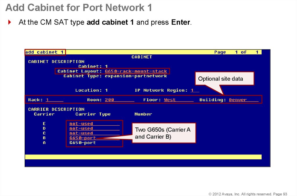
© 2012 Avaya, Inc. All rights reserved. Page 9293. Add Cabinet for Port Network 1
At the CM SAT type add cabinet 1 and press Enter.Optional site data
Two G650s (Carrier A
and Carrier B)
© 2012 Avaya, Inc. All rights reserved. Page 93
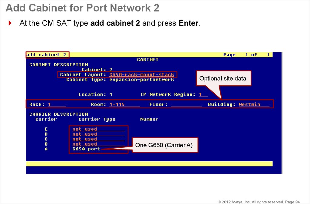
94. Add Cabinet for Port Network 2
At the CM SAT type add cabinet 2 and press Enter.Optional site data
One G650 (Carrier A)
© 2012 Avaya, Inc. All rights reserved. Page 94
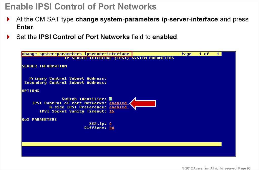
95. Enable IPSI Control of Port Networks
At the CM SAT type change system-parameters ip-server-interface and pressEnter.
Set the IPSI Control of Port Networks field to enabled.
© 2012 Avaya, Inc. All rights reserved. Page 95
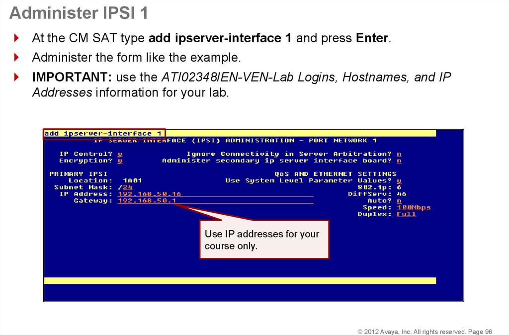
96. Administer IPSI 1
At the CM SAT type add ipserver-interface 1 and press Enter.Administer the form like the example.
IMPORTANT: use the ATI02348IEN-VEN-Lab Logins, Hostnames, and IP
Addresses information for your lab.
Use IP addresses for your
course only.
© 2012 Avaya, Inc. All rights reserved. Page 96
97. Administer IPSI 2
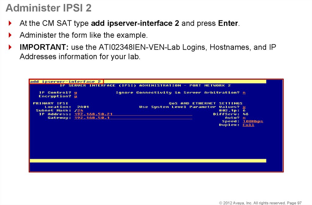
At the CM SAT type add ipserver-interface 2 and press Enter.Administer the form like the example.
IMPORTANT: use the ATI02348IEN-VEN-Lab Logins, Hostnames, and IP
Addresses information for your lab.
© 2012 Avaya, Inc. All rights reserved. Page 97
98. Check IPSI Status
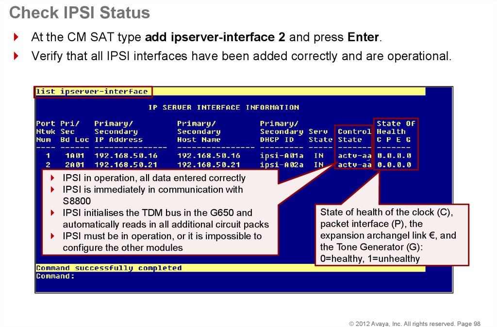
At the CM SAT type add ipserver-interface 2 and press Enter.Verify that all IPSI interfaces have been added correctly and are operational.
IPSI in operation, all data entered correctly
IPSI is immediately in communication with
S8800
IPSI initialises the TDM bus in the G650 and
automatically reads in all additional circuit packs
IPSI must be in operation, or it is impossible to
configure the other modules
State of health of the clock (C),
packet interface (P), the
expansion archangel link €, and
the Tone Generator (G):
0=healthy, 1=unhealthy
© 2012 Avaya, Inc. All rights reserved. Page 98
99. Enable Operation of IPSI Duplication
At the CM SAT type change system-parameters duplication and press Enter.Set the Enable Operation of IPSI Duplication field to y.
© 2012 Avaya, Inc. All rights reserved. Page 99
100. Duplicated IPSI Administration in CM
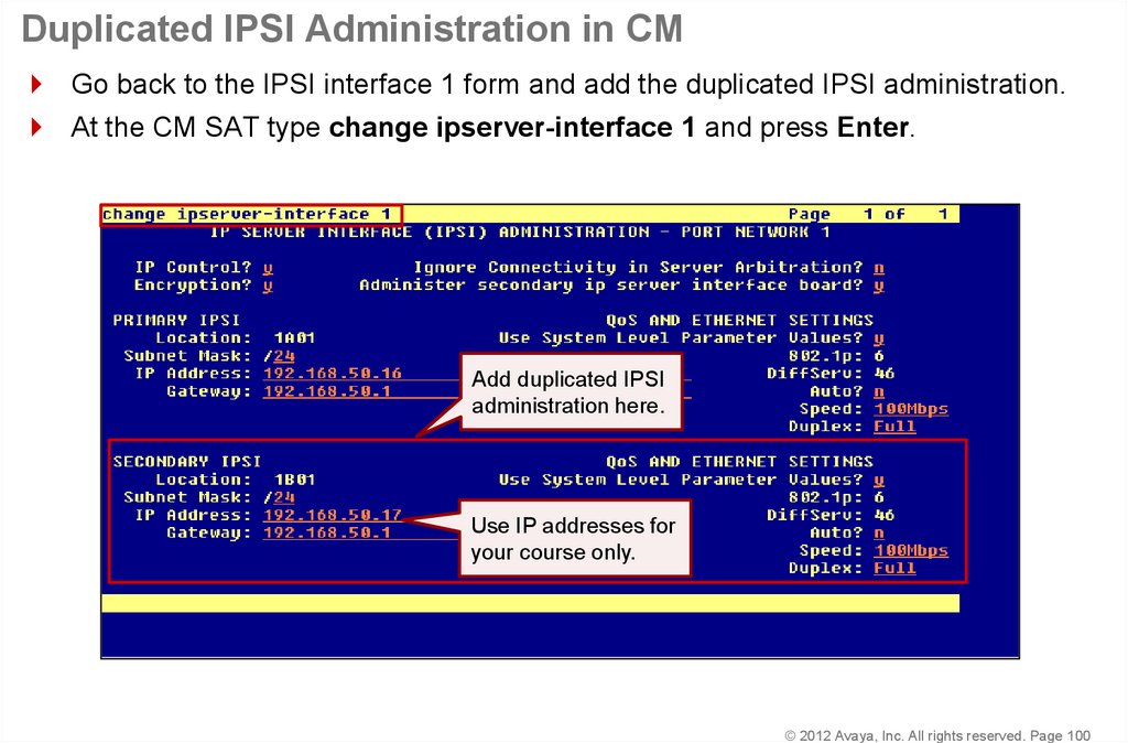
Go back to the IPSI interface 1 form and add the duplicated IPSI administration.At the CM SAT type change ipserver-interface 1 and press Enter.
Add duplicated IPSI
administration here.
Use IP addresses for
your course only.
© 2012 Avaya, Inc. All rights reserved. Page 100
101. Check IPSI Status
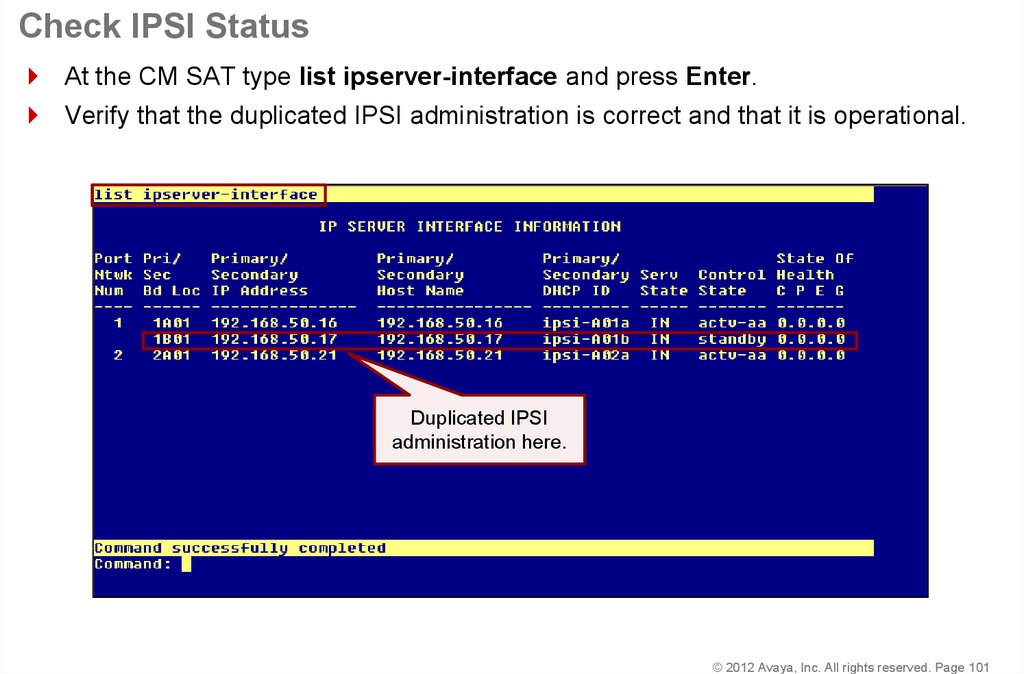
At the CM SAT type list ipserver-interface and press Enter.Verify that the duplicated IPSI administration is correct and that it is operational.
Duplicated IPSI
administration here.
© 2012 Avaya, Inc. All rights reserved. Page 101
102. Confirm System Configuration
At the CM SAT type list configuration all and press Enter.Verify that all circuit packs have been detected and appear in the report.
© 2012 Avaya, Inc. All rights reserved. Page 102
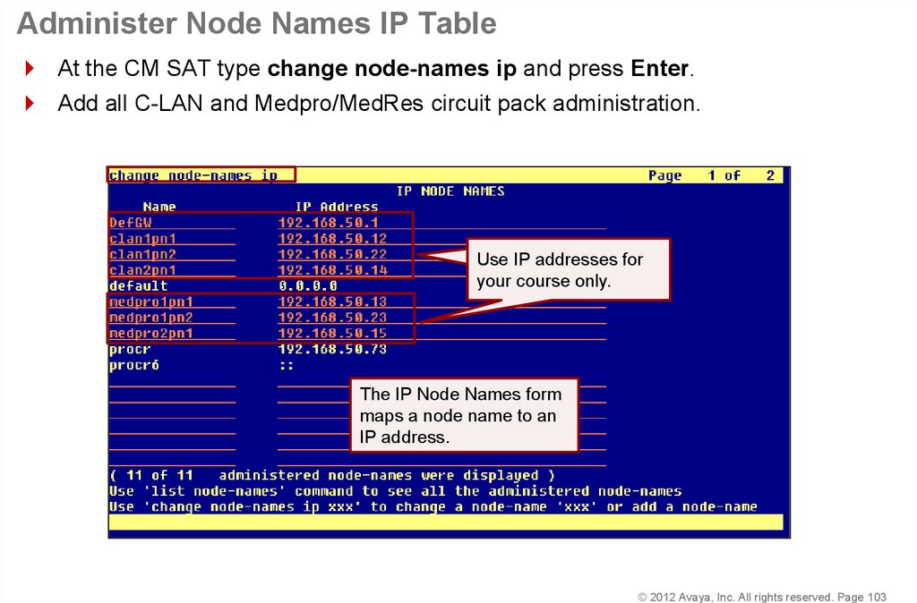
103. Administer Node Names IP Table
At the CM SAT type change node-names ip and press Enter.Add all C-LAN and Medpro/MedRes circuit pack administration.
Use IP addresses for
your course only.
The IP Node Names form
maps a node name to an
IP address.
© 2012 Avaya, Inc. All rights reserved. Page 103
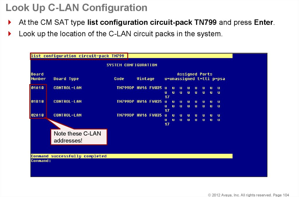
104. Look Up C-LAN Configuration
At the CM SAT type list configuration circuit-pack TN799 and press Enter.Look up the location of the C-LAN circuit packs in the system.
Note these C-LAN
addresses!
© 2012 Avaya, Inc. All rights reserved. Page 104
105. C-LAN 1 Administration
At the CM SAT type add ip-interface 01a10 and press Enter.Assign a Node Name for this interface and administer the form like the example.
Go to the next page.
Assign a Node
Name to this
interface.
© 2012 Avaya, Inc. All rights reserved. Page 105
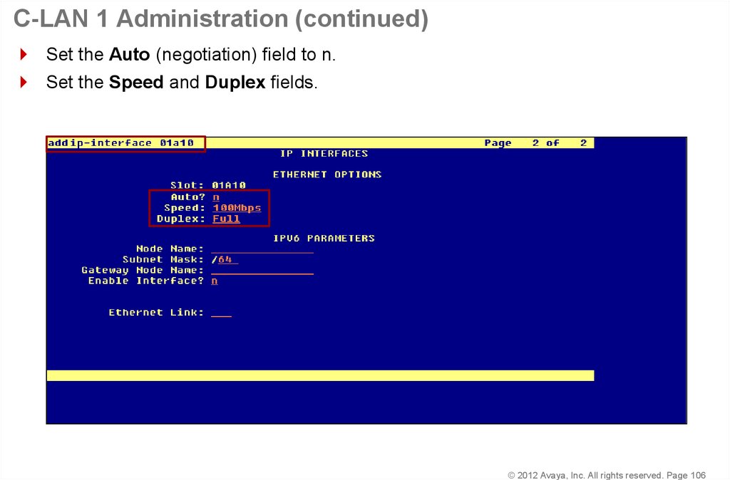
106. C-LAN 1 Administration (continued)
Set the Auto (negotiation) field to n.Set the Speed and Duplex fields.
© 2012 Avaya, Inc. All rights reserved. Page 106
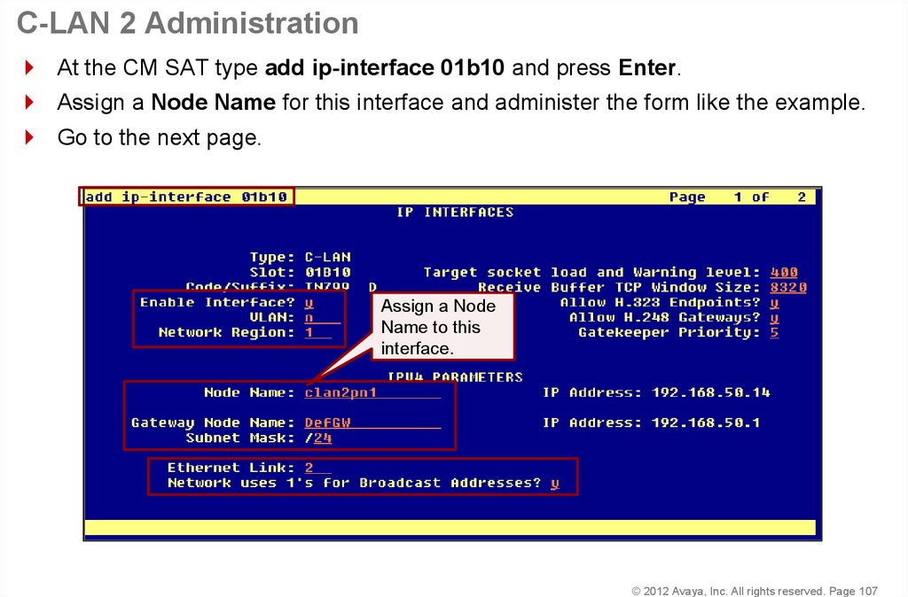
107. C-LAN 2 Administration
At the CM SAT type add ip-interface 01b10 and press Enter.Assign a Node Name for this interface and administer the form like the example.
Go to the next page.
Assign a Node
Name to this
interface.
© 2012 Avaya, Inc. All rights reserved. Page 107
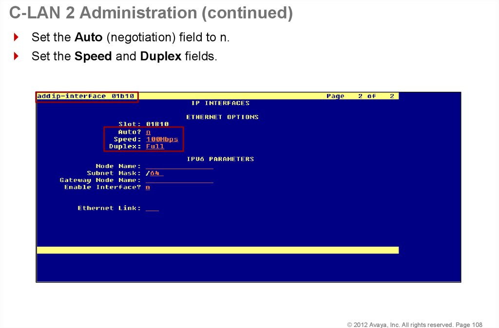
108. C-LAN 2 Administration (continued)
Set the Auto (negotiation) field to n.Set the Speed and Duplex fields.
© 2012 Avaya, Inc. All rights reserved. Page 108
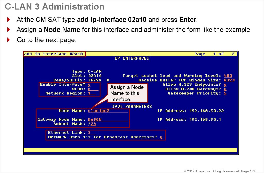
109. C-LAN 3 Administration
At the CM SAT type add ip-interface 02a10 and press Enter.Assign a Node Name for this interface and administer the form like the example.
Go to the next page.
Assign a Node
Name to this
interface.
© 2012 Avaya, Inc. All rights reserved. Page 109
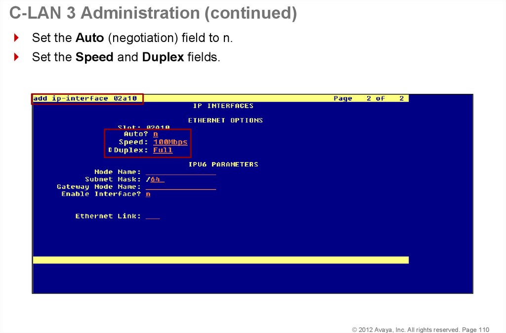
110. C-LAN 3 Administration (continued)
Set the Auto (negotiation) field to n.Set the Speed and Duplex fields.
© 2012 Avaya, Inc. All rights reserved. Page 110
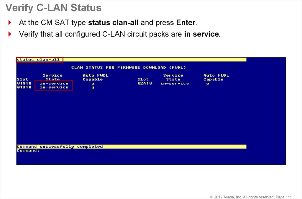
111. Verify C-LAN Status
At the CM SAT type status clan-all and press Enter.Verify that all configured C-LAN circuit packs are in service.
© 2012 Avaya, Inc. All rights reserved. Page 111
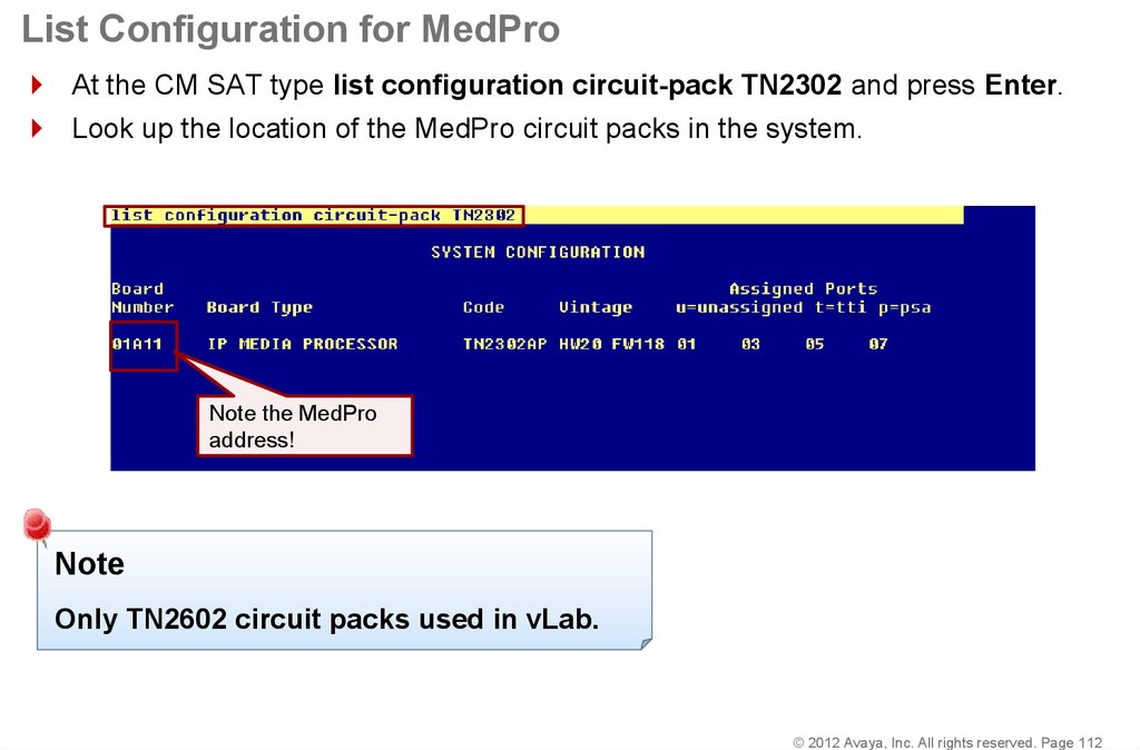
112. List Configuration for MedPro
At the CM SAT type list configuration circuit-pack TN2302 and press Enter.Look up the location of the MedPro circuit packs in the system.
Note the MedPro
address!
Note
Only TN2602 circuit packs used in vLab.
© 2012 Avaya, Inc. All rights reserved. Page 112
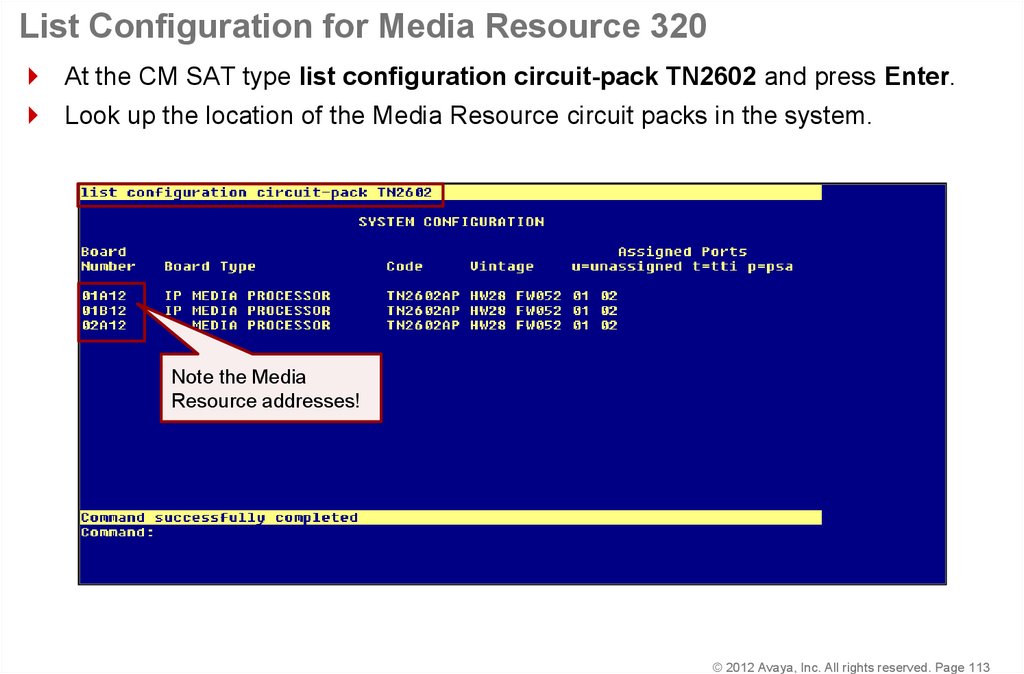
113. List Configuration for Media Resource 320
At the CM SAT type list configuration circuit-pack TN2602 and press Enter.Look up the location of the Media Resource circuit packs in the system.
Note the Media
Resource addresses!
© 2012 Avaya, Inc. All rights reserved. Page 113
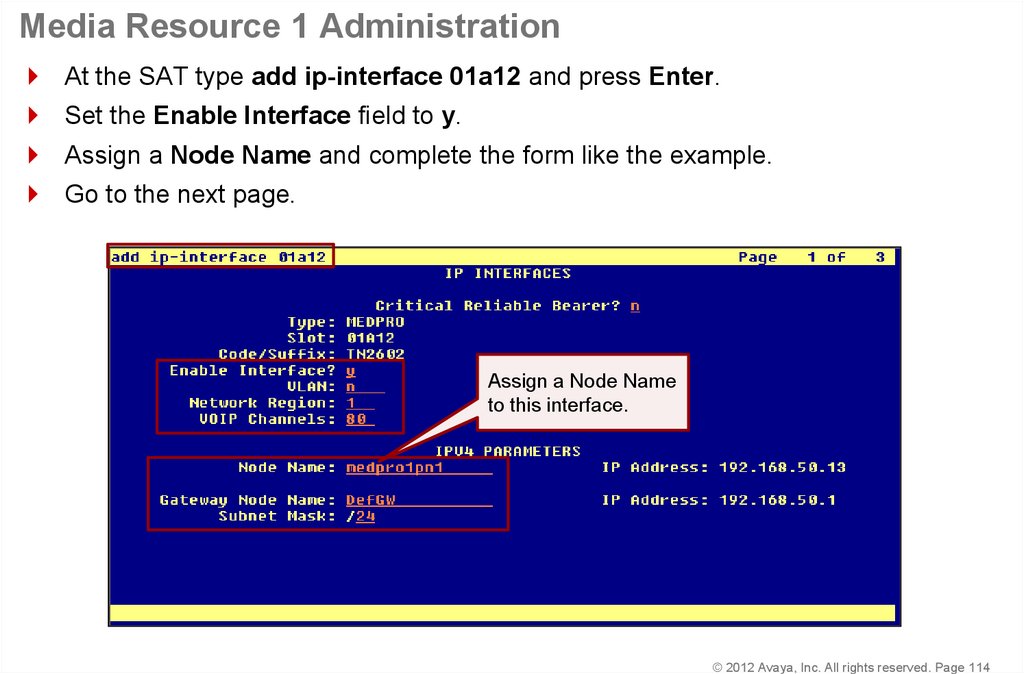
114. Media Resource 1 Administration
At the SAT type add ip-interface 01a12 and press Enter.Set the Enable Interface field to y.
Assign a Node Name and complete the form like the example.
Go to the next page.
Assign a Node Name
to this interface.
© 2012 Avaya, Inc. All rights reserved. Page 114
115. Media Resource 1 Administration (continued)
Set the Auto (negotiation) field to n.Set the Speed and Duplex fields.
© 2012 Avaya, Inc. All rights reserved. Page 115
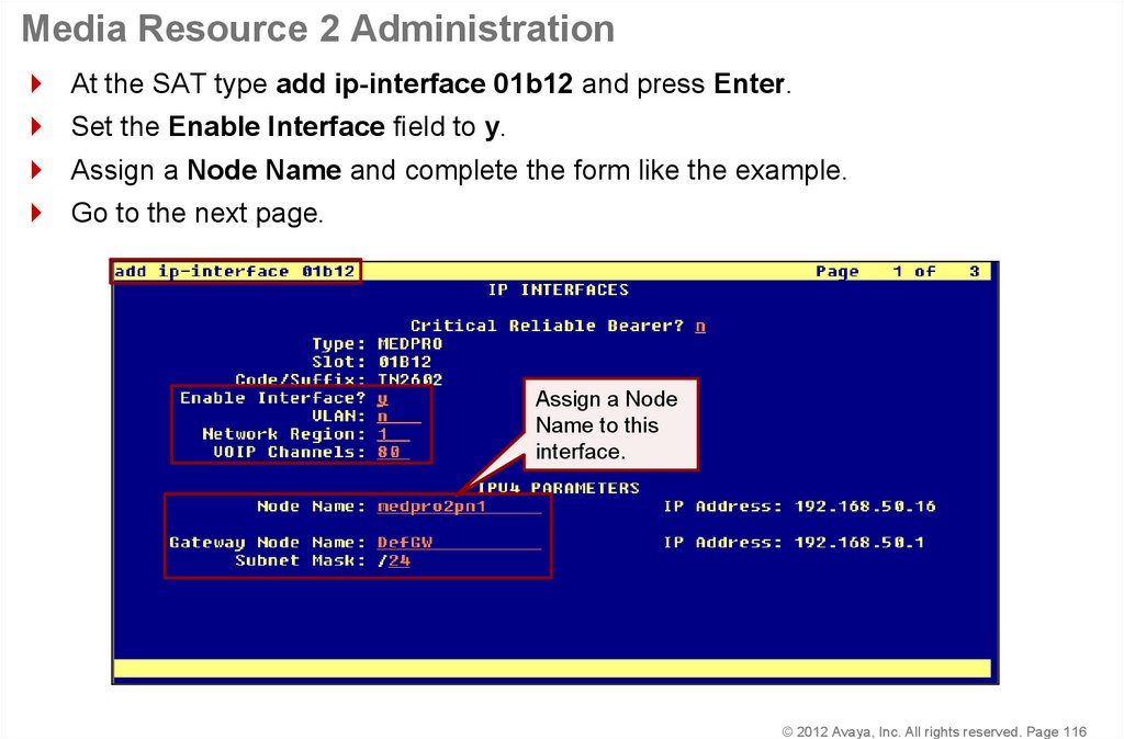
116. Media Resource 2 Administration
At the SAT type add ip-interface 01b12 and press Enter.Set the Enable Interface field to y.
Assign a Node Name and complete the form like the example.
Go to the next page.
Assign a Node
Name to this
interface.
© 2012 Avaya, Inc. All rights reserved. Page 116
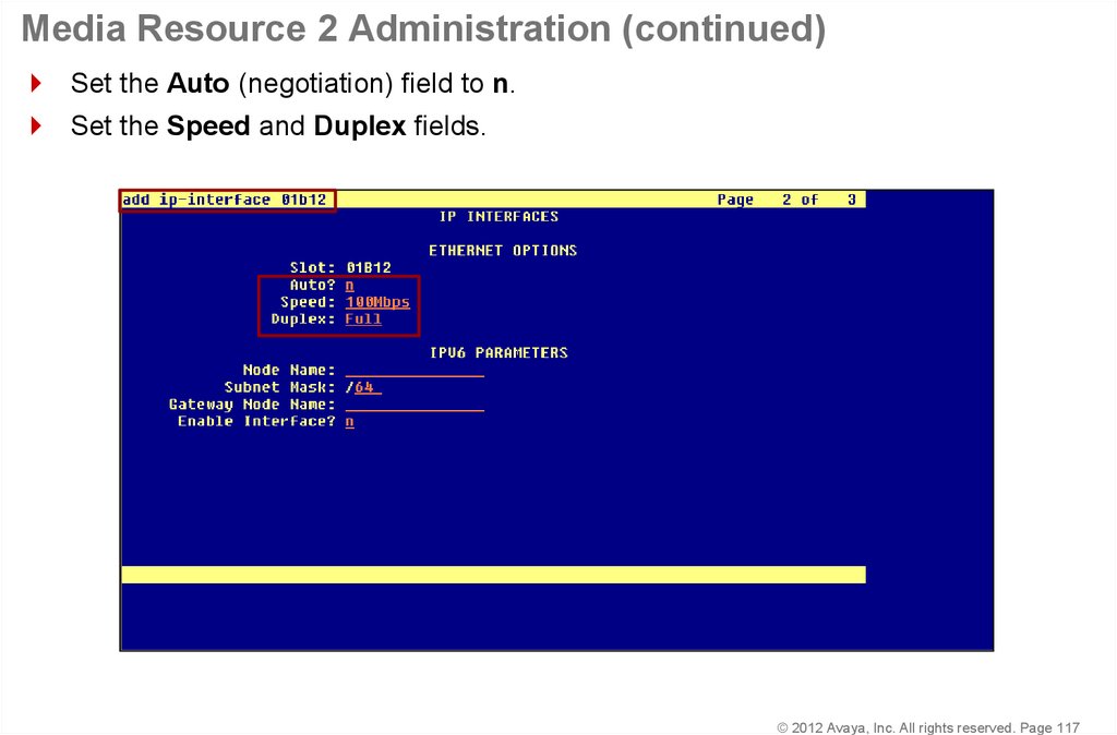
117. Media Resource 2 Administration (continued)
Set the Auto (negotiation) field to n.Set the Speed and Duplex fields.
© 2012 Avaya, Inc. All rights reserved. Page 117
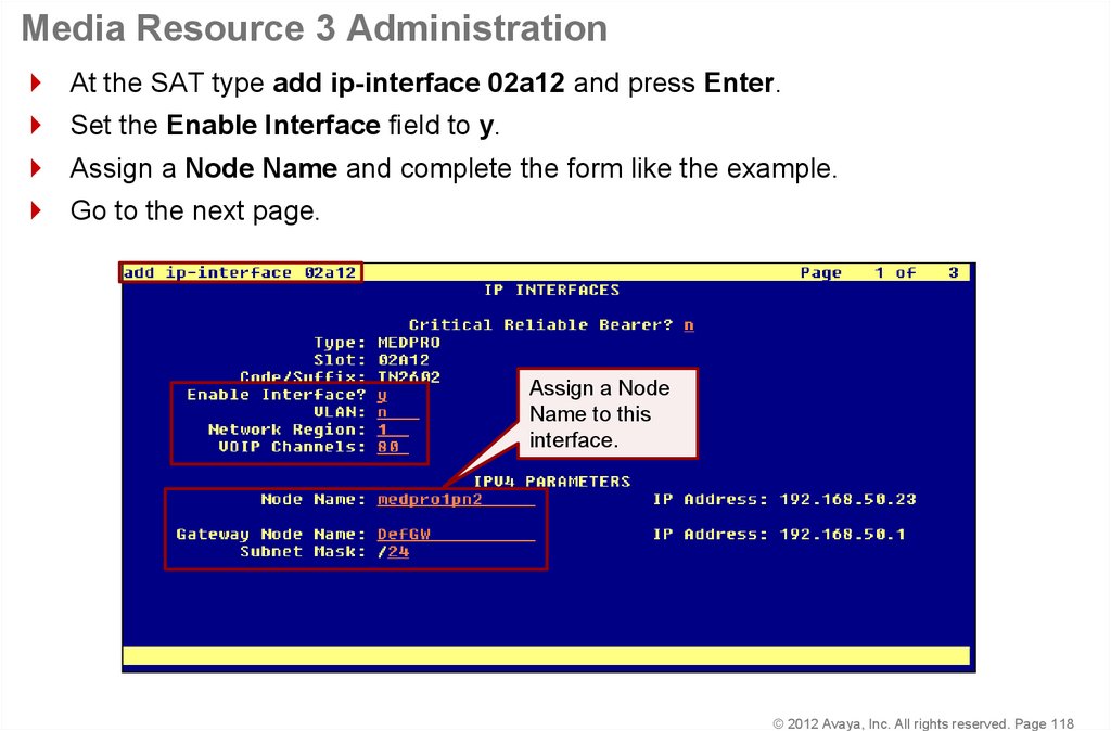
118. Media Resource 3 Administration
At the SAT type add ip-interface 02a12 and press Enter.Set the Enable Interface field to y.
Assign a Node Name and complete the form like the example.
Go to the next page.
Assign a Node
Name to this
interface.
© 2012 Avaya, Inc. All rights reserved. Page 118
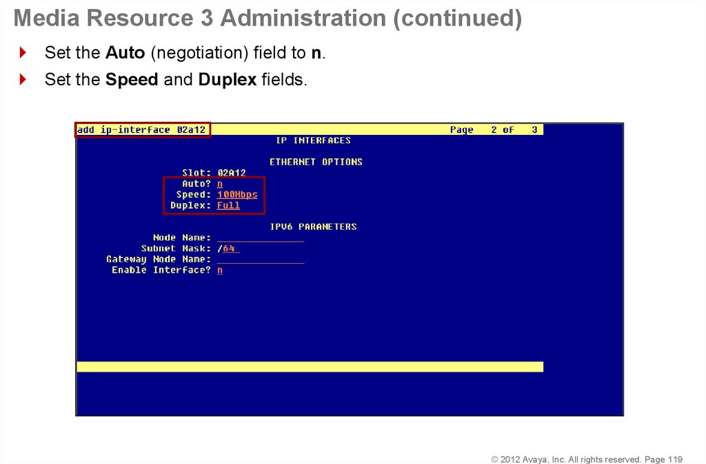
119. Media Resource 3 Administration (continued)
Set the Auto (negotiation) field to n.Set the Speed and Duplex fields.
© 2012 Avaya, Inc. All rights reserved. Page 119
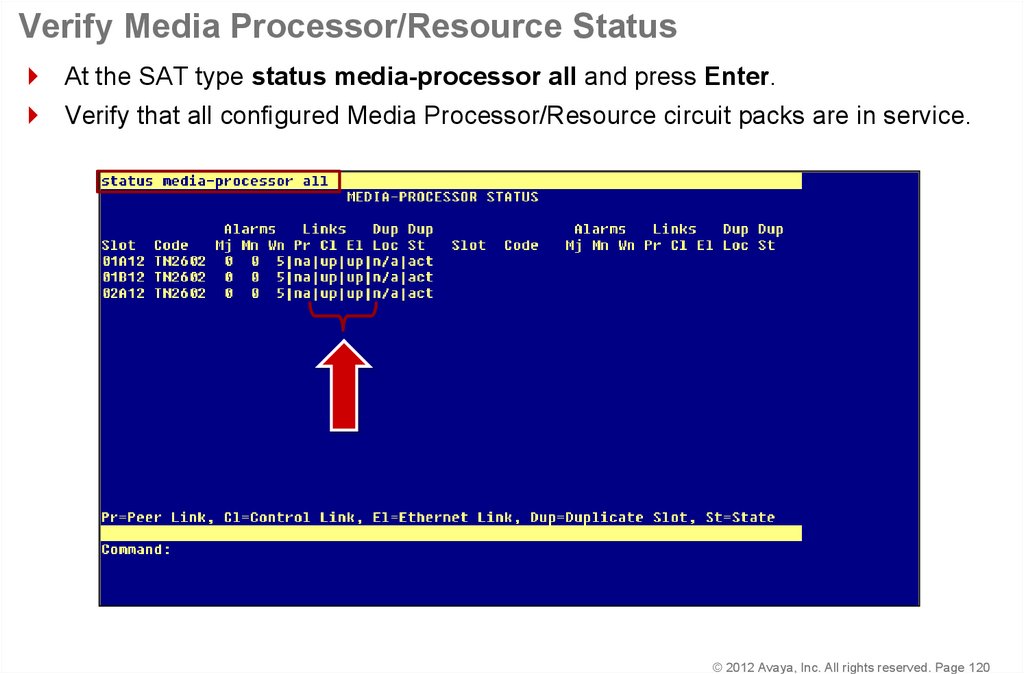
120. Verify Media Processor/Resource Status
At the SAT type status media-processor all and press Enter.Verify that all configured Media Processor/Resource circuit packs are in service.
© 2012 Avaya, Inc. All rights reserved. Page 120
121. Make a Test Call
© 2012 Avaya, Inc. All rights reserved.122. Administer CM Endpoints
© 2012 Avaya, Inc. All rights reserved.123. Administer CM Endpoints—Dial Plan
The dial plan interprets dialed digits.© 2012 Avaya, Inc. All rights reserved. Page 123
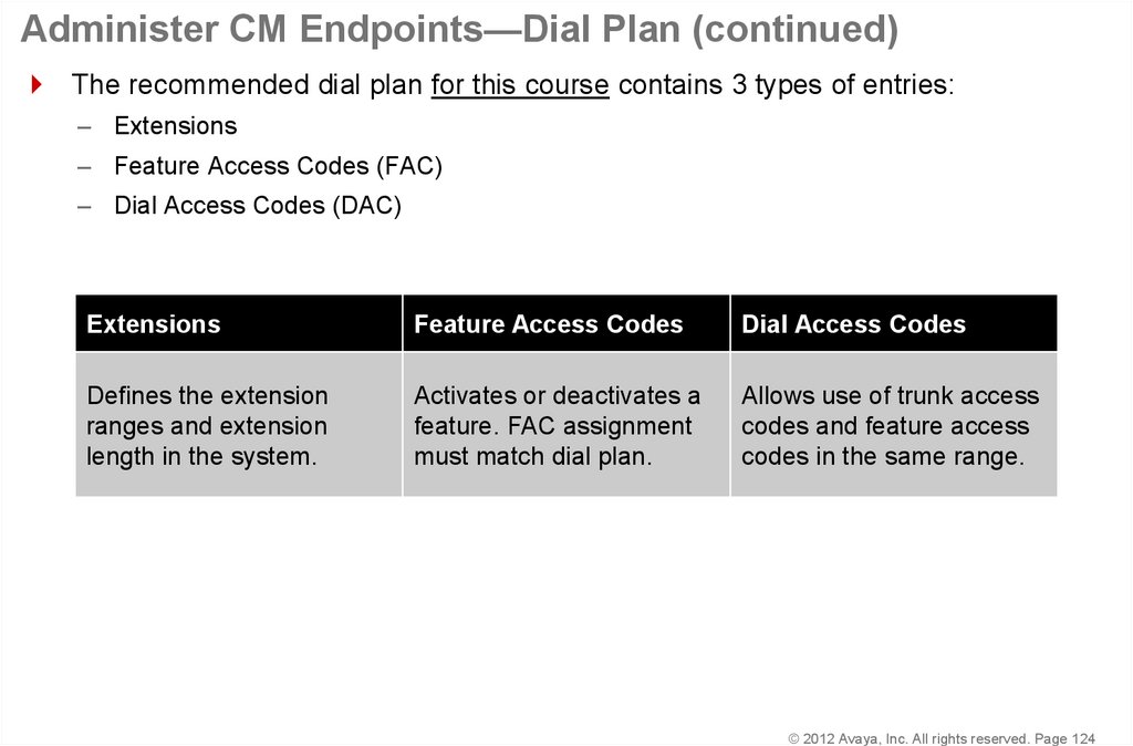
124. Administer CM Endpoints—Dial Plan (continued)
The recommended dial plan for this course contains 3 types of entries:– Extensions
– Feature Access Codes (FAC)
– Dial Access Codes (DAC)
Extensions
Feature Access Codes
Dial Access Codes
Defines the extension
ranges and extension
length in the system.
Activates or deactivates a
feature. FAC assignment
must match dial plan.
Allows use of trunk access
codes and feature access
codes in the same range.
© 2012 Avaya, Inc. All rights reserved. Page 124
125. Administer CM Endpoints—Dial Plan (continued)
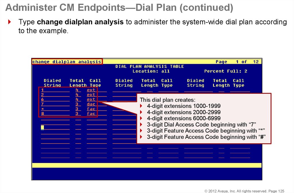
Type change dialplan analysis to administer the system-wide dial plan accordingto the example.
This dial plan creates:
4-digit extensions 1000-1999
4-digit extensions 2000-2999
4-digit extensions 6000-6999
3-digit Dial Access Code beginning with “7”
3-digit Feature Access Code beginning with “*”
3-digit Feature Access Code beginning with “#”
© 2012 Avaya, Inc. All rights reserved. Page 125
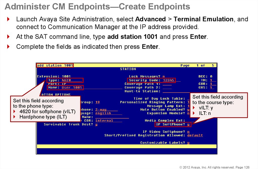
126. Administer CM Endpoints—Create Endpoints
Launch Avaya Site Administration, select Advanced > Terminal Emulation, andconnect to Communication Manager at the IP address provided.
At the SAT command line, type add station 1001 and press Enter.
Complete the fields as indicated then press Enter.
Set this field according
to the phone type:
4620 for softphone (vILT)
Hardphone type (ILT)
Set this field according
to the course type:
vILT: y
ILT: n
© 2012 Avaya, Inc. All rights reserved. Page 126
127. Administer CM Endpoints—Create Endpoints (continued)
Repeat the administration for extension 1002.At the SAT command line, type add station 1002 and press Enter.
Complete the fields as indicated then press Enter.
© 2012 Avaya, Inc. All rights reserved. Page 127
128. Administer CM Endpoints—Create Endpoints (continued)
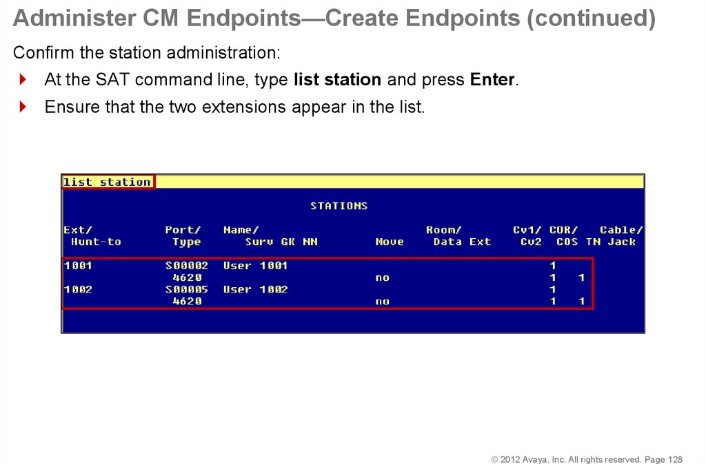
Confirm the station administration:At the SAT command line, type list station and press Enter.
Ensure that the two extensions appear in the list.
© 2012 Avaya, Inc. All rights reserved. Page 128
129. Administer one-X® Communicator
© 2012 Avaya, Inc. All rights reserved.130. Administer one-X® Communicator
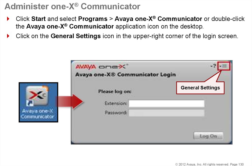
Click Start and select Programs > Avaya one-X® Communicator or double-clickthe Avaya one-X® Communicator application icon on the desktop.
Click on the General Settings icon in the upper-right corner of the login screen.
General Settings
© 2012 Avaya, Inc. All rights reserved. Page 130
131. Administer one-X® Communicator (continued)
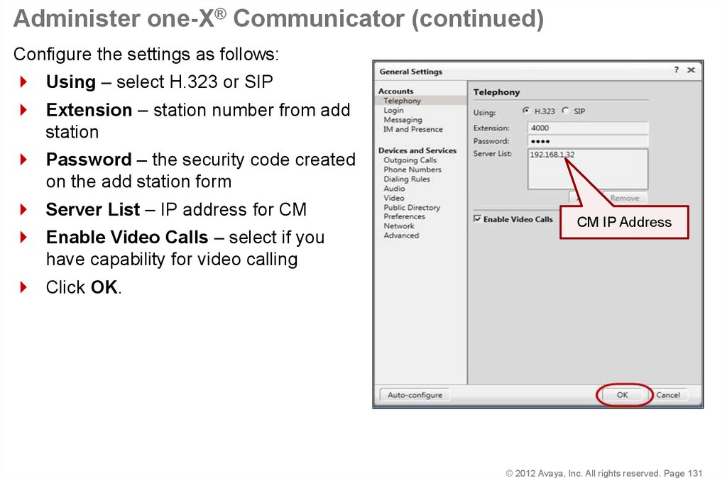
Configure the settings as follows:Using – select H.323 or SIP
Extension – station number from add
station
Password – the security code created
on the add station form
Server List – IP address for CM
Enable Video Calls – select if you
CM IP Address
have capability for video calling
Click OK.
© 2012 Avaya, Inc. All rights reserved. Page 131
132. Administer one-X® Communicator (continued)
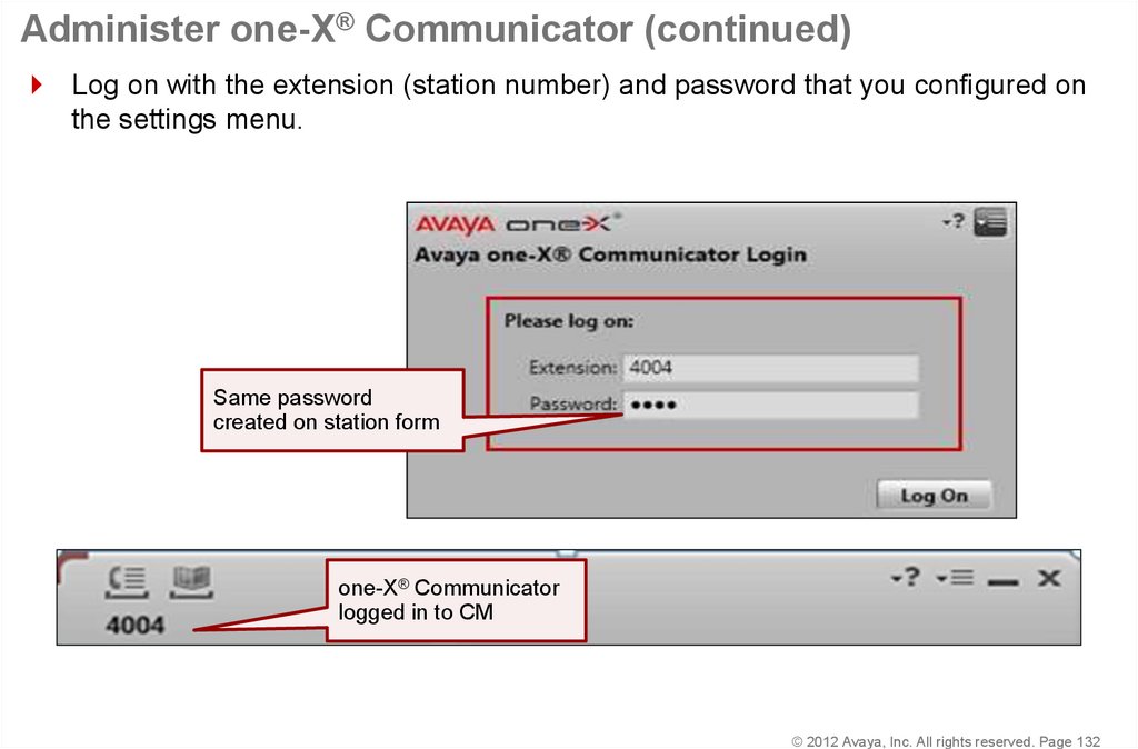
Log on with the extension (station number) and password that you configured onthe settings menu.
Same password
created on station form
one-X® Communicator
logged in to CM
© 2012 Avaya, Inc. All rights reserved. Page 132
133. Verify IP Telephone Registration
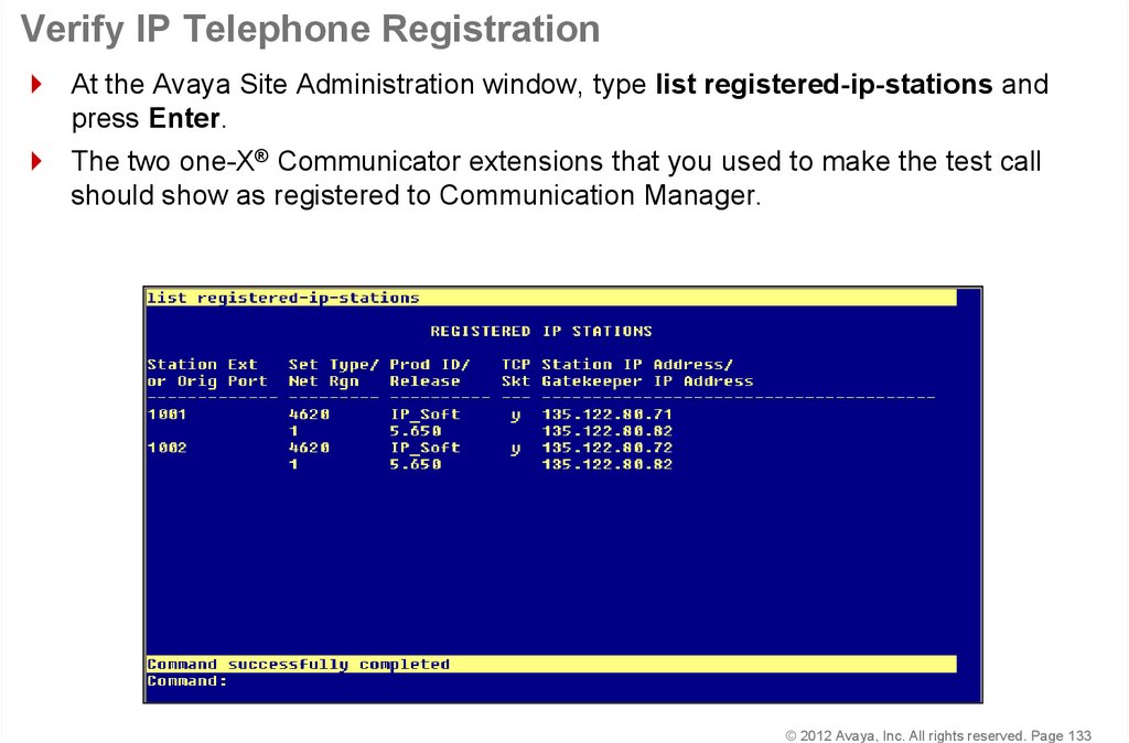
At the Avaya Site Administration window, type list registered-ip-stations andpress Enter.
The two one-X® Communicator extensions that you used to make the test call
should show as registered to Communication Manager.
© 2012 Avaya, Inc. All rights reserved. Page 133
134. Dial the Test Call
© 2012 Avaya, Inc. All rights reserved.135. Dial the Test Call
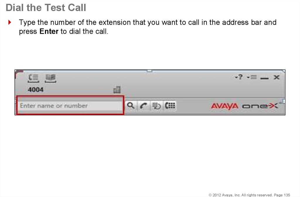
Type the number of the extension that you want to call in the address bar andpress Enter to dial the call.
© 2012 Avaya, Inc. All rights reserved. Page 135
136. Dial the Test Call (continued)
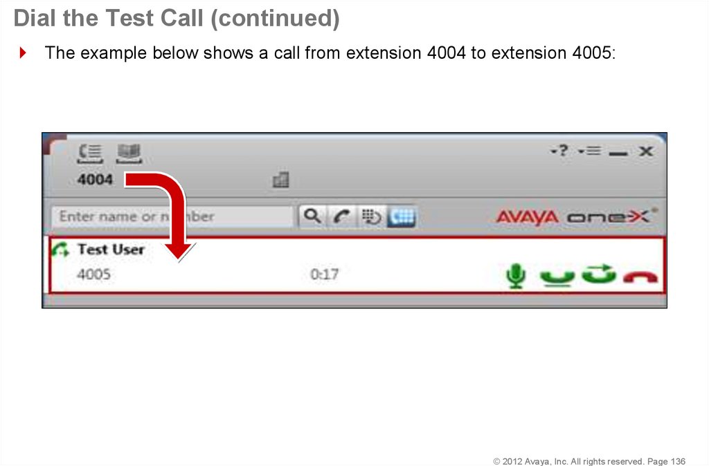
The example below shows a call from extension 4004 to extension 4005:© 2012 Avaya, Inc. All rights reserved. Page 136
137. Dial the Test Call (continued)
The Call Log at the bottom of the window shows the call status:© 2012 Avaya, Inc. All rights reserved. Page 137
138. Summary
You should now be able to:Cable and configure all hardware components
Install and configure the Communication
Manager – Embedded CM Main
Describe the Dot Release and Patch Guardian
functionality
Install the license file
Install Communication Manager patches
Configure the G450/G430 Gateway and media modules.
Make a test call
© 2012 Avaya, Inc. All rights reserved. Page 138










 Информатика


