


 Электроника
Похожие презентации:


")


Video module configuration
1.
We start at 1300AMS time = 1200UTCNW6000 TRAINING
Module 8 – Video Module Configuration
2.
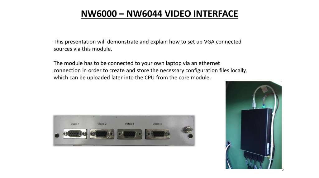
NW6000 – NW6044 VIDEO INTERFACEThis presentation will demonstrate and explain how to set up VGA connected
sources via this module.
The module has to be connected to your own laptop via an ethernet
connection in order to create and store the necessary configuration files locally,
which can be uploaded later into the CPU from the core module.
2
3.
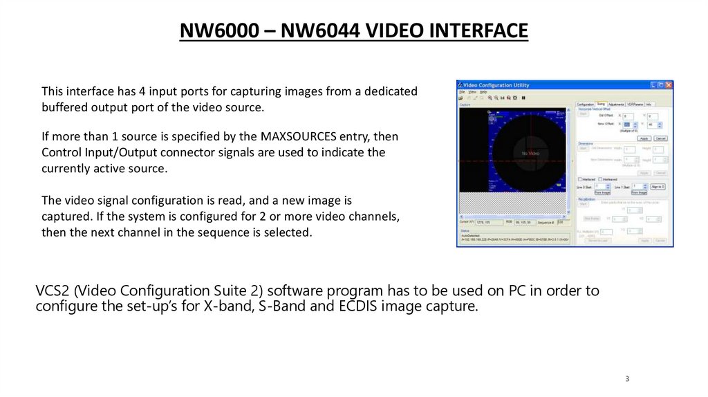
NW6000 – NW6044 VIDEO INTERFACEThis interface has 4 input ports for capturing images from a dedicated
buffered output port of the video source.
If more than 1 source is specified by the MAXSOURCES entry, then
Control Input/Output connector signals are used to indicate the
currently active source.
The video signal configuration is read, and a new image is
captured. If the system is configured for 2 or more video channels,
then the next channel in the sequence is selected.
VCS2 (Video Configuration Suite 2) software program has to be used on PC in order to
configure the set-up’s for X-band, S-Band and ECDIS image capture.
3
4.
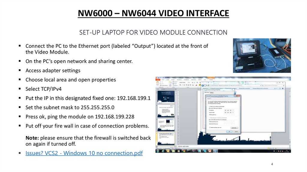
NW6000 – NW6044 VIDEO INTERFACESET-UP LAPTOP FOR VIDEO MODULE CONNECTION
Connect the PC to the Ethernet port (labeled “Output”) located at the front of
the Video Module.
On the PC’s open network and sharing center.
Access adapter settings
Choose local area and open properties
Select TCP/IPv4
Put the IP in this designated fixed one: 192.168.199.1
Set the subnet mask to 255.255.255.0
Press ok, ping the module on 192.168.199.228
Put off your fire wall in case of connection problems.
Note: please ensure that the firewall is switched back
on again if turned off.
Issues? VCS2 - Windows 10 no connection.pdf
4
5.
NW6000 – NW6044 VIDEO MODULE SPECIFICATIONSNormal image Size
1600 X 1200
24bit
85Hz
‘Interleaved’ Max Size
1920x1280
24bit
170Hz
(2 Images)
High resolution pictures (wide screen) can be captured, called interleaved picture grabbing.
5
6.
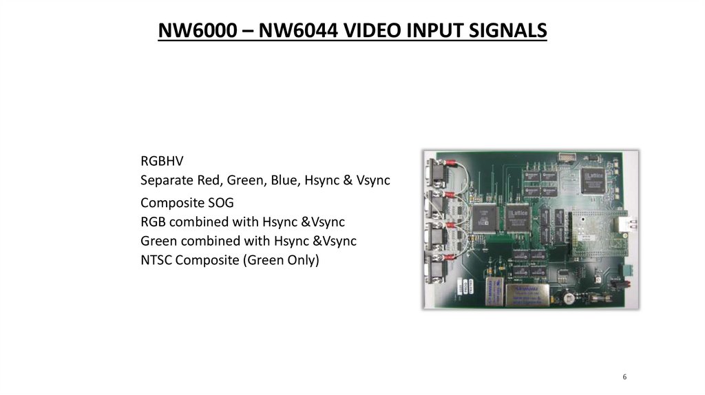
NW6000 – NW6044 VIDEO INPUT SIGNALSRGBHV
Separate Red, Green, Blue, Hsync & Vsync
Composite SOG
RGB combined with Hsync &Vsync
Green combined with Hsync &Vsync
NTSC Composite (Green Only)
6
7.
NW6000 – NW6044 VIDEO CAPTURE STEPSTo capture and properly store video data you need to:
1. Edit the VidChan*.ini File
This is done by using the VideoConfigSuite Version 4.3.0.2 also know as VCS2 (details later in
presentation) created inside your PC.
The utility generates a source specific VidChan*.ini file.
One VidChan*.ini file is required for each video input.
2. Save your VidChan*.ini file(s) and upload the vidchan’s into the Core Module.
3. Test Input Sources.
Test each Input (final review is to be playback of actual data using Playback’s Full-Size View
mode
7
8.
NW6000 – NW6044 SOFTWARE-VIDEOCONFIGSUITE 4.3.0.2 (VCS2)The suite runs from the executable file: VCS2.exe and
requires no other supporting files.
Has a built-in Auto-Detection routine which detects many of
the necessary parameters for the <VidChanX.ini> files
Existing <VidChanX.ini> files can also be directly modified
within this application (as they are text files)
8
9.
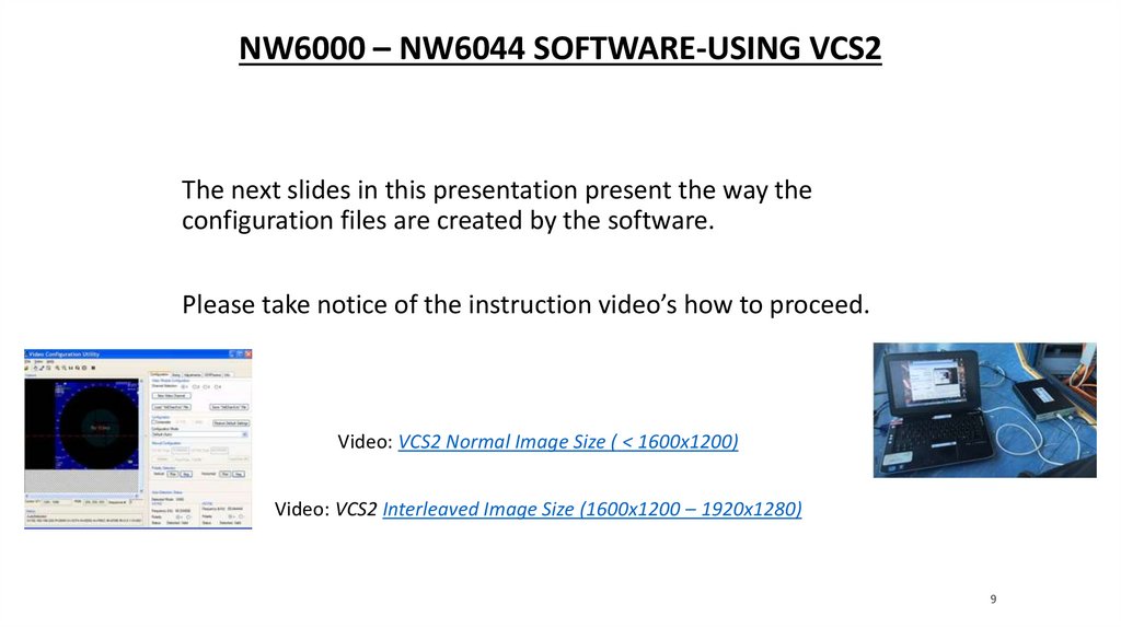
NW6000 – NW6044 SOFTWARE-USING VCS2The next slides in this presentation present the way the
configuration files are created by the software.
Please take notice of the instruction video’s how to proceed.
Video: VCS2 Normal Image Size ( < 1600x1200)
Video: VCS2 Interleaved Image Size (1600x1200 – 1920x1280)
9
10.
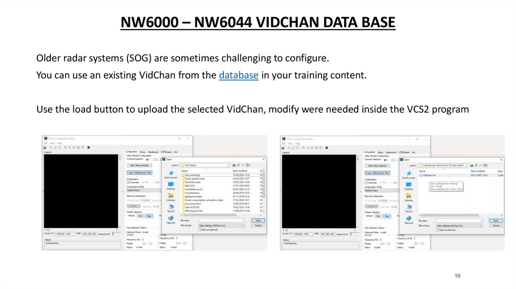
NW6000 – NW6044 VIDCHAN DATA BASEOlder radar systems (SOG) are sometimes challenging to configure.
You can use an existing VidChan from the database in your training content.
Use the load button to upload the selected VidChan, modify were needed inside the VCS2 program
10
11.
NW6000 – CONFIGURING NW6044 USING VCS2VCS2 – USER INTERFACES
The suite consists of five tab-accessible sections:
1.
Configuration (for video capture)
2.
Sizing (image size and shape)
3.
Adjustments (image quality)
4.
Info (provides statistics on capture image)
11
12.
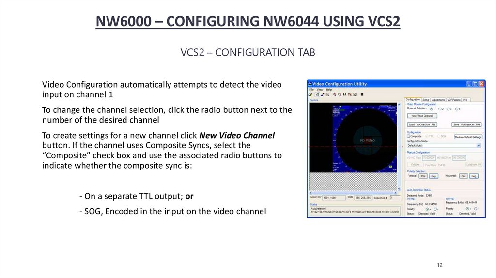
NW6000 – CONFIGURING NW6044 USING VCS2VCS2 – CONFIGURATION TAB
Video Configuration automatically attempts to detect the video
input on channel 1
To change the channel selection, click the radio button next to the
number of the desired channel
To create settings for a new channel click New Video Channel
button. If the channel uses Composite Syncs, select the
“Composite” check box and use the associated radio buttons to
indicate whether the composite sync is:
- On a separate TTL output; or
- SOG, Encoded in the input on the video channel
12
13.
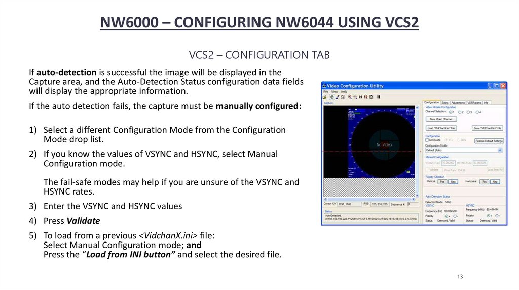
NW6000 – CONFIGURING NW6044 USING VCS2VCS2 – CONFIGURATION TAB
If auto-detection is successful the image will be displayed in the
Capture area, and the Auto-Detection Status configuration data fields
will display the appropriate information.
If the auto detection fails, the capture must be manually configured:
1) Select a different Configuration Mode from the Configuration
Mode drop list.
2) If you know the values of VSYNC and HSYNC, select Manual
Configuration mode.
The fail-safe modes may help if you are unsure of the VSYNC and
HSYNC rates.
3) Enter the VSYNC and HSYNC values
4) Press Validate
5) To load from a previous <VidchanX.ini> file:
Select Manual Configuration mode; and
Press the “Load from INI button” and select the desired file.
13
14.
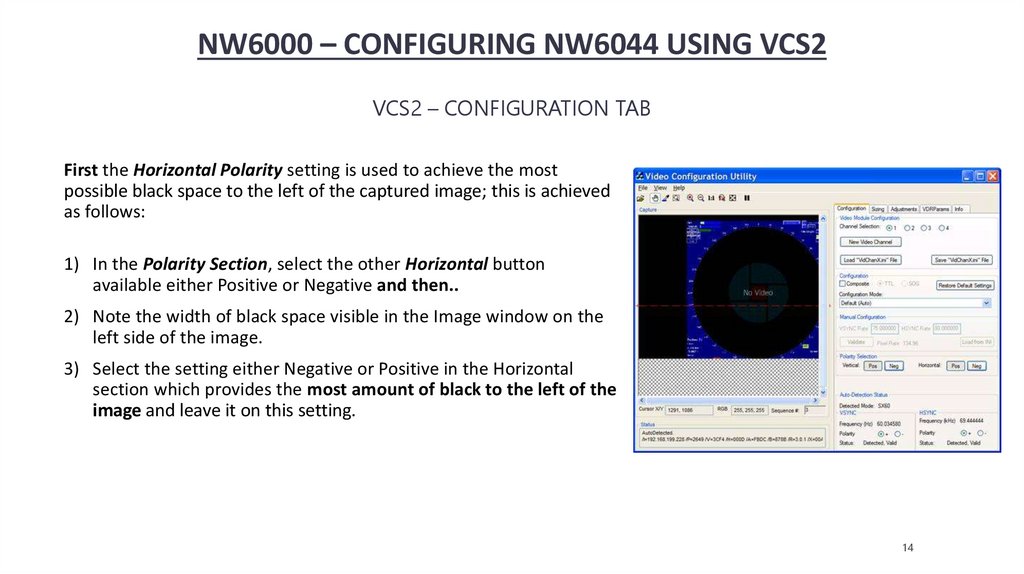
NW6000 – CONFIGURING NW6044 USING VCS2VCS2 – CONFIGURATION TAB
First the Horizontal Polarity setting is used to achieve the most
possible black space to the left of the captured image; this is achieved
as follows:
1) In the Polarity Section, select the other Horizontal button
available either Positive or Negative and then..
2) Note the width of black space visible in the Image window on the
left side of the image.
3) Select the setting either Negative or Positive in the Horizontal
section which provides the most amount of black to the left of the
image and leave it on this setting.
14
15.
NW6000 – CONFIGURING NW6044 USING VCS2VCS2 – CONFIGURATION TAB
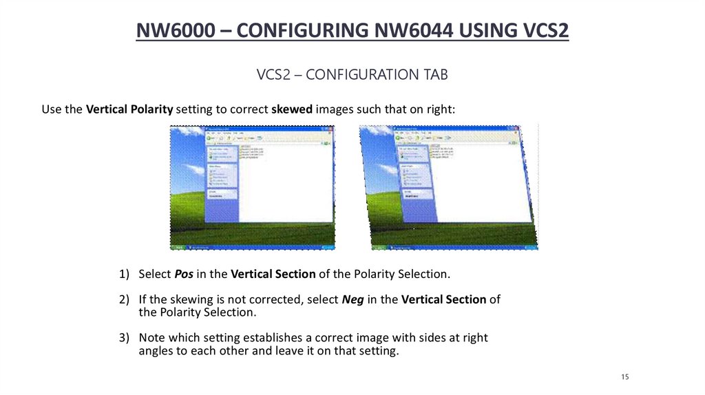
Use the Vertical Polarity setting to correct skewed images such that on right:
1) Select Pos in the Vertical Section of the Polarity Selection.
2) If the skewing is not corrected, select Neg in the Vertical Section of
the Polarity Selection.
3) Note which setting establishes a correct image with sides at right
angles to each other and leave it on that setting.
15
16.
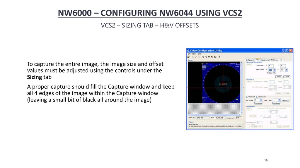
NW6000 – CONFIGURING NW6044 USING VCS2VCS2 – SIZING TAB – H&V OFFSETS
To capture the entire image, the image size and offset
values must be adjusted using the controls under the
Sizing tab
A proper capture should fill the Capture window and keep
all 4 edges of the image within the Capture window
(leaving a small bit of black all around the image)
16
17.
NW6000 – CONFIGURING NW6044 USING VCS2VCS2 – SIZING TAB – H&V OFFSETS
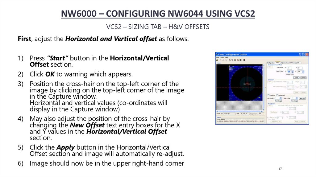
First, adjust the Horizontal and Vertical offset as follows:
1) Press “Start” button in the Horizontal/Vertical
Offset section.
2) Click OK to warning which appears.
3) Position the cross-hair on the top-left corner of the
image by clicking on the top-left corner of the image
in the Capture window.
Horizontal and vertical values (co-ordinates will
display in the Capture window)
4) May also adjust the position of the cross-hair by
changing the New Offset text entry boxes for the X
and Y values in the Horizontal/Vertical Offset
section.
5) Click the Apply button in the Horizontal/Vertical
Offset section and image will automatically re-adjust.
6) Image should now be in the upper right-hand corner
17
18.
NW6000 – CONFIGURING NW6044 USING VCS2VCS2 – SIZING TAB – DIMENSIONS
Second, If part of the image is not visible in the Capture window after it is moved to the upper left corner, it
shall be necessary to adjust the image height and/or width as follows :
1) Click the “Start” button on the Dimensions section of the Sizing page
2) Click OK to warning which appears
3) Click and drag the cursor on the image to reveal a rectangle that defines the image size
4) Click and drag the rectangle in the red transparent area
5) Pan the image outside the current viewing area to select a larger size
6) Alternatively, enter a Width and Height number in boxes
7) Click the Apply button in the lower right corner of the Dimensions section
8) The “Extents Changed” dialogue box confirms that the image size is adjusted; now click OK
18
19.
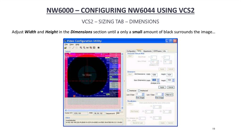
NW6000 – CONFIGURING NW6044 USING VCS2VCS2 – SIZING TAB – DIMENSIONS
Adjust Width and Height in the Dimensions section until a only a small amount of black surrounds the image…
19
20.
NW6000 – CONFIGURING NW6044 USING VCS2VCS2 – SIZING TAB – DIMENSIONS
Second, If part of the image is not visible in the Capture window after it is moved to the upper left corner, it
shall be necessary to adjust the image height and/or width as follows :
1) Click the “Start” button on the Dimensions section of the Sizing page
2) Click OK to warning which appears
3) Click and drag the cursor on the image to reveal a rectangle that defines the image size
4) Click and drag the rectangle in the red transparent area
5) Pan the image outside the current viewing area to select a larger size
6) Alternatively, enter a Width and Height number in boxes
7) Click the Apply button in the lower right corner of the Dimensions section
8) The “Extents Changed” dialogue box confirms that the image size is adjusted now click OK
20
21.
NW6000 – CONFIGURING NW6044 USING VCS2VCS2 – SIZING TAB – INTERLEAVED IMAGE
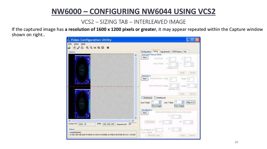
If the captured image has a resolution of 1600 x 1200 pixels or greater, it may appear repeated within the Capture window
shown on right..
21
22.
NW6000 – CONFIGURING NW6044 USING VCS2VCS2 – SIZING TAB – INTERLEAVED IMAGE
In order to correct this image it must be properly interleaved. Complete the following steps:
1) Click the Sizing tab to open the Sizing page.
2) Click the Start button in the Horizontal/Vertical Offset section.
3) Use the New Offset X scroll box and Y scroll box to move the image as close to the top left hand corner of the
Capture window.
4) Use Zooming options, determine the top edge of both images.
5) The Line 0 Start is usually be left at 0 and Line 1 Start should be adjusted.
6) Click the Interleaved checkbox to activate Interleaved mode.
7) If the image blurry, adjust Line 1 Start one value at a time until it looks correct.
22
23.
NW6000 – CONFIGURING NW6044 USING VCS2VCS2 – SIZING TAB – RECALIBRATION
The following steps are used to recalibrate the captured image:
1) Locate a circle in the radar image. A Variable Range Marker (VRM) or range ring, available on most radar images
are good
2) Click the Start button in the Recalibration section at the bottom of the Sizing page
3) In the Capture window click the Pick Points button to select the 4 points of the circle in order.
4) When 4 points of the circle are selected, click the Apply button and this applies the adjusted value of the Phase
Lock Loop (PLL) Multiplier Number (N)
5) Retry step 4, if necessary, until image aspect ratio is correct
6) Adjust H/V Offset until image is in the upper left corner of the capture window.
Note:
With many radar images, it may be difficult to determine the true upper left corner of the captured image.
The installer may have to adjust the image’s position a number of times, to ensure it is as close as possible to the top
left corner without losing any part of the image.
23
24.
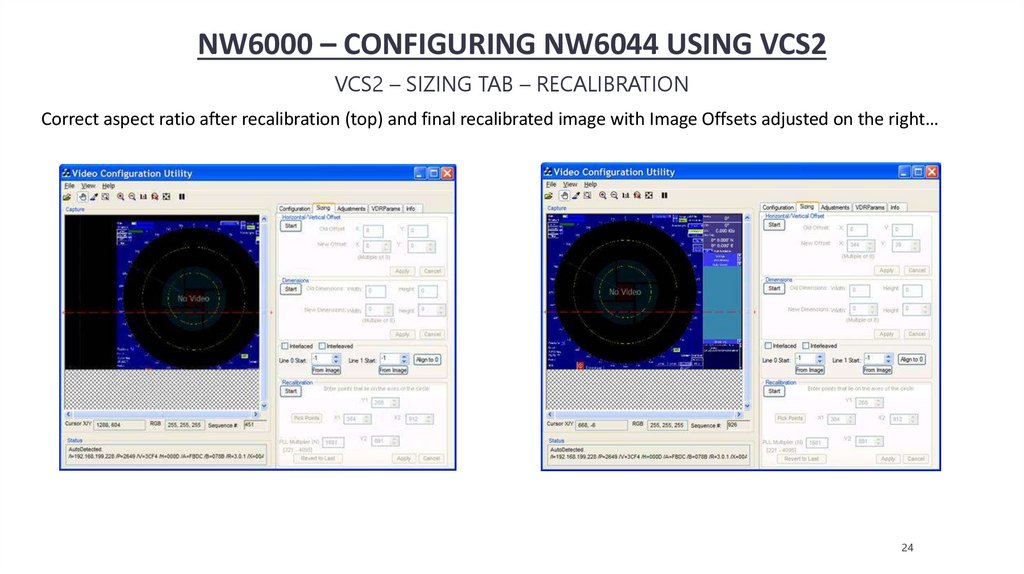
NW6000 – CONFIGURING NW6044 USING VCS2VCS2 – SIZING TAB – RECALIBRATION
Correct aspect ratio after recalibration (top) and final recalibrated image with Image Offsets adjusted on the right…
24
25.
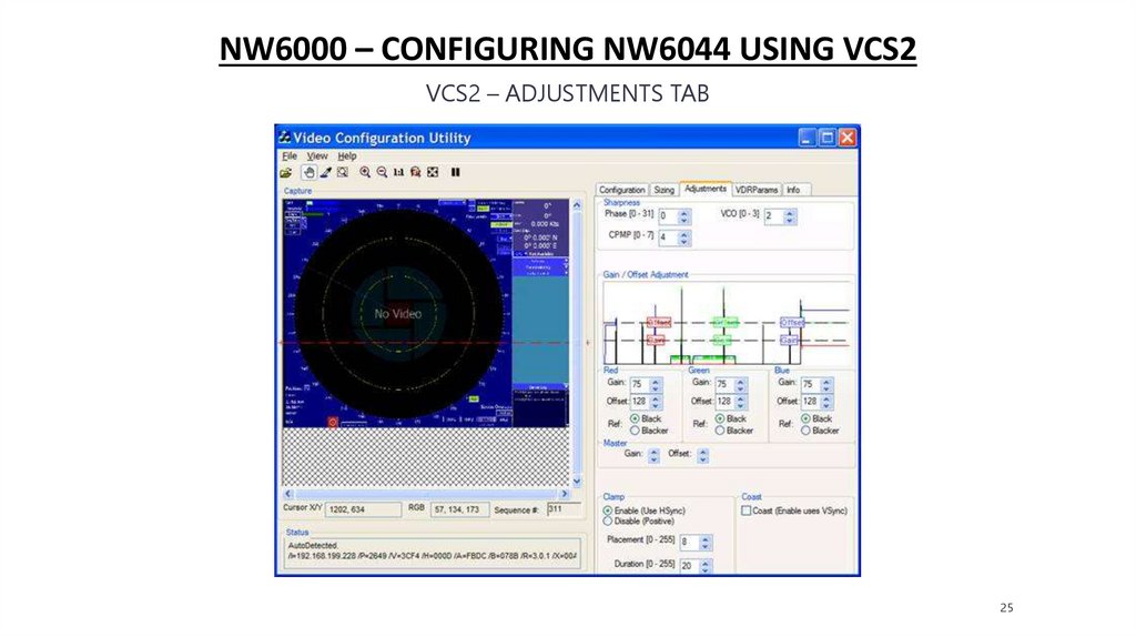
NW6000 – CONFIGURING NW6044 USING VCS2VCS2 – ADJUSTMENTS TAB
25
26.
NW6000 – CONFIGURING NW6044 USING VCS2VCS2 – ADJUSTMENT TAB – SHARPNESS - PHASE
The Sharpness section offers three scroll boxes to adjust the Phase, charge pump (CPMP), and the voltage-controlled
oscillators (VCO).
1) Phase
If image displays pixilation (visible noise), banding, and/or soft edges. This means the image phase must be
adjusted.
To adjust the Phase:
a. Enter a value or clicking the up/down controls on the Phase scroll box
(The range available for adjustment is 0 to 31.)
b. The image changes immediately to reflect the change. Continue to adjust
the number until the image is sharp.
26
27.
NW6000 – CONFIGURING NW6044 USING VCS2VCS2 – ADJUSTMENT TAB – SHARPNESS - CPMP
2) CPMP (Charge Pump)
When the image phase is sharpened, minor oscillation may still appear in the image. If so, it may be necessary to adjust
the image CPMP:
a) Check for oscillations at either the top of the image or near any straight black lines where they are
most apparent.
b) Note the image quality and use the CPMP scroll box to set CPMP between 0 and 3.
c) Image is automatically updated to show change.
d) Note the image quality for improvement; and…
e) Make further adjustments as necessary
27
28.
NW6000 – CONFIGURING NW6044 USING VCS2VCS2 – ADJUSTMENT TAB – SHARPNESS - CPMP
2.) CPMP (Charge Pump)
When the image phase is sharpened, minor oscillation may still appear in the image. If so it may
be necessary to adjust the image CPMP:
- Check for oscillations at either the top of the image or near any straight black
lines where they are most apparent
- Note the image quality and use the CPMP scroll box to set CPMP between 0 and 3
- Image is automatically updated to show change
- Note the image quality for improvement; and
- Make further adjustments as necessary
28
29.
NW6000 – CONFIGURING NW6044 USING VCS2VCS2 – ADJUSTMENT TAB – SHARPNESS – VOLTAGE-CONTROLLED OSCILLATOR (VCO)
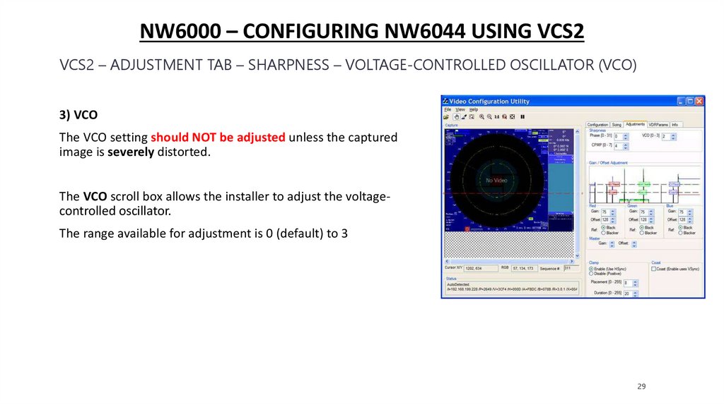
3) VCO
The VCO setting should NOT be adjusted unless the captured
image is severely distorted.
The VCO scroll box allows the installer to adjust the voltagecontrolled oscillator.
The range available for adjustment is 0 (default) to 3
29
30.
NW6000 – CONFIGURING NW6044 USING VCS2VCS2 – ADJUSTMENT TAB – GAIN/OFFSET
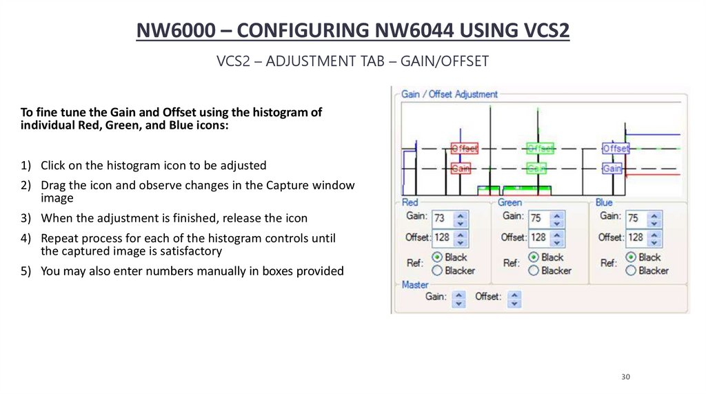
To fine tune the Gain and Offset using the histogram of
individual Red, Green, and Blue icons:
1) Click on the histogram icon to be adjusted
2) Drag the icon and observe changes in the Capture window
image
3) When the adjustment is finished, release the icon
4) Repeat process for each of the histogram controls until
the captured image is satisfactory
5) You may also enter numbers manually in boxes provided
30
31.
NW6000 – CONFIGURING NW6044 USING VCS2VCS2 – ADJUSTMENT TAB – CLAMP
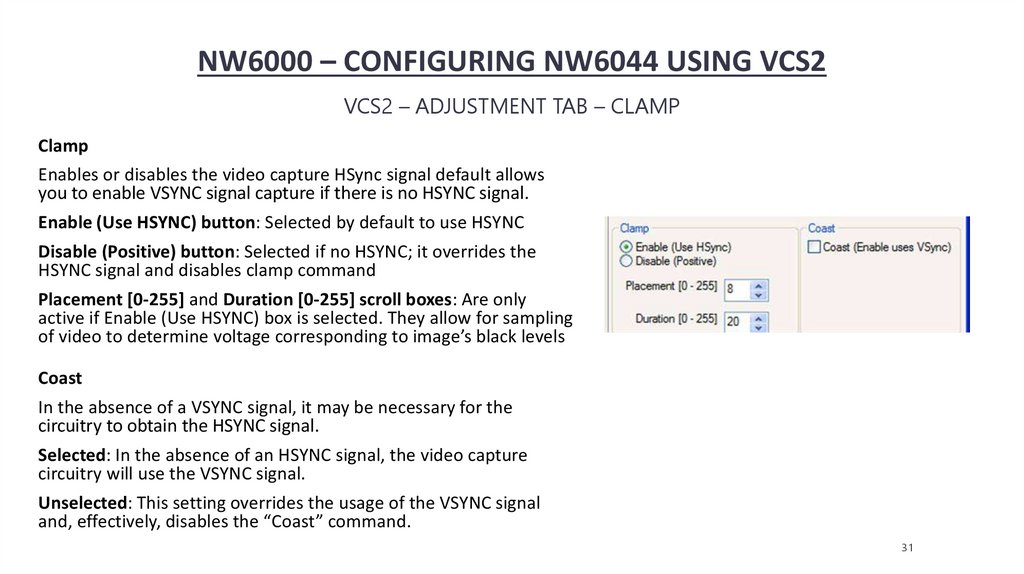
Clamp
Enables or disables the video capture HSync signal default allows
you to enable VSYNC signal capture if there is no HSYNC signal.
Enable (Use HSYNC) button: Selected by default to use HSYNC
Disable (Positive) button: Selected if no HSYNC; it overrides the
HSYNC signal and disables clamp command
Placement [0-255] and Duration [0-255] scroll boxes: Are only
active if Enable (Use HSYNC) box is selected. They allow for sampling
of video to determine voltage corresponding to image’s black levels
Coast
In the absence of a VSYNC signal, it may be necessary for the
circuitry to obtain the HSYNC signal.
Selected: In the absence of an HSYNC signal, the video capture
circuitry will use the VSYNC signal.
Unselected: This setting overrides the usage of the VSYNC signal
and, effectively, disables the “Coast” command.
31
32.
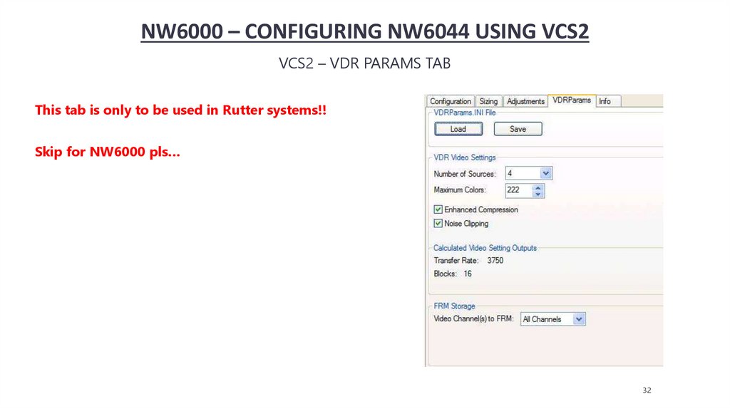
NW6000 – CONFIGURING NW6044 USING VCS2VCS2 – VDR PARAMS TAB
This tab is only to be used in Rutter systems!!
Skip for NW6000 pls…
32
33.
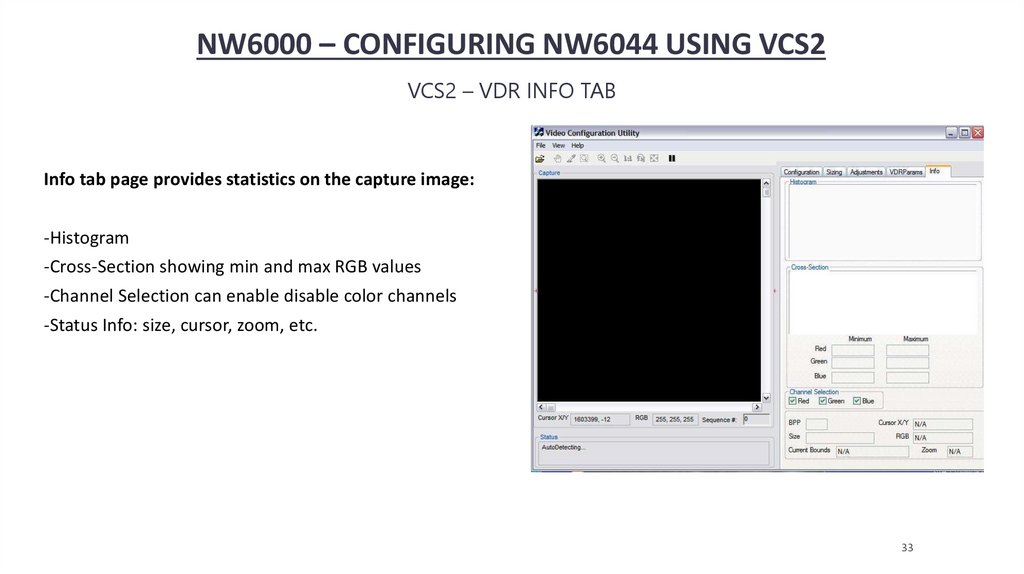
NW6000 – CONFIGURING NW6044 USING VCS2VCS2 – VDR INFO TAB
Info tab page provides statistics on the capture image:
-Histogram
-Cross-Section showing min and max RGB values
-Channel Selection can enable disable color channels
-Status Info: size, cursor, zoom, etc.
33
34.
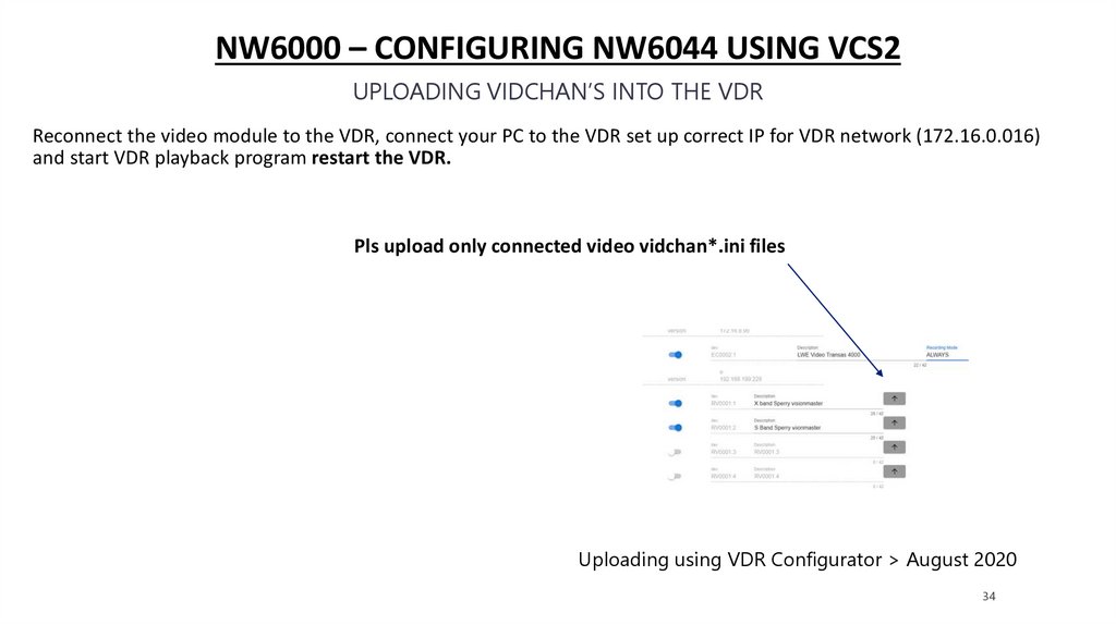
NW6000 – CONFIGURING NW6044 USING VCS2UPLOADING VIDCHAN’S INTO THE VDR
Reconnect the video module to the VDR, connect your PC to the VDR set up correct IP for VDR network (172.16.0.016)
and start VDR playback program restart the VDR.
Pls upload only connected video vidchan*.ini files
Uploading using VDR Configurator > August 2020
34
35.
NW6000 – CONFIGURING LWE 450 VIDEOLWE VIDEO SOURCES
Find instructions how to configure the LWE video sources in:
presentation 5.Configuring the VDR
35
36.
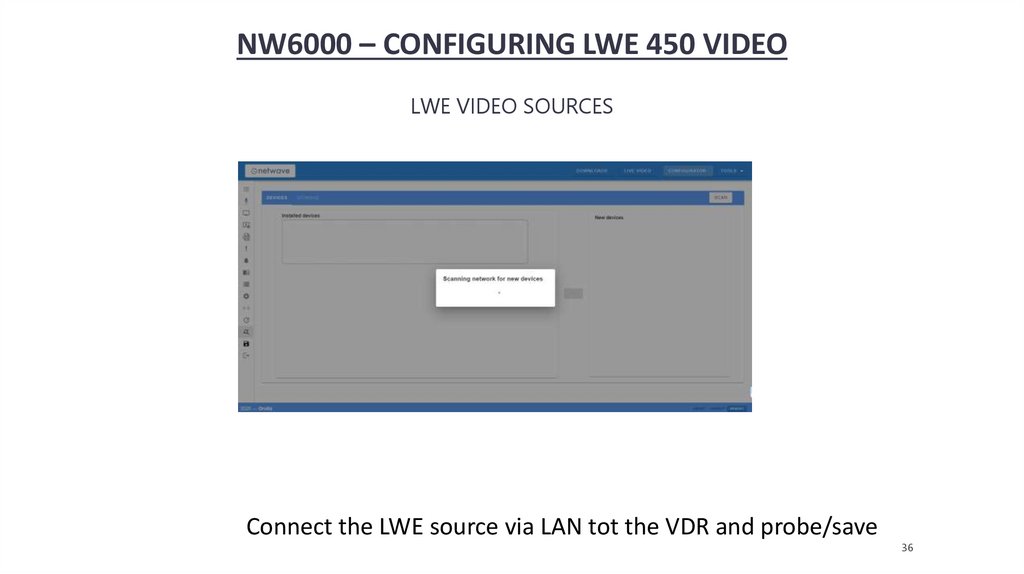
NW6000 – CONFIGURING LWE 450 VIDEOLWE VIDEO SOURCES
Connect the LWE source via LAN tot the VDR and probe/save
36
37.
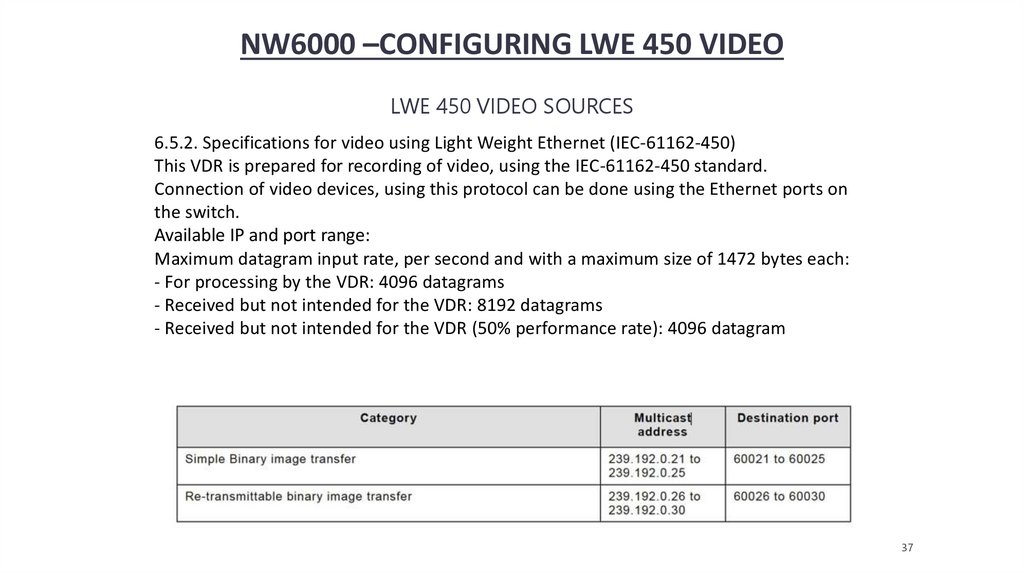
NW6000 –CONFIGURING LWE 450 VIDEOLWE 450 VIDEO SOURCES
6.5.2. Specifications for video using Light Weight Ethernet (IEC-61162-450)
This VDR is prepared for recording of video, using the IEC-61162-450 standard.
Connection of video devices, using this protocol can be done using the Ethernet ports on
the switch.
Available IP and port range:
Maximum datagram input rate, per second and with a maximum size of 1472 bytes each:
- For processing by the VDR: 4096 datagrams
- Received but not intended for the VDR: 8192 datagrams
- Received but not intended for the VDR (50% performance rate): 4096 datagram
37
38.
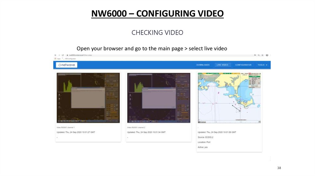
NW6000 – CONFIGURING VIDEOCHECKING VIDEO
Open your browser and go to the main page > select live video
38
39.
QUESTIONS?39