


")


 Электроника
 Промышленность
Похожие презентации:


Line protection
1. LINE PROTECTION
2.
TRANSMISSION LINE PROTECTIONTransmission lines can vary in length from several hundred feet to several
hundred miles, and in voltage (line-to-line) from 46KV to 750KV.
Construction can be simple, such as a single wood pole with insulators atop
a crossarm, with little spacing between the conductors and from the
conductors to ground. At the other end of the scale are metal lattice
structures with bundled conductors (2 or more conductors per phase) with
large spacing between conductors and between conductors and ground.
3. Faults
“Faults come uninvited and seldom go away voluntarily.”Fault Types:
●Single line-to-ground
Line-to-line
Three Phase
Line-to-line-to-ground
4. HOW DO WE DO PROTECT Transmission Lines?
OvercurrentDirectional overcurrent
Distance
Pilot
Line Current Differential
5. Assignment of relay protection of power transmission line
In the event of damage to the insulation of the cable anywhere orextended overhead line voltage is applied to the line creates a
leakage current or a short circuit through the broken section.
The causes insulation failure can be a variety of factors that can
exclude himself or to continue their devastating effects. For
example, flying between the wires overhead line Stork created a
phase to phase fault with their wings and burned, falling nearby.
6.
For these reasons, all resulting damage to powerlines must be immediately eliminated. This is
achieved by removing the voltage from the
damaged line on the supply side. If such a
transmission line is powered from both sides,
they both have to turn off the voltage.
Features continuous monitoring of the electrical
parameters of the status of all power lines and
removing them from the stress from all sides in
the event of any emergency situations are
assigned to the complex technical systems,
which are called by tradition relaying.
The adjective "relay" is derived from the
element base on the basis of the electromagnetic
relay, the design of which arose with the advent
of the first transmission lines and improved to
this day.
7. Principles of relay protection Supervision network status
To monitor the electrical parameters of power lines need to have bodies of theiroftorelay
protection
measurements,Principles
which are able
continuously
monitor all of the normal mode
rejection in the Supervision
network and at the
same time
meet the requirements for safe
network
status
operation.
The power lines of all voltages, this function is assigned to the measuring
transformers. They are divided into transformers:
• Current (CURRENT TRANSFORMERS);
• voltage (VOLTAGE TRANSFORMERS).
Since the quality of protection is of paramount importance for the reliability of
the electrical system, by measuring current and voltage transformers are
increased requirements for accuracy of which are determined by their
metrological characteristics.
Accuracy classes of measuring transformers for use in devices RZA (relay
protection and automation) are normalized values of "0.5", "0.2" and "P".
8. MEASURING TRANSFORMERS
VOLTAGE TRANSFORMERCURRENT TRANSFORMER
9. Processing the information received organs
In relaying the main operating element is a switch - electrical device thatperforms two main functions:
• monitors the quality of the controlled parameter, such as current and
normally supports stable and does not change the state of its contact system;
• If a critical value, called the set point or the minimum threshold, instantly
switches the position of the contacts and in this state as long as the
monitoring value will not return to normal values.
The principles of the relay switching schemes of current and voltage in the
secondary circuit helps to understand representation of sinusoidal harmonic
vector quantities with the image of the complex plane.
10. Examples of expressions of sinusoidal harmonics of the vector unit circle
11. Resistance line control methods
relay protection devices, estimating the distance to the shortcircuit has arisen on the basis of measuring the electrical
resistance, called spacers or abbreviated DMZ defenses. They are
also used in the work circuit current and voltage transformers.
To measure the resistance of the expression is used Ohm's Law,
described for the section of the circuit concerned.
When passing through the active sinusoidal current, capacitive
and inductive impedance vector of the voltage drop across them
is deflected in different directions. It takes into account the
behavior of relay protection.
12. BEHAVIOUR current vector and the voltage on various kinds RESISTANCE
According to thisprinciple, many types
of resistance relay
(RS) working in
relay protection and
automation devices.
13. Basic protection of high-voltage lines (differential-phase protection type DFP-201)
Basic protection of high-voltage lines (differentialphase protection type DFP-201)Differential - phase protection type DFP-201 is used as the main protection of
overhead transmission lines with voltage of 110 - 220 kW, which is necessary to
disable all kinds of damage without delay short-circuit at any point of the
protected line.
The basis of the protection actions laid differential principle or the comparison
phase currents at opposite ends of the line. Unlike conventional differential
protection, diffaznye protection can protect objects much greater extent
(hundreds of kilometers).
Protection provides information on the current direction of the object to an
object at a high frequency (usually) channel, the main element of which is a
transmission line. Some transceivers have a modification for communication
over fiber - optic lines (FOL), but widespread, they have not yet received, why
restrict ourselves to the high-frequency (HF) communication channels and their
elements.
14.
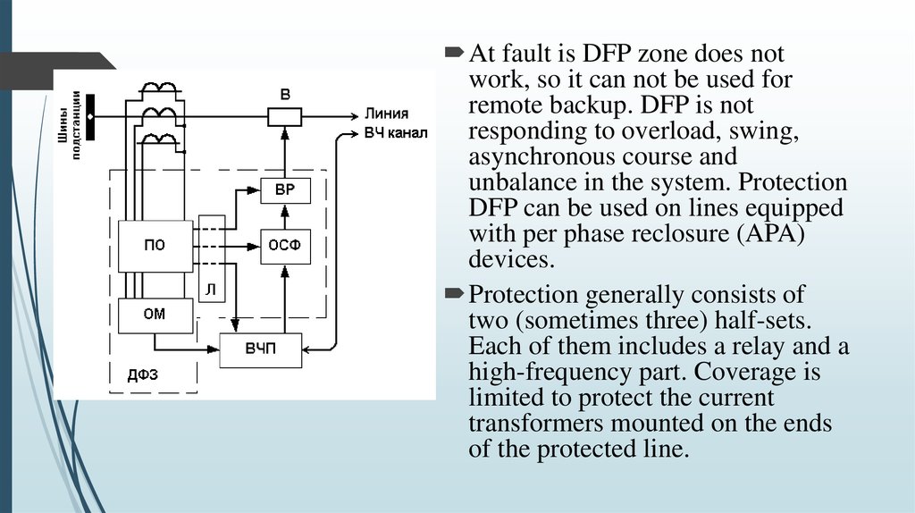
At fault is DFP zone does notwork, so it can not be used for
remote backup. DFP is not
responding to overload, swing,
asynchronous course and
unbalance in the system. Protection
DFP can be used on lines equipped
with per phase reclosure (APA)
devices.
Protection generally consists of
two (sometimes three) half-sets.
Each of them includes a relay and a
high-frequency part. Coverage is
limited to protect the current
transformers mounted on the ends
of the protected line.
15.
Starting authority starts the transmitter with the appearance of faults in thenetwork environment.
The organ manipulation controls the parameters of the RF signal generated
by the transmitter.
comparing the current phase Authority (CSFs), according to information
received from the receiver determines the short circuit: in the protection of
coverage area or beyond.
The output relay acts on the circuit breaker (B)
The logical part of the protection on the information obtained from the
starting body, forms a team to start the RF transmitter, the preparation phase
comparison authority to act on the trip and prepares relay output circuit.
16. Diagram illustrating the operation of the protection in case of short circuit in the action zone and outside it, is given
below:The presence of the signal at the transmitter output is
determined by the control signals coming from any part
of relay protection in the event of abnormal network
conditions, or from CDV controls.
When the transmitter does not work (protection is in
standby mode) and the receivers do not accept, at the
output of receivers takes a direct current a certain value
(10 mA or 20 mA), called the current peace. When this
electromotive force in a secondary winding of the
transformer body phase comparison is not induced, as
the magnetic flux is not changed in its core. The current
in the phase comparison relays body (WP4-2) is zero.
17.
If a short circuit in the protection range (to protect the line A - B) positivehalf cycle I1 + kI2 conditional current half-sets AB (substation A line in the
direction of the substation B) and BA coincide (Figures A1 and B1). Positive
(or negative depending on the type of HF post) half-cycle current
corresponds to the emergence of high-frequency pulse output UVCHP RF
transmitter (c1). Pulses on Ui Rx receiver input from its own transmitter and
received from the opposite end of the line are the same or close to the phase
(G1). In the absence of receiver Ilim equal to 20 mA current output signal
(in some cases - 10 mA), and falls to zero (e1) when a signal. Intermittent
reception current through phase comparison transformer body is converted
into a pulsating current in the relay coil 2-WP4 (IPR4 e1 diagram).
When faults outside the protection coverage (protection line B - B) positive
half cycle of the current conditional shifted by about 180 ° (a2, b2). The
pulses at the receiver from its own transmitter and received at the opposite
end of the line are in antiphase (r2). Receiving current and the coil current is
zero 2-4PR (d2, e2).
18. References
http://dororz.ru/http://electricalschool.info/relay/1647-kak-ustroenarelejjnaja-zashhita-linijj.html