


 Программное обеспечение
Похожие презентации:
")


 Mode. (Lecture 11)")
")


: MS.NET")

Analysis and Design of Data Systems. Entity Relationship Model. (Lecture 8)
1.
IE301Analysis and Design of Data Systems
Lecture 8
Entity Relationship Model
Aram Keryan
September 23, 2015
2. Phases of Database Design
MiniworldRelational
DBMS
Requirements
Collection and
Analysis
Conceptual
Design
Relational
Database
Schema
3. Phases of Database Design
MiniworldRelational
DBMS
Requirements
Collection and
Analysis
Conceptual
Design
Relational
Database
Schema
We are here
4. Requirements Collection and Analysis
During this stage database designers interview prospectivedatabase users to understand and document their data
requirements
Example of data requirements for Company database:
Company consists of five departments
Department is identified by department number and name
Employee can work for only one department
Each employee may have a supervisor who is also an employee
Department controls a number of projects
Employee can work on several projects
Employees are payed on hourly basis
And so on . . .
5. Conceptual Database Design
Conceptual database design involves modelling thecollected information at a high-level of abstraction without
using a particular data model or DBMS.
Reasons for Conceptual Modelling:
• Independent of DBMS
• Allows for easy communication between end-users and
developers
• Has a clear method to convert from high-level model to
relational model
• Conceptual schema is a permanent description of the
database requirements
6. Conceptual Database Schema
As a result of using High-Level Conceptual Data Model aConceptual Database Schema is created
Conceptual Schema includes detailed description of the
entity types, relationships, and constraints
Conceptual Schema reflects all the data requirements
collected during the initial stage
7. Entity-Relationship Model
8. Entity-Relationship Model
Entity-Relationship diagram models data as entities,attributes and relationships
is a thing about which we store data
Entity
is a thing in the real world with independent existence
is a thing which can be distinctly identified
e.g. a person, a bank account, a building
Entity is a basic object that ER model represents
9. Examples of Entities Types
• Examples of a person entity would be EMPLOYEE, DOCTOR, orSTUDENT
• Examples of a place entity would be STATE or COUNTRY
• Examples of an object entity would be BUILDING, AUTO, or
PRODUCT
• An example of an event entity would be SALES, RETURNS, or
REGISTRATION
• An example of a concept entity would be ACCOUNT or
DEPARTMENT, UNIVERSITY COURSE
10. Attributes
Each entity type has attributes — the particular propertiesthat describe it
e.g., EMPLOYEE entity type may be described
by the employee’s name, age, address, salary,
and job
Address
Attribute
Attribute
Attribute
ENTITY
Name
Salary
Job
Age
EMPLOYEE
11. Entity Types and Entity Sets
An entity type defines a collection (or set) of entities thathave the same attributes.
Each entity type is described by its name and attributes
An entity set is the collection of all entities of a particular
entity type in the database at any point in time
Entity sets usually have the same name as entity types
Entity Type
Entity Set
Model
Make
Year
CAR
(Toyota, Camry, 2005)
(Toyota, Yaris, 2009)
(Nissan, Skyline, 2010)
(Porsche, Cayenne, 2006)
…………………..
12. Types of Attributes
Several types of attributes occur in the ER model:simple (atomic) versus composite
Single-valued versus multi-valued
stored versus derived
13. Simple vs. Composite Attributes
StateSalary
Name
Address
Street_
address
Job
City
Age
EMPLOYEE
Apartment
_number
Street
Number
Zip
“Address” is a composite attribute – it can be divided into smaller
subparts representing more basic attributes with independent meaning.
Simple or atomic attributes are not divisible.
14. Another example of a composite attribute
15. Single-valued vs. multivalued attributes
An attribute can have a set of values for the same entityModel
Degree
Color
Year
Make
Address
Name
B.date
CAR
STUDENT
Car can be of one color or can
be of multi-color
A student can have one or
several degrees
16. Stored vs. Derived Attributes
AgeAddress
Name
B.date
STUDENT
I some cases, two (or more)
attribute values are related
“Age” and “B.date” are related since for a particular student his/her
age can be determined from the current date and his/her birth date.
“Age” is called a derived attribute
“B.date” is called a stored attribute
17. Key Attributes
Entity types usually have one or more attributes whose valuesare distinct for each individual entity in the entity set
Such an attribute is called a key attribute, and its values can be
used to identify each entity uniquely
18. Example: Requirements Collection and Analysis “COMPANY”
An entity type DEPARTMENT with attributes Name, Number,Locations, Manager, and Manager_start_date. Locations is the only
multivalued attribute. We can specify that both Name and Number
are (separate) key attributes because each was specified to be
unique.
19. Example: Requirements Collection and Analysis “COMPANY”
An entity type PROJECT with attributes Name, Number, Location,and Controlling_department. Both Name and Number are
(separate) key attributes.
20. Example: Requirements Collection and Analysis “COMPANY”
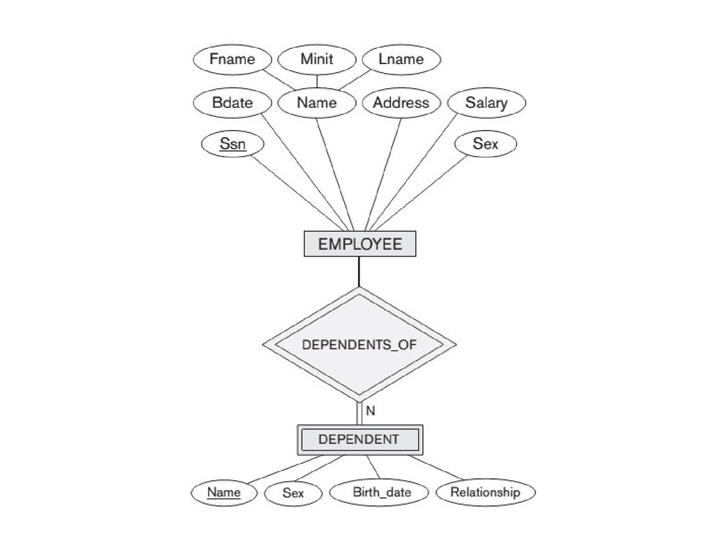
An entity type EMPLOYEE with attributes Name, Ssn, Sex, Address, Salary,Birth_date, Department, and Supervisor. Both Name and Address may be
composite attributes; however, this was not specified in the requirements.
We must go back to the users to see if any of them will refer to the individual
components of Name—First_name, Middle_initial, Last_name—or of Address. In
our example, Name is modeled as a composite attribute, whereas Address is
not, presumably after consultation with the users.
21. Example: Requirements Collection and Analysis “COMPANY”
An entity type DEPENDENT with attributes Employee,Dependent_name, Sex, Birth_date, and Relationship (to the
employee).
22. Identifying Relationships
Whenever an attribute of one entity type refers to anotherentity type, some relationship exists.
23. Understanding Relationships
Roleemployee
worker
Role
department
employer
Role name signifies the role that a participating entity from the
entity type plays in each relationship instance, and helps to explain
what the relationship means.
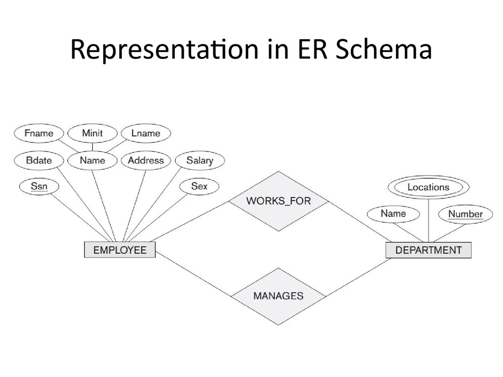
24.
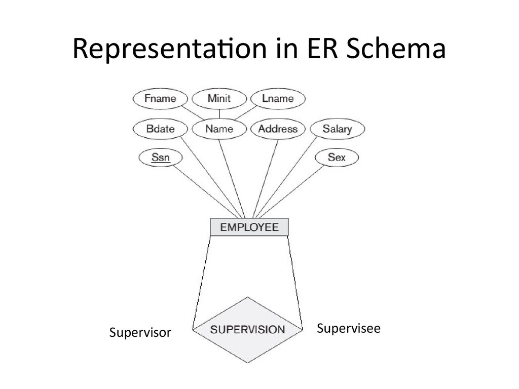
Representation in ER Schema25. Recursive Relationships
In some cases an entity typeparticipates more then once in
a relationship in different roles
EMPLOYEE
Such relationships are
called recursive
Each instance of
EMPLOYEE type plays one
of two roles:
supervisor(1) or
employee (2)
26.
Representation in ER SchemaSupervisor
Supervisee
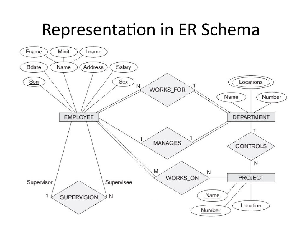
27. Degree of a Relationship
The degree of a relationship is the number of participatingentity types
WORKS_FOR
ralationship is of
degree two
A relationship type
of degree two is
called binary
28. Degree of a Relationship
SUPPLY ralationshipis of degree three
A relationship type
of degree three is
called ternary
If N entity types participate
in a relationship then such
relationship is of degree N
29. Constraints on Binary Realtionships
Two main types of binary relationship constraints:Cardinaliry Ratio
and
Participation
Structural Constraints
These constraints are determined from the miniworld situation
that the relationships represent
30. Cardinality Ratios for Binary Relationships
The cardinality ratio for a binary relationship specifies themaximum number of relationship instances that an entity can
participate in (determined from the Miniworld situation)
For WORKS_FOR relationship
DEPARTMENTE : EMPLOYEE
cardinality ratio is 1:N
Possible cardinality ratios
for binary relationships
are:
• 1:1 (one to one)
• 1:N (one to many)
• M:N (many to many)
31. Example of 1:1 relationship
Miniworld rules• Employee can manage one department only
• Department can have one manager only
32. Example of M:N relationship
Miniworld rules• Employee can work on several projects
• Project can have several employees
33.
Representation in ER Schema34. Participation constraints
Participation constraint specifies the minimum number ofrelationship instances that each entity can participate in
There are two types of participation constraints—total and partial
Participation of DEPARTMENT
in MANAGES is called total
participation, meaning that
every department must be
managed by one employee.
Participation of EMPLOYEE in
MANAGES is called partial
participation, meaning that a
employee may or may not be a
manager of a department.
35.
Representation in ER Schema36. Attributes of Relationships
37. Weak Entity Types
Entity types that do not have key attributes of their own arecalled weak entity types
In contrast, those entity types that do have a key attribute are
called strong entity types
A weak entity type always has a total participation constraint with respect to
its identifying relationship because a weak entity cannot be identified
without an owner entity
A weak entity type normally has a partial key, which is the attribute that can
uniquely identify weak entities that are related to the same owner entity