


 Промышленность
Похожие презентации:


Trouble Shooting Guide <Hardware Issues>
1.
bizhub C360 / C280 / C220Trouble Shooting Guide
<Hardware Issues>
Ver. 2.0
Office Printing Support Division
CS Operations
Konica Minolta Business Technologies, Inc.
2.
Contents* Blue colored items are new from previous version
<Operation/Display issue>
<Image issue>
1. Color reproduction when copying cloth
2. FD White Line (PH)
3. Waving image
4. Spot on Drum Unit
5. FD White line (Drum)
6. Noise Image (High Voltage Board)
7. Gradation Adjustment
8. Image Failure on the leading edge
9. Abnormal Image(P-5,P-28,P-21)
10. Slanting Image(Black)
11.Only Bk color was not printed out
(P9/P21 displayed) upon installation
12. Image quality problem caused by
MFP board
<Paper transportation issue>
13. Thick paper Jam on Tray1
14. 1st Tray Paper Jam (J1144)
15. Wrinkles on Envelope
16. Paper Jam in paper exit section (J3205)-1
17. Paper Jam in paper exit section (J3205)-2
18. Display “Paper Jam” on the additional
cassette
19. Damage of the punched holes
<ADF issue>
20. DF-617 Detection Failure
21. DF-617 Skew of Original Paper
22. The abnormal noise occur while feeding original
with DF-617
23 Occurring C-8106 because of detection error of
Lifting Plate
24. Original misfeed (J6602) in the DF (1)
25. Original misfeed (J6602) in the DF (2)
<Finisher issue>
26. Stapling failure with FS-529 (1)
27. Stapling failure with FS-529 (2)
28. Stapling failure with FS-529 (3)
29. C-1191 with FS-529
30.FS-529 Operating noise when moving exit tray
31. Detection Failure of JS-505/FS-527
32. JAM Problem in FS-529 (J72-17)
33. FS-529 C-1183
34. JAM (72-87) occurs in the Center Staple &
Fold mode on SD-509
35. Wrong Booklet Tray Full Detection on SD-509
36. Paper alignment failure on FS-527
37. Operational noise from JS-504/505
<Trouble code issue>
38. C-5501 (AC signal abnormality)
39. C-B001
40. C-B003
41.C-2253/C-5102(DCPU failure)
42. J14-01 when setting up PC-207
43. Custom size is returned to Auto
detection
44. Detection failure of “Toner near empty”
45.“Front door open” is detected
46.Broken NVRAM connector
47. Machine does not boot up
48. Trouble with Std. DIMM
49. Message on the panel
<Abnormal noise issue>
50. Abnormal noise in the fuser pressure
release motor
51. Noise from neutralization brush
52. Noise from DCPU
53. Sound occurs when feeding Thick paper
54. Relay on DCPU chattering when turning
ON main SW
55. Noise occurs when feeding paper in ADU
56. Abnormal Noise from the scanner section
<Others>
57. Tray comes out
58. Tearing off Neutralizing brush from Cover
Output
59. Cable Cover cannot be closed completely
60. 2nd paper feeding guide is broken
61. Actuator detecting paper JAM at exit section
is broken
62.Left side cover can’t be replaced
3.
1. Color reproduction when copying cloth【 Symptom 】
When copying cloth as an original, the printed color becomes reddish.
【 Cause 】
This symptom occurs when a specific cloth is used.
When a specific type of cloth that reflects infrared rays is used, the infrared area will be read as
more reddish than the original.
【 Countermeasure 】
There is no countermeasure on this series.
In order to improve this symptom, it is necessary to change the lens to a type that has the ability
to cut the infrared rays. The parameter of the image processing also needs to be modified.
【 Action in the field 】
N/A
4.
2. FD White Line (PH)【 Symptom 】
White line (FD) occurs on the halftone image.
【 Cause 】
The dust is stuck on the window of PH.
In the production line, the cleaning stick (pad) was
damaged when the PH was installed to main body, then,
the dust was attached on the cleaning pad.
【 Countermeasure 】
The checking process on the production line was
improved.
【 Action in the field 】
1. Cleaning the PH by using the cleaning stick.
2. If FD line cannot be solved by step above (1), please
clean up the window of the PH by removing PH unit. At
the same time check whether the cleaning pad is broken.
5.
3. Waving image【 Symptom 】
The waving image may occur in FD (Feeding
Direction).
【 Cause 】
The rotation of the polygon motor is not stable.
This is caused by the fixing failure of a GND
screw which should be fixed on the polygon
motor board in the PH.
【 Countermeasure 】
Improved the inspection process of above
operation on production line.
【 Action in the field 】
Replace the whole PH unit.
6.
4. Spot on Drum Unit (1/2)【 Symptom 】
The drum damage (spot) may occur at the
machine installation.
【 Cause 】
The operator/CE makes a mistake in the
installation.
If the drum unit is installed without removing
the protection material, there is the possibility
of damaging the surface of the drum unit by
touching the DS roller.
7.
4. Spot on Drum Unit (2/2)Before
After
【 Countermeasure 】
The design of the protection material will be changed to a “foolproof” design. (*Please see the
above pictures for details.)
【 Action in the field 】
Proceed with the installation by carefully referring to the installation manual.
【 Ref. 】
TAD No. TABT0900207****
8.
5. FD White line (Drum)【 Symptom 】
White line (FD) occurs.
【 Cause 】
The main reason could not be found. Although one of the reasons considered was dirt
on the electric charger of the drum.
【 Countermeasure 】
N/A
【 Action in the field 】
1. Cleaning the electric charger by the cleaning stick.
2. If the white line cannot be corrected by the above step (1), replace the Drum Unit.
9.
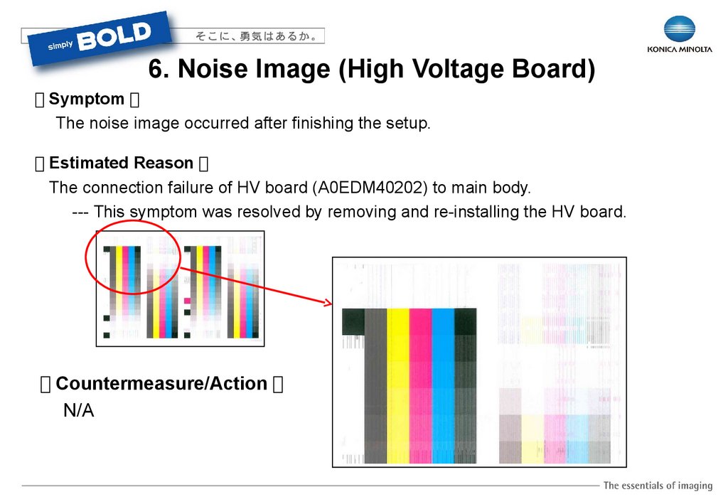
6. Noise Image (High Voltage Board)【 Symptom 】
The noise image occurred after finishing the setup.
【 Estimated Reason 】
The connection failure of HV board (A0EDM40202) to main body.
--- This symptom was resolved by removing and re-installing the HV board.
【 Countermeasure/Action 】
N/A
10.
7. Gradation Adjustment (1/2)【 Symptom 】
FEET (rear edge side) of gradation adjustment output looks abnormal. It is different with
color tone or gradation adjustment.
【 Cause 】
FEET gradation adjustment is the image processing mainly applied to the edge parts of letters. It is
comparably difficult to converge the targeted gradation as this mode has less gradation steps. So this
image is specification.
【 Action in the field 】
Basically you do not need to worry about the convergence value for the gradation adjustment of
FEET. However, if the gradation adjustment falls a long way outside of the following range, you
must conduct a gradation adjustment again after performing “Initialization and Stabilization”.
Convergence at high density part within +/- 100
Convergence at low density part within +/- 60
【 Other information 】
TAD No. TABT1000141****
11.
7. Gradation Adjustment 2/2Gradation adjustment
FEET
12.
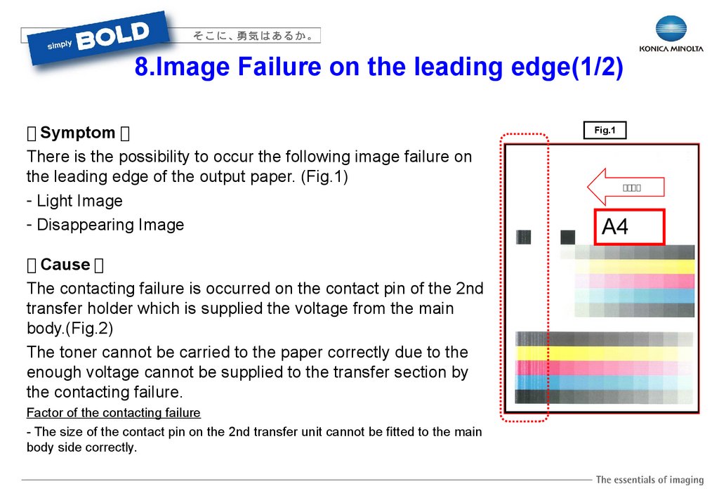
8.Image Failure on the leading edge(1/2)【 Symptom 】
There is the possibility to occur the following image failure on
the leading edge of the output paper. (Fig.1)
- Light Image
- Disappearing Image
【 Cause 】
The contacting failure is occurred on the contact pin of the 2nd
transfer holder which is supplied the voltage from the main
body.(Fig.2)
The toner cannot be carried to the paper correctly due to the
enough voltage cannot be supplied to the transfer section by
the contacting failure.
Factor of the contacting failure
- The size of the contact pin on the 2nd transfer unit cannot be fitted to the main
body side correctly.
Fig.1
給紙方向
A4
13.
8.Image Failure on the leading edge(1/2)【 Action in the field 】
Please adjust the scale(2 scales) of the vertical
transportation inner door to the right side from the
center position(Fig.3), if the same image failure
occurs.
Please refer to TAD which mentions the instruction
how to adjust the scale in details.
【 Permanent Countermeasure 】
The design of the length of the contact pin was
changed in order to keep the enough contact
stroke to the main body.
【 Reference 】
TAD No. TABT1000781EN01
Fig.2
Contact Pin
Fig.3
14.
9.Abnormal Image(P-5,P-28,P-21)【 Symptom 】
The abnormal image is printed out. (Fig.1)
The warning code of P-5, P-28, P21 are indicated.
Fig.1
Normal
【 Cause 】
IDC sensor failure.
【 Action in the field 】
Replace the IDC sensor Assy, if the image failure
cannot be solved by proceeding the following action.
Abnormal
【 Estimated reason 】
1.Flat cable (Disconnect – connect or Replace)
2.PH (Replace)
3.MFP board (Replace)
4.PRCB board (Replace)
15.
10.Slanting image(Black)Fig.1
【 Symptom 】
The slanting image is printed out in a short time after installing the main body.
(Fig.1)
【 Cause 】
No or a few black developer in the developing unit.(Fig.2)
There is the possibility that the black developer is dumped into the waste
toner box by the vibration during the shipment of the brand new machine
with the long distance by the track.
【 Action in the field 】
- Replace the developing unit(Bk), if the same symptom
will be found at the machine installation.
- Proceed the “Manual Toner Add” from the service
mode.
【 Action in the field 】
Under the consideration.
Fig.2
No developer(Bk) on the
developing roller in the brand
new condition.
16.
11.Only Bk color was not printed out(P9/P21 displayed)upon installation
【 Phenomenon 】
P9 and P21 were displayed after turn on the main SW and only Black color was not
printed out.
【 Cause 】
Bad electrical contact between CN5PH
and PWB-PH ASSY.
【 Action in the field 】
Replace the Flat cable.
17.
12. Image quality problem caused by MFP board (1/2)【 Symptom 】
Image quality problem occurs caused by MFP board.
【 Cause 】
MFP board failure.
【 Action in the field 】
Check Trouble Shooting on service manual first when image quality problem occurs.
If the problem can’t be fixed, replace MFP board.
Case 1
Case 2
17
18.
12. Image quality problem caused by MFP board (2/2)Case 3
Case 4
Original
18
19.
13. (1) Thick paper Jam on Tray1(2) Paper Jam (with plain paper) on Vertical Transport section
【 Symptom 】
1. When Thick paper is fed from Tray1, the edge of
the paper will be caught on the edge of the transport
guide, and paper jam occurs. [JAM code: J11XX]
2. When plain paper is fed from Tray2,3,4, the edge of
the paper will be caught on the edge of the transport
guide, and paper jam occurs. [JAM code : J20XX]
【 Cause 】
There are possibilities that the following types of
failure are produced on the holder (transport).
P/N A0ED7010
- bump (refer to the right picture)
- burr
【 Countermeasure 】
Modified the mold.
【 Action in the field 】
If the above symptom occurs, clean up the “bump” or
“burr” on holder (transport) by using sand paper.
bump
【 Other information 】
TAD No. TABT1000113****
20.
14. 1st Tray Paper Jam (J1144)【 Symptom 】
Paper Jam occurs in the paper feed section of 1st Tray. [JAM code : J1144]
【 Cause 】
The JAM detection timing have not enough allowance , when the paper feed slipping is
large.
【 Countermeasure 】
Even if the sensor in front of tim. Roller (PS1) is turned on when the judging to retry 1st and
bypass paper feed, paper transportation is continued without stopping jam(J1144/J1044).
【 Action in the field 】
[Download file name]
A0ED0Y0-F000-GC7-B4.EXE
Program Name:Printer “A0ED0Y0-0050-G10-05” or later
【 Other information 】
TAD No. TABT1000404****
21.
15. Wrinkles on Envelope (2/2)Spring for envelope
Spring for plain paper
Envelope
Plain Paper
【 Countermeasure 】
Increasing the clearance of fusing roller pressure mechanism and decreasing the fusing
pressure for Envelope by changing the motor pulse.
【 Action in the field 】
Update the firmware to the following version when the above symptom occurs.
DLBT1001593**** Ver. A0ED0Y0-0050-G10-04
22.
16. Paper Jam in paper exit section(J3205) (1/2)【 Symptom 】
Accordion paper jam is occurred in the paper exit section. [JAM code: J3205]
<Occurrence condition>
Paper Jam at the Fusing Unit is likely to be occurred on the following conditions.
The paper that rigidity is weak.
High humidity.
Immediately after warm-up.
(1) Fusing guide / exit roller (2)Exit guide
【 Cause 】
Cause①
The rigidity of paper decreases with the moisture uptake.
The buckling distortion of paper is occurred by "sliding resistance with the guide and bump' at
transportation route.
Cause②
23.
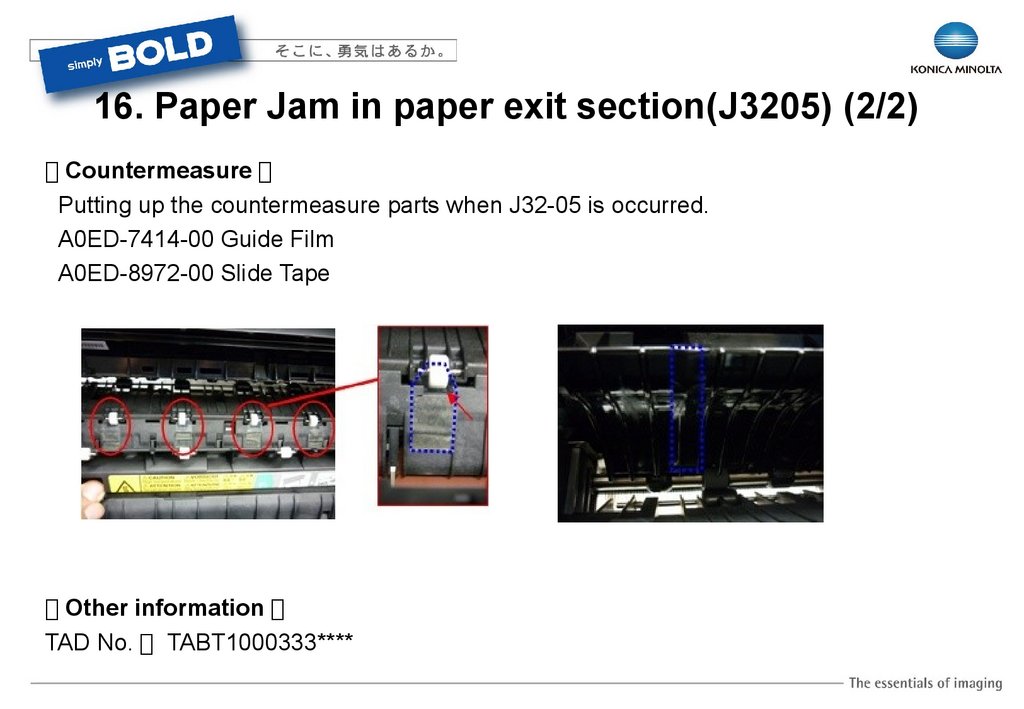
16. Paper Jam in paper exit section(J3205) (2/2)【 Countermeasure 】
Putting up the countermeasure parts when J32-05 is occurred.
A0ED-7414-00 Guide Film
A0ED-8972-00 Slide Tape
Guide Film (4 pieces)
【 Other information 】
TAD No. TABT1000333****
Slide Tape (2 pieces)
24.
17. Paper Jam in paper exit section (J3205) (2) (1/2)【 Contents of change for mass-production 】
• The Guide Film has been added to the Fusing Unit.
A0ED741400 : Guide Film
• Due to the Guide Film added, the item code of the Fusing Unit has been changed.
A0EDR72011 -> A0EDR72022 : Fuser unit(120V)
A0EDR72111 -> A0EDR72122 : Fuser unit(200V)
A0EDR73811 -> A0EDR73822 : Fuser unit(110V)
• The shape of the ribs of the Guide has been changed as next page. (4-parts)
A0ED890401 -> A0ED890402 : Guide
【 Applied Machine Serial Number 】
Refer to PMN No. KOM101179
25.
17. Paper Jam in paper exit section (J3205) (2) (2/2)【 Ref. 】
TAD No.: TABT1000333EN01
PMN No. KOM101179
26.
18. Display “Paper Jam” on the additional cassette【 Symptom 】
After machine is turned ON, the “Remained Paper Jam” may be detected on Tray3, or Tray4.
【 Cause 】
The reason is the timing of the initial communication between main body and optional
cassette when turning on. It takes 16.6 ms to complete the initializing communication and
sensor checking, then, if the door is opened by any action during initializing, there is
possibility that the detection of remained paper will be detected.
【 Countermeasure 】
Modified the completing time of the initial communication and sensor checking.
【 Action in the field 】
Update the firmware to v.88 or later.
27.
19. Damage of the punched holes (1/2)【 Symptom 】
When the original paper which has 4 punched holes is scanned as double sided, these holes may
be damaged.
【 Cause 】
When the original is inversed by the inversing roller, the punched holes are scratched by the PET
mylar. (P/No: A0HT-7060-00).
【 Countermeasure 】
Modified the type of PET mylar. (P/No: A0HT-7060-01)
Applied Machine Number
A0HUWY1117557 and onward
【 Action in the field 】
Remove the 4 pcs of PET mylars. The purpose of these mylars is to improve the paper feeding
when an original of A5 will be fed by SEF only.
【 Other information 】
TAD No.: TABT0900189****
PMN No.: KOM100901**
28.
19. Damage of the punched holes (2/2)Old P/No.:
A0HT-7060-00
4pcs
New P/No.:
A0HT-7060-01
8pcs
29.
20.DF-617 Detection Failure【 Symptom 】
Fig.1
DF-617 detection failure is occurred at installation.
DF-617 cannot be detected by main body.
“The document size cannot be detected. Remove the document, ….” is
displayed w/o the original paper on the document feeder. (Fig.1)
【 Cause 】
The bend of the terminal pin(Fig.2) in the ADF connector causes
the contacting failure.
Factor of the bend on the terminal pin
When ADF connector is inserted to the main body obliquely, the
connector pin is bent with by the burr in interference.
【 Action in the field 】
Insert the ADF connector straight in the installation.
Adjust the height of the terminal pin to the correct position, if the bend of the
terminal pin is found.
【 Permanent Countermeasure 】
The mold for ADF connector which prevents the burr was changed from
Oct/2010.
Fig.2
30.
21.DF-617 Skew of Original Paper【 Symptom 】
When the original paper is fed in the duplex mode, there is the possibility
that the scanned image on the 2nd side is skewed or a part of image is
defected. (Fig.1)
Fig.1
【 Cause 】
The pressure of the plate spring which presses the roller(Fig.2) is stronger than
the standard, so, the original paper is skewed to the rear side direction.
【 Action in the field 】
Adjust the pressure level of the plate spring to the upper direction(Red
arrow) which makes the decreasing of the pressure.(Fig.3)
【 Permanent Countermeasure 】
The plate spring was changed
from the mass-production of
Sep.2010.
Fig.3
Fig.2
31.
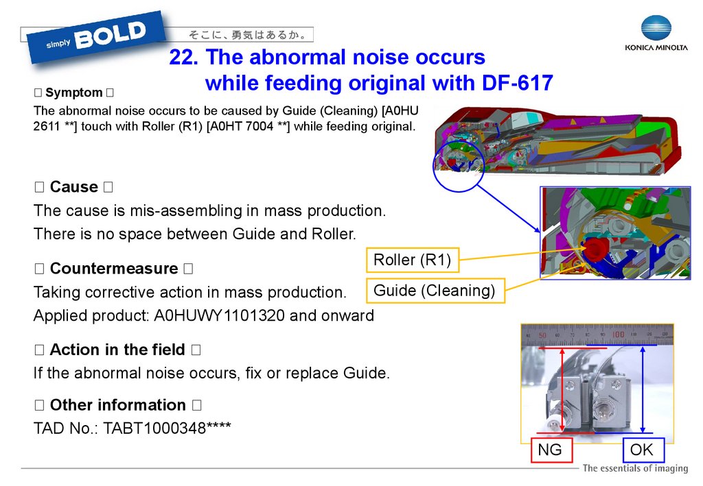
22. The abnormal noise occurswhile feeding original with DF-617
【 Symptom 】
The abnormal noise occurs to be caused by Guide (Cleaning) [A0HU
2611 **] touch with Roller (R1) [A0HT 7004 **] while feeding original.
【 Cause 】
The cause is mis-assembling in mass production.
There is no space between Guide and Roller.
Roller (R1)
【 Countermeasure 】
Guide (Cleaning)
Taking corrective action in mass production.
Applied product: A0HUWY1101320 and onward
【 Action in the field 】
If the abnormal noise occurs, fix or replace Guide.
【 Other information 】
TAD No.: TABT1000348****
NG
OK
32.
23. Occurring C-8106because of detection error of Lifting Plate
【 Symptom 】
C8106 Lift up mechanism trouble (Downward movement) occurs.
【 Cause 】
Light blocking plate [A01H 5601 **] of lifting plate [A01H 5607 **] doesn't down to detecting
position of the sensor [A108 M501 00], because of bracket interfere with the rib of tray.
【 Countermeasure 】
Cutting the rib interfering with bracket of tray [A01H 5601 **]
Applied product: A0HUWY1134643 and onward
【 Action in the field 】
Attach modified part [A0HU P560 00] to light blocking
plate of Lifting Plate [A01H 5607 **].
【 Other information 】
TAD No.: TABT1000344****
PMN No.: KOM101282**
33.
24.Original misfeed (J6602) in the DF(1) (1/3)
【 Symptom 】
There is a possibility that the original misfeed (J6602) occurs on the DF.
【 Object product 】
DF-619 (C652DS/C552DS)
DF-618 (C652/552/452)
DF-617 (C360/280/220)
【 Cause 】
There was a small burr on the paper guide on the Upper Cover, the leading edge of
paper is stopped before the separation rollers. The burr is a parting line of the
molding.
34.
24.Original misfeed (J6602) in the DF (1/2)【 Symptom 】
There is a possibility that the original misfeed (J6602) occurs on the DF.
【 Object product 】
DF-619 (C652DS/C552DS)
DF-618 (C652/552/452)
DF-617 (C360/280/220)
【 Cause 】
There was a small burr on
the paper guide on the
Upper Cover, the leading
edge of paper is stopped
before the separation
rollers. The burr is a
parting line of the molding.
Cover Upper
A0HT5608
Rear side
Burr on the parting line
Front side
No burr on this side
35.
24.Original misfeed (J6602) in the DF (2/2)【 Action in the field 】
File the burr with sandpaper (ISO Grit size P1000 to P1200).
File the burr by sandpaper on the direction of red arrow.
File the burr by sandpaper on
the direction of red arrow.
Note: Do not file the burr too much because the burr is on the paper guide.
【 Reference 】 TABT1000347EN01
【 Effective Se/No. 】 PMN KOM101105
36.
25.Original misfeed (J6602) in the DF(2) (1/2)【 Symptom 】
ADF paper feed section Jam for DF-617 (J66-02) .
【 Cause 】
The separator pad peeled off.
There was a case defect the spare parts as well.
A01HR70400 : Separator pad ASSY
There is a possibility that the following problems may
occur.
Original Jam , Skew and Damage in front edge of
the original.
37.
25.Original misfeed (J6602) in the DF(2) (2/2)【 Action in the field 】
Check the condition of separator pad ASSY.
Replace it if the separator pad peels off.
Confirm the spare parts as well if it is peeling off of the pad when replacing.
【 Countermeasure 】
The separator pad of double-stick tape has been modified
We modified to use more stronger type of double-stick tape for the separator pad.
We will issue this PMN (Parts Modification Notice) soon.
【 Reference 】 TABT1000495EN01
38.
26. Stapling failure with FS-529 (1) (1/2)【 Symptom 】
Output paper can not be stapled with the correct position because the paper skew occurs when the
paper is returned to the collecting position when stapling.
【 Cause 】
The cause is the deformation of the mylar (A0U7-PP9S-00) on holder. The friction between belt and paper decrease
by the deformation of the mylar. Accordingly, the power balance between front side and rear side of pulling back
paper is disordered. As a result, paper don't align.
The mylar deform because the mylar may touch with the guide (A0U7-PP7B-00).
OK
NG
NG
OK
39.
26. Stapling failure with FS-529 (1) (2/2)【 Countermeasure 】
The guide (A0U7-PP7B-00) was shaped modification.
Applied Machine Number
A0U7WY1014076 and onward
A0U7WY2000001 and onward
【 Action in the field 】
Peel off the mylar, if this problem occur on FS-529 except the above effective machine.
This mylar is attached because of paper don't rarely align when the following condition is right.
- Climate of high temperature and high humidity
- Paper weight from 60 to 70g/m² on B5 and A4 size
- Staple few paper by 2-sided color copy
【 Other information 】
TAD No.: TABT1000218****
PMN No.: KOM101316**
This point was cut
Guide (A0U7-PP7B-00)
40.
27. Stapling failure with FS-529 (2) (1/2)【 Symptom 】
Output paper can not be stapled correctly, because the paper cannot be collected to the
regular position when stapling.
【 Cause 】
Paper alignment can fail because the frictional force of the POM roller is too low.
This issue can easily occur with light weight paper.
【 Countermeasure 】
Modified the type of POM roller to roller with rubber.
Applied Machine Number
A0U7WY1014077 and onward
A0U7WY2000001 and onward
Old P/No.: A0U7-PP2C-00
41.
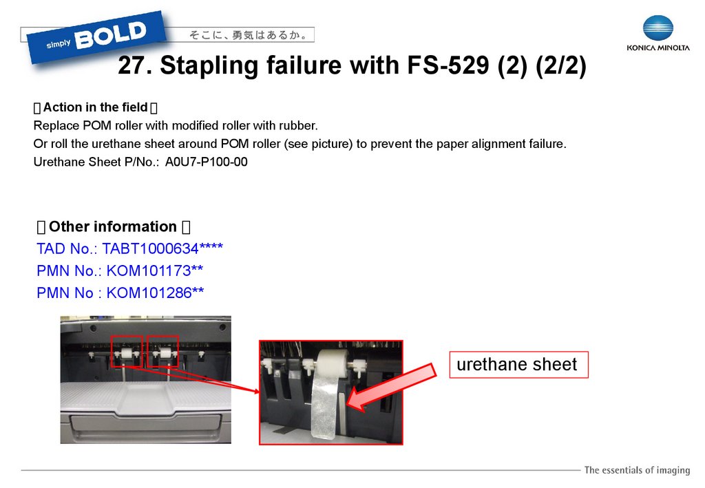
27. Stapling failure with FS-529 (2) (2/2)【 Action in the field 】
Replace POM roller with modified roller with rubber.
Or roll the urethane sheet around POM roller (see picture) to prevent the paper alignment failure.
Urethane Sheet P/No.: A0U7-P100-00
【 Other information 】
TAD No.: TABT1000634****
PMN No.: KOM101173**
PMN No : KOM101286**
urethane sheet
42.
28. Stapling failure with FS-529 (3) (1/2)【 Symptom 】
Output paper can not be stapled with the correct position.
【 Cause 】
Paper alignment guide is installed incorrectly.
【 Action in the field 】
Check the following and install correctly Paper alignment guide.
1)If the following measurement is longer than 11mm when Peper alignment guide is
in home position, Paper alignment guide is installed incorrectly.
11mm
Between touching
paper face and cover
11mm
Between touching paper
face and plate frame
11mm
11mm
43.
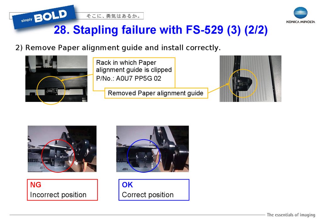
28. Stapling failure with FS-529 (3) (2/2)2) Remove Paper alignment guide and install correctly.
Rack in which Paper
alignment guide is clipped
P/No.: A0U7 PP5G 02
Removed Paper alignment guide
NG
Incorrect position
OK
Correct position
44.
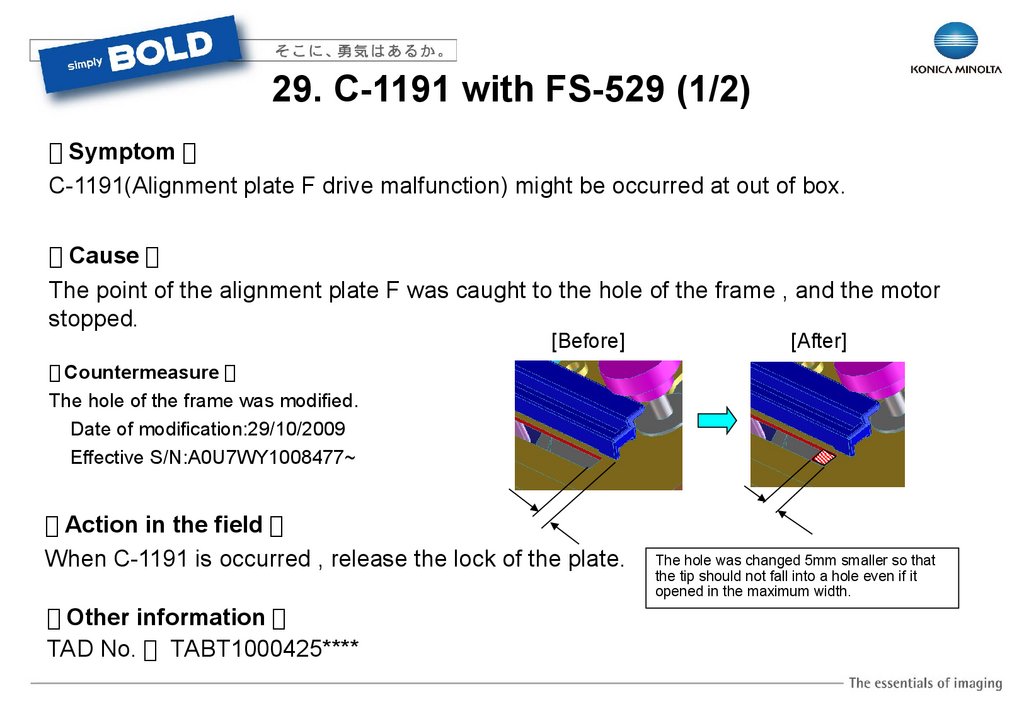
29. C-1191 with FS-529 (1/2)【 Symptom 】
C-1191(Alignment plate F drive malfunction) might be occurred at out of box.
【 Cause 】
The point of the alignment plate F was caught to the hole of the frame , and the motor
stopped.
[Before]
[After]
【 Countermeasure 】
The hole of the frame was modified.
Date of modification:29/10/2009
Effective S/N:A0U7WY1008477~
【 Action in the field 】
When C-1191 is occurred , release the lock of the plate.
【 Other information 】
TAD No. TABT1000425****
The hole was changed 5mm smaller so that
the tip should not fall into a hole even if it
opened in the maximum width.
45.
29. C-1191 with FS-529 (2/2)Move and contact the alignment plate to the front frame,
and vibrate it to front, back, left and right direction.
When it could not be released it even if it vibrates , desorbs the alignment plate few times
with holding the condition that the alignment plate and front frame are contacting.
(Picking the tip and pull it in the direction of the arrow.)
*disassembly the unit and release it when it could not be released.
46.
30.FS-529 Operating noise when moving exit tray【 Phenomenon 】
Some users point out that moving sound occurred when the UP/DOWN Tray is
moving down to home position after completed the job is uncomfortable.
【 Change 】
UP/DOWN Tray does not move down to home position after complete the job
and it starts to move to home position when starting the next job.
【 Reference 】
DLBT1002259EN00
Finisher Ver.A0U70Y0-0071-GC1-04
47.
31.Detection Failure of JS-505/FS-527 (1/2)Fig.1
【 Symptom 】
When the finisher option(JS-505/FS527) is installed to the main body,
JS-505/FS-527 cannot be detected.
Pin Drop out
Front side of FNS harness
Rear side of FN harness
【 Cause 】
The connector pin of FNS relay harness is dropped out. (Fig.1)
Factor of the pin drop out
The terminal of the connector pin of “JS-505 or FS-527” is bent. (Fig.2)
If the connecter of JS-505 or FS-527 is inserted the FNS relay harness, the connector pin is dropped out
by the interference which is caused by the bending of the terminal pin of JS-505/FS-527.
Factor of the bending of the connector pin
Manufacturing failure on the pressuring process of the connector pin.
48.
31.Detection Failure of JS-505/FS-527 (2/2)Fig.2
Zoom
Fig.3
Bending
The trace of the interference
with the connector pin.
【 Action in the field 】
Replace the FNS relay harness(P/No:A0EDN10D00)
【 Permanent Countermeasure 】
-Strengthen the quality management of the pressuring accuracy for the connector pin.
-Strengthen the inspection process on shipment.
49.
32. JAM Problem in FS-529 (J72-17) (1/2)【 Symptom 】
JAM(J72-17) occurs frequently in FS-529.
【 Cause 】
A) FW problem of FS-529 (incorrect setting of the Duty ratio of transportation motor.)
This problem occurs mostly on larger than B4 size.
B) JAM processing lever doesn't lock enough.
【 Countermeasure 】
A) Correction for incorrect setting of current value of transportation motor.
Countermeasure FW Ver.: A0U70Y0-0071-G01-04
B) Fill the gap between D cut part of shaft and lock lever by modifying the shape of D cut part.
Applied product S/No.: AOU7WY2015605 and onward
【 Other information 】
DL No.: DLBT1001299****
TAD No.: TABT1000813****
D cut part
50
50.
32. JAM Problem in FS-529 (J72-17) (2/2)【 Action in the field 】
Update the firmware to Ver. A0U70Y0-0071-G01-04 or later.
If JAM occurs frequently even after updating the firmware, check the following.
1) Attach a Mylar with the lower guide of paper entrance. (Perform this action on
2)
FS-529 which Model No. is only A0U7-WY1.)
Check the screw securing conveyance roller unit
and the positioning dowel.
Check the damage of the
positioning part. (Plastic part)
Check the loose of
the screw.
P/No.: A0U7 PPCR 00
3) Fill the gap between D cut part of the shaft and lock lever. (If 2) is no problem, perform this action.)
Fill the gap between the shaft and lock lever.
51
Dimension of Mylar
Length -> 10mm
Width -> 3mm
Thickness -> 0.1mm
Attach Mylar on the face of
D cut part by double-faced
tape.
51.
33. FS-529 C-1183【 Symptom 】
C-1183 (Elevate drive malfunction) is occurred.
【 Cause 】
Damage of worm gear [A0U7 PPBJ 01]
Worm gear
【 Countermeasure 】
Change the module of the appropriate gear.
Change other gear together and strength Tray up/down Assy.
Applied products: A0U7WY1014536 and onward
A0U7WY2006753 and onward
Tray up/down Assy
[A0U7 PPD0 00]
【 Action in the field 】
Replace Tray up/down Assy [A0U7 PPD0 00] or damaged
worm gear [A0U7 PPBJ 01]
【 Other information 】
TAD No.: TABT1000656****
PMN No.: KOM101127**
52.
34. JAM (72-87) occurs at the Center Staplein Fold mode on SD-509 (1/2)
【 Symptom 】
The JAM (72-87) occurs when the 1st sheet of 2nd set is stuck on the Center
Staple in Fold mode.
【 Condition 】
If all of the following conditions below 1), 2) and 3) are selected, this problem
should be occurred.
1) Center Staple & Fold mode
“0.8mm”
2) Paper size: 11X17 only
3) Half-Fold position in 11x17: “0.8mm”
Detail: Service mode
Finisher FS-FN adjustment
Fold position 11x17:0.8mm
Half-
53.
34. JAM (72-87) occurs at the Center Staplein Fold mode on SD-509 (2/2)
【 Combination 】
bizhub C452 Donau3)+FS-527+SD-509
bizhub C360/C280/C220 Amur)+FS-527+SD-509
【 Cause 】
Software bug in the firmware for SD-509.
When setting the Half-Fold position as 11x17: “0.8mm”, the movement control for the
Leading edge stopper was wrong.
【 Countermeasure 】
Released improved firmware (A10D-0Y0-0071-G00-03) for SD-509 in bizhub C452
and bizhub C360/C280/C220.
New firmware (Maintenance release Ver. 58 and onward) in available on the CSES.
【 Action in field 】
This problem occurs, when the Half-Fold position was set as 11x17: “0.8mm” ONLY
Set the figure to something except 0.8mm in the Half-Fold position 11x17.
【 Reference 】
(TABT0900181EN01)
54.
35. Wrong Booklet Tray Full Detection on SD-509 (1/2)【 Symptom 】
There is a possibility that the machine stops and displays the Tray Full warning
when only a few booklets have exited. This could happen when low stiffness
paper is used for the booklet and it is made up with only a few sheets of paper.
【 Cause 】
If the above mentioned booklet can not push up the arm on the booklet tray
(Lever/1), the booklet stops at the end of the arm and the trail edge of it can not
fully exit. This trail edge activates the tray full sensor and the machine stops and
displays the tray full warning.
【 Countermeasure/ Action in field 】
The Lever/1, mounting plate and other related parts were redesigned, and one
mounting plate was newly added.
Effective serial number (SD-509): A10DWY1009127 and onwards.
PMN (Parts Modification Notice): AUR100066, DEV100135, KOM100323,
OCE100125, OLT100090
* The parts changed in this redesign have to be changed as a set.
55.
35. Wrong Booklet Tray Full Detection on SD-509 (2/2)【 Symptom 】
【 Reference 】
(TABT1000156EN00)
【 Measure 】
56.
36.Paper alignment failure on FS-527 (1/2)
【 Symptom 】
A5 paper alignment trouble and staple failure on the FS-527 was found in the
production line.
This trouble has never been reported from the field.
【 Condition 】
Paper: A5LEF
Finishing mode: Staple mode
【 Cause 】
Because the Swing guide plate (A0HR715900) sometimes can not swing up quick
enough, the second sheet of paper could not enter underneath the guide correctly
before hitting the edge of it. This causes the misalignment of the sheets.
57.
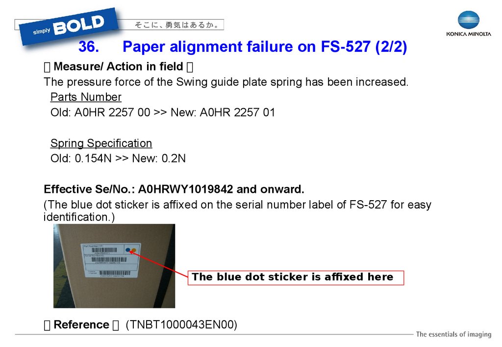
36.Paper alignment failure on FS-527 (2/2)
【 Measure/ Action in field 】
The pressure force of the Swing guide plate spring has been increased.
Parts Number
Old: A0HR 2257 00 >> New: A0HR 2257 01
Spring Specification
Old: 0.154N >> New: 0.2N
Effective Se/No.: A0HRWY1019842 and onward.
(The blue dot sticker is affixed on the serial number label of FS-527 for easy
identification.)
The blue dot sticker is affixed here
【 Reference 】 (TNBT1000043EN00)
58.
37. Operational noise from JS-504/505 (1/2)【 Symptom 】
There were several complaints from the Japanese market regarding the operational
sound of JS-504/505. To decrease operational sound, additional grease has been
applied to the gears on the JS-504/505 on the production line.
【 Countermeasure/ Action in field 】
1) Apply grease on the four gears.
Grease type: HP-500, P/No.1061792901
2) Add the cover on the board to avoid contamination by the grease.
59.
37. Operational noise from JS-504/505 (2/2)【 Countermeasure/ Action in field 】
1) Apply grease on the four
gears.
9314130061 motor gear
2) Add the cover on the board to avoid
contamination by the grease.
The upper surface
A0832102
A0831056
Side
A0832100
A0832101
Effective Se/No. will be notified by the Parts Modification Notice.
【 Reference 】 (TNBT1000027EN00)
【 Effective Se/No. 】 PMN KOM100846
60.
38. C-5501 (AC signal abnormality) (1/2)【 Symptom 】
"C5501" might sometimes be occurred in warming up, waiting or printing.
There is a possibility that this trouble code might occur if the machine is located near some
electrical noise such as a construction site, the private electric generator etc.
【 Cause 】
"C5501" checks the frequency of the power supply, and when the frequency becomes abnormal
because the noise gets on the power supply line, this trouble is detected.
(* Refer to the following waveform.)
If the noise occurs continuously on the
marked position, the abnormal frequency
will be detected.
61.
38. C-5501 (AC signal abnormality) (2/2)【 Countermeasure 】
The countermeasure firmware which improves the noise detection for the AC signal has been prepared.
<Notes:>
The control of the fusing heater doesn't work correctly when it cannot detect the frequency of the power
supply. Therefore, the trouble code of the fusing temperature error might appear.
Therefore, the function of C5501 was newly added because of a power supply environmental check.
However the machine works correctly even if it deletes C5501.
【 Action in the field 】
Update the firmware to the following version when the above symptom occurs.
DLBT1001593EN00 Ver. A0ED0Y0-0050-G10-04
【 Other information 】
TAD No. TABT1000021****
62.
39. C-B001【 Symptom 】
When the machine is warming up, C-B001 is detected after the FAX board is installed to the main body.
【 Cause 】
Check Sum error.
The check sum error occurs because the main body was turned OFF during ISW.
【 Countermeasure 】
N/A. This trouble is caused by the mistake of the operator.
【 Action in the field 】
Do not turn OFF the main body when the ISW is in the process of loading firmware.
If “C-B001” occurs, please proceed with the ISW again.
63.
40. C-B003 (1/2【 Symptom 】
When the machine is warming up, C-B003 is detected after FAX board is installed to the main body.
【 Countermeasure 】
There is the possibility that the connection between FAX board and the relay board
(MK-720) is loose.
【 Countermeasure 】
N/A
【 Action in the field 】
Confirm the connection condition between FAX board and the relay board (MK-720).
64.
40. C-B003 2/2OK
If the connecter of FAX board is not connected
completely (refer to the above picture), please
insert it to the correct position.
65.
41.C-2253/C-5102(DCPU failure)【 Symptom 】
C-2253(Color PC motor’s failure to turn), C5102(Transport motor’s failure to turn)
may occur by the failure of DCPU.
【 Cause 】
The output voltage of 24V does not output, because, the relay function of RL752
does not work due to the soldering failure of R752 on DCPU.
【 Action in the field 】
Please follow the service manual first, when C2253/C5102 symptom are happened in the
main body.
If the symptom cannot be resolved by the countermeasure which is mentioned on the
service manual and other action below, please replace DCPU.
[Others]
1. Replace Main Drive Assy.
2. Update the firmware.
66.
42. J14-01 when setting up PC-207【 Symptom 】
J14-01 occurs when setting up PC-207.
【 Cause 】
The poor connection occurs because of No.1 pin of [CN39] on PC-207 connects with
crushed.
【 Action in the field 】
Check Trouble Shooting on service manual and connection of [CN39], if J14-01 occurs when
setting up PC-207.
CN39
67
67.
43. Custom size is returned to Auto detection【 Symptom 】
The registered custom paper size of the bypass tray will be returned to Auto detection.
One of the cases for the occurrence condition is,
1. Set the paper of custom paper size to the bypass tray.
2. Register the custom size.
If the horizontal width for the registered paper size is near 114mm (between B6 and A5), it is easy for this symptom to
occur.
【 Cause 】
The sensitivity of resistance in the bypass tray is too tight. The resistance value is changed, when the guide is
to the position of the paper size switching, and then the change of paper size is detected and returned to Auto.
【 Countermeasure 】
The countermeasure firmware which has the correct level of the sensitivity for the detection of the paper size.
【 Action in the field 】
Update the firmware to the following version when the above symptom occurs.
DLBT1001593EN00 Ver. A0ED0Y0-0050-G10-04
put
68.
44. Detection failure of “Toner near empty” (1/2)【 Symptom 】
“Toner near empty” is detected, although toner still remains in the toner bottle.
【 Cause 】
The cause is the unevenly sensitivity of sensor .
This problem occurs by the sensor of too high sensitivity and wide detective range. The sensor detects the magnet at the position that must not react
normally. So “Toner near empty” is detected, although toner still remains in Sub Hopper Assy.
Magnet (fixed on the actuator)
Toner near empty sensor (magnetic type)
69
69.
44. Detection failure of “Toner near empty” (2/2)【 Countermeasure 】
“The lead switch selected in the production line is used.
Sub Hopper
Old P/No.: A0ED-R***-00 → New P/No.: A0ED-R***-01
【 Action in the field 】
Replace Sub hopper or the sensor with the new type.
Or Install Printer firmware Ver. A0ED0Y0-0050-G10-04 and onward.
Detection control of Toner near empty was fixed.
【 Other information 】
DLBT1001593EN00
PMN No.: KOM101193**
TAD No.: TABT1000136****
70
70.
45.“Front door open” is detected【 Symptom 】
There is a possibility that the “Front door open” is detected when only touching the front door softly.
【 Cause 】
【 Countermeasure 】
The lever of the front door falls into the following Shorten the distance shown on the picture by
space (shown with red arrow below) on the safety using the correct Torsion coil spring.
switch, then, “Front door open” is detected.
The space on the safety switch is created if the
Torsion coil spring is too short. It was found that
【 Action in the field 】
there is a variation in the size of parts.
Current P/No A0ED136700
New P/No
A0ED136701
Replace with the correct “Torsion coil spring”.
【 Other information 】
TAD No. TABT1000013****
PMN No. KOM100274
71.
46.Broken NVRAM connector【 Phenomenon 】
Panel freeze (KM logo or Hourglass mark)
Panel turns off / Trouble code CD390, CC164, CC170 display
Memory indicator does not reset after copy or print comes out.
【 Cause 】
NVRAM connector is broken
【 Countermeasure 】
Replace MFP board
Be careful when removing
and installing NVRAM on MFP board.
72.
47.Machine does not boot up(1/2)【 Symptom 】
The main body does not boot-up, if the UK-203(additional memory for i-Option) is
installed.
Operational Panel : Black
Start-key: Lighting with orange
Std. DIMM
*This problem is caused by only SanMax DIMM.
【 Cause 】
The data in Std. DIMM on MFP board which
controls the access timing from CPU was
programmed by the incorrect value.
The data mismatching between "Std DIMM(on
MFP board)" and "UK-203(additional DIMM) was
occurred when UK-203 was installed to the
machine.
Slots for DIMMs
on MFP board
Option DIMM
(UK-203)
Mis-programmed
DIMM(SanMax)
73.
47.Machine does not boot up(2/2)【 Action in the field 】
Please confirm the Std. DIMM, when installing the UK-203.
Please replace the Std. DIMM, if the same problem occurs.
【 Permanent Countermeasure 】
The internal data of DIMM was corrected. The following type of labels(Green/Orange)
are attached to the corrected DIMMs. (Fing.1)
- Green : attached in the new production process of the DIMM supplier.
- Orange : attached in the factory after re-writing the data to the returned DIMM.
Fig.1
【 Reference information 】
TAD No. TABT1000705EN00
74.
48.Trouble with Std. DIMM【 Symptom 】
There’re possibilities that the following symptom
are occurred by the failure of standard DIMM.
- Repeat the Hourglass mark
- Freeze the operational panel with the
Hourglass mark
- Black panel
- C-C170/172/186
Std. DIMM
【 Cause 】 (Example of the investigation result)
Functional error of the IC on the DIMM.
【 Countermeasure 】
Follow the service manual first when the above symptom are happened in the main body.
If the symptom cannot be resolved by the countermeasure which is mentioned on the service manual,
Replace the DIMM(Memory Module : V8653000025).
75.
49. Message on the panel (1/2)【 Symptom 】
The panel displays message ‘ Due to alert, the panel is illuminated ‘.
【 Cause 】
This message is displayed on MFP panel when receiving print order which has
mismatched information for the MFP in sleep (or Low power) mode.
(It may display by other reason. )
76
76.
49. Message on the panel (2/2)【 Example 】
When sending print job which is set punch and staple to MFP equipped with JS-505 and DF-617 in sleep mode.
(Because there are no punch and staple function with JS-505)
After MFP displays the message on the panel, print job is output without punch and staple processing.
not conforming setting
77
77.
50. Abnormal noise in the fuser pressure release motor (1/2)【 Symptom 】
When releasing of the pressure of fusing Unit, the abnormal
noise "Kee" might occur.
【 Cause 】
The abnormal noise "Kee" might occur because of the
rubbing of the tooth plane on the worm gear.
【 Countermeasure 】
When the abnormal noise occurs, execute the temporary solution
(1) or the temporary solution (2) .
<Temporary solution (1)>
Add two spacers (40383595) to the mounting plate to expand the
backlash (see slide 2/2).
<Temporary solution (2)>
Add weight (A0ED2313) to gear (A0ED2542). generation source
(The rotation of the gear is stabilized, and the vibration is decreased.)
<Permanent solution>
The part (A0ED2314) that integrates the gear with the weight is
newly established.
78.
50. Abnormal noise in the fuser pressure release motor (2/2)<Temporary solution (1)>
Add two spacers to the mounting plate
(4038-3595)
【 Action in the field 】
Same as above [Countermeasure].
【 Other information 】
TAD No. TABT1000022****
<Temporary solution (2)>
Add weight (A0ED2313)
to gear (A0ED2542).
<Permanent solution>
The part (A0ED2314) that integrates
the gear with the weight
79.
51. Noise from neutralization brush (1/2)【 Symptom 】
The abnormal sound created by the scratching of the neutralization brush on the exiting
paper.
【 Cause 】
The amount of adhesive bond for neutralization brush was too much and the brush was
fixed (glued together) by this bond.
Neutralization brush
80.
51. Noise from neutralization brush (2/2)Current
New
【 Countermeasure 】
Sound could be reduced by reducing the amount of adhesive bond and therefore the
quality of the brush becomes softer.
【 Action in the field 】
Replace the neutralization brush with the new type of one.
Current P/N A02E890700
New P/N A0ED890700
81.
52. Noise from DCPU【 Symptom 】
When waiting for printing (or at idle), a noise comes from the DCPU.
This noise is created when controlling the fuser temperature, and comes from the coil section of
the noise filter.
【 Cause 】
From the C353 series, the function which controls the fusing heater when “heat ON/OFF”, “wake
up/down” smoothly was added.
When this function works, the sound occurs by resonating the coils.
【 Countermeasure 】
Prepare the countermeasure firmware which does NOT smoothly work the control for the fusing
heater to improve the sound.
For the future plan, this controlling of the fusing heater can be switched by a Soft Switch.
【 Action in the field 】
DLBT1001593EN00 Ver. A0ED0Y0-0050-G10-04
Apply the countermeasure firmware when the above symptom will be pointed out by the end user.
However, there is the possibility that the flicking of the customers office lights may occur. This will depend on the
customer’s environment.
82.
53. Sound occurs when feeding Thick paper【 Symptom 】
Sound occurs when feeding the Thick paper. It is louder compared with the normal paper.
【 Cause 】
This sound occurs because the feeding paper vibrates the motor.
To realize the optimization of the fusing ability, the paper transportation speed is
controlled by changing the motor pulse when Thick paper is fed.
【 Countermeasure/Action in the field 】
There is not any modification plan at this moment since this is same level as the C353
series.
83.
54. Relay on DCPU chattering when turning ON main SW【 Symptom 】
After installation of the USB expansion module EK-605, and when you turn ON the machine for the first time for doing
adjustments, the MFP fails to start up.
A relay on the DCPU is making two "clicking" sounds (ON/OFF ?) just after turning ON with main switch. Between both "clicks"
the time is only around one second.
【 Cause 】
The socket pins of PJ05 (especially Pin1 5V) are touching the metal frame and so the 5V line is shorted to ground.
The reason was because an angle of the metal frame was bent towards the down side.
【 Countermeasure 】
A mylar sheet was added on the metal frame
under the PWB area.
This has been applied on the production line
since Sep/2009.
【 Action in the field 】
When the problem occurs, correct the angle of metal frame.
【 Other information 】
TAD No. TABT0900153****
84.
55. Noise occurs when feeding paper in ADU【 Phenomenon 】
Noise occurs when printing 2-sided A3 paper in ADU.
【 Cause 】
The sheet of paper with moisture uptake produced large loop at the guide and this loop
generate the resistance and noise occurs.
【 Countermeasure 】
Adjust Resist. Value to more + side or – side.
85.
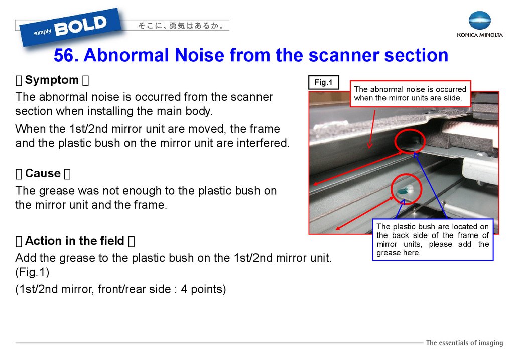
56. Abnormal Noise from the scanner section【 Symptom 】
The abnormal noise is occurred from the scanner
section when installing the main body.
When the 1st/2nd mirror unit are moved, the frame
and the plastic bush on the mirror unit are interfered.
Fig.1
The abnormal noise is occurred
when the mirror units are slide.
【 Cause 】
The grease was not enough to the plastic bush on
the mirror unit and the frame.
【 Action in the field 】
Add the grease to the plastic bush on the 1st/2nd mirror unit.
(Fig.1)
(1st/2nd mirror, front/rear side : 4 points)
The plastic bush are located on
the back side of the frame of
mirror units, please add the
grease here.
86.
57. Tray comes out【 Symptom 】
There is a possibility that the feed tray could come out.
【 Cause 】
1. The power of the lock lever is poor.
2. The correct amount of lubricanting agent (MH Surf) was not
applied to the lock lever.
【 Countermeasure 】
The power of the spring for the lock lever was improved.
【 Action in the field 】
Replace the spring when this symptom occurs.
Current P/N A0ED635800
New P/N A0ED635801
【 Other information 】
TAD No. TABT0900211****
Lubricant agent
(MH Surf)
87.
58. Tearing off Neutralizing brush from Cover Output (1/2)【 Symptom 】
Neutralizing brush (A02E8907**) fixed on the Output Cover (A0ED8901**) may tear OFF as per the
below picture. This will affect the alignment of feeding paper to the Output tray.
【 Cause 】
If there is not enough adhesive power in the neutralization brush, this brush may be peel off.
The conductive tape of the neutralization brush is rubbed by the earth spring, when the paper exit
cover is opened and closed.
Paper Exit Cover P/No. A0ED8901**
Neutralization brush P/No. A02E8907**
【 Countermeasure 】
Added the conductive tape (P/No. 40363075**) to the neutralization brush to improve the strength.
【 Action in the field 】
Put the additional conductive tape on the edge of neutralization brush.
For details, refer to slide 2/3.
【 Other information 】
TAD No. TABT0900184****
PMN No. KOM091422**
88.
58. Tearing off Neutralizing brush from Cover Output (2/2)A02E8907 Neutralizing brush
40363075 Conductive Tape
A0ED8901 Cover (Output
Gap from standard position
0 1mm
Standard position
Air should not be inside except around rib
Gap
0 1mm
89.
59. Cable Cover cannot be closed completely (1/2)【 Symptom 】
There are two possibilities where you cannot close the cable cover completely….
1. In the case where the cabinet is NOT used, the cables cannot be boxed up around the cable exit position.
2. In case where the cabinet is used, cables are run on the cover.
<Without Cabinet>
【 Cause 】
1. Cables cannot be fixed completely.
2. There is no function to fix the cover.
<With Cabinet>
90.
59. Cable Cover cannot be closed completely (2/2)【 Countermeasure 】
The design of cover was changed (as per the following picture) to the type where two cord clamps can be set.
Also 2 pcs of the cord clamp are bundled in the brand new machine as standard accessories.
Recommendation
【 Countermeasure 】
Put the LAN cable, CSRC cable etc as recommended (in the right
picture).
In either case, where the cabinet will be used or not used, install
the clamp and fix the cables as necessary.
91.
60. 2nd paper feeding guide is broken【 Symptom 】
2nd paper feeding guide is broken by user when clearing paper JAM.
【 Cause 】
If 2nd paper feeding guide is pull strongly, the guide bend and overlap the stopper and
catch on the stopper. The guide is broken when right door is close unawares.
【 Action in the field 】
Advise the User when clearing paper JAM.
If paper feeding guide is broken, replace it.
The stopper of Main Unit
The stopper of paper
feeding guide
The guide overlap the stopper
92
92.
61. Actuator detecting paper JAM at exit section is broken【 Symptom 】
Actuator detecting paper JAM at exit section is broken by user
when clearing paper JAM.
【 Countermeasure 】
Strength Actuator detecting paper JAM at exit section.
Current P/No.: A0ED 8207 01 -> New P/No.: A0ED 8207 02
【 Action in the field 】
If actuator is broken, replace to improved one.
【 Other information 】
TAD No.: TABT1000758****
PMN No.: KOM110018**
Actuator detecting paper
JAM at exit section
Broken
actuator
93
93.
62.Left side cover can’t be replaced【 Contents 】
This left side cover can’t be replaced since this cover
is a part of main flame.
Handle with care when transporting machine.
Some protection for preventing scratch would
be highly recommended for the transportation.