


 Электроника
Похожие презентации:


Training Book. Samsung Home Theater
1.
Samsung Home Theater-Home Theater System –
HT-TXQ120
Project : Tarzan / Project Grade : 3
Samsung Electronics Co. LTD
Digital AV Division
1
2.
List Of Contests1. General Feature of the HT-TXQ120
2. Description of the SET
3. How to Disassemble Main Set
4. How to Disassemble Sub Woofer
5. Special Feature
6. PCB Block Description & Trouble Shooting
7. MECHA DECK Disassemble
8. Micom / MPEG update & Initialization method
9. HT-TXQ120 BLOCK DIAGRAM / Schematic Diagram
10. Accessories
2
3.
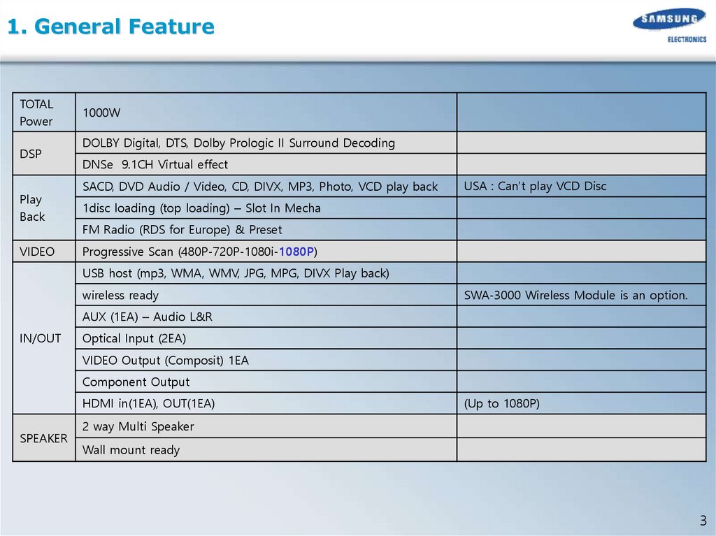
1. General FeatureTOTAL
Power
DSP
Play
Back
VIDEO
1000W
DOLBY Digital, DTS, Dolby Prologic II Surround Decoding
DNSe 9.1CH Virtual effect
SACD, DVD Audio / Video, CD, DIVX, MP3, Photo, VCD play back
USA : Can’t play VCD Disc
1disc loading (top loading) – Slot In Mecha
FM Radio (RDS for Europe) & Preset
Progressive Scan (480P-720P-1080i-1080P)
USB host (mp3, WMA, WMV, JPG, MPG, DIVX Play back)
wireless ready
SWA-3000 Wireless Module is an option.
AUX (1EA) – Audio L&R
IN/OUT
Optical Input (2EA)
VIDEO Output (Composit) 1EA
Component Output
HDMI in(1EA), OUT(1EA)
SPEAKER
(Up to 1080P)
2 way Multi Speaker
Wall mount ready
3
4.
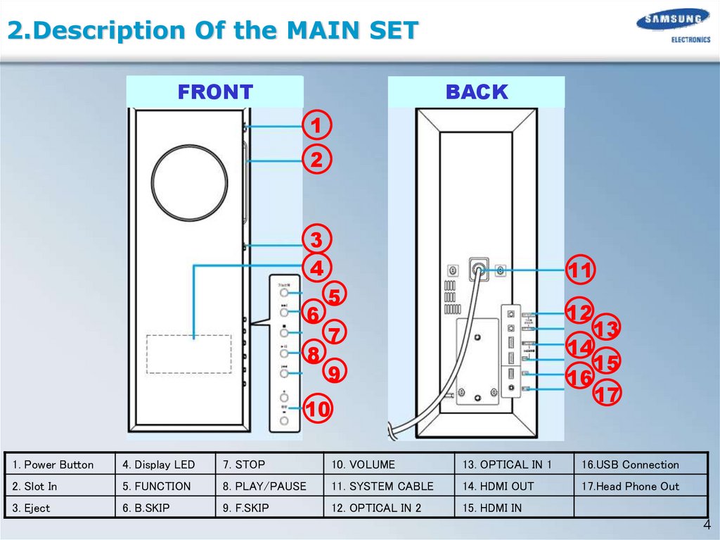
2.Description Of the MAIN SETFRONT
BACK
1
2
3
4
6
8
11
5
12
13
14
15
16
17
7
9
10
1. Power Button
4. Display LED
7. STOP
10. VOLUME
13. OPTICAL IN 1
16.USB Connection
2. Slot In
5. FUNCTION
8. PLAY/PAUSE
11. SYSTEM CABLE
14. HDMI OUT
17.Head Phone Out
3. Eject
6. B.SKIP
9. F.SKIP
12. OPTICAL IN 2
15. HDMI IN
4
5.
2.Description Of the MAIN SETFunction Description
1. Power Button
Power On / Off
2. Disc Slot
Disc Slot in / out
3. Eject Button
Disc Eject Button
4. LED DISPLAY
LED DISPLAY. It display SET mode, DVD play time, etc..
5. Function button
Mode select button. (DVD/USB/FM/HDMI/AUX/D.IN)
6. SKIP button (Back)
Back Skip Button (Disc Play)
7. STOP button
DISC Stop Button
8. Play/Pause button
Disc Play and Pause Button
9. SKIP button (FF)
Forward Skip Button (Disc Play)
10. Volume
Volume control button (0~50)
11. System Cable
Main Set Sub Woofer Set Power/Video/Audio data communication line
12. Optical input 2
Optical Digital audio in 2
13. Optical input 1
Optical Digital audio in 1
14. HDMI OUTPUT
HDMI OUTPUT. Connect HDMI Connector of TV
15. HDMI INPUT
HDMI INPUT. Connect with BD player, Game Controller… which has HDMI Connection
16. USB
For USB Host play Connect your USB player.
17. Head phone
Head phone Out.
5
6.
2.Description Of the Sub WooferFRONT
BACK
3
4
1
5
2
11 10
9
6
7
8
1. STANDBY LED
4.SPAKER OUT
7.COMPONENT OUT
10. Wireless TX Card Slot
2. POWER ON LED
5.FAN
8.COMPOSIT OUT
11. SYSTEM CABLE
3. ASC MIC IN
6.TUNER ANT
9.AUX IN
6
7.
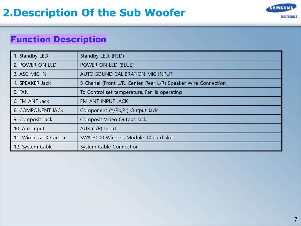
2.Description Of the Sub WooferFunction Description
1. Standby LED
Standby LED. (RED)
2. POWER ON LED
POWER ON LED (BLUE)
3. ASC MIC IN
AUTO SOUND CALIBRATION MIC INPUT
4. SPEAKER Jack
5 Chanel (Front L/R, Center, Rear L/R) Speaker Wire Connection
5. FAN
To Control set temperature, Fan is operating
6. FM ANT Jack
FM ANT INPUT JACK
8. COMPONENT JACK
Component (Y/Pb,Pr) Output Jack
9. Composit Jack
Composit Video Output Jack
10. Aux Input
AUX (L/R) Input
11. Wireless TX Card In
SWA-3000 Wireless Module TX card slot
12. System Cable
System Cable Connection
7
8.
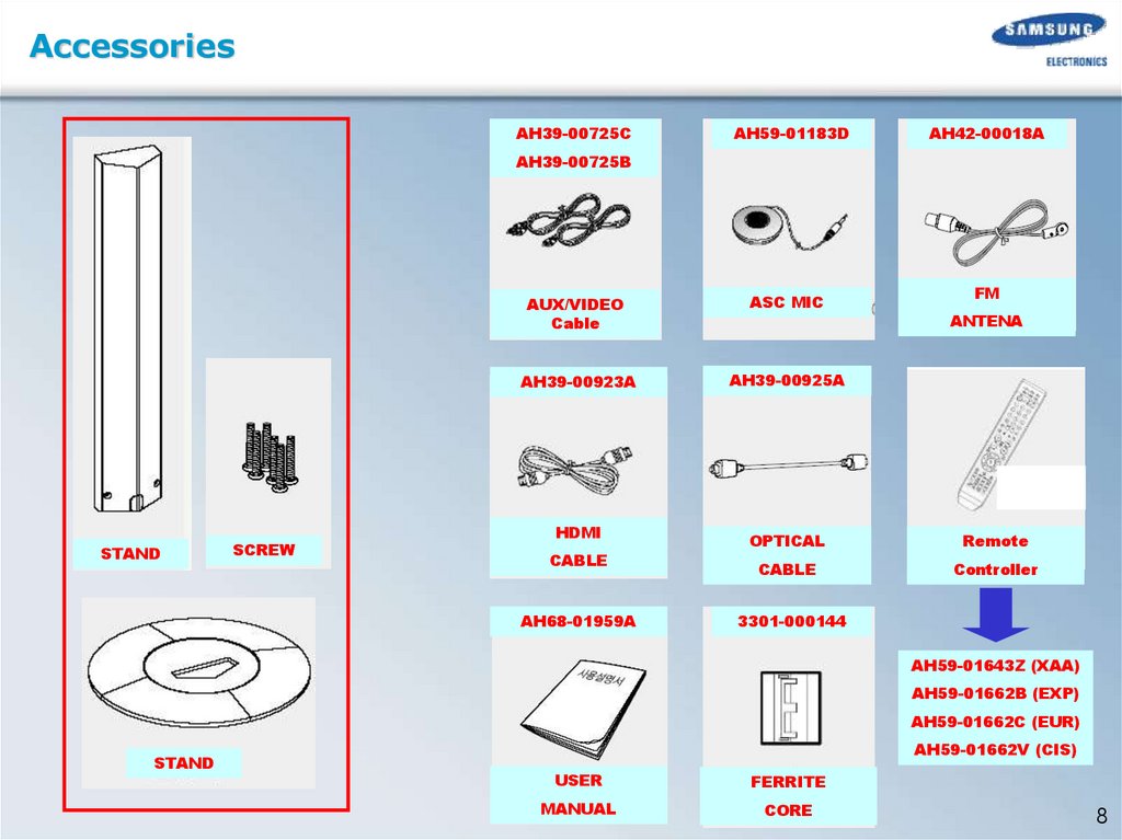
AccessoriesAH39-00725C
AH59-01183D
AH42-00018A
AH39-00725B
STAND
SCREW
AUX/VIDEO
Cable
ASC MIC
AH39-00923A
AH39-00925A
HDMI
CABLE
AH68-01959A
FM
ANTENA
OPTICAL
Remote
CABLE
Controller
3301-000144
AH59-01643Z (XAA)
AH59-01662B (EXP)
AH59-01662C (EUR)
STAND
AH59-01662V (CIS)
USER
FERRITE
MANUAL
CORE
8
9.
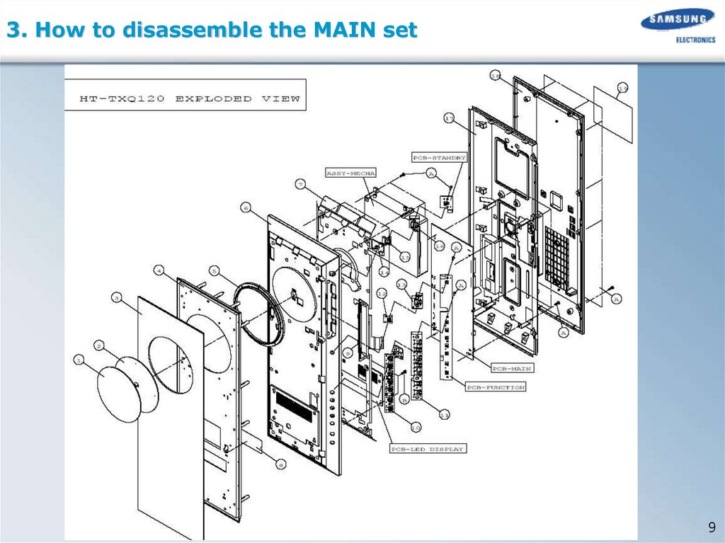
3. How to disassemble the MAIN set9
10.
3.How to disassemble the MAIN set1. Disassemble the Back Cover & SYSTEM CABLE
(※CAUTION! The System Cable)
1. Unfasten 12 screws on side of Back Cover
2.Lift the Back Cover.
(※Check The position of the Ferrite Core )
3.Unfasten 4 screws and lift up the cover.
4.Unfasten the System Cable Connector
(UDIN1,UDIN2).
10
11.
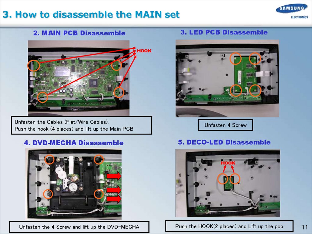
3. How to disassemble the MAIN set3. LED PCB Disassemble
2. MAIN PCB Disassemble
HOOK
Unfasten the Cables (Flat/Wire Cables),
Push the hook (4 places) and lift up the Main PCB
Unfasten 4 Screw
4. DVD-MECHA Disassemble
5. DECO-LED Disassemble
HOOK
Unfasten the 4 Screw and lift up the DVD-MECHA
Push the HOOK(2 places) and Lift up the pcb
11
12.
4. How to disassemble the Sub Woofer12
13.
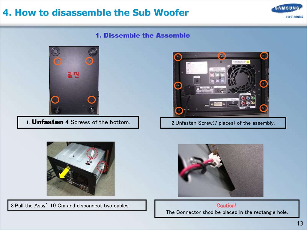
4. How to disassemble the Sub Woofer1. Dissemble the Assemble
밑면
1. Unfasten 4 Screws of the bottom.
3.Pull the Assy’ 10 Cm and disconnect two cables
2.Unfasten Screw(7 places) of the assembly.
Caution!
The Connector shod be placed in the rectangle hole.
13
14.
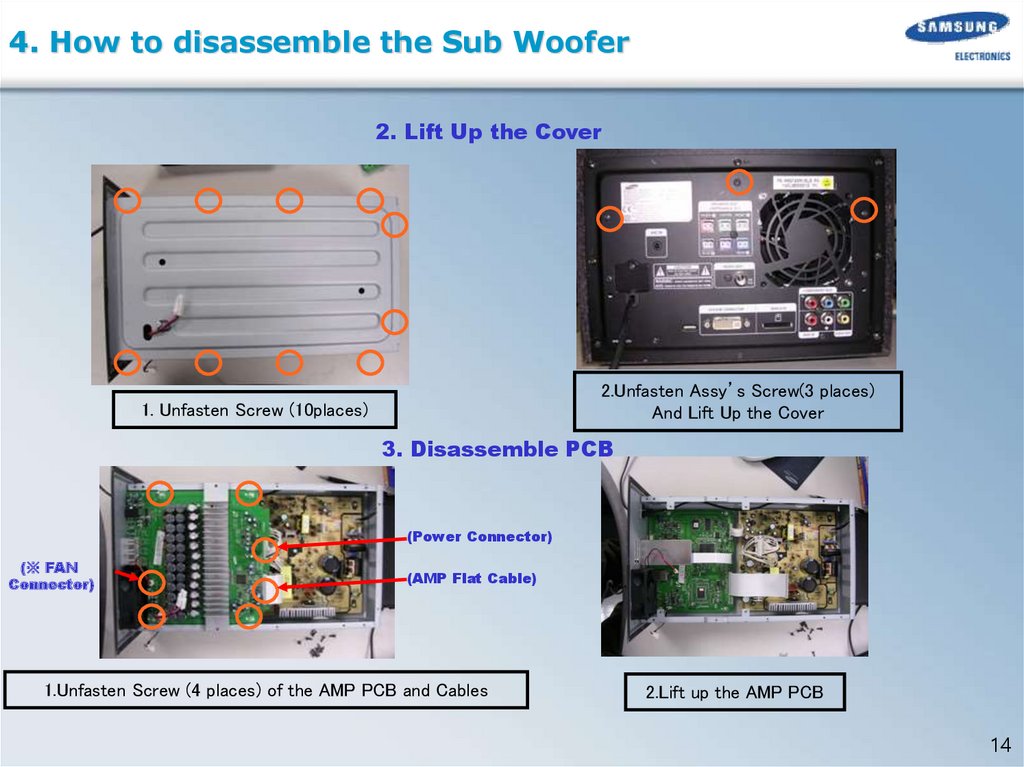
4. How to disassemble the Sub Woofer2. Lift Up the Cover
2.Unfasten Assy’s Screw(3 places)
And Lift Up the Cover
1. Unfasten Screw (10places)
3. Disassemble PCB
(Power Connector)
(※ FAN
Connector)
(AMP Flat Cable)
1.Unfasten Screw (4 places) of the AMP PCB and Cables
2.Lift up the AMP PCB
14
15.
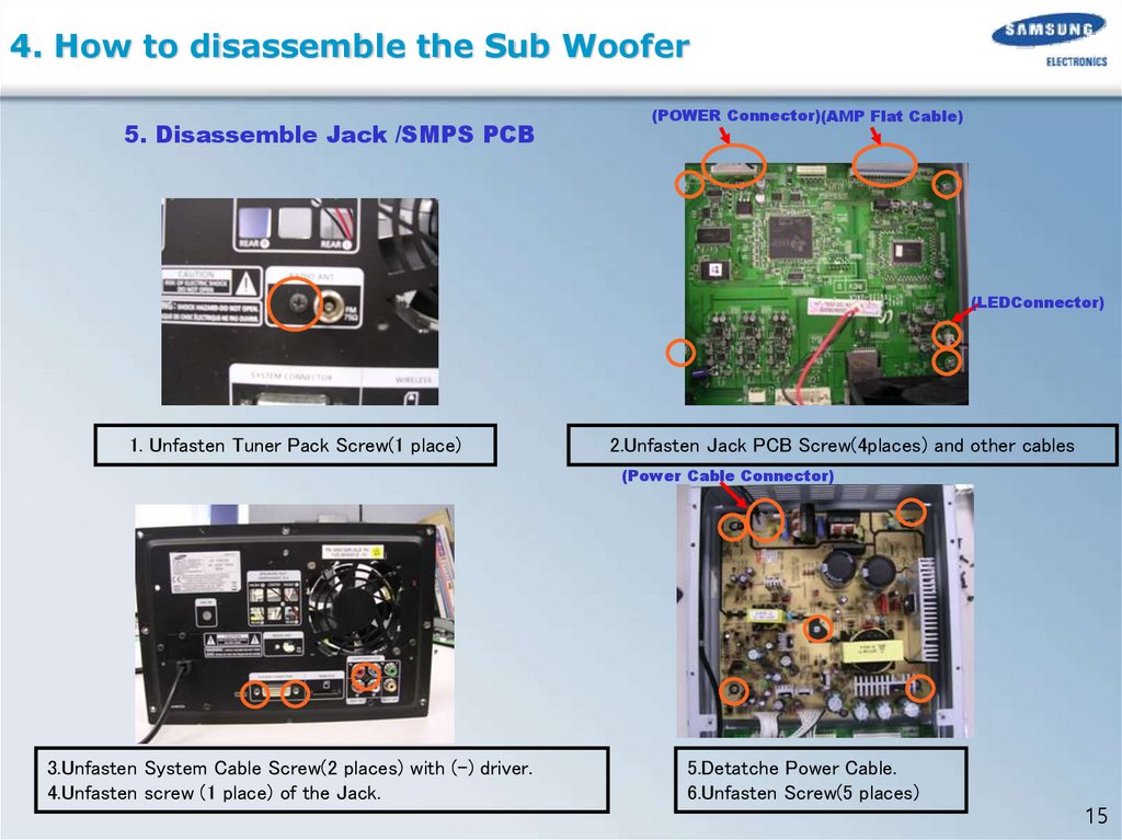
4. How to disassemble the Sub Woofer5. Disassemble Jack /SMPS PCB
(POWER Connector)(AMP Flat Cable)
(LEDConnector)
1. Unfasten Tuner Pack Screw(1 place)
2.Unfasten Jack PCB Screw(4places) and other cables
(Power Cable Connector)
3.Unfasten System Cable Screw(2 places) with (-) driver.
4.Unfasten screw (1 place) of the Jack.
5.Detatche Power Cable.
6.Unfasten Screw(5 places)
15
16.
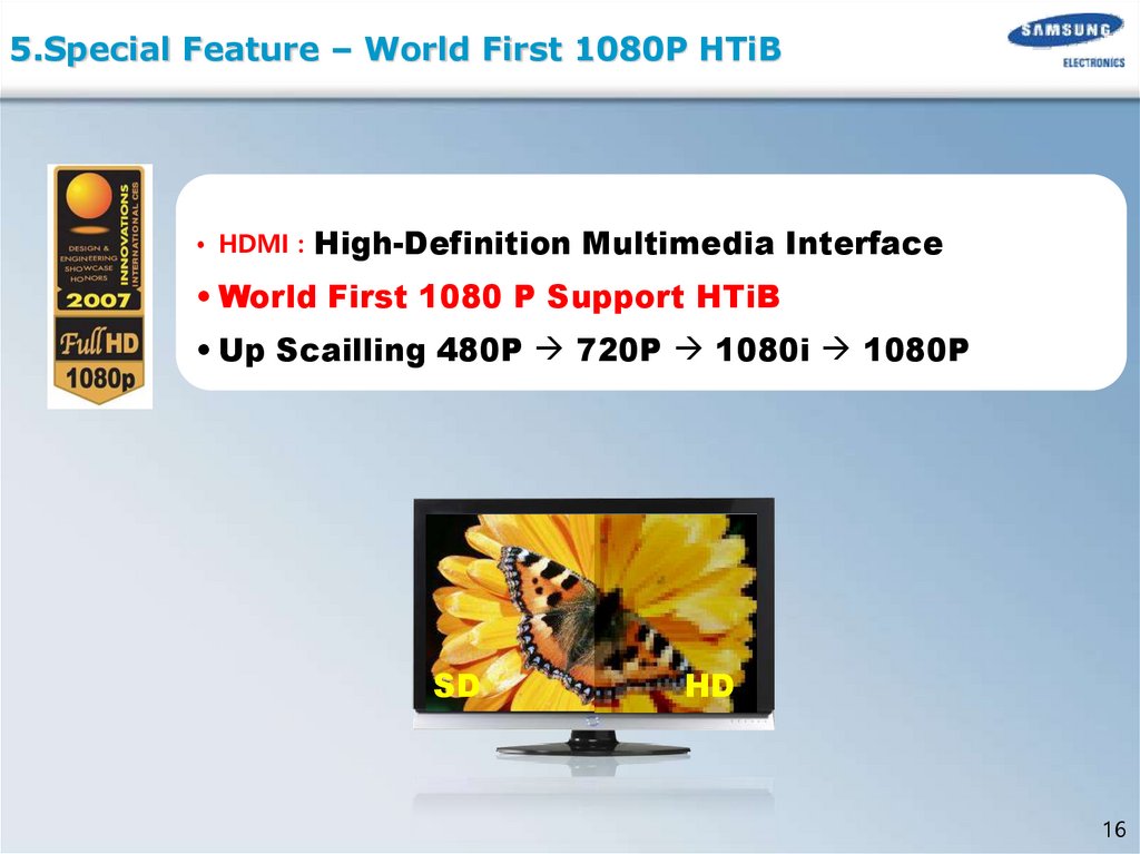
5.Special Feature – World First 1080P HTiB• HDMI :
High-Definition Multimedia Interface
• World First 1080 P Support HTiB
• Up Scailling 480P 720P 1080i 1080P
SD
HD
16
17.
5.Special Feature – HDMI IN & OUTHDMI (High Definition Multimedia Interface)
- Pure Digital for Perfect Vision
HDMI OUTPUT - High Definition DIGITAL Picture
Digital-toAnalog Converter
Digital Signal
Processing
HDMI INPUT – FOR DIGITAL CONNECTION with another Product
Bluray Disc Player
DVD Player
Input
Game Console
Output
17
18.
5.Special Feature – WIRELESS READY Block Diagram5. BLOCK DIAGRAM
18
19.
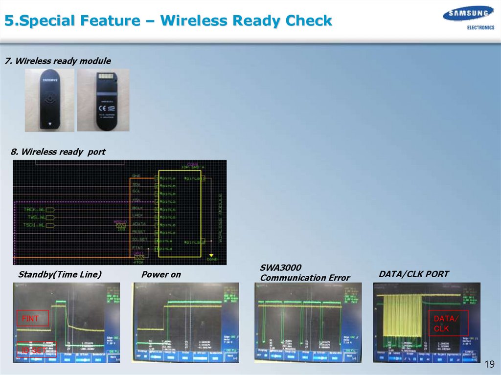
5.Special Feature – Wireless Ready Check7. Wireless ready module
8. Wireless ready port
Standby(Time Line)
FINT
Power on
SWA3000
Communication Error
DATA/CLK PORT
DATA/
CLK
ID SET
19
20.
6.MAIN PCB Block(1)MAIN TOP
OPTICAL/HDMI / USB / ASC JACK
MPEG
USB
PART
HDMI
SAA7128
POWER
Micom
(2)MAIN BOTTOM
MICOM
OPTION
WM 8746
20
21.
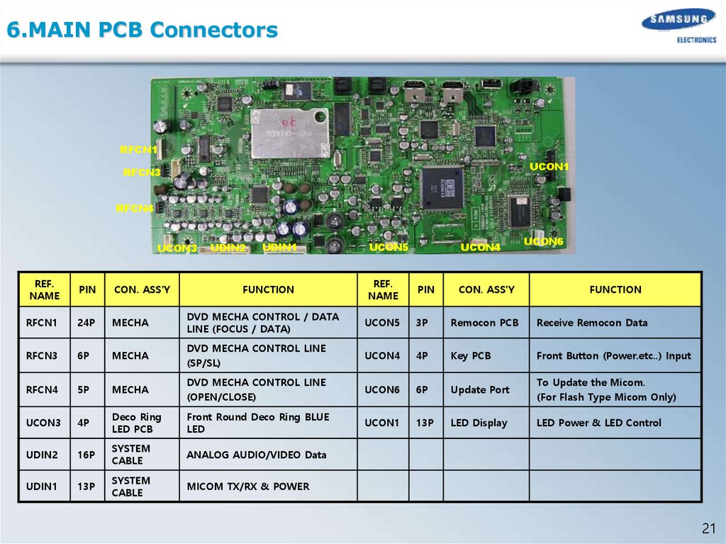
6.MAIN PCB ConnectorsRFCN1
UCON1
RFCN3
RFCN4
UCON3
UDIN2
UDIN1
UCON5
UCON6
REF.
NAME
PIN
CON. ASS'Y
RFCN1
24P
MECHA
DVD MECHA CONTROL / DATA
LINE (FOCUS / DATA)
UCON5
3P
Remocon PCB
Receive Remocon Data
RFCN3
6P
MECHA
DVD MECHA CONTROL LINE
(SP/SL)
UCON4
4P
Key PCB
Front Button (Power.etc..) Input
RFCN4
5P
MECHA
DVD MECHA CONTROL LINE
(OPEN/CLOSE)
UCON6
6P
Update Port
To Update the Micom.
(For Flash Type Micom Only)
UCON3
4P
Deco Ring
LED PCB
Front Round Deco Ring BLUE
LED
UCON1
13P
LED Display
LED Power & LED Control
UDIN2
16P
SYSTEM
CABLE
ANALOG AUDIO/VIDEO Data
UDIN1
13P
SYSTEM
CABLE
MICOM TX/RX & POWER
FUNCTION
REF.
NAME
UCON4
PIN
CON. ASS'Y
FUNCTION
21
22.
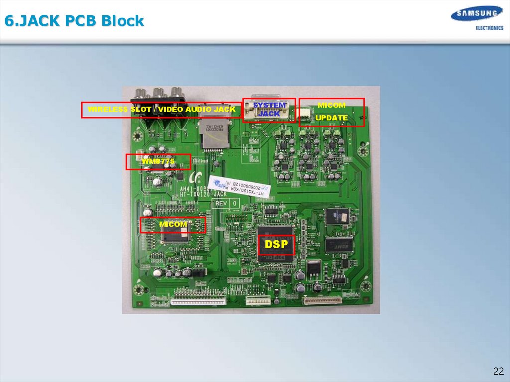
6.JACK PCB BlockWIRELESS SLOT / VIDEO AUDIO JACK
SYSTEM
JACK
MICOM
UPDATE
WM8775
MICOM
DSP
22
23.
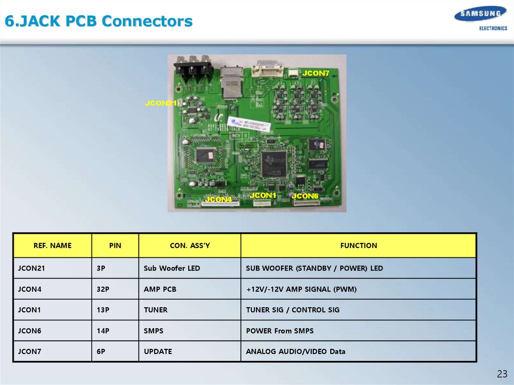
6.JACK PCB ConnectorsJCON7
JCON21
JCON4
REF. NAME
PIN
JCON1
JCON6
CON. ASS'Y
FUNCTION
JCON21
3P
Sub Woofer LED
SUB WOOFER (STANDBY / POWER) LED
JCON4
32P
AMP PCB
+12V/-12V AMP SIGNAL (PWM)
JCON1
13P
TUNER
TUNER SIG / CONTROL SIG
JCON6
14P
SMPS
POWER From SMPS
JCON7
6P
UPDATE
ANALOG AUDIO/VIDEO Data
23
24.
6.Block Diagram (Amp Block)PS9829B
24
25.
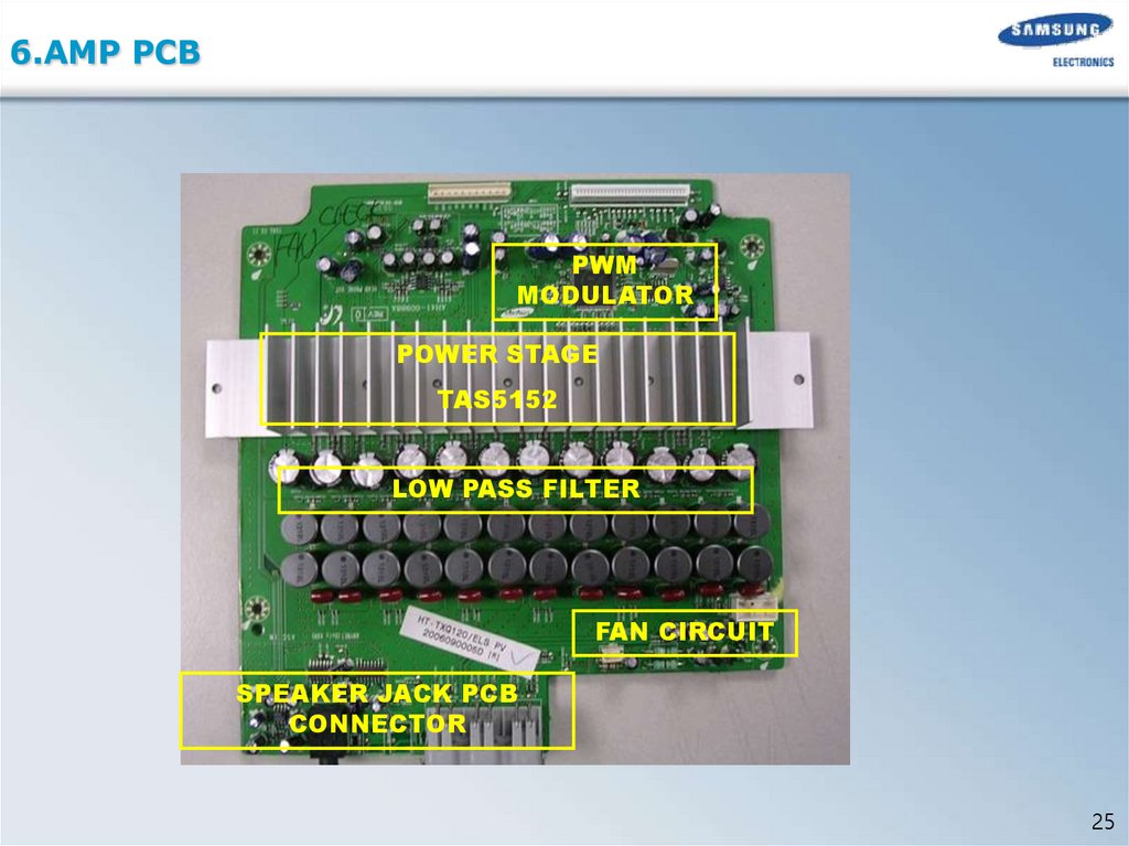
6.AMP PCBPWM
MODULATOR
POWER STAGE
TAS5152
LOW PASS FILTER
FAN CIRCUIT
SPEAKER JACK PCB
CONNECTOR
25
26.
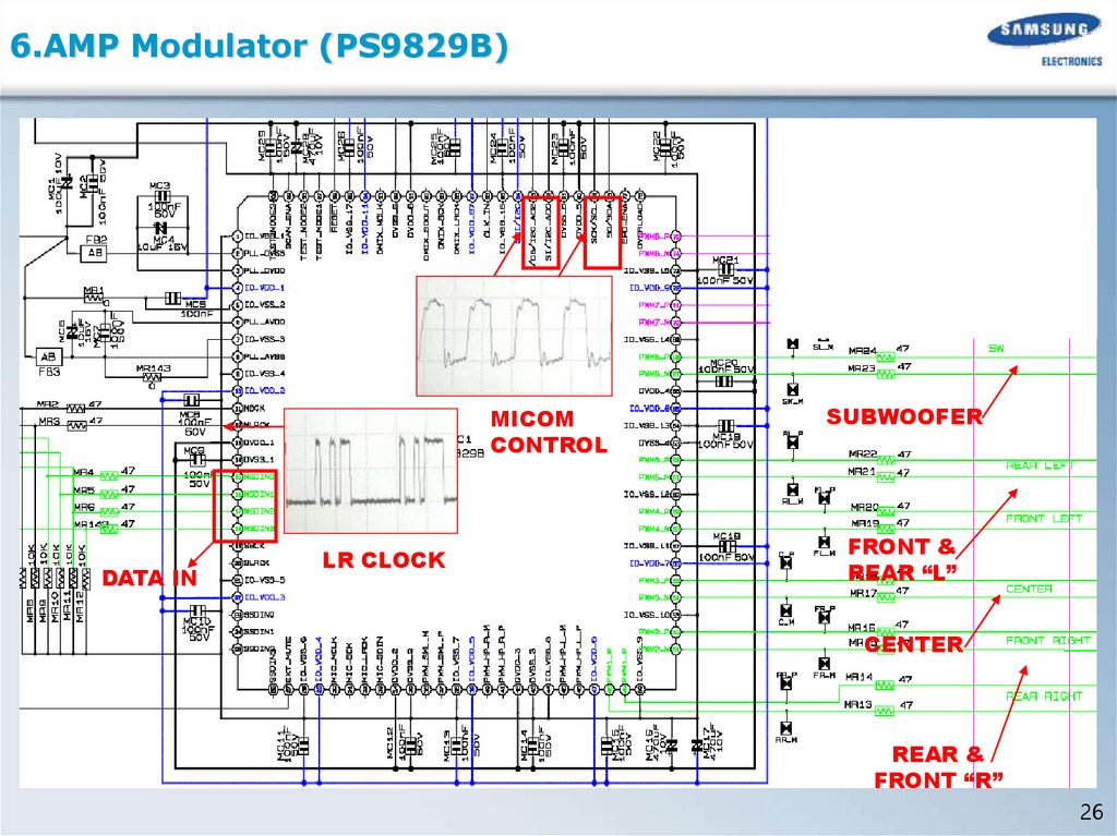
6.AMP Modulator (PS9829B)MICOM
CONTROL
DATA IN
LR CLOCK
SUBWOOFER
FRONT &
REAR “L”
CENTER
REAR &
FRONT “R”
26
27.
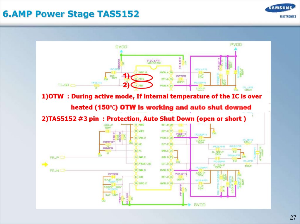
6.AMP Power Stage TAS51521)
2)
1)OTW : During active mode, If internal temperature of the IC is over
heated (150℃) OTW is working and auto shut downed
2)TAS5152 #3 pin : Protection, Auto Shut Down (open or short )
27
28.
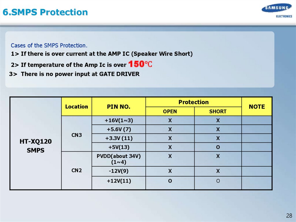
6.SMPS ProtectionCases of the SMPS Protection.
1> If there is over current at the AMP IC (Speaker Wire Short)
2> If temperature of the Amp Ic is over
150℃
3> There is no power input at GATE DRIVER
Location
HT-XQ120
SMPS
CN3
CN2
PIN NO.
Protection
OPEN
SHORT
+16V(1~3)
X
X
+5.6V (7)
X
X
+3.3V (11)
X
X
+5V(13)
X
O
PVDD(about 34V)
(1~4)
X
X
-12V(9)
X
X
+12V(11)
O
O
NOTE
28
29.
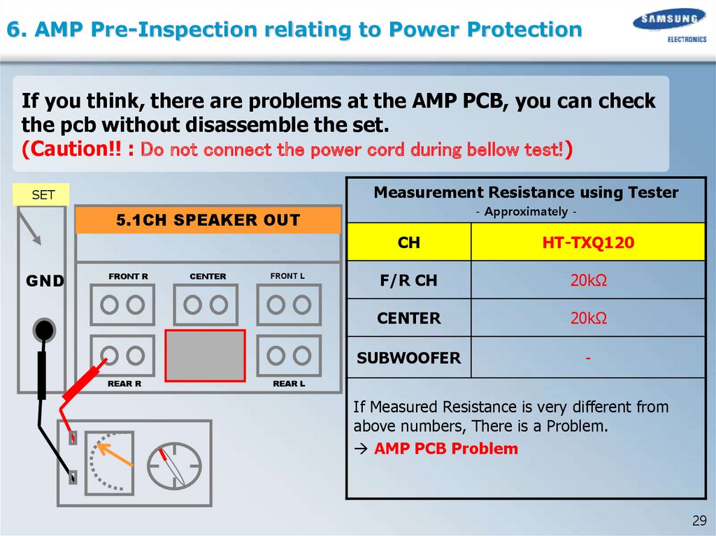
6. AMP Pre-Inspection relating to Power ProtectionIf you think, there are problems at the AMP PCB, you can check
the pcb without disassemble the set.
(Caution!! : Do not connect the power cord during bellow test!)
Measurement Resistance using Tester
SET
- Approximately -
5.1CH SPEAKER OUT
GND
FRONT R
REAR R
CENTER
FRONT L
CH
HT-TXQ120
F/R CH
20kΩ
CENTER
20kΩ
SUBWOOFER
-
REAR L
If Measured Resistance is very different from
above numbers, There is a Problem.
AMP PCB Problem
29
30.
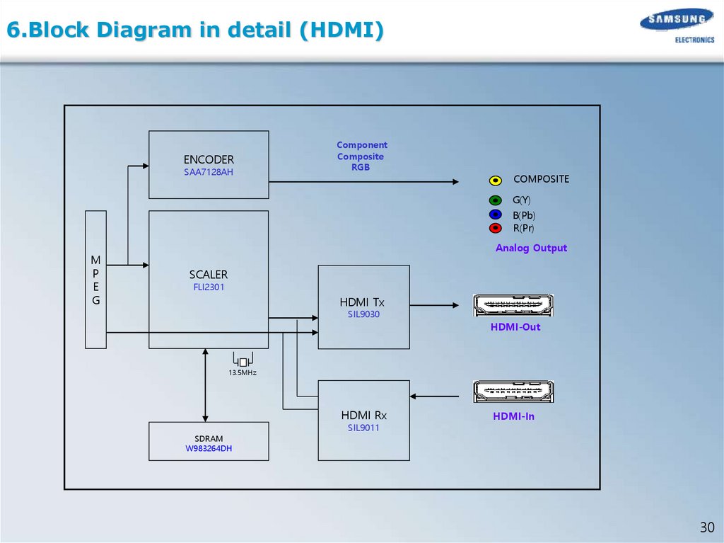
6.Block Diagram in detail (HDMI)ENCODER
SAA7128AH
Component
Composite
RGB
COMPOSITE
G(Y)
B(Pb)
R(Pr)
M
P
E
G
Analog Output
SCALER
FLI2301
HDMI Tx
SIL9030
HDMI-Out
13.5MHz
HDMI Rx
SDRAM
W983264DH
SIL9011
HDMI-In
30
31.
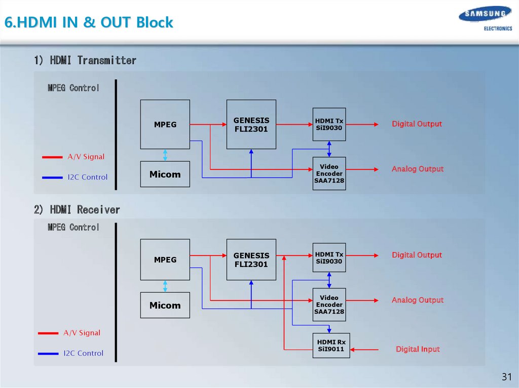
6.HDMI IN & OUT Block1) HDMI Transmitter
MPEG Control
MPEG
GENESIS
FLI2301
HDMI Tx
SiI9030
Digital Output
Video
Encoder
SAA7128
Analog Output
HDMI Tx
SiI9030
Digital Output
Video
Encoder
SAA7128
Analog Output
A/V Signal
I2C Control
Micom
2) HDMI Receiver
MPEG Control
MPEG
Micom
GENESIS
FLI2301
A/V Signal
I2C Control
HDMI Rx
SiI9011
Digital Input
31
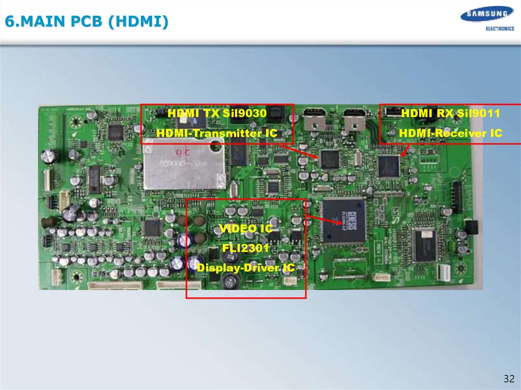
32.
6.MAIN PCB (HDMI)HDMI TX Sil9030
HDMI RX Sil9011
HDMI-Transmitter IC
HDMI-Receiver IC
VIDEO IC
FLI2301
Display-Driver IC
32
33.
6.Checking out AMP PCB1.PCB ASS’Y
2.HEAT SINK
3.PCB Short
Unfasten 7 Screws
Separate HeatSINK
CHECK Power IC
TAS5152.
33
34.
6.AMP PCB Short Check flow2
3
1
1)Check parts. (short/IC damage/pattern damage)
2) Check connectors
3) Short test of the Connectors.
34
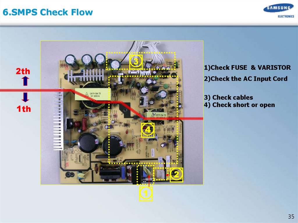
35.
6.SMPS Check Flow2th
3
1)Check FUSE & VARISTOR
2)Check the AC Input Cord
3) Check cables
4) Check short or open
1th
4
2
1
35
36.
7.Deck Assy. AH59-01769A36
37.
7. Mecha Disassemble (MECHA-DECK)1.To Protect PICK-UP, Before detach Flat Cable that point should be shorted.
2. Separate Pick-Up Cable from the Holder
37
38.
7.Mecha Disassemble (MECHA-DECK)2개소
3. Unfasten 2 Screws lift up Holder-Cable
4. Unfasten 4 Screws saparate Traverse-Deck
38
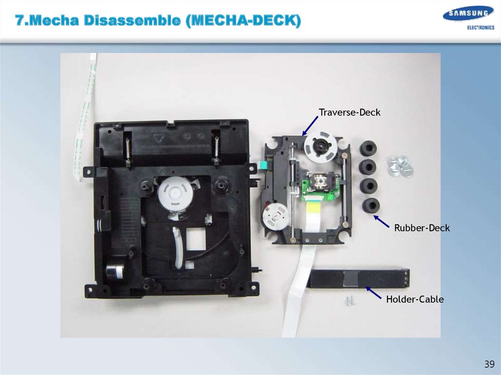
39.
7.Mecha Disassemble (MECHA-DECK)Traverse-Deck
Rubber-Deck
Holder-Cable
39
40.
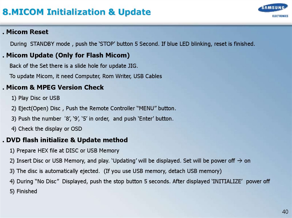
8.MICOM Initialization & Update. Micom Reset
During STANDBY mode , push the ‘STOP’ button 5 Second. If blue LED blinking, reset is finished.
. Micom Update (Only for Flash Micom)
Back of the Set there is a slide hole for update JIG.
To update Micom, it need Computer, Rom Writer, USB Cables
. Micom & MPEG Version Check
1) Play Disc or USB
2) Eject(Open) Disc , Push the Remote Controller “MENU” button.
3) Push the number ‘8’, ‘9’, ‘5’ in order, and push ‘Enter’ button.
4) Check the display or OSD
. DVD flash initialize & Update method
1) Prepare HEX file at DISC or USB Memory
2) Insert Disc or USB Memory, and play. ‘Updating’ will be displayed. Set will be power off on
3) The disc is automatically ejected. (If you use USB memory, detach USB memory)
4) During “No Disc” Displayed, push the stop button 5 seconds. After displayed ‘INITIALIZE’ power off
5) Finished
40
41.
9. Troubleshooting1 . Main
41
42.
9. Troubleshooting2 . Output
42
43.
9. Troubleshooting3 . Circuit Board Layout and Functions
43
44.
9. Troubleshooting44
45.
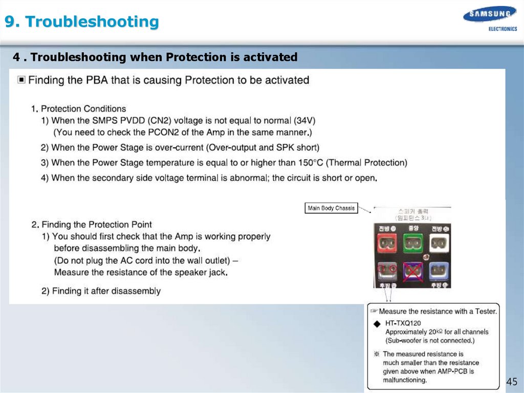
9. Troubleshooting4 . Troubleshooting when Protection is activated
45
46.
9. Troubleshooting46
47.
9. Troubleshooting5 . Troubleshooting HDMI
47
48.
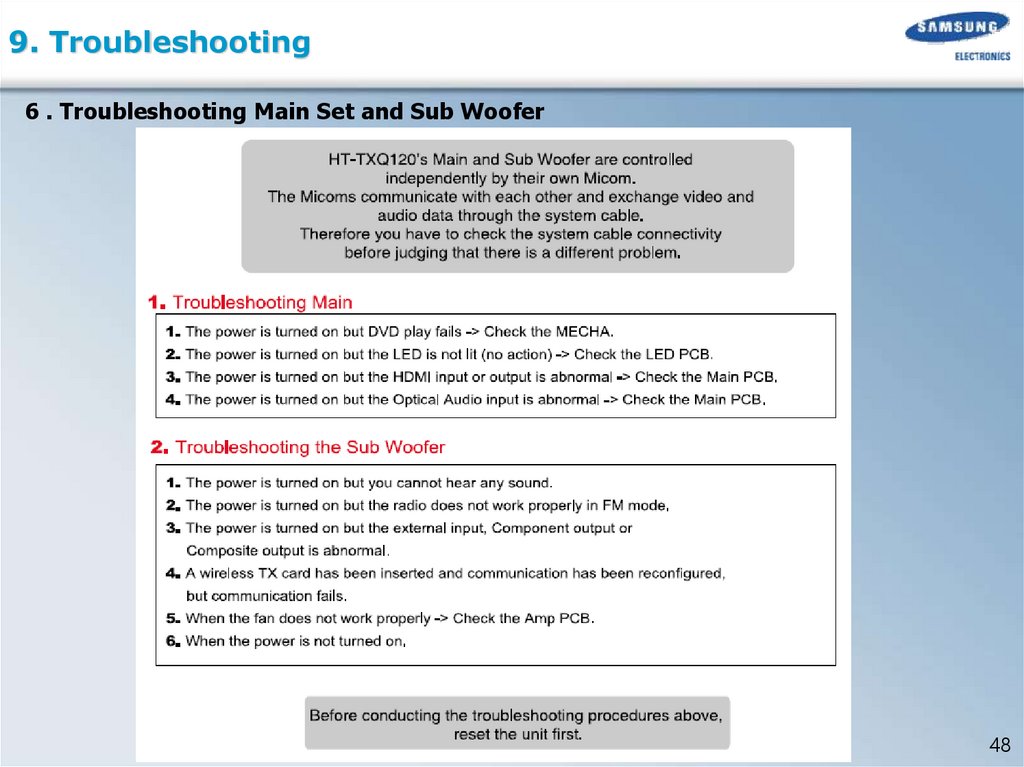
9. Troubleshooting6 . Troubleshooting Main Set and Sub Woofer
48
49.
9. Troubleshooting7 . Communication Failure
1
Sympton
Cause
Check Point
MAIN Working /
No Sound
MICOM-MICOM
Communication Line
open or short
1.SET Reset (MICOM Initialization & Update Page)
2.Check Bellow Points
MAIN PCB
JACK PCB
Pin #12,#13
Pin #7,#8
TX/RX
TXD: #75
RXD: #76
TXD: #75
RXD: #76
49
50.
9. Troubleshooting2
Symptom
Cause
Check Point
SET is not working.
Reset Line problem
Reset Line
(MICOM#79,MPEG#252)
MPEG PART
MICOM PART
UIC1 MICOM
#79 RESET
MIC4 MPEG
#252 RESET
MAIN PCB
JIC1 MICOM
#32 RESET
JACK PCB
SYSTEM RESET
RESET Insecure : It should be 3V after power ON
50
51.
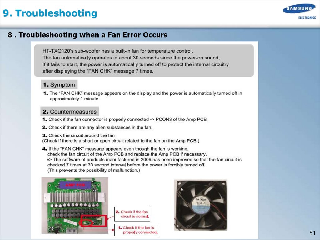
9. Troubleshooting8 . Troubleshooting when a Fan Error Occurs
51
52.
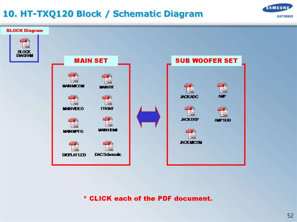
10. HT-TXQ120 Block / Schematic DiagramBLOCK Diagram
MAIN SET
SUB WOOFER SET
* CLICK each of the PDF document.
52