


 Программное обеспечение
Похожие презентации:


")


")


Gemini test process
1. GEMIni test process
GEMINI TEST PROCESSGENERAL KNOWLEDGE
2. Overview Test Process
3. SelfTest Architecture
–
–
–
–
4. Firmware
SF3 FirmwareF3 Firmware
SFW(servo code)
PCO Structure
SAP/RAP …
PCO != Script
PF3 Scripts
CM (Tester)
INC Code
SIC Cell
CPC Code
CPC Cell
5. Platform Firmware and Scripts
6. Process Map
Clean Room
PRE2/CAL2
FNC2
CUT2
FIN2
CRT2
7. Firmware
PRE2• download SF3, SFW/SAP and RAP(HAP).
• Selftest firmware.
FNC2
• Selftest Firmware
CRT2
• download interface firmware codes (F3).
• Customer Firmware
FIN2
• Customer Firmware
CUT2
• Customer Firmware
Adaptive
Parameters
8. Adaptive Parameters
–
–
–
–
9. RAP
Variable Bit Aspect Ratio (VBAR) Read/Write
Adaptive Parameter File
–
– VBAR Configuration File
– Zone Format Budget Parameters File
– Channel Parameters File
10. HAP
HAP consists of the portions of adaptive parameters pertaining to
Heads/Media requirements.
Currently, it captures two sub-files: the Adaptive Fly Height (AFH)
sub-file, and the AFH Adjustment sub-file.
The HAP is a black box to the RAP super file. Space is set aside for
the HAP within the contiguous RAP. The HAP is not separately
downloadable.
The overall space allocation is 7 kilobytes (7168 bytes), to account for
current utilization, plus Dual Heater and DETCR requirements, plus
room to grow.
11. SAP and CAP
12. Firmware folder
All Firmwarecode(Servo, SF3,
F3, CPC SIC…)
CPC Code
VBAR Code
Servo Code
F3 Code
SF3 Code
13. PRE2 Test
–
–
–
–
–
–
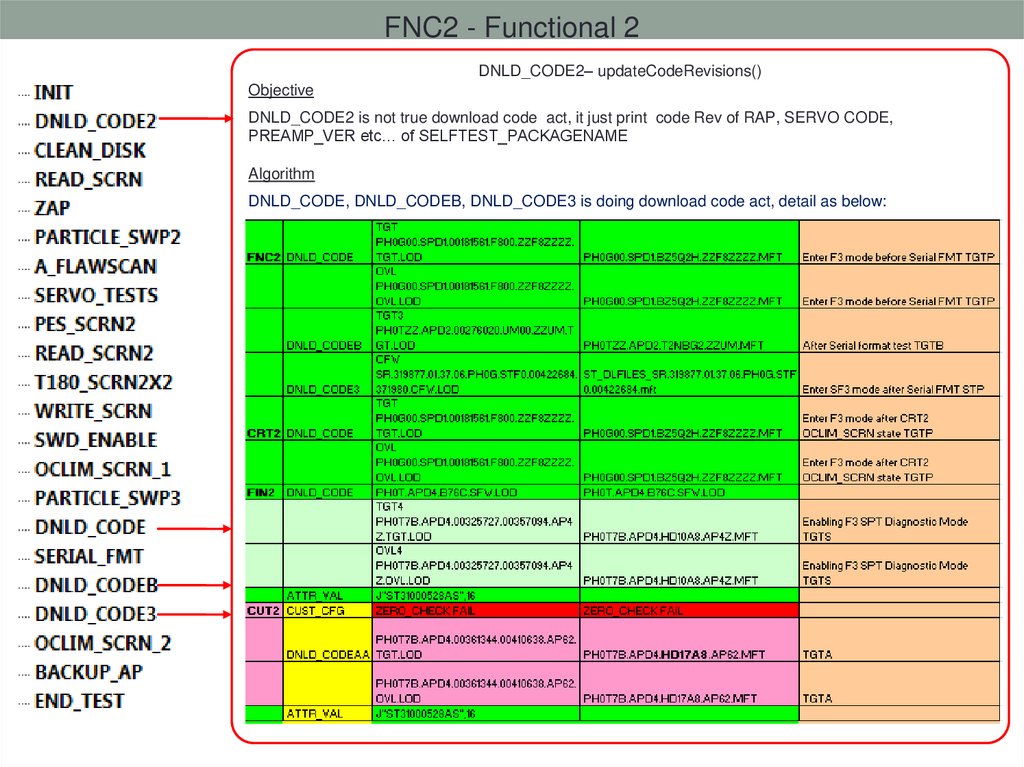
–
–
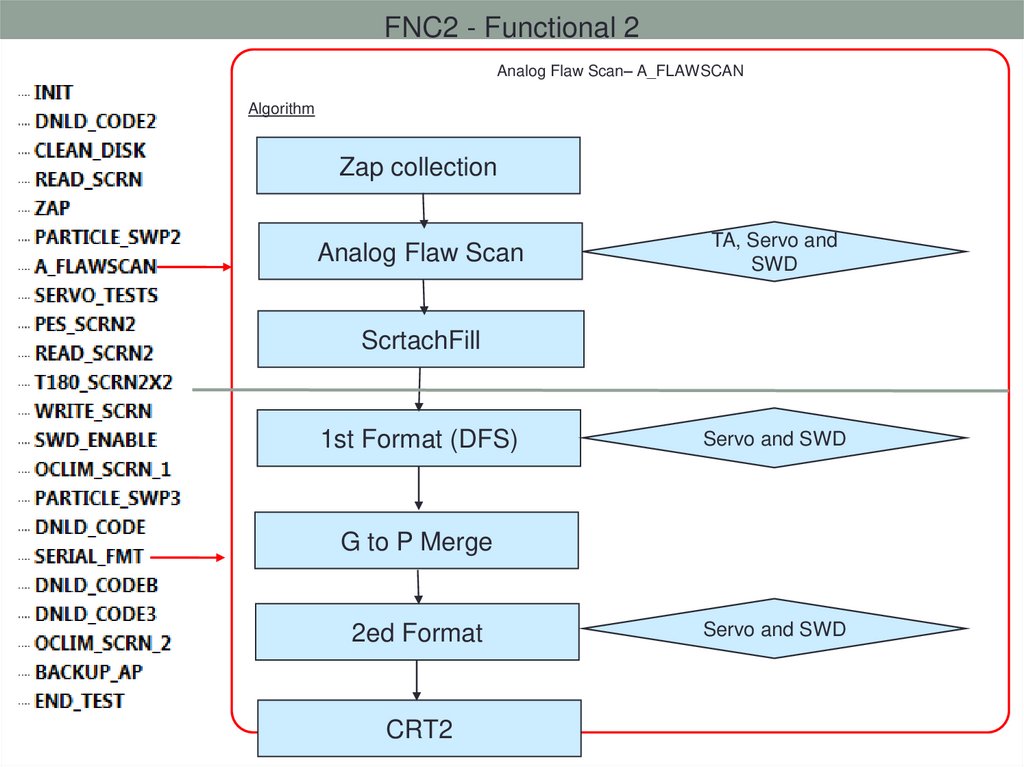
–
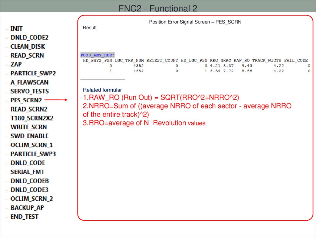
–
–
–
14. PRE2 Test
––
–
–
–
–
–
–
–
–
–
–
15. FNC2 Test
–
–
–
–
–
–
–
–
–
16. CRT2 Test
–
–
–
–
–
–
–
–
–
–
17. FIN2 to CUT2 Test
–
–
–
–
–
–
–
–
18.
Important Self-Test19. Self-Test: Servo Calibrations
–
–
–
–
–
–
20. Self-Test: Servo MDW Calibrations
–
–
–
–
21. Self-Test: Writer to Reader Cals
22. Self-Test: Writer to Reader Cals
TrackSpindle Center
(Skew angle)
Writer-to-reader offset
Reader location
Offset
Writer location
Actuator length
Separation
Actuator pivot
23. Self-Test: Writer to Reader Cals
Position OffsetReader
Gap
Writer
OD Skew
ID Skew
24. Self-Test: Adaptive Fly Height
–
–
25. Self-Test: Adaptive Fly Height
26. Self-Test: VBAR
27. Self-Test: VBAR
BPI =bits per inch (down track direction)TPI =tracks per inch (cross track direction)
BAR = Bit Aspect
Ratio
Cross track (TPI)
= magnetization oriented out of disk plane
= magnetization oriented into disk plane
28. Self-Test: VBAR
–
–
nominal
narrow heads
wide heads
29. Self-Test: Channel Tuning
–
–
–
–
–
–
30. Self-Test: ZAP
–
–
PES
PES
Without ZAP
With ZAP
31. Self-Test: Flaw Scan
–
–
–
–
32. Self-Test: Scratch Fill & Padding
Self-Test: Scratch Fill & Padding1NM02072
24000
23900
23800
23700
23600
23500
23400
23300
0
100000
200000
300000
400000
500000
600000
700000
800000
33. Self-Test: Encroachment Screen
–
o
o
o
34. Self-Test: Encroachment Screen
–
–
–
–
–
Step 1
Step 2
Write
Write
Measure Baseline BER
Measure Baseline BER
Write
Measure Baseline BER
Measure Baseline BER
Measure Encroached BER
Write
Measure Baseline BER
Write
Measure Encroached BER
Write
Measure Baseline BER
Write
Write
Measure Encroached BER
Write
Write
Write
Measure Encroached BER
Write
Write
Write
Measure Encroached BER
Write
Write
Write
Write
Step 4
Write
Write
Write
Step 3
Measure Encroached BER
Write
Measure Baseline BER
Measure Encroached BER
Write
35. Self-Test: Adjacent Track Interference Test
–
–
–
–
36. Self-Test: Flaw Scan
–
–
37.
Gemini Process Detail38.
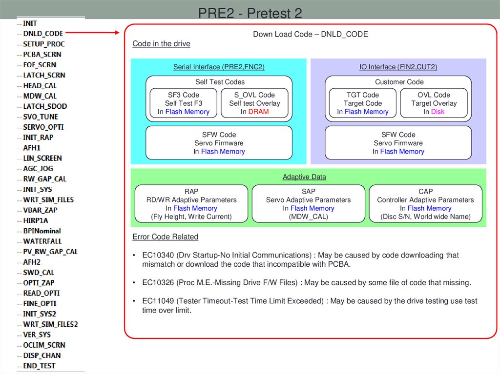
PRE2 - Pretest 2Down Load Code – DNLD_CODE
Code in the drive
Serial Interface (PRE2,FNC2)
IO Interface (FIN2,CUT2)
Self Test Codes
Customer Code
SF3 Code
Self Test F3
In Flash Memory
S_OVL Code
Self test Overlay
In DRAM
TGT Code
Target Code
In Flash Memory
SFW Code
Servo Firmware
In Flash Memory
OVL Code
Target Overlay
In Disk
SFW Code
Servo Firmware
In Flash Memory
Adaptive Data
RAP
RD/WR Adaptive Parameters
In Flash Memory
(Fly Height, Write Current)
SAP
Servo Adaptive Parameters
In Flash Memory
(MDW_CAL)
CAP
Controller Adaptive Parameters
In Flash Memory
(Disc S/N, World wide Name)
Error Code Related
• EC10340 (Drv Startup-No Initial Communications) : May be caused by code downloading that
mismatch or download the code that incompatible with PCBA.
• EC10326 (Proc M.E.-Missing Drive F/W Files) : May be caused by some file of code that missing.
• EC11049 (Tester Timeout-Test Time Limit Exceeded) : May be caused by the drive testing use test
time over limit.
39.
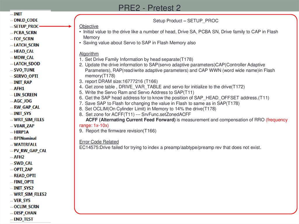
PRE2 - Pretest 2Setup Product – SETUP_PROC
Objective
• Initial value to the drive like a number of head, Drive SA, PCBA SN, Drive family to CAP in Flash
Memory
• Saving value about Servo to SAP in Flash Memory also
Algorithm
1. Set Drive Family Information by head separate(T178)
2. Update the drive information to SAP(servo adaptive parameters)CAP(Controller Adaptive
Parameters), RAP(read/write adaptive parameters) and CAP WWN (word wide name)in Flash
memory(T178)
3. report DRAM size:16777216 (T166)
4. Get zone table , DRIVE_VAR_TABLE and servo for initialize to the drive(T172)
5. Write the Servo Ram and Servo Address to SAP(T11)
6. Get the SAP head address for to know the position of SAP_HEAD_OFFSET address.(T11)
7. Save SAP to Flash for changing the value in Flash to same as in SAP(T178)
8. Set OCLIM(On Cylinder Limit) in Memory to 14% the drive(T178)
8. Set zone for ACFF(T11) --- SrvFunc.setZonedACFF
ACFF (Alternating Current Feed Forward) is measurement and compensation of RRO (frequency
range: 1x-10x)
9. Report the firmware revision(T166)
Error Code Related
EC14575:Drive failed for trying to index a preamp/aabtype/preamp rev that does not exist.
40.
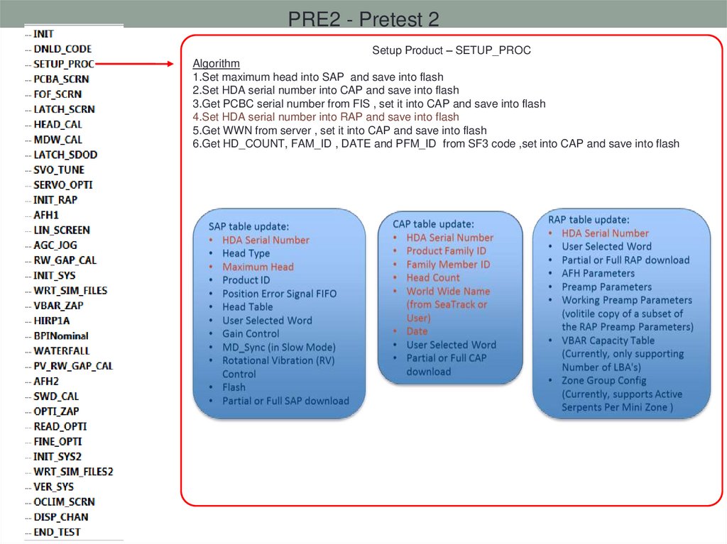
PRE2 - Pretest 2Setup Product – SETUP_PROC
Algorithm
1.Set maximum head into SAP and save into flash
2.Set HDA serial number into CAP and save into flash
3.Get PCBC serial number from FIS , set it into CAP and save into flash
4.Set HDA serial number into RAP and save into flash
5.Get WWN from server , set it into CAP and save into flash
6.Get HD_COUNT, FAM_ID , DATE and PFM_ID from SF3 code ,set into CAP and save into flash
41.
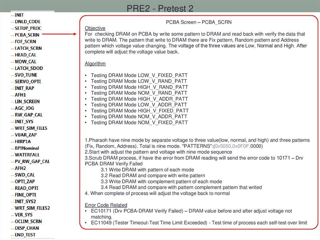
PRE2 - Pretest 2PCBA Screen – PCBA_SCRN
Objective
For checking DRAM on PCBA by write some pattern to DRAM and read back with verify the data that
write to DRAM. The pattern that write to DRAM there are Fix pattern, Random pattern and Address
pattern which voltage value changing. The voltage of the three values are Low, Normal and High. After
complete will adjust the voltage value back.
Algorithm
Testing DRAM Mode LOW_V_FIXED_PATT
Testing DRAM Mode LOW_V_RAND_PATT
Testing DRAM Mode HIGH_V_RAND_PATT
Testing DRAM Mode NOM_V_RAND_PATT
Testing DRAM Mode HIGH_V_ADDR_PATT
Testing DRAM Mode LOW_V_ADDR_PATT
Testing DRAM Mode HIGH_V_FIXED_PATT
Testing DRAM Mode NOM_V_ADDR_PATT
Testing DRAM Mode NOM_V_FIXED_PATT
1.Pharaoh have nine mode by separate voltage to three value(low, normal, and high) and three patterns
(Fix, Random, Address). Total is nine mode. "PATTERNS":(0x5050,0x0F0F,0000)
2.Start with adjust the pattern and voltage with nine mode sequence
3.Scrub DRAM process, if have the error from DRAM reading will send the error code to 10171 – Drv
PCBA DRAM Verify Failed
3.1 Write DRAM with pattern of each mode
3.2 Read DRAM and compare with write pattern
3.3 Write DRAM with complement pattern of each mode
3.4 Read DRAM and compare with pattern complement pattern that writed
4. When complete of process will adjust the voltage back to normal
Error Code Related
• EC10171 (Drv PCBA-DRAM Verify Failed) – DRAM value before and after adjust voltage not
matching.
• EC11049 (Tester Timeout-Test Time Limit Exceeded) - Test time of process each self-test over limit
42.
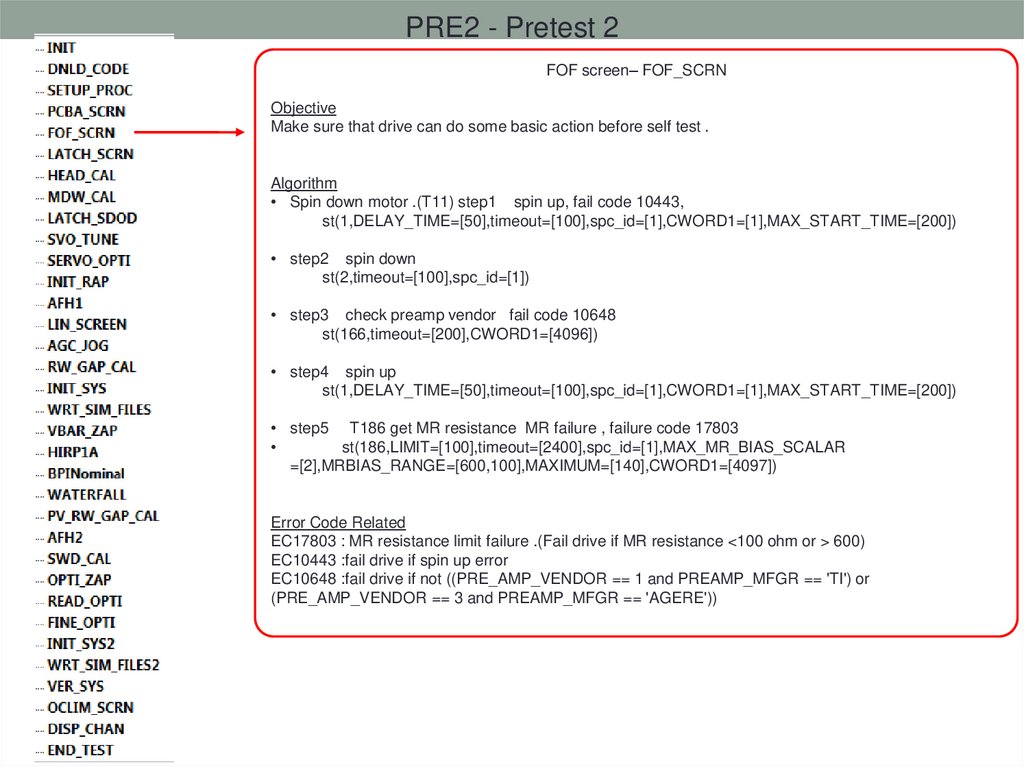
PRE2 - Pretest 2FOF screen– FOF_SCRN
Objective
Make sure that drive can do some basic action before self test .
Algorithm
• Spin down motor .(T11) step1 spin up, fail code 10443,
st(1,DELAY_TIME=[50],timeout=[100],spc_id=[1],CWORD1=[1],MAX_START_TIME=[200])
• step2 spin down
st(2,timeout=[100],spc_id=[1])
• step3 check preamp vendor fail code 10648
st(166,timeout=[200],CWORD1=[4096])
• step4 spin up
st(1,DELAY_TIME=[50],timeout=[100],spc_id=[1],CWORD1=[1],MAX_START_TIME=[200])
• step5 T186 get MR resistance MR failure , failure code 17803
st(186,LIMIT=[100],timeout=[2400],spc_id=[1],MAX_MR_BIAS_SCALAR
=[2],MRBIAS_RANGE=[600,100],MAXIMUM=[140],CWORD1=[4097])
Error Code Related
EC17803 : MR resistance limit failure .(Fail drive if MR resistance <100 ohm or > 600)
EC10443 :fail drive if spin up error
EC10648 :fail drive if not ((PRE_AMP_VENDOR == 1 and PREAMP_MFGR == 'TI') or
(PRE_AMP_VENDOR == 3 and PREAMP_MFGR == 'AGERE'))
43.
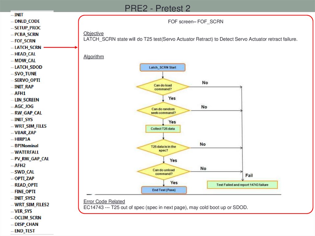
PRE2 - Pretest 2FOF screen– FOF_SCRN
Objective
LATCH_SCRN state will do T25 test(Servo Actuator Retract) to Detect Servo Actuator retract failure.
Algorithm
Error Code Related
EC14743 --- T25 out of spec (spec in next page), may cold boot up or SDOD.
44.
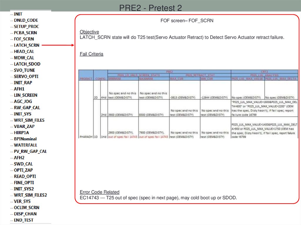
PRE2 - Pretest 2FOF screen– FOF_SCRN
Objective
LATCH_SCRN state will do T25 test(Servo Actuator Retract) to Detect Servo Actuator retract failure.
Fail Criteria
Error Code Related
EC14743 --- T25 out of spec (spec in next page), may cold boot up or SDOD.
45.
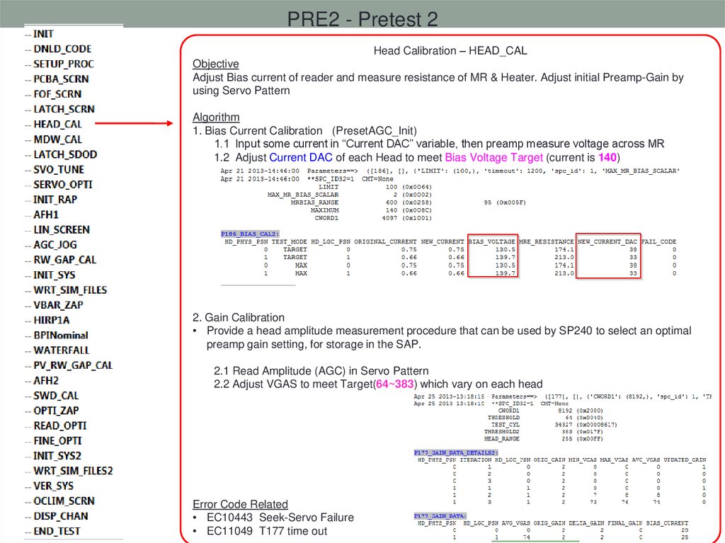
PRE2 - Pretest 2Head Calibration – HEAD_CAL
Objective
Adjust Bias current of reader and measure resistance of MR & Heater. Adjust initial Preamp-Gain by
using Servo Pattern
Algorithm
1. Bias Current Calibration (PresetAGC_Init)
1.1 Input some current in “Current DAC” variable, then preamp measure voltage across MR
1.2 Adjust Current DAC of each Head to meet Bias Voltage Target (current is 140)
2. Gain Calibration
• Provide a head amplitude measurement procedure that can be used by SP240 to select an optimal
preamp gain setting, for storage in the SAP.
2.1 Read Amplitude (AGC) in Servo Pattern
2.2 Adjust VGAS to meet Target(64~383) which vary on each head
Error Code Related
• EC10443 Seek-Servo Failure
• EC11049 T177 time out
46.
PRE2 - Pretest 2MDW Calibration – MDW_CAL
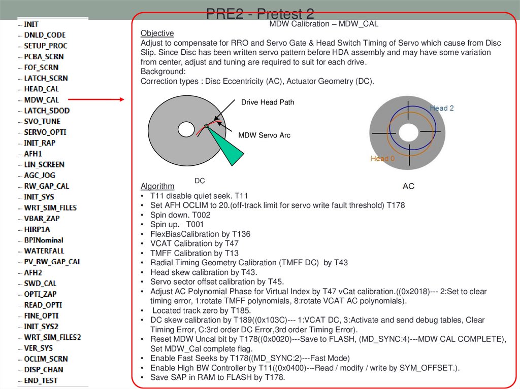
Objective
Adjust to compensate for RRO and Servo Gate & Head Switch Timing of Servo which cause from Disc
Slip. Since Disc has been written servo pattern before HDA assembly and may have some variation
from center, adjust and tuning are required to suit for each drive.
Background:
Correction types : Disc Eccentricity (AC), Actuator Geometry (DC).
Drive Head Path
MDW Servo Arc
DC
Algorithm
• T11 disable quiet seek. T11
• Set AFH OCLIM to 20.(off-track limit for servo write fault threshold) T178
• Spin down. T002
• Spin up. T001
• FlexBiasCalibration by T136
• VCAT Calibration by T47
• TMFF Calibration by T13
• Radial Timing Geometry Calibration (TMFF DC) by T43
• Head skew calibration by T43.
• Servo sector offset calibration by T45.
• Adjust AC Polynomial Phase for Virtual Index by T47 vCat calibration.((0x2018)--- 2:Set to clear
timing error, 1:rotate TMFF polynomials, 8:rotate VCAT AC polynomials).
• Located track zero by T185.
• DC skew calibration by T189((0x103C)--- 1:VCAT DC, 3:Activate and send debug tables, Clear
Timing Error, C:3rd order DC Error,3rd order Timing Error).
• Reset MDW Uncal bit by T178((0x0020)---Save to FLASH, (MD_SYNC:4)---MDW CAL COMPLETE),
Set MDW_Cal complete flag.
• Enable Fast Seeks by T178((MD_SYNC:2)---Fast Mode)
• Enable High BW Controller by T11((0x0400)---Read / modify / write by SYM_OFFSET.).
• Save SAP in RAM to FLASH by T178.
47.
PRE2 - Pretest 2MDW Calibration – MDW_CAL
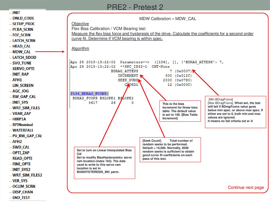
Objective
Flex Bias Calibration / VCM Bearing test
Measure the flex bias force and hysteresis of the drive. Calculate the coefficients for a second order
curve fit. Determine if VCM bearing is within spec.
Algorithm
This is the bias
increment for linear bias
table. The default value
is set to 100. [Bias Table
Increment]
Set to turn on Linear Interpolated Bias
Cal
Set to modify BiasHysteresisInc servo
ram location (index 183). The data
used to write to this servo ram
location is set in
BIASHYSTERESIS_INC parm.
[Min BDragFcons]
[Max BDragFcons], When set, the test
will fail if BDragFcons value goes
below min spec. or above max spec. If
either are set to 0, both min and max
values are ignored.
It means no fail criteria set w/ it
[Seek Count]
Total number of
random seeks to be performed.
Default = 10,000. Normally, 2000
random seeks is sufficient to obtain
good curve fit coefficients on each
pass of this test.
Continue next page
48.
PRE2 - Pretest 2MDW Calibration – MDW_CAL
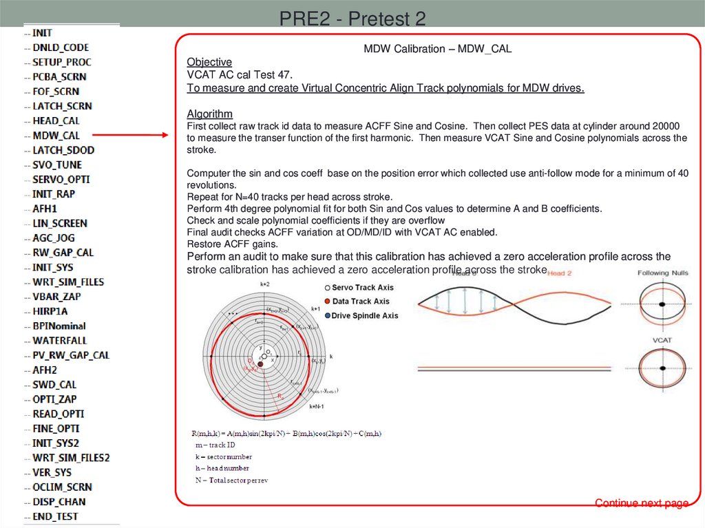
Objective
VCAT AC cal Test 47.
To measure and create Virtual Concentric Align Track polynomials for MDW drives.
Algorithm
First collect raw track id data to measure ACFF Sine and Cosine. Then collect PES data at cylinder around 20000
to measure the transer function of the first harmonic. Then measure VCAT Sine and Cosine polynomials across the
stroke.
Computer the sin and cos coeff base on the position error which collected use anti-follow mode for a minimum of 40
revolutions.
Repeat for N=40 tracks per head across stroke.
Perform 4th degree polynomial fit for both Sin and Cos values to determine A and B coefficients.
Check and scale polynomial coefficients if they are overflow
Final audit checks ACFF variation at OD/MD/ID with VCAT AC enabled.
Restore ACFF gains.
Perform an audit to make sure that this calibration has achieved a zero acceleration profile across the
stroke calibration has achieved a zero acceleration profile across the stroke
Continue next page
49.
PRE2 - Pretest 2MDW Calibration – MDW_CAL
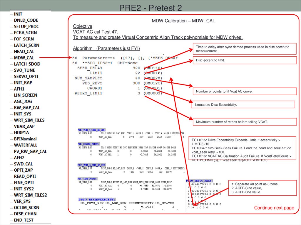
Objective
VCAT AC cal Test 47.
To measure and create Virtual Concentric Align Track polynomials for MDW drives.
Algorithm (Parameters just FYI)
Time to delay after sync demod process used in disc eccentric
measurement.
Disc eccentric limit.
Number of points to fit Vcat AC curve.
1:measure Disc Eccentricity.
Maximum number of retries before failing VCAT.
EC11215: Drive Eccentricity Exceeds Limit. If eccentricity >
LIMIT(6)/10 .
EC10247: Svo Seek-Seek Failure. Load the head and seek err, do
vcat_seek retry > 100.
EC11216: VCAT AC Calibration Audit Failure. If VcatRetryCount >
RETRY_LIMIT(3), If vcat seek fail(ACFF>LIMIT32).
1. Separate 40 point as 8 zone,
2. ACFF-Sine value,
3. ACFF-Cos value
Continue next page
50.
PRE2 - Pretest 2MDW Calibration – MDW_CAL
Objective
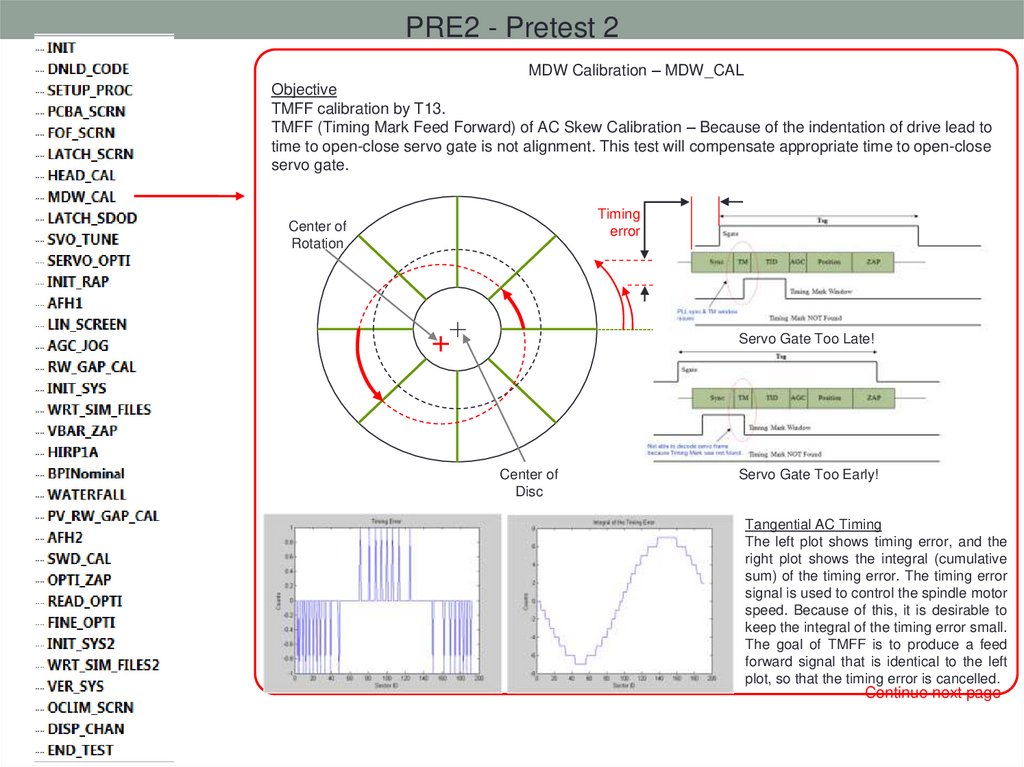
TMFF calibration by T13.
TMFF (Timing Mark Feed Forward) of AC Skew Calibration – Because of the indentation of drive lead to
time to open-close servo gate is not alignment. This test will compensate appropriate time to open-close
servo gate.
Timing
error
Center of
Rotation
Servo Gate Too Late!
Center of
Disc
Servo Gate Too Early!
Tangential AC Timing
The left plot shows timing error, and the
right plot shows the integral (cumulative
sum) of the timing error. The timing error
signal is used to control the spindle motor
speed. Because of this, it is desirable to
keep the integral of the timing error small.
The goal of TMFF is to produce a feed
forward signal that is identical to the left
plot, so that the timing error is cancelled.
Continue next page
51.
PRE2 - Pretest 2MDW Calibration – MDW_CAL
Objective
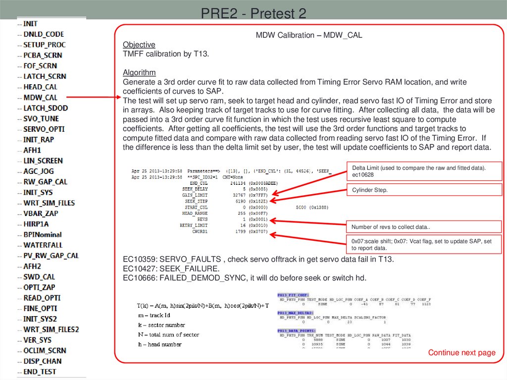
TMFF calibration by T13.
Algorithm
Generate a 3rd order curve fit to raw data collected from Timing Error Servo RAM location, and write
coefficients of curves to SAP.
The test will set up servo ram, seek to target head and cylinder, read servo fast IO of Timing Error and store
in arrays. Also keeping track of target tracks to use for curve fitting. After collecting all data, the data will be
passed into a 3rd order curve fit function in which the test uses recursive least square to compute
coefficients. After getting all coefficients, the test will use the 3rd order functions and target tracks to
compute fitted data and compare with raw data collected from reading servo fast IO of the Timing Error. If
the difference is less than the delta limit set by user, the test will update coefficients to SAP and report data.
Delta Limit (used to compare the raw and fitted data).
ec10628
Cylinder Step.
Number of revs to collect data..
0x07:scale shift; 0x07: Vcat flag, set to update SAP, set
to report data.
EC10359: SERVO_FAULTS , check servo offtrack in get servo data fail in T13.
EC10427: SEEK_FAILURE.
EC10666: FAILED_DEMOD_SYNC, it will do before seek or switch hd.
Continue next page
52.
PRE2 - Pretest 2MDW Calibration – MDW_CAL
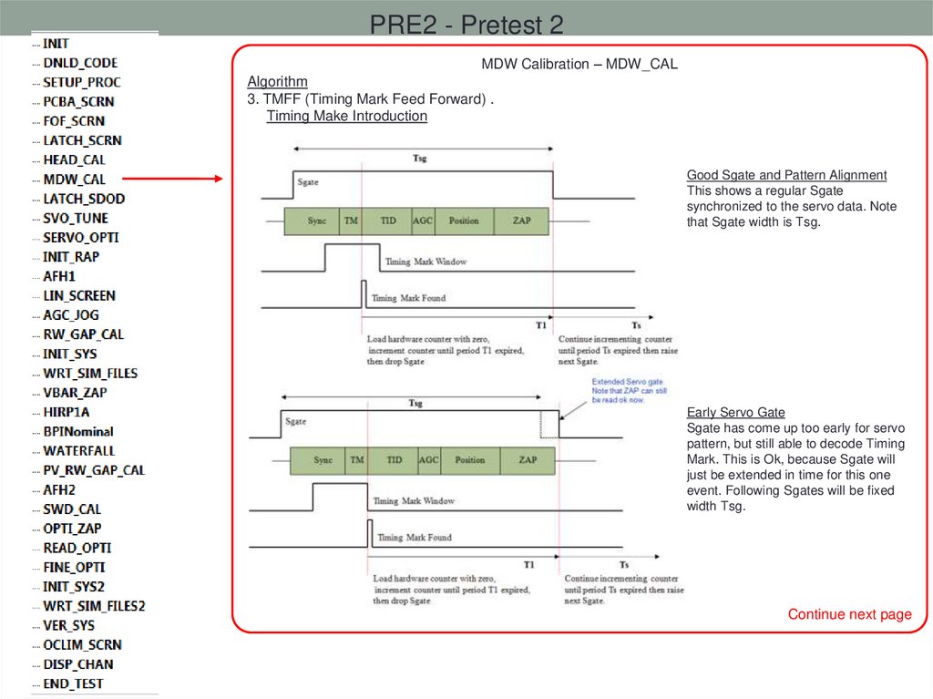
Algorithm
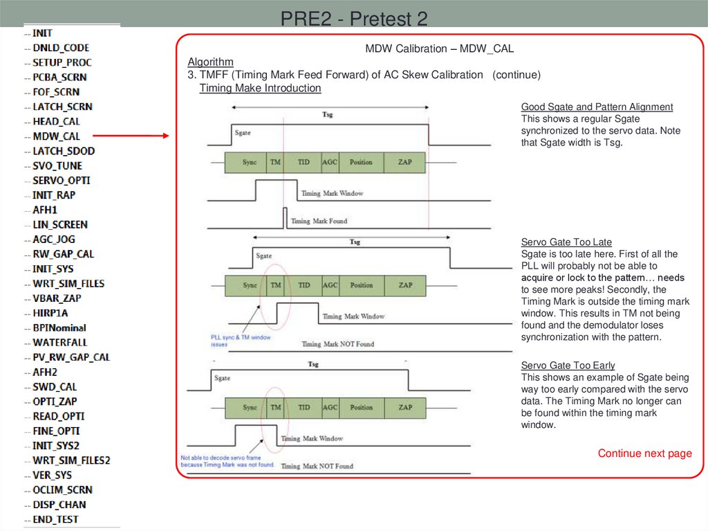
3. TMFF (Timing Mark Feed Forward) .
Timing Make Introduction
Good Sgate and Pattern Alignment
This shows a regular Sgate
synchronized to the servo data. Note
that Sgate width is Tsg.
Early Servo Gate
Sgate has come up too early for servo
pattern, but still able to decode Timing
Mark. This is Ok, because Sgate will
just be extended in time for this one
event. Following Sgates will be fixed
width Tsg.
Continue next page
53.
PRE2 - Pretest 2MDW Calibration – MDW_CAL
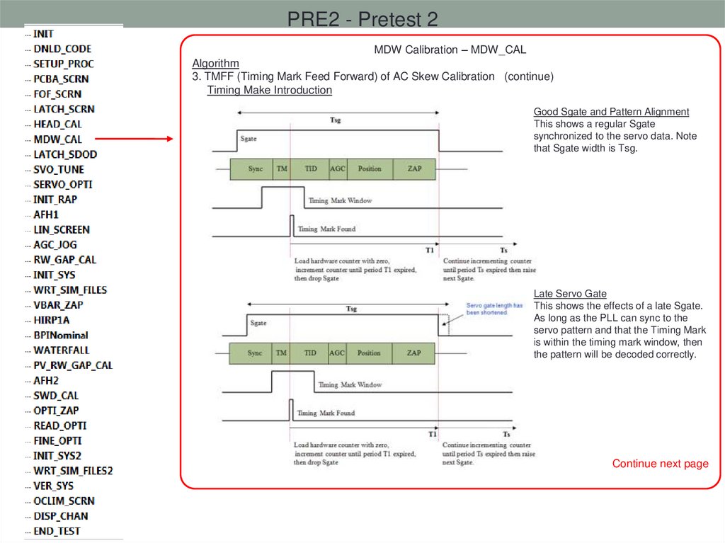
Algorithm
3. TMFF (Timing Mark Feed Forward) of AC Skew Calibration (continue)
Timing Make Introduction
Good Sgate and Pattern Alignment
This shows a regular Sgate
synchronized to the servo data. Note
that Sgate width is Tsg.
Late Servo Gate
This shows the effects of a late Sgate.
As long as the PLL can sync to the
servo pattern and that the Timing Mark
is within the timing mark window, then
the pattern will be decoded correctly.
Continue next page
54.
PRE2 - Pretest 2MDW Calibration – MDW_CAL
Algorithm
3. TMFF (Timing Mark Feed Forward) of AC Skew Calibration (continue)
Timing Make Introduction
Good Sgate and Pattern Alignment
This shows a regular Sgate
synchronized to the servo data. Note
that Sgate width is Tsg.
Servo Gate Too Late
Sgate is too late here. First of all the
PLL will probably not be able to
acquire or lock to the pattern… needs
to see more peaks! Secondly, the
Timing Mark is outside the timing mark
window. This results in TM not being
found and the demodulator loses
synchronization with the pattern.
Servo Gate Too Early
This shows an example of Sgate being
way too early compared with the servo
data. The Timing Mark no longer can
be found within the timing mark
window.
Continue next page
55.
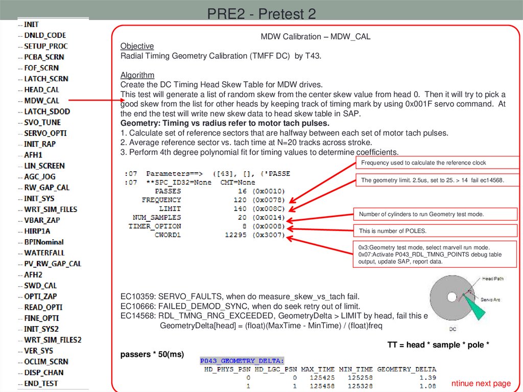
PRE2 - Pretest 2MDW Calibration – MDW_CAL
Objective
Radial Timing Geometry Calibration (TMFF DC) by T43.
Algorithm
Create the DC Timing Head Skew Table for MDW drives.
This test will generate a list of random skew from the center skew value from head 0. Then it will try to pick a
good skew from the list for other heads by keeping track of timing mark by using 0x001F servo command. At
the end the test will write new skew data to head skew table in SAP.
Geometry: Timing vs radius refer to motor tach pulses.
1. Calculate set of reference sectors that are halfway between each set of motor tach pulses.
2. Average reference sector vs. tach time at N=20 tracks across stroke.
3. Perform 4th degree polynomial fit for timing values to determine coefficients.
Frequency used to calculate the reference clock
The geometry limit. 2.5us, set to 25. > 14 fail ec14568.
Number of cylinders to run Geometry test mode.
This is number of POLES.
0x3:Geometry test mode, select marvell run mode.
0x07:Activate P043_RDL_TMNG_POINTS debug table
output, update SAP, report data.
EC10359: SERVO_FAULTS, when do measure_skew_vs_tach fail.
EC10666: FAILED_DEMOD_SYNC, when do seek retry out of limit.
EC14568: RDL_TMNG_RNG_EXCEEDED, GeometryDelta > LIMIT by head, fail this error.
GeometryDelta[head] = (float)(MaxTime - MinTime) / (float)freq
TT = head * sample * pole *
passers * 50(ms)
Continue next page
56.
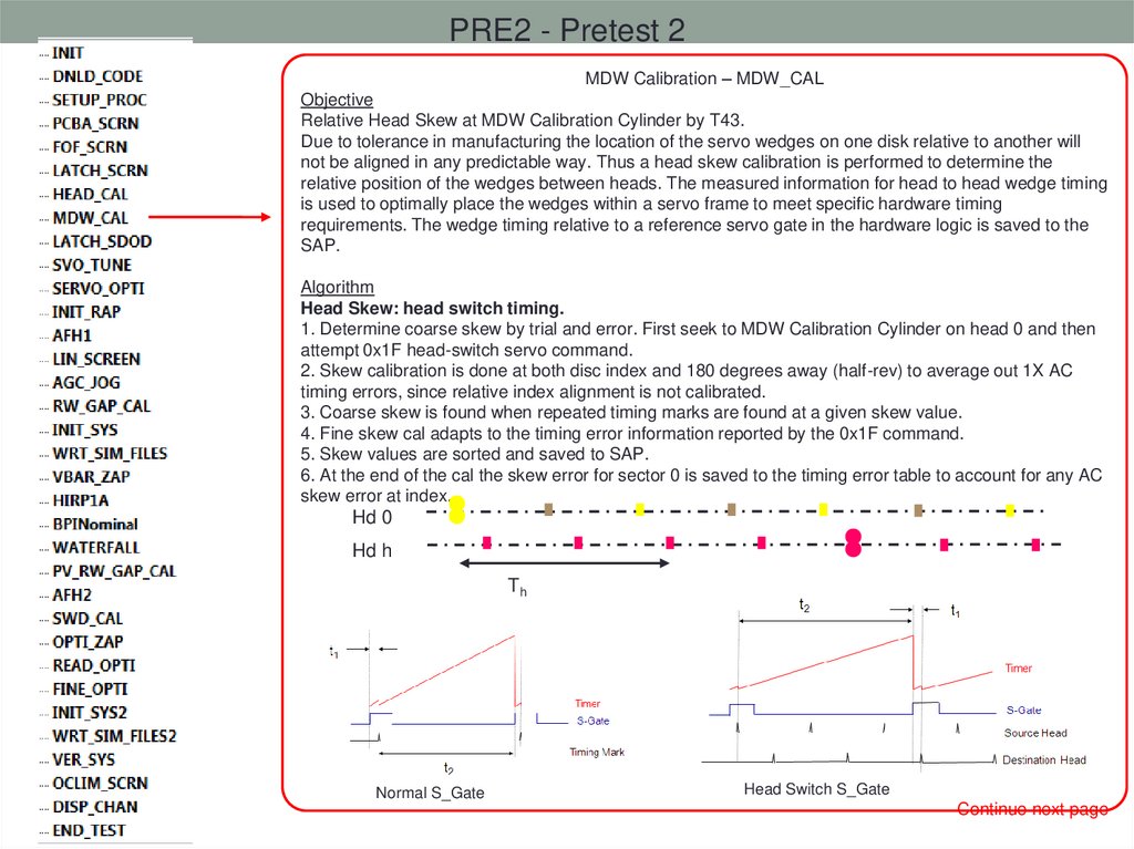
PRE2 - Pretest 2MDW Calibration – MDW_CAL
Objective
Relative Head Skew at MDW Calibration Cylinder by T43.
Due to tolerance in manufacturing the location of the servo wedges on one disk relative to another will
not be aligned in any predictable way. Thus a head skew calibration is performed to determine the
relative position of the wedges between heads. The measured information for head to head wedge timing
is used to optimally place the wedges within a servo frame to meet specific hardware timing
requirements. The wedge timing relative to a reference servo gate in the hardware logic is saved to the
SAP.
Algorithm
Head Skew: head switch timing.
1. Determine coarse skew by trial and error. First seek to MDW Calibration Cylinder on head 0 and then
attempt 0x1F head-switch servo command.
2. Skew calibration is done at both disc index and 180 degrees away (half-rev) to average out 1X AC
timing errors, since relative index alignment is not calibrated.
3. Coarse skew is found when repeated timing marks are found at a given skew value.
4. Fine skew cal adapts to the timing error information reported by the 0x1F command.
5. Skew values are sorted and saved to SAP.
6. At the end of the cal the skew error for sector 0 is saved to the timing error table to account for any AC
skew error at index.
Hd 0
Hd h
Th
Normal S_Gate
Head Switch S_Gate
Continue next page
57.
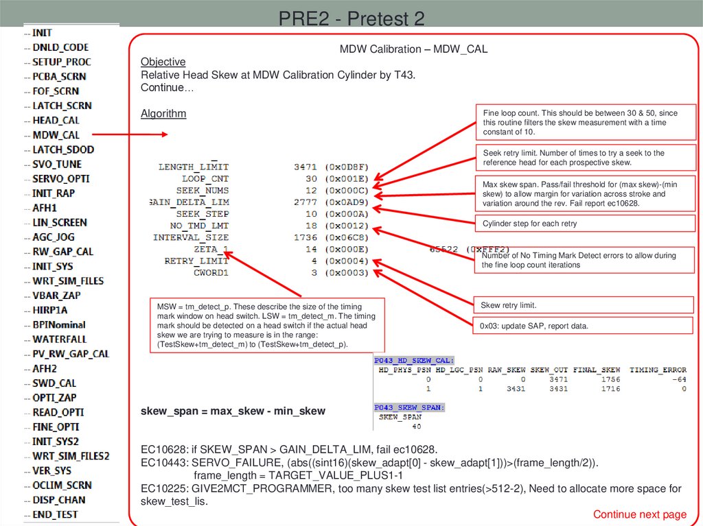
PRE2 - Pretest 2MDW Calibration – MDW_CAL
Objective
Relative Head Skew at MDW Calibration Cylinder by T43.
Continue…
Algorithm
Fine loop count. This should be between 30 & 50, since
this routine filters the skew measurement with a time
constant of 10.
Seek retry limit. Number of times to try a seek to the
reference head for each prospective skew.
Max skew span. Pass/fail threshold for (max skew)-(min
skew) to allow margin for variation across stroke and
variation around the rev. Fail report ec10628.
Cylinder step for each retry
Number of No Timing Mark Detect errors to allow during
the fine loop count iterations
MSW = tm_detect_p. These describe the size of the timing
mark window on head switch. LSW = tm_detect_m. The timing
mark should be detected on a head switch if the actual head
skew we are trying to measure is in the range:
(TestSkew+tm_detect_m) to (TestSkew+tm_detect_p).
Skew retry limit.
0x03: update SAP, report data.
skew_span = max_skew - min_skew
EC10628: if SKEW_SPAN > GAIN_DELTA_LIM, fail ec10628.
EC10443: SERVO_FAILURE, (abs((sint16)(skew_adapt[0] - skew_adapt[1]))>(frame_length/2)).
frame_length = TARGET_VALUE_PLUS1-1
EC10225: GIVE2MCT_PROGRAMMER, too many skew test list entries(>512-2), Need to allocate more space for
skew_test_lis.
Continue next page
58.
PRE2 - Pretest 2MDW Calibration – MDW_CAL
Objective
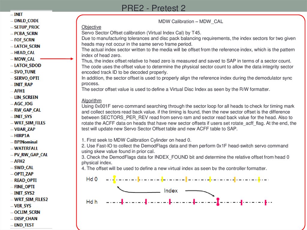
Servo Sector Offset calibration (Virtual Index Cal) by T45.
Due to manufacturing tolerances and disc pack balancing requirements, the index sectors for two given
heads may not occur in the same servo frame period.
The actual index sector written to the media will be offset from the reference index, which is the pattern
index of head zero.
Thus, the index offset relative to head zero is measured and saved to SAP in terms of a sector count.
The code uses the offset value to determine the physical sector count to allow the data integrity sector
encoded track ID to be decoded properly.
In addition, the sector offset is used to properly align the reference index during the demodulator sync
process.
The sector offset value is used to define a Virtual Disc Index as seen by the R/W formatter.
Algorithm
Using 0x001F servo command searching through the sector loop for all heads to check for timing mark
and collect sectors read back value. if the timing is found, then the new sector offset is the difference
between SECTORS_PER_REV read from servo ram and sector read back value for the head. Also to
rotate the ACFF data on heads that have new sector offsets if users set rotate_acff_flag. At the end, the
test will update new Servo Sector Offset table and new ACFF table to SAP.
1. First seek to MDW Calibration Cylinder on head 0.
2. Use Fast-IO to collect the DemodFlags data and then perform 0x1F head-switch servo command
using skew value found in prior cal.
3. Check the DemodFlags data for INDEX_FOUND bit and determine the relative offset from head 0
physical index.
4. The offset will be used to define a new virtual index as seen by the controller formatter.
5. Save the relative sector offset value to SAP.
59.
PRE2 - Pretest 2MDW Calibration – MDW_CAL
Objective
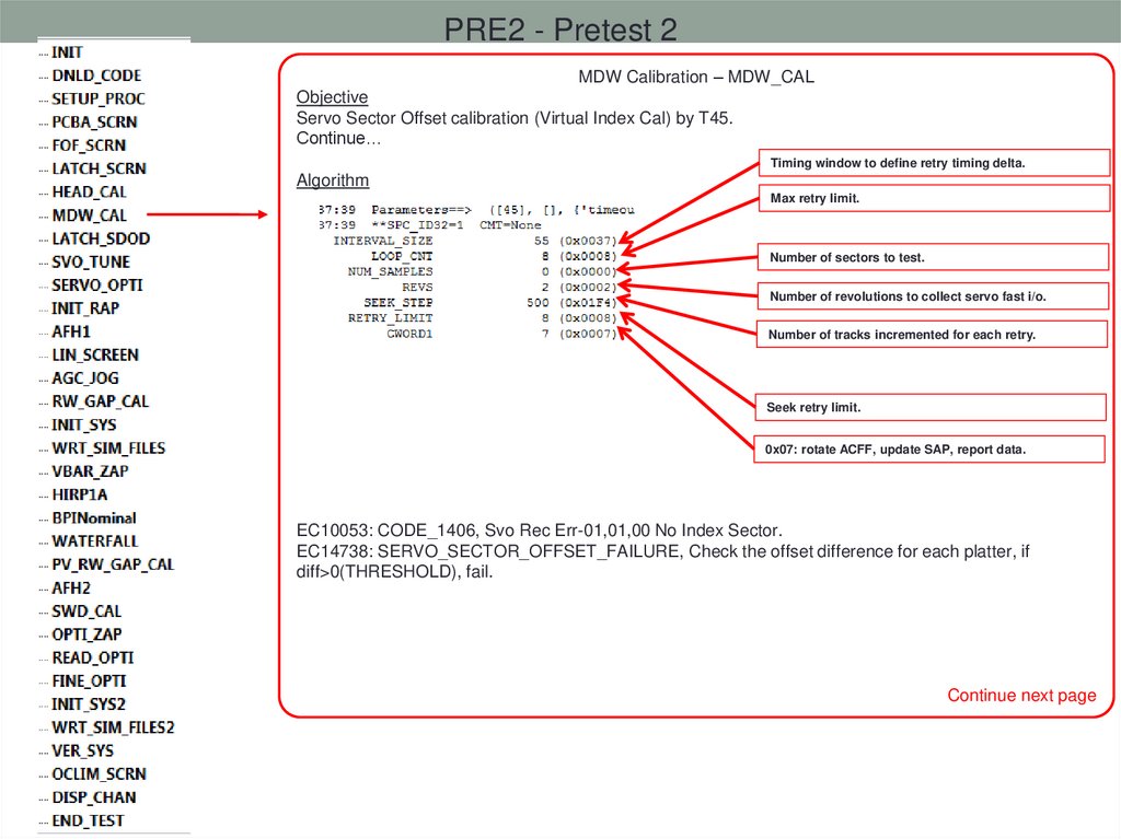
Servo Sector Offset calibration (Virtual Index Cal) by T45.
Continue…
Timing window to define retry timing delta.
Algorithm
Max retry limit.
Number of sectors to test.
Number of revolutions to collect servo fast i/o.
Number of tracks incremented for each retry.
Seek retry limit.
0x07: rotate ACFF, update SAP, report data.
EC10053: CODE_1406, Svo Rec Err-01,01,00 No Index Sector.
EC14738: SERVO_SECTOR_OFFSET_FAILURE, Check the offset difference for each platter, if
diff>0(THRESHOLD), fail.
Continue next page
60.
PRE2 - Pretest 2MDW Calibration – MDW_CAL
Objective
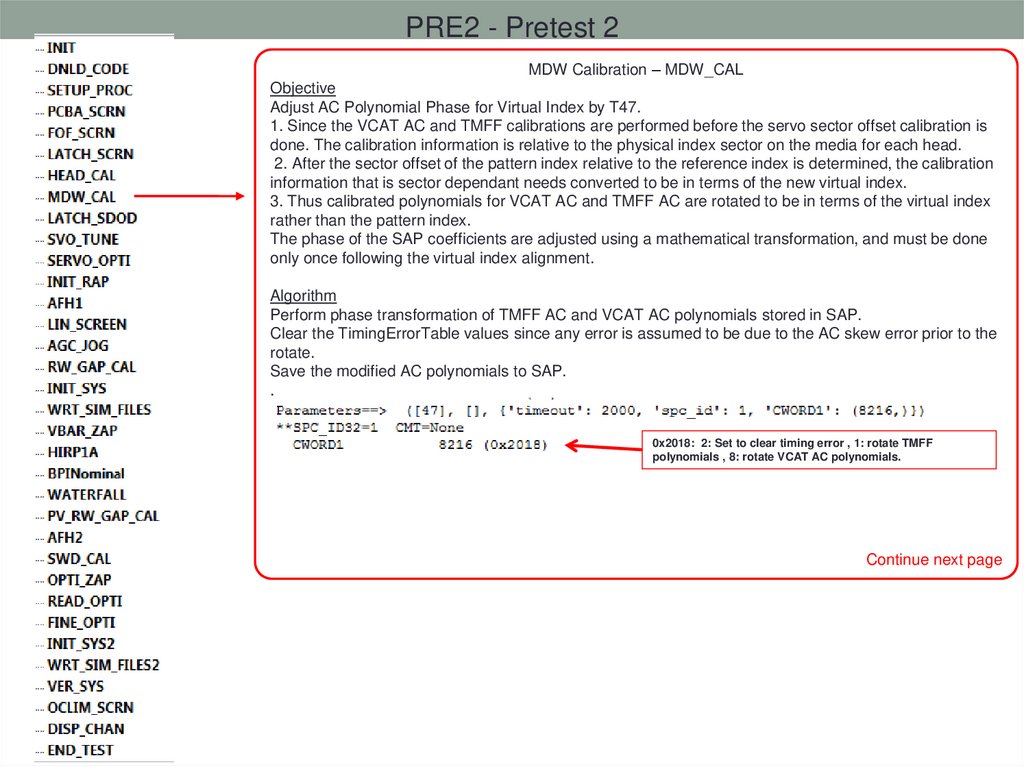
Adjust AC Polynomial Phase for Virtual Index by T47.
1. Since the VCAT AC and TMFF calibrations are performed before the servo sector offset calibration is
done. The calibration information is relative to the physical index sector on the media for each head.
2. After the sector offset of the pattern index relative to the reference index is determined, the calibration
information that is sector dependant needs converted to be in terms of the new virtual index.
3. Thus calibrated polynomials for VCAT AC and TMFF AC are rotated to be in terms of the virtual index
rather than the pattern index.
The phase of the SAP coefficients are adjusted using a mathematical transformation, and must be done
only once following the virtual index alignment.
Algorithm
Perform phase transformation of TMFF AC and VCAT AC polynomials stored in SAP.
Clear the TimingErrorTable values since any error is assumed to be due to the AC skew error prior to the
rotate.
Save the modified AC polynomials to SAP.
.
0x2018: 2: Set to clear timing error , 1: rotate TMFF
polynomials , 8: rotate VCAT AC polynomials.
Continue next page
61.
PRE2 - Pretest 2MDW Calibration – MDW_CAL
Objective
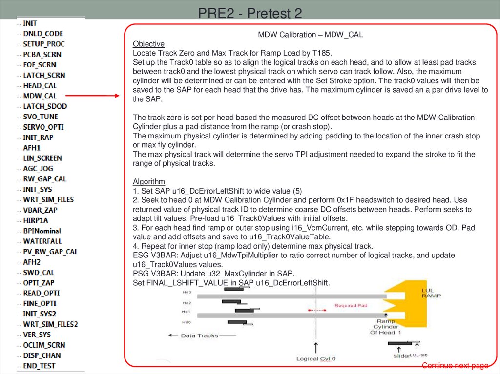
Locate Track Zero and Max Track for Ramp Load by T185.
Set up the Track0 table so as to align the logical tracks on each head, and to allow at least pad tracks
between track0 and the lowest physical track on which servo can track follow. Also, the maximum
cylinder will be determined or can be entered with the Set Stroke option. The track0 values will then be
saved to the SAP for each head that the drive has. The maximum cylinder is saved an a per drive level to
the SAP.
The track zero is set per head based the measured DC offset between heads at the MDW Calibration
Cylinder plus a pad distance from the ramp (or crash stop).
The maximum physical cylinder is determined by adding padding to the location of the inner crash stop
or max fly cylinder.
The max physical track will determine the servo TPI adjustment needed to expand the stroke to fit the
range of physical tracks.
Algorithm
1. Set SAP u16_DcErrorLeftShift to wide value (5)
2. Seek to head 0 at MDW Calibration Cylinder and perform 0x1F headswitch to desired head. Use
returned value of physical track ID to determine coarse DC offsets between heads. Perform seeks to
adapt tilt values. Pre-load u16_Track0Values with initial offsets.
3. For each head find ramp or outer stop using i16_VcmCurrent, etc. while stepping towards OD. Pad
value and add offsets and save to u16_Track0ValueTable.
4. Repeat for inner stop (ramp load only) determine max physical track.
ESG V3BAR: Adjust u16_MdwTpiMultiplier to ratio correct number of logical tracks, and update
u16_Track0Values values.
PSG V3BAR: Update u32_MaxCylinder in SAP.
Set FINAL_LSHIFT_VALUE in SAP u16_DcErrorLeftShift.
Continue next page
62.
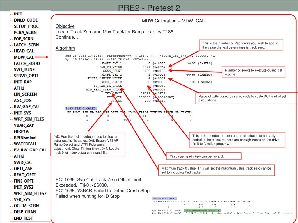
PRE2 - Pretest 2MDW Calibration – MDW_CAL
Objective
Locate Track Zero and Max Track for Ramp Load by T185.
Continue…
Algorithm
.
This is the number of Pad tracks you wish to add to
the value the test determines is track zero.
Number of seeks to execute during cal
routine
Value of LShift used by servo code to scale DC head offset
calculations.
0x8: Run the test in debug mode to display
extra results file tables, 0x5: Enable V3BAR
Ramp Detect and VTPI Polynomial
adjustment, Clear Timing Error . 0x4: Locate
track 0 with servodiag command 1f .
This is the number of extra pad tracks that is temporarily
added to tk0 to insure there are enough tracks on the drive
for it to function properly.
Min value head skew can be, invalid.
Maximum track 0 value. This will set the maximum value track zero can be
set to including Pad tracks.
EC11036: Svo Cal-Track Zero Offset Limit
Exceeded. Trk0 > 26000.
EC14669: V3BAR Failed to Detect Crash Stop.
Failed when hunting for ID Stop.
63.
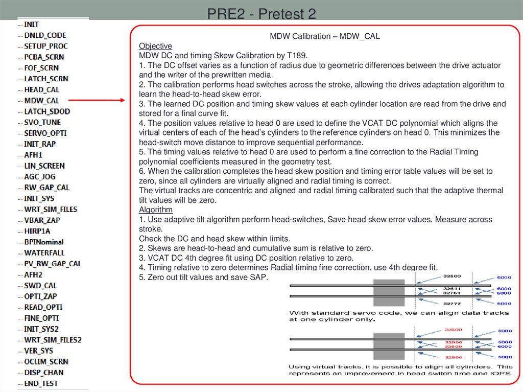
PRE2 - Pretest 2MDW Calibration – MDW_CAL
Objective
MDW DC and timing Skew Calibration by T189.
1. The DC offset varies as a function of radius due to geometric differences between the drive actuator
and the writer of the prewritten media.
2. The calibration performs head switches across the stroke, allowing the drives adaptation algorithm to
learn the head-to-head skew error.
3. The learned DC position and timing skew values at each cylinder location are read from the drive and
stored for a final curve fit.
4. The position values relative to head 0 are used to define the VCAT DC polynomial which aligns the
virtual centers of each of the head’s cylinders to the reference cylinders on head 0. This minimizes the
head-switch move distance to improve sequential performance.
5. The timing values relative to head 0 are used to perform a fine correction to the Radial Timing
polynomial coefficients measured in the geometry test.
6. When the calibration completes the head skew position and timing error table values will be set to
zero, since all cylinders are virtually aligned and radial timing is correct.
The virtual tracks are concentric and aligned and radial timing calibrated such that the adaptive thermal
tilt values will be zero.
Algorithm
1. Use adaptive tilt algorithm perform head-switches, Save head skew error values. Measure across
stroke.
Check the DC and head skew within limits.
2. Skews are head-to-head and cumulative sum is relative to zero.
3. VCAT DC 4th degree fit using DC position relative to zero.
4. Timing relative to zero determines Radial timing fine correction, use 4th degree fit.
5. Zero out tilt values and save SAP.
64.
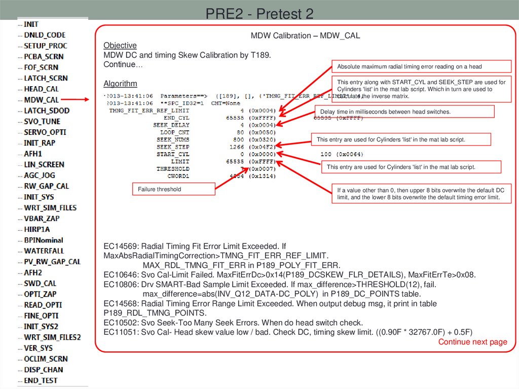
PRE2 - Pretest 2MDW Calibration – MDW_CAL
Objective
MDW DC and timing Skew Calibration by T189.
Continue…
Absolute maximum radial timing error reading on a head
This entry along with START_CYL and SEEK_STEP are used for
Cylinders 'list' in the mat lab script. Which in turn are used to
calculate the inverse matrix.
Algorithm
.
Delay time in milliseconds between head switches.
This entry are used for Cylinders 'list' in the mat lab script.
This entry are used for Cylinders 'list' in the mat lab script.
Failure threshold
If a value other than 0, then upper 8 bits overwrite the default DC
limit, and the lower 8 bits overwrite the default timing error limit.
EC14569: Radial Timing Fit Error Limit Exceeded. If
MaxAbsRadialTimingCorrection>TMNG_FIT_ERR_REF_LIMIT.
MAX_RDL_TMNG_FIT_ERR in P189_POLY_FIT_ERR.
EC10646: Svo Cal-Limit Failed. MaxFitErrDc>0x14(P189_DCSKEW_FLR_DETAILS), MaxFitErrTe>0x08.
EC10806: Drv SMART-Bad Sample Limit Exceeded. If max_difference>THRESHOLD(12), fail.
max_difference=abs(INV_Q12_DATA-DC_POLY) in P189_DC_POINTS table.
EC14568: Radial Timing Error Range Limit Exceeded. When output debug msg, it print in table
P189_RDL_TMNG_POINTS.
EC10502: Svo Seek-Too Many Seek Errors. When do head switch check.
EC11051: Svo Cal- Head skew value low / bad. Check DC, timing skew limit. ((0.90F * 32767.0F) + 0.5F)
Continue next page
65.
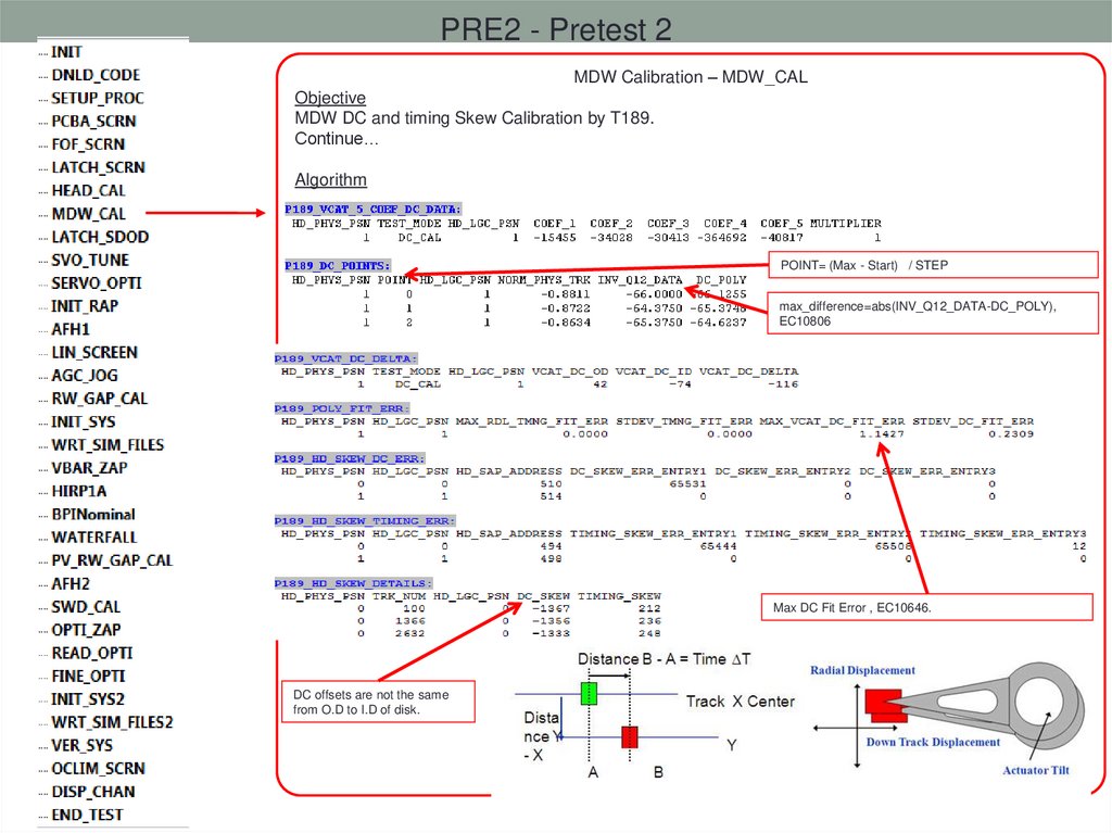
PRE2 - Pretest 2MDW Calibration – MDW_CAL
Objective
MDW DC and timing Skew Calibration by T189.
Continue…
Algorithm
.
POINT= (Max - Start) / STEP
max_difference=abs(INV_Q12_DATA-DC_POLY),
EC10806
Max DC Fit Error , EC10646.
DC offsets are not the same
from O.D to I.D of disk.
Continue next page
66.
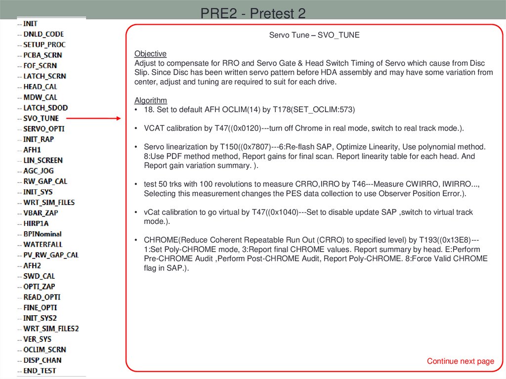
PRE2 - Pretest 2Servo Tune – SVO_TUNE
Objective
Adjust to compensate for RRO and Servo Gate & Head Switch Timing of Servo which cause from Disc
Slip. Since Disc has been written servo pattern before HDA assembly and may have some variation from
center, adjust and tuning are required to suit for each drive.
Algorithm
• 18. Set to default AFH OCLIM(14) by T178(SET_OCLIM:573)
• VCAT calibration by T47((0x0120)---turn off Chrome in real mode, switch to real track mode.).
• Servo linearization by T150((0x7807)---6:Re-flash SAP, Optimize Linearity, Use polynomial method.
8:Use PDF method method, Report gains for final scan. Report linearity table for each head. And
Report gain variation summary. ).
• test 50 trks with 100 revolutions to measure CRRO,IRRO by T46---Measure CWIRRO, IWIRRO...,
Selecting this measurement changes the PES data collection to use Observer Position Error.).
• vCat calibration to go virtual by T47((0x1040)---Set to disable update SAP ,switch to virtual track
mode.).
• CHROME(Reduce Coherent Repeatable Run Out (CRRO) to specified level) by T193((0x13E8)--1:Set Poly-CHROME mode, 3:Report final CHROME values. Report summary by head. E:Perform
Pre-CHROME Audit ,Perform Post-CHROME Audit, Report Poly-CHROME. 8:Force Valid CHROME
flag in SAP.).
Continue next page
67.
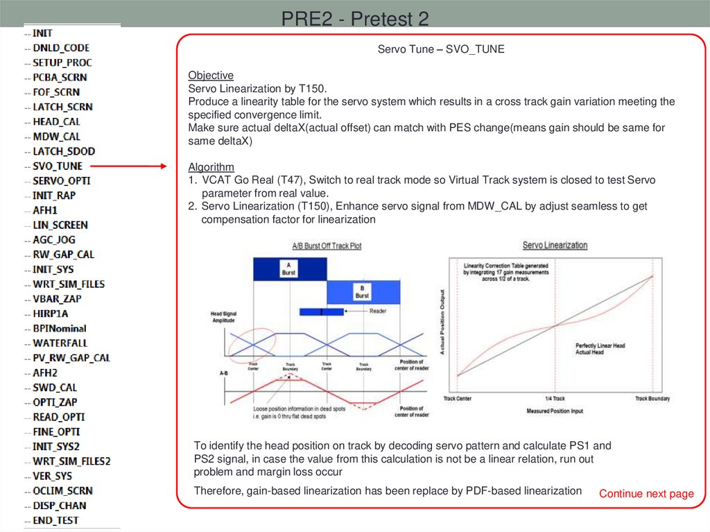
PRE2 - Pretest 2Servo Tune – SVO_TUNE
Objective
Servo Linearization by T150.
Produce a linearity table for the servo system which results in a cross track gain variation meeting the
specified convergence limit.
Make sure actual deltaX(actual offset) can match with PES change(means gain should be same for
same deltaX)
Algorithm
1. VCAT Go Real (T47), Switch to real track mode so Virtual Track system is closed to test Servo
parameter from real value.
2. Servo Linearization (T150), Enhance servo signal from MDW_CAL by adjust seamless to get
compensation factor for linearization
To identify the head position on track by decoding servo pattern and calculate PS1 and
PS2 signal, in case the value from this calculation is not be a linear relation, run out
problem and margin loss occur
Therefore, gain-based linearization has been replace by PDF-based linearization
Continue next page
68.
PRE2 - Pretest 2Servo Tune – SVO_TUNE
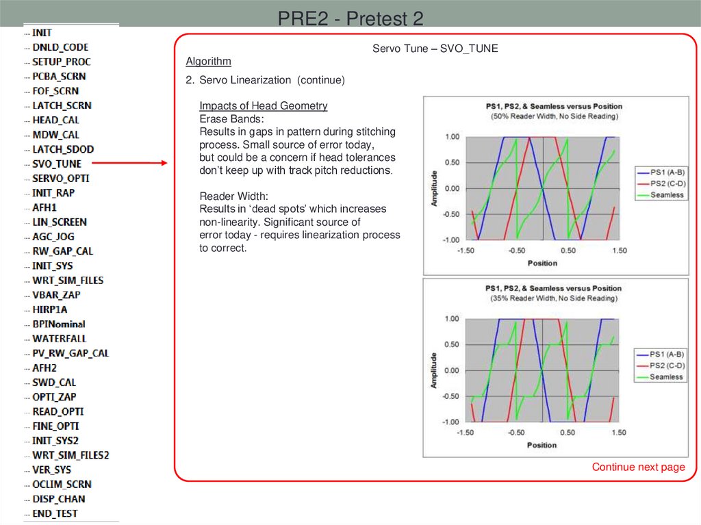
Algorithm
2. Servo Linearization (continue)
Impacts of Head Geometry
Erase Bands:
Results in gaps in pattern during stitching
process. Small source of error today,
but could be a concern if head tolerances
don’t keep up with track pitch reductions.
Reader Width:
Results in ‘dead spots’ which increases
non-linearity. Significant source of
error today - requires linearization process
to correct.
Continue next page
69.
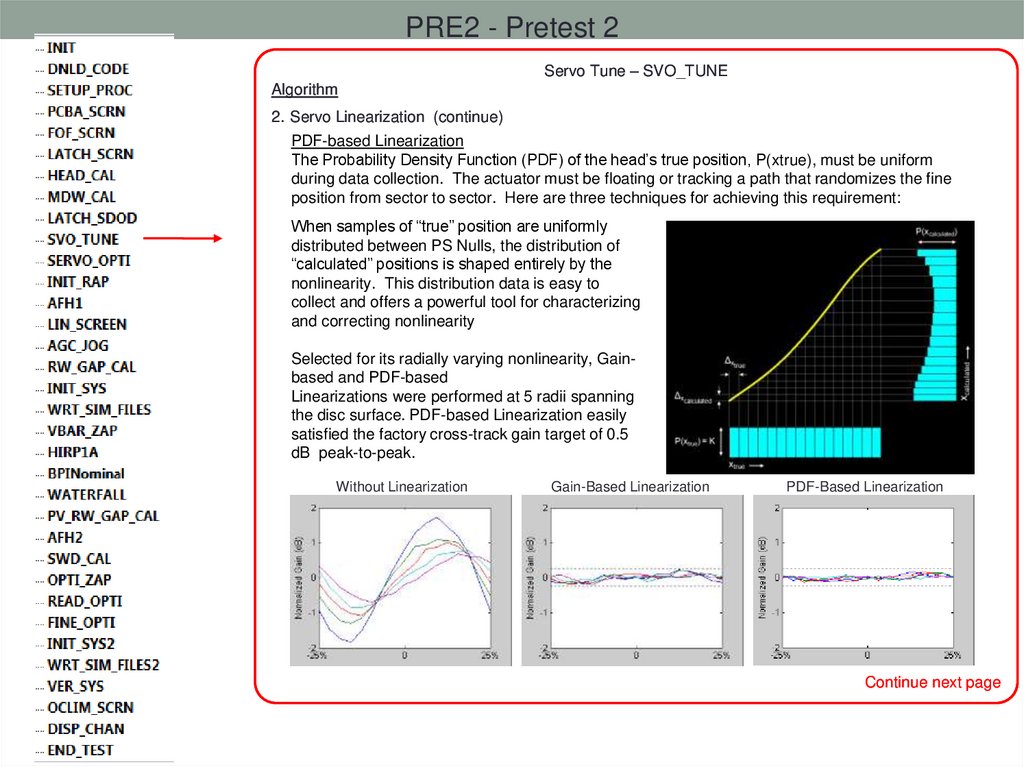
PRE2 - Pretest 2Servo Tune – SVO_TUNE
Algorithm
2. Servo Linearization (continue)
PDF-based Linearization
The Probability Density Function (PDF) of the head’s true position, P(xtrue), must be uniform
during data collection. The actuator must be floating or tracking a path that randomizes the fine
position from sector to sector. Here are three techniques for achieving this requirement:
When samples of “true” position are uniformly
distributed between PS Nulls, the distribution of
“calculated” positions is shaped entirely by the
nonlinearity. This distribution data is easy to
collect and offers a powerful tool for characterizing
and correcting nonlinearity
Selected for its radially varying nonlinearity, Gainbased and PDF-based
Linearizations were performed at 5 radii spanning
the disc surface. PDF-based Linearization easily
satisfied the factory cross-track gain target of 0.5
dB peak-to-peak.
Without Linearization
Gain-Based Linearization
PDF-Based Linearization
Continue next page
70.
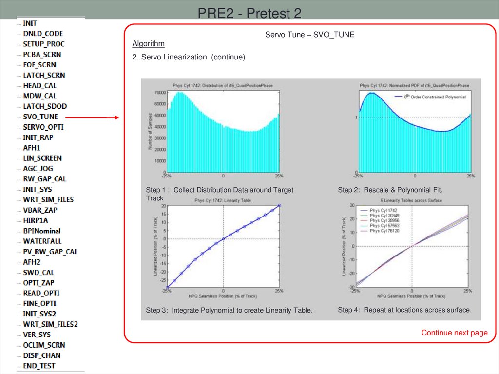
PRE2 - Pretest 2Servo Tune – SVO_TUNE
Algorithm
2. Servo Linearization (continue)
Step 1 : Collect Distribution Data around Target
Track
Step 2: Rescale & Polynomial Fit.
Step 3: Integrate Polynomial to create Linearity Table.
Step 4: Repeat at locations across surface.
Continue next page
71.
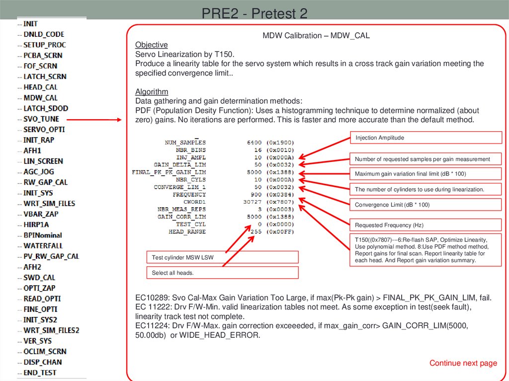
PRE2 - Pretest 2MDW Calibration – MDW_CAL
Objective
Servo Linearization by T150.
Produce a linearity table for the servo system which results in a cross track gain variation meeting the
specified convergence limit..
Algorithm
Data gathering and gain determination methods:
PDF (Population Desity Function): Uses a histogramming technique to determine normalized (about
zero) gains. No iterations are performed. This is faster and more accurate than the default method.
Injection Amplitude
Number of requested samples per gain measurement
Maximum gain variation final limit (dB * 100)
The number of cylinders to use during linearization.
Convergence Limit (dB * 100)
Requested Frequency (Hz)
Test cylinder MSW LSW
T150((0x7807)---6:Re-flash SAP, Optimize Linearity,
Use polynomial method. 8:Use PDF method method,
Report gains for final scan. Report linearity table for
each head. And Report gain variation summary.
Select all heads.
EC10289: Svo Cal-Max Gain Variation Too Large, if max(Pk-Pk gain) > FINAL_PK_PK_GAIN_LIM, fail.
EC 11222: Drv F/W-Min. valid linearization tables not meet. As some exception in test(seek fault),
linearity track test not complete.
EC11224: Drv F/W-Max. gain correction exceeeded, if max_gain_corr> GAIN_CORR_LIM(5000,
50.00db) or WIDE_HEAD_ERROR.
Continue next page
72.
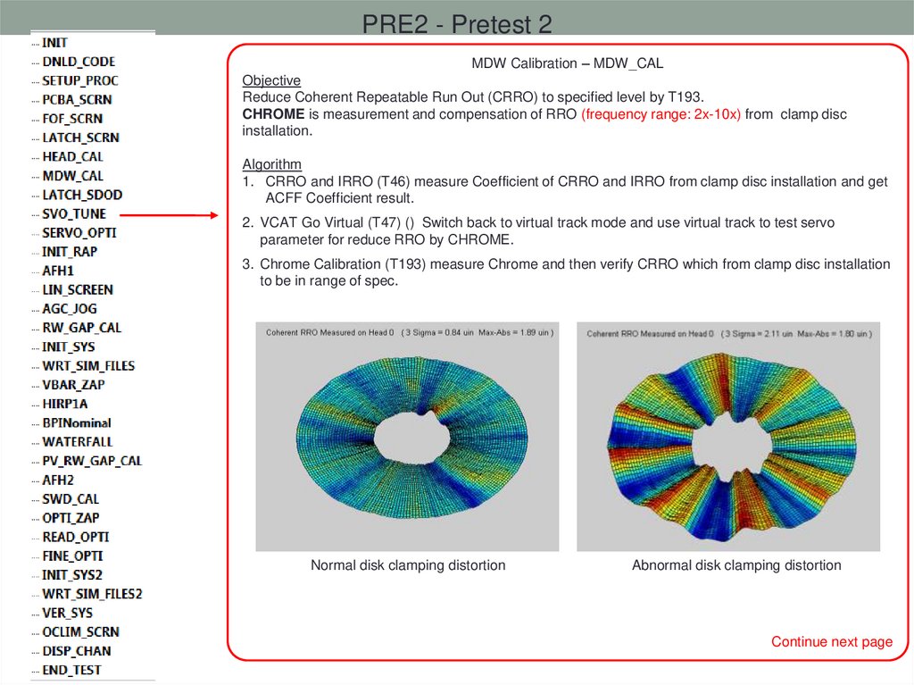
PRE2 - Pretest 2MDW Calibration – MDW_CAL
Objective
Reduce Coherent Repeatable Run Out (CRRO) to specified level by T193.
CHROME is measurement and compensation of RRO (frequency range: 2x-10x) from clamp disc
installation.
Algorithm
1. CRRO and IRRO (T46) measure Coefficient of CRRO and IRRO from clamp disc installation and get
ACFF Coefficient result.
2. VCAT Go Virtual (T47) () Switch back to virtual track mode and use virtual track to test servo
parameter for reduce RRO by CHROME.
3. Chrome Calibration (T193) measure Chrome and then verify CRRO which from clamp disc installation
to be in range of spec.
Normal disk clamping distortion
Abnormal disk clamping distortion
Continue next page
73.
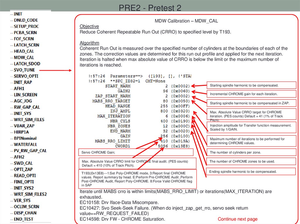
PRE2 - Pretest 2MDW Calibration – MDW_CAL
Objective
Reduce Coherent Repeatable Run Out (CRRO) to specified level by T193.
Algorithm
Coherent Run Out is measured over the specified number of cylinders at the boundaries of each of the
zones. The correction values are determined for this run out profile and applied for the next iteration.
Iteration is halted when max absolute value of CRRO is below the limit or the maximum number of
iterations is reached.
Starting spindle harmonic to be compensated.
Incremental CHROME gain for each iteration.
Starting spindle harmonic to be compensated in ZAP.
Max. Absolute Value CRRO target for CHROME
iteration. (PES counts) Default = 41 (1% of Track
Pitch).
Injection amplitude for Transfer function measurement.
Scaled by 1/GAIN.
Maximum number of iterations to be performed for
determining CHROME values.
Servo CHROME Gain;
The number of cylinders per zone.
Max. Absolute Value CRRO limit for CHROME final audit. (PES counts)
Default = 410 (10% of Track Pitch).
The number of CHROME zones to be used.
T193((0x13E8)---1:Set Poly-CHROME mode, 3:Report final CHROME
values. Report summary by head. E:Perform Pre-CHROME Audit ,Perform
Post-CHROME Audit, Report Poly-CHROME. 8:Force Valid CHROME flag
in SAP
Ending spindle harmonic to be compensated.
Iterate until MABS crro is within limits(MABS_RRO_LIMIT) or iterations(MAX_ITERATION) are
exhausted.
EC10158: Drv Iface-Data Miscompare.
EC10427: Svo Seek-Seek Failure. (When do inject_zap_get_rro, servo seek return
value==RW_REQUEST_FAILED)
EC14598: Drv FW - CHROME Saturation.
Continue next page
74.
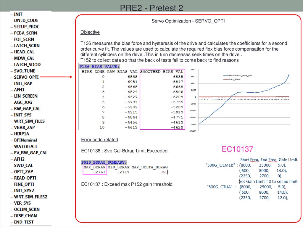
PRE2 - Pretest 2Servo Optimization - SERVO_OPTI
Objective
.
T136 measures the bias force and hysteresis of the drive and calculates the coefficients for a second
order curve fit. The values are used to calculate the required flex bias force compensation for the
different cylinders on the drive .This in turn decreases seek times on the drive .
T152 to collect data so that the back of tests fail to come back to find reasons
Error code related
EC10136 : Svo Cal-Bdrag Limit Exceeded.
EC10137 : Exceed max P152 gain threshold.
EC10137
75.
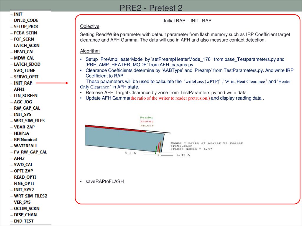
PRE2 - Pretest 2Initial RAP – INIT_RAP
Objective
Setting Read/Write parameter with default parameter from flash memory such as IRP Coefficient target
clearance and AFH Gamma. The data will use in AFH and also measure contact detection.
Algorithm
• Setup PreAmpHeaterMode by ‘setPreampHeaterMode_178’ from base_Testparameters.py and
‘PRE_AMP_HEATER_MODE’ from AFH_params.py
• Clearance Coefficients determine by ‘AABType’ and ‘Preamp’ from TestParameters.py. And write IRP
Coefficient to RAP
These parameters will be used to calculate the ‘writeLoss (wPTP)’ ,’ Write Heat Clearance ’ and ‘Heater
Only Clearance ’ in AFH state.
• Retrieve AFH Target Clearance by zone from TestParamters.py and write data
• Update AFH Gamma(the ratio of the writer to reader protrusion.) and display reading data .
• saveRAPtoFLASH
76.
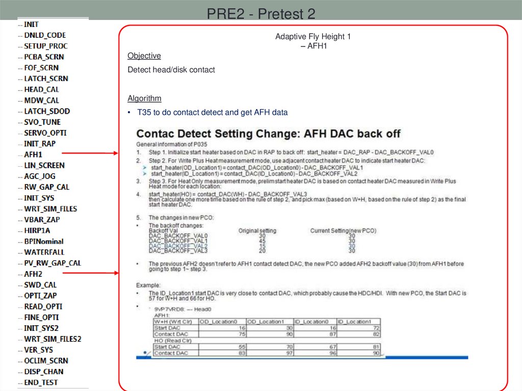
PRE2 - Pretest 2Adaptive Fly Height 1
– AFH1
Objective
Detect head/disk contact
Algorithm
• T35 to do contact detect and get AFH data
77.
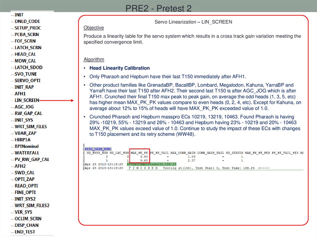
PRE2 - Pretest 2Servo Linearization – LIN_SCREEN
Objective
Produce a linearity table for the servo system which results in a cross track gain variation meeting the
specified convergence limit.
Algorithm
• Head Linearity Calibration
• Only Pharaoh and Hepburn have their last T150 immediately after AFH1.
• Other product families like GrenadaBP, BacallBP, Lombard, Megalodon, Kahuna, YarraBP and
YarraR have their last T150 after AFH2. Their second last T150 is after AGC_JOG which is after
AFH1. Crunched their final T150 max peak to peak gain, on average the odd heads (1, 3, 5, etc)
has higher mean MAX_PK_PK values compare to even heads (0, 2, 4, etc). Except for Kahuna, on
average about 12% to 15% of heads will have MAX_PK_PK exceeded value of 1.0.
• Crunched Pharaoh and Hepburn masspro ECs 10219, 13219, 10463. Found Pharaoh is having
29% -10219, 55% - 13219 and 26% - 10463 and Hepburn having 23% - 10219 and 20% - 10463
MAX_PK_PK values exceed value of 1.0. Continue to study the impact of these ECs with changes
to T150 placement and its retry scheme (WW48).
78.
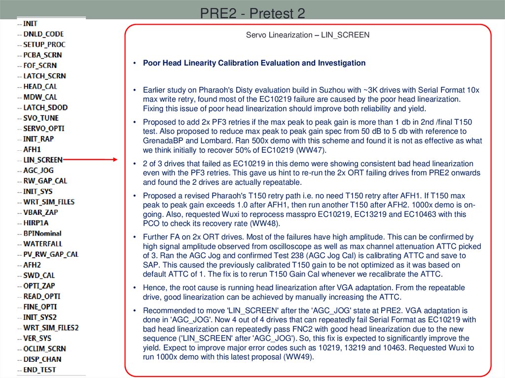
PRE2 - Pretest 2Servo Linearization – LIN_SCREEN
• Poor Head Linearity Calibration Evaluation and Investigation
• Earlier study on Pharaoh's Disty evaluation build in Suzhou with ~3K drives with Serial Format 10x
max write retry, found most of the EC10219 failure are caused by the poor head linearization.
Fixing this issue of poor head linearization should improve both reliability and yield.
• Proposed to add 2x PF3 retries if the max peak to peak gain is more than 1 db in 2nd /final T150
test. Also proposed to reduce max peak to peak gain spec from 50 dB to 5 db with reference to
GrenadaBP and Lombard. Ran 500x demo with this scheme and found it is not as effective as what
we think initially to recover 50% of EC10219 (WW47).
• 2 of 3 drives that failed as EC10219 in this demo were showing consistent bad head linearization
even with the PF3 retries. This gave us hint to re-run the 2x ORT failing drives from PRE2 onwards
and found the 2 drives are actually repeatable.
• Proposed a revised Pharaoh's T150 retry path i.e. no need T150 retry after AFH1. If T150 max
peak to peak gain exceeds 1.0 after AFH1, then run another T150 after AFH2. 1000x demo is ongoing. Also, requested Wuxi to reprocess masspro EC10219, EC13219 and EC10463 with this
PCO to check its recovery rate (WW48).
• Further FA on 2x ORT drives. Most of the failures have high amplitude. This can be confirmed by
high signal amplitude observed from oscilloscope as well as max channel attenuation ATTC picked
of 3. Ran the AGC Jog and confirmed Test 238 (AGC Jog Cal) is calibrating ATTC and save to
SAP. This caused the previously calibrated T150 gain to be not optimized as it was based on
default ATTC of 1. The fix is to rerun T150 Gain Cal whenever we recalibrate the ATTC.
• Hence, the root cause is running head linearization after VGA adaptation. From the repeatable
drive, good linearization can be achieved by manually increasing the ATTC.
• Recommended to move 'LIN_SCREEN' after the 'AGC_JOG' state at PRE2. VGA adaptation is
done in 'AGC_JOG'. Now 4 out of 4 drives that can repeatedly fail Serial Format as EC10219 with
bad head linearization can repeatedly pass FNC2 with good head linearization due to the new
sequence ('LIN_SCREEN' after 'AGC_JOG'). So, this fix is expected to significantly improve the
yield. Expect to improve major error codes such as 10219, 13219 and 10463. Requested Wuxi to
run 1000x demo with this latest proposal (WW49).
79.
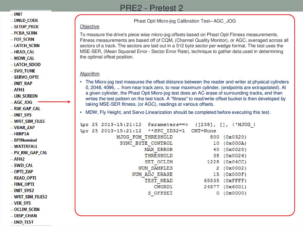
PRE2 - Pretest 2Phast Opti Micro-jog Calibration Test– AGC_JOG
Objective
To measure the drive's piece wise micro-jog offsets based on Phast Opti Fitness measurements.
Fitness measurements are based off of CQM, (Channel Quality Monitor), or AGC, averaged across all
sectors of a track. The sectors are laid out in a 512 byte sector per wedge format. The test uses the
MSE-SER, (Mean Squared Error - Sector Error Rate), technique to gather data used in determining
the optimal offset position.
Algorithm
• The Micro-jog test measures the offset distance between the reader and writer at physical cylinders
0, 2048, 4096, ... from near track zero, to near maximum cylinder, (endpoints are extrapolated). At
a given cylinder, the Phast Opti Micro-jog test does an AC erase of surrounding tracks, and then
writes the test pattern on the test track. A "fitness" to read/write offset bucket is then developed by
taking MSE-SER fitness, (or AGC), readings at various offsets.
• MDW, Fly Height, and Servo Linearization should be completed before executing this test.
80.
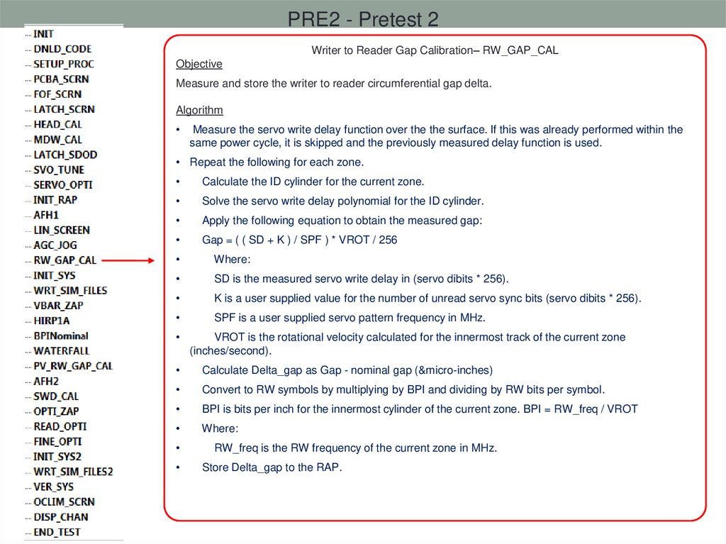
PRE2 - Pretest 2Writer to Reader Gap Calibration– RW_GAP_CAL
Objective
Measure and store the writer to reader circumferential gap delta.
Algorithm
Measure the servo write delay function over the the surface. If this was already performed within the
same power cycle, it is skipped and the previously measured delay function is used.
• Repeat the following for each zone.
Calculate the ID cylinder for the current zone.
Solve the servo write delay polynomial for the ID cylinder.
Apply the following equation to obtain the measured gap:
Gap = ( ( SD + K ) / SPF ) * VROT / 256
Where:
SD is the measured servo write delay in (servo dibits * 256).
K is a user supplied value for the number of unread servo sync bits (servo dibits * 256).
SPF is a user supplied servo pattern frequency in MHz.
VROT is the rotational velocity calculated for the innermost track of the current zone
(inches/second).
Calculate Delta_gap as Gap - nominal gap (µ-inches)
Convert to RW symbols by multiplying by BPI and dividing by RW bits per symbol.
BPI is bits per inch for the innermost cylinder of the current zone. BPI = RW_freq / VROT
Where:
RW_freq is the RW frequency of the current zone in MHz.
Store Delta_gap to the RAP.
81.
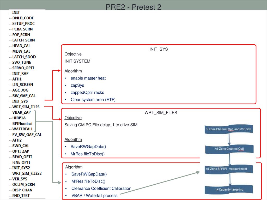
PRE2 - Pretest 2INIT_SYS
Objective
INIT SYSTEM
Algorithm
enable master heat
zapSys
zappedOptiTracks
Clear system area (ETF)
WRT_SIM_FILES
Objective
Saving CM PC File delay_1 to drive SIM
Algorithm
SaveRWGapData()
MrRes.fileToDisc()
Algorithm
SaveRWGapData()
MrRes.fileToDisc()
Clearance Coefficient Calibration
VBAR / Waterfall process
82.
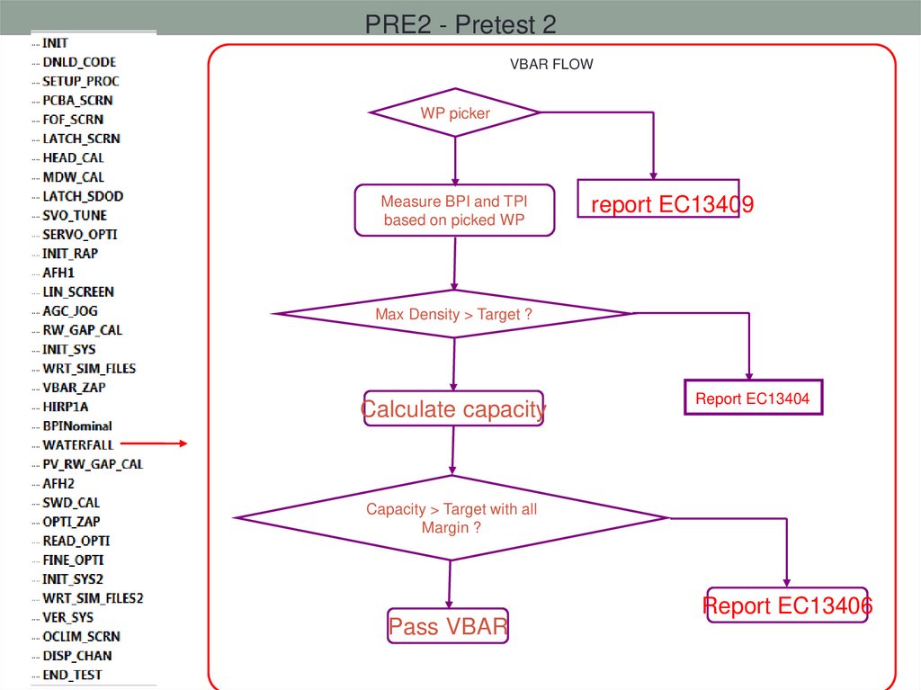
PRE2 - Pretest 2VBAR FLOW
WP picker
Measure BPI and TPI
based on picked WP
report EC13409
Max Density > Target ?
Calculate capacity
Report EC13404
Capacity > Target with all
Margin ?
Pass VBAR
Report EC13406
83.
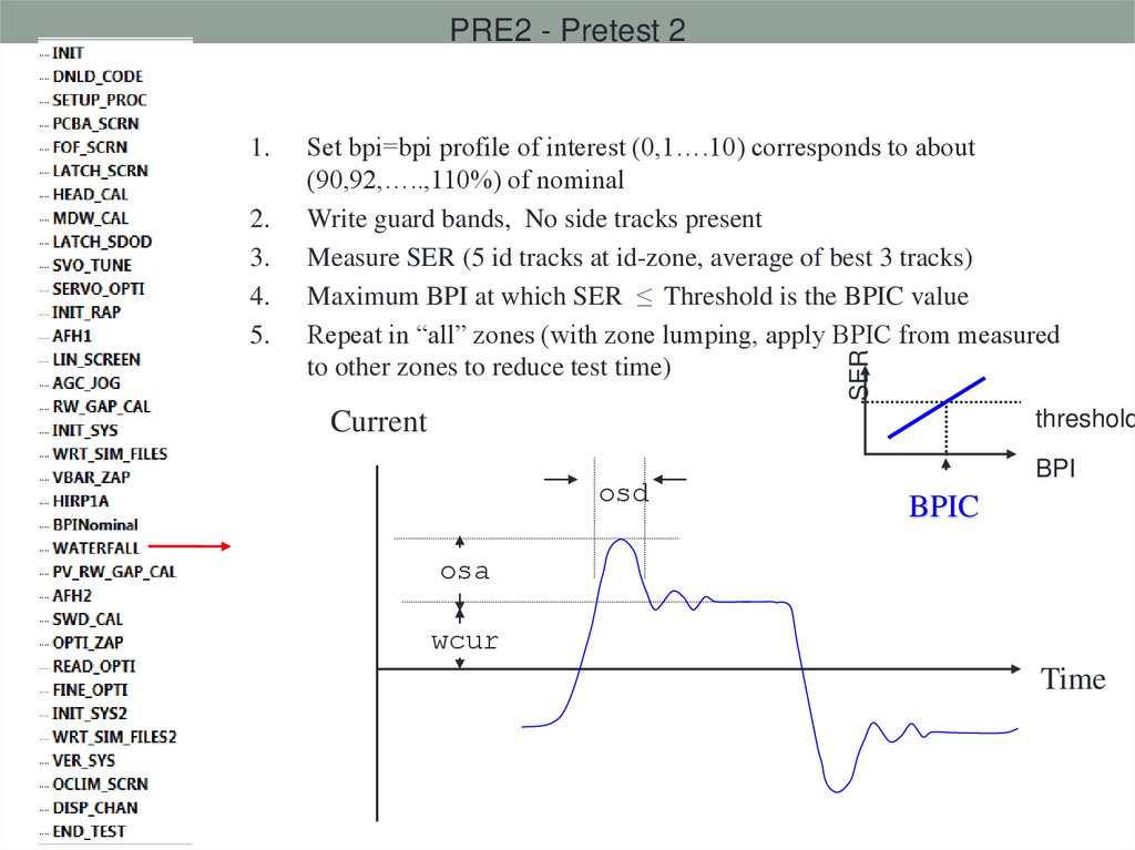
PRE2 - Pretest 22.
3.
4.
5.
Set bpi=bpi profile of interest (0,1….10) corresponds to about
(90,92,…..,110%) of nominal
Write guard bands, No side tracks present
Measure SER (5 id tracks at id-zone, average of best 3 tracks)
Maximum BPI at which SER ≤ Threshold is the BPIC value
Repeat in “all” zones (with zone lumping, apply BPIC from measured
to other zones to reduce test time)
SER
1.
threshold
Current
osd
BPI
BPIC
osa
wcur
Time
84.
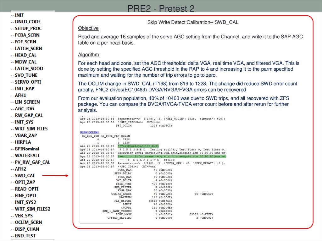
PRE2 - Pretest 2Skip Write Detect Calibration– SWD_CAL
Objective
Read and average 16 samples of the servo AGC setting from the Channel, and write it to the SAP AGC
table on a per head basis.
Algorithm
For each head and zone, set the AGC thresholds: delta VGA, real time VGA, and filtered VGA. This is
done by setting the specified AGC threshold in the RAP to 4 and increasing it to the parm specified
maximum and waiting for the number of trip errors to go to zero.
The OCLIM change in SWD_CAL (T198) from 819 to 1228, The change did reduce SWD error count
greatly, FNC2 drives(EC10463) DVGA/RVGA/FVGA errors can be recovered
From our evaluation population, 40% of 10463 was due to SWD trips, and all recovered with ZFS
package. You can compare the DVGA/RVGA/FVGA error count before and after rerun for further
analysis.
85.
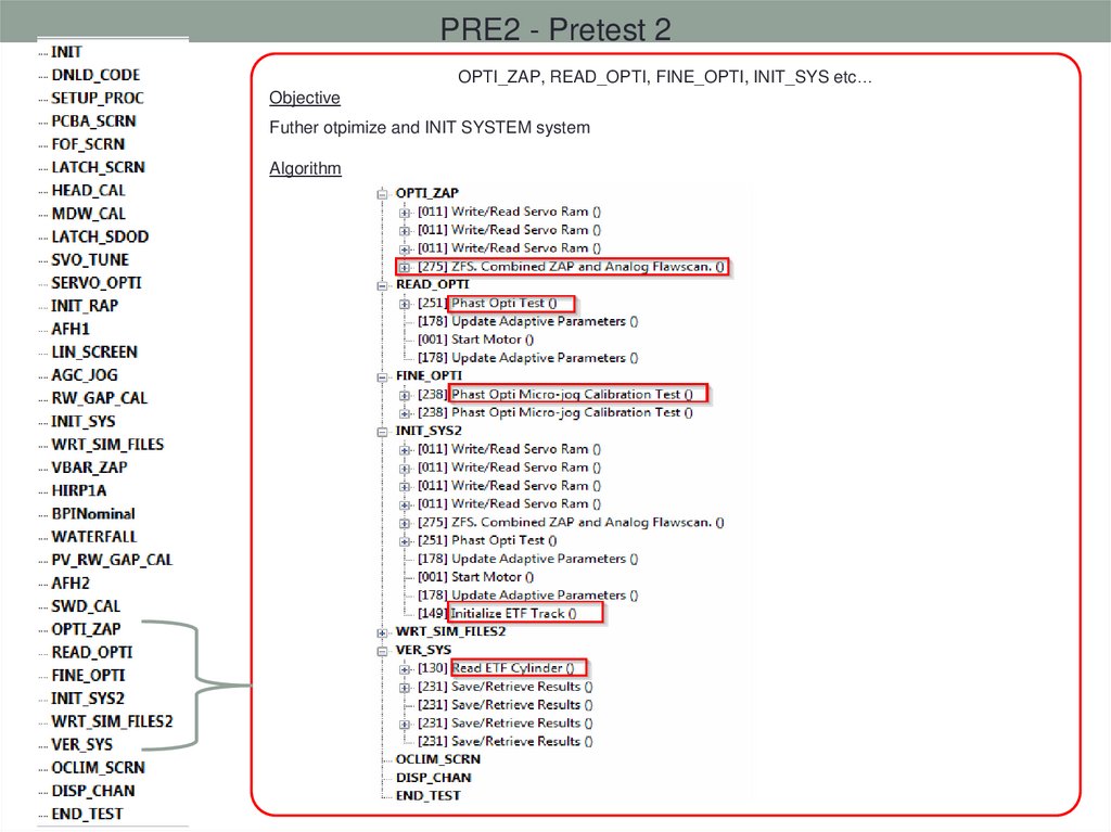
PRE2 - Pretest 2OPTI_ZAP, READ_OPTI, FINE_OPTI, INIT_SYS etc…
Objective
Futher otpimize and INIT SYSTEM system
Algorithm
86.
FNC2 - Functional 2DNLD_CODE2– updateCodeRevisions()
Objective
DNLD_CODE2 is not true download code act, it just print code Rev of RAP, SERVO CODE,
PREAMP_VER etc… of SELFTEST_PACKAGENAME
Algorithm
DNLD_CODE, DNLD_CODEB, DNLD_CODE3 is doing download code act, detail as below:
87.
FNC2 - Functional 2PARTICLE_SWEEP– PARTICLE_SWP2 , 3
Objective
Partcile mitigation test
Algorithm
Doing particle sweep test loop, OEM, disty loop setting is different, Prime and Rework has difference as
well.
88.
FNC2 - Functional 2Analog Flaw Scan– A_FLAWSCAN
Algorithm
Zap collection
Analog Flaw Scan
TA, Servo and
SWD
ScrtachFill
1st Format (DFS)
Servo and SWD
G to P Merge
2ed Format
CRT2
Servo and SWD
89.
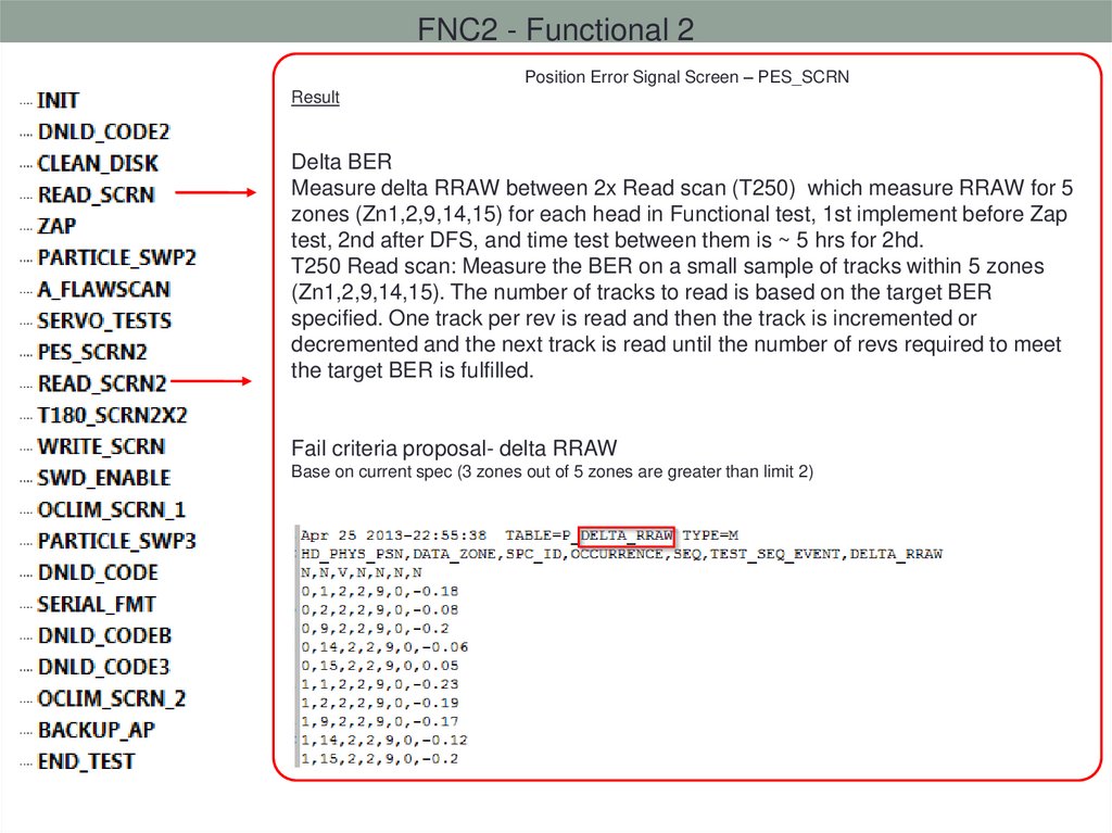
FNC2 - Functional 2Position Error Signal Screen – PES_SCRN
Result
Related formular
1.RAW_RO (Run Out) = SQRT(RRO^2+NRRO^2)
2.NRRO=Sum of ((average NRRO of each sector - average NRRO
of the entire track)^2)
3.RRO=average of N Revolution values
90.
FNC2 - Functional 2Position Error Signal Screen – PES_SCRN
Result
Delta BER
Measure delta RRAW between 2x Read scan (T250) which measure RRAW for 5
zones (Zn1,2,9,14,15) for each head in Functional test, 1st implement before Zap
test, 2nd after DFS, and time test between them is ~ 5 hrs for 2hd.
T250 Read scan: Measure the BER on a small sample of tracks within 5 zones
(Zn1,2,9,14,15). The number of tracks to read is based on the target BER
specified. One track per rev is read and then the track is incremented or
decremented and the next track is read until the number of revs required to meet
the target BER is fulfilled.
Fail criteria proposal- delta RRAW
Base on current spec (3 zones out of 5 zones are greater than limit 2)
91.
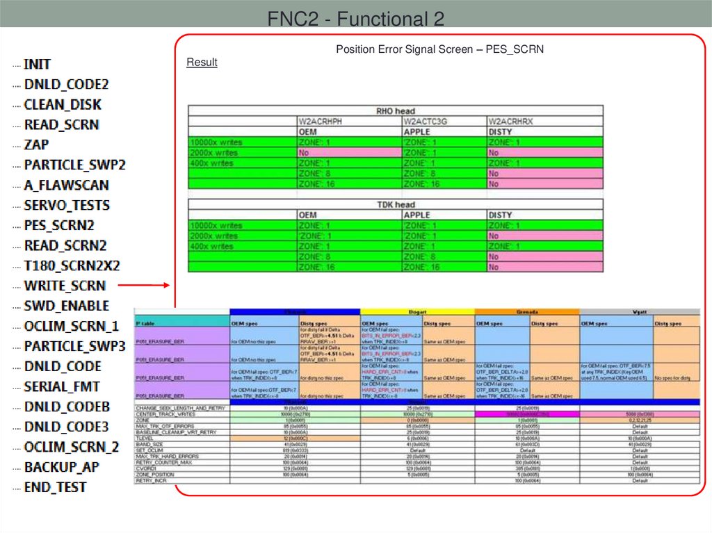
FNC2 - Functional 2Position Error Signal Screen – PES_SCRN
Result
92.
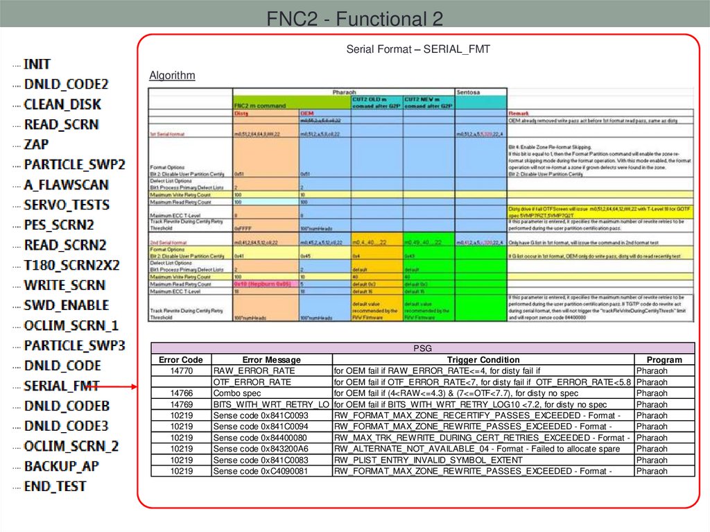
FNC2 - Functional 2Serial Format – SERIAL_FMT
Algorithm
Error Code
14770
14766
14769
10219
10219
10219
10219
10219
10219
PSG
Error Message
Trigger Condition
Program
RAW_ERROR_RATE
for OEM fail if RAW_ERROR_RATE<=4, for disty fail if
Pharaoh
OTF_ERROR_RATE
for OEM fail if OTF_ERROR_RATE<7, for disty fail if OTF_ERROR_RATE<5.8 Pharaoh
Combo spec
for OEM fail if (4<RAW<=4.3) & (7<=OTF<7.7), for disty no spec
Pharaoh
BITS_WITH_WRT_RETRY_LO for OEM fail if BITS_WITH_WRT_RETRY_LOG10 <7.2, for disty no spec
Pharaoh
Sense code 0x841C0093
RW_FORMAT_MAX_ZONE_RECERTIFY_PASSES_EXCEEDED - Format Pharaoh
Sense code 0x841C0094
RW_FORMAT_MAX_ZONE_REWRITE_PASSES_EXCEEDED - Format Pharaoh
Sense code 0x84400080
RW_MAX_TRK_REWRITE_DURING_CERT_RETRIES_EXCEEDED - Format - Pharaoh
Sense code 0x843200A6
RW_ALTERNATE_NOT_AVAILABLE_04 - Format - Failed to allocate spare
Pharaoh
Sense code 0x841C0083
RW_PLIST_ENTRY_INVALID_SYMBOL_EXTENT
Pharaoh
Sense code 0xC4090081
RW_FORMAT_MAX_ZONE_REWRITE_PASSES_EXCEEDED - Format Pharaoh
93. IO Test
• IO test Cmd• Drive
• Serial Port cmd (Internal Diagnose cmd).
• SATA ATA cmd.
• Equipment
• Gemini --- CPC cell, SIC cell
• NP2 --- SIC cell
• IO test Sequence
• FIN2 --- Final Test
• CUT2 --- Customer unique test
• AUD --- Audit test, after print label(CMT state).
•IO test Temperature
• Gemini: (22,20,28)
• NP2: (27,25,33)
94. FIN2 Sequence
FIN2Test Sequence
INIT
DISABLE_UDR2
DISABLE_MC
INTFTTR
DISABLE_MC2
WRITE_XFER
READ_XFER
DO_COMMIT
COMMAND_SET
POWER_MODE
Description
Initialisation:
- Set default cmd timeout, Ramp temperature.
Disable UDR:
Disable Media Cache:
TTR Test:
- Performs 20 power cycles and stores average value to FIN_READY_TIME attribute and P_TTR table. GOTF.
Disable Media Cache:
Zone Based WRITE Transfer Rate Test:
Zone Based READ Transfer Rate Test :
Auto Commit: Turn off for Desaru2D
Command Set:
- Issue ATA command: ExecDeviceDiag, Recalibrate, fluchCache, write/read buffer, seek, seq write/read, rand
write/read, seq write/read ext...
Test Power Mode:
Idle, Idle Immed, Standby, Standby Immed, Sleep
SMART_DFT_LIST
Perform Short Drive Self test :
Write/Read Verify for all Write zone:
Check Smart Defect List:
- Verify smart log A8 and A9 [grown defect list, pending defect list].
CRITICAL_LOG
Check Smart Critical Event Log:
- Verify smart log A1. --- 0x1, 0x2, 0x3, 0x7, 0xB.
VERIFY_SMART
Verify Smart:
- Check SmartReturnStatus: 0xc24f00
RESET_SMART
Reset Smart:
- Initializes SMART statistics data. (1>N1)
RESET_DOS
ENABLE_MC
ENABLE_UDR2
END_TEST
Directed Offline Scan:
Enable Media Cache:
Enable UDR:
Test cleanup
SMART_DST
WR_VERIFY
95. CUT2 Sequence
CUT2Test Sequence
Description
INIT
Initialisation:
- Set default cmd timeout, Ramp temperature.
DISABLE_UDR2
Disable UDR:
DISABLE_MC
Media Cache:
ATTR_VAL
DCM Data Validation:
CUST_CFG
Customer Tests:
- Perform customer tests based on DCM and PIF entries.
AMPS_CHECK
ATA Mode Page Set (AMPS) Check:
- Checks drive Congen configuration state.
WR_VERIFY
Write/Read Verification Test:
Handle Write Read Verify for full write and/or full read removal
READ_WWN
WWN Readback Test:
- Compare WWN ID in drive with attribute WW_SATA_ID in FIS
DEFECT_LIST
Checks Defect List:
- Displays and verify RST List to results file(V4)
- Displays and returns the R-list sector and wedge counters. (N18)
SMART_DFT_LIST
Check Smart Defect List:
- Verify smart log A8 and A9
CRITICAL_LOG
Check Smart Critical Event Log:
- Verify smart log A1. --- 0x1, 0x2, 0x3, 0x7, 0xB.
VERIFY_SMART
Verify Smart:
- Check SmartReturnStatus: 0xc24f00
RESET_SMART
Reset Smart:
RESET_DOS
Directed Offline Scan:
ENABLE_MC
Enable Media Cache:
ENABLE_UDR2
Enable UDR:
SDOD
Spin up/down check:
END_TEST
Test cleanup
>1 fail
96. AUD Sequence
AUDTest Sequence
INIT
DIS_RDWR
DISABLE_UDR2
P_SMTDFT_LIST
P_DEFECT_LIST
AMPS_CHECK
P_VERSMT
P_CRI_LOG
DISCSLIP_AUD
AUDSymBER_WW1
EUP_AUD
AUDSymBER_WW2
RESET_SMART
DIS_G_LIST
FU_WRITE
LDST_SMT
G2P_AUD
SDST_SMT
ZEROCFG_AUD
IOEDC_VER
DEFECT_LIST
S_SMTDFT_LIST
S_CRI_LOG
S_VERSMT
RE_SMT
RE_DOS
E_UDR2
END_TEST
Description
Add write/read performance test for screen weak write.
Verify smart read after write value, to sceen weak write drive.
Disable UDR
Verify P-List and G-List before other test, to ensure this is pass drive.
Verify RST list(V4 log) before other test.
ATA Mode Page Set (AMPS) Check.
Verify Smart.
Check Smart Critical Event Log.
DISC SLIP MEASUREMENT by send diag servo cmd.
Collect drive Ber by send Q cmd 600 times.
EUP Test:
5000 loop random start LBA write, followed by full pack read.
Collect drive Ber by send Q cmd 600 times 2nd time.
Compare hot ber with first time, screen head degrade drive.
Reset Smart:
Verify RST list(V4 log) before other test.
Full Pack Write
Long DST
G2P test + full pack read, only for SBS drive.
Short DST
Write/Read zero pattern at Customer indicate area.
IOEDC verify.
Verify RST list(V4 log) before other test.
Verify P-List and G-List.
Check Smart Critical Event Log.
Verify Smart.
Reset Smart.
Reset Dos table.
Enable UDR2.
Test cleanup
97. SMART
SMART: Self-Monitoring, Analysis, and Reporting Technology feature set• The intent of self-monitoring, analysis, and reporting technology (the SMART feature set) is
to protect user data and minimize the likelihood of unscheduled system downtime that may
be caused by predictable degradation and/or fault of the device. By monitoring and storing
critical performance and calibration parameters, SMART feature set devices attempt to
predict the likelihood of near-term degradation or fault condition. Providing the host system
the knowledge of a negative reliability condition allows the host system to warn the user of
the impending risk of a data loss and to advise the user of appropriate action. Support of
this feature set is indicated in the IDENTIFY DEVICE response.
• SMART Include:
• DST.
• Smart Attribute,
• Smart Log,
• Reset Smart(1>N1).
Clear all smart attributes, DST Log sector – log 0x06, 0x07, Selective Self Test Log sector – 0x09,
Threshold sector, Critical Event Log – 0xA1, Smart Extended Error log – log 0x01, 0x02, 0x03 and 0xAA,
G-List Log 0x08, P-List log 0x09, Health log (Smart Frame) – 0xA2
98. Q and A?
99. CPC and SIC
CPC: Common Processor Card• Gemini cells that contain CPC cards are called CPC cells. They are used for testing
the interface of SATA drives. The cell downloads the CPC firmware prior to the start
of IO testing of the drive.
• Two Cell one Card.
SIC: SATA/SAS Initiator Card
• Gemini cells that contain SATA/SAS initiator cards are called SIC cells. Tests a
drive through the interface with faster transfer rate speeds i.e. 6GB than CPC’s
and $50 cheaper per slot. No more cpc’s are being purchased by the company at
this point in time.
• One Cell one Card
100. UDR2
UDR: Unwritten Data Recovery.• It will recover defective sectors not written with host data. (It usually only effective ~10hrs
after serial format) Return 0 ‘s if read error occurred on unwritten zone.
• Disable UDR2 at start of IO tests, to avoid UDE errors from being hidden.
T>F"LTTCPowerOnHours", 0 will disable UDR2.
• Enable UDR2 after factory IO test.
T>F"LTTCPowerOnHours", A restore congen power on hours.
1>N1 clear life cycle hour.
1>N23 clear UDR2Disable bit.
UDR2 Not support
101. DOS
DOS: Directed Off-line Scan.• It is a feature that breaks the drive up into many zones (not related to adaptive zones). For
each zone, the drive keeps track of how often each zone is written to.
• During idle times, the drive checks the table for zones with values over some trigger
threshold. Threshold values are controlled by the Congen.
Ought To Scan
Needs To Scan
• Trigger threshold is reached, then a Read of the zone is performed followed by a re-Write of
that zone. To clean up the writes previously made in that zone.
• Once the Read/Write is completed, will reset DOS table.
• Clear DOS table after factory IO test.
• 7>m100 / 7> m100,0,1000000
102. MC
MC: Media Cache• It is a feature that to improve 4K drive burst performance. (Host: 512 --- Drve: 4096)
• writing random user data sequentially on the media in order to improve burst random write
performance OR an L2 user data cache, where L1 is a DRAM-based cache as commonly
implemented in HDDs OR a way to prevent costly read-modify-write operations due to
differently-sized host LBAs and disc sectors/units.
• Media Cache Table (MCT):
10000 nodes with circular buffer implementation: Head (write to) and Tail (flush from) This is ~250KB of buffer space
with current node size.
• Media Cache layout:
Media Cache occupies 2-5 GB of space. Cache is divided into segments. (D2: 5G)
• Media Cache Disc Location:
OD – Move LBA 0 from PBA 0 to PBA X where X is the size of the Media Cache in sectors. This can be
accomplished by only touching the interface side.
• Media Cache infor in Identify Device.
word 206 SCTFeaturesEnabled bit 13=MC access via SCT is supported. 1=supported; 0=unsupported
word 159 bit 6, value of 1 indicate MC on and value of 0 indicate MC off
103. Zone Based Transfer Rate Test
• Do a write/read transfer test using Test 598• Compare the first and the last zone throughput with DR specs.
D2 spec: (Zn0>77, Zn23>37.1)
• Compare the RATIO with DR specs and GOTF table. (D2 spec >0.6)
104. ATTR_VAL
Validate DCM attributes:Extract DCM data from Web Service in Gemini, compare with data in drive.
CUST_MODEL_NUM, DRV_MODEL_NUM, USER_LBA_COUNT.
Validate other attributes:
Drive SN prefix
Compare SN prefix in drive to with the list pre-setting in script.
ZGS
Compare ZGS setting in drive with drive attribute “ZERO_G_SENSOR” in FIS.
Buffer Size.
Compare PN[4] with drive attribute "DRAM_PHYS_SIZE“ in FIS.
105. CUST_CFG
Perform customer tests based on DCM and PIF entries.• Customer Attribute Information Descriptors (CAID)
• Customer Content
• Customer Screen
HP Unique Request
Dell PPID
Apple Unique Request
Apple Unique Screen
Common Request
Common Request
106. SMART
DST: Drive self test is an attempt to distinguish bad drives from good drives.• DST sequence:
Smart Attribute Test.
Write Test at system area.
Security Test (HP only).
ATA Error Log test(scan smart log, failed when find error).
Test Around Defects. --- Long Dst
Read Scan at OD 500 MB (2 GB for HP) starting at LBA 0. --- Short Dst
Read Scan entire Drive. --- Long Dst
Extended File Scan Test (if applicable). --- Long Dst
Test Around Defects (read tracks around known defects). --- Short Dst
Buffer DRAM Test.
Random Read Test(read 50 random LBA in user area).
Read Scan at ID minimum 300 MB (1 GB for HP) until 90% of Allocated Time (Congenable). --- Short Dst
Smart Attribute Test.
107. SMART
SMART Attribute:• Data that may be useful in determining the health of a particular disk drive.
• Seagate common attribute.
1-166
Default
Threshold
6
Byte
Value
0Fh
3
1-100
0
03h
Pre-Fail
Warranty
Customer
Specific
No
Start/Stop Count
4
1-100
20
32h
Yes
Retired Sectors Count
5
1-100
36
33h
Yes
Must 0 before ship
Power On Hours
9
1-100
0
32h
No
Must 0 before ship
Drive Power Cycle Count
12
1-100
20
32h
Yes
IOEDC Error
•Reported
Desaru2D
special: 184
1-100
99
32h
No
Attribute Name
#
Range
Raw Error Rate
1
Spin Up Time
Notes
Must 0 before ship
Reported
Uncorrectables
187 Count
1-100
0
• Offset
410:411 Spare
when Last reset
Smart 32h
• Offset
412:413 Pending
Smart
Load/Unload
Count
193 Spare
1-100 Count when
0 last reset32h
Offset
422:423
Number
of
ReadAfterWrite(422)
need
Rewrite
ECC On the Fly Count
195
1-166
0
1Ah
No
Pending-Sparing Count
197
1-100
0
12h
No
Must 0 before ship
Uncorrectable Sectors
Count (Offline Scan)
198
1-100
0
10h
No
Must 0 before ship
No
No
108. SMART
SMART Log:• Enhance smart attribute, lead to improved error detection and reporting capability.
• Common Smart Log
• 0xA1: Critical Event Log. “Type” of critical event indicates what caused an entry to be placed.
Critical Event Log Display Format:
0x06: SMART Self Test Log
0x07: Extended Drive Self-Test Log
0xA8: Grown Defect List
If log entries > 0, fail ec14719
0xA9: Pending Defect List
If log entries > 0, fail ec14718
109. SMART
• List of Critical Event Types(Incomplete)Desaru2D only check type as 0x01, 0x02, 0x03, 0x07, 0x0B in smart A1 log.
Event
(hex)
00
01
02
03
07
08
09
0A
0B
0F
10
11
1B
1C
1D
1E
Description
Recovered write error
IOEDC error detected
SMART threshold exceeded
Pending reallocation attempted, LBA marked as
BBm
Reallocation failure
Write to BBm, successful data scrub (mini-cert), no
reallocation performed
Write to BBm, successful reallocation performed
Write to BBm, wedge reallocation performed
Write to BBm, reallocation failure
Read After Write (RAW) Rewrite
RAW Head Clearance Decreased
RAW Head Clearance Increased
DOS Rewrite
Large Shock event
DST repair rewrite
High fly write (SWD)
LBA field
EC field
Attribute Number 0x0C
that tripped
High Fly write
Count
DER Type
DER Retry
110. Error code
All Fail code,testparam,test table
define….
Code define
Global Variable define
W/R reporting
Test Table define
111. Error codes
•codes.h– …\Shared\source\codes\codes.h
– SF3 uses
– For example, 10632 is ‘ Wt/Rd Err Rate-Min. Err Rate Not Met ‘
• proc_codes.h
– …\Shared\source\codes\ proc_codes.h
– PF3 uses
• rw_sense.h
– …/F1_Dev/source/Include/rw_sense.h
– R/W sense/error reporting information
– F3 uses
112. DBlog
–
–
–
–
Firmware
DIN
Tester
DEX
Binary
FIS
Viewer
DEXRPT
Parametric
Parametric
113. Application
114. Download code F3 -> SF3 con’t
Download code F3 -> SF3 con’t1. Run WinFoF -> Choose Com# -> click Load Device
2. 2.Download PCO from FIS
PCO
115. Download code F3 -> SF3
Download code F3 -> SF33. Connect Drive and power on
4. Goto HS Flash
5. Click Browse to find the corresponding xxx.CFM code
6. Click Download and waiting for Download code finished
116. Download code SF3 -> F3
Download code SF3 -> F31. RunWinFOF
2. Connect Driver and power on
3. Goto HS Flash
4. Choose corresponding TGT & OVL code from PCO
5. Download TGT first, then Download OVL.
6. Switch Power
117. How to Get Corresponding Code
1. Open “C:\var\merlin\cfgs\PCO_Name\scripts\codes.py”2. Search the Drive Part_Number then you can find corresponding code name
3. Goto folder C:\var\merlin\cfgs\PCO_Name\dlfiles unzip the corresponding code
Codes.py
SF3 code
F3 code
118. How to download PCBA code
• Connect driver -> Run Sea Master -> Download -> Dump Flash -> choose 512k or1M(depend on product) -> click Backup Entire Flash -> save xx.bin file to folder
119. How to upload PCBA code
Connect driver -> Run Sea Master -> Download -> Bootstrap-> choose BIN or LOD file
you want to upload -> click Download