






 Инженерная графика
Похожие презентации:
Flight controls System presentation
1.
FLIGHT CONTROLSMENU
System presentation
1/42
2.
We will begin this module by ex
plaining the basic
concept of the “Fl
y By Wire“ syste
m.
FLIGHT CONTROLS
MENU
System presentation
2/42
3.
This has the advantage of saving weig
ht on the aircraft,
However, there ar
e, even greater adva
ntages as the video
clip will demonstrate.
In conventional a
ircraft, the moveme
nt of the control col
umn is transferred a
long cables and pull
eys, until it reaches
the control surface t
o be moved.
In the A320 famil
y however, the cabl
es and pulleys have
been replaced by el
ectrical wires.
FLIGHT CONTROLS
MENU
System presentation
3/42
4.
FLIGHT CONTROLSMENU
System presentation
4/42
5.
FLIGHT CONTROLSMENU
System presentation
5/42
6.
FLIGHT CONTROLCOMPUTERS
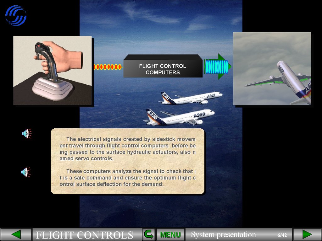
The electrical signals created by sidestick movem
ent travel through flight control computers before be
ing passed to the surface hydraulic actuators, also n
amed servo controls.
These computers analyze the signal to check that i
t is a safe command and ensure the optimum flight c
ontrol surface deflection for the demand.
FLIGHT CONTROLS
MENU
System presentation
6/42
7.
FLIGHT CONTROLCOMPUTERS
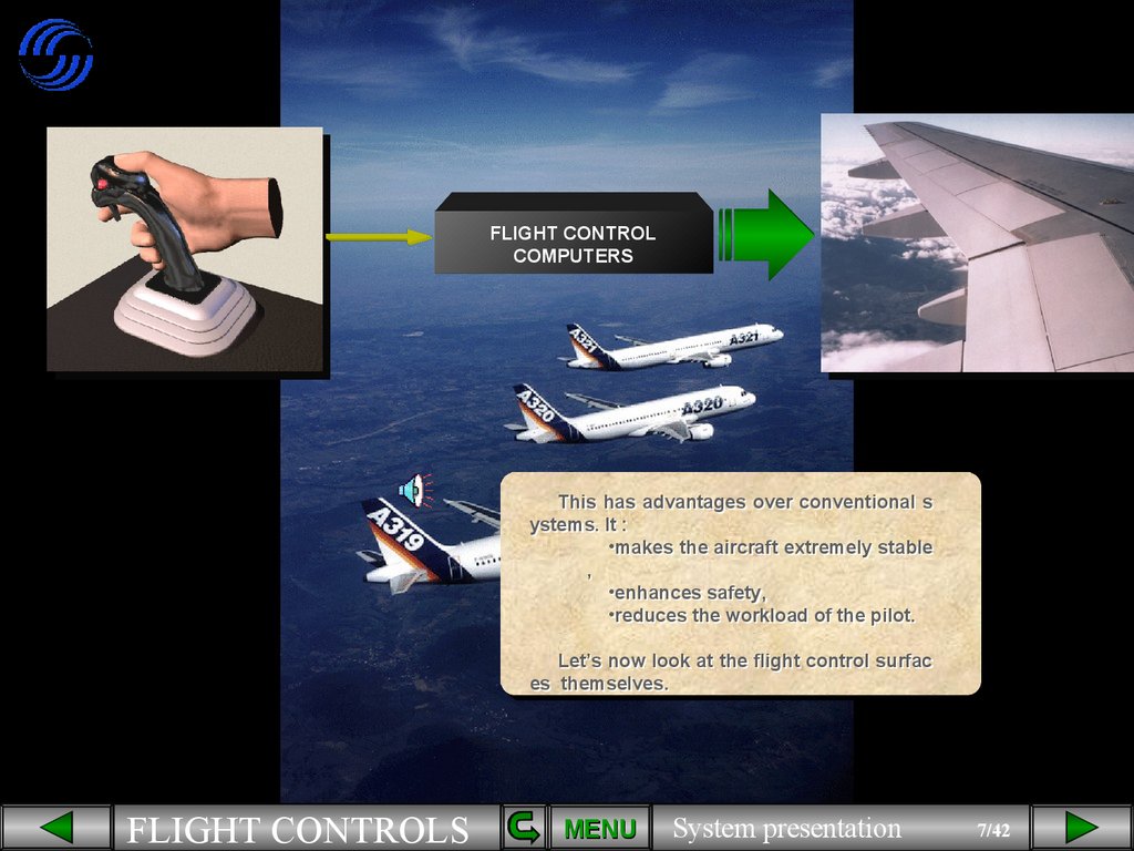
This has advantages over conventional s
ystems. It :
•makes the aircraft extremely stable
,
•enhances safety,
•reduces the workload of the pilot.
Let’s now look at the flight control surfac
es themselves.
FLIGHT CONTROLS
MENU
System presentation
7/42
8.
LAIL
R
AIL
FLIGHT CONTROLS
MENU
System presentation
8/42
9.
RAIL
L
AIL
L
ELEV
R
ELEV
FLIGHT CONTROLS
MENU
System presentation
9/42
10.
RAIL
L
AIL
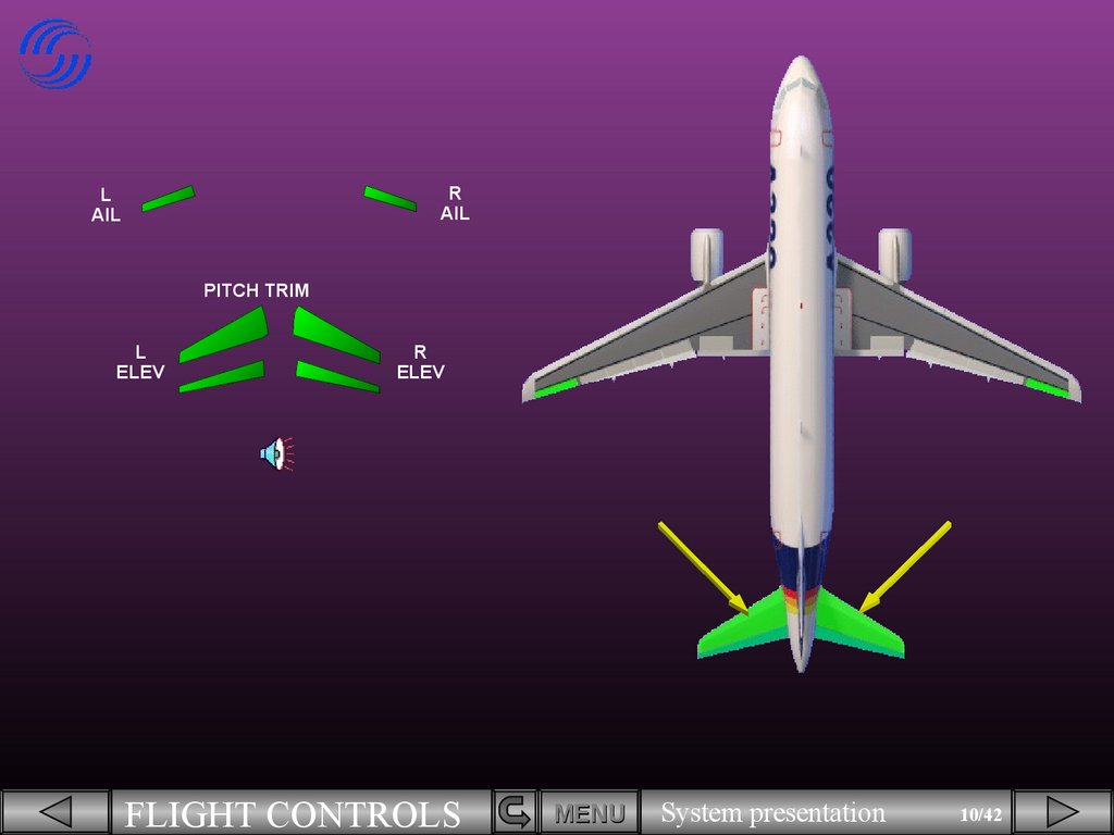
PITCH TRIM
L
ELEV
R
ELEV
FLIGHT CONTROLS
MENU
System presentation
10/42
11.
RAIL
L
AIL
PITCH TRIM
L
ELEV
RUD
R
ELEV
FLIGHT CONTROLS
MENU
System presentation
11/42
12.
SPD BRKL
AIL
R
AIL
PITCH TRIM
L
ELEV
RUD
R
ELEV
The flight control system incorporates:
•Ailerons,
•Elevators,
•A Trimmable Horizontal Stabilizer (THS) for pitch trim,
•A rudder,
•Ground spoilers/Speed brakes.
FLIGHT CONTROLS
MENU
System presentation
12/42
13.
SPD BRKL
AIL
R
AIL
PITCH TRIM
L
ELEV
RUD
R
ELEV
Now let’s introduce the ECAM F/CTL page.
You can see that all the flight control surfaces
we have talked about are displayed. We will now s
ee them in more detail.
FLIGHT CONTROLS
MENU
System presentation
13/42
14.
The movements of both ailerons and both elevators are symbolized by a green index moving in fr
ont of a white scale.
FLIGHT CONTROLS
MENU
System presentation
14/42
15.
The green rudder symbol is used as an index to displaythe movements of the rudder on a white scale.
The rudder trim is indicated by a small blue line below t
he scale.
FLIGHT CONTROLS
MENU
System presentation
15/42
16.
Note that the rudder and the pedal deflections are limited as a function of speed via a rudder
travel limiter.
High
Highspeed
speedposition
position
The high speed position is indicated by sma
ll white ticks on the rudder scale.
FLIGHT CONTROLS
MENU
System presentation
16/42
17.
The PITCH TRIM position is indicated by THS deflection in degrees up or down.
Let’s continue with the spoilers.
FLIGHT CONTROLS
MENU
System presentation
17/42
18.
The spoilers have several functions:
•Speed brakes use the 3 central s
urfaces,
FLIGHT CONTROLS
MENU
System presentation
18/42
19.
•Roll control uses the four outer surfaces,
On the video, look at the left spoilers
as they deploy, then at the right ones as
the wings are leveled .
Click on the video window to start it !
FLIGHT CONTROLS
MENU
System presentation
19/42
20.
•Ground spoilers use all surfaces.On the video, watch as all the spoilers deploy a
t touchdown.
Click on the video window to start it !
FLIGHT CONTROLS
MENU
System presentation
20/42
21.
On the ECAM F/CTL page, the spoiler extended position is indicated by small arrows. This is the speed brake case.
All these control surface indications will be explained in
more detail in the normal and abnormal operation modules.
Now, we will look at the flight control computers.
FLIGHT CONTROLS
MENU
System presentation
21/42
22.
Flight control computersSEC 1
ELAC 1
FAC 1
SEC 2
ELAC 2
FAC 2
SEC 3
The movements of the flight control surfaces are managed by seven computers. These are:
•Two ELevator and Aileron Computers (ELAC),
•Three Spoiler and Elevator Computers (SEC),
•Two Flight Augmentation Computers (FAC).
FLIGHT CONTROLS
MENU
System presentation
22/42
23.
ELAC 1ELAC 2
FCDC 1
FCDC 2
SEC 1
SEC 2
In addition, two Flight Control Data C
oncentrator computers (FCDC) are used
to acquire data from the ELAC and SEC.
Then, they send it to the EIS.
SEC 3
FLIGHT CONTROLS
MENU
System presentation
23/42
24.
ELAC 1However, the data from both FAC is s
ent directly to the EIS.
ELAC 2
FCDC 1
FCDC 2
SEC 1
SEC 2
FAC 1
SEC 3
FLIGHT CONTROLS
FAC 2
MENU
System presentation
24/42
25.
ELAC 1ELAC 2
SEC 1
SEC 2
SEC 3
The status of ELAC and SEC is indicated on the ECAM F/
CTL page. The other computers are not displayed.
These indications will be seen in more detail in the abnor
mal operation module.
Now, we will see the hydraulic aspect.
FLIGHT CONTROLS
MENU
System presentation
25/42
26.
Three independent hydraulic systems are used to power all the flight control surfaces.FLIGHT CONTROLS
MENU
System presentation
26/42
27.
The hydraulic systems which actuate each control surface are indicated on the ECAM F/CTL page b
y the use of G, B and Y.
For example, the rudder is powered by the Gree
n, Blue and Yellow hydraulic systems.
The ECAM F/CTL page is now complete.
FLIGHT CONTROLS
MENU
System presentation
27/42
28.
Pilots control pitch and roll through two side sticks.
FLIGHT CONTROLS
MENU
System presentation
28/42
29.
There are associated side stick priority lights.
Side sticks and priority lights will
be explained in a separate module.
FLIGHT CONTROLS
MENU
System presentation
29/42
30.
Pitch trim wheels are located on the center pedestal.
FLIGHT CONTROLS
MENU
System presentation
30/42
31.
There are two sets of conventional rudder pedals.
FLIGHT CONTROLS
MENU
System presentation
31/42
32.
A RUD TRIM panel is located on the pedestal.
FLIGHT CONTROLS
MENU
System presentation
32/42
33.
A speed brake lever is located on the left side of the pedestal.
FLIGHT CONTROLS
MENU
System presentation
33/42
34.
In addition, there are two panels, located on the overhead panel to control the flight cont
rol computers .
Now, we will introduce the lift augmentatio
n devices.
FLIGHT CONTROLS
MENU
System presentation
34/42
35.
There are 5 slats on each leading edge ...
FLIGHT CONTROLS
MENU
System presentation
35/42
36.
and 2 flaps on each trailing edge.
FLIGHT CONTROLS
MENU
System presentation
36/42
37.
SFCC 1SFCC 2
The slats and flaps are hydraulically actuated like
all the other surfaces. They are electrically controlled
via two Slat Flap Control Computers (SFCC).
FLIGHT CONTROLS
MENU
System presentation
37/42
38.
SFCC 1SLAT CHANNEL
FLAP CHANNEL
SFCC 2
SLAT CHANNEL
FLAP CHANNEL
Each SFCC has two channels, one for the flaps an
d one for the slats.
Each channel can drive its associated surfaces.
FLIGHT CONTROLS
MENU
System presentation
38/42
39.
The flap lever, located on the right side of the pedestal, operates the slats a
nd flaps.
The flap lever has the following posit
ions:
0, 1, 2, 3 and FULL.
FLIGHT CONTROLS
MENU
System presentation
39/42
40.
The flaps and slats information is shown on the E/WD.The flap and slat positions are indicated by white dots. H
ere, the surfaces are extended to position 1+F.
FLIGHT CONTROLS
MENU
System presentation
40/42
41.
This is Flap 0 indication. Notice there is no labeling with this setting.
FLIGHT CONTROLS
MENU
System presentation
41/42
42.
The slats and flaps are fitted with protection functions.
In particular, Surface asymmetry betw
een left and right wing, Surface attachme
nt failure, Overspeed or uncommanded m
ovement are detected.
All these protections will be seen in d
etail in the abnormal operation modules.
Module completed
FLIGHT CONTROLS
MENU
System presentation
42/42
NEXT
43.
LISTLIST OF
OF SUBJECTS
FLIGHT BY WIRE
FLIGHT CONTROL SURFACES
ECAM PAGES
COMPUTERS
HYDRAULIC
CONTROLS
SLATS and FLAPS
AUDIO
GLOSSARY
RETURN
FLIGHT CONTROLS
FCOM
EXIT
MENU
System presentation
43/42