


Magneto Ignition Systems")


 Battery-and-Points Ignition Systems")


 Физика
Похожие презентации:


Internal сombustion engine. Ignition systems
1.
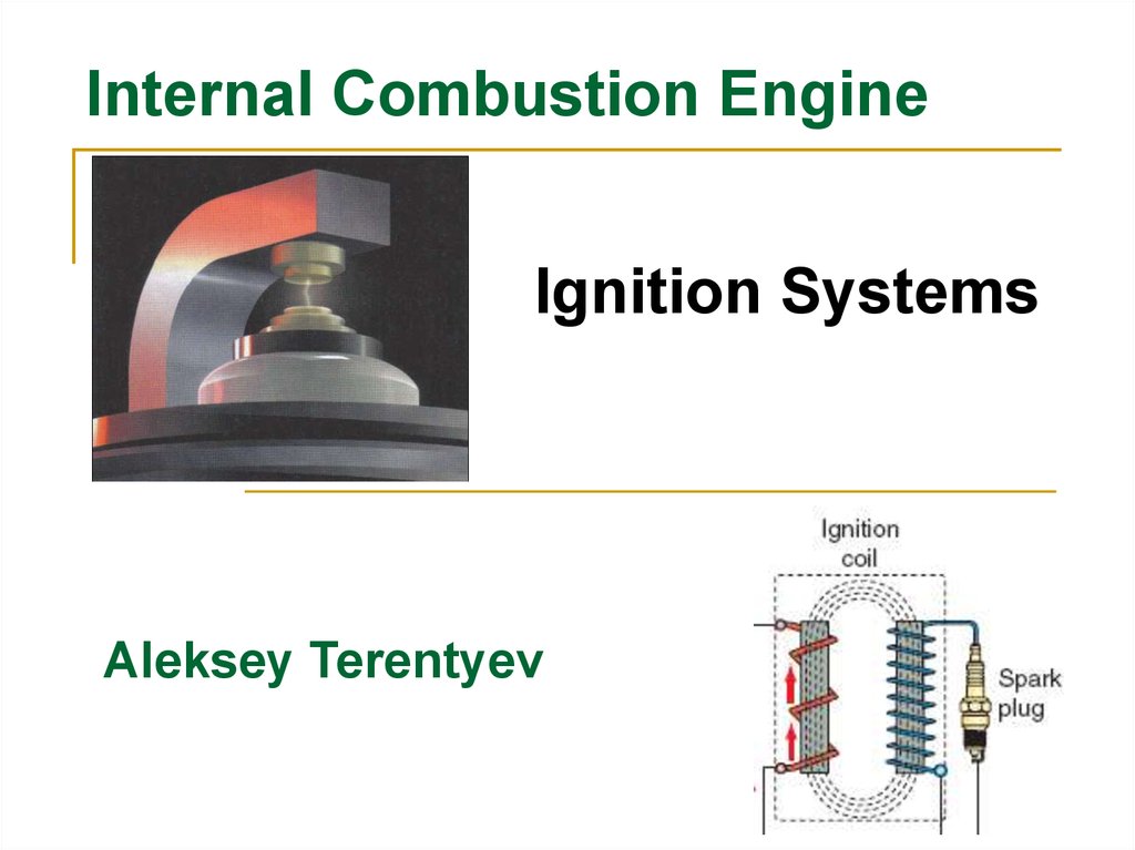
Internal Сombustion EngineIgnition Systems
Aleksey Terentyev
2. INTRODUCTION
Do you remember the stagesof operation in a two-stroke and a
four-stroke engine?
In each cylinder of the engine,
the piston rises during the
compression stage to compress the
air–fuel mixture in the combustion
chamber. Just before the piston
reaches the top-dead center (TDC),
a spark plug fires in the cylinder
and ignites the compressed air–fuel
mixture. The ignition of the air–fuel
mixture forces the piston down in
the cylinder, producing the power
stage.
The power produced by the
ignition of the air–fuel mixture turns
the crankshaft, which in turn keeps
the piston moving and the engine
running.
2
3.
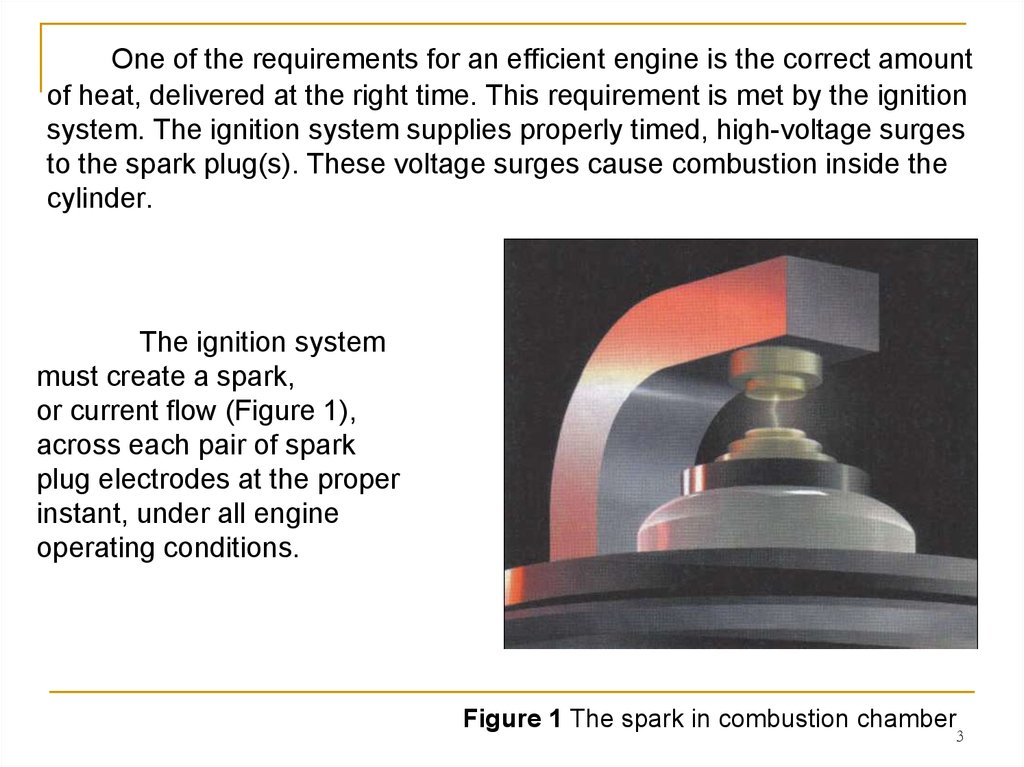
One of the requirements for an efficient engine is the correct amountof heat, delivered at the right time. This requirement is met by the ignition
system. The ignition system supplies properly timed, high-voltage surges
to the spark plug(s). These voltage surges cause combustion inside the
cylinder.
The ignition system
must create a spark,
or current flow (Figure 1),
across each pair of spark
plug electrodes at the proper
instant, under all engine
operating conditions.
Figure 1 The spark in combustion chamber
3
4. POWER EQUIPMENT ENGINE IGNITION SYSTEMS
The sole purpose of an ignitionsystem is to provide a spark that will
ignite the air–fuel mixture in the
combustion chamber. The spark
must be timed to occur at a precise
point relative to the position of the
piston as it reaches TDC on the
engine’s compression stroke. The
difference between various ignition
systems lies in how the spark is
activated. In some of today’s larger
power equipment engines, ignition
systems are used in unison with
electronic fuel injection systems.
4
5. Three main functions of the ignition system
For each cylinder in an engine, the ignition systemhas the following three main functions:
1. It must generate an electrical spark that has
enough heat to ignite the air–fuel mixture in the
combustion chamber;
2. It must maintain that spark long enough to
allow for the combustion of all the air and fuel in the
cylinder;
3. It must deliver a spark so that combustion can
begin at the right time during each compression stroke
of the piston.
5
6.
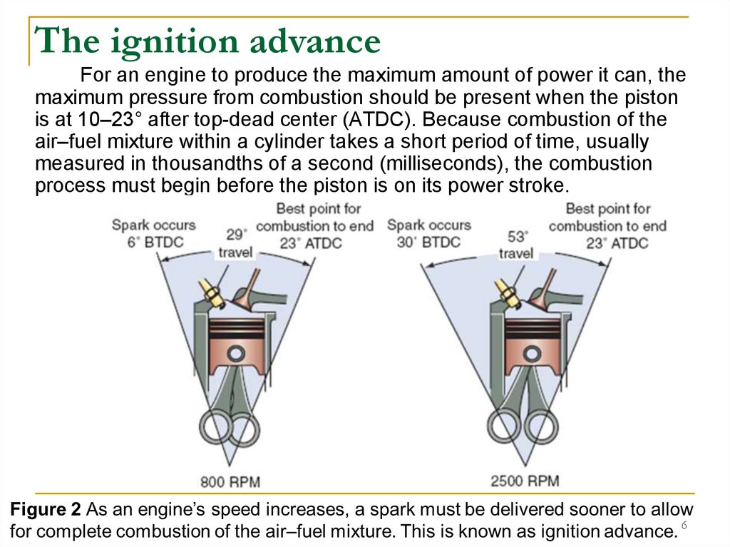
The ignition advanceFor an engine to produce the maximum amount of power it can, the
maximum pressure from combustion should be present when the piston
is at 10–23° after top-dead center (ATDC). Because combustion of the
air–fuel mixture within a cylinder takes a short period of time, usually
measured in thousandths of a second (milliseconds), the combustion
process must begin before the piston is on its power stroke.
6
7.
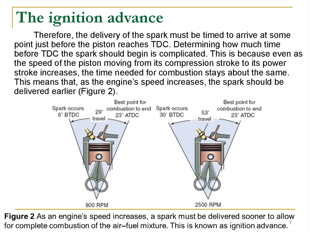
The ignition advanceTherefore, the delivery of the spark must be timed to arrive at some
point just before the piston reaches TDC. Determining how much time
before TDC the spark should begin is complicated. This is because even as
the speed of the piston moving from its compression stroke to its power
stroke increases, the time needed for combustion stays about the same.
This means that, as the engine’s speed increases, the spark should be
delivered earlier (Figure 2).
7
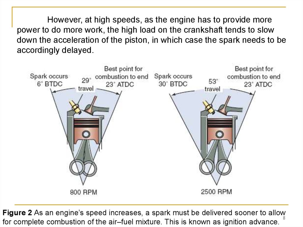
8.
However, at high speeds, as the engine has to provide morepower to do more work, the high load on the crankshaft tends to slow
down the acceleration of the piston, in which case the spark needs to be
accordingly delayed.
Figure 2 As an engine’s speed increases, a spark must be delivered sooner to allow
8
for complete combustion of the air–fuel mixture. This is known as ignition advance.
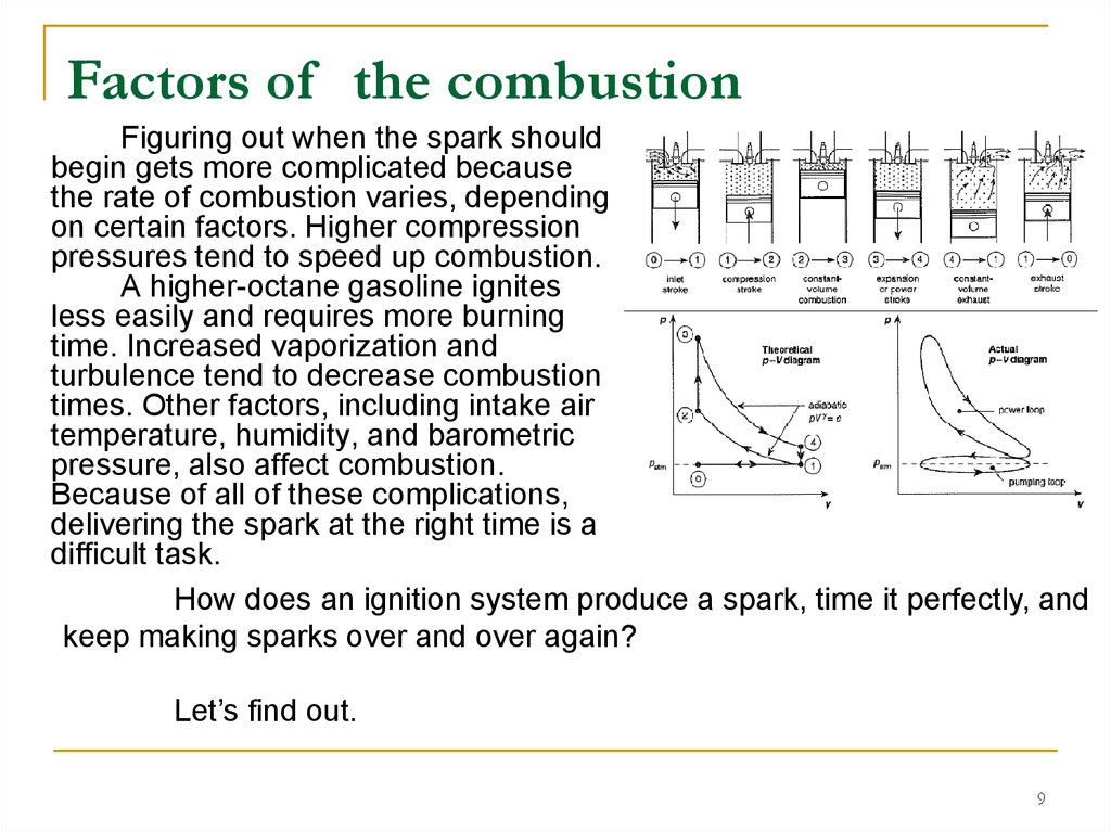
9.
Factors of the combustionFiguring out when the spark should
begin gets more complicated because
the rate of combustion varies, depending
on certain factors. Higher compression
pressures tend to speed up combustion.
A higher-octane gasoline ignites
less easily and requires more burning
time. Increased vaporization and
turbulence tend to decrease combustion
times. Other factors, including intake air
temperature, humidity, and barometric
pressure, also affect combustion.
Because of all of these complications,
delivering the spark at the right time is a
difficult task.
How does an ignition system produce a spark, time it perfectly, and
keep making sparks over and over again?
Let’s find out.
9
10. Ignition Timing
Ignition timing refers to the precise time spark occurs. It’sspecified by referring to the position of a manufacturer-determined piston
(generally the No. 1 piston on the crankshaft in multicylinder engines) in
relation to crankshaft rotation. Ignition timing reference marks are
sometimes located on the engine’s crankshaft flywheel/rotor to indicate
the position of the piston.
Power equipment engine manufacturers specify initial or base
ignition timing. Some engines don’t require such markings because the
ignition systems are fixed in one position and are not adjustable.
Figure 2а Marks on crankshaft pulley and crankshaft sprocket.
10
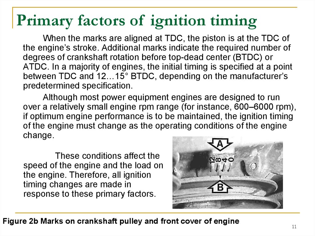
11.
Primary factors of ignition timingWhen the marks are aligned at TDC, the piston is at the TDC of
the engine’s stroke. Additional marks indicate the required number of
degrees of crankshaft rotation before top-dead center (BTDC) or
ATDC. In a majority of engines, the initial timing is specified at a point
between TDC and 12…15° BTDC, depending on the manufacturer’s
predetermined specification.
Although most power equipment engines are designed to run
over a relatively small engine rpm range (for instance, 600–6000 rpm),
if optimum engine performance is to be maintained, the ignition timing
of the engine must change as the operating conditions of the engine
change.
These conditions affect the
speed of the engine and the load on
the engine. Therefore, all ignition
timing changes are made in
response to these primary factors.
Figure 2b Marks on crankshaft pulley and front cover of engine
11
12. Ignition Timing Advance
Power equipment engines generally run at relatively stable enginespeeds, and so ignition advance isn’t required. But in some engines,
speed varies a lot and ignition timing needs to be varied accordingly. In
such cases, it’s necessary to advance or retard ignition in some engines.
Two methods are used in power equipment engines to advance ignition
(Figure 3).
Figure 3 The centrifugal advance mechanisms
12
13. Ignition Timing Advance
Ignition systems in older power equipment engines that requireignition timing advance are equipped with centrifugal advance
mechanisms, which advance or retard ignition timing in response to
engine speed. Centrifugal advance uses a set of pivoted weights and
springs connected to a shaft with the point cam (crankshaft or camshaft)
attached to it.
When engine speed
increases, the weights move
outward, shifting the plate
where the triggering device
is mounted.
This shifting of the plate
causes the triggering device
to receive its signal earlier,
causing an advance in the
ignition timing.
Figure 3 The centrifugal advance mechanisms
13
14. Electronic advance systems
Most all modern day power equipment engines that require advanceuse an electronic advance system to control the ignition. Electronic advance
systems require no adjustment, have no mechanical parts, and therefore
don’t wear out.
The design eliminates
the need for maintenance.
Electronic advance systems
use multiple sensors to
determine the correct timing
advancement for any given
condition. They offer a greater
variety of timing choices for
different engine running
conditions instead of basically
only two, as is case with
centrifugal advance systems.
Figure 3a The electronic advance system
14
15. Engine rpm and Turbulence
At higher rpm, the crankshaft turns through more degrees in agiven period of time. If combustion is to be completed by a particular
number of degrees ATDC, ignition timing must occur sooner—or be
advanced—by the use of a mechanical or electrical advancer. The
advancer is generally attached on the crankshaft.
Another complication that arises at high rpm is the turbulence
(swirling) of the air–fuel mixture, which increases with rpm. This
causes the mixture inside the cylinder to turn faster. Increased
turbulence requires that ignition must occur slightly later—or be
slightly retarded—by the use of the advancer.
These two factors—high rpm and increased turbulence—must
be balanced for optimum engine performance. Therefore, although
ignition timing must be advanced as engine speed increases, the
amount of advance must be decreased to compensate for the
increased turbulence.
15
16. Engine Load
The load on an engine is related to the work it must do. Forexample, cutting deep grass or pulling extra weight increases
engine load. At higher loads, there is greater resistance on the
crankshaft; therefore, the piston has a harder time moving through
their strokes.
Under light loads and with the throttle partially open, a high
vacuum exists in the intake manifold. The amount of air–fuel mixture
drawn into the manifold and cylinders is small. On compression, this
thin mixture produces less combustion pressure, and combustion
time is increased. To complete combustion by the desired degrees
ATDC, ignition timing must be advanced.
Under heavy loads, when the throttle is open fully, a larger
mass of air–fuel mixture is drawn in, and the vacuum in the manifold
is low. High combustion pressure and rapid burning result. In such
cases, ignition timing must be retarded to prevent completion of
burning before the crankshaft has reached the desired degrees
ATDC.
16
17. Firing Order in Multi-Cylinder Engines
Up to this point, we’ve focused primarily on ignition timing as it relates to anyone cylinder. However, the function of an ignition system extends beyond timing
the spark in a single cylinder. In multi-cylinder engines, it must perform this task for
each cylinder of the engine in a specific sequence.
In the case of a multi-cylinder four-stroke engine, each cylinder of the engine
must produce power once in every 720° of crankshaft rotation. Each cylinder must
have a power stroke at its own appropriate time. To make this possible, the
pistons and connecting rods are arranged in a precise fashion called the engine’s
firing order.
The firing order is arranged to reduce rocking and imbalance problems.
Because the potential for this rocking depends on the design and construction of
the engine, the firing order varies from engine to engine. Engine manufacturers
simplify cylinder identification by numbering each cylinder. Regardless of the firing
order used, the No. 1 cylinder always starts the firing, with the rest of the cylinders
following in a fixed sequence.
The ignition system must be able to “monitor” the rotation of the crankshaft
and the relative position of each piston to determine which piston is on its
compression stroke. It must also be able to deliver a high-voltage surge to each
cylinder at the proper time during its compression stroke. How the ignition system
does these things depends on the design of the system.
17
18. BASIC IGNITION SYSTEM COMPONENTS
Figure 4 shows asimplified drawing of a basic
ignition system. The main
components of the system
are the following:
■ Power source
■ Ignition switch
■ Ignition coil
■ Spark plug
■ Triggering switch
■ Stop switch
All ignition systems
contain these components.
The difference is how the
components function.
Figure 4 The basic components of an ignition system.
18
19. Power Sources
In power equipment engineignition systems, there are just
two power source options. These
power sources are the battery
[for direct current (DC)] or the AC
generator [for alternating current
(AC)].
In a battery ignition system,
a battery is connected to the
ignition coil. A triggering switch
device is used to alternately turn
the DC voltage on and off for its
operation.
AC generator power
sources are far more common
than battery systems for power
equipment engines, and in most
cases, they’re designed to be run
without a battery. The ACpowered ignition system uses
the principles of magnetism to
produce a voltage.
Figure 4 The basic components of an ignition system.
19
20. Power Sources
Remember that when aconductor wire is moved
through a magnetic field, a
voltage is induced in the
conductor. It’s also true that
if a magnet is moved near a
conductor, a voltage is
induced in the conductor. If
this conductor wire is
connected to a complete
circuit, current will flow in the
circuit.
In an AC ignition
system, permanent magnets
are installed in the engine’s
flywheel/rotor. As the
flywheel/rotor turns, the
moving magnets cause a
voltage to be induced in the
ignition coil.
Figure 4 The basic components of an ignition system.
20
21. Ignition Switch
The ignition switchallows the power source
to provide electrical
power to the ignition
system. It’s generally a
key-type switch that also
powers all components
that use a power source,
such as lights and
accessories.
Figure 4 The basic components of an ignition system.
21
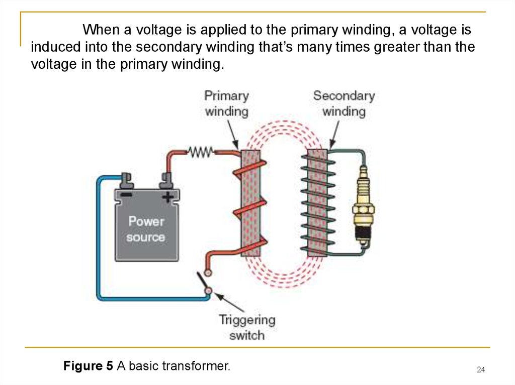
22. Ignition Coil
An ignition coil is essentially a transformer that consists of two wirewindings wound around an iron core (Figure 5). The first winding is called
the primary winding, and the second winding is called the secondary
winding. The secondary winding has many more turns of wire than the
primary winding.
Figure 5 A basic transformer.
22
23. Ignition Coil
In an ignition coil, one end of the coil’s primary winding is alwaysconnected to a powersource. Depending on the type of ignition system, the
power source may be a battery (providing DC (direct current)) or a
flywheel/rotor with a permanent magnet (providing AC (alternating current)).
Either type of power source can be used to apply a voltage to the primary
winding of the coil.
Figure 5 A basic transformer.
23
24.
When a voltage is applied to the primary winding, a voltage isinduced into the secondary winding that’s many times greater than the
voltage in the primary winding.
Figure 5 A basic transformer.
24
25. 20,000–60,000 volts
When current passes through the primary winding of the coil, amagnetic field is created around the iron core. As the magnetic field
expands, the magnetic lines of flux cut through the wires of the secondary
winding and induce a voltage in the secondary winding.
If the current in the
primary winding is switched off,
a voltage is again induced into
the secondary winding by the
magnetic lines of flux, which
again cut through the
secondary winding. The
direction of current induced into
the secondary winding is
reversed each time the current
in the primary is turned on and
off. This is because the
magnetic lines of force around
the iron core cut through the
secondary winding in opposite
directions as the magnetic field
expands and collapses.
Figure 5 A basic transformer.
25
26. 20,000–60,000 volts
Because thesecondary winding of the
coil has many more wire
coils than the primary, the
voltage produced in the
secondary winding is
much higher than the
original voltage applied to
the primary winding. In a
typical power equipment
engine ignition system,
the power source supplies
about 12 volts to the
primary winding of the
ignition coil. From this 12volt input, the ignition coil
produces 20,000–60,000
volts or even more at the
secondary coil.
Figure 5 A basic transformer.
26
27. Different Ignition systems
The secondary winding of the coil is always connected to thespark plug through the spark plug wire. Because the spark plug wire
needs to carry the high voltage and prevent it from arcing to ground,
it’s heavily insulated.
When the magnetic field in
the ignition coil expands or
collapses (coils are designed to
do one or the other), the high
voltage in the secondary is
applied to the spark plug and
causes a spark to jump across
the spark plug gap. The spark
ignites the air–fuel mixture,
enabling the power equipment
engine to run.
Figure 5 A basic transformer.
27
28. Different Ignition systems
It’s important to remember that the high voltage in the secondarywinding of the coil is produced each time the primary current is turned
on or off.
In a collapsing-field ignition
system, the high voltage from
the secondary winding is used
when the current to the primary
winding is switched off.
In a rising-field ignition
system, the high voltage from
the secondary winding is used
when the current to the primary
winding is switched on. This
means that all ignition systems
need some type of a device that
will keep turning the current from
the power source on and off.
Figure 5 A basic transformer.
28
29. Spark Plug
The spark plug provides the crucialair gap across which the high voltage
from the secondary coil causes an arc or
spark.
The main parts of a spark plug are
- a steel shell;
- a ceramic core or insulator, which
acts as a heat conductor; and
- a pair of electrodes, one insulated
in the core and the other grounded on
the shell.
The shell holds the ceramic core
and electrodes in a gastight assembly
and has threads for plug installation in
the engine (Figure 6).
Figure 6 The parts of a typical spark plug.
29
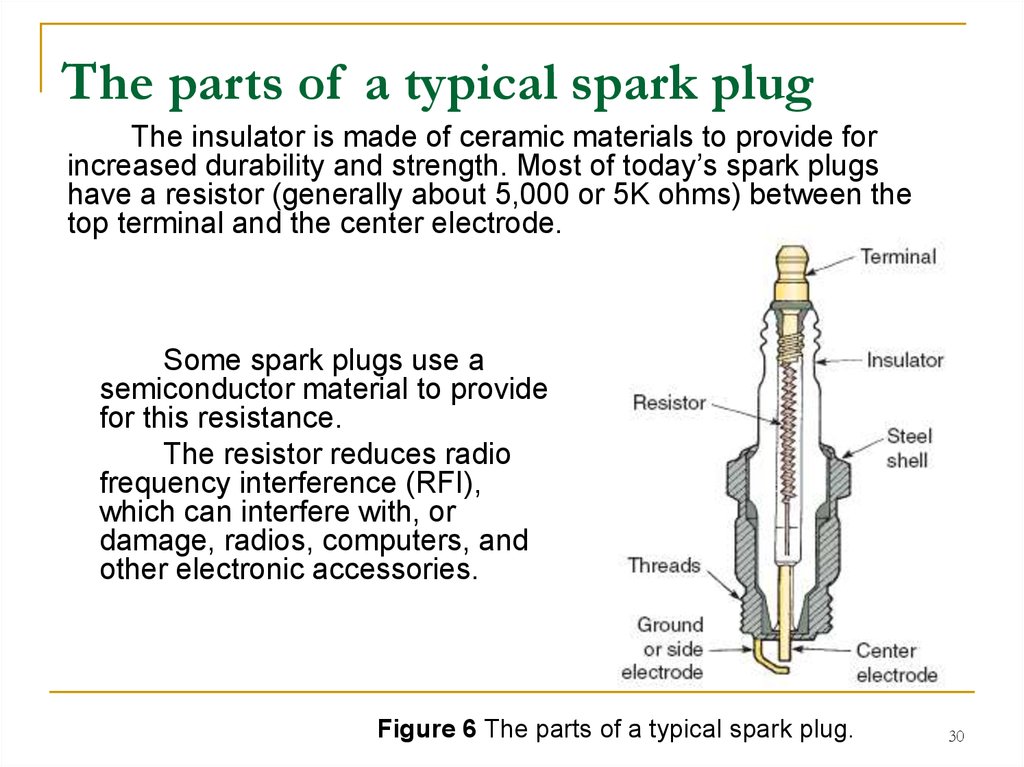
30.
The parts of a typical spark plugThe insulator is made of ceramic materials to provide for
increased durability and strength. Most of today’s spark plugs
have a resistor (generally about 5,000 or 5K ohms) between the
top terminal and the center electrode.
Some spark plugs use a
semiconductor material to provide
for this resistance.
The resistor reduces radio
frequency interference (RFI),
which can interfere with, or
damage, radios, computers, and
other electronic accessories.
Figure 6 The parts of a typical spark plug.
30
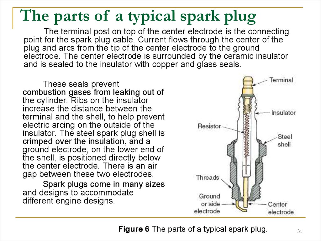
31.
The parts of a typical spark plugThe terminal post on top of the center electrode is the connecting
point for the spark plug cable. Current flows through the center of the
plug and arcs from the tip of the center electrode to the ground
electrode. The center electrode is surrounded by the ceramic insulator
and is sealed to the insulator with copper and glass seals.
These seals prevent
combustion gases from leaking out of
the cylinder. Ribs on the insulator
increase the distance between the
terminal and the shell, to help prevent
electric arcing on the outside of the
insulator. The steel spark plug shell is
crimped over the insulation, and a
ground electrode, on the lower end of
the shell, is positioned directly below
the center electrode. There is an air
gap between these two electrodes.
Spark plugs come in many sizes
and designs to accommodate
different engine designs.
Figure 6 The parts of a typical spark plug.
31
32. Spark Plug Reach
One important design characteristic of spark plugs is sparkplug reach (Figure 7). This refers to the length of the shell from the
contact surface at the seat to the bottom of the plug.
Figure 7 Spark plug reach
32
33. Abnormal combustion
Preignition is a term used to describe abnormal combustion,which is caused by something other than the heat of the spark. Spark
plug reach is crucial because the plug’s air gap must be properly placed
in the combustion chamber to produce the correct amount of heat.
If a plug’s reach
is too short, its electrodes
are in a pocket, and the
arc does not adequately
ignite the mixture. If the
plug’s reach is too long,
the exposed plug threads
can hit the piston or get
so hot they will ignite the
air–fuel mixture at the
wrong time.
Figure 7 Spark plug reach
33
34. Heat Range
When the engine isrunning, most of the spark
plug’s heat is concentrated on
the center electrode. Heat is
quickly dissipated from the
ground electrode because it’s
attached to the shell, which is
threaded into the cylinder
head (Figure 8) .
In liquid-cooled engines,
coolant circulating in the head
absorbs the heat and moves it
through the cooling system.
In air-cooled engines, the
heat is absorbed through the
cylinder head.
Figure 8 Spark plug heat range: hot versus cold.
34
35. Heat Range
The heat path for heat inthe center electrode is through
the insulator into the shell and
then to the cylinder head. The
heat range of a spark plug is
determined by the length of
the insulator before it contacts
the shell.
In a cold spark plug
(Cold Plug), there is a short
distance for the heat to travel
up the insulator to the shell.
This short path for heat means
the electrode and insulator
maintain little heat between
firings.
35
36. Heat Range
In a hot spark plug(Hot Plug), the heat travels
farther up the insulator before it
reaches the shell. This provides
a longer heat path and the plug
retains more heat. A spark plug
needs to retain enough heat to
clean itself between firings, but
not so much that it damages
itself or causes premature
ignition of the air–fuel mixture
in the cylinder.
The heat range is
indicated by a code imprinted
on the side of the spark plug,
usually on the porcelain
insulator.
Figure 8 Spark plug heat range: hot versus cold.
36
37. Spark Plug Gap
Correct spark plug air gap(Figure 9) is essential for
achieving optimum engine
performance and long plug life. A
gap that is too wide requires a
higher voltage to jump the gap.
If the required voltage is
greater than what is available,
misfiring results. Misfiring occurs
because of the inability of voltage
generated at the secondary coils
to jump the gap or maintain the
spark. Alternatively, a gap that is
too narrow requires lower
voltages and can lead to rough
idle and prematurely burned
electrodes, due to higher current
flow. Also, a misfire may occur if
a spark plug terminal is loose.
Figure 9 Spark plug gaps.
37
38. Electrodes
The materials used inthe construction of a spark
plug’s electrodes
determine the longevity,
power, and efficiency of
the plug. The construction
and shape of the tips of the
electrodes are also
important.
The electrodes of a
standard spark plug are
made out of copper, and
some use a copper–nickel
alloy. Copper is a good
electrical conductor and
offers resistance to
corrosion.
Platinum electrodes
are used to extend the life
of a spark plug (Figure 10).
Figure 10 A platinum-tipped spark plug.
38
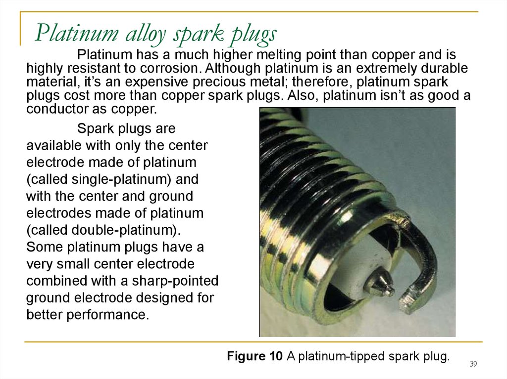
39.
Platinum alloy spark plugsPlatinum has a much higher melting point than copper and is
highly resistant to corrosion. Although platinum is an extremely durable
material, it’s an expensive precious metal; therefore, platinum spark
plugs cost more than copper spark plugs. Also, platinum isn’t as good a
conductor as copper.
Spark plugs are
available with only the center
electrode made of platinum
(called single-platinum) and
with the center and ground
electrodes made of platinum
(called double-platinum).
Some platinum plugs have a
very small center electrode
combined with a sharp-pointed
ground electrode designed for
better performance.
Figure 10 A platinum-tipped spark plug.
39
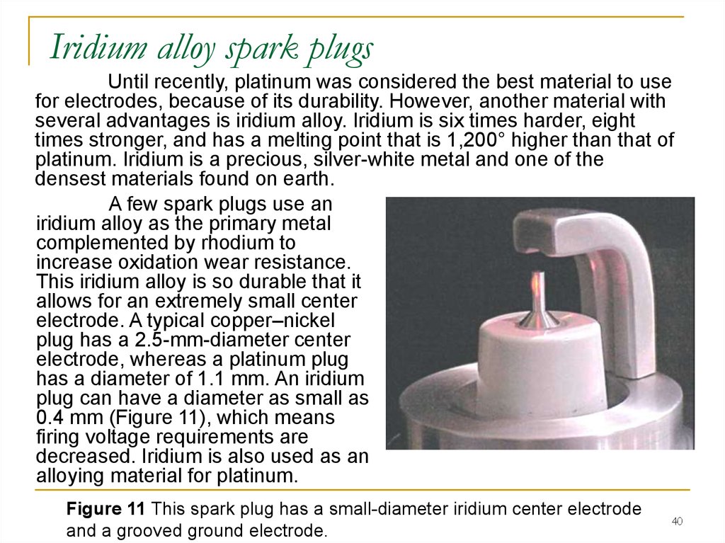
40.
Iridium alloy spark plugsUntil recently, platinum was considered the best material to use
for electrodes, because of its durability. However, another material with
several advantages is iridium alloy. Iridium is six times harder, eight
times stronger, and has a melting point that is 1,200° higher than that of
platinum. Iridium is a precious, silver-white metal and one of the
densest materials found on earth.
A few spark plugs use an
iridium alloy as the primary metal
complemented by rhodium to
increase oxidation wear resistance.
This iridium alloy is so durable that it
allows for an extremely small center
electrode. A typical copper–nickel
plug has a 2.5-mm-diameter center
electrode, whereas a platinum plug
has a diameter of 1.1 mm. An iridium
plug can have a diameter as small as
0.4 mm (Figure 11), which means
firing voltage requirements are
decreased. Iridium is also used as an
alloying material for platinum.
Figure 11 This spark plug has a small-diameter iridium center electrode
and a grooved ground electrode.
40
41. Electrode Designs
Spark plugs are available withmany shapes and numbers of electrodes.
When trying to ascertain the advantages
of each design, remember the spark is
caused by electrons moving across an air
gap. The electrons will always flow in the
direction of least electrical resistance.
Figure 11а Electrode designs.
41
42. Electrode Designs
The shape of the ground electrode may also be altered. A flat,conventional electrode tends to crush the spark, and the overall volume
of the flame front is smaller. A tapered ground electrode increases
flame front expansion and reduces the heat lost to the electrode.
Ground electrodes in
many power equipment engine
spark plugs have a U-groove
machined into the side that
faces the center electrode. The
U-groove allows the flame front
to fill the gap formed by the Ushape. This ball of fire develops
a larger and hotter flame front,
leading to a more complete
combustion.
Figure 11b U-groove ground electrode.
42
43. Triggering Switch Devices
Different types of ignition systems use different types of switchingdevices. There are two basic types of trigger switching devices used in
power equipment engine ignition systems.
1. Older ignition systems use a set of electrical contacts called
breaker points and a condenser to do the switching. Although rarely used
by any major manufacturer today, breaker points and condensers
continue to be in use in millions of older power equipment engines.
2. All modern power equipment engine systems, however, use
electronic components to do the switching.
In either system, the construction of the ignition coil and the spark
plug remain the same.
Figure 11c A basic transformer and digitally controlled transistorized ignition
system
43
44. Breaker Points and Condenser
Breaker points aremechanical contacts that are
used to stop and start the flow of
current through the primary
windings of the ignition coil. The
points are usually made of
tungsten, a very hard metal that
has a high resistance to heat.
One breaker point is
stationary (fixed), and the other
point is movable and insulated
from the stationary point. The
movable contact is mounted on a
spring-loaded arm, which holds
the points together.
Figure 12 shows a simplified
drawing of a set of breaker points.
Figure 12 A set of breaker points.
44
45. Breaker Points and Condenser
When the two breaker points touch, the ignition circuit is completeand the primary winding of the ignition coil is energized. When the end of
the spring-loaded movable breaker point is pressed, its contact end moves
apart from the stationary breaker point. This opens the circuit and the flow
of current stops. Each time the breaker points move apart, the spark plug
fires. This action is shown in Figure 13.
Figure 13 Shown is the action of breaker points in a simple ignition circuit.
45
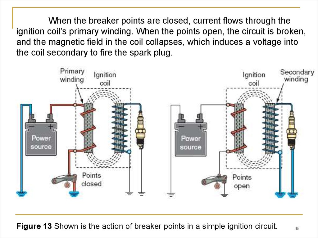
46.
When the breaker points are closed, current flows through theignition coil’s primary winding. When the points open, the circuit is broken,
and the magnetic field in the coil collapses, which induces a voltage into
the coil secondary to fire the spark plug.
Figure 13 Shown is the action of breaker points in a simple ignition circuit.
46
47. Breaker Points and Condenser
The spring mountedunder the movable point
holds the movable breaker
point against the cam. The
movable breaker point is
moved to the open position
by a turning cam with a
lobe. In most cases, the
cam is located on the
crankshaft. The lobe on the
cam forces the movable
breaker point away from the
stationary point, and the
spark plug fires.
Figure 12 A set of breaker points.
47
48. The condenser
Another important component of a breakerpoints system is thecondenser (also called a capacitor). Remember that each time the breaker
points touch, current flows through them.
Unless this current
flow is controlled in some
way, a spark or arc will
occur across the breaker
points as they move apart.
If this sparking is allowed to
occur, the breaker points
will arc, burn, and fail to
operate properly. The
points would also absorb
the electrical energy and
reduce the output voltage
of the ignition coil.
Figure 14 A typical battery-powered breaker point system.
48
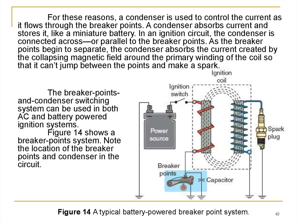
49.
For these reasons, a condenser is used to control the current asit flows through the breaker points. A condenser absorbs current and
stores it, like a miniature battery. In an ignition circuit, the condenser is
connected across—or parallel to the breaker points. As the breaker
points begin to separate, the condenser absorbs the current created by
the collapsing magnetic field around the primary winding of the coil so
that it can’t jump between the points and make a spark.
The breaker-pointsand-condenser switching
system can be used in both
AC and battery powered
ignition systems.
Figure 14 shows a
breaker-points system. Note
the location of the breaker
points and condenser in the
circuit.
Figure 14 A typical battery-powered breaker point system.
49
50. Electronic Trigger Devices
When an electronic ignition system is used in a power equipmentengine, a sensor is used to monitor the position of the crankshaft and
control the flow of current to the primary side of the ignition coil.
These sensors primarily include:
- magnetic-pulse generators and
- Hall-effect sensors.
An electronic switch completely eliminates the need for breaker
points and a condenser.
50
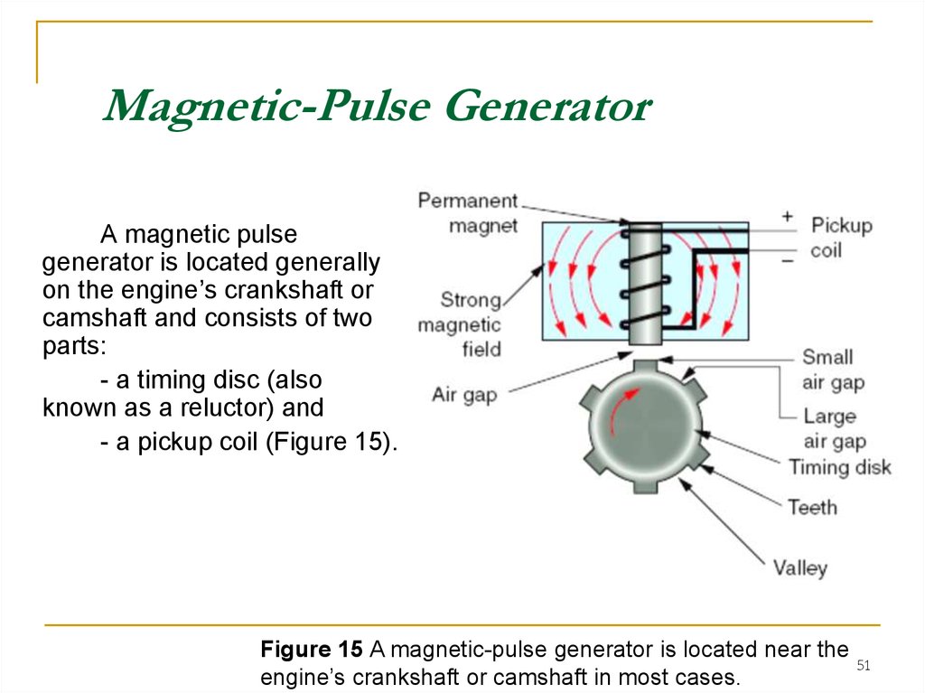
51.
Magnetic-Pulse GeneratorA magnetic pulse
generator is located generally
on the engine’s crankshaft or
camshaft and consists of two
parts:
- a timing disc (also
known as a reluctor) and
- a pickup coil (Figure 15).
Figure 15 A magnetic-pulse generator is located near the
engine’s crankshaft or camshaft in most cases.
51
52.
The pickup coil consists of a length of wire wrapped around apermanent magnet. The magnetic-pulse generator operates on the basic
electromagnetic principle that voltage can be induced only when a
conductor moves through a magnetic field. When the crankshaft or
camshaft is turned, the timing disc moves through the magnetic field.
As the timing disc
teeth approach the pickup
coil, a voltage is induced, and
this is used to control the
voltage to the primary side of
the ignition coil, just as the
opening and closing of the
contact points in the breakerpoints-and-condenser
switching system. A specific,
manufacturer-determined air
gap is required to ensure that
a signal of appropriate
strength is being produced.
Figure 15 A magnetic-pulse generator is located near the
engine’s crankshaft or camshaft in most cases.
52
53. Hall-Effect Sensor
The Hall-effect sensor or switch is the most commonly usedengine position sensor used in a power equipment engine that uses
an electronic ignition system. There are several reasons for this.
Unlike the magnetic pulse generator, the Hall-effect sensor
produces an accurate voltage signal across the entire rpm range of
the engine.
Furthermore, a
Hall-effect switch
produces a square-wave
pattern that is more
compatible with the
digital signals required
by onboard computers.
Figure 15a The Hall-effect sensor
53
54. Hall-Effect Sensor
Functionally, a Hall-effectswitch performs the same tasks as
a magnetic-pulse generator. But
the Hall-effect switch’s method of
generating voltage is quite unique.
It’s based, as you may guess, on
the Hall-effect principle. This
states that if a current is allowed
to flow through a thin conducting
material and that material is
exposed to a magnetic field,
voltage is produced in the
conductor. In essence, a Halleffect switch is either on or off. It
also uses a timing disc that is
used to switch the power on and
off as it passes by the sensor.
Figure 15b The Hall-effect principle
54
55. Stop Switch
Once an engine is started, it will keep running until it runs out offuel or is put under a heavy-enough load to cause it to stall. The stop
switch provides a convenient means to stop the engine.
Different types of stop switches are
found in different types of ignition systems.
In some power equipment engines, the
stop switch interrupts the flow of electricity
to the spark plug by giving the electrical
current an easier path to ground. This type
of switch consists of a button that grounds
the ignition system (Figure 4).
In other engines, the stop switch is
designed to prevent the flow of electricity
through the primary winding of the ignition
coil. This type of stop switch is connected
in series with the primary side of the
ignition coil. When you turn the switch to
the Off position, the ignition circuit is made
to open and the engine stops.
Figure 4 The basic components of an ignition system.
55
56. TYPES OF IGNITION SYSTEMS
Now that you understand how a basic ignition system in a powerequipment engine operates, let’s take a closer look at the construction
of some types of ignition systems. The two general types are the:
I. Breaker point ignition system
II. Electronic ignition system
Figure 15c A breaker point ignition and electronic ignition systems
56
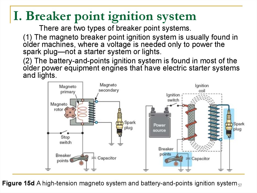
57.
I. Breaker point ignition systemThere are two types of breaker point systems.
(1) The magneto breaker point ignition system is usually found in
older machines, where a voltage is needed only to power the
spark plug—not a starter system or lights.
(2) The battery-and-points ignition system is found in most of the
older power equipment engines that have electric starter systems
and lights.
Figure 15d A high-tension magneto system and battery-and-points ignition system 57
58. (1)Magneto Ignition Systems
In magneto ignition systems in older power equipment engines withoutany lights or a battery, the AC source may have the sole function of
operating the ignition system. In other models that include lighting systems,
one AC generator coil may be used for ignition, and another for lighting. All
magneto ignition systems operate without a battery, or are independent of
the battery if one is used for the operation of other electrical functions.
The magneto ignition system
uses permanent magnets installed on
the engine’s flywheel/rotor. Magnetos
are classified as being one of three
types:
■ High tension
■ Low tension
■ Energy transfer
Figure 16 A high-tension magneto system
58
59. High-Tension Magneto Ignition System
High-tension magnetoignition systems (Figure
16) haven’t been in use in
power equipment engines
for quite a few years, but
they were once the most
popular ignition system,
found in small engines.
Figure 16 A high-tension magneto system.
59
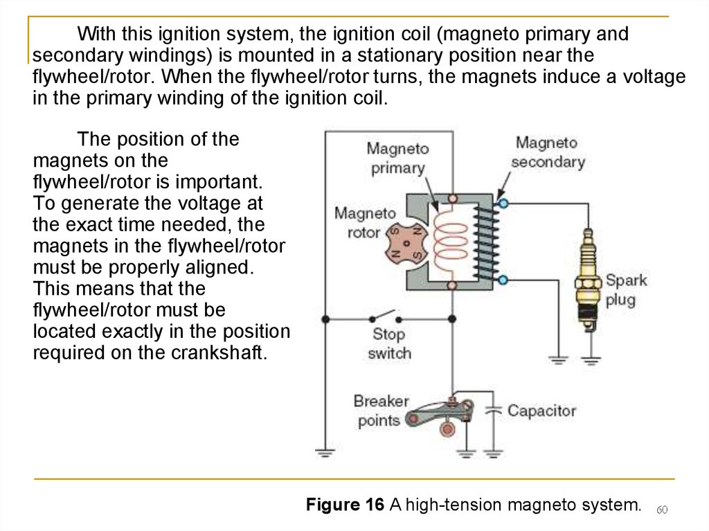
60.
With this ignition system, the ignition coil (magneto primary andsecondary windings) is mounted in a stationary position near the
flywheel/rotor. When the flywheel/rotor turns, the magnets induce a voltage
in the primary winding of the ignition coil.
The position of the
magnets on the
flywheel/rotor is important.
To generate the voltage at
the exact time needed, the
magnets in the flywheel/rotor
must be properly aligned.
This means that the
flywheel/rotor must be
located exactly in the position
required on the crankshaft.
Figure 16 A high-tension magneto system.
60
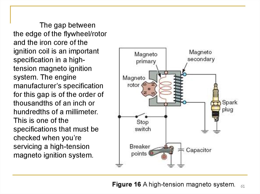
61.
The gap betweenthe edge of the flywheel/rotor
and the iron core of the
ignition coil is an important
specification in a hightension magneto ignition
system. The engine
manufacturer’s specification
for this gap is of the order of
thousandths of an inch or
hundredths of a millimeter.
This is one of the
specifications that must be
checked when you’re
servicing a high-tension
magneto ignition system.
Figure 16 A high-tension magneto system.
61
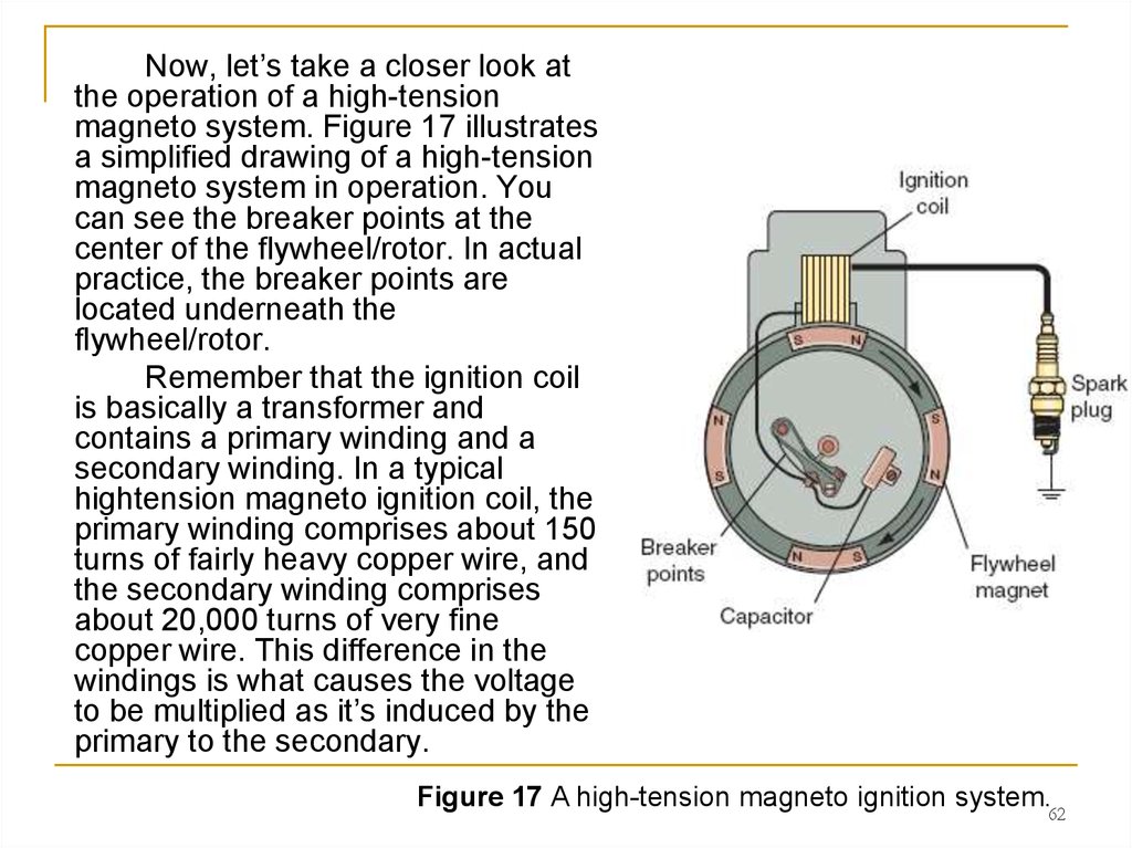
62.
Now, let’s take a closer look atthe operation of a high-tension
magneto system. Figure 17 illustrates
a simplified drawing of a high-tension
magneto system in operation. You
can see the breaker points at the
center of the flywheel/rotor. In actual
practice, the breaker points are
located underneath the
flywheel/rotor.
Remember that the ignition coil
is basically a transformer and
contains a primary winding and a
secondary winding. In a typical
hightension magneto ignition coil, the
primary winding comprises about 150
turns of fairly heavy copper wire, and
the secondary winding comprises
about 20,000 turns of very fine
copper wire. This difference in the
windings is what causes the voltage
to be multiplied as it’s induced by the
primary to the secondary.
Figure 17 A high-tension magneto ignition system.62
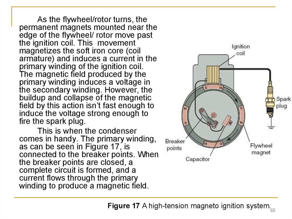
63.
As the flywheel/rotor turns, thepermanent magnets mounted near the
edge of the flywheel/ rotor move past
the ignition coil. This movement
magnetizes the soft iron core (coil
armature) and induces a current in the
primary winding of the ignition coil.
The magnetic field produced by the
primary winding induces a voltage in
the secondary winding. However, the
buildup and collapse of the magnetic
field by this action isn’t fast enough to
induce the voltage strong enough to
fire the spark plug.
This is when the condenser
comes in handy. The primary winding,
as can be seen in Figure 17, is
connected to the breaker points. When
the breaker points are closed, a
complete circuit is formed, and a
current flows through the primary
winding to produce a magnetic field.
Figure 17 A high-tension magneto ignition system.63
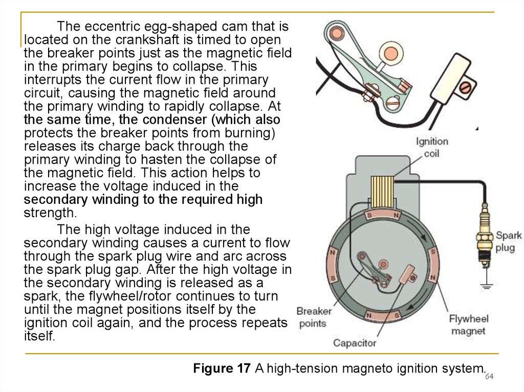
64.
The eccentric egg-shaped cam that islocated on the crankshaft is timed to open
the breaker points just as the magnetic field
in the primary begins to collapse. This
interrupts the current flow in the primary
circuit, causing the magnetic field around
the primary winding to rapidly collapse. At
the same time, the condenser (which also
protects the breaker points from burning)
releases its charge back through the
primary winding to hasten the collapse of
the magnetic field. This action helps to
increase the voltage induced in the
secondary winding to the required high
strength.
The high voltage induced in the
secondary winding causes a current to flow
through the spark plug wire and arc across
the spark plug gap. After the high voltage in
the secondary winding is released as a
spark, the flywheel/rotor continues to turn
until the magnet positions itself by the
ignition coil again, and the process repeats
itself.
Figure 17 A high-tension magneto ignition system.64
65. Low-Tension Magneto Ignition System
Not found often in power equipment engines, the low-tensionmagneto system is similar in operation to the high-tension magneto system.
The main difference is that
the low-tension system uses a
separate ignition coil. The
breaker points in both the highand low-tension magneto ignition
systems are connected in series
with the primary circuit. When the
breaker points are closed in the
low-tension magneto system, the
primary circuit is completed
(Figure 18). As the magneto rotor
turns, AC (alternating current) is
generated in the magneto
windings and flows through the
ignition coil primary winding. The
primary winding in the ignition
coil produces a magnetic field in
the ignition coil.
Figure 18 A low-tension magneto ignition system.
65
66. Energy-Transfer Ignition System
The energy-transfer ignition system (Figure 19) is another typeof magneto ignition system found in power equipment engines.
The primary difference
between the energytransfer system and the
magneto systems is that the
breaker points are
connected in parallel with
the primary circuit instead
of in series. By having the
points wired in parallel, the
primary winding in the
ignition coil induces voltage
into the secondary windings
by using a rapid buildup of
a magnetic field instead of
a rapid collapse of the field.
Figure 19 An energy-transfer ignition system.
66
67. (2) Battery-and-Points Ignition Systems
Now, let’s look at a battery-and-points ignition system. Rememberthat battery ignition systems were used in older street-type power
equipment engines.
In a battery-and-points ignition
system, a battery is used to provide
power to the ignition coil instead of a
magneto; however, the remainder of
the system is similar to the magneto
systems we’ve discussed. The
battery-and-points system (Figure
20) uses the same type of breaker
points, condenser, and spark plug
as magneto-type ignition systems.
The battery used in this type of
system is the lead acid storage
battery. Besides providing electricity
to power the ignition coil, the battery
may also be used to power lights,
electric starter systems, and other
accessories.
Figure 20 The battery-and-points system
67
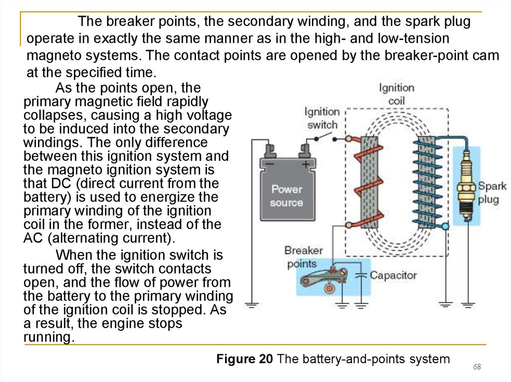
68.
The breaker points, the secondary winding, and the spark plugoperate in exactly the same manner as in the high- and low-tension
magneto systems. The contact points are opened by the breaker-point cam
at the specified time.
As the points open, the
primary magnetic field rapidly
collapses, causing a high voltage
to be induced into the secondary
windings. The only difference
between this ignition system and
the magneto ignition system is
that DC (direct current from the
battery) is used to energize the
primary winding of the ignition
coil in the former, instead of the
AC (alternating current).
When the ignition switch is
turned off, the switch contacts
open, and the flow of power from
the battery to the primary winding
of the ignition coil is stopped. As
a result, the engine stops
running.
Figure 20 The battery-and-points system
68
69. II. Electronic Pointless Ignition Systems
Breaker-points-and-condenser ignition systems have been in usefor many years, but you may see these types of ignition systems only
in older power equipment engines. Newer power equipment engines
come with electronic ignition systems. The reason for this is that
mechanical breaker points eventually wear out and fail.
The result is poor
engine performance at
first and ultimately, total
ignition failure. Electronic
ignition systems are
durable because they use
permanent magnets,
electronic sensors,
diodes, transistors in
place of mechanical
switching components.
Figure 20a The breaker-points-and-condenser ignition systems
69
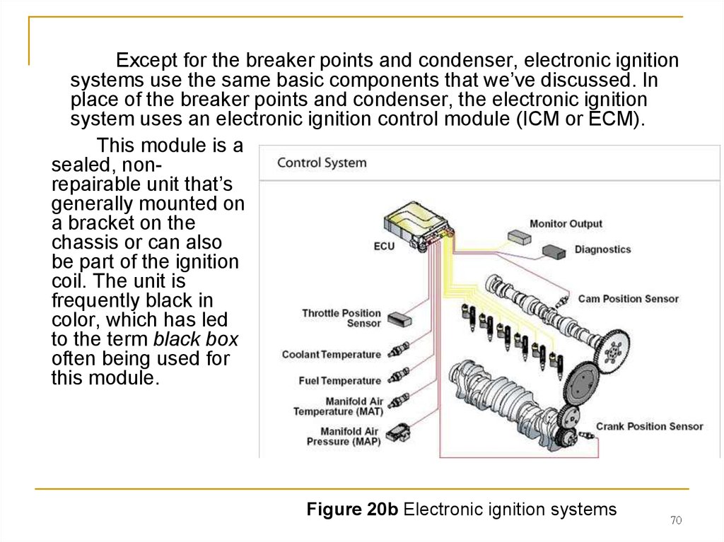
70.
Except for the breaker points and condenser, electronic ignitionsystems use the same basic components that we’ve discussed. In
place of the breaker points and condenser, the electronic ignition
system uses an electronic ignition control module (ICM or ECM).
This module is a
sealed, nonrepairable unit that’s
generally mounted on
a bracket on the
chassis or can also
be part of the ignition
coil. The unit is
frequently black in
color, which has led
to the term black box
often being used for
this module.
Figure 20b Electronic ignition systems
70
71. Electronic Pointless Ignition Systems
Other than the rotor and its magnets, electronic ignition systems haveno moving parts; so the performance of the system doesn’t decline through
operation. ICMs are resistant to moisture, oil, and dirt. Although resistant to
outside conditions, water can get into modules and cause interruptions or
failure to the ignition system.
However, in general, they’re reliable, don’t require adjustments, and
have long life spans. An electronic ignition system provides easy starting
and smooth, consistent power during the operation of the power equipment
engine.
Figure 21 A typical capacitor discharge ignition (CDI) system.
71
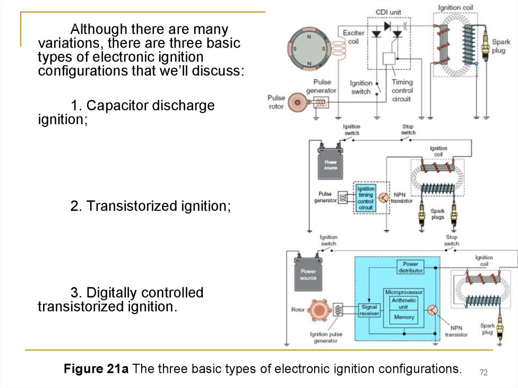
72.
Although there are manyvariations, there are three basic
types of electronic ignition
configurations that we’ll discuss:
1. Capacitor discharge
ignition;
2. Transistorized ignition;
3. Digitally controlled
transistorized ignition.
Figure 21a The three basic types of electronic ignition configurations.
72
73. 1. Capacitor Discharge Ignition Systems
The electronic ignition system most often used in small powerequipment engines is the CDI system.
Figure 21 A typical capacitor discharge ignition (CDI) system.
73
74.
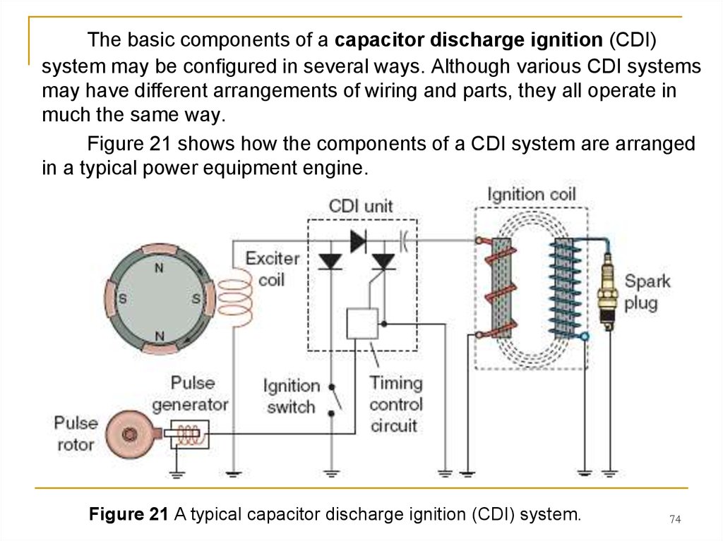
The basic components of a capacitor discharge ignition (CDI)system may be configured in several ways. Although various CDI systems
may have different arrangements of wiring and parts, they all operate in
much the same way.
Figure 21 shows how the components of a CDI system are arranged
in a typical power equipment engine.
Figure 21 A typical capacitor discharge ignition (CDI) system.
74
75.
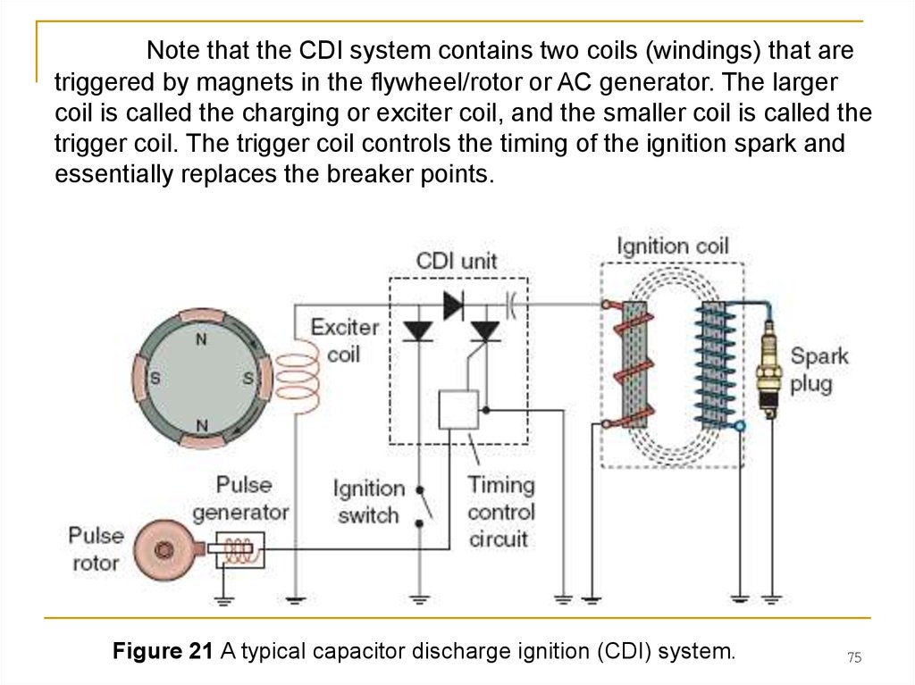
Note that the CDI system contains two coils (windings) that aretriggered by magnets in the flywheel/rotor or AC generator. The larger
coil is called the charging or exciter coil, and the smaller coil is called the
trigger coil. The trigger coil controls the timing of the ignition spark and
essentially replaces the breaker points.
Figure 21 A typical capacitor discharge ignition (CDI) system.
75
76.
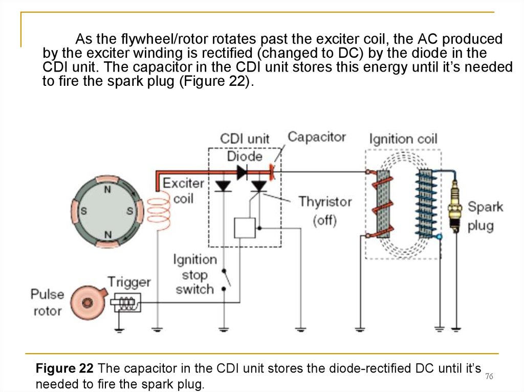
As the flywheel/rotor rotates past the exciter coil, the AC producedby the exciter winding is rectified (changed to DC) by the diode in the
CDI unit. The capacitor in the CDI unit stores this energy until it’s needed
to fire the spark plug (Figure 22).
Figure 22 The capacitor in the CDI unit stores the diode-rectified DC until it’s 76
needed to fire the spark plug.
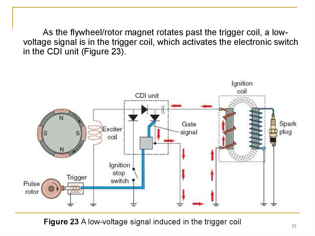
77.
As the flywheel/rotor magnet rotates past the trigger coil, a lowvoltage signal is in the trigger coil, which activates the electronic switchin the CDI unit (Figure 23).
Figure 23 A low-voltage signal induced in the trigger coil
77
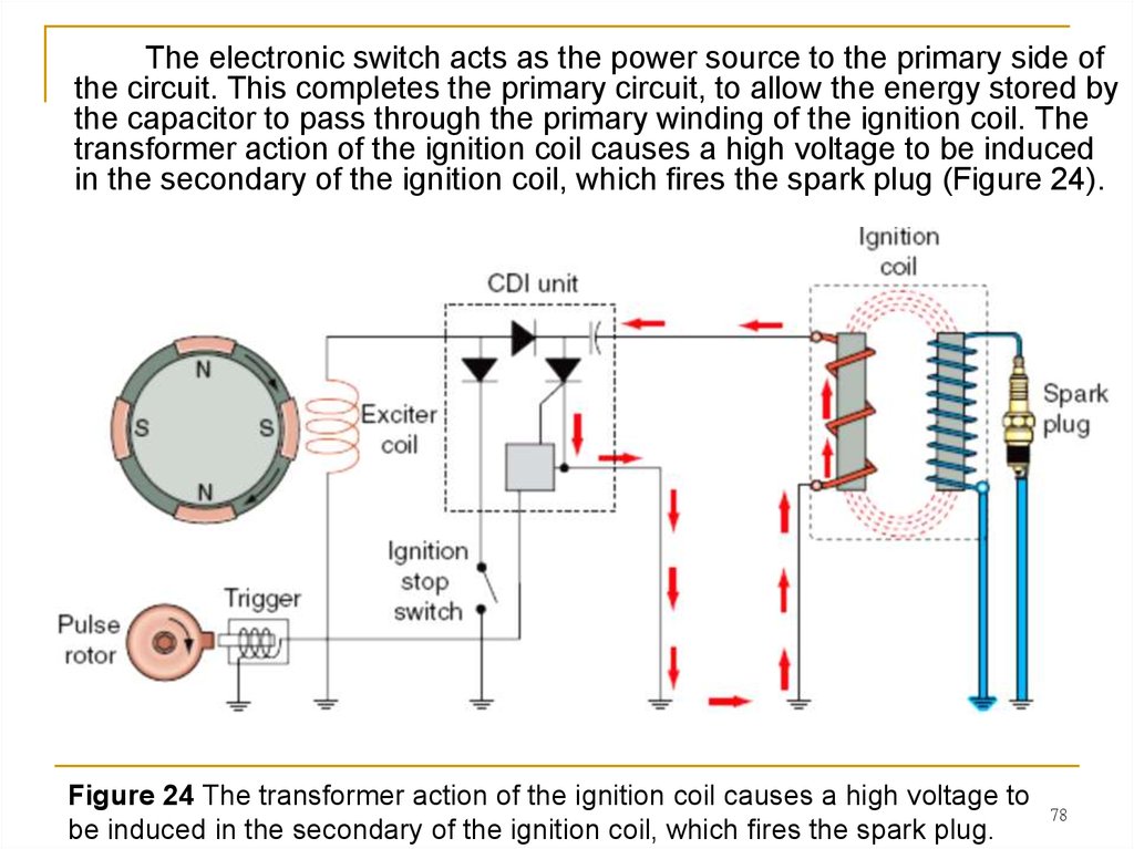
78.
The electronic switch acts as the power source to the primary side ofthe circuit. This completes the primary circuit, to allow the energy stored by
the capacitor to pass through the primary winding of the ignition coil. The
transformer action of the ignition coil causes a high voltage to be induced
in the secondary of the ignition coil, which fires the spark plug (Figure 24).
Figure 24 The transformer action of the ignition coil causes a high voltage to
be induced in the secondary of the ignition coil, which fires the spark plug.
78
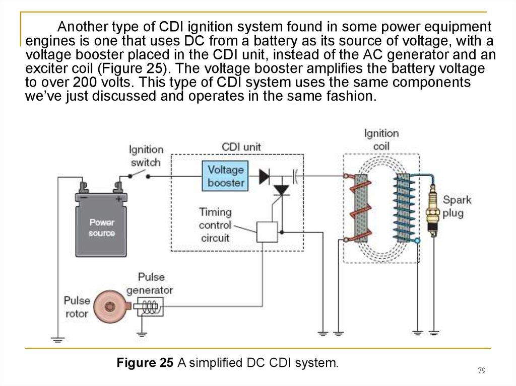
79.
Another type of CDI ignition system found in some power equipmentengines is one that uses DC from a battery as its source of voltage, with a
voltage booster placed in the CDI unit, instead of the AC generator and an
exciter coil (Figure 25). The voltage booster amplifies the battery voltage
to over 200 volts. This type of CDI system uses the same components
we’ve just discussed and operates in the same fashion.
Figure 25 A simplified DC CDI system.
79
80. 2.Transistorized Ignition Systems
Not popular but still used in some power equipment engines, thetransistorized ignition system (Figure 26) operates by controlling the flow
of electricity to the primary coil of the ignition. With this type of ignition
system, transistors are contained within the ICM and are used to supply
electricity to the primary coil.
When the voltage
level in the primary reaches
a certain level, a second
transistor turns off the first
transistor. This causes the
magnetic field around the
primary coil to collapse,
which creates the high
voltage across the
secondary coil. The high
voltage is then discharged
across the spark plug.
Figure 26 A transistorized ignition system.
80
81. 3. Digitally Controlled Transistorized Ignition Systems
The digitally controlled transistorized ignition system is a type ofTransistorized Pointless Ignition (TPI) that’s found in most power
equipment engine applications today (Figure 27).
Figure 27 A digitally controlled transistorized ignition system.
81
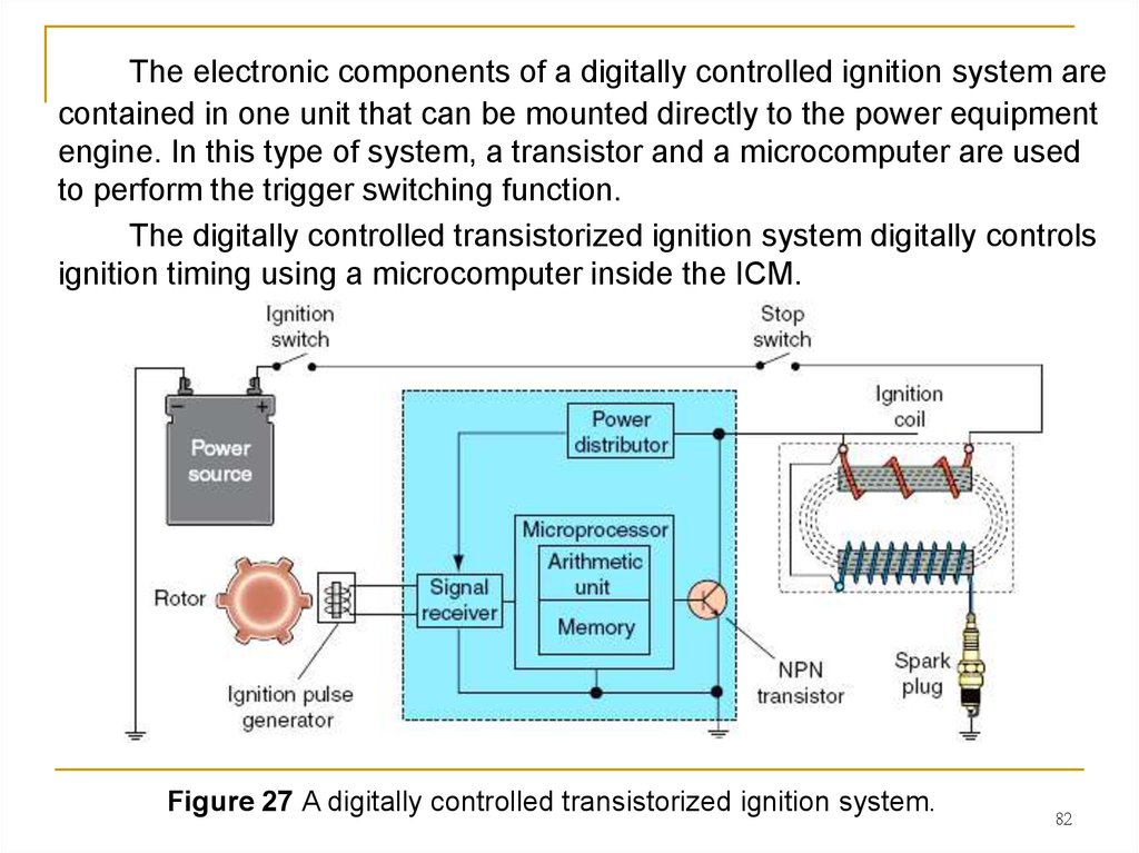
82.
The electronic components of a digitally controlled ignition system arecontained in one unit that can be mounted directly to the power equipment
engine. In this type of system, a transistor and a microcomputer are used
to perform the trigger switching function.
The digitally controlled transistorized ignition system digitally controls
ignition timing using a microcomputer inside the ICM.
Figure 27 A digitally controlled transistorized ignition system.
82
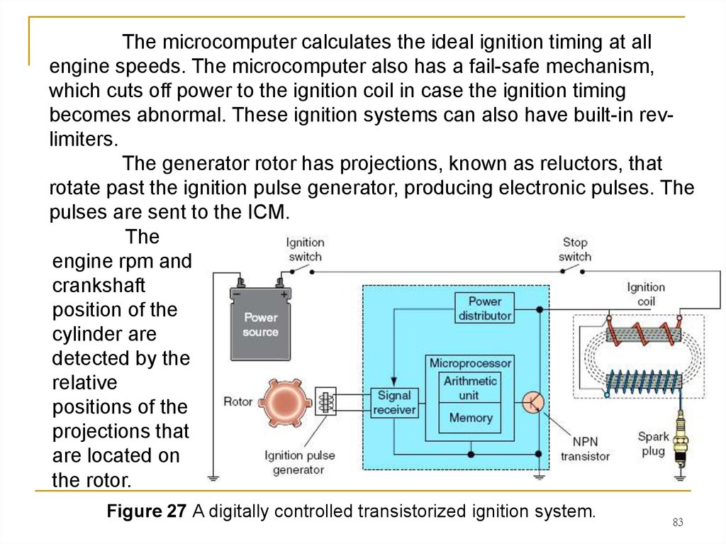
83.
The microcomputer calculates the ideal ignition timing at allengine speeds. The microcomputer also has a fail-safe mechanism,
which cuts off power to the ignition coil in case the ignition timing
becomes abnormal. These ignition systems can also have built-in revlimiters.
The generator rotor has projections, known as reluctors, that
rotate past the ignition pulse generator, producing electronic pulses. The
pulses are sent to the ICM.
The
engine rpm and
crankshaft
position of the
cylinder are
detected by the
relative
positions of the
projections that
are located on
the rotor.
Figure 27 A digitally controlled transistorized ignition system.
83
84.
The ICM consists of a power distributor, a signal receiver, and amicrocomputer. The power distributor distributes battery voltage to the
ICM when the ignition switch is turned to the On position and the engine
stop switch is in the Run position.
The signal receiver uses the electronic pulse from the ignition
pulse generator and converts the pulse signal to a digital signal. The
digital signal is sent to the microcomputer, which has a memory unit and
an arithmetic unit. The memory unit stores predetermined
characteristics of the timing for different engine speeds and crankshaft
positions.
It then
determines
when to turn
the transistor
on and off to
achieve the
correct spark
plug firing
time.
Figure 27 A digitally controlled transistorized ignition system.
84
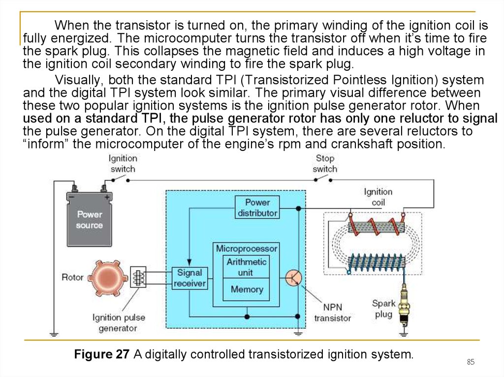
85.
When the transistor is turned on, the primary winding of the ignition coil isfully energized. The microcomputer turns the transistor off when it’s time to fire
the spark plug. This collapses the magnetic field and induces a high voltage in
the ignition coil secondary winding to fire the spark plug.
Visually, both the standard TPI (Transistorized Pointless Ignition) system
and the digital TPI system look similar. The primary visual difference between
these two popular ignition systems is the ignition pulse generator rotor. When
used on a standard TPI, the pulse generator rotor has only one reluctor to signal
the pulse generator. On the digital TPI system, there are several reluctors to
“inform” the microcomputer of the engine’s rpm and crankshaft position.
Figure 27 A digitally controlled transistorized ignition system.
85
86. Summary
1. The ignition system has three main functions:- first, it must generate an electrical spark that has
enough heat to ignite the air-fuel mixture in the combustion chamber;
- second, it must maintain that spark long enough to allow
for the combustion of all the air and fuel in the cylinder;
- lastly, it must deliver a spark to the cylinder so
combustion can begin at the right time during each compression stroke
of the piston.
2. The main components of an ignition system are the power
source, ignition switch, ignition coil, spark plug, triggering switch, and
stop switch.
3. All ignition systems use a primary coil and a secondary coil.
The current in the primary coil induces a relatively large voltage in the
secondary, to create a high output voltage to the spark plug.
86
87. Summary
4. There are two general types of ignition systems:- breaker point and
- electronic ignition.
5. There are four types of breaker point systems:
- high-tension magneto,
- low-tension magneto,
- energy transfer, and
- battery point.
6. There are three basic types of electronic ignition systems:
- capacitive discharge,
- transistorized, and
- digitally controlled transistorized systems.
87