 Safety Systems")


 БЖД
БЖДПохожие презентации:


")


Safety Fundamentals for NPPs
1. Course: Fundamentals of AES-2006 technology Module 05: VVER (AES-2006) Safety Systems
Rosatom State Atomic Energy CorporationCourse: Fundamentals of AES-2006 technology
Module 05: VVER (AES-2006) Safety Systems
Date
June, 2017
Prepared by:
Denis Podoliakin
Reviewed by:
Fedor Karmanov
Final methodological control by:
Natalia Shulepova,
Maria Melnikova
Translation quality checked by:
Natalia Shulepova,
Maria Melnikova
Based on materials prepared by:
Rosatom Technical Academy (RosatomTech)
2.
Training ObjectivesTerminal Training Objectives:
1. To list the safety systems used to carry out functions for DBC and DEC-A conditions
2. To list the AES-2006/E safety systems used in Hanhikivi-1 NPP
Enabling Training Objectives:
1. To familiarize trainees with the basic requirements and nuclear safety approaches
implementation in the AES-2006/E
2. To describe the defence-in-depth concept implementation for AES-2006/E
3. To list the VVER safety systems
4. To describe the principles of safety system operation of the NPP with VVER
3.
Content1. Safety fundamentals for NPPs
2. Design and Safety Functions
3. VVER Safety Systems
A. Reactivity control
B. Heat removal from nuclear fuel
C. Localization of activity
4. Safety Fundamentals for NPPs
Rosatom State Atomic Energy CorporationSafety Fundamentals for NPPs
5.
Definition of «Safety»I. Safety is the state of being "safe" (from French sauf), the condition of being protected
from harm or other non-desirable outcomes. Safety can also refer
to the control of recognized hazards in order to achieve an acceptable level of risk.
[Wikipedia]
II. “Safety” means the protection of people and the environment against radiation risks,
and the safety of facilities and activities that give rise to radiation risks. “Safety” as used
here and in the IAEA safety standards includes the safety of nuclear installations,
radiation safety, the safety of radioactive waste management and safety in the transport
of radioactive material; it does not include non-radiation-related aspects of safety. [IAEA]
III. [Nuclear] safety
The achievement of proper operating conditions, prevention of accidents
or mitigation of accident consequences, resulting in protection of workers,
the public and the environment from undue radiation hazards. [IAEA]
6.
Definition of «Safety»IV. Safety – the condition of being protected from or unlikely to cause danger, risk,
or injury. [Oxford dictionary]
V. Safety is a property of nuclear power plants to provide reliable protection
of personnel, the public and the environment from the unacceptable radiation exposure
in accordance with federal norms and rules in the use of atomic energy. [www.rosatom.ru]
VI. Safety – the use of nuclear energy must be safe; it shall not cause injury to people,
or damage to the environment or property. [Finland, Nuclear Energy Act 11.12.1987/990.
Section 6 – Safety]
7.
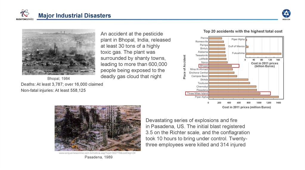
Major Industrial DisastersDeaths: At least 3,787; over 16,000 claimed
Non-fatal injuries: At least 558,125
Top 20 accidents with the highest total cost
Place of Accident
Bhopal, 1984
An accident at the pesticide
plant in Bhopal, India, released
at least 30 tons of a highly
toxic gas. The plant was
surrounded by shanty towns,
leading to more than 600,000
people being exposed to the
deadly gas cloud that night
Pernis
Romeoville
Pampa
Bintulu
Alabama
Tessaloniki
LaMede
Norco
Bhopal
Mina Al-Ahmadi
Enchova Central
Campos Basin
Skikda
Toulouse
Chernobyl
Pasadena
Three Miles Island
Piper Alpha
Piper Alpha
Gulf of Mexico
Fukushima
Cost in 2011 prices
(billion Euros)
Cost in 2011 prices (million Euros)
Devastating series of explosions and fire
in Pasadena, US. The initial blast registered
3.5 on the Richter scale, and the conflagration
took 10 hours to bring under control. Twentythree employees were killed and 314 injured
www.ariquemesonline.com.br/noticia.asp?cod=302779&codDep=24
Pasadena, 1989
8.
ResponsibilityThe organisation operating a nuclear power plant shall be
responsible for the plant’s safe operation under all operational
states and accident conditions
Personnel shall be encouraged to perform responsible work,
and to identify, report, and eliminate factors endangering safety.
Personnel shall be given the opportunity to contribute
to the continuous improvement of safety
SAHARA principle – safety as high as reasonably achievable
9. Design and Safety Functions
Rosatom State Atomic Energy CorporationDesign and Safety Functions
10.
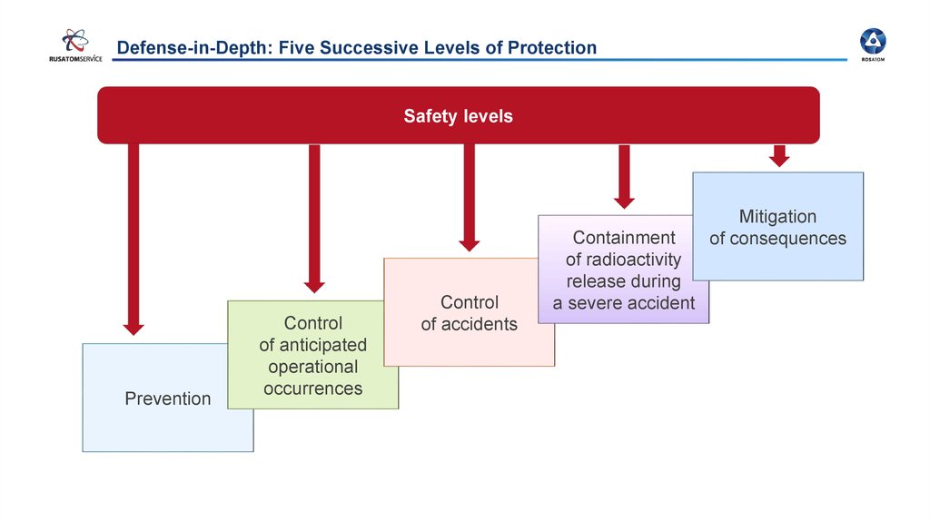
Defense-in-Depth: Five Successive Levels of ProtectionSafety levels
Prevention
Control
of anticipated
operational
occurrences
Control
of accidents
Containment
of radioactivity
release during
a severe accident
Mitigation
of consequences
11.
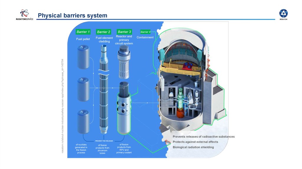
rosatom.ru/about-nuclear-industry/safety-russian-npp/index.php?sphrase_id=145794Physical barriers system
Barrier 1
Barrier 2
Barrier 3
Barrier 4
Fuel pellet
Fuel element
cladding
Reactor and
primary
circuit system
Containment
Prevents releases of radioactive substances
PREVENT THE RELEASE
of nuclides
generated in
the fission
process
of fission
products from
zirconium
tubes
Protects against external effects
of fission
products from
RPV and
primary coolant
Biological radiation shielding
12.
DiD PrincipleDefense-in-depth is a philosophy
to ensure nuclear safety
Physical barriers
Organizational and technical measures
Level 1. Prevention of abnormal operation and failures
Level 2. Control of abnormal operation and detection of failures
Level 3. Control of accidents
Fuel matrix (pallets)
Fuel rod cladding
Reactor coolant system boundary
Containment
New safety requirements
Level 4. Severe accident management
Level 5. Emergency planning
Population
and environment
protection
13.
Design Basis Conditions (DBC) and Design Extension Conditions (DEC)Severe
Accidents
Potential Radiological Impact
CCF,
EEI*
SA
Category 2
DBA
Accidents
with core
melt
DECA,B,C DBC-4
Category 1
DBA
AOO
NOC
DBC-3
Accidents without core
melt
10-7
In the deterministic safety analysis, as per
the level of possible negative consequences
and an occurrence probability, the list
of Design Conditions is divided into several
categories
10-6
10-5
DBC-2
10-4
DBC-1
*) DBA – Design Basis Accident
CCF – Common Cause Failure events
EEI – Extremely External Impacts
1
Frequency (per reactor and per year)
Acceptance criteria for each category of design conditions
Safety analysis to justify the acceptance criteria
www.iaea.org/INPRO/7th_Dialogue_Forum/Rosatom_1.pdf
14.
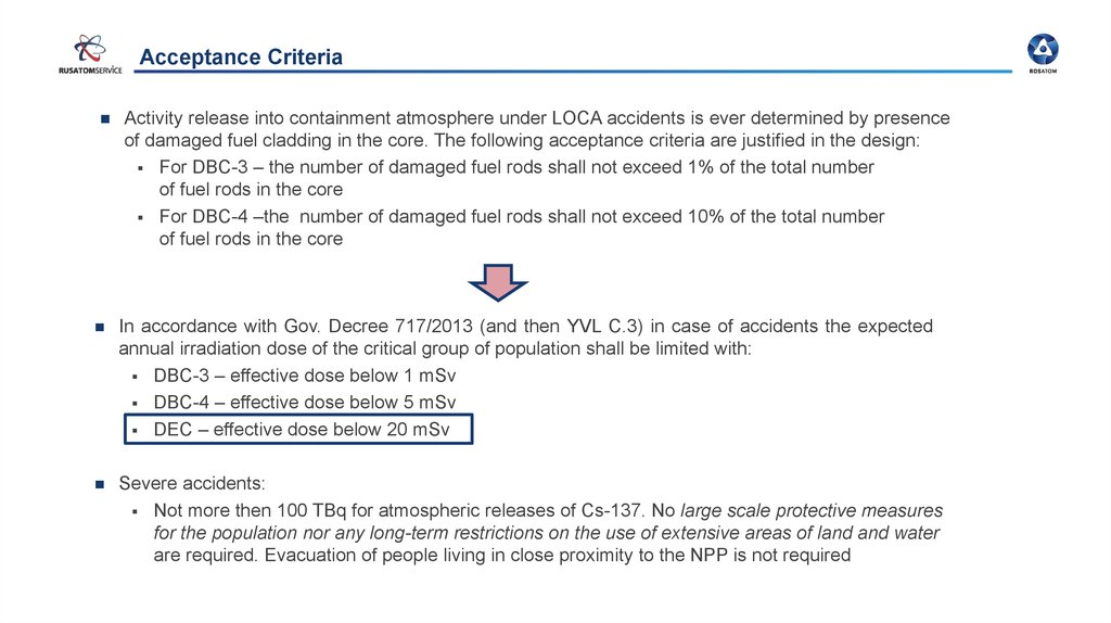
Acceptance CriteriaActivity release into containment atmosphere under LOCA accidents is ever determined by presence
of damaged fuel cladding in the core. The following acceptance criteria are justified in the design:
For DBC-3 – the number of damaged fuel rods shall not exceed 1% of the total number
of fuel rods in the core
For DBC-4 –the number of damaged fuel rods shall not exceed 10% of the total number
of fuel rods in the core
In accordance with Gov. Decree 717/2013 (and then YVL C.3) in case of accidents the expected
annual irradiation dose of the critical group of population shall be limited with:
DBC-3 – effective dose below 1 mSv
DBC-4 – effective dose below 5 mSv
DEC – effective dose below 20 mSv
Severe accidents:
Not more then 100 TBq for atmospheric releases of Cs-137. No large scale protective measures
for the population nor any long-term restrictions on the use of extensive areas of land and water
are required. Evacuation of people living in close proximity to the NPP is not required
15.
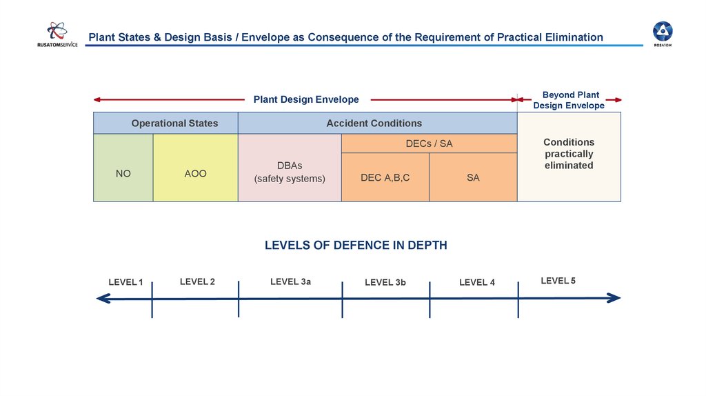
Plant States & Design Basis / Envelope as Consequence of the Requirement of Practical EliminationBeyond Plant
Design Envelope
Plant Design Envelope
Operational States
Accident Conditions
Conditions
practically
eliminated
DECs / SA
NO
AOO
DBAs
(safety systems)
DEC A,B,C
SA
LEVELS OF DEFENCE IN DEPTH
LEVEL 1
LEVEL 2
LEVEL 3a
LEVEL 3b
LEVEL 4
LEVEL 5
16.
ConditionsFundamental Safety Functions
Operational plant states
During and after any design
basis accident
In emergency conditions
arising in the case of beyond
design basis accidents
Functions
Control of reactivity
Removal of heat from the reactor
Confinement of radioactive material, shielding against radiation and control of planned
radioactive releases, as well as limitation of accidental radioactive releases
17.
Rosatom State Atomic Energy CorporationVVER Safety Systems
18.
DiD level 3Level 3 is divided into levels 3a and 3b:
Level 3a includes systems ensuring execution of safety functions during accidents
of classes 1 and 2 (DBC-3 and DBC-4)
Level 3b includes systems ensuring execution of safety functions under the conditions
when level 3a systems cannot perform their functions as a result of common-cause
failures, external effects or other complex accident sequences
19.
Accident managementAccident management strategy includes:
bringing the NPP to the controlled state
bringing the NPP to the safe state
Controlled state is the state when the fission chain reaction stops and residual heat
is removed from the fuel
Safe state is the state when the fission chain reaction stops, residual heat is removed
from the fuel and there is no excessive pressure within physical barriers 3 and 4
20.
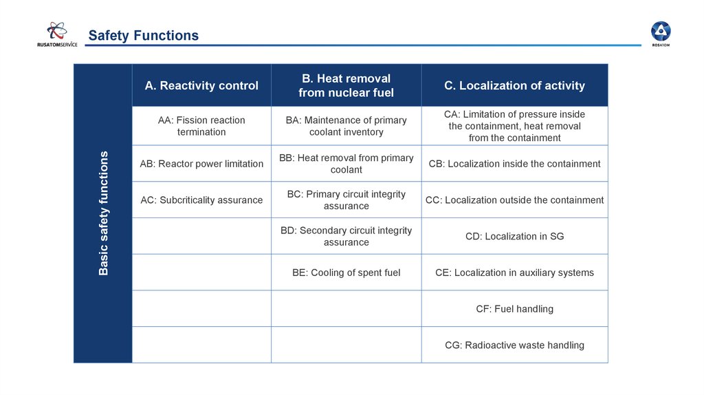
Basic safety functionsBasic safety functions
Safety Functions
A. Reactivity control
B. Heat removal
from nuclear fuel
C. Localization of activity
AA: Fission reaction
termination
BA: Maintenance of primary
coolant inventory
CA: Limitation of pressure inside
the containment, heat removal
from the containment
AB: Reactor power limitation
BB: Heat removal from primary
coolant
CB: Localization inside the containment
AC: Subcriticality assurance
BC: Primary circuit integrity
assurance
CC: Localization outside the containment
BD: Secondary circuit integrity
assurance
CD: Localization in SG
BE: Cooling of spent fuel
CE: Localization in auxiliary systems
CF: Fuel handling
CG: Radioactive waste handling
21.
Design principles of safety systemsSafety systems are designed in accordance with the principles ensuring their
reliability and failure tolerance:
Redundancy principle
system redundancy – application of multi-train systems
component redundancy – component and equipment redundancy within system trains
Independence principle
physical separation
functional separation
Diversity principle
application of means based on different principles of operation
different physical variables
different operating conditions
different equipment manufacturers
Reliability of safety systems and equipment is provided by the quality of their
design, manufacturing and maintenance. It is expressed by their safety class
22.
Монтажеру: выделить все обозначенные узлы на словах лектора про many safety systems, чтобы показать что их многоGeneral diagram of safety systems and means
Passive hydrogen recombiners JMT
PHRS tank JNB
Spray system header JMN
Containment PHRS condenser
ECCS hydroaccumulators JNG-2
PHRS steam generators JMP
Pressurizer PORV JEV
Reactor JAA
Containment
Pressurizer JEF
RCPS JEB
Relief tank JEG
Core catcher JMR
SG SV and BRU-A LBA
Sump tank (low-concentrated
borated water inventory) JNK
MSIV LBA
Emergency alkali storage tank JNB90
Controlled leak collection tank KTA
Emergency boron injection pump JDH
Leakages return pump KTA
Ventilation stack
Spray pump JMN
Low pressure safety injection
pump JNG-1
High pressure safety injection
pump JND
Steam generator JEA
Makeup deaerator KBA
Exhaust ventilation system filter
Makeup and boron control
system pump KBA
Demineralized water storage tank LAS
Exhaust ventilation unit
Emergency feedwater pump LAS
ECCS heat exchanger JNG-1
Special water treatment filters KBE
Heat exchanger of the intermediate
cooling circuit for essential consumers
KAA
Aftercooler of primary circuit
blowdown KBA
Regenerative heat exchanger of
makeup and boron control system KBA
Pump of the intermediate cooling circuit for
essential consumers KAA
Spent fuel pool FAK
Pump of the cooling water supply system
for essential consumers PEB
Fuel pool cooling pump FAK
Storage tank of high concentration
boric acid solution JNK
Chemicals storage
tank
Fuel pool cooling
system FAK
Chemicals supply
pump JMN
23.
Rosatom State Atomic Energy CorporationA. Reactivity control
24.
Reactivity controlThe NPP design provides for the following means to ensure
reactivity control and core subcriticality:
CPS rods – under
emergency
conditions CPS
rods are transferred
into the lower
position
in response to EP
signals and in case
of power output
loss
edu.strana-rosatom.ru/glava-4-atomnyie-stanczii/
Emergency
boron injection
system JDH
is designed
to bring the core
to the subcritical
state under
conditions
relating to CPS
CR failure
(ATWS)
25.
Emergency Injection SystemSupplies boric acid solution with the concentration of 40 g/kg and temperature
of at least 20 °C at any pressure in the primary circuit within the range
of 0.098 24.5 MPa
The system is has a four-train structure. System performance functioning is:
4x33% - functioning in ATWS (DEC)
4x50% - functioning in PRISE (DBC4)
The system includes the following:
plunger pumps
valves
pipelines
JNK system stores boric acid solution inventory with the concentration of 40 g/l.
The design provides for 4 tanks with the operating capacity of 50 m3
26.
Rosatom State Atomic Energy CorporationB. Heat removal from nuclear fuel
27.
BA: Maintenance of primary coolant inventoryThe design provides
for the following systems
and means to maintain
the coolant inventory
and to make up the primary
circuit:
High pressure safety
injection system JND
Containment PHRS heat
exchangers
PHRS tanks
ECCS hydraulic
accumulators JNG-2
High-capacity pump KBA
High pressure safety
injection pump JND
Pump of intermediate
cooling circuit system
KAA
Heat exchanger of KAA
system
Low pressure safety
injection system JNG-1
ECCS hydraulic
accumulators JNG-2
Heat exchanger JNG-1
KBB system pumps
Pump of the service water system for
essential consumers
Pump tanks JNK Boric
acid solution
Low pressure
emergency injection
pump JNG-1
Controller KBA
Pump of KBB system
Low-capacity pump KBA
Arrangement of the main systems and means ensuring coolant inventory maintenance
and NPP primary circuit makeup
28.
BB: Heat removal from primary coolantBRU-A
PHRS tanks
Means ensuring heat
removal from the core
and RP cooldown
to 130 °C:
BRU-K+AFWP
Containment PHRS
system tanks
MSIV
Steam generator
BRU-A+EFWP
SG PHRS
RCPS
Reactor
EFWP
Pure
condensate
storage tank
Arrangement of the main equipment ensuring RP cooldown to 130 °C
29.
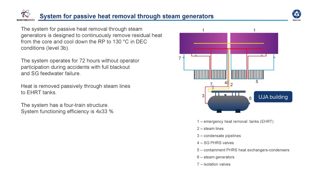
System for passive heat removal through steam generatorsThe system for passive heat removal through steam
generators is designed to continuously remove residual heat
from the core and cool down the RP to 130 °C in DEC
conditions (level 3b).
The system operates for 72 hours without operator
participation during accidents with full blackout
and SG feedwater failure.
Heat is removed passively through steam lines
to EHRT tanks.
1
1
7
7
5
4 2
3
6
UJA building
The system has a four-train structure.
System functioning efficiency is 4x33 %
1 – emergency heat removal tanks (EHRT)
2 – steam lines
3 – condensate pipelines
4 – SG PHRS valves
5 – containment PHRS heat exchangers-condensers
6 – steam generators
7 – isolation valves
30.
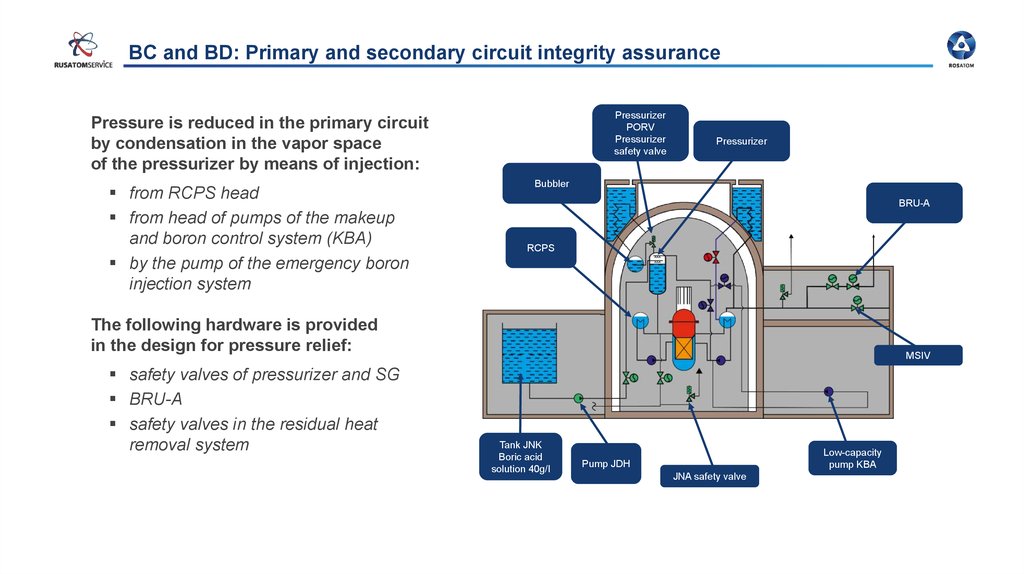
BC and BD: Primary and secondary circuit integrity assurancePressurizer
PORV
Pressurizer
safety valve
Pressure is reduced in the primary circuit
by condensation in the vapor space
of the pressurizer by means of injection:
from RCPS head
from head of pumps of the makeup
and boron control system (KBA)
by the pump of the emergency boron
injection system
Pressurizer
Bubbler
BRU-A
RCPS
The following hardware is provided
in the design for pressure relief:
safety valves of pressurizer and SG
BRU-A
safety valves in the residual heat
removal system
MSIV
Tank JNK
Boric acid
solution 40g/l
Low-capacity
pump KBA
Pump JDH
JNA safety valve
31.
Pressurizer relief devicesThe primary circuit overpressure protection system includes three pilot-operated relief valves,
each consisting of the following:
main valve
relief valves with pipelines
cutoff valve
spring setting valve
additional control line with three successive valves
PORV 1 control – actuation pressure: 18.11 MPa.
PORV2, PORV3 operating – actuation pressure: 18.6 MPa.
Steam is discharged into bubbler JEG
32.
BE: Spent fuel coolingThe following systems are provided for in the design to remove heat from spent fuel
assemblies stored in the spent fuel pool:
Fuel pool cooling system (FAK)
JMN/JNG/JNA system
For maintaining water level in the spent fuel pool:
FAK system pumps
FAL system pumps
KBB system pumps
JMN system pumps
Pump FAK
Heat exchanger FAK
Pump KBB
Pump KAA
Pump FAL
Heat exchanger KAA
Pump of the service water
system for essential
consumers
Heat exchanger JNG1
Pump JMN
Sump tank JNK
Spent fuel pool FAK
33.
Rosatom State Atomic Energy CorporationC. Localization of activity
34.
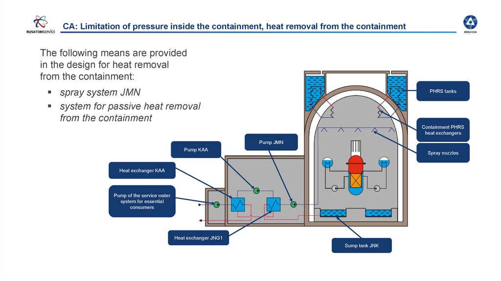
CA: Limitation of pressure inside the containment, heat removal from the containmentThe following means are provided
in the design for heat removal
from the containment:
spray system JMN
system for passive heat removal
from the containment
PHRS tanks
Containment PHRS
heat exchangers
Pump JMN
Pump KAA
Spray nozzles
Heat exchanger KAA
Pump of the service water
system for essential
consumers
Heat exchanger JNG1
Sump tank JNK
35.
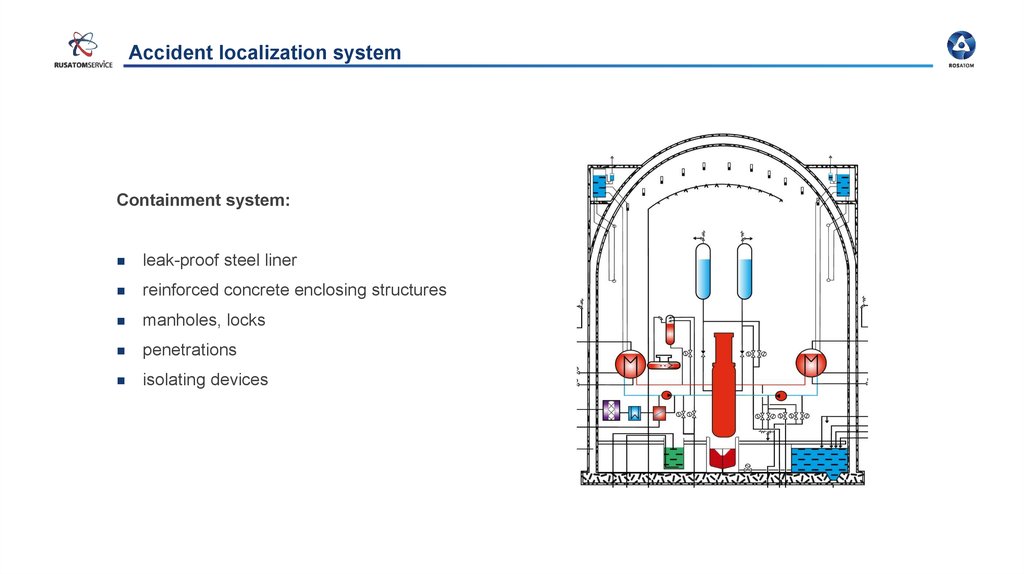
Accident localization systemContainment system:
leak-proof steel liner
reinforced concrete enclosing structures
manholes, locks
penetrations
isolating devices
36.
AES-2006/E LayoutReactor building
Steam cell
Safety building
Standby diesel generator
station building