Похожие презентации:
Agenda. Overview of Diagnosis
1. Agenda
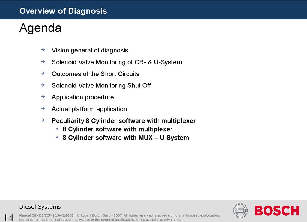
Overview of DiagnosisAgenda
Vision general of diagnosis
Solenoid Valve Monitoring of CR- & U-System
Outcomes of the Short Circuits
Solenoid Valve Monitoring Shut Off
Application procedure
Actual platform application
Peculiarity 8 Cylinder software with multiplexer
Diesel Systems
1
Manuel Gil - DS/ECP4| 15/03/2008 | © Robert Bosch GmbH 2007. All rights reserved, also regarding any disposal, exploitation,
reproduction, editing, distribution, as well as in the event of applications for industrial property rights.
2. Agenda
Overview of DiagnosisAgenda
Vision general of diagnosis
Functional diagnosis requirements
Diagnosis requirements
Overview of detectable errors by diagnosis
Solenoid Valve Monitoring of CR- & U-System
Outcomes of the Short Circuits
Solenoid Valve Monitoring Shut Off
Application procedure
Actual platform application
Peculiarity 8 Cylinder software with multiplexer
Diesel Systems
2
Manuel Gil - DS/ECP4| 15/03/2008 | © Robert Bosch GmbH 2007. All rights reserved, also regarding any disposal, exploitation,
reproduction, editing, distribution, as well as in the event of applications for industrial property rights.
3. Functional Diagnosis Requirements
Overview of DiagnosisFunctional Diagnosis Requirements
The objective of injector diagnosis is the detection and classification of errors which
can occur while supplying current to an injector as well as the introduction of a desired
substitute reaction in the error characteristic.
Personal protection: Prevention of missed injections or wrong injection quantity
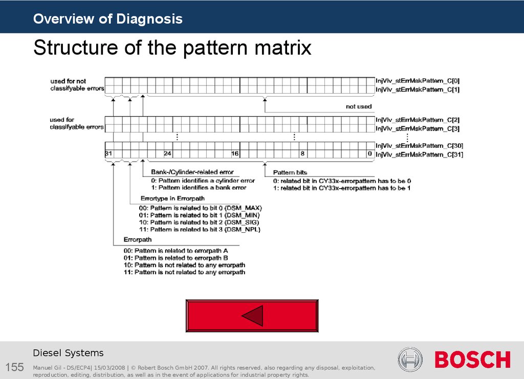
which can generate undesired engine torque. Occurrence of such errors must always
lead to immediate injection Shut Off.
Engine and component protection: Prevention of missed injections or wrong
injection quantity, which can damage the engine during combustion. In this case the
Common Rail System is significantly more critical than the UI System. This is because
in the rail, a sufficiently high diesel pressure is always available for the injectors at any
point of time.
Availability: Ensuring the maximum possible availability in the case of an error
through defined bank Shut Off or cylinder Shut Off.
Exhaust gas: Prevention of an uncontrolled increase in the emission of toxic
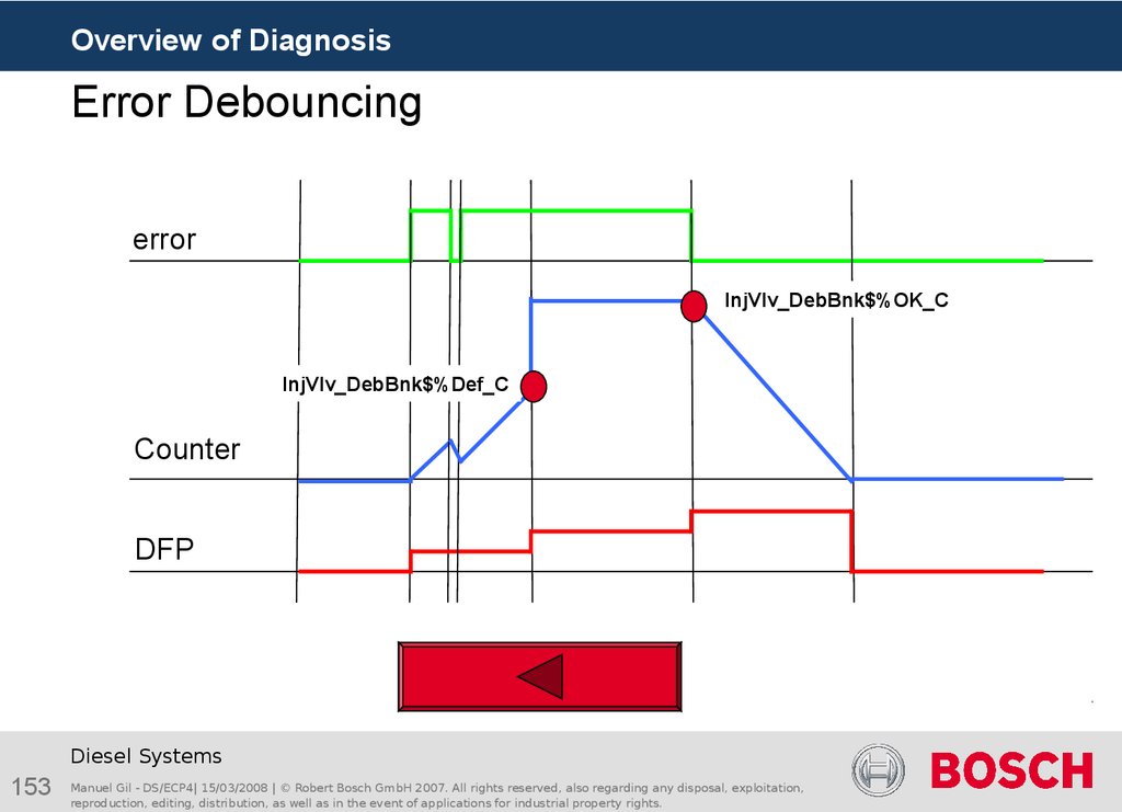
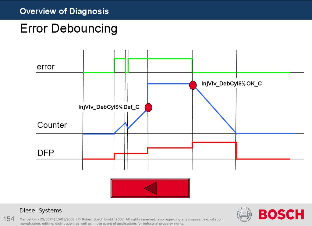
substances.
OBD: Supply the ECU-diagnosis management with information about injector
diagnosis status to fulfill OBD legislation.
Service: Providing error information, as detailed as possible, for service in order to
ensure efficient and cost- effective repair.
Diesel Systems
3
Manuel Gil - DS/ECP4| 15/03/2008 | © Robert Bosch GmbH 2007. All rights reserved, also regarding any disposal, exploitation,
reproduction, editing, distribution, as well as in the event of applications for industrial property rights.
4. Diagnosis Requirements
Overview of DiagnosisDiagnosis Requirements
Robust diagnosis – Reaction to every error: Even in the case of an error which
occurs but cannot be classified as a known error, a detection has to be always carried
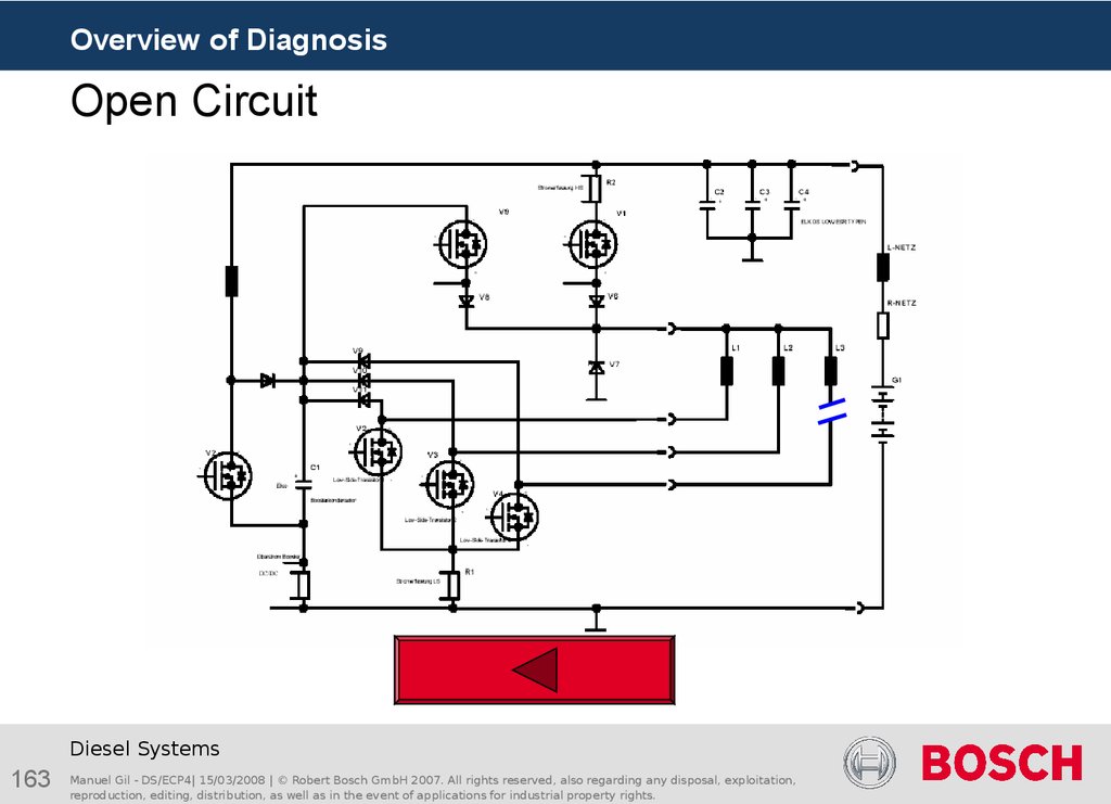
out and it has to be at least classified as unknown bank/cylinder error. As a result, the
applied error reaction is then activated and a dangerous situation can be avoided
No detection of inexistence errors
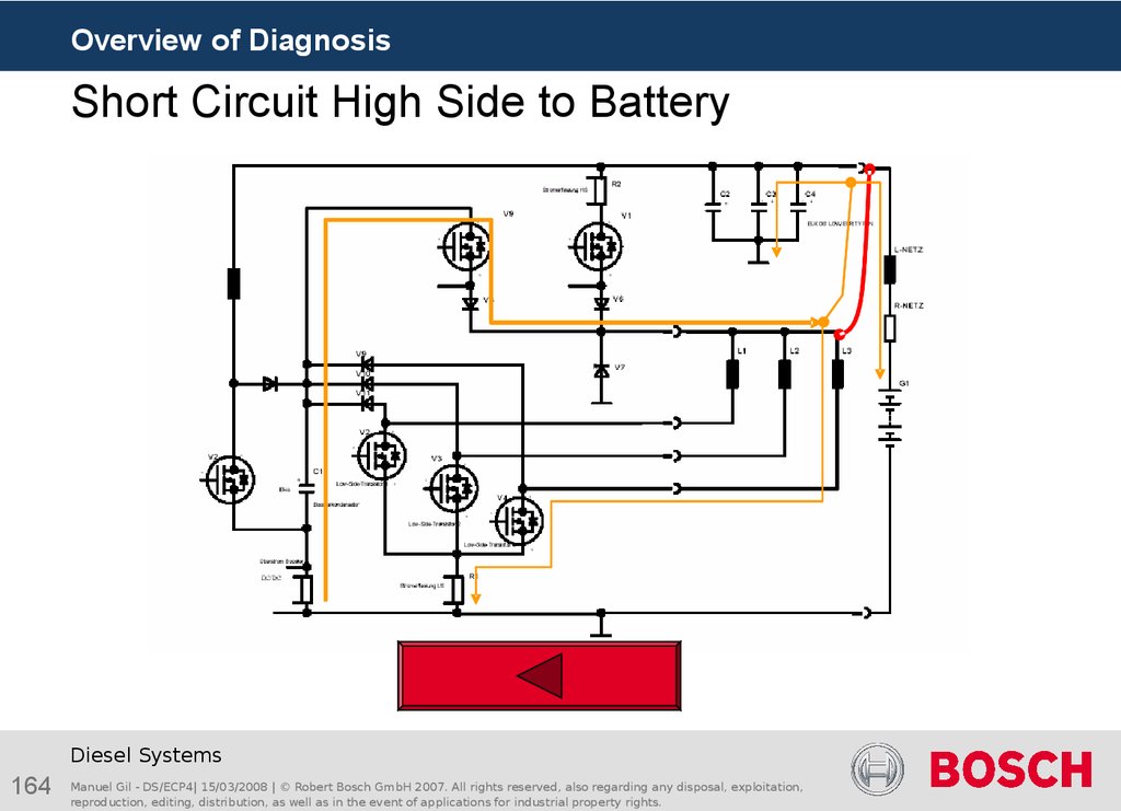
Applicable Cylinder Shut Off
Applicable Bank Shut Off
Applicable Test Injections
Diesel Systems
4
Manuel Gil - DS/ECP4| 15/03/2008 | © Robert Bosch GmbH 2007. All rights reserved, also regarding any disposal, exploitation,
reproduction, editing, distribution, as well as in the event of applications for industrial property rights.
5. Overview of detectable errors by diagnosis (1)
Overview of DiagnosisOverview of detectable errors by diagnosis (1)
Ubatt
- Open Circuit (OC)
- Short Circuit Coil (SCHSLS)
- Short Circuit High Side to Battery (SCHSBA)
OC
- Short Circuit High Side to Ground (SCHSGN)
- Short Circuit Low Side to Battery (SCLSBA)
- Short Circuit Low Side to Ground (SCLSGN)
Gnd
Diesel Systems
5
Manuel Gil - DS/ECP4| 15/03/2008 | © Robert Bosch GmbH 2007. All rights reserved, also regarding any disposal, exploitation,
reproduction, editing, distribution, as well as in the event of applications for industrial property rights.
6. Overview of detectable errors by diagnosis (2)
Overview of DiagnosisOverview of detectable errors by diagnosis (2)
Ubatt
- Open Circuit (OC)
- Short Circuit Coil (SCHSLS)
SCHSLS
- Short Circuit High Side to Battery (SCHSBA)
- Short Circuit High Side to Ground (SCHSGN)
- Short Circuit Low Side to Battery (SCLSBA)
- Short Circuit Low Side to Ground (SCLSGN)
Gnd
Diesel Systems
6
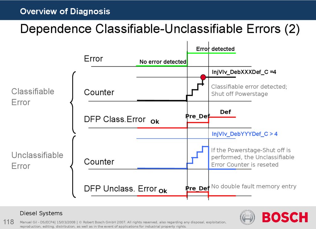
Manuel Gil - DS/ECP4| 15/03/2008 | © Robert Bosch GmbH 2007. All rights reserved, also regarding any disposal, exploitation,
reproduction, editing, distribution, as well as in the event of applications for industrial property rights.
7. Overview of detectable errors by diagnosis (3)
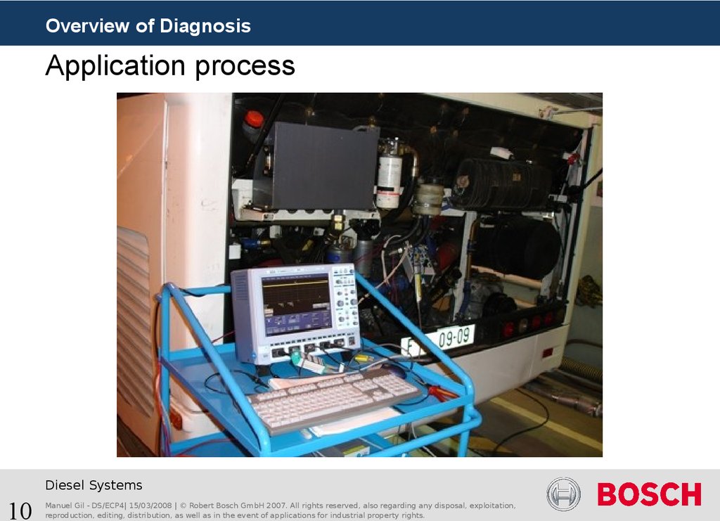
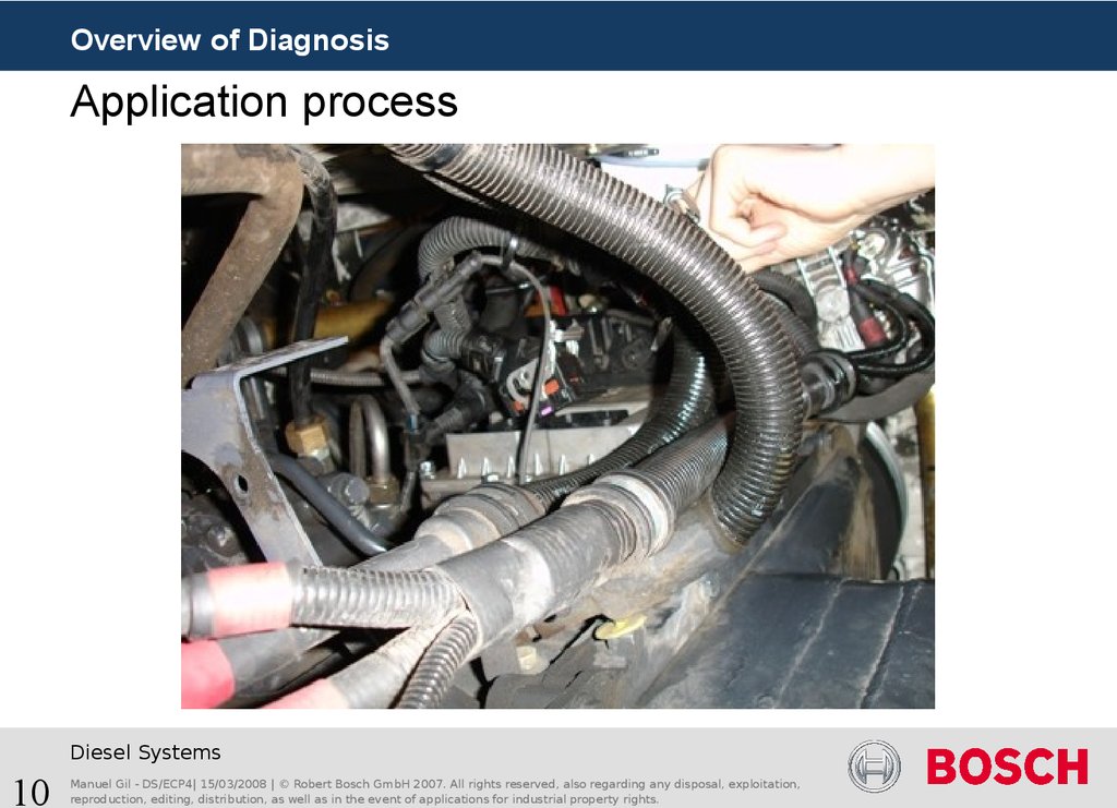
Overview of DiagnosisOverview of detectable errors by diagnosis (3)
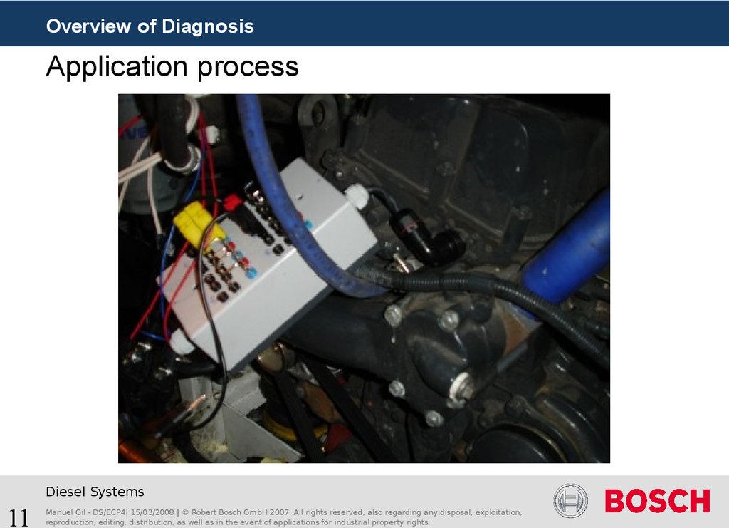
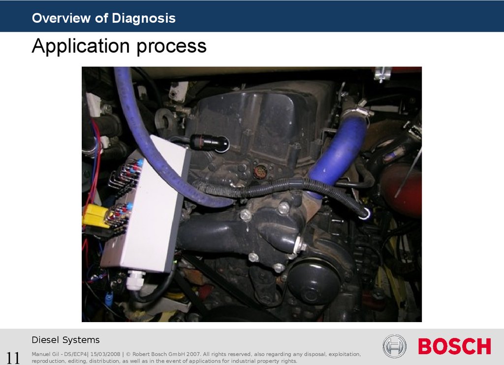
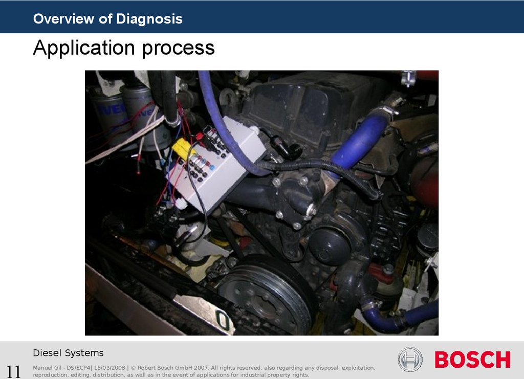
Ubatt
- Open Circuit (OC)
- Short Circuit Coil (SCHSLS)
SCHSBA
- Short Circuit High Side to Battery (SCHSBA)
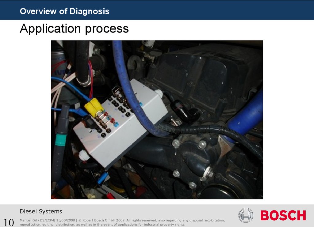
- Short Circuit High Side to Ground (SCHSGN)
- Short Circuit Low Side to Battery (SCLSBA)
- Short Circuit Low Side to Ground (SCLSGN)
Gnd
Diesel Systems
7
Manuel Gil - DS/ECP4| 15/03/2008 | © Robert Bosch GmbH 2007. All rights reserved, also regarding any disposal, exploitation,
reproduction, editing, distribution, as well as in the event of applications for industrial property rights.
8. Overview of detectable errors by diagnosis (4)
Overview of DiagnosisOverview of detectable errors by diagnosis (4)
Ubatt
- Open Circuit (OC)
- Short Circuit Coil (SCHSLS)
- Short Circuit High Side to Battery (SCHSBA)
- Short Circuit High Side to Ground (SCHSGN)
- Short Circuit Low Side to Battery (SCLSBA)
- Short Circuit Low Side to Ground (SCLSGN)
SCHSGN
Gnd
Diesel Systems
8
Manuel Gil - DS/ECP4| 15/03/2008 | © Robert Bosch GmbH 2007. All rights reserved, also regarding any disposal, exploitation,
reproduction, editing, distribution, as well as in the event of applications for industrial property rights.
9. Overview of detectable errors by diagnosis (5)
Overview of DiagnosisOverview of detectable errors by diagnosis (5)
Ubatt
- Open Circuit (OC)
- Short Circuit Coil (SCHSLS)
SCLSBA
- Short Circuit High Side to Battery (SCHSBA)
- Short Circuit High Side to Ground (SCHSGN)
- Short Circuit Low Side to Battery (SCLSBA)
- Short Circuit Low Side to Ground (SCLSGN)
Gnd
Diesel Systems
9
Manuel Gil - DS/ECP4| 15/03/2008 | © Robert Bosch GmbH 2007. All rights reserved, also regarding any disposal, exploitation,
reproduction, editing, distribution, as well as in the event of applications for industrial property rights.
10. Overview of detectable errors by diagnosis (6)
Overview of DiagnosisOverview of detectable errors by diagnosis (6)
Ubatt
- Open Circuit (OC)
- Short Circuit Coil (SCHSLS)
- Short Circuit High Side to Battery (SCHSBA)
- Short Circuit High Side to Ground (SCHSGN)
- Short Circuit Low Side to Battery (SCLSBA)
- Short Circuit Low Side to Ground (SCLSGN)
SCLSGN
Gnd
Diesel Systems
10
Manuel Gil - DS/ECP4| 15/03/2008 | © Robert Bosch GmbH 2007. All rights reserved, also regarding any disposal, exploitation,
reproduction, editing, distribution, as well as in the event of applications for industrial property rights.
11. Agenda
Overview of DiagnosisAgenda
Vision general of diagnosis
Solenoid Valve Monitoring of CR- & U-System
Scheduling of the diagnosis
Monitoring Overview (InjVlv_Mon)
Error messages transferred via SPI
Error Pattern
Pattern recognition sequence
Error Debouncing
InjVlv_Mon Labels
Peculiarity for CV-System
Outcomes of the Short Circuits
Solenoid Valve Monitoring Shut Off
Application procedure
Actual platform application
Peculiarity 8 Cylinder software with multiplexer
Diesel Systems
11
Manuel Gil - DS/ECP4| 15/03/2008 | © Robert Bosch GmbH 2007. All rights reserved, also regarding any disposal, exploitation,
reproduction, editing, distribution, as well as in the event of applications for industrial property rights.
12. Scheduling of the diagnosis
Overview of DiagnosisScheduling of the diagnosis
The injector energizing diagnostic function is performed once for each completed motor
cycle (each 720° crankshaft ). After a completed motor cycle all necessary diagnostic
information are available.
Example for 6 Cylinders, 2 Bank System
Cyl1
Cyl5
Cyl3
Cyl6
Cyl2
Cyl4
Cyl1
Cyl5
B1
B2
B1
B2
B1
B2
B1
B2
Read SPI Info
from Chip
Injector
diagnosis
Diesel Systems
12
Manuel Gil - DS/ECP4| 15/03/2008 | © Robert Bosch GmbH 2007. All rights reserved, also regarding any disposal, exploitation,
reproduction, editing, distribution, as well as in the event of applications for industrial property rights.
Injector
diagnosis
13. Monitoring Overview (InjVlv_Mon) (1)
Overview of DiagnosisMonitoring Overview (InjVlv_Mon) (1)
Pattern Matrix
CY33x-error
messages
SPI-Communication
rearrange
Select Matrix
CY33x
Pattern-
error pattern
recognition
Physical
error –
debouncing
Shut Offcoordinator
InjVlv_Mon
The error messages are transmitted from the power stage component CY33x via SPI to the
microcontroller and rearrange to calculate an error pattern.
Diesel Systems
13
Manuel Gil - DS/ECP4| 15/03/2008 | © Robert Bosch GmbH 2007. All rights reserved, also regarding any disposal, exploitation,
reproduction, editing, distribution, as well as in the event of applications for industrial property rights.
14. Monitoring Overview (InjVlv_Mon)(2)
Overview of DiagnosisMonitoring Overview (InjVlv_Mon)(2)
Pattern Matrix
CY33x-error
messages
SPI-Communication
rearrange
Select Matrix
CY33x
Pattern-
error pattern
recognition
Physical
error –
debouncing
Shut Offcoordinator
InjVlv_Mon
The error pattern is now subjected to a pattern recognition. Logical operations are performed
on pattern and select matrix entries to check whether the error pattern matches one of the
known physical errors.
Diesel Systems
14
Manuel Gil - DS/ECP4| 15/03/2008 | © Robert Bosch GmbH 2007. All rights reserved, also regarding any disposal, exploitation,
reproduction, editing, distribution, as well as in the event of applications for industrial property rights.
15. Monitoring Overview (InjVlv_Mon) (3)
Overview of DiagnosisMonitoring Overview (InjVlv_Mon) (3)
Pattern Matrix
CY33x-error
messages
SPI-Communication
rearrange
Select Matrix
CY33x
Pattern-
error pattern
recognition
Physical
error –
debouncing
Shut Offcoordinator
InjVlv_Mon
If an error pattern is identified and classified, the system is Shut Off depending on the severity
of the error.
Diesel Systems
15
Manuel Gil - DS/ECP4| 15/03/2008 | © Robert Bosch GmbH 2007. All rights reserved, also regarding any disposal, exploitation,
reproduction, editing, distribution, as well as in the event of applications for industrial property rights.
16. Error messages transferred via SPI (1)
Overview of DiagnosisError messages transferred via SPI (1)
Example for 6 Cylinders, 2 Bank System
Pattern Matrix
Select Matrix
CY33x-error
messages
SPI-Communication
6 Cyl specific Error
rearrange
CY33x
Pattern-
error pattern
recognition
Physical
error –
debouncing
2 Bank specific Error
InjVlv_Mon
Diesel Systems
16
Manuel Gil - DS/ECP4| 15/03/2008 | © Robert Bosch GmbH 2007. All rights reserved, also regarding any disposal, exploitation,
reproduction, editing, distribution, as well as in the event of applications for industrial property rights.
Shut Offcoordinator
17. Folie 17
Overview of DiagnosisError messages transferred via SPI (2)
Structure of an internal CY33x cylinder error register
This information is displayed in the measuring point: InjVlv_stErrCyl$_mp
InjVlv_stErrCyl$_mp.Bit0…7
= 1 -> The event took place
= 0 -> Default value
Diesel Systems
17
Manuel Gil - DS/ECP4| 15/03/2008 | © Robert Bosch GmbH 2007. All rights reserved, also regarding any disposal, exploitation,
reproduction, editing, distribution, as well as in the event of applications for industrial property rights.
18. Folie 18
Overview of DiagnosisError messages transferred via SPI (3)
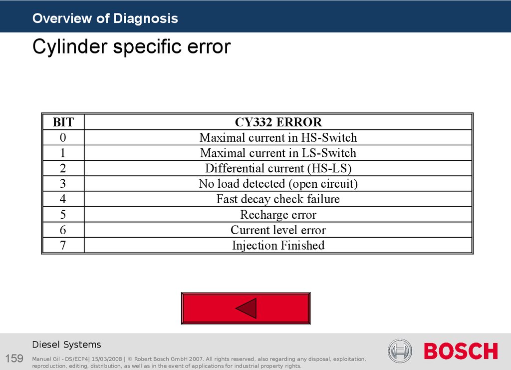
InjVlv_stErrCyl$_mp.Bit0 - Maximal current in HS-Switch
I
InjVlv_iThresMax_C
t
Boosterphase
InjVlv_iThresMax_C (Threshold for over current detection of injection power stage) ≈ 32.2 A
Diesel Systems
18
Manuel Gil - DS/ECP4| 15/03/2008 | © Robert Bosch GmbH 2007. All rights reserved, also regarding any disposal, exploitation,
reproduction, editing, distribution, as well as in the event of applications for industrial property rights.
19. Folie 19
Overview of DiagnosisError messages transferred via SPI (4)
InjVlv_stErrCyl$_mp.Bit1 - Maximal current in LS-Switch
I
InjVlv_iThresMax_C
t
InjVlv_iThresMax_C (Threshold for over current detection of injection power stage) ≈ 32.2 A
Diesel Systems
19
Manuel Gil - DS/ECP4| 15/03/2008 | © Robert Bosch GmbH 2007. All rights reserved, also regarding any disposal, exploitation,
reproduction, editing, distribution, as well as in the event of applications for industrial property rights.
20. Error messages transferred via SPI (5)
Overview of DiagnosisError messages transferred via SPI (5)
InjVlv_stErrCyl$_mp.Bit2 - Differential current (HS-LS)
I1 + I 2
I1
I2
InjVlv_stRegDmsk_C - To configure which current level should be use to detect a current
difference between HS and LS
Diesel Systems
20
Manuel Gil - DS/ECP4| 15/03/2008 | © Robert Bosch GmbH 2007. All rights reserved, also regarding any disposal, exploitation,
reproduction, editing, distribution, as well as in the event of applications for industrial property rights.
21. Error messages transferred via SPI (6)
Overview of DiagnosisError messages transferred via SPI (6)
InjVlv_stErrCyl$_mp.Bit3 - No load detected (open circuit)
Imin = Umin / (Rs x (RR/Rv)) = 2,66 A
I
2,6 A
Check for I > 2.6
A
The current in HS-Shunt and LS-Shunt must exceed Imin level during energizing time
Diesel Systems
21
Manuel Gil - DS/ECP4| 15/03/2008 | © Robert Bosch GmbH 2007. All rights reserved, also regarding any disposal, exploitation,
reproduction, editing, distribution, as well as in the event of applications for industrial property rights.
t
22. Error messages transferred via SPI (7)
Overview of DiagnosisError messages transferred via SPI (7)
InjVlv_stErrCyl$_mp.Bit4 – Fast decay check failure (C-System)
InjVlv_stTiCy330Dec_C (8μs)
I
LS-ON
t
InjCrv_tiElecPse_C (100μs)
InjVlv_stTiDelAftFastIDec_C – Time limit for measuring duration of fast decay
InjVlv_stTiFastIDecErrMax_C – Max. allowed time for fast current decay
Diesel Systems
22
Manuel Gil - DS/ECP4| 15/03/2008 | © Robert Bosch GmbH 2007. All rights reserved, also regarding any disposal, exploitation,
reproduction, editing, distribution, as well as in the event of applications for industrial property rights.
23. Error messages transferred via SPI(8)
Overview of DiagnosisError messages transferred via SPI(8)
InjVlv_stErrCyl$_mp.Bit4 – Fast decay check failure (C-System)
InjVlv_stTiDelAftFastIDec_C
I
LS-ON
t
InjVlv_stTiFastIDecErrMax_C
Diesel Systems
23
Manuel Gil - DS/ECP4| 15/03/2008 | © Robert Bosch GmbH 2007. All rights reserved, also regarding any disposal, exploitation,
reproduction, editing, distribution, as well as in the event of applications for industrial property rights.
24. Error messages transferred via SPI (9)
Overview of DiagnosisError messages transferred via SPI (9)
InjVlv_stErrCyl$_mp.Bit6 – Current Level Error
Low
Battery
I
t
False wiring
harness
SCLSGN
Diesel Systems
24
Manuel Gil - DS/ECP4| 15/03/2008 | © Robert Bosch GmbH 2007. All rights reserved, also regarding any disposal, exploitation,
reproduction, editing, distribution, as well as in the event of applications for industrial property rights.
25. Error messages transferred via SPI (10)
Overview of DiagnosisError messages transferred via SPI (10)
InjVlv_stErrCyl$_mp.Bit7 – Injection Finished
ON Signal
Information that CY33x internal state machine (without any error) performed a
complete energizing cycle.
This Bit can only be set if FastDecayCheck feature is enabled. The injection finished bit
is set when the pre-instruction FastDecayCheck is finished.
Diesel Systems
25
Manuel Gil - DS/ECP4| 15/03/2008 | © Robert Bosch GmbH 2007. All rights reserved, also regarding any disposal, exploitation,
reproduction, editing, distribution, as well as in the event of applications for industrial property rights.
26. Error messages transferred via SPI (11)
Overview of DiagnosisError messages transferred via SPI (11)
Structure of an internal CY33x bank error register
This information is displayed in the measuring point: InjVlv_stErrBnk$_mp
InjVlv_stErrBnk$_mp.Bit0…7 = 1 -> The event took place
= 0 -> Default value
Diesel Systems
26
Manuel Gil - DS/ECP4| 15/03/2008 | © Robert Bosch GmbH 2007. All rights reserved, also regarding any disposal, exploitation,
reproduction, editing, distribution, as well as in the event of applications for industrial property rights.
27. Error messages transferred via SPI (12)
Overview of DiagnosisError messages transferred via SPI (12)
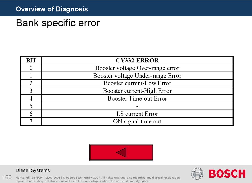
InjVlv_stErrBnk$_mp.Bit0 - Booster voltage Over-range error
CY33x
InjVlv_uCMax_C (Threshold for booster over voltage of injector power stage) ≈ 61,9 V
Diesel Systems
27
Manuel Gil - DS/ECP4| 15/03/2008 | © Robert Bosch GmbH 2007. All rights reserved, also regarding any disposal, exploitation,
reproduction, editing, distribution, as well as in the event of applications for industrial property rights.
28. Error messages transferred via SPI (13)
Overview of DiagnosisError messages transferred via SPI (13)
InjVlv_stErrBnk$_mp.Bit1 - Booster voltage Under-range error
CY33x
InjVlv_uCMin_C (Booster voltage low indicator of injection power stage) ≈ 35-42 V
Diesel Systems
28
Manuel Gil - DS/ECP4| 15/03/2008 | © Robert Bosch GmbH 2007. All rights reserved, also regarding any disposal, exploitation,
reproduction, editing, distribution, as well as in the event of applications for industrial property rights.
29. Error messages transferred via SPI (14)
Overview of DiagnosisError messages transferred via SPI (14)
InjVlv_stErrBnk$_mp.Bit2 - Booster current-Low Error
Check for I > 2.6
A
InjVlv_stTiBstErrMin_C
InjVlv_stTiBstErrMin_C (I must exceed Imin level after this time) ≈ 64 µs
Diesel Systems
29
Manuel Gil - DS/ECP4| 15/03/2008 | © Robert Bosch GmbH 2007. All rights reserved, also regarding any disposal, exploitation,
reproduction, editing, distribution, as well as in the event of applications for industrial property rights.
30. Error messages transferred via SPI (15)
Overview of DiagnosisError messages transferred via SPI (15)
InjVlv_stErrBnk$_mp.Bit3 - Booster current-High Error
Applied to 66.6 A at EDC7UC31 (bigger than overlapping injections 2 x 25 A)
Diesel Systems
30
Manuel Gil - DS/ECP4| 15/03/2008 | © Robert Bosch GmbH 2007. All rights reserved, also regarding any disposal, exploitation,
reproduction, editing, distribution, as well as in the event of applications for industrial property rights.
31. Error messages transferred via SPI (16)
Overview of DiagnosisError messages transferred via SPI (16)
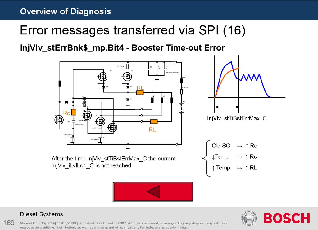
InjVlv_stErrBnk$_mp.Bit4 - Booster Time-out Error
RL
Rc
InjVlv_stTiBstErrMax_C
RL
After the time InjVlv_stTiBstErrMax_C the current
InjVlv_iLvlLo1_C is not reached.
Old SG
↑ Rc
↓Temp
↑ Rc
↑ Temp
↑ RL
Diesel Systems
31
Manuel Gil - DS/ECP4| 15/03/2008 | © Robert Bosch GmbH 2007. All rights reserved, also regarding any disposal, exploitation,
reproduction, editing, distribution, as well as in the event of applications for industrial property rights.
32. Error messages transferred via SPI (17)
Overview of DiagnosisError messages transferred via SPI (17)
InjVlv_stErrBnk$_mp.Bit6 – LS current Error
I
LS-ON
t
Check for I > 2.6
A
Diesel Systems
32
Manuel Gil - DS/ECP4| 15/03/2008 | © Robert Bosch GmbH 2007. All rights reserved, also regarding any disposal, exploitation,
reproduction, editing, distribution, as well as in the event of applications for industrial property rights.
33. Error messages transferred via SPI (18)
Overview of DiagnosisError messages transferred via SPI (18)
InjVlv_stErrBnk$_mp.Bit7 – ON Signal time out
ON Signal
InjVlv_tiTiInjMax_C
InjVlv_tiTiInjMax_C (Max. allowed time for active ON-signal)
Diesel Systems
33
Manuel Gil - DS/ECP4| 15/03/2008 | © Robert Bosch GmbH 2007. All rights reserved, also regarding any disposal, exploitation,
reproduction, editing, distribution, as well as in the event of applications for industrial property rights.
34. Error pattern (1)
Overview of DiagnosisError pattern (1)
Pattern Matrix
CY332-error
messages
SPI-Communication
rearrange
Select Matrix
CY332
Pattern-
error pattern
recognition
Physical
error –
debouncing
InjVlv_Mon
Diesel Systems
34
Manuel Gil - DS/ECP4| 15/03/2008 | © Robert Bosch GmbH 2007. All rights reserved, also regarding any disposal, exploitation,
reproduction, editing, distribution, as well as in the event of applications for industrial property rights.
Shut Offcoordinator
35. Folie 35
Overview of DiagnosisError pattern (2)
A CY33x error pattern is rearranged for each cylinder.
The following figure shows this arrangement for cylinder 1.in a 2 Bank system (Cylinders
1, 2 and 3 in Bank 1)
3
Diesel Systems
35
Manuel Gil - DS/ECP4| 15/03/2008 | © Robert Bosch GmbH 2007. All rights reserved, also regarding any disposal, exploitation,
reproduction, editing, distribution, as well as in the event of applications for industrial property rights.
36. Pattern recognition sequence (1)
Overview of DiagnosisPattern recognition sequence (1)
Pattern Matrix
CY332-error
messages
SPI-Communication
rearrange
Select Matrix
CY332
Pattern-
error pattern
recognition
Physical
error –
debouncing
InjVlv_Mon
Diesel Systems
36
Manuel Gil - DS/ECP4| 15/03/2008 | © Robert Bosch GmbH 2007. All rights reserved, also regarding any disposal, exploitation,
reproduction, editing, distribution, as well as in the event of applications for industrial property rights.
Shut Offcoordinator
37. Structure of the pattern matrix
Overview of DiagnosisPattern recognition sequence (2)
Structure of the pattern matrix
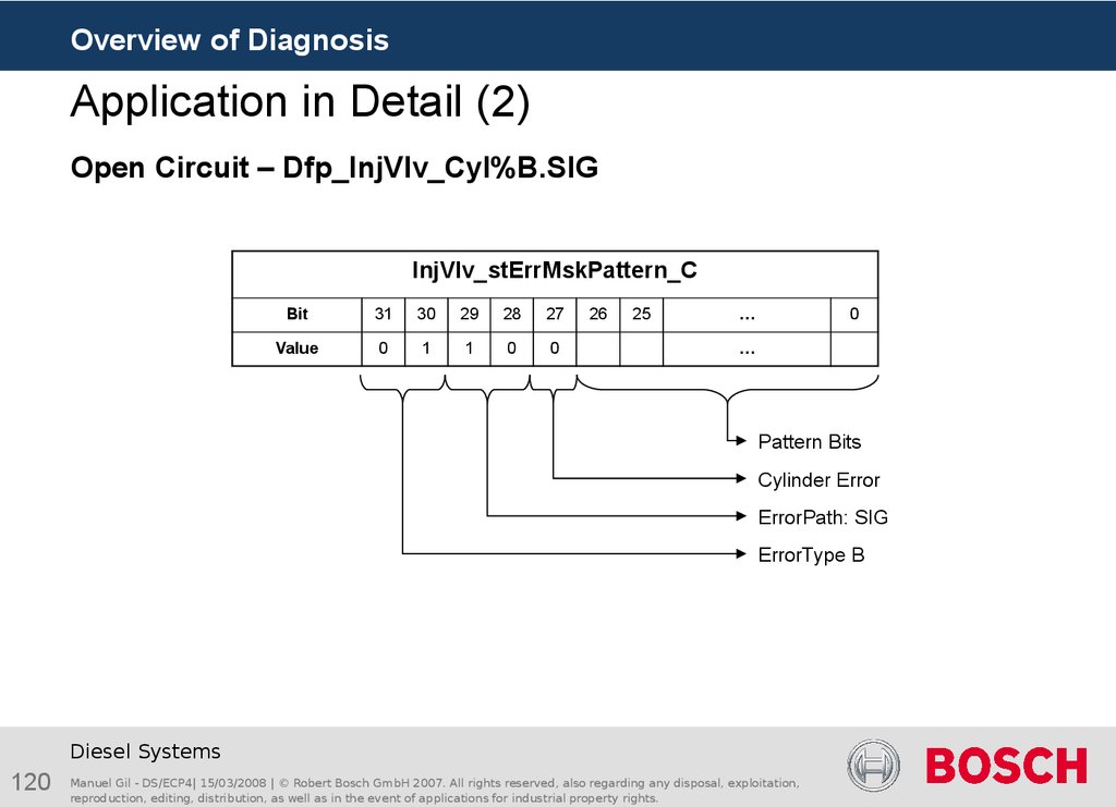
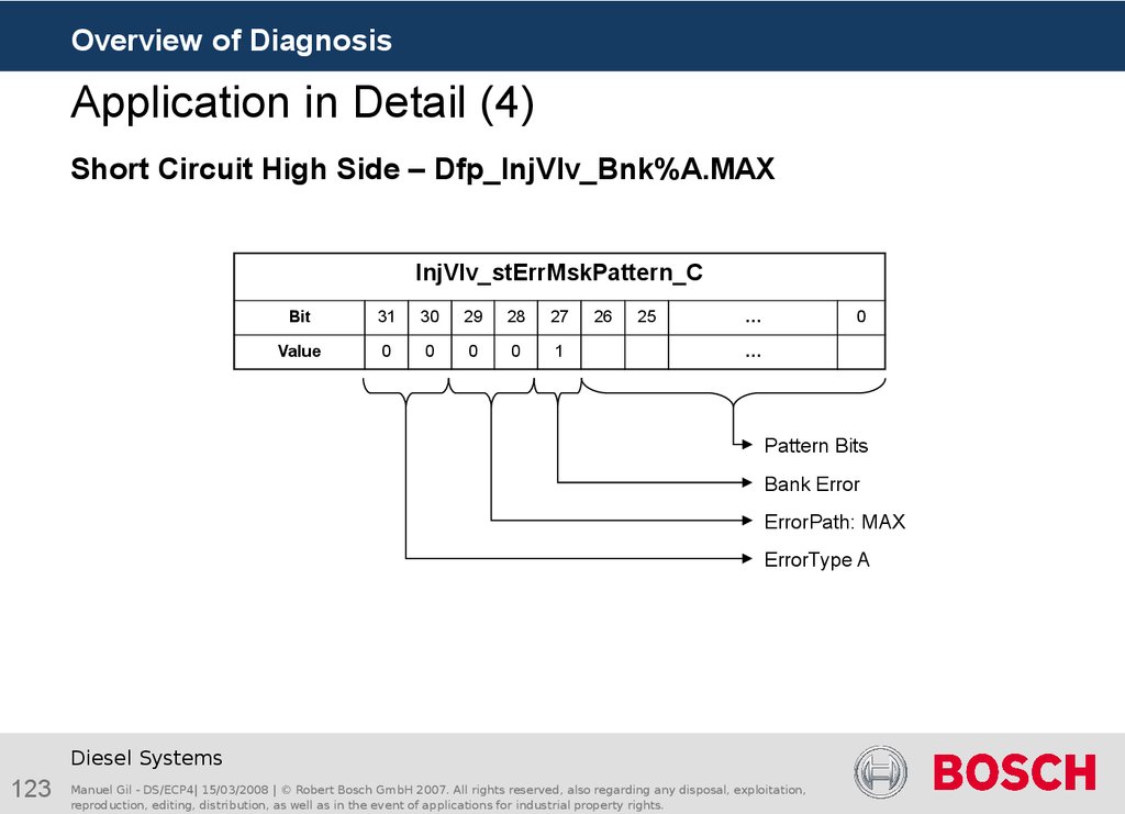
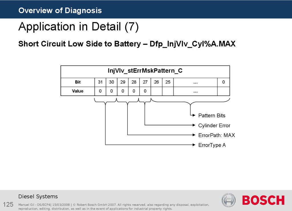
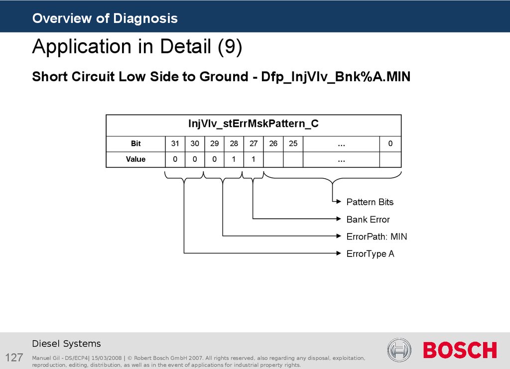
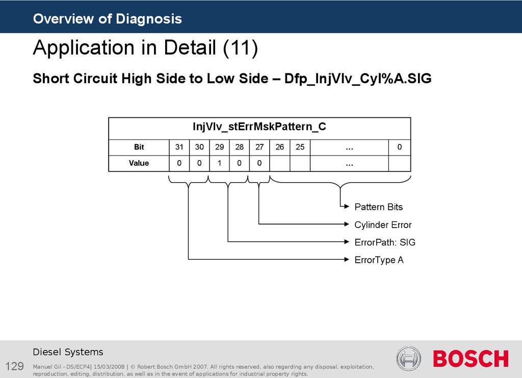
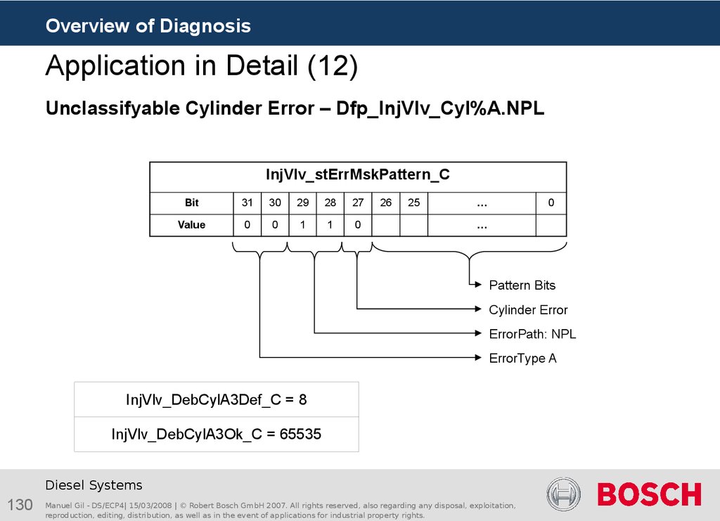
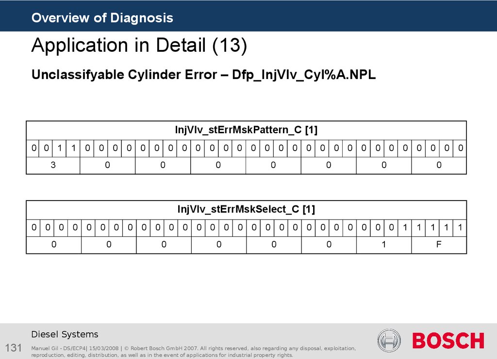
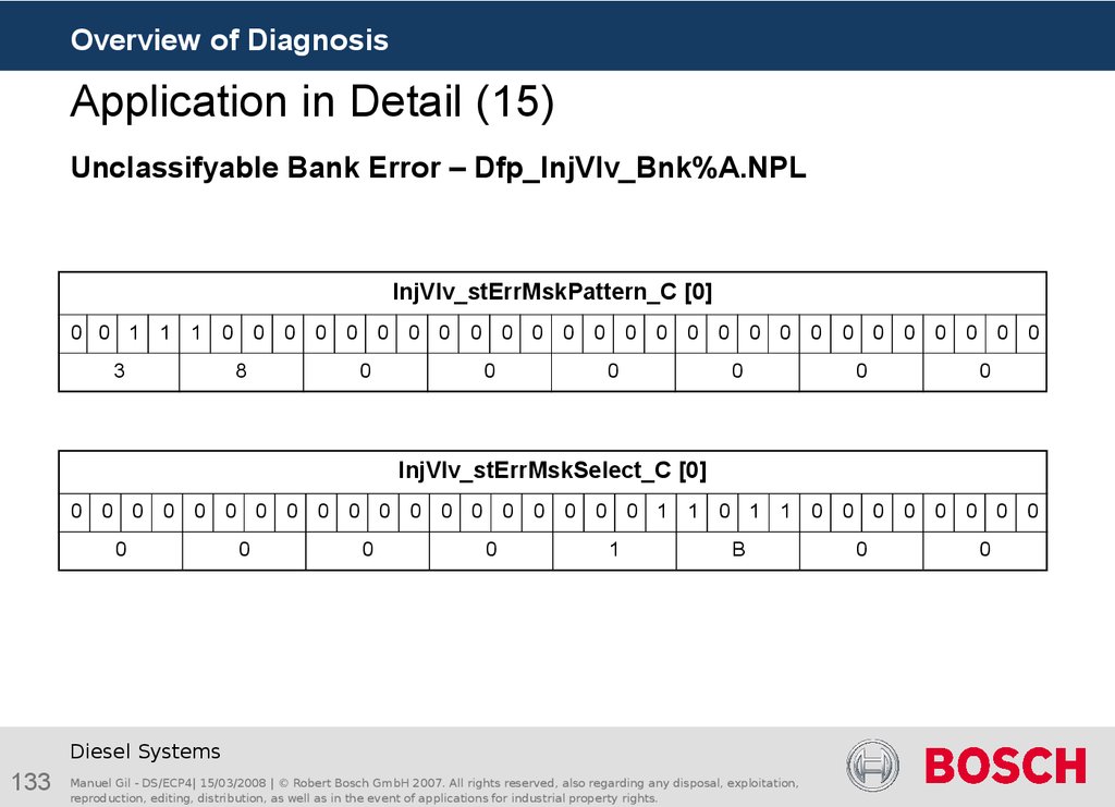
The pattern matrix InjVlv_stErrMskPattern_C is composed of 32 entries which are
each 32 bits wide.
Error patterns which result from physical errors in the injector cables can be applied by
the pattern matrix. An entry in the matrix describes a pattern of a physical error.
The allocation of bits 0 to 26 to individual matrix entries refers to the same bits in the
CY33x error pattern (described in the Error pattern).
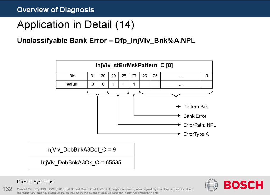
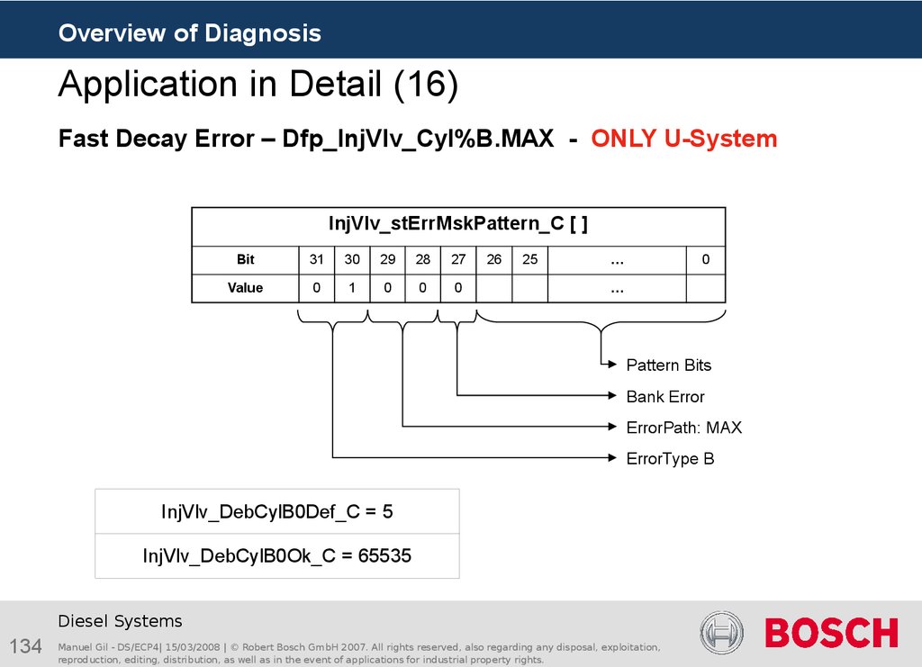
The most significant bits in each matrix entry indicate the physical error to which the
pattern belongs. Bit 27 indicates whether the pattern identifies a bank error or a
cylinder error. Bits 28 and 29 determine the error type and the error bit for the error
path. Bits 30 and 31 determine which of both bank and cylinder error paths (A or B) is
allocated to this pattern entry.
Entries 0 and 1 are used for errors that cannot be classified. Entries 2 to 31 can be
used for errors that can be classified.
Since entries 0 and 1 are used for unclassified errors, bits 0 to 26 are applied to 0.
Diesel Systems
37
Manuel Gil - DS/ECP4| 15/03/2008 | © Robert Bosch GmbH 2007. All rights reserved, also regarding any disposal, exploitation,
reproduction, editing, distribution, as well as in the event of applications for industrial property rights.
38. Structure of the pattern matrix
Overview of DiagnosisPattern recognition sequence (3)
Structure of the pattern matrix
Diesel Systems
38
Manuel Gil - DS/ECP4| 15/03/2008 | © Robert Bosch GmbH 2007. All rights reserved, also regarding any disposal, exploitation,
reproduction, editing, distribution, as well as in the event of applications for industrial property rights.
39. Structure of the select matrix
Overview of DiagnosisPattern recognition sequence (4)
Structure of the select matrix
The select matrix InjVlv_stErrMskSelect_C is composed of 32 entries, each 32 bits
wide.
Each entry of this matrix corresponds to the entry bearing the same number in the
pattern matrix.
The select matrix entries determine which CY33x error pattern bit is significant for the
recognition of the physical error currently under consideration. A 1 means that the
corresponding bit of the component error pattern is used for pattern recognition
and viceversa. A 0 means that the corresponding bit of the pattern is not relevant for
this physical error.
Bits 27 to 31 are not used.
Same as the pattern matrix, entries 0 and 1 handle errors which cannot be classified.
Diesel Systems
39
Manuel Gil - DS/ECP4| 15/03/2008 | © Robert Bosch GmbH 2007. All rights reserved, also regarding any disposal, exploitation,
reproduction, editing, distribution, as well as in the event of applications for industrial property rights.
40. Structure of the select matrix
Overview of DiagnosisPattern recognition sequence (5)
Structure of the select matrix
Diesel Systems
40
Manuel Gil - DS/ECP4| 15/03/2008 | © Robert Bosch GmbH 2007. All rights reserved, also regarding any disposal, exploitation,
reproduction, editing, distribution, as well as in the event of applications for industrial property rights.
41. Pattern recognition sequence (6)
Overview of DiagnosisPattern recognition sequence (6)
First, the CY33x error pattern of each cylinder is bitwise X-ored (Exclusive-Or
operation) with the pattern matrix. The result now contains a 0 for all bits which
matched in the error pattern and in the pattern matrix entry and a 1 for all the others.
Pattern Matrix [i]
1
1
1
0
0
1
0
0
Pattern Error
1
0
0
0
0
1
1
0
Pattern Matrix [i]
XOR
Pattern Error
0
1
1
0
0
0
1
0
Diesel Systems
41
Manuel Gil - DS/ECP4| 15/03/2008 | © Robert Bosch GmbH 2007. All rights reserved, also regarding any disposal, exploitation,
reproduction, editing, distribution, as well as in the event of applications for industrial property rights.
42. Pattern recognition sequence (7)
Overview of DiagnosisPattern recognition sequence (7)
The result is then connected bitwise to the relative select matrix entry (identical index)
to perform a logical AND operation. All bits which have no significance for the current
error are set to 0 and all others retain their values.
Select Matrix [i]
1
0
0
1
1
1
0
0
After XOR
0
1
1
0
1
0
1
0
Select Matrix [i]
AND
After XOR
0
0
0
0
1
0
0
0
Diesel Systems
42
Manuel Gil - DS/ECP4| 15/03/2008 | © Robert Bosch GmbH 2007. All rights reserved, also regarding any disposal, exploitation,
reproduction, editing, distribution, as well as in the event of applications for industrial property rights.
43. Pattern recognition sequence (8)
Overview of DiagnosisPattern recognition sequence (8)
If the result of the logical operation is zero, then the error (which is defined in this entry
of the pattern/select matrix) is recognized.
From entry 31 to entry 2 of the pattern and select matrices, the logical operations are
carried out. Here, several errors can be recognized.
In the measuring points InjVlv_numIdxErrCyl%_mp (% = cyl. number) the system
can display at which indices of the pattern/select matrix a match occurred. The bit
number in the measuring point InjVlv_numIdxErrCyl%_mp corresponds to the entry
number of the pattern/select matrix.
Diesel Systems
43
Manuel Gil - DS/ECP4| 15/03/2008 | © Robert Bosch GmbH 2007. All rights reserved, also regarding any disposal, exploitation,
reproduction, editing, distribution, as well as in the event of applications for industrial property rights.
44. Example of „Error identified“
Overview of DiagnosisPattern recognition sequence (9)
Example of „Error identified“
Select
Matrix [i]
1
0
0
1
1
1
0
0
Patern
Matrix [i]
1
1
1
0
0
1
0
0
Pattern
Error
1
0
0
0
0
1
1
0
XOR
0
0
0
0
=
0
ERROR
IDENTIFIED
Diesel Systems
44
Manuel Gil - DS/ECP4| 15/03/2008 | © Robert Bosch GmbH 2007. All rights reserved, also regarding any disposal, exploitation,
reproduction, editing, distribution, as well as in the event of applications for industrial property rights.
45. Example of „Error not identified“
Overview of DiagnosisPattern recognition sequence (10)
Example of „Error not identified“
Select
Matrix [h]
1
0
1
1
1
1
0
0
Patern
Matrix [h]
1
1
1
0
0
1
0
0
Pattern
Error
1
0
0
0
0
1
1
0
XOR
0
1
0
0
0
=
0
ERROR NOT
IDENTIFIED
Diesel Systems
45
Manuel Gil - DS/ECP4| 15/03/2008 | © Robert Bosch GmbH 2007. All rights reserved, also regarding any disposal, exploitation,
reproduction, editing, distribution, as well as in the event of applications for industrial property rights.
46. Example of unclassifiable error
Overview of DiagnosisPattern recognition sequence (11)
Example of unclassifiable error
Entries 0 and 1 of the pattern and select matrices are reserved for unclassifiable bank
and cylinder errors.
If no pattern of the classified errors of the pattern/select matrix matched, the error pattern
is checked for an unclassifiable error. The error pattern is compared bitwise to the relative
select matrix entry to perform a logical AND operation. If the result of the AND- operation
is zero, no error is detected.
Select
Matrix [01]
1
0
0
1
1
1
0
0
Pattern
Error
0
0
0
0
0
1
0
0
AND
0
0
0
1
UNCLASSIFIABLE ERROR IDENTIFIED
Diesel Systems
46
Manuel Gil - DS/ECP4| 15/03/2008 | © Robert Bosch GmbH 2007. All rights reserved, also regarding any disposal, exploitation,
reproduction, editing, distribution, as well as in the event of applications for industrial property rights.
47. Error Debouncing (1)
Overview of DiagnosisError Debouncing (1)
Pattern Matrix
CY332-error
messages
SPI-Communication
rearrange
Select Matrix
CY332
Pattern-
error pattern
recognition
Physical
error –
debouncing
InjVlv_Mon
Diesel Systems
47
Manuel Gil - DS/ECP4| 15/03/2008 | © Robert Bosch GmbH 2007. All rights reserved, also regarding any disposal, exploitation,
reproduction, editing, distribution, as well as in the event of applications for industrial property rights.
Shut Offcoordinator
48. Folie 48
Overview of DiagnosisError Debouncing (2)
Error detected
Error_Name
No error detected
DebToOK_C
DebToDef_C
Counter
Dfp_Name
Pre_Def
Def
Pre_Ok
OK
OK
Fid is set
Fid_Name
Diesel Systems
48
Manuel Gil - DS/ECP4| 15/03/2008 | © Robert Bosch GmbH 2007. All rights reserved, also regarding any disposal, exploitation,
reproduction, editing, distribution, as well as in the event of applications for industrial property rights.
Fid is not set
49. Folie 49
Overview of DiagnosisError Debouncing (3)
Overview of DSM - Dfp_Name_mp
Bit
*
Meaning
0*
Error type: Max = maximum error (eg. signal range check high).
1*
Error type: Min = minimum error.
2*
Error type: Sig = signal error.
3*
Error type: Npl = not plausible error.
4
Error flag corresponding to error path. Equivalent to the result of the logical OR of all error
type bits. It indicates that the last pre-debounced test result of the error path was an error.
5
Cycle flag corresponding to error path. It indicates that the error path has already been
completely tested since terminal 15 was activated (or an error has occurred).
Only 1 error type is set at a time. The error types are prioritized among each other. The monitoring
function determines the order of priority. The meaning of the error types for a specific error path has
to be taken from the software documentation of the error path or from the automatically generated
comprehensive table in the appendix.
Diesel Systems
49
Manuel Gil - DS/ECP4| 15/03/2008 | © Robert Bosch GmbH 2007. All rights reserved, also regarding any disposal, exploitation,
reproduction, editing, distribution, as well as in the event of applications for industrial property rights.
50. Folie 50
Overview of DiagnosisError Debouncing (4)
Overview of DSM - Dfp_Name_mp
Bit
Meaning
6
Substitution value flag of the error path. It means that the signal corresponding to the
error path is only a substitute value at the moment (and not a real-time value).
7
Memory flag corresponding to error path. It means that the error path has been stored
into the error memory.
8
Debounce active Flag. Set as long as pre-debouncing for the error path is active (defect
or healing pre-debouncing). Functional for all pre-debounces which use the library functions.
9
Zpf (cycle since power fail):
- is reset when the error memory is deleted.
- is set in the after run if:
- the error path was tested during the driving cycle and it has not stored in the memory.
- the error path is already present in the memory, then no error must be present in the
error path through out the driving cycle.
If the bit was set once, it stays set until the error memory is deleted again.
10-15
not used.
Diesel Systems
50
Manuel Gil - DS/ECP4| 15/03/2008 | © Robert Bosch GmbH 2007. All rights reserved, also regarding any disposal, exploitation,
reproduction, editing, distribution, as well as in the event of applications for industrial property rights.
51. Error Debouncing (5)
Overview of DiagnosisError Debouncing (5)
Overview of DSM - Fid_Name_mp
Permission (Bit 0) is equal to 1 for non-inhibited Fids. If a Fid is inhibited due to an error, the
permission becomes 0.
Bit 1- 3: Free
Bit 4 - 7 indicate the number of defective paths that inhibit the Fid. Limit value for the display is
15.
For more information about DSM functions, see:
http://ganga.ban.in.bosch.com/edc16asw/01_DSM/dsm_docus/
Diesel Systems
51
Manuel Gil - DS/ECP4| 15/03/2008 | © Robert Bosch GmbH 2007. All rights reserved, also regarding any disposal, exploitation,
reproduction, editing, distribution, as well as in the event of applications for industrial property rights.
52. InjVlv_Mon Labels (1)
Overview of DiagnosisInjVlv_Mon Labels (1)
Measuring points
Dfp_InjVlv_Bnk%$_mp (% = 1,..., number of banks $ = A, B) (Error path $ for
Bank %)
Dfp_InjVlv_Cyl%$_mp (% = 1,…, number of cylinder $ = A, B) (Error path $ for
Cylinder %)
InjVlv_numIdxErrCyl%_mp (% = 1,…, number of cylinder) (Indices of detected
patterns for cylinder %)
InjVlv_stErrCyl%_mp (% = 1,…, number of cylinder) (internal CY33x cylinder error
register for cylinder %)
Diesel Systems
52
Manuel Gil - DS/ECP4| 15/03/2008 | © Robert Bosch GmbH 2007. All rights reserved, also regarding any disposal, exploitation,
reproduction, editing, distribution, as well as in the event of applications for industrial property rights.
53. InjVlv_Mon Labels (1)
Overview of DiagnosisInjVlv_Mon Labels (1)
Output values
InjVlv_stErrBnk% (% = 1,…, number of banks )
register for Bank %)
(internal CY33x bank error
InjVlv_stErrClctCyl% (% = 1,…, number of cylinder) (Cumulative error message for
cylinder %)
Diesel Systems
53
Manuel Gil - DS/ECP4| 15/03/2008 | © Robert Bosch GmbH 2007. All rights reserved, also regarding any disposal, exploitation,
reproduction, editing, distribution, as well as in the event of applications for industrial property rights.
54. InjVlv_Mon Labels (2)
Overview of DiagnosisInjVlv_Mon Labels (2)
Application parameters
InjVlv_DebBnk$%Def_C ($ = A, B % = 0, 1, 2, 3) (Defect debounce for bank
error path $, %=0=> Bit MAX, %=1=> Bit MIN, …)
InjVlv_DebBnk$%Ok_C ($ = A, B % = 0, 1, 2, 3) (Healing debounce for bank
error path $, %=0=> Bit MAX, %=1=> Bit MIN, …)
InjVlv_DebCyl$%Def_C ($ = A, B % = 0, 1, 2, 3) (Defect debounce for cylinder
error path $, %=0=> Bit MAX, %=1=> Bit MIN, …)
InjVlv_DebCyl$%Ok_C ($ = A, B % = 0, 1, 2, 3) (Healing debounce for cylinder
error path $, %=0=> Bit MAX, %=1=> Bit MIN, …)
InjVlv_stErrMskPattern_C
InjVlv_stErrMskSelect_C
(Pattern matrix for pattern recognition)
(Select matrix for pattern recognition)
Diesel Systems
54
Manuel Gil - DS/ECP4| 15/03/2008 | © Robert Bosch GmbH 2007. All rights reserved, also regarding any disposal, exploitation,
reproduction, editing, distribution, as well as in the event of applications for industrial property rights.
55. Folie 55
Overview of DiagnosisParticularity for CV-System (1)
Split injection - No FDE (only U-System)
The FD (Fast Decay) time specifies how fast
the magnetic residual energy of the injector
gets dissipated. This influences the closing
time of the injector needle.
I
The FD check test must take place.
FDE
Imax
t
FDE Check
Fast Decay Check
without Split-Injections
Diesel Systems
55
Manuel Gil - DS/ECP4| 15/03/2008 | © Robert Bosch GmbH 2007. All rights reserved, also regarding any disposal, exploitation,
reproduction, editing, distribution, as well as in the event of applications for industrial property rights.
Manuel Gil - DS-NF/EAN4
56. Folie 56
Overview of DiagnosisParticularity for CV-System (2)
Split injection - No FDE (only U-System)
I
Energizing 1
Energizing 2
Presently, in the U-Systems it is possible that
the energizing time exceeds the specification
of powerstage module (aprox.15 ms). In this
case long injections are split-up in several
energizes. This leads to a FD error
recognition that should not be stored.
FDE
Imax
t
FDE Check1
FDE Check2
Fast Decay Check with
Split-Injections
Diesel Systems
56
Manuel Gil - DS/ECP4| 15/03/2008 | © Robert Bosch GmbH 2007. All rights reserved, also regarding any disposal, exploitation,
reproduction, editing, distribution, as well as in the event of applications for industrial property rights.
Manuel Gil - DS-NF/EAN4
57. Particularity for CV-System (3)
Overview of DiagnosisParticularity for CV-System (3)
Booster Time-out Error
The error "Booster Time-out Error" can appear if:
the DC-DC converter has a big loss in performance.
because of a very low temperature at start of engine ("Cold Start") in combination
with aged electrolytic capacitors (“false error”). With a warmed up EDC this "false
error“ does not appear any more.
In case of "Cold Start", no error should be stored in the EDC.
Diesel Systems
57
Manuel Gil - DS/ECP4| 15/03/2008 | © Robert Bosch GmbH 2007. All rights reserved, also regarding any disposal, exploitation,
reproduction, editing, distribution, as well as in the event of applications for industrial property rights.
58. Agenda
Overview of DiagnosisAgenda
Vision general of diagnosis
Solenoid Valve Monitoring of CR- & U-System
Outcomes of the Short Circuits
No Error
Open Circuit
Short Circuit High Side to Battery
Short Circuit High Side to Ground
Short Circuit Low Side to Battery
Short Circuit Low Side to Ground
Short Circuit High Side to Low Side
Solenoid Valve Monitoring Shut Off
Application procedure
Actual platform application
Peculiarity 8 Cylinder software with multiplexer
Diesel Systems
58
Manuel Gil - DS/ECP4| 15/03/2008 | © Robert Bosch GmbH 2007. All rights reserved, also regarding any disposal, exploitation,
reproduction, editing, distribution, as well as in the event of applications for industrial property rights.
59. No Error
Overview of DiagnosisNo Error
Current at Injector and from Battery to ECU for an UI-System (N2
Injector)
Diesel Systems
59
Manuel Gil - DS/ECP4| 15/03/2008 | © Robert Bosch GmbH 2007. All rights reserved, also regarding any disposal, exploitation,
reproduction, editing, distribution, as well as in the event of applications for industrial property rights.
60. Open Circuit (1)
Overview of DiagnosisOpen Circuit (1)
Diesel Systems
60
Manuel Gil - DS/ECP4| 15/03/2008 | © Robert Bosch GmbH 2007. All rights reserved, also regarding any disposal, exploitation,
reproduction, editing, distribution, as well as in the event of applications for industrial property rights.
61. Open Circuit (2)
Overview of DiagnosisOpen Circuit (2)
Cylinder specific error - InjVlv_stErrCyl$_mp
a.C. : Active Cylinder – CY33x-error message of the Cylinder with the physical error
i.C. : Inactive Cylinder – CY33x-error message of one of the Cylinder in the same bank
as the Cylinder with the physical error
Diesel Systems
61
Manuel Gil - DS/ECP4| 15/03/2008 | © Robert Bosch GmbH 2007. All rights reserved, also regarding any disposal, exploitation,
reproduction, editing, distribution, as well as in the event of applications for industrial property rights.
62. Open Circuit (3)
Overview of DiagnosisOpen Circuit (3)
Bank specific error - InjVlv_stErrBnk$_mp
Diesel Systems
62
Manuel Gil - DS/ECP4| 15/03/2008 | © Robert Bosch GmbH 2007. All rights reserved, also regarding any disposal, exploitation,
reproduction, editing, distribution, as well as in the event of applications for industrial property rights.
63. Short Circuit High Side to Battery (1)
Overview of DiagnosisShort Circuit High Side to Battery (1)
Diesel Systems
63
Manuel Gil - DS/ECP4| 15/03/2008 | © Robert Bosch GmbH 2007. All rights reserved, also regarding any disposal, exploitation,
reproduction, editing, distribution, as well as in the event of applications for industrial property rights.
64. Short Circuit High Side to Battery (2)
Overview of DiagnosisShort Circuit High Side to Battery (2)
Current at HS of the Injector
Diesel Systems
64
Manuel Gil - DS/ECP4| 15/03/2008 | © Robert Bosch GmbH 2007. All rights reserved, also regarding any disposal, exploitation,
reproduction, editing, distribution, as well as in the event of applications for industrial property rights.
65. Short Circuit High Side to Battery (3)
Overview of DiagnosisShort Circuit High Side to Battery (3)
Current at LS of the Injector
Diesel Systems
65
Manuel Gil - DS/ECP4| 15/03/2008 | © Robert Bosch GmbH 2007. All rights reserved, also regarding any disposal, exploitation,
reproduction, editing, distribution, as well as in the event of applications for industrial property rights.
66. Short Circuit High Side to Battery (4)
Overview of DiagnosisShort Circuit High Side to Battery (4)
Cylinder specific error - InjVlv_stErrCyl$_mp
SCHSBA is a Bank Error – No CY33x-error message differences between a.C. and i.C.
Diesel Systems
66
Manuel Gil - DS/ECP4| 15/03/2008 | © Robert Bosch GmbH 2007. All rights reserved, also regarding any disposal, exploitation,
reproduction, editing, distribution, as well as in the event of applications for industrial property rights.
67. Short Circuit High Side to Battery (5)
Overview of DiagnosisShort Circuit High Side to Battery (5)
Bank specific error - InjVlv_stErrBnk$_mp
Diesel Systems
67
Manuel Gil - DS/ECP4| 15/03/2008 | © Robert Bosch GmbH 2007. All rights reserved, also regarding any disposal, exploitation,
reproduction, editing, distribution, as well as in the event of applications for industrial property rights.
68. Short Circuit High Side to Ground (1)
Overview of DiagnosisShort Circuit High Side to Ground (1)
Diesel Systems
68
Manuel Gil - DS/ECP4| 15/03/2008 | © Robert Bosch GmbH 2007. All rights reserved, also regarding any disposal, exploitation,
reproduction, editing, distribution, as well as in the event of applications for industrial property rights.
69. Short Circuit High Side to Ground (2)
Overview of DiagnosisShort Circuit High Side to Ground (2)
Current at HS of the Injector
Diesel Systems
69
Manuel Gil - DS/ECP4| 15/03/2008 | © Robert Bosch GmbH 2007. All rights reserved, also regarding any disposal, exploitation,
reproduction, editing, distribution, as well as in the event of applications for industrial property rights.
70. Short Circuit High Side to Ground (3)
Overview of DiagnosisShort Circuit High Side to Ground (3)
Cylinder specific error - InjVlv_stErrCyl$_mp
SCHSGN is a Bank Error – No CY33x-error message differences between a.C. and i.C.
Diesel Systems
70
Manuel Gil - DS/ECP4| 15/03/2008 | © Robert Bosch GmbH 2007. All rights reserved, also regarding any disposal, exploitation,
reproduction, editing, distribution, as well as in the event of applications for industrial property rights.
71. Short Circuit High Side to Ground (4)
Overview of DiagnosisShort Circuit High Side to Ground (4)
Bank specific error - InjVlv_stErrBnk$_mp
Diesel Systems
71
Manuel Gil - DS/ECP4| 15/03/2008 | © Robert Bosch GmbH 2007. All rights reserved, also regarding any disposal, exploitation,
reproduction, editing, distribution, as well as in the event of applications for industrial property rights.
72. Short Circuit Low Side to Battery (1)
Overview of DiagnosisShort Circuit Low Side to Battery (1)
Current flow if active Cylinder is powered
OFF
ON
Diesel Systems
72
Manuel Gil - DS/ECP4| 15/03/2008 | © Robert Bosch GmbH 2007. All rights reserved, also regarding any disposal, exploitation,
reproduction, editing, distribution, as well as in the event of applications for industrial property rights.
73. Short Circuit Low Side to Battery (2)
Overview of DiagnosisShort Circuit Low Side to Battery (2)
Current flow if active Cylinder is not powered
t
OFF
ON
Diesel Systems
73
Manuel Gil - DS/ECP4| 15/03/2008 | © Robert Bosch GmbH 2007. All rights reserved, also regarding any disposal, exploitation,
reproduction, editing, distribution, as well as in the event of applications for industrial property rights.
74. Short Circuit Low Side to Battery (3)
Overview of DiagnosisShort Circuit Low Side to Battery (3)
Current at HS of the Injector
Diesel Systems
74
Manuel Gil - DS/ECP4| 15/03/2008 | © Robert Bosch GmbH 2007. All rights reserved, also regarding any disposal, exploitation,
reproduction, editing, distribution, as well as in the event of applications for industrial property rights.
75. Short Circuit Low Side to Battery (4)
Overview of DiagnosisShort Circuit Low Side to Battery (4)
Current at LS of the Injector
Diesel Systems
75
Manuel Gil - DS/ECP4| 15/03/2008 | © Robert Bosch GmbH 2007. All rights reserved, also regarding any disposal, exploitation,
reproduction, editing, distribution, as well as in the event of applications for industrial property rights.
76. Short Circuit Low Side to Battery (5)
Overview of DiagnosisShort Circuit Low Side to Battery (5)
Cylinder specific error - InjVlv_stErrCyl$_mp
X= 0 or 1 depending on the environment conditions, short circuit impedance…
Diesel Systems
76
Manuel Gil - DS/ECP4| 15/03/2008 | © Robert Bosch GmbH 2007. All rights reserved, also regarding any disposal, exploitation,
reproduction, editing, distribution, as well as in the event of applications for industrial property rights.
77. Short Circuit Low Side to Battery (6)
Overview of DiagnosisShort Circuit Low Side to Battery (6)
Bank specific error - InjVlv_stErrBnk$_mp
Diesel Systems
77
Manuel Gil - DS/ECP4| 15/03/2008 | © Robert Bosch GmbH 2007. All rights reserved, also regarding any disposal, exploitation,
reproduction, editing, distribution, as well as in the event of applications for industrial property rights.
78. Short Circuit Low Side to Ground (1)
Overview of DiagnosisShort Circuit Low Side to Ground (1)
Current flow if active Cylinder is powered
OFF
ON
Diesel Systems
78
Manuel Gil - DS/ECP4| 15/03/2008 | © Robert Bosch GmbH 2007. All rights reserved, also regarding any disposal, exploitation,
reproduction, editing, distribution, as well as in the event of applications for industrial property rights.
79. Short Circuit Low Side to Ground (2)
Overview of DiagnosisShort Circuit Low Side to Ground (2)
Current flow if active Cylinder is not powered
OFF
ON
Diesel Systems
79
Manuel Gil - DS/ECP4| 15/03/2008 | © Robert Bosch GmbH 2007. All rights reserved, also regarding any disposal, exploitation,
reproduction, editing, distribution, as well as in the event of applications for industrial property rights.
80. Short Circuit Low Side to Ground (3)
Overview of DiagnosisShort Circuit Low Side to Ground (3)
Current at HS of the Injector
Diesel Systems
80
Manuel Gil - DS/ECP4| 15/03/2008 | © Robert Bosch GmbH 2007. All rights reserved, also regarding any disposal, exploitation,
reproduction, editing, distribution, as well as in the event of applications for industrial property rights.
81. Short Circuit Low Side to Ground (4)
Overview of DiagnosisShort Circuit Low Side to Ground (4)
Cylinder specific error - InjVlv_stErrCyl$_mp
Diesel Systems
81
Manuel Gil - DS/ECP4| 15/03/2008 | © Robert Bosch GmbH 2007. All rights reserved, also regarding any disposal, exploitation,
reproduction, editing, distribution, as well as in the event of applications for industrial property rights.
82. Short Circuit Low Side to Ground (5)
Overview of DiagnosisShort Circuit Low Side to Ground (5)
Bank specific error - InjVlv_stErrBnk$_mp
Diesel Systems
82
Manuel Gil - DS/ECP4| 15/03/2008 | © Robert Bosch GmbH 2007. All rights reserved, also regarding any disposal, exploitation,
reproduction, editing, distribution, as well as in the event of applications for industrial property rights.
83. Short Circuit High Side to Low Side (1)
Overview of DiagnosisShort Circuit High Side to Low Side (1)
Diesel Systems
83
Manuel Gil - DS/ECP4| 15/03/2008 | © Robert Bosch GmbH 2007. All rights reserved, also regarding any disposal, exploitation,
reproduction, editing, distribution, as well as in the event of applications for industrial property rights.
84. Short Circuit High Side to Low Side (2)
Overview of DiagnosisShort Circuit High Side to Low Side (2)
Current at HS of the Injector = Current at LS of the Injector
Diesel Systems
84
Manuel Gil - DS/ECP4| 15/03/2008 | © Robert Bosch GmbH 2007. All rights reserved, also regarding any disposal, exploitation,
reproduction, editing, distribution, as well as in the event of applications for industrial property rights.
85. Short Circuit High Side to Low Side (3)
Overview of DiagnosisShort Circuit High Side to Low Side (3)
Cylinder specific error - InjVlv_stErrCyl$_mp
Diesel Systems
85
Manuel Gil - DS/ECP4| 15/03/2008 | © Robert Bosch GmbH 2007. All rights reserved, also regarding any disposal, exploitation,
reproduction, editing, distribution, as well as in the event of applications for industrial property rights.
86. Short Circuit High Side to Low Side (4)
Overview of DiagnosisShort Circuit High Side to Low Side (4)
Bank specific error - InjVlv_stErrBnk$_mp
Diesel Systems
86
Manuel Gil - DS/ECP4| 15/03/2008 | © Robert Bosch GmbH 2007. All rights reserved, also regarding any disposal, exploitation,
reproduction, editing, distribution, as well as in the event of applications for industrial property rights.
87. Agenda
Overview of DiagnosisAgenda
Vision general of diagnosis
Solenoid Valve Monitoring of CR- & U-System
Outcomes of the Short Circuits
Solenoid Valve Monitoring Shut Off
Monitoring Shut Off Overview (InjVlv_MonShOff)
Scheduling of diagnosis Shut Off
State machine of the diagnosis Shut Off
Diagnosis Shut Off debouncing
Shut Off Application
InjVlv_MonShOff Labels
Application procedure
Actual platform application
Peculiarity 8 Cylinder software with multiplexer
Diesel Systems
87
Manuel Gil - DS/ECP4| 15/03/2008 | © Robert Bosch GmbH 2007. All rights reserved, also regarding any disposal, exploitation,
reproduction, editing, distribution, as well as in the event of applications for industrial property rights.
88. Monitoring-Shut Off Overview (InjVlv_MonShOff) (1)
Overview of DiagnosisMonitoring-Shut Off Overview (InjVlv_MonShOff) (1)
InjVlv_Mon
InjVlv_Mon
1.
Cylinder Shut Off State
ErrorInfo
Info
Error
ShutOff
OffInfo
Info
Shut
2.
Bank Shut Off State
3.
Minimal Number Injections
InjVlv_MonShOff
InjVlv_MonShOff
Diesel Systems
88
Manuel Gil - DS/ECP4| 15/03/2008 | © Robert Bosch GmbH 2007. All rights reserved, also regarding any disposal, exploitation,
reproduction, editing, distribution, as well as in the event of applications for industrial property rights.
InjCrv_Co
InjCrv_Co
Injection permission
Injection permission
89. Monitoring-Shut Off Overview (InjVlv_MonShOff) (2)
Overview of DiagnosisMonitoring-Shut Off Overview (InjVlv_MonShOff) (2)
InjVlv_Mon_Proc
InjVlv_Mon_Proc
Fid_Bnk%ShOffTest
Fid_Bnk%ShOffTest
Fid_Cyl%ShOffTest
Fid_Cyl%ShOffTest
InjVlv_MonShOff
InjVlv_MonShOff
Dfp_InjVlvCyl%B
Dfp_InjVlvCyl%B
InjVlv_MonShOff
InjVlv_MonShOff
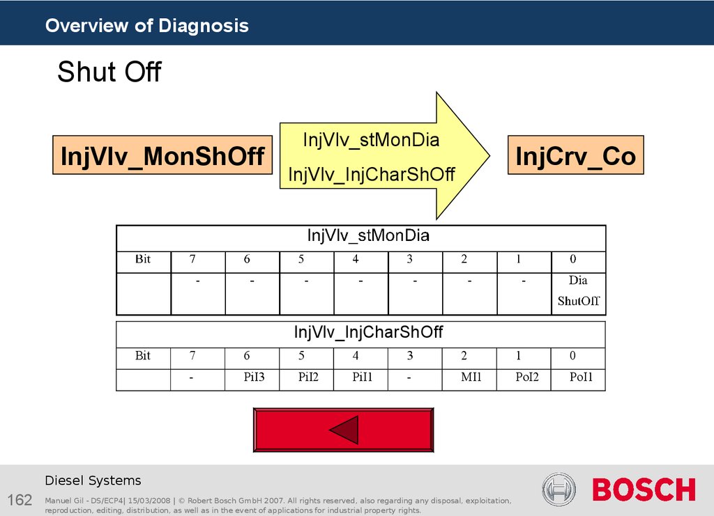
InjVlv_stMonDia
InjVlv_stMonDia
InjVlv_InjCharShOff
InjVlv_InjCharShOff
InjCrv_Co
InjCrv_Co
Diesel Systems
89
Manuel Gil - DS/ECP4| 15/03/2008 | © Robert Bosch GmbH 2007. All rights reserved, also regarding any disposal, exploitation,
reproduction, editing, distribution, as well as in the event of applications for industrial property rights.
Manuel Gil - DS-NF/EAN4
90. Scheduling of the diagnosis Shut Off
Overview of DiagnosisScheduling of the diagnosis Shut Off
This function checks the error paths relevant to an injector and Shuts Off an injector or bank to
enable continued driving using the injector bank which is still working.
Via application, a "Switch-On-Test" can be performed.
The function InjVlv_MonShoff must be scheduled right before the injection coordinator
(InjCrv_Co). No other process is allowed to be scheduled between this two processes.
InjVlv_MonShOff_Proc
InjVlv_MonShOff_Proc
InjVlv_Mon_Proc
InjVlv_Mon_Proc
InjCrv_Co_Proc
InjCrv_Co_Proc
Diesel Systems
90
Manuel Gil - DS/ECP4| 15/03/2008 | © Robert Bosch GmbH 2007. All rights reserved, also regarding any disposal, exploitation,
reproduction, editing, distribution, as well as in the event of applications for industrial property rights.
Manuel Gil - DS-NF/EAN4
91. State machine of the diagnosis Shut Off (1)
Overview of DiagnosisState machine of the diagnosis Shut Off (1)
1
b
1a
DFP OK
Fid not inhibit
ShutOff_st OK
2
DFP DEFECT
Fid inhibit
ShutOff_st WAIT
4
a
3
a
DFP DEFECT
Fid inhibit
ShutOff_st TEST
3
b
DFP DEFECT
Fid inhibit
ShutOff_st OFF
3c
DFP PRE_OK
Fid inhibit
ShutOff_st WAIT
4
b
DFP PRE_OK
Fid inhibit
ShutOff_st TEST
5
Transtion 1a: “Switch-On-Test" is applied (InjVlv_numTest_C > 0).
An error is detected, debounced and Shut Off Fid (Fid_Bnk%ShOffTest/Fid_Cyl%ShOffTest)
is activated; the applied cylinders will be disconnected and the system stays in Shut Off
state "WAIT“.
Diesel Systems
91
Manuel Gil - DS/ECP4| 15/03/2008 | © Robert Bosch GmbH 2007. All rights reserved, also regarding any disposal, exploitation,
reproduction, editing, distribution, as well as in the event of applications for industrial property rights.
92. State machine of the diagnosis Shut Off (2)
Overview of DiagnosisState machine of the diagnosis Shut Off (2)
1
b
1
a
DFP OK
Fid not inhibit
ShutOff_st OK
2
DFP DEFECT
Fid inhibit
ShutOff_st WAIT
4
a
3
a
DFP DEFECT
Fid inhibit
ShutOff_st TEST
3
b
DFP DEFECT
Fid inhibit
ShutOff_st OFF
3c
DFP PRE_OK
Fid inhibit
ShutOff_st WAIT
4
b
DFP PRE_OK
Fid inhibit
ShutOff_st TEST
5
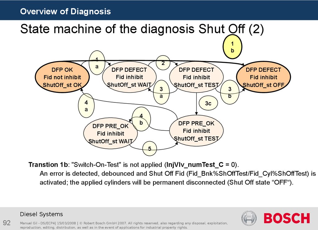
Transtion 1b: "Switch-On-Test" is not applied (InjVlv_numTest_C = 0).
An error is detected, debounced and Shut Off Fid (Fid_Bnk%ShOffTest/Fid_Cyl%ShOffTest) is
activated; the applied cylinders will be permanent disconnected (Shut Off state “OFF“).
Diesel Systems
92
Manuel Gil - DS/ECP4| 15/03/2008 | © Robert Bosch GmbH 2007. All rights reserved, also regarding any disposal, exploitation,
reproduction, editing, distribution, as well as in the event of applications for industrial property rights.
93. State machine of the diagnosis Shut Off (3)
Overview of DiagnosisState machine of the diagnosis Shut Off (3)
1
b
1
a
DFP OK
Fid not inhibit
ShutOff_st OK
2
DFP DEFECT
Fid inhibit
ShutOff_st WAIT
4
a
3
a
DFP DEFECT
Fid inhibit
ShutOff_st TEST
3
b
DFP DEFECT
Fid inhibit
ShutOff_st OFF
3c
DFP PRE_OK
Fid inhibit
ShutOff_st WAIT
4
b
DFP PRE_OK
Fid inhibit
ShutOff_st TEST
5
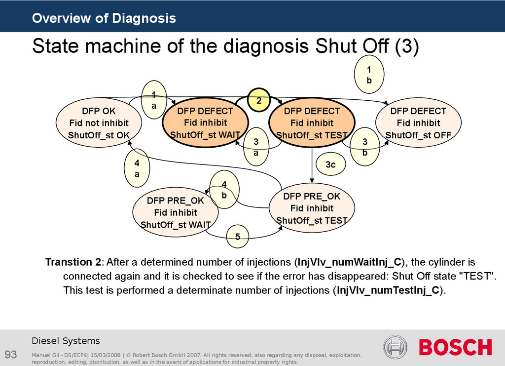
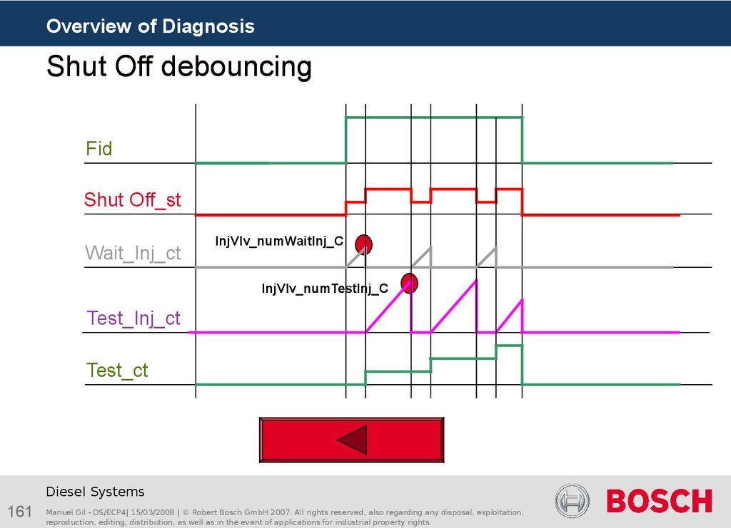
Transtion 2: After a determined number of injections (InjVlv_numWaitInj_C), the cylinder is
connected again and it is checked to see if the error has disappeared: Shut Off state "TEST".
This test is performed a determinate number of injections (InjVlv_numTestInj_C).
Diesel Systems
93
Manuel Gil - DS/ECP4| 15/03/2008 | © Robert Bosch GmbH 2007. All rights reserved, also regarding any disposal, exploitation,
reproduction, editing, distribution, as well as in the event of applications for industrial property rights.
94. State machine of the diagnosis Shut Off (4)
Overview of DiagnosisState machine of the diagnosis Shut Off (4)
1
b
1
a
DFP OK
Fid not inhibit
ShutOff_st OK
2
DFP DEFECT
Fid inhibit
ShutOff_st TEST
DFP DEFECT
Fid inhibit
ShutOff_st WAIT
3a
4
a
3
b
DFP DEFECT
Fid inhibit
ShutOff_st OFF
3c
DFP PRE_OK
Fid inhibit
ShutOff_st WAIT
4
b
DFP PRE_OK
Fid inhibit
ShutOff_st TEST
5
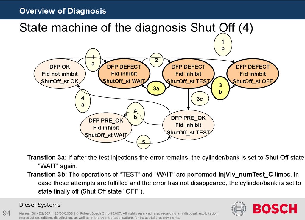
Transtion 3a: If after the test injections the error remains, the cylinder/bank is set to Shut Off state
"WAIT" again.
Transtion 3b: The operations of “TEST” and “WAIT” are performed InjVlv_numTest_C times. In
case these attempts are fulfilled and the error has not disappeared, the cylinder/bank is set to
state finally off (Shut Off state "OFF").
Diesel Systems
94
Manuel Gil - DS/ECP4| 15/03/2008 | © Robert Bosch GmbH 2007. All rights reserved, also regarding any disposal, exploitation,
reproduction, editing, distribution, as well as in the event of applications for industrial property rights.
95. State machine of the diagnosis Shut Off (5)
Overview of DiagnosisState machine of the diagnosis Shut Off (5)
1
b
1
a
DFP OK
Fid not inhibit
ShutOff_st OK
2
DFP DEFECT
Fid inhibit
ShutOff_st TEST
DFP DEFECT
Fid inhibit
ShutOff_st WAIT
3a
4
a
3
b
3c
DFP PRE_OK
Fid inhibit
ShutOff_st WAIT
4
b
DFP PRE_OK
Fid inhibit
ShutOff_st TEST
5
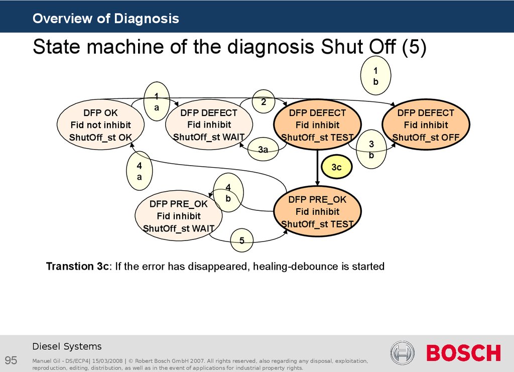
Transtion 3c: If the error has disappeared, healing-debounce is started
Diesel Systems
95
Manuel Gil - DS/ECP4| 15/03/2008 | © Robert Bosch GmbH 2007. All rights reserved, also regarding any disposal, exploitation,
reproduction, editing, distribution, as well as in the event of applications for industrial property rights.
DFP DEFECT
Fid inhibit
ShutOff_st OFF
96. State machine of the diagnosis Shut Off (6)
Overview of DiagnosisState machine of the diagnosis Shut Off (6)
1
b
DFP OK
Fid not inhibit
ShutOff_st OK
1
a
2
DFP DEFECT
Fid inhibit
ShutOff_st TEST
DFP DEFECT
Fid inhibit
ShutOff_st WAIT
3a
3
b
DFP DEFECT
Fid inhibit
ShutOff_st OFF
3c
4a
DFP PRE_OK
Fid inhibit
ShutOff_st WAIT
4
b
DFP PRE_OK
Fid inhibit
ShutOff_st TEST
5
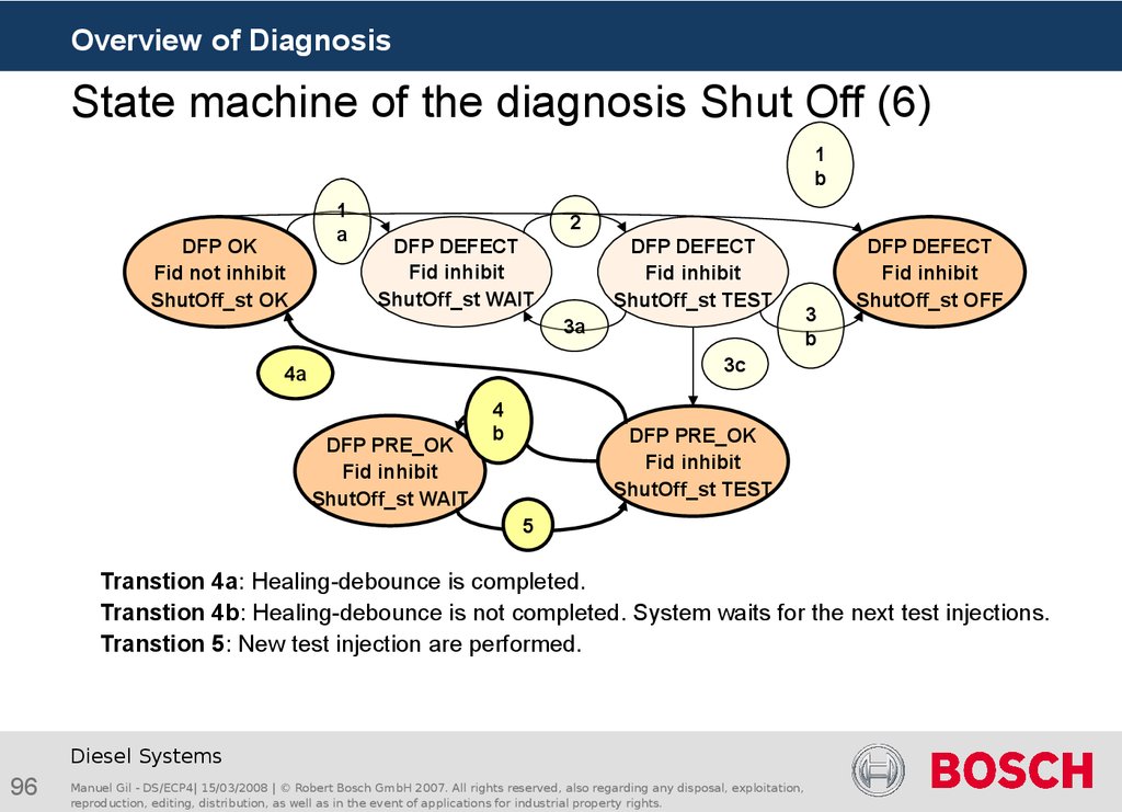
Transtion 4a: Healing-debounce is completed.
Transtion 4b: Healing-debounce is not completed. System waits for the next test injections.
Transtion 5: New test injection are performed.
Diesel Systems
96
Manuel Gil - DS/ECP4| 15/03/2008 | © Robert Bosch GmbH 2007. All rights reserved, also regarding any disposal, exploitation,
reproduction, editing, distribution, as well as in the event of applications for industrial property rights.
97. Folie 97
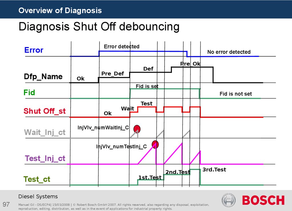
Overview of DiagnosisDiagnosis Shut Off debouncing
Error detected
Error
Dfp_Name
Ok
Pre_Def
Wait_Inj_ct
Def
Pre_Ok
Fid is set
Fid
Shut Off_st
No error detected
Fid is not set
Ok
Wait
Test
InjVlv_numWaitInj_C
InjVlv_numTestInj_C
Test_Inj_ct
Test_ct
1st.Test
2nd.Test
3rd.Test
Diesel Systems
97
Manuel Gil - DS/ECP4| 15/03/2008 | © Robert Bosch GmbH 2007. All rights reserved, also regarding any disposal, exploitation,
reproduction, editing, distribution, as well as in the event of applications for industrial property rights.
98. Shut Off Application
Overview of DiagnosisShut Off Application
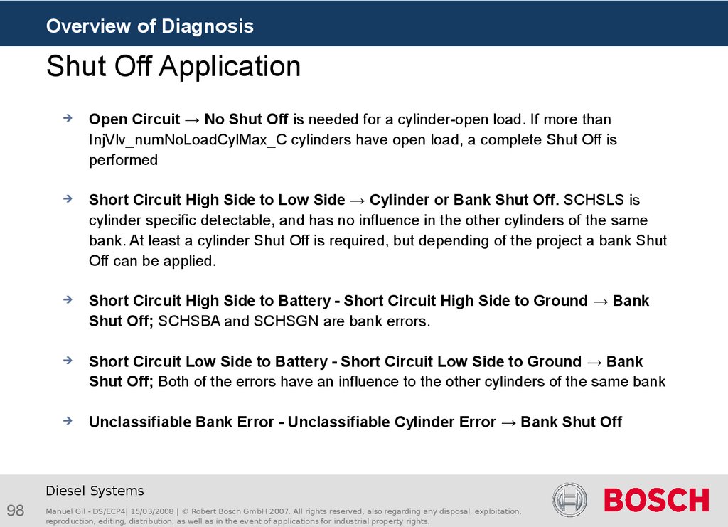
Open Circuit → No Shut Off is needed for a cylinder-open load. If more than
InjVlv_numNoLoadCylMax_C cylinders have open load, a complete Shut Off is
performed
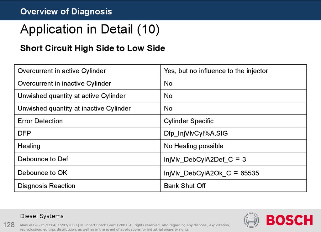
Short Circuit High Side to Low Side → Cylinder or Bank Shut Off. SCHSLS is
cylinder specific detectable, and has no influence in the other cylinders of the same
bank. At least a cylinder Shut Off is required, but depending of the project a bank Shut
Off can be applied.
Short Circuit High Side to Battery - Short Circuit High Side to Ground → Bank
Shut Off; SCHSBA and SCHSGN are bank errors.
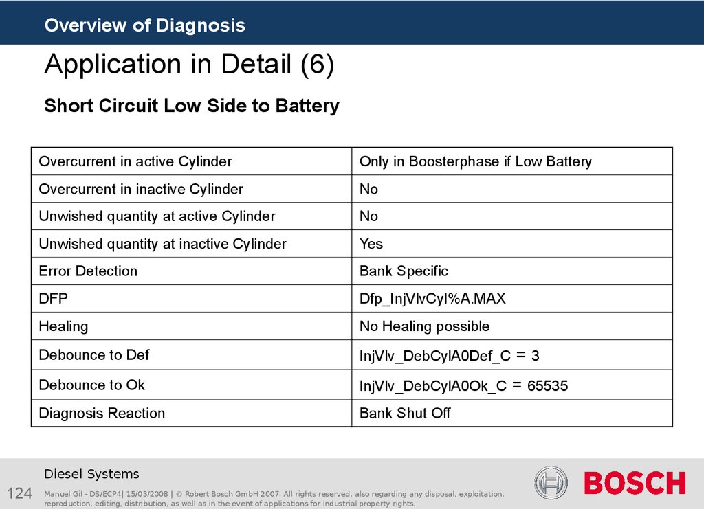
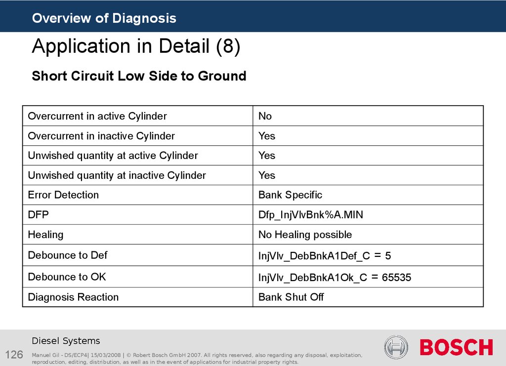
Short Circuit Low Side to Battery - Short Circuit Low Side to Ground → Bank
Shut Off; Both of the errors have an influence to the other cylinders of the same bank
Unclassifiable Bank Error - Unclassifiable Cylinder Error → Bank Shut Off
Diesel Systems
98
Manuel Gil - DS/ECP4| 15/03/2008 | © Robert Bosch GmbH 2007. All rights reserved, also regarding any disposal, exploitation,
reproduction, editing, distribution, as well as in the event of applications for industrial property rights.
99. InjVlv_MonShOff Labels
Overview of DiagnosisInjVlv_MonShOff Labels
Application parameters
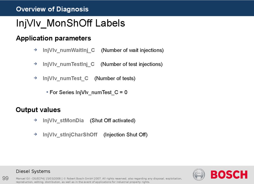
InjVlv_numWaitInj_C
(Number of wait injections)
InjVlv_numTestInj_C
(Number of test injections)
InjVlv_numTest_C
(Number of tests)
For Series InjVlv_numTest_C = 0
Output values
InjVlv_stMonDia
(Shut Off activated)
InjVlv_stInjCharShOff
(Injection Shut Off)
Diesel Systems
99
Manuel Gil - DS/ECP4| 15/03/2008 | © Robert Bosch GmbH 2007. All rights reserved, also regarding any disposal, exploitation,
reproduction, editing, distribution, as well as in the event of applications for industrial property rights.
100. Agenda
Overview of DiagnosisAgenda
Vision general of diagnosis
Solenoid Valve Monitoring of CR- & U-System
Outcomes of the Short Circuits
Solenoid Valve Monitoring Shut Off
Application procedure
Application procedure
Measure procedure in Truck
Breakout Box
Application process
Actual platform application
Peculiarity 8 Cylinder software with multiplexer
Diesel Systems
10
Manuel Gil - DS/ECP4| 15/03/2008 | © Robert Bosch GmbH 2007. All rights reserved, also regarding any disposal, exploitation,
reproduction, editing, distribution, as well as in the event of applications for industrial property rights.
101. Application procedure
Overview of DiagnosisApplication procedure
Hardware application hints
Measure process in Labor:
Perform the errors at the injector side
Perform the errors at the ECU side
Measures on different cylinders and banks under different operating conditions(low
idle, high revolution number, error applied before terminal 15 is activated, short
circuit with high and low ohm resistance, different battery voltages)
Measure process in Truck:
Perform the errors at the injector side
Measures on different cylinders and banks under different operating conditions (low
idle, high revolution number, error applied before terminal 15 is activated, short
circuit with high and low ohm resistance)
Measure analysis and compare with labor measurements and simulation
Calculate the Pattern and Select Matrix
Validation of the application
Diesel Systems
10
Manuel Gil - DS/ECP4| 15/03/2008 | © Robert Bosch GmbH 2007. All rights reserved, also regarding any disposal, exploitation,
reproduction, editing, distribution, as well as in the event of applications for industrial property rights.
102. Measure procedure in Truck
Overview of DiagnosisMeasure procedure in Truck
Ensure before the beginning of the measurements, that your vehicle has a series wiring
harness and all powerstage SSDs are project-specific correctly calibrated. This covers e.g.
the current profile, booster voltage, etc.
The measurements are worthless without pre-series-production hardware or with
defective calibration of the SSDs, because the CY33x error registers are dependent on
it.
Carry out the vehicle measurements with a breakout box.
Do not use any wiring harness adapter!
With help of the breakout box, the following errors have to be generated on each cylinder:
No Load (NL)
Short circuit High-Side to Ground (SCHSGN)
Short circuit High-Side to Battery (SCHSBA)
Short circuit Low-Side to Ground (SCLSGN)
Short circuit Low-Side to Battery (SCLSBA)
Short circuit High-Side to Low-Side (SCHSLS)
The measurements should be repeated more than once (for e.g. three times) under different
operating conditions (Low idle, Low-idle with increased rotational speed, Start of engine with
the error).
Diesel Systems
10
Manuel Gil - DS/ECP4| 15/03/2008 | © Robert Bosch GmbH 2007. All rights reserved, also regarding any disposal, exploitation,
reproduction, editing, distribution, as well as in the event of applications for industrial property rights.
103. Breakout Box
Overview of DiagnosisBreakout Box
ECU
Short
ShortCircuit
Circuit
Terminal
Terminal
ENGINE
Diesel Systems
10
Manuel Gil - DS/ECP4| 15/03/2008 | © Robert Bosch GmbH 2007. All rights reserved, also regarding any disposal, exploitation,
reproduction, editing, distribution, as well as in the event of applications for industrial property rights.
104. Breakout Box – Open Circuit
Overview of DiagnosisBreakout Box – Open Circuit
ECU
ENGINE
BATTERY
Open
OpenCircuit
Circuit
Diesel Systems
10
Manuel Gil - DS/ECP4| 15/03/2008 | © Robert Bosch GmbH 2007. All rights reserved, also regarding any disposal, exploitation,
reproduction, editing, distribution, as well as in the event of applications for industrial property rights.
105. Breakout Box – Short Circuit to Battery/Ground
Overview of DiagnosisBreakout Box – Short Circuit to Battery/Ground
ECU
ENGINE
BATTERY
Short
ShortCircuit
Circuitto
toBattery,
Battery,
Short
ShortCircuit
CircuittotoGround
Ground
Diesel Systems
10
Manuel Gil - DS/ECP4| 15/03/2008 | © Robert Bosch GmbH 2007. All rights reserved, also regarding any disposal, exploitation,
reproduction, editing, distribution, as well as in the event of applications for industrial property rights.
106. Breakout Box – Short Circuit High Side - Low Side
Overview of DiagnosisBreakout Box – Short Circuit High Side - Low Side
ECU
ENGINE
BATTERY
Diesel Systems
10
Manuel Gil - DS/ECP4| 15/03/2008 | © Robert Bosch GmbH 2007. All rights reserved, also regarding any disposal, exploitation,
reproduction, editing, distribution, as well as in the event of applications for industrial property rights.
Short
ShortCircuitCoil
CircuitCoil
107. Application process
Overview of DiagnosisApplication process
Diesel Systems
10
Manuel Gil - DS/ECP4| 15/03/2008 | © Robert Bosch GmbH 2007. All rights reserved, also regarding any disposal, exploitation,
reproduction, editing, distribution, as well as in the event of applications for industrial property rights.
108. Application process
Overview of DiagnosisApplication process
Diesel Systems
10
Manuel Gil - DS/ECP4| 15/03/2008 | © Robert Bosch GmbH 2007. All rights reserved, also regarding any disposal, exploitation,
reproduction, editing, distribution, as well as in the event of applications for industrial property rights.
109. Application process
Overview of DiagnosisApplication process
Diesel Systems
10
Manuel Gil - DS/ECP4| 15/03/2008 | © Robert Bosch GmbH 2007. All rights reserved, also regarding any disposal, exploitation,
reproduction, editing, distribution, as well as in the event of applications for industrial property rights.
110. Application process
Overview of DiagnosisApplication process
Diesel Systems
11
Manuel Gil - DS/ECP4| 15/03/2008 | © Robert Bosch GmbH 2007. All rights reserved, also regarding any disposal, exploitation,
reproduction, editing, distribution, as well as in the event of applications for industrial property rights.
111. Application process
Overview of DiagnosisApplication process
Diesel Systems
11
Manuel Gil - DS/ECP4| 15/03/2008 | © Robert Bosch GmbH 2007. All rights reserved, also regarding any disposal, exploitation,
reproduction, editing, distribution, as well as in the event of applications for industrial property rights.
112. Application process
Overview of DiagnosisApplication process
Diesel Systems
11
Manuel Gil - DS/ECP4| 15/03/2008 | © Robert Bosch GmbH 2007. All rights reserved, also regarding any disposal, exploitation,
reproduction, editing, distribution, as well as in the event of applications for industrial property rights.
113. Application process
Overview of DiagnosisApplication process
Diesel Systems
11
Manuel Gil - DS/ECP4| 15/03/2008 | © Robert Bosch GmbH 2007. All rights reserved, also regarding any disposal, exploitation,
reproduction, editing, distribution, as well as in the event of applications for industrial property rights.
114. Application process
Overview of DiagnosisApplication process
Diesel Systems
11
Manuel Gil - DS/ECP4| 15/03/2008 | © Robert Bosch GmbH 2007. All rights reserved, also regarding any disposal, exploitation,
reproduction, editing, distribution, as well as in the event of applications for industrial property rights.
115. Application process
Overview of DiagnosisApplication process
Diesel Systems
11
Manuel Gil - DS/ECP4| 15/03/2008 | © Robert Bosch GmbH 2007. All rights reserved, also regarding any disposal,












 Электроника


