")

")


")


")
")


")
 injector")
 Промышленность
 Реклама
Похожие презентации:


CM D-2.2L Engine
1.
CMD-2.2L Engine
( EURO-IV D-2.2L CRDi )
2.
EURO III vs EURO IV2
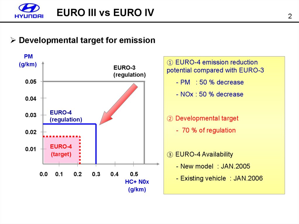
Developmental target for emission
PM
(g/km)
EURO-3
(regulation)
0.05
① EURO-4 emission reduction
potential compared with EURO-3
- PM : 50 % decrease
- NOx : 50 % decrease
0.04
EURO-4
(regulation)
0.03
② Developmental target
- 70 % of regulation
0.02
EURO-4
(target)
0.01
③ EURO-4 Availability
- New model : JAN.2005
0.0
0.1
0.2
0.3
0.4
0.5
HC+ N0x
(g/km)
- Existing vehicle : JAN.2006
3.
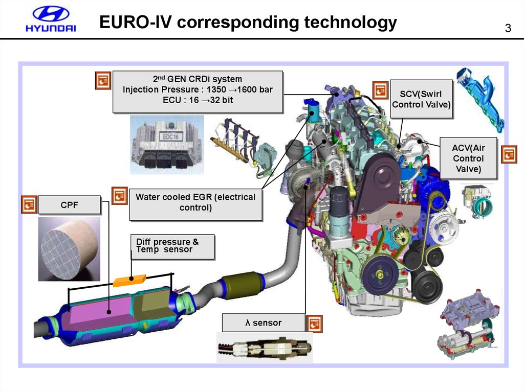
EURO-IV corresponding technology2nd GEN CRDi system
Injection Pressure : 1350 →1600 bar
ECU : 16 →32 bit
3
SCV(Swirl
Control Valve)
ACV(Air
Control
Valve)
CPF
Water cooled EGR (electrical
control)
Diff pressure &
Temp sensor
λ sensor
4. Comparative table ( EURO-III vs EURO-IV)
ItemsEmission regulation
EURO-III
EURO-IV
CO
0.64g/km
0.50g/km
Nox
0.50g/km
0.25g/km
HC
0.56g/km
0.30g/km
PM
0.05g/km
0.025g/km
15%
10%
16 bit CPU
32 bit CPU
121
154
Internal
Engine room
X
○
soot
Speed
ECM
Pins
Location
Λ(Oxygen) sensor
CPF(Catalyzed Particulary Filter)
4
Remark
Depending on vehicle
For EGR control
U-Eng
-
D-Eng
○
X
U-Eng
-
X
D-Eng
○
Reduce PM
X
CPF Diff pressure & temp sensor
Detect internal pressure & temp
SCV(Swirl Control Valve)
X
○
Fuel temp sensor
X
○
MPROM
○
○
Inlet control – A, J Eng
PCV(Pressure Control Valve)
X
○
Outlet control – D Eng
Rail pressure
control
Injector
Multi-injection
Pressure
Throttle flap control
1 Pilot, 1 Main
250~1350bar
type
Classfied (C1,C2,C3)
Control time
Key off (NVH reduced)
way
ON/OFF
2 Pilot, 1 Main,2 Post
Reduce smoke during low-mid
D-Eng: 2 Post injection
250~1600bar
7-code (IQA)
-Key off (NVH reduced)
-always (support EGR)
PWM control (300Hz)
Close the throttle when a key is
off to prevent from dieseling.
5.
D-2.0L vs D-2.2LEngine
5
D-2.0 CRDi
D-2.2 CRDi
displacemnet
1,991 cc
2,188 cc
PS
125 PS
153 PS
Torque
29.0 kg·m
35.0 kg·m
shape
Bore x stroke
Features
83×92
87×92
• BOSCH 1st GEN
• BOSCH 2nd GEN
• Fuel pressure control
• Fuel pressure control
- Outlet control
- Inlet & outlet control
- 1,350bar
- 1,600bar
• Swirl Control Valve
• Air Control Valve
• Catalyzed Particulate Filter - Euro Ⅳ
6. Input / output (EURO-III and EURO-IV)
InjectionAPS 1, 2
Brake, clutch S/W
6
BOSCH
inlet
CKPS & CMPS
ECM
Boost pressure&temp sensor
EURO-III
EURO-IV
Fuel pressure sensor
HFM5/HFM6
Fuel temp sensor
WTS, AFS
Blower, A/C S/W
A/C S/W
Rail pressure
control
outlet
EGR control
SCV control
Cooling fan control
A/C comp relay
PTC control
Glow plug control
ACV control
λ sensor
CAN/K-line
DPF diff & temp sensor
MIL/glow lamp
※ shadow=> EURO4
7. EURO-IV injection
Starting7
Burning
un burned
HC
Noise.vibrati
on
regeneratio
n
[500℃↑]
Injection timing
type
Purpose
Max advanced
Max retard
Pilot2
BTDC 100o
SOE(Pil1)+150 μs + ET(Pil2)
starting
Pilot1
BTDC 100o
SOE(MI) + 150 μs + ET(Pil1)
Reducing smoke
NVH
Main
BTDC 40o
ATDC 10o
Improving torque
Post2
SOE(MI)
+ ET(MI) + 150 μs
ATDC 40o
Increasing CPF temp
Next cylinder max. advanced
Activate oxidation
catayst
(burning soot)
Post1
ATDC 40o
SOE (Start Of Energizing) ET (Energizing Time)
8. Burning procedure for diesel engine
8Flame depending on pilot injection or not
60
Without pilot injection
pilot w/o
pilot with
50
Combustion pressure (bar)
Injection volume : 7mg
Fuel pressure : 1000bar
RPM : 1000rpm
Injection timing : BTDC 22
40
30
20
10
0
With pilot injection
-50
-40
-30
-20
-10
0
10
20
Crank angle (deg CA)
30
40
50
60
9. Diesel exhaust gas
9* PM : Particulate Matter
10
10
G asoline(3-w ay catalyst)
7
D iesel(no catalyst)
6 5.7
D iesel(D O C )
5
1.4 1.0
HC
1 0.7
CO
NNOx
Ox
PPM
M
Heart of aftertreatment is reducing Nox & PM
0
10.
CPF(Catalyzed Particulate Filter)
11. What is PM (Particulate Material or Matter)
Specialty Definition: PARTICULATE MATTEREnergy
Unburned fuel particles that form smoke or soot and stick to lung tissue when
inhaled. A chiefcomponent of exhaust emissions from heavy-duty diesel engines.
(PM).
Environment
Dust, soot, other tiny bits of solid materials that are released into and move around in
the air.
Weather
(PM) Solid particles or liquid droplets suspended or carried in the air (e.g., soot, dust,
fumes, mist) . Very small pieces of solid or liquid matter, such as particles of soot,
dust, aerosols, fumes, or mists.
11
12. Components of PM
The main component of PM is the unburnedcarbon solid particleof 15-30nm diameter, gas
phase-from fuel and partly from lubricant, and all
named as fines, dust, soot, mist, fog, and smog
are a part of PM.
SOL (Solid fraction) : elemental carbon / ash
SOF (soluble organic fraction) : organic material from engine oil and fuel
Absorbed Hydrocabons
Sulfate : sulfate acid / water
Soot(carbon material)
12
13. Catalystic converter terms
Kinds of catalystic converter depending on locationMCC (Manifold Catalytic Converter)
CCC (Close-Coupled Catalytic Converter)
WCC (Warm-up Catalytic Converter)
UCC (Under-floor Catalytic Converter)
13
MCC
Components of catalystic converter
Washcoat : coating material including catalyst. Mainly Al2O3 is used.
CCC
Substrate : honeycomb shape which is coated by washcoat.
Exhaust gas pass through this. Effect of reducing exhaust gas is
different depending on shape or thickness of substrate.
Support : support the substrate by using STS wire or matt.
WCC
UCC
14. Catalystic converter terms
WashcoatSubstrate
14
15. Precious metals for vehicle
15Pd : Purify HC mainly. Thermal resistance is good. Using in CCC
using as Pd only or Pd-Rh
Pt : Purify CO, Nox mainly. Thermal resistance is lower than Pd using in UCC
using as Pt-Rh or Pd-Pt-Rh
Rh : purify Nox mainly.price is much higher than Pd, Pt
70
Pd
Pt
Rh
60
price(US /g)
50
40
30
20
10
0
'99. 03
'99. 09
'00. 03
'00. 09
'00. 12
'01. 01
Cost change of precious metals
'01. 03
'01. 05
16. Catalyst Deactivation Mechanism
16Poisoning
Selective Catalyst Poisoning
poisoning by Pb, Hg, Cd
deactivation by SO2
recovery by thermal treatment,
washing
Catalyst Fouling
nonselective poisoning,
masking
by P (engine oil)
Selective Catalyst
Poisoning
Catalyst Fouling
Thermal Deactivation
Catalyst Sintering
sintering, cohesion of precious
metals
using Stabilizer CeO2, La2O3
Catalyst Sintering
Washcoat Sintering
Washcoat Sintering
using Stabilizer BaO, La2O3,
SiO2, ZrO2
17. Diesel aftertreatment
17NOx / PM Control
PM
NOx
SOFs
DeNOx
LNT
SCR
LNT (Lean NOx Trap)
SCR (Selective Catalytic Reduction)
DOC
Solids
DPF & CPF
Active
DOC (Diesel Oxidation Catalyst)
DPF (Diesel Particulate Filter)
CPF (Catalyzed Particulate Filter)
SOF(Soluble Organic Fraction)
Combination
Passive
18.
PM reducing device18
PM reducing device
CPF
(Catalyzed Particulate Filter)
DPF+Additive
(Diesel Particulate Filter)
CRT
(Continuously Regenerating Trap)
Oxidatio
n
Catalyst
▶ Burning a soot by post injection &
oxidating a soot by using activation of
coated catalyst (using NO2)
▶ Simple system (no special fuel adding
device)
▶ need a strategy of controlling
regeneration temp.
▶ Problem (recovery of waste DPF &
Particulate
Filter
▶ Burning the soot by post injection &
▶ Burning the soot continuously by
cerium-based additive(around 450℃, at
oxidated NO2(through DOC), without
every 500km forced regeneration )
post injection
▶ sophistcated system(fuel adding
▶ On the testing at bus(LONDON)
device)
▶ impossible to adapt to passenger
▶ Problem (lots of CO emission)
vehicle (exhaust gas temp is too low)
▶ Peugeot, Volkswagen, FORD
▶ adapted to commercial diesel
cleaning)
▶ adapted to almost European
passenger diesel
19.
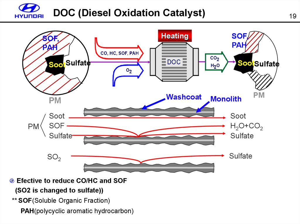
DOC (Diesel Oxidation Catalyst)SOF,
PAH
Heating
SootSulfate
PM
PM
19
SOF,
PAH
SootSulfate
Washcoat
Monolith
PM
Soot
SOF
Sulfate
Soot
H2O+CO2
Sulfate
SO2
Sulfate
Efective to reduce CO/HC and SOF
(SO2 is changed to sulfate))
** SOF(Soluble Organic Fraction)
PAH(polycyclic aromatic hydrocarbon)
20.
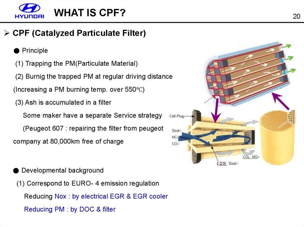
WHAT IS CPF?CPF (Catalyzed Particulate Filter)
● Principle
(1) Trapping the PM(Particulate Material)
(2) Burnig the trapped PM at regular driving distance
(Increasing a PM burning temp. over 550℃)
(3) Ash is accumulated in a filter
Some maker have a separate Service strategy
(Peugeot 607 : repairing the filter from peugeot
company at 80,000km free of charge
● Developmental background
(1) Correspond to EURO- 4 emission regulation
Reducing Nox : by electrical EGR & EGR cooler
Reducing PM : by DOC & filter
20
21. CPF passive soot regeneration
C(soot) + NO2 CO/CO2 + NONO + O2 NO2
NO2 turn over :
( by using NO2 2~4 C burning )
C(Particulate) + O CO/CO
CO + O2 CO2 (CO from soot)
HC,CO + O2 CO2 + H2O
(residual gaseous HC,CO)
** Passive : without any additive mechanism
Active : with additive mechanism (post injection)
21
22. CPF active soot regeneration
Increasing temp. of exhaust gas through post injection and DOC burning soot22
23.
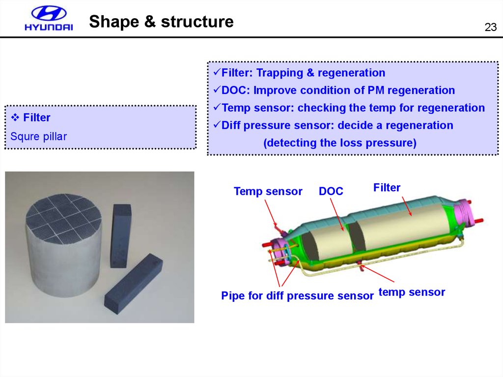
Shape & structure23
Filter: Trapping & regeneration
DOC: Improve condition of PM regeneration
Filter
Squre pillar
Temp sensor: checking the temp for regeneration
Diff pressure sensor: decide a regeneration
(detecting the loss pressure)
Temp sensor
DOC
Filter
Pipe for diff pressure sensor temp sensor
24.
System overviewHigh pressure pump
CRDi
ENG
24
Fuel pump
Post injection
Exhaust gas
Pressure /temp sensor
DOC
머플러
Catlystic filter
CRDi
ECU
PM accumulated & burning
25.
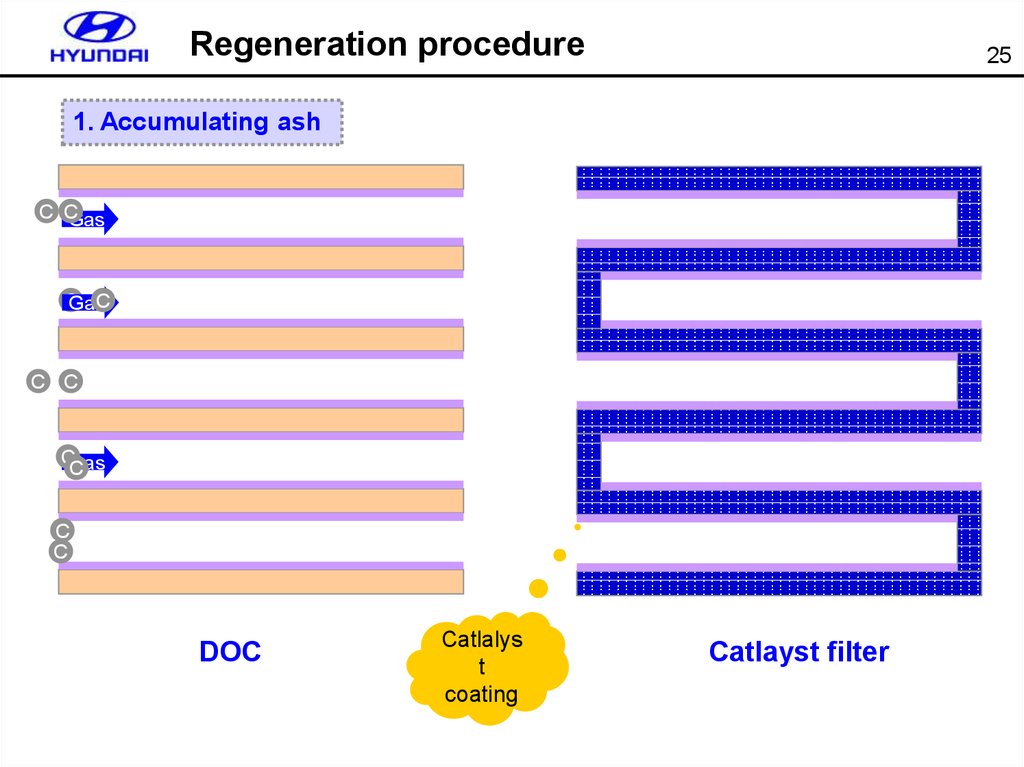
Regeneration procedure25
1. Accumulating ash
C CGas
CGasC
C C
CGas
C
C
C
DOC
Catlalys
t
coating
Catlayst filter
26.
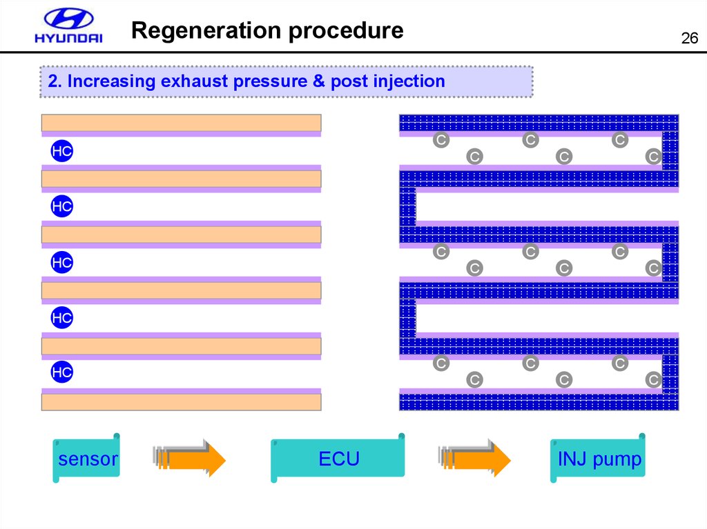
Regeneration procedure26
2. Increasing exhaust pressure & post injection
C
HC
C
C
C
C
C
HC
C
HC
C
C
C
C
C
HC
C
HC
sensor
C
C
ECU
C
C
INJ pump
C
27.
Regeneration procedure27
3. PM regeneration
`
HC O2
CO2+Heat
HC O2
CO2+Heat
HC O2 CO2+Heat
HC O2
C
O2
C
O2
C O2
C
O2
O2 C
C
O2
O2
C
C O2
C
O2
O2 C
C
O2
O2
C
C O2
C
O2
O2 C
C
O2
O2
C
CO2+Heat
HC O2 CO2+Heat
C
O2
Exhaust temp is increased by post injection
DOC adjust the exhaust temp (regeneration temp)
PM is regenerated and filter temp is increasing
28.
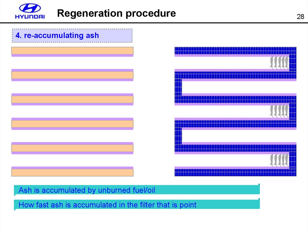
Regeneration procedure4. re-accumulating ash
Ash is accumulated by unburned fuel/oil
How fast ash is accumulated in the filter that is point
28
29. KM & JM exhaust system overview
KM & JM exhaust system overviewDiff pressure sensor
Air gap insulator pipe
Temp sensor
Main muffler
DOC + CPF
29
30.
CPF regeneration conditionRegeneration mode condition
Drving distance: every 1,000km
Engine RPM: 1,000RPM ~ 4,000RPM
Engine load: around 0.7bar( over 8mg/st )
Vehicle speed : over 5km/h
Water temp : over 40℃
Notice) shock or noise may occurred by changing torque during regeneration
30
31. Regeneration method
Mid/highspeed
31
Driving distance
Safety
Diff
pressure
SOOT volume
SIMULATION
Low speed
32.
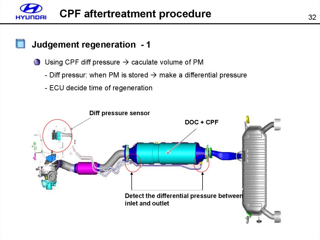
CPF aftertreatment procedureJudgement regeneration - 1
Using CPF diff pressure caculate volume of PM
- Diff pressur: when PM is stored make a differential pressure
- ECU decide time of regeneration
Diff pressure sensor
DOC + CPF
Detect the differential pressure between
inlet and outlet
32
33. Differential pressure model
CPF diff pressure+ diff sensor
+ temp sensor
Diff pressure by
ash
accumulation
33
Caculate volume
of soot
34.
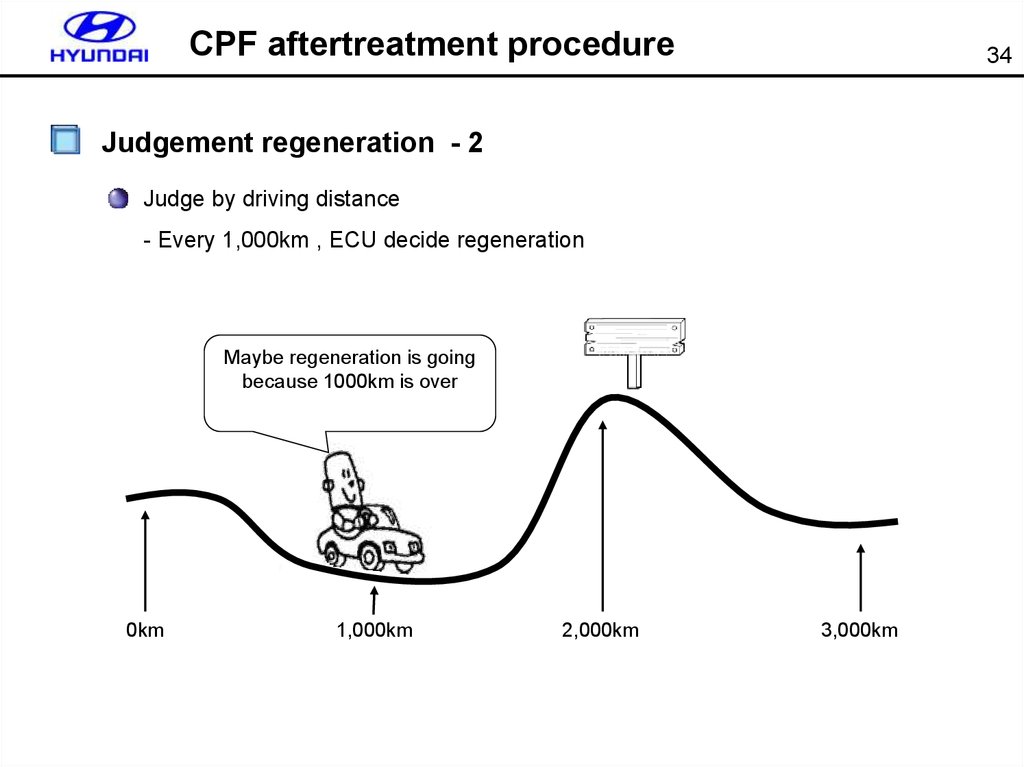
CPF aftertreatment procedure34
Judgement regeneration - 2
Judge by driving distance
- Every 1,000km , ECU decide regeneration
Maybe regeneration is going
because 1000km is over
0km
1,000km
2,000km
3,000km
35.
CPF aftertreatment procedure35
Judgement regeneration - 3
Predict the volume of PM by using simulation
Detect the volume of
accumulated PM and
burned PM
Detect the volume of
accumulated PM
depending on driving
condition
36. Simulation model
Normal drivingSoot&smoke
+ rpm
+ fuel
+ acceleration driving
+ enviromental condition
36
Caculate
accumulated soot
vol.
Rducing soot by regeneration
+ soot volume(g)
+ CPF proceding temp(℃)
+ O2 (kg/h)
37.
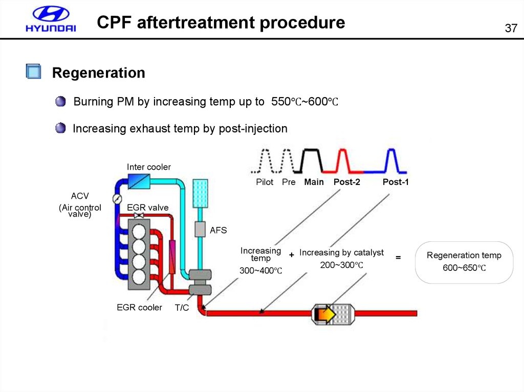
CPF aftertreatment procedure37
Regeneration
Burning PM by increasing temp up to 550℃~600℃
Increasing exhaust temp by post-injection
Inter cooler
Pilot
ACV
(Air control
valve)
Pre Main
Post-2
Post-1
EGR valve
AFS
Increasing
+ Increasing by catalyst
temp
200~300℃
300~400℃
EGR cooler
T/C
=
Regeneration temp
600~650℃
38. CPF component
38Differential pressure sensor
Detect the diff pressure between CPF inlet(upstream) and outlet(downstream)
Diff pressure 20~30kPa(200~300mbar) regeneration start
Output voltage: 1V ~ 4.5 V
output(V)
Diff sensor
4.5
Diff pipe
CPF
1
0
100
pressure(kPa)
39. CPF component
39Exhaust temp sensor
Monitoring the regeneration temp.(Obtain ignition temperature in particulate filter)
Temp sensor-1: protect VGT , located in exhaust gas
Temp sensor-2: feedback for regeneration
Temp sensor-2
Temp sensor-1
CPF
VGT
40.
Plan for CPF40
Plan for CPF
Adapted vehicle : D-RS, D-JM, D-KM, D-NF, D-MG, D-UN, D-CMAT, D-TGAT, D-FO, U-FCAT
section
2005
2006
2007
2008
EURO4
DOM
12
JM KM 9
(2MT2AT4MT) NF MG
FCAT
EURO4
3
5
UN TG
5
12
PO
CM
FO
FCMT
JM KM (4MT)
EUR
7
RS
9
12
2
JM NF
KM MG
(2M
T
2AT)
Notice) Plan is changeable
7
UN TG
CM
FO
FMC
F/L
R/C
41. CPF service regeneration by Hi-scan
4142. CPF service regeneration by Hi-scan
42EURO-IV
Additional
MENU for
CPF
T3/T5
temperature
43. Component change routine (ECU change)
Notice) If you change some partsrelated CPF you should do this
procedure.
INPUT THE CURRENT ODO VALUES IN
CLUSTER TO COUNT THE DRIFT SOOT
VALUE INFORMATION OF CPF.
000000 km
REFER TO PREVIOUS MENU TO SEE
INJECTOR INFORMATION.
PRESS [ENTER] KEY.
43
44. Component change routine (CPF change)
IN THIS MODE, CAN RESET THE DISTANCEOF LAST CHANGED CPF AND OTHERS
RELATED PARAMETERS.
PRESS [ENTER] KEY.
Notice) If you change the CPF then should reset the distance of last changed
CPF. Other related parts are same procedure(Lambda sensor , RPS, AFS,
Diff sensor SCV).
44
45. Current data
45Outlet & inlet
pressure
sensor
T3 & T5 temp
sensor
SCV & ACV
actuator
46. Actuation test
4647. Actuation test
4748. Actuation test
4849. Actuation test
ACVactuator test
SCV actuator
test
49
Inlet
pressure
valve test
Outlet
pressure valve
test
50. Actuation test
5051. Injection correction (IQA)
51CONDITION:IG.KEY ON(ENGINE STOP)
1.
IF THE INJ IS CHANGED, THE INJ CORRECTION
FUNC. SHOULD BE PERFORM TO CONTROL. THE
NORMAL FUEL INJ.
2.
TO INPUT THE INJECTOR NUMBER,PRESS SHIFT
KEY AND SELECT THE CYL. BY ARROW KEY AT
THE SAME TIME, AND INPUT THE INJ DATA BY
[F1]~[F6], DIGIT KEY. AND THEN PRESS [ENTER].
3.
AFTER COMPLETE, TURN THE IG.KEY OFF AND
RECHECK THE SYSTEM AFTER 10 SEC.
Enter the 7-digit
code