 Lecturer - Oreshkov Vasiliy Ivanovich")

 Интернет
 Информатика
Похожие презентации:
. Lecture 2")


. Lecture 6")


")
Coding technologies of linear signals in the XDSL. Lecture 3
1. Name of discipline: Transmission systems of access networks (TSAN) Lecturer - Oreshkov Vasiliy Ivanovich
2.
Lecture 3CODING TECHNOLOGIES OF
LINEAR SIGNALS IN THE
XDSL
3.
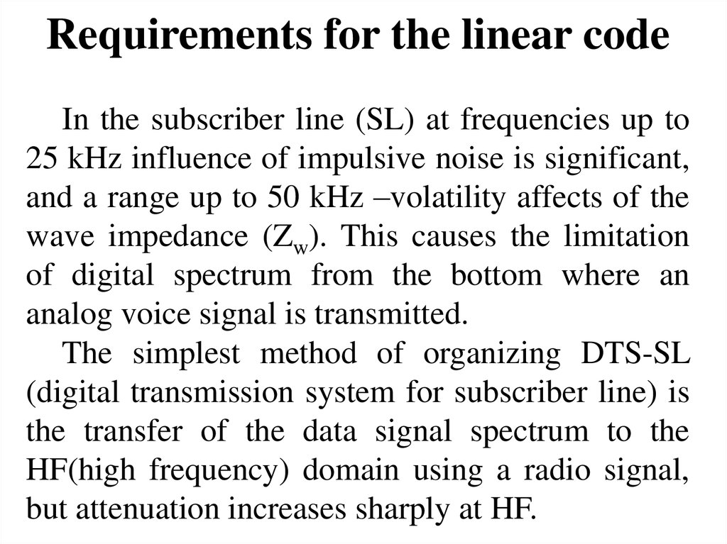
Requirements for the linear codeIn the subscriber line (SL) at frequencies up to
25 kHz influence of impulsive noise is significant,
and a range up to 50 kHz –volatility affects of the
wave impedance (Zw). This causes the limitation
of digital spectrum from the bottom where an
analog voice signal is transmitted.
The simplest method of organizing DTS-SL
(digital transmission system for subscriber line) is
the transfer of the data signal spectrum to the
HF(high frequency) domain using a radio signal,
but attenuation increases sharply at HF.
4.
Therefore, the linear range of the signal shouldbe limited to the top, otherwise installing repeaters
won’t be avoided, that is undesirable.
The following requirements should be taken into
account when choosing a method of line encoding
DTS-SL:
- Limitation of the signal above and below;
- The possibility of extraction of linear
synchronization signal;
- Monitoring and correction of errors without
interruption;
5.
- Provision of equipment for reverse polaritycircuit veins of SL;
- Simple (cheap) construction of the equipment,
minimizing the current RPS (remote power supply)
and dimensions of RT (remote terminal) and COT
(central office terminal).
6.
To perform these requirements special linearsignals (codes) can be designed. DTS-SL signal
passed along the chain composed of series
connected different types cables with different
conductors diameters.
The use of linear codes such as AMI, HDB-3
(RZ signal) leads to the formation of multiple
reflections and interference types associated flow.
7.
The implementation of xDSL technology ispossible with the using of new line-level signals
that can transmit data signal in a narrow band in
comparison with the codes plesiochronous DTS.
These types of modulation should also provide
the common transmission of an analog signal to
VB (voice band) and they shouldn’t contain
passive pause for reducing the impact of
associated flow.
The following types of linear modulation
signals in xDSL - BPS, 2B1Q; CAP; DMT and
TC-PAM:
8.
- RBPS - relative bi-pulse signal;- 2B1Q - 2 Binary, 1 Quartenary (2 bits of
information, level 4);
- CAP - Carrierless Amplitud and Phase
Modulation (AFM - amplitude and phase
modulation without a carrier);
- QAM - Quadrature Amplitude Modulation;
- DMT - Discret Multi-Tone (discrete multifrequency modulation);
- TC-PAM - Trellis Coded Pulse Amplitude
Modulation (pulse amplitude and phase
modulation with Trellis coding).
9.
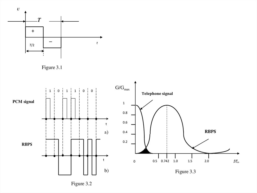
RBPS - relative bi-pulse signalThe first digital signal SL applied doublepulse signal wherein for each transmission symbol
of binary data (0, 1), for each clock interval two
pulses of different polarity with the duration T/2
were generated , Fig. 3.1.
Relative double-pulse signal is chosen for reasons of:
a) The balance of the DC (direct current);
b) The independence of the transmission quality
polarity wires in chain connected to the hardware.
Algorithm RDPS binary "1" is transmitted by the AMI
law, and a binary "0" is transmitted by double-pulse
signal (Fig. 3.2a, b).
10.
UТ
+
Т/2
–
t
Figure 3.1
1
0
1
1
0
G/Gmax
0
PCM signal
Telephone signal
1
0.8
t
0.6
а)
0.4
RBPS
0.2
RBPS
t
0
b)
Figure 3.2
0.5
0.742
1.0
1.5
Figure 3.3
2.0
f/fт
11.
Even in a perfectly balanced code RBPS lowpower spectral components are significant in the
range of VB channels (Figure 3.3), ie this code
does not provide a joint transmission without
interference of digital and analog signals over a
single pair of SL.
This problem is solved in the code 3B2T- RBPS,
so for rates of 192 kbit/s the bandwidth of: 5...140
kHz is occupied.
12.
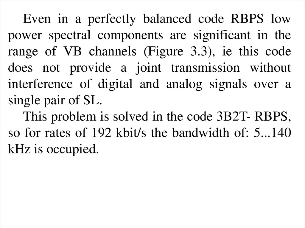
Linear signal 2В1Q2B1Q modulation (4-level PAM) is standardized
for networks ISDN, where the digital stream is
transmitted at a rate of 144 kbit / s. Later it began to
be used for transmission over high-speed streams in
the HDSL technology.
The code is modulated by a signal having a level
4, i.e. at each time two bits of information are
transmitted, Fig. 3.4 . Clock interval duration will be
increased, and the clock frequency - halved.
13.
103
11
Т
1
01
–1
t
00
–3
Figure 3.4
3 pairs
G(f)
2 pairs
100
500
1 pair
1000
Figure 3.5
1500
f, kHZ
14.
In the 2B1Q code the E1 stream transmission ispossible (in parts) for one, two or three pairs. For
HDSL technology transmission rate for three pairs
of 784 kbit/s, 2 pairs - 1168 kbit/s for 1 pair - 2320
kbit/s.
The energy spectrum is characterized by a
constant , low and high frequency components (Fig.
3.5). The latter fact reduces the maximum signal
transmission distance with the required quality.
Joint transmission of analog voice signal is not
possible.
15.
Technology 2B1Q is sensitive to low-frequencydistortion and noise, and an acceptable quality of
transmission is achieved by using modern methods
of correction.
Despite the fact that one pair of transmission does
not satisfy the basic requirements for transmission
range 2B1Q technology is widely used due to its
cheapness .
In addition , you should consider the fact that
foreign ( Western ) SL are shorter and have better
quality.
16.
QAM – Quadrature Amplitude ModulationAccording to this algorithm the coding is done by
simultaneous changing in-phase (cos2 fct) and
quadrature (sin2 fct) components of carrier harmonic
signal with frequency c = 2 fc , that have phase
difference on 90 ( /2).
A resultant QAM signal s(t) is equal to sum of
components:
s(t) = ак cos2 fct + bк sin2 fct,
sinphase component quadrature component
17.
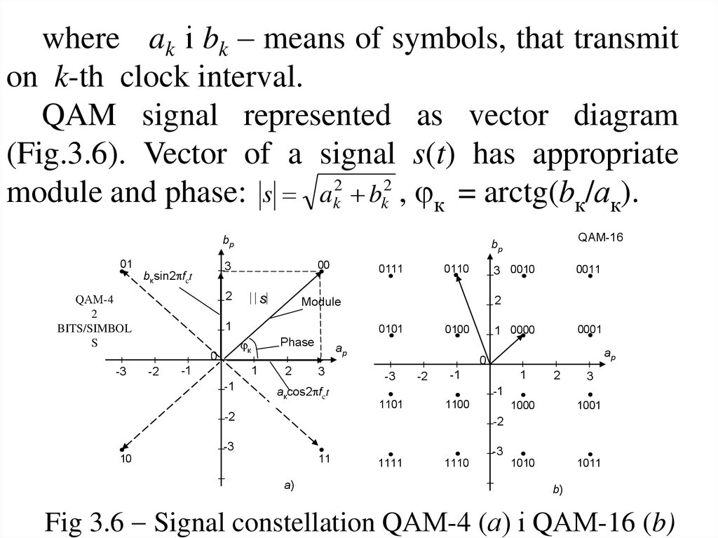
where ak і bk – means of symbols, that transmiton k-th clock interval.
QAM signal represented as vector diagram
(Fig.3.6). Vector of a signal s(t) has appropriate
module and phase: s ak2 bk2 , к = arctg(bк/ак).
bp
01
2
QАМ-4
2
BITS/SIMBOL
S
s
0111
-2
Phase
1
-1
3 0010
2
0100
ap
3
акcos2 fct
0011
2
0101
к
-1
0110
Module
1
0
-3
00
3
bкsin2 fct
QАМ-16
bp
0001
1 0000
ap
0
-3
-2
-1
1
2
3
-1
1101
1100
-2
1000
1001
1010
1011
-2
-3
10
11
а)
-3
1111
1110
b)
Fig 3.6 Signal constellation QАМ-4 (а) і QАМ-16 (b)
18.
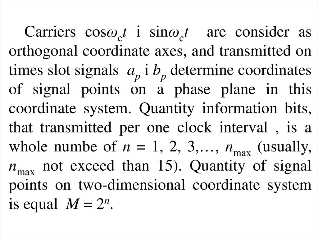
Carriers cosωct і sinωct are consider asorthogonal coordinate axes, and transmitted on
times slot signals ap і bp determine coordinates
of signal points on a phase plane in this
coordinate system. Quantity information bits,
that transmitted per one clock interval , is a
whole numbe of n = 1, 2, 3,…, nmax (usually,
nmax not exceed than 15). Quantity of signal
points on two-dimensional coordinate system
is equal M = 2n.
19.
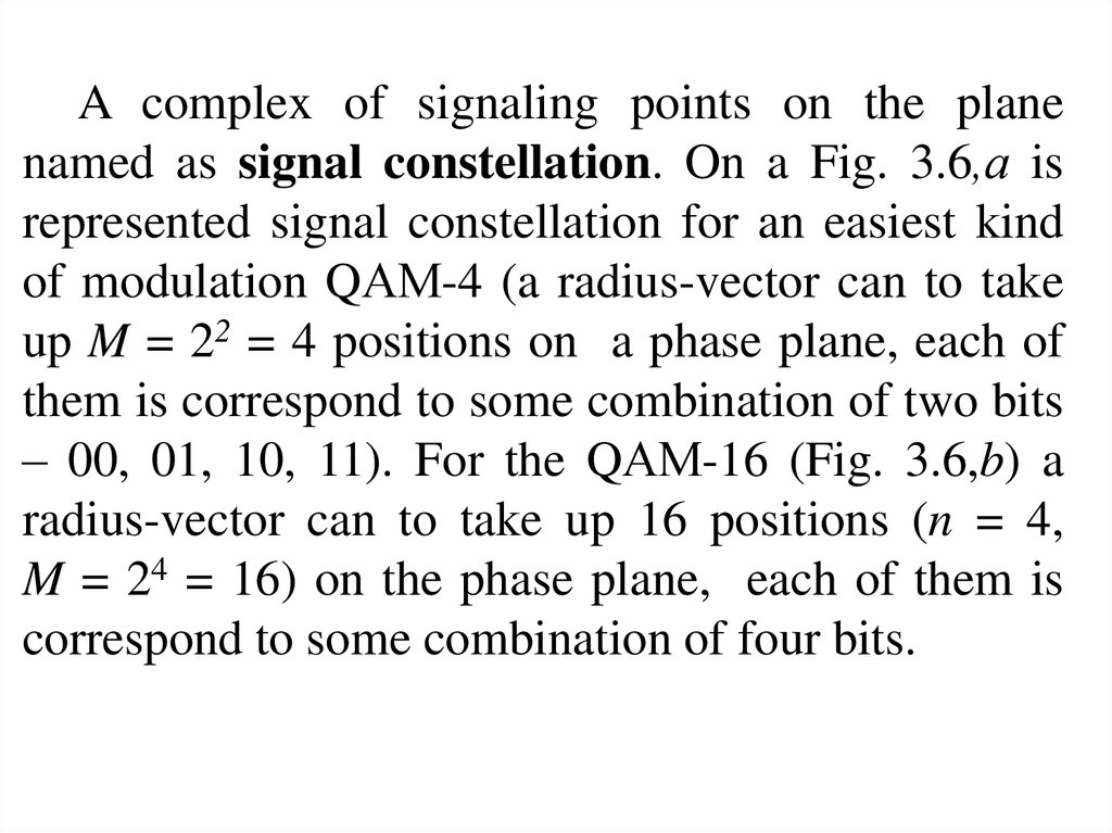
A complex of signaling points on the planenamed as signal constellation. On a Fig. 3.6,а is
represented signal constellation for an easiest kind
of modulation QАМ-4 (a radius-vector can to take
up M = 22 = 4 positions on a phase plane, each of
them is correspond to some combination of two bits
– 00, 01, 10, 11). For the QАМ-16 (Fig. 3.6,b) a
radius-vector can to take up 16 positions (n = 4,
M = 24 = 16) on the phase plane, each of them is
correspond to some combination of four bits.
20.
Advantages of QАМ:- narrow line spectrum, its location on frequency
axis is depend on choice of carrier;
- easy realization of FDC when multichannel
(parallel) transmission or when frequency division of
specters, that are trasmitted in the opposite direction
by one pair of signals in an asymmetrical DSL;
- simplicity of implementation, low price.
Disadvantages – high level of carrier power
(relative to the low levels of side bands) on the QАМ
spectrum results to energy transition on the neighbor
pears. It’s complicate a parallel work of several DSL
by one cable.
21.
CAP linear signal (APM without a carrier)On a SL of relatively large length CAP
modulation is applicable. This is the narrow-band
coding technology, insensitive to most of the
interference and enables collaboration and digital
transmission of telephone signals.
CAP technology is one of the latest advancements
modulation technology and microelectronics. CAP
signal diagram is similar to the QAM signal
diagram.
The carrier frequency is modulated by both
amplitude and phase, creating a code space with 64
or 128-th code states.
22.
On the transfer of the carrier frequency, whichdoes not contain the information, but has a
maximum power, "cut out" and is restored at a
reception microprocessor.
At CAP-64 6 bits of information are transmitted
at each time, that is 6 times higher than the code
2B1Q. At CAP-128 7 bits of information per clock
cycle are passed. This greatly reduces the signal
range that eliminates the sections of the spectrum
subject to distortions and interferences.
The spectral density of the CAP signal is
concentrated in the frequency range from 40 ... 260
kHz.
23.
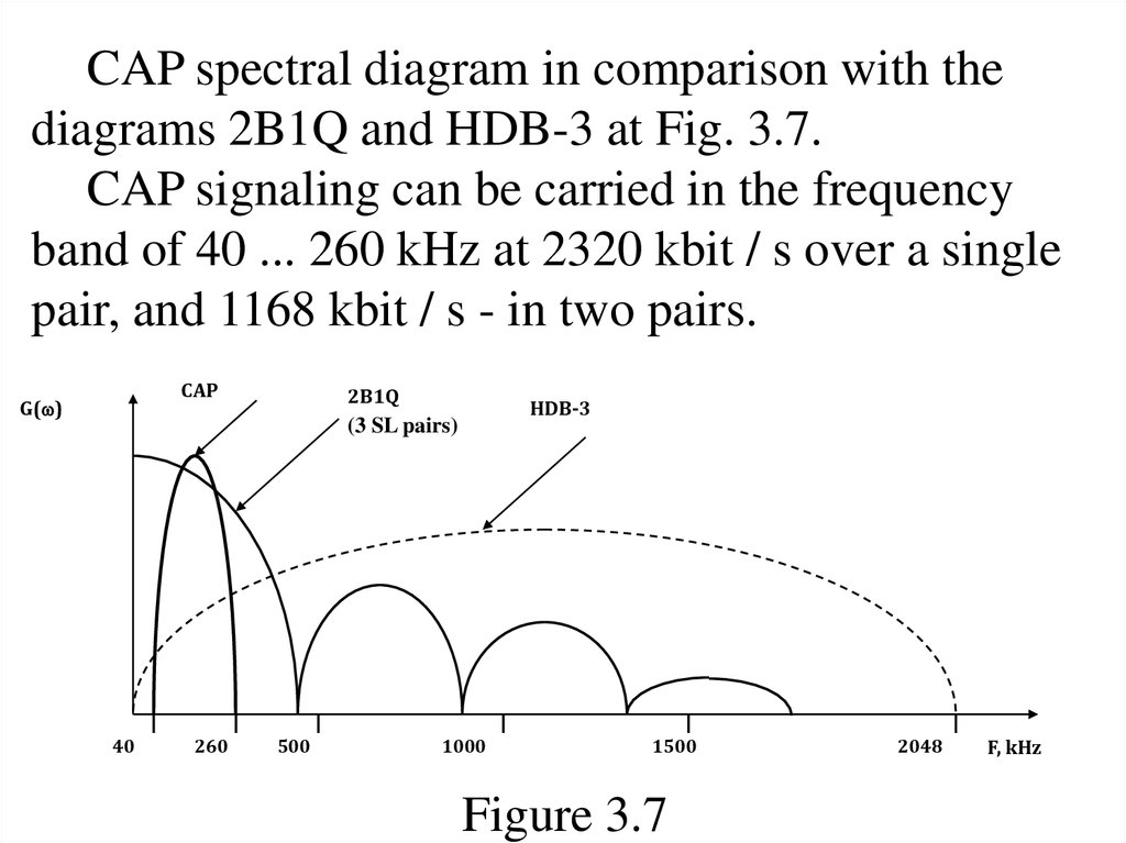
CAP spectral diagram in comparison with thediagrams 2B1Q and HDB-3 at Fig. 3.7.
CAP signaling can be carried in the frequency
band of 40 ... 260 kHz at 2320 kbit / s over a single
pair, and 1168 kbit / s - in two pairs.
CAP
G( )
2В1Q
HDB-3
(3 SL pairs)
40
260
500
1000
1500
Figure 3.7
2048
F, kHz
24.
Advantages of CAP.1) The range of the signal components of the
CAP does not exceed 260 kHz, and therefore can
be transmitted over greater distances than with a
signal code 2B1Q or HDB-3. Despreading leads to
gain on the transmission distance compared to
systems 2B1Q (two pairs) to 15 ... 20%, and for
systems operating one pair of - 30 ... 40%. Gain
compared with a DTS PCM-30 is 350 ... 400% on a
site without a regenerator for conductors with a
diameter of 0.4-0.5 mm.
25.
2) High noise immunity and insensitivity tothe group delay . Since there are no components in
the spectrum below 40 kHz and above 260 kHz , the
technology is insensitive to ATS HF crosstalk
(crosstalk radio interference ) and the impulse noise
as well as low distortion and crosstalk (start
powerful electric cars , electric ). Since the spectral
width is less than 200 kHz, the effect does not occur
due to the group delay time.
26.
3) The minimum level of interference, andinterference in the band VB channels. CAP
signal does not cause mutual influences and
interference in the spectrum of the phone signal ,
due to the absence in the spectrum of the
components below 4.0 kHz. This fact removes the
restrictions on the sharing of adjacent pairs of
cables for analog subscriber or interoffice
connections.
27.
4 ) Compatible with hardware compression ,running at adjacent pairs. Systems with CAP
may cause interferences in its operating range , but
the other channels are not affected . Consequently,
the possibility of parallel work on the same cable
equipment CAP and ATS. System with the same
code 2B1Q cause interferences on all channels
ATS workers to neighboring pairs.
5 ) CAP modulation is not sensitive to the
quality of the SL .
28.
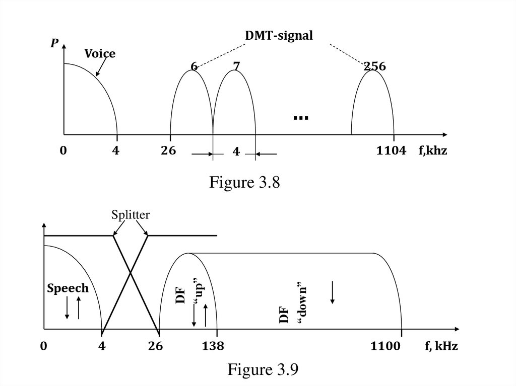
Modulation of DMT (Discrete MultiFrequency Modulation)DMT - is a modulation using a plurality of
subcarriers in the range 26 kHz ... 1,104 MHz (for
ASDL-technology). This range is divided into
256 subchannels. Each sub-channel has a width
of 4 kHz , Fig. 3.8. Each carrier is modulated
with the information signal on the basis of QAM quadrature amplitude modulation.
The number of bits of data transmitted in each
sub-channel depends on the link quality and
signal/noise ratio (S/N) in his band.
29.
DMT-signalР
Voice
6
7
256
…
0
4
26
1104 f,khz
4
Figure 3.8
Speech
0
4
26
DF
“down”
DF
“up”
Splitter
138
1100
Figure 3.9
f, kHz
30.
In each DMT subchannel there is an individualchoice of transmission rate as much as possible for
a given S/N. The values of the level of transmission
of information transmitted to the receiver are also
selected. Thus , DMT uses the principle of multifrequency division , but , moreover, allows to
exclude the transfer of highly noisy subchannels or
frequency band . Thus , DMT is adaptive
modulation. This method also solves the problem
of separating the speech and data signals , but is
more complex to implement than the CAP. DMT
standardized code in technology ADSL and VDSL.
31.
In DMT technology three streams of informationare actually passed (Fig.3.9): voice in the VBC, bidirectional data stream "up" (from the subscriber to
the network) and simplex data stream "down" (from
the network to the subscriber.)
The transfer is carried out over a two-wire line.
Separation of analog and digital signals is made
with a splitter (frequency splitter).
Separation of opposing streams of data is done by
the echo compensation method in the band 26 ... 138
kHz or by the frequency method.
32.
TC-PAM - Trellis Coded Pulse AmplitudeModulation
The recommendations ANSI, ETSI, ITU chosen
for simmetrical DSL- making new technology TCPAM ( HDSL- 2 standard , G.SHDSL).
Benefits of TC- PAM technology are like 2B1Q
its simplicity and CAP modulation its effectiveness.
TC- PAM has the best performance for
electromagnetic compatibility ( EMC). The essence
of the encoding method is to increase the number of
code levels or distances from 4 to 16 and the
application of a special error correction mechanism.
33.
Coding technologies TC- PAM (for example,PAM -16) transmits one symbol of 3 bits of useful
information and fourth additional bit for error
protection coding.
TC- PAM technology is not anything new, it's
PAM technology , as well as coding 2B1Q. But the
use of lattice or trellis codes has reduced due to the
redundancy introduced into the transmitted data ,
the probability of error when winning a 5 dB
immunity. To decode the TC - PAM modulation the
Vitterbi algorithm is used . TC- PAM technology is
accepted by ITU as a single Symmetrical DSLstandard for all developers (GSHDSL).
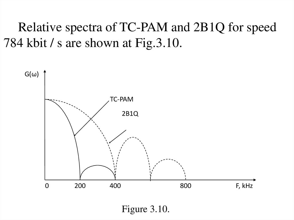
34.
Relative spectra of TC-PAM and 2B1Q for speed784 kbit / s are shown at Fig.3.10.
G(ω)
TC-PAM
2B1Q
0
200
400
800
Figure 3.10.
F, kHz
35.
Comparison of the energy spectra shows that inparallel operation xDSL systems crosstalk caused
technology TC- PAM will be less interference
coding 2B1Q, ie at a downstream ADSL crosstalk is
absent, and at upward is negligible.
For CAP technology, the presence of c
connection of high power signal is transmitted in
the frequency bands of 10 to 40 kHz and 150 - 200
kHz and large electromagnetic effects , parallel use
of other xDSL- technologies is almost impossible.
36.
Experimentally confirmed that a linear encodingprovides TC- PAM compared to technology 2B1Q
greater by 30 - 45% of the data rate on the lines of
equal length and at most 15 - 20% range with the
same transmission speed.
Thus , data is transferred at high speed duplex on
the 1st pair of wires at a significant level of
interference.
37.
Control test. 1-st attestationName and surname of student
_______________________________
Task: M is equal to the last digit of the test book.
M = _____
The transmission rate of information flow
B= 1000+(M+1)*300 kbit/s
Draw a linear signal spectral diagram if 2B1Q code is
used.
Solution: