


 Программное обеспечение
 Механика
Похожие презентации:


VHMS technology as monitoring condition’s instrument aid
1.
VHMS TECHNOLOGY AS MONITORINGCONDITION’S INSTRUMENT AID
1
2.
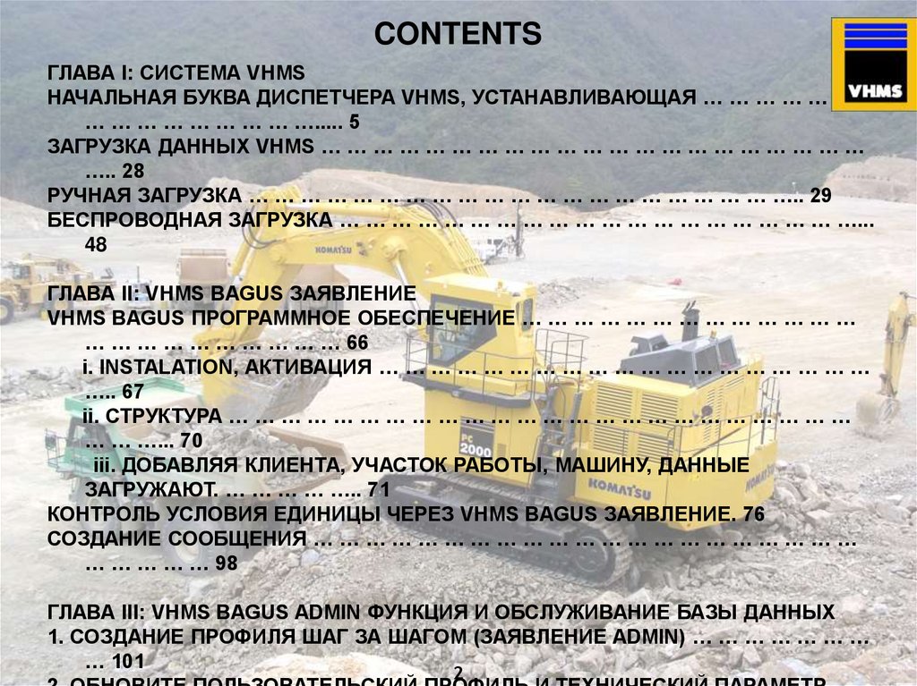
CONTENTSГЛАВА I: СИСТЕМА VHMS
НАЧАЛЬНАЯ БУКВА ДИСПЕТЧЕРА VHMS, УСТАНАВЛИВАЮЩАЯ … … … … … …
… … … … … … … … …..... 5
ЗАГРУЗКА ДАННЫХ VHMS … … … … … … … … … … … … … … … … … … … … …
….. 28
РУЧНАЯ ЗАГРУЗКА … … … … … … … … … … … … … … … … … … … … ….. 29
БЕСПРОВОДНАЯ ЗАГРУЗКА … … … … … … … … … … … … … … … … … … … …...
48
ГЛАВА II: VHMS BAGUS ЗАЯВЛЕНИЕ
VHMS BAGUS ПРОГРАММНОЕ ОБЕСПЕЧЕНИЕ … … … … … … … … … … … … …
… … … … … … … … … … 66
i. INSTALATION, АКТИВАЦИЯ … … … … … … … … … … … … … … … … … … …
….. 67
ii. СТРУКТУРА … … … … … … … … … … … … … … … … … … … … … … … …
… … …... 70
iii. ДОБАВЛЯЯ КЛИЕНТА, УЧАСТОК РАБОТЫ, МАШИНУ, ДАННЫЕ
ЗАГРУЖАЮТ. … … … … ….. 71
КОНТРОЛЬ УСЛОВИЯ ЕДИНИЦЫ ЧЕРЕЗ VHMS BAGUS ЗАЯВЛЕНИЕ. 76
СОЗДАНИЕ СООБЩЕНИЯ … … … … … … … … … … … … … … … … … … … … …
… … … … … 98
ГЛАВА III: VHMS BAGUS ADMIN ФУНКЦИЯ И ОБСЛУЖИВАНИЕ БАЗЫ ДАННЫХ
1. СОЗДАНИЕ ПРОФИЛЯ ШАГ ЗА ШАГОМ (ЗАЯВЛЕНИЕ ADMIN) … … … … … … …
… 101
2
3.
CHAPTER IVHMS SYSTEM
3
4.
НАЧАЛЬНАЯ БУКВА ДИСПЕТЧЕРА VHMS,УСТАНАВЛИВАЮЩАЯ ДЛЯ ВСЕХ МАШИН
С VHMS
4
5.
УРЕГУЛИРОВАНИЕ НАЧАЛЬНОЙБУКВЫ
ДИСПЕТЧЕРА VHMS
General Objectives
:
Настраивать Машинную Идентификацию (Машина S/N, Двигатель S/N,
Передача S/N) в диспетчера VHMS и к часовому поясу установки,
приспособленному к местоположению единицы.
Начальное Урегулирование выполнено:
Для Новой Поставки Единицы, какое урегулирование Диспетчера VHMS не
было выполнено.
Когда Удаляют и Устанавливают Двигатель и или Передача выполнена,
где регистрационный номер компонента изменился.
Когда единица перемещена в другое местоположение с другим Часовым
поясом.
Изменяя Диспетчера VHMS, в котором данные от старого диспетчера
VHMS перемещены в нового диспетчера.
5
6.
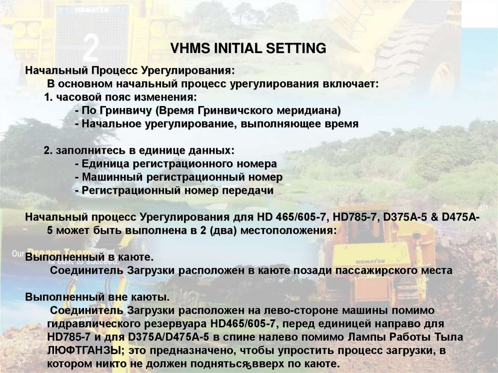
VHMS INITIAL SETTINGНачальный Процесс Урегулирования:
В основном начальный процесс урегулирования включает:
1. часовой пояс изменения:
- По Гринвичу (Время Гринвичского меридиана)
- Начальное урегулирование, выполняющее время
2. заполнитесь в единице данных:
- Единица регистрационного номера
- Машинный регистрационный номер
- Регистрационный номер передачи
Начальный процесс Урегулирования для HD 465/605-7, HD785-7, D375A-5 & D475A5 может быть выполнена в 2 (два) местоположения:
Выполненный в каюте.
Соединитель Загрузки расположен в каюте позади пассажирского места
Выполненный вне каюты.
Соединитель Загрузки расположен на лево-стороне машины помимо
гидравлического резервуара HD465/605-7, перед единицей направо для
HD785-7 и для D375A/D475A-5 в спине налево помимо Лампы Работы Тыла
ЛЮФТГАНЗЫ; это предназначено, чтобы упростить процесс загрузки, в
котором никто не должен подняться6вверх по каюте.
7.
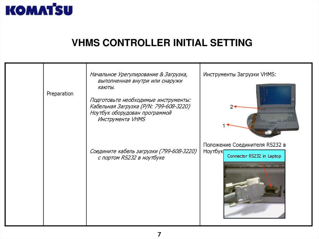
VHMS CONTROLLER INITIAL SETTINGPreparation
Начальное Урегулирование & Загрузка,
выполненная внутри или снаружи
каюты.
Инструменты Загрузки VHMS:
Подготовьте необходимые инструменты:
Кабельная Загрузка (P/N: 799-608-3220)
Ноутбук оборудован программой
Инструмента VHMS
2
1
Соедините кабель загрузки (799-608-3220)
с портом RS232 в ноутбуке
7
Положение Соединителя RS232 в
Ноутбуке:
Connector RS232 in Laptop
8.
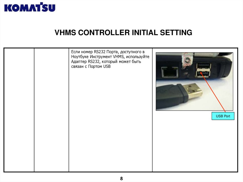
VHMS CONTROLLER INITIAL SETTINGЕсли номер RS232 Порта, доступного в
Ноутбуке Инструмент VHMS, используйте
Адаптер RS232, который может быть
связан с Портом USB
USB Port
8
9.
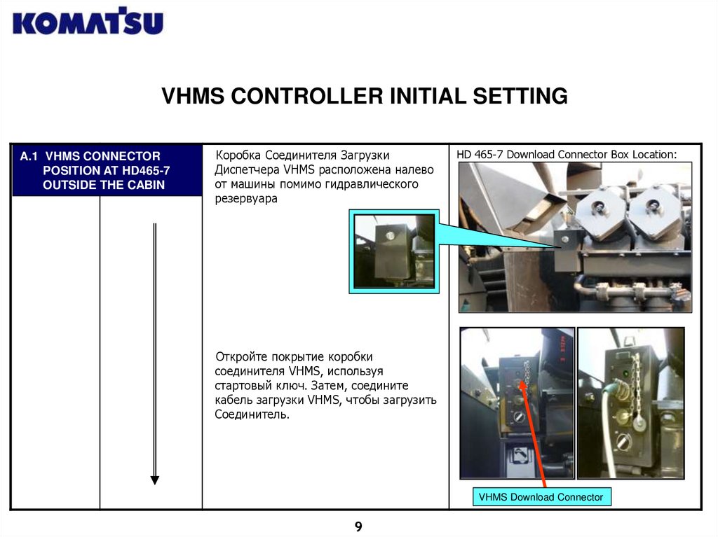
VHMS CONTROLLER INITIAL SETTINGA.1 VHMS CONNECTOR
POSITION AT HD465-7
OUTSIDE THE CABIN
Коробка Соединителя Загрузки
Диспетчера VHMS расположена налево
от машины помимо гидравлического
резервуара
HD 465-7 Download Connector Box Location:
Откройте покрытие коробки
соединителя VHMS, используя
стартовый ключ. Затем, соедините
кабель загрузки VHMS, чтобы загрузить
Соединитель.
VHMS Download Connector
9
10.
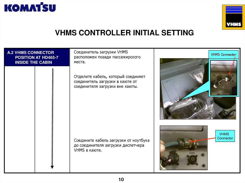
VHMS CONTROLLER INITIAL SETTINGA.2 VHMS CONNECTOR
POSITION AT HD465-7
INSIDE THE CABIN
Соединитель загрузки VHMS
расположен позади пассажирского
места.
VHMS Connector
Отделите кабель, который соединяет
соединитель загрузки в каюте от
соединителя загрузки вне каюты.
Соедините кабель загрузки от ноутбука
до соединителя загрузки диспетчера
VHMS в каюте.
10
VHMS
Connector
11.
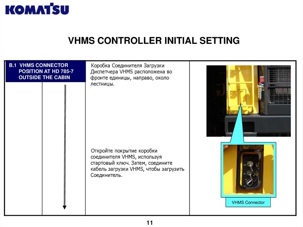
VHMS CONTROLLER INITIAL SETTINGB.1 VHMS CONNECTOR
POSITION AT HD 785-7
OUTSIDE THE CABIN
Коробка Соединителя Загрузки
Диспетчера VHMS расположена во
фронте единицы, направо, около
лестницы.
Откройте покрытие коробки
соединителя VHMS, используя
стартовый ключ. Затем, соедините
кабель загрузки VHMS, чтобы загрузить
Соединитель.
VHMS Connector
11
12.
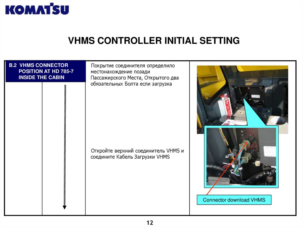
VHMS CONTROLLER INITIAL SETTINGB.2 VHMS CONNECTOR
POSITION AT HD 785-7
INSIDE THE CABIN
Покрытие соединителя определило
местонахождение позади
Пассажирского Места, Открытого два
обязательных Болта если загрузка
Откройте верхний соединитель VHMS и
соедините Кабель Загрузки VHMS
Connector download VHMS
12
13.
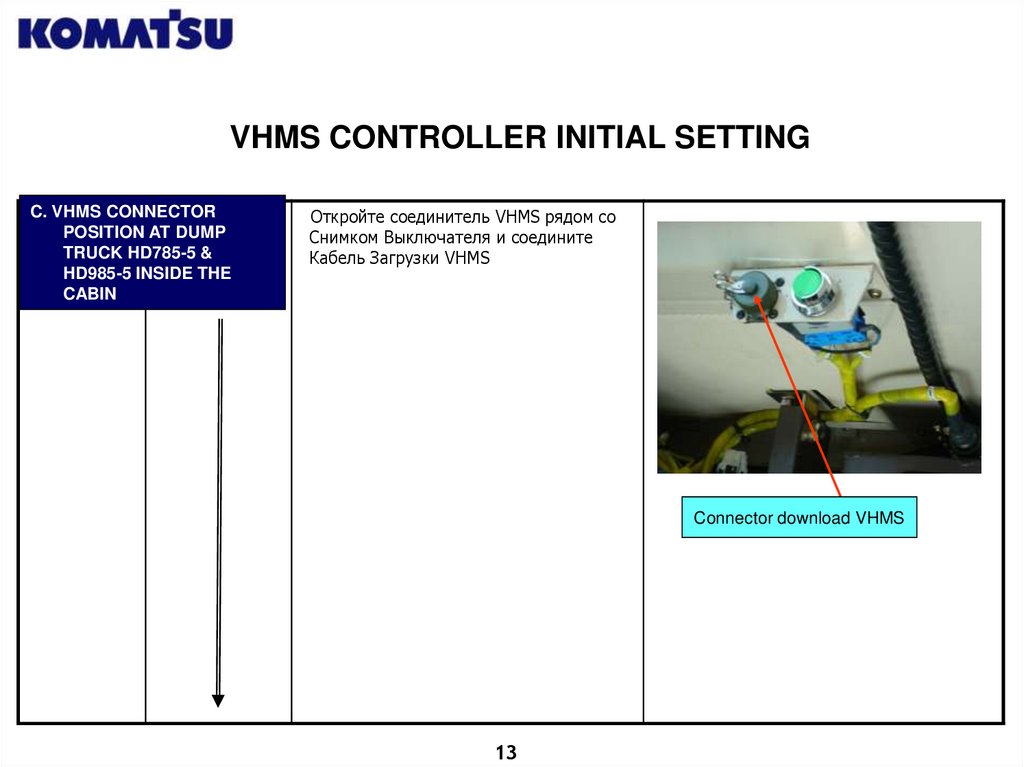
VHMS CONTROLLER INITIAL SETTINGC. VHMS CONNECTOR
POSITION AT DUMP
TRUCK HD785-5 &
HD985-5 INSIDE THE
CABIN
Откройте соединитель VHMS рядом со
Снимком Выключателя и соедините
Кабель Загрузки VHMS
Connector download VHMS
13
14.
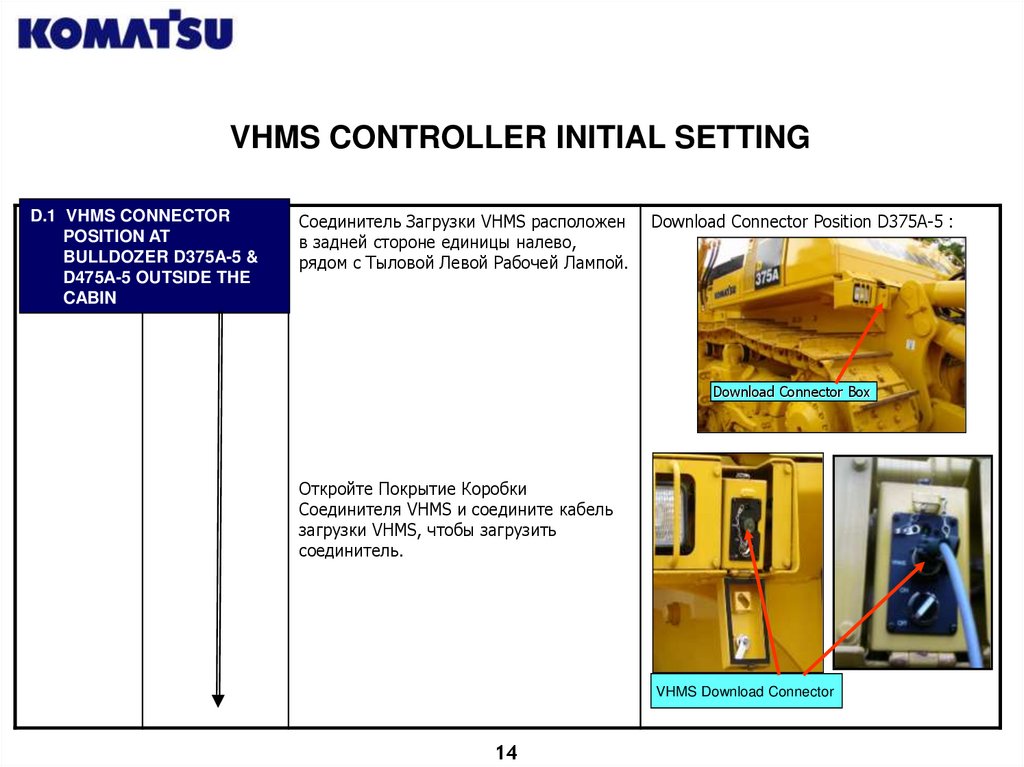
VHMS CONTROLLER INITIAL SETTINGD.1 VHMS CONNECTOR
POSITION AT
BULLDOZER D375A-5 &
D475A-5 OUTSIDE THE
CABIN
Соединитель Загрузки VHMS расположен
в задней стороне единицы налево,
рядом с Тыловой Левой Рабочей Лампой.
Download Connector Position D375A-5 :
Download Connector Box
Откройте Покрытие Коробки
Соединителя VHMS и соедините кабель
загрузки VHMS, чтобы загрузить
соединитель.
VHMS Download Connector
14
15.
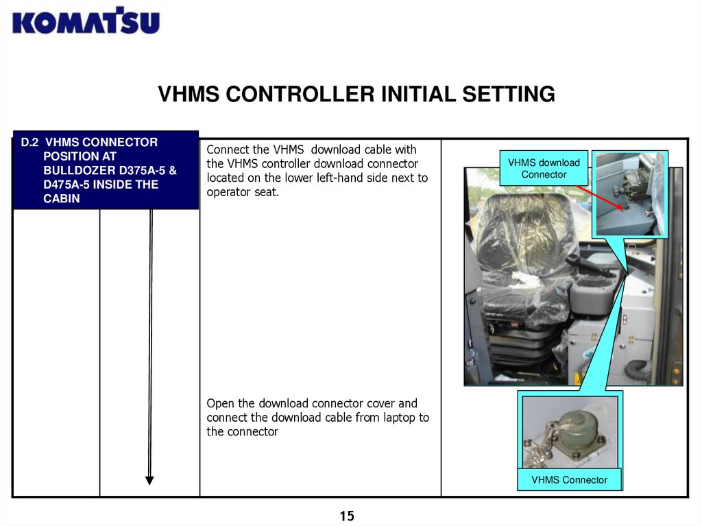
VHMS CONTROLLER INITIAL SETTINGD.2 VHMS CONNECTOR
POSITION AT
BULLDOZER D375A-5 &
D475A-5 INSIDE THE
CABIN
Connect the VHMS download cable with
the VHMS controller download connector
located on the lower left-hand side next to
operator seat.
VHMS download
Connector
Open the download connector cover and
connect the download cable from laptop to
the connector
VHMS Connector
15
16.
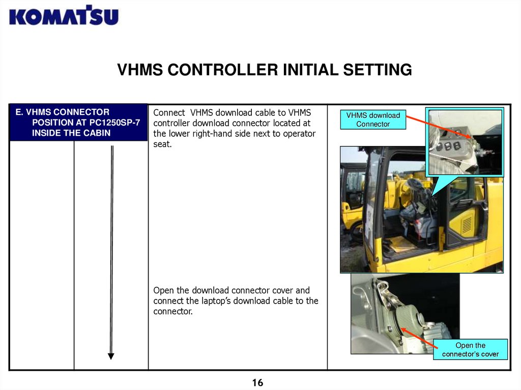
VHMS CONTROLLER INITIAL SETTINGE. VHMS CONNECTOR
POSITION AT PC1250SP-7
INSIDE THE CABIN
Connect VHMS download cable to VHMS
controller download connector located at
the lower right-hand side next to operator
seat.
VHMS download
Connector
Open the download connector cover and
connect the laptop’s download cable to the
connector.
Open the
connector’s cover
16
17.
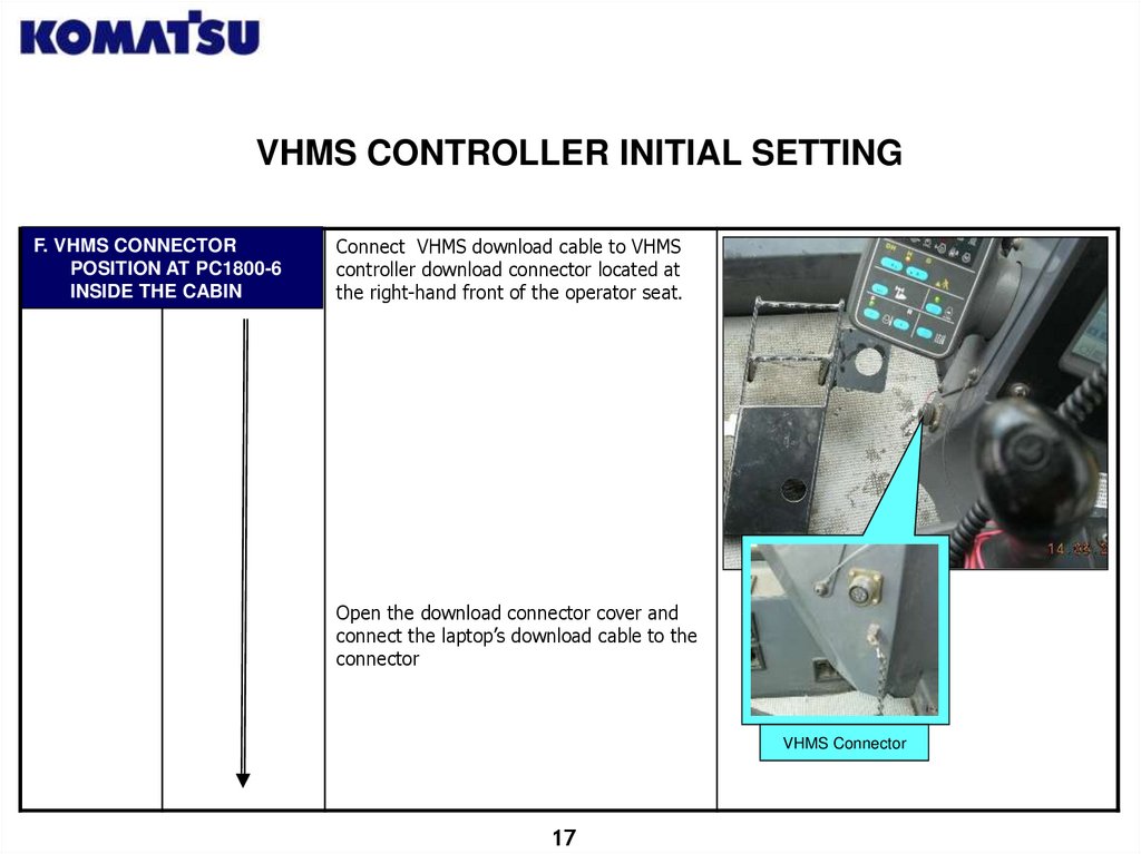
VHMS CONTROLLER INITIAL SETTINGF. VHMS CONNECTOR
POSITION AT PC1800-6
INSIDE THE CABIN
Connect VHMS download cable to VHMS
controller download connector located at
the right-hand front of the operator seat.
Open the download connector cover and
connect the laptop’s download cable to the
connector
VHMS Connector
17
18.
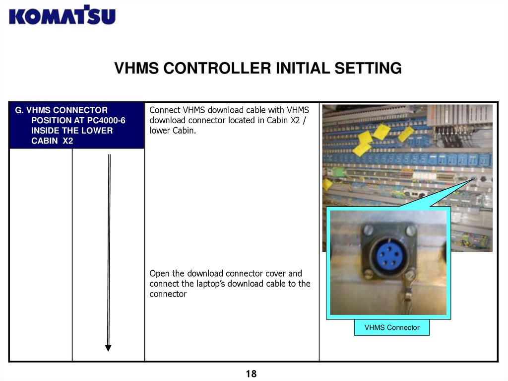
VHMS CONTROLLER INITIAL SETTINGG. VHMS CONNECTOR
POSITION AT PC4000-6
INSIDE THE LOWER
CABIN X2
Connect VHMS download cable with VHMS
download connector located in Cabin X2 /
lower Cabin.
Open the download connector cover and
connect the laptop’s download cable to the
connector
VHMS Connector
18
19.
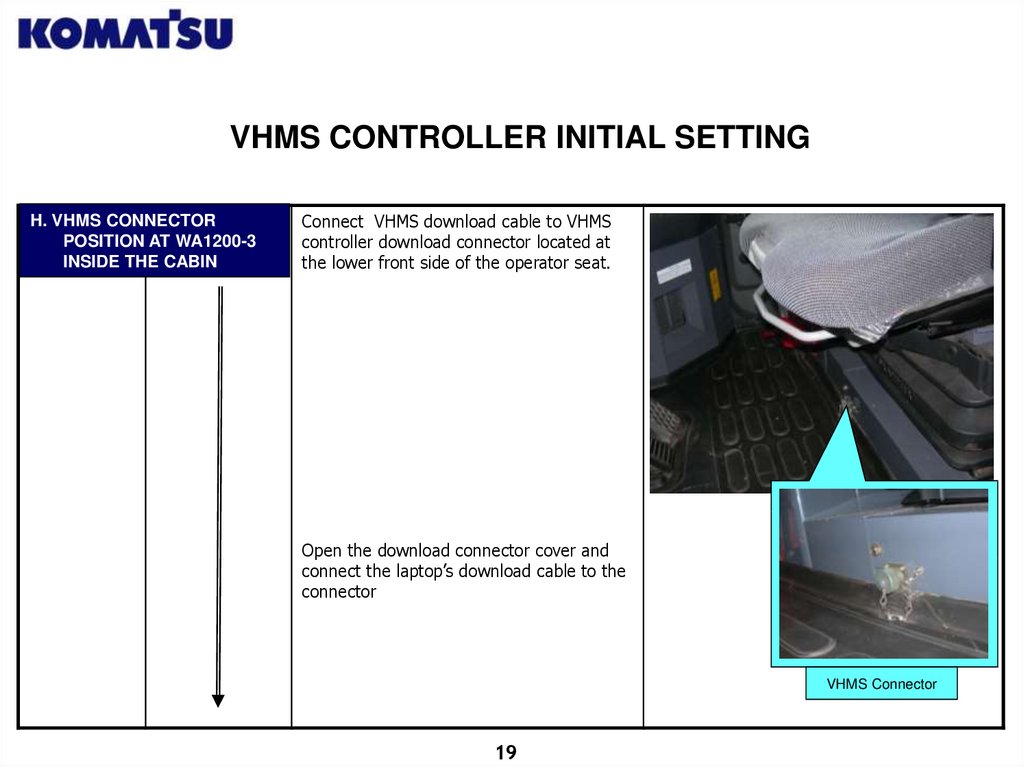
VHMS CONTROLLER INITIAL SETTINGH. VHMS CONNECTOR
POSITION AT WA1200-3
INSIDE THE CABIN
Connect VHMS download cable to VHMS
controller download connector located at
the lower front side of the operator seat.
Open the download connector cover and
connect the laptop’s download cable to the
connector
VHMS Connector
19
20.
VHMS CONTROLLER INITIAL SETTING<1>
Turn off
Engine
<2>
Starting key
switch /
Selector
Switch ON
<1>
Start VHMS
Initial Setting
Tools
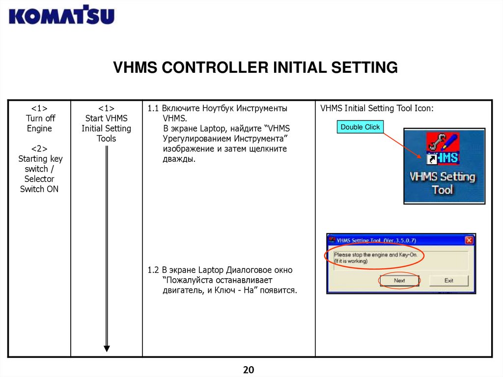
1.1 Включите Ноутбук Инструменты
VHMS.
В экране Laptop, найдите “VHMS
Урегулированием Инструмента”
изображение и затем щелкните
дважды.
1.2 В экране Laptop Диалоговое окно
“Пожалуйста останавливает
двигатель, и Ключ - На” появится.
20
VHMS Initial Setting Tool Icon:
Double Click
21.
VHMS CONTROLLER INITIAL SETTING<2>
Select the
Process to
perform
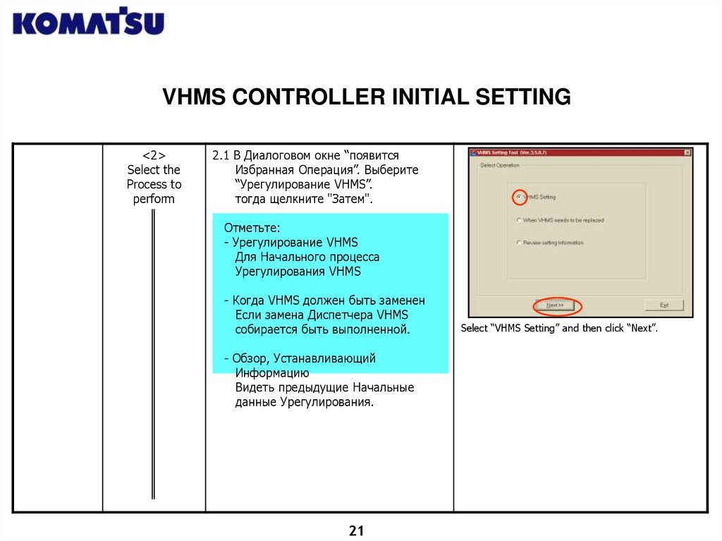
2.1 В Диалоговом окне “появится
Избранная Операция”. Выберите
“Урегулирование VHMS”.
тогда щелкните "Затем".
Отметьте:
- Урегулирование VHMS
Для Начального процесса
Урегулирования VHMS
- Когда VHMS должен быть заменен
Если замена Диспетчера VHMS
собирается быть выполненной.
- Обзор, Устанавливающий
Информацию
Видеть предыдущие Начальные
данные Урегулирования.
21
Select “VHMS Setting” and then click “Next”.
22.
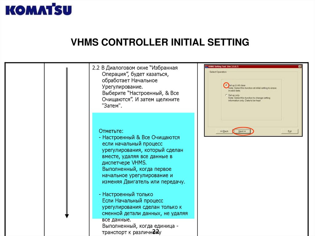
VHMS CONTROLLER INITIAL SETTING2.2 В Диалоговом окне “Избранная
Операция”, будет казаться,
обработает Начальное
Урегулирование.
Выберите “Настроенный, & Все
Очищаются”. И затем щелкните
"Затем".
Отметьте:
- Настроенный & Все Очищаются
если начальный процесс
урегулирования, который сделан
вместе, удаляя все данные в
диспетчере VHMS.
Выполненный, когда первое
начальное урегулирование и
изменяя Двигатель или передачу.
- Настроенный только
Если Начальный процесс
урегулирования сделан только к
сменной детали данных, не удаляя
все данные.
Выполненный, когда единица 22
транспорт к различному
23.
VHMS CONTROLLER INITIAL SETTING<3>
Check Unit Data
Completeness
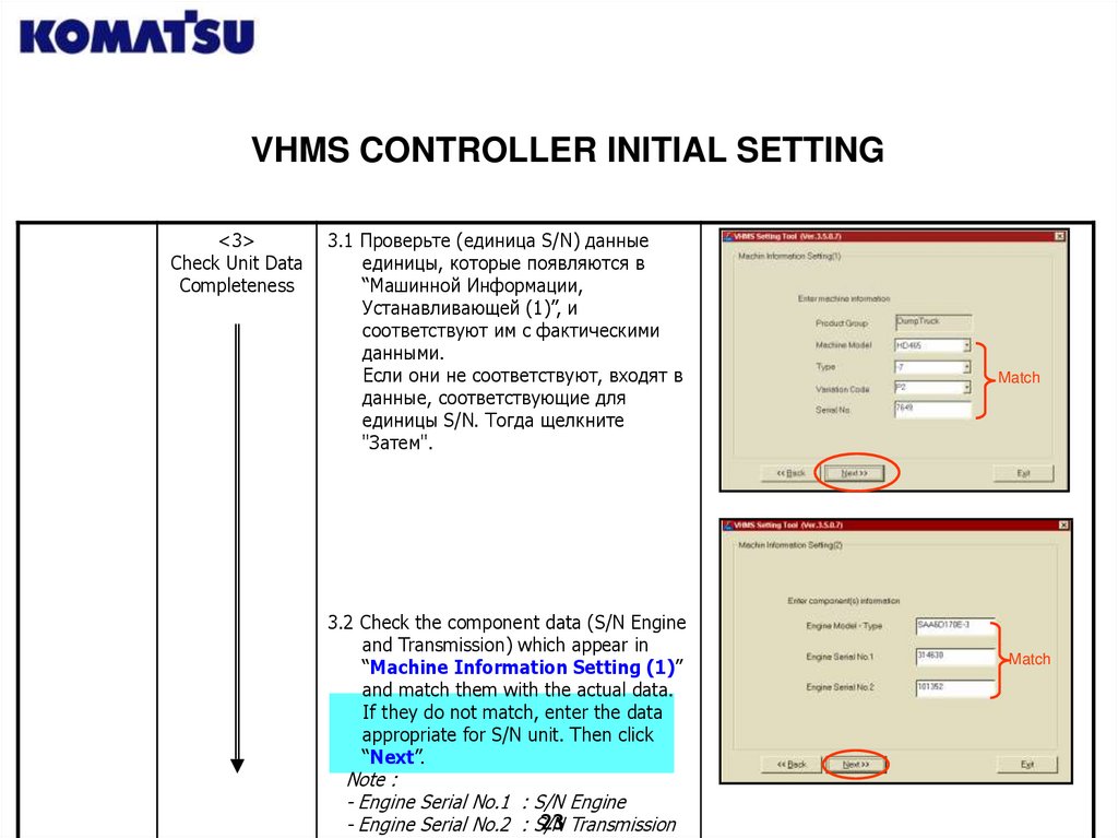
3.1 Проверьте (единица S/N) данные
единицы, которые появляются в
“Машинной Информации,
Устанавливающей (1)”, и
соответствуют им с фактическими
данными.
Если они не соответствуют, входят в
данные, соответствующие для
единицы S/N. Тогда щелкните
"Затем".
3.2 Check the component data (S/N Engine
and Transmission) which appear in
“Machine Information Setting (1)”
and match them with the actual data.
If they do not match, enter the data
appropriate for S/N unit. Then click
“Next”.
Note :
- Engine Serial No.1 : S/N Engine
23 Transmission
- Engine Serial No.2 : S/N
Match
Match
24.
VHMS CONTROLLER INITIAL SETTING<4>
Setting Date
and Time Initial
Setting
4. In the Dialog Box “Date & Time
Setting” will appear
- Set “Time Zone” by clicking ” “ and
select “GMT + 08.00” (example for
Central Indonesian Time Zone).
- Set “Date (MM/DD/YYYY)” to suit
the local date when setting.
- Set “Time (Hour:Minute:Second)” to
suit the local time when setting.
If the data are already appropriate,
click “Next” for further process.
Time Zone Setting depends on the location where the
Unit will operate.
Time Zone :
- GMT + 07.00 : for Western Indonesia.
- GMT + 08.00 : for Central Indonesia.
- GMT + 09.00 : for Eastern Indonesia.
24
25.
VHMS CONTROLLER INITIAL SETTING<5>
Set the GCC
(Gateway
Control Center)
<6>
Check Initial
Setting Data
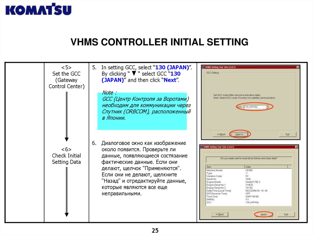
5. In setting GCC, select “130 (JAPAN)”.
By clicking “
“ select GCC “130
(JAPAN)” and then click “Next”.
Note :
GCC (Центр Контроля за Воротами)
необходим для коммуникации через
Спутник (ORBCOM), расположенный
в Японии.
6. Диалоговое окно как изображение
около появится. Проверьте ли
данные, появляющиеся состязание
фактические данные. Если они
делают, щелчок "Применяются".
Если они не делают, щелкните
"Назад" и отредактируйте данные,
которые являются все еще
неправильными.
25
26.
VHMS CONTROLLER INITIAL SETTING<7>
Confirming
Download
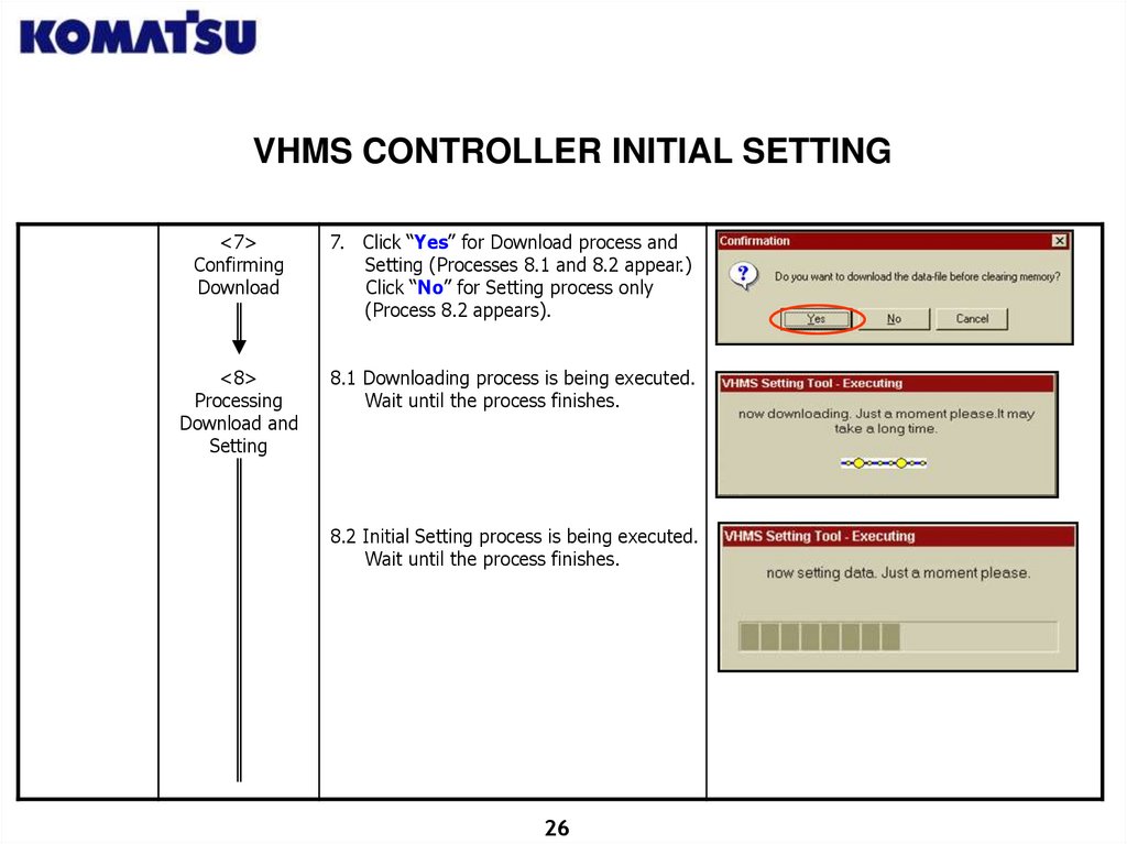
7. Click “Yes” for Download process and
Setting (Processes 8.1 and 8.2 appear.)
Click “No” for Setting process only
(Process 8.2 appears).
<8>
Processing
Download and
Setting
8.1 Downloading process is being executed.
Wait until the process finishes.
8.2 Initial Setting process is being executed.
Wait until the process finishes.
26
27.
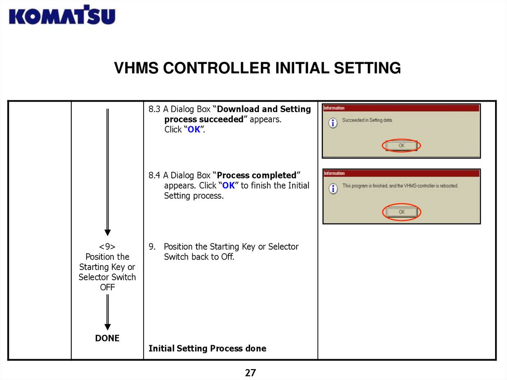
VHMS CONTROLLER INITIAL SETTING8.3 A Dialog Box “Download and Setting
process succeeded” appears.
Click “OK”.
8.4 A Dialog Box “Process completed”
appears. Click “OK” to finish the Initial
Setting process.
<9>
Position the
Starting Key or
Selector Switch
OFF
DONE
9. Position the Starting Key or Selector
Switch back to Off.
Initial Setting Process done
27
28.
VHMS DATA MANUAL DOWNLOAD28
29.
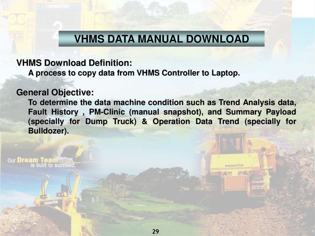
VHMS DATA MANUAL DOWNLOADVHMS Download Definition:
A process to copy data from VHMS Controller to Laptop.
General Objective:
To determine the data machine condition such as Trend Analysis data,
Fault History , PM-Clinic (manual snapshot), and Summary Payload
(specially for Dump Truck) & Operation Data Trend (specially for
Bulldozer).
29
30.
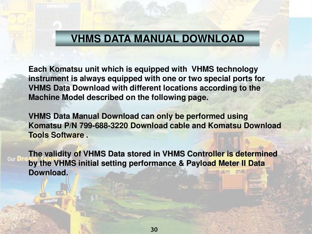
VHMS DATA MANUAL DOWNLOADEach Komatsu unit which is equipped with VHMS technology
instrument is always equipped with one or two special ports for
VHMS Data Download with different locations according to the
Machine Model described on the following page.
VHMS Data Manual Download can only be performed using
Komatsu P/N 799-688-3220 Download cable and Komatsu Download
Tools Software .
The validity of VHMS Data stored in VHMS Controller is determined
by the VHMS initial setting performance & Payload Meter II Data
Download.
30
31.
VHMS DATA MANUAL DOWNLOADSPECIAL
ATTENTION
WORK STEPS
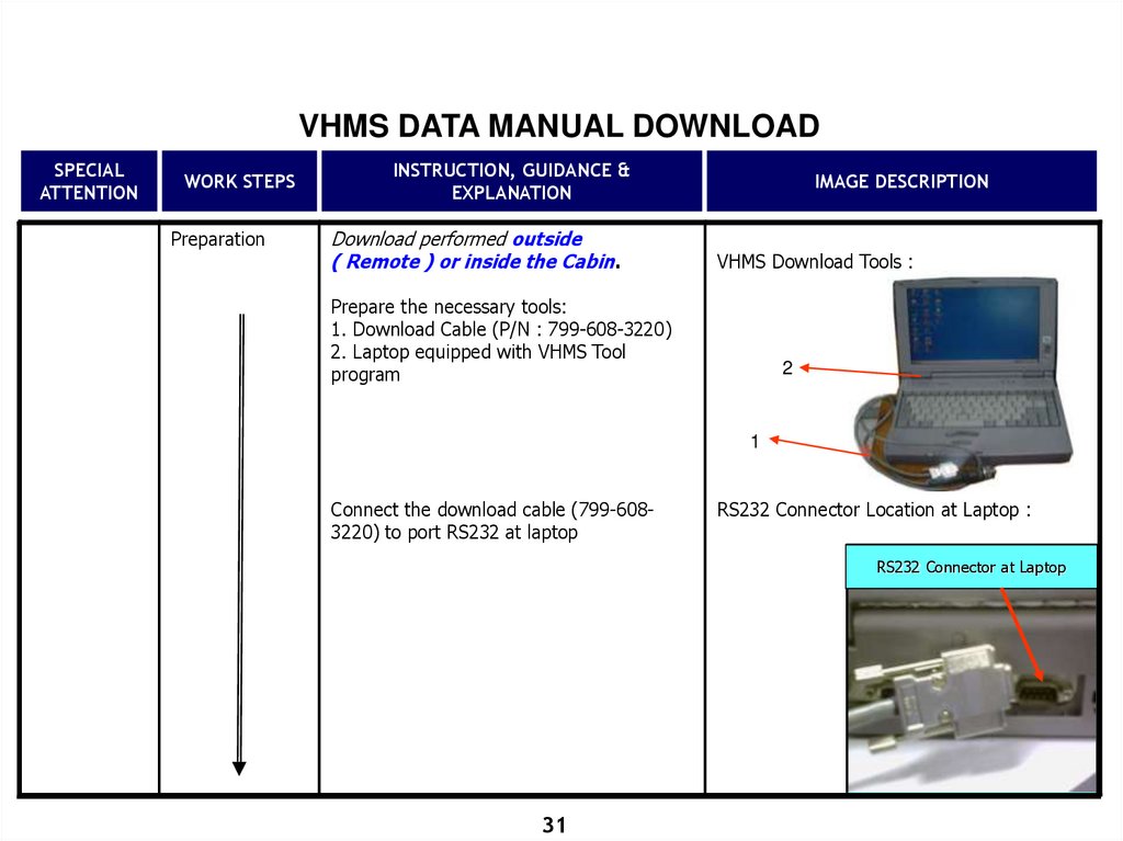
Preparation
INSTRUCTION, GUIDANCE &
EXPLANATION
Download performed outside
( Remote ) or inside the Cabin.
IMAGE DESCRIPTION
VHMS Download Tools :
Prepare the necessary tools:
1. Download Cable (P/N : 799-608-3220)
2. Laptop equipped with VHMS Tool
program
2
1
Connect the download cable (799-6083220) to port RS232 at laptop
RS232 Connector Location at Laptop :
RS232 Connector at Laptop
31
32.
VHMS DATA MANUAL DOWNLOADSPECIAL
ATTENTION
WORK STEPS
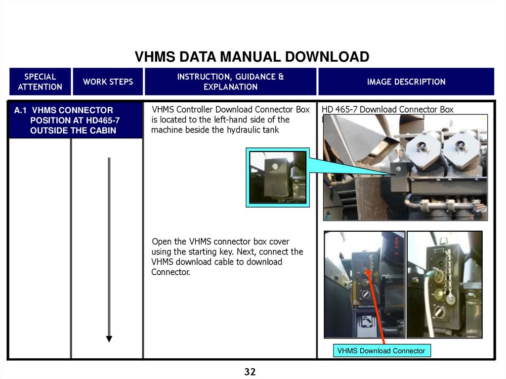
A.1 VHMS CONNECTOR
POSITION AT HD465-7
OUTSIDE THE CABIN
INSTRUCTION, GUIDANCE &
EXPLANATION
VHMS Controller Download Connector Box
is located to the left-hand side of the
machine beside the hydraulic tank
IMAGE DESCRIPTION
HD 465-7 Download Connector Box
Location:
Open the VHMS connector box cover
using the starting key. Next, connect the
VHMS download cable to download
Connector.
VHMS Download Connector
32
33.
VHMS DATA MANUAL DOWNLOADSPECIAL
ATTENTION
WORK STEPS
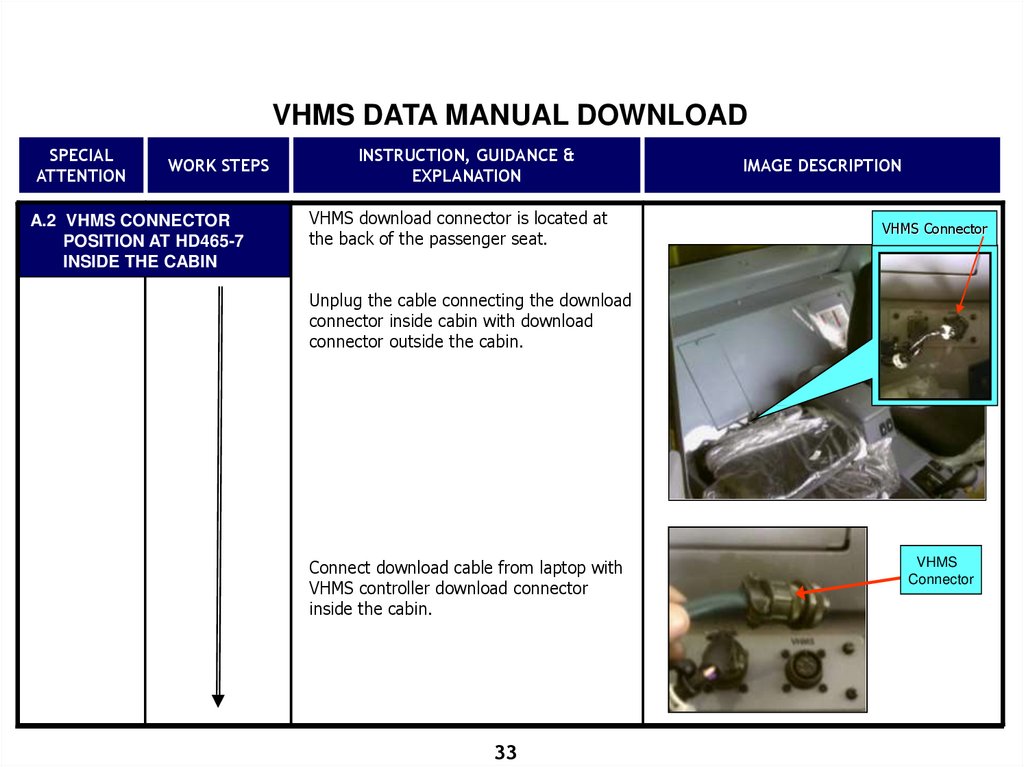
A.2 VHMS CONNECTOR
POSITION AT HD465-7
INSIDE THE CABIN
INSTRUCTION, GUIDANCE &
EXPLANATION
VHMS download connector is located at
the back of the passenger seat.
IMAGE DESCRIPTION
VHMS Connector
Unplug the cable connecting the download
connector inside cabin with download
connector outside the cabin.
Connect download cable from laptop with
VHMS controller download connector
inside the cabin.
33
VHMS
Connector
34.
VHMS DATA MANUAL DOWNLOADSPECIAL
ATTENTION
WORK STEPS
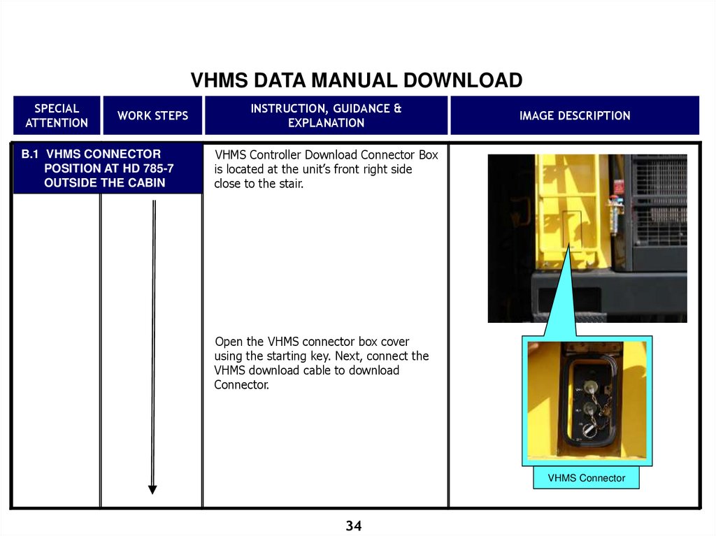
B.1 VHMS CONNECTOR
POSITION AT HD 785-7
OUTSIDE THE CABIN
INSTRUCTION, GUIDANCE &
EXPLANATION
IMAGE DESCRIPTION
VHMS Controller Download Connector Box
is located at the unit’s front right side
close to the stair.
Open the VHMS connector box cover
using the starting key. Next, connect the
VHMS download cable to download
Connector.
VHMS Connector
34
35.
VHMS DATA MANUAL DOWNLOADSPECIAL
ATTENTION
WORK STEPS
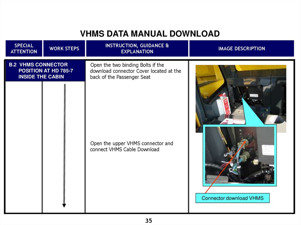
B.2 VHMS CONNECTOR
POSITION AT HD 785-7
INSIDE THE CABIN
INSTRUCTION, GUIDANCE &
EXPLANATION
IMAGE DESCRIPTION
Open the two binding Bolts if the
download connector Cover located at the
back of the Passenger Seat
Open the upper VHMS connector and
connect VHMS Cable Download
Connector download VHMS
35
36.
MANUAL DOWNLOAD VHMS DATASPECIAL
ATTENTION
WORK STEPS
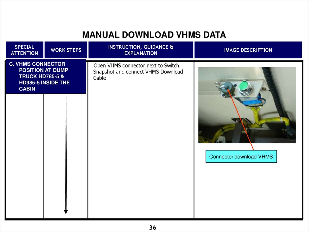
C. VHMS CONNECTOR
POSITION AT DUMP
TRUCK HD785-5 &
HD985-5 INSIDE THE
CABIN
INSTRUCTION, GUIDANCE &
EXPLANATION
IMAGE DESCRIPTION
Open VHMS connector next to Switch
Snapshot and connect VHMS Download
Cable
Connector download VHMS
36
37.
VHMS DATA MANUAL DOWNLOADSPECIAL
ATTENTION
WORK STEPS
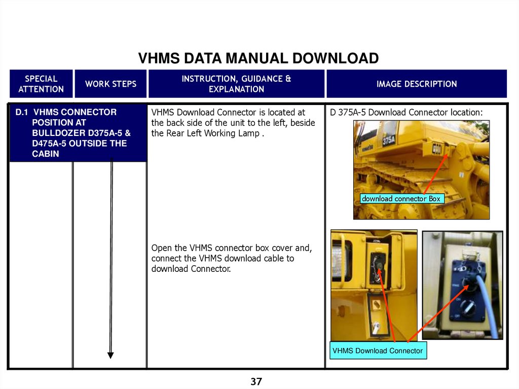
D.1 VHMS CONNECTOR
POSITION AT
BULLDOZER D375A-5 &
D475A-5 OUTSIDE THE
CABIN
INSTRUCTION, GUIDANCE &
EXPLANATION
VHMS Download Connector is located at
the back side of the unit to the left, beside
the Rear Left Working Lamp .
IMAGE DESCRIPTION
D 375A-5 Download Connector location:
download connector Box
Open the VHMS connector box cover and,
connect the VHMS download cable to
download Connector.
VHMS Download Connector
37
38.
VHMS DATA MANUAL DOWNLOADSPECIAL
ATTENTION
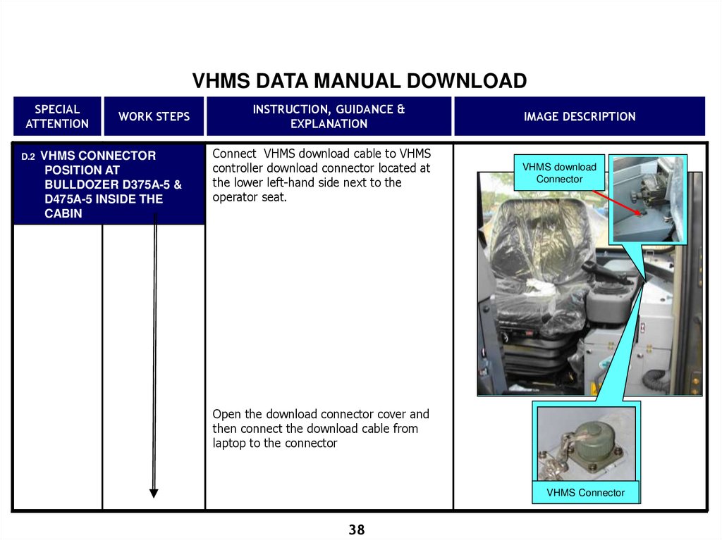
D.2
WORK STEPS
VHMS CONNECTOR
POSITION AT
BULLDOZER D375A-5 &
D475A-5 INSIDE THE
CABIN
INSTRUCTION, GUIDANCE &
EXPLANATION
Connect VHMS download cable to VHMS
controller download connector located at
the lower left-hand side next to the
operator seat.
IMAGE DESCRIPTION
VHMS download
Connector
Open the download connector cover and
then connect the download cable from
laptop to the connector
VHMS Connector
38
39.
VHMS DATA MANUAL DOWNLOADSPECIAL
ATTENTION
WORK STEPS
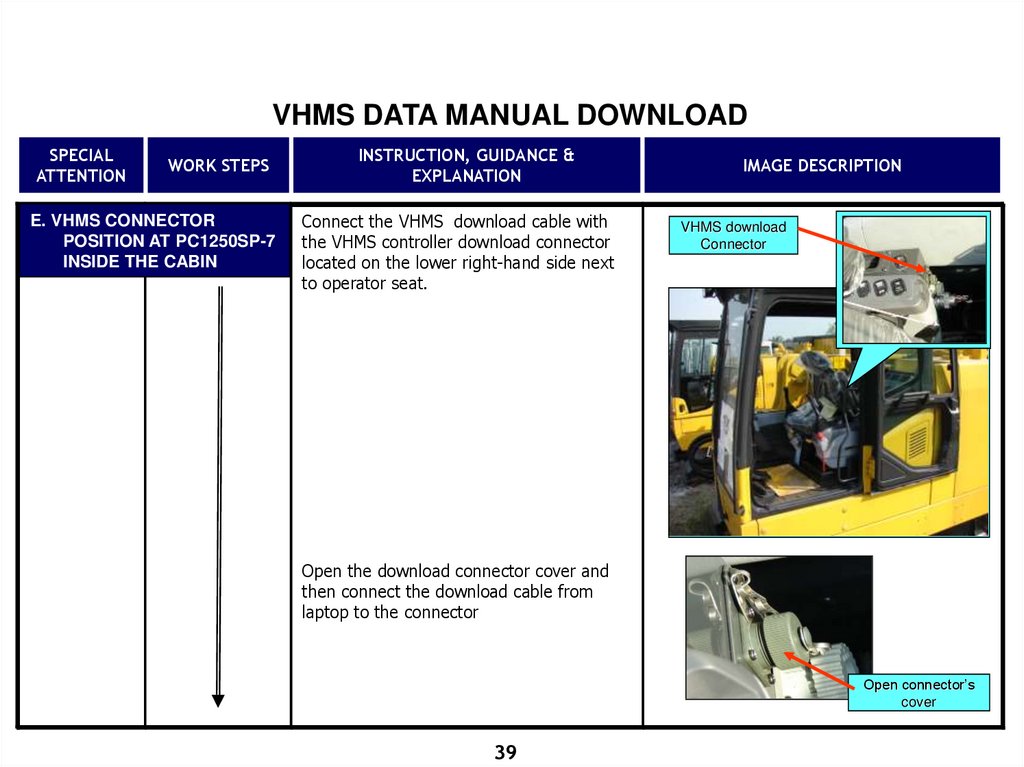
E. VHMS CONNECTOR
POSITION AT PC1250SP-7
INSIDE THE CABIN
INSTRUCTION, GUIDANCE &
EXPLANATION
Connect the VHMS download cable with
the VHMS controller download connector
located on the lower right-hand side next
to operator seat.
IMAGE DESCRIPTION
VHMS download
Connector
Open the download connector cover and
then connect the download cable from
laptop to the connector
Open connector’s
cover
39
40.
VHMS DATA MANUAL DOWNLOADSPECIAL
ATTENTION
WORK STEPS
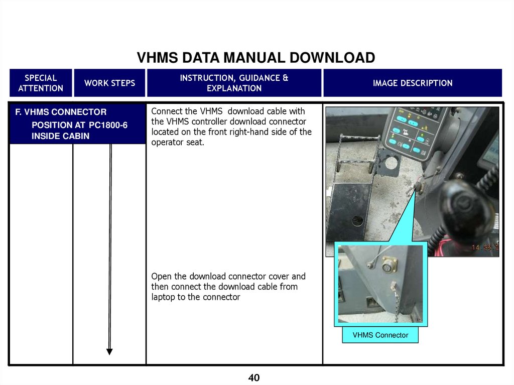
F. VHMS CONNECTOR
POSITION AT PC1800-6
INSIDE CABIN
INSTRUCTION, GUIDANCE &
EXPLANATION
IMAGE DESCRIPTION
Connect the VHMS download cable with
the VHMS controller download connector
located on the front right-hand side of the
operator seat.
Open the download connector cover and
then connect the download cable from
laptop to the connector
VHMS Connector
40
41.
VHMS DATA MANUAL DOWNLOADSPECIAL
ATTENTION
WORK STEPS
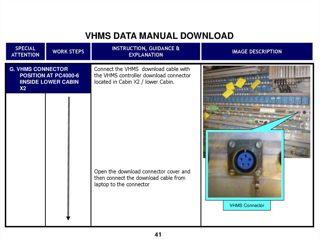
G. VHMS CONNECTOR
POSITION AT PC4000-6
IINSIDE LOWER CABIN
X2
INSTRUCTION, GUIDANCE &
EXPLANATION
IMAGE DESCRIPTION
Connect the VHMS download cable with
the VHMS controller download connector
located in Cabin X2 / lower Cabin.
Open the download connector cover and
then connect the download cable from
laptop to the connector
VHMS Connector
41
42.
VHMS DATA MANUAL DOWNLOADSPECIAL
ATTENTION
WORK STEPS
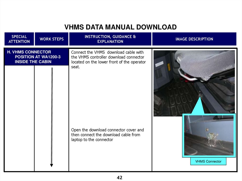
H. VHMS CONNECTOR
POSITION AT WA1200-3
INSIDE THE CABIN
INSTRUCTION, GUIDANCE &
EXPLANATION
IMAGE DESCRIPTION
Connect the VHMS download cable with
the VHMS controller download connector
located on the lower front of the operator
seat.
Open the download connector cover and
then connect the download cable from
laptop to the connector
VHMS Connector
42
43.
VHMS DATA MANUAL DOWNLOADSPECIAL
ATTENTION
Switch
Starting
Position: On
WORK STEPS
<1>
Start VHMS
Download
INSTRUCTION, GUIDANCE &
EXPLANATION
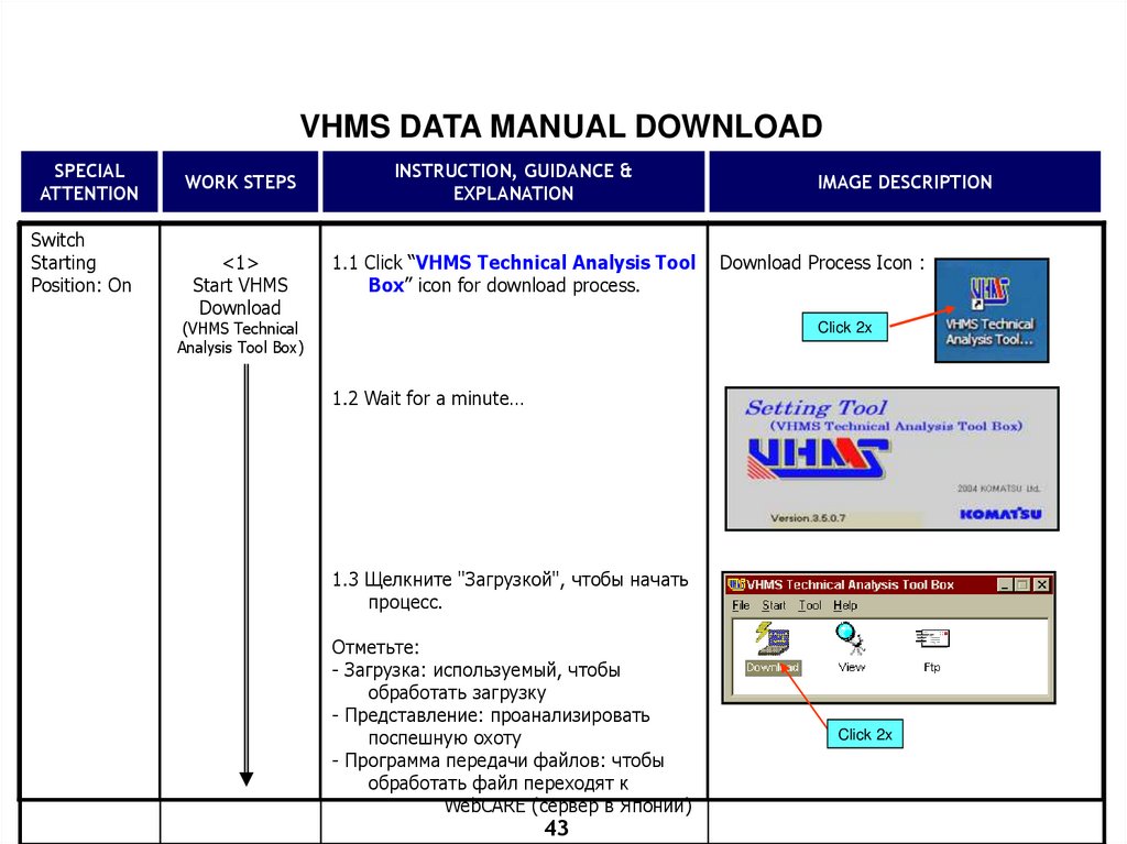
1.1 Click “VHMS Technical Analysis Tool
Box” icon for download process.
(VHMS Technical
Analysis Tool Box)
IMAGE DESCRIPTION
Download Process Icon :
Click 2x
1.2 Wait for a minute…
1.3 Щелкните "Загрузкой", чтобы начать
процесс.
Отметьте:
- Загрузка: используемый, чтобы
обработать загрузку
- Представление: проанализировать
поспешную охоту
- Программа передачи файлов: чтобы
обработать файл переходят к
WebCARE (сервер в Японии)
43
Click 2x
44.
VHMS DATA MANUAL DOWNLOADSPECIAL
ATTENTION
Switch
Starting
Position: On
WORK STEPS
<2>
Starting
Download
Process
INSTRUCTION, GUIDANCE &
EXPLANATION
IMAGE DESCRIPTION
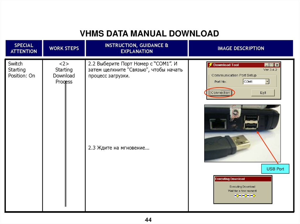
2.2 Выберите Порт Номер с “COM1”. И
затем щелкните "Связью", чтобы начать
процесс загрузки.
2.3 Ждите на мгновение...
USB Port
44
45.
VHMS DATA MANUAL DOWNLOADSPECIAL
ATTENTION
WORK STEPS
INSTRUCTION, GUIDANCE &
EXPLANATION
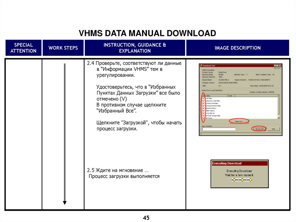
2.4 Проверьте, соответствуют ли данные
в “Информации VHMS” тем в
урегулировании.
Удостоверьтесь, что в “Избранных
Пунктах Данных Загрузки” все было
отмечено (V)
В противном случае щелкните
“Избранный Все”.
Щелкните "Загрузкой", чтобы начать
процесс загрузки.
2.5 Ждите на мгновение …
Процесс загрузки выполняется
45
IMAGE DESCRIPTION
46.
VHMS DATA MANUAL DOWNLOADSPECIAL
ATTENTION
Switch
Starting
Position: On
WORK STEPS
INSTRUCTION, GUIDANCE &
EXPLANATION
<3>
Download
Process
Completed
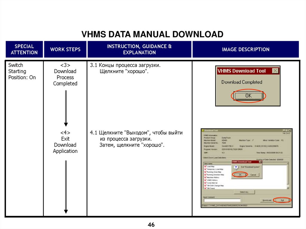
3.1 Концы процесса загрузки.
Щелкните "хорошо".
<4>
Exit
Download
Application
4.1 Щелкните "Выходом", чтобы выйти
из процесса загрузки.
Затем, щелкните "хорошо".
46
IMAGE DESCRIPTION
47.
VHMS DATA MANUAL DOWNLOADSPECIAL
ATTENTION
Switch
Starting
Position: Off
WORK STEPS
<5>
Checking
Download
Result
INSTRUCTION, GUIDANCE &
EXPLANATION
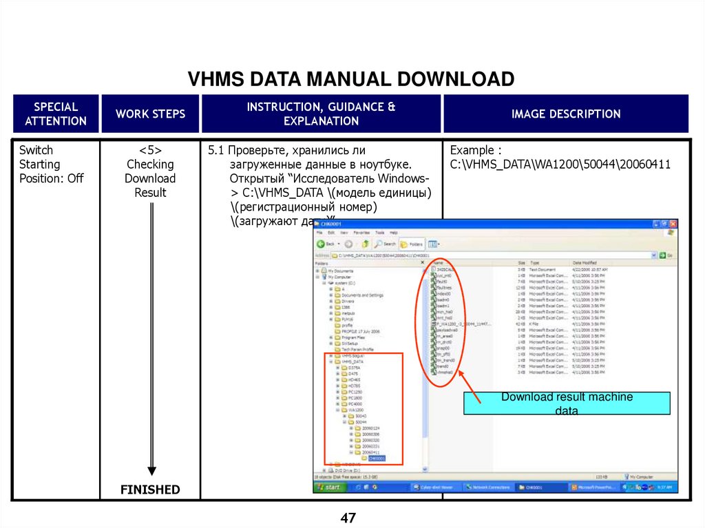
5.1 Проверьте, хранились ли
загруженные данные в ноутбуке.
Открытый “Исследователь Windows> C:\VHMS_DATA \(модель единицы)
\(регистрационный номер)
\(загружают дату)”.
IMAGE DESCRIPTION
Example :
C:\VHMS_DATA\WA1200\50044\20060411
Download result machine
data
FINISHED
47
48.
WIRELESS DOWNLOAD VHMS DATA48
49.
ЗАГРУЗКА РАДИО ДАННЫХ VHMSЗагрузка Радио ДАННЫХ VHMS - процесс загрузки ДАННЫХ VHMS от
Беспроводной Единицы, используя Беспроводное Средство Сети,
доступное в книге Примечания PC с максимальным диапазоном 150
метров и который не должен быть затруднен Металлами и или Холмы.
Чтобы позволить Беспроводную Загрузку ДАННЫХ VHMS, каждая
Единица со связанным упоминает ниже, будет во-первых
оборудованный беспроводным инструментом (модем).
Единицами Komatsu’s, которые были развиты и оборудованы
Беспроводным Типом Диспетчер VHMS, является HD465-7, HD785/9855, HD785-7, PC1250SP-7 & D375A-5 в машинах со
специфическим/самым новым Регистрационным номером.
49
50.
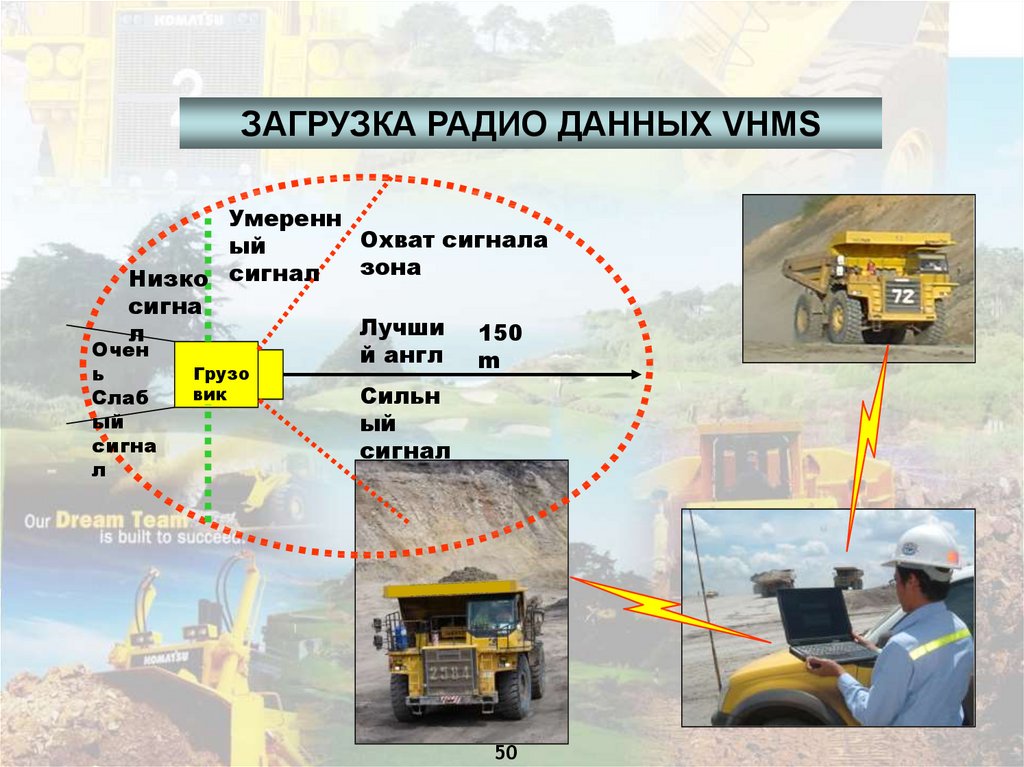
ЗАГРУЗКА РАДИО ДАННЫХ VHMSУмеренн
Охват сигнала
ый
зона
Низко сигнал
сигна
Лучши 150
л
Очен
й англ
m
Грузо
ь
Слаб
ый
сигна
л
вик
Сильн
ый
сигнал
50
51.
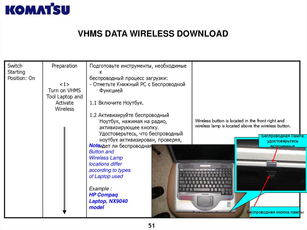
VHMS DATA WIRELESS DOWNLOADSwitch
Starting
Position: On
Preparation
<1>
Turn on VHMS
Tool Laptop and
Activate
Wireless
Подготовьте инструменты, необходимые
к
беспроводный процесс загрузки:
- Отметьте Книжный PC с Беспроводной
Функцией
1.1 Включите Ноутбук.
1.2 Активизируйте беспроводный
Ноутбук, нажимая на радио,
активизирующее кнопку.
Удостоверьтесь, что беспроводный
ноутбук активизирован, проверяя,
Noteидет
:
ли беспроводная лампа или нет.
Button and
Wireless Lamp
locations differ
according to types
of Laptop used
Example :
HP Compaq
Laptop, NX9040
model
Wireless button is located in the front right and
wireless lamp is located above the wireless button.
Беспроводная Лампа,
удостоверьтесь
включенные
Беспроводная кнопка лампы
51
52.
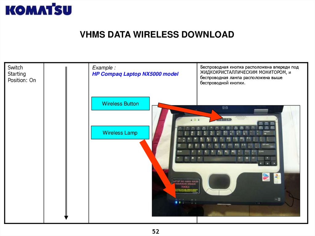
VHMS DATA WIRELESS DOWNLOADSwitch
Starting
Position: On
Example :
HP Compaq Laptop NX5000 model
Wireless Button
Wireless Lamp
52
Беспроводная кнопка расположена впереди под
ЖИДКОКРИСТАЛЛИЧЕСКИМ МОНИТОРОМ, и
беспроводная лампа расположена выше
беспроводной кнопки.
53.
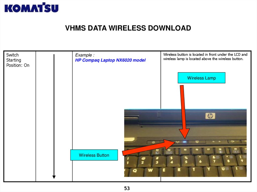
VHMS DATA WIRELESS DOWNLOADSwitch
Starting
Position: On
Example :
HP Compaq Laptop NX6020 model
Wireless button is located in front under the LCD and
wireless lamp is located above the wireless button.
Wireless Lamp
Wireless Button
53
54.
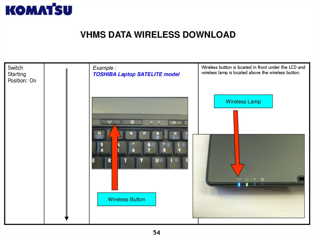
VHMS DATA WIRELESS DOWNLOADSwitch
Starting
Position: On
Example :
TOSHIBA Laptop SATELITE model
Wireless button is located in front under the LCD and
wireless lamp is located above the wireless button.
Wireless Lamp
Wireless Button
54
55.
VHMS DATA WIRELESS DOWNLOADSwitch
Starting
Position: On
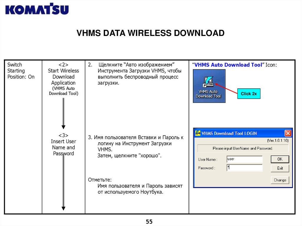
<2>
Start Wireless
Download
Application
2.
Щелкните “Авто изображением”
Инструмента Загрузки VHMS, чтобы
выполнить беспроводный процесс
загрузки.
(VHMS Auto
Download Tool)
<3>
Insert User
Name and
Password
“VHMS Auto Download Tool” Icon:
Click 2x
3. Имя пользователя Вставки и Пароль к
логину на Инструмент Загрузки
VHMS.
Затем, щелкните "хорошо".
Отметьте:
Имя пользователя и Пароль зависят
от используемого Ноутбука.
55
56.
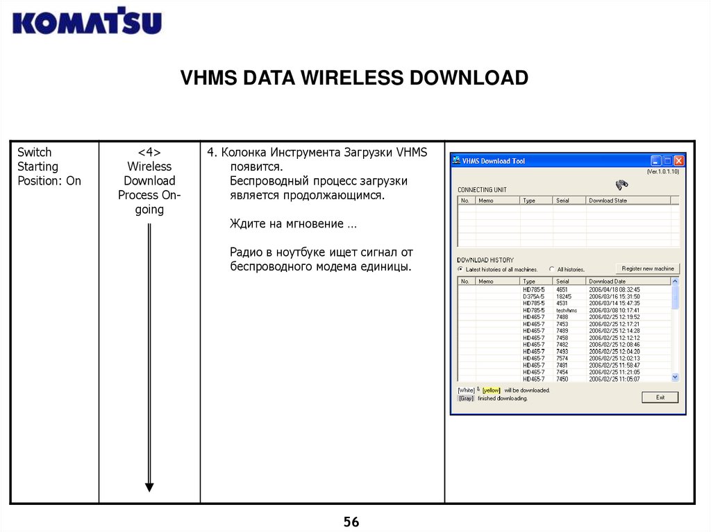
VHMS DATA WIRELESS DOWNLOADSwitch
Starting
Position: On
<4>
Wireless
Download
Process Ongoing
4. Колонка Инструмента Загрузки VHMS
появится.
Беспроводный процесс загрузки
является продолжающимся.
Ждите на мгновение …
Радио в ноутбуке ищет сигнал от
беспроводного модема единицы.
56
57.
VHMS DATA WIRELESS DOWNLOADSwitch
Starting
Position: On
<5>
Wireless
Download
Process
Completer
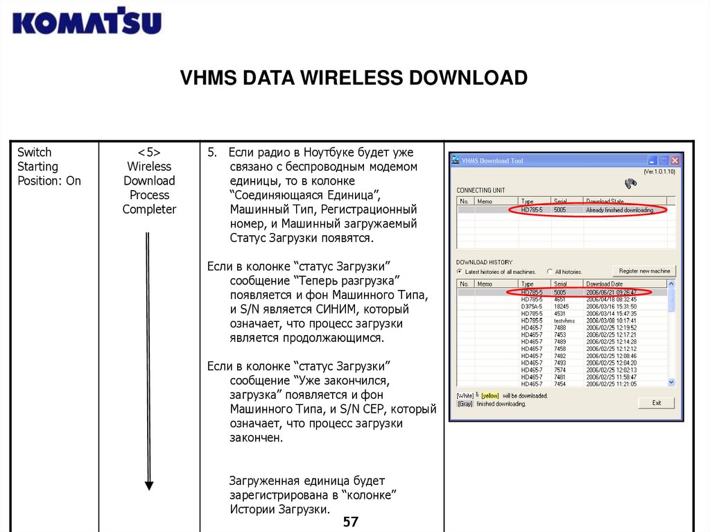
5. Если радио в Ноутбуке будет уже
связано с беспроводным модемом
единицы, то в колонке
“Соединяющаяся Единица”,
Машинный Тип, Регистрационный
номер, и Машинный загружаемый
Статус Загрузки появятся.
Если в колонке “статус Загрузки”
сообщение “Теперь разгрузка”
появляется и фон Машинного Типа,
и S/N является СИНИМ, который
означает, что процесс загрузки
является продолжающимся.
Если в колонке “статус Загрузки”
сообщение “Уже закончился,
загрузка” появляется и фон
Машинного Типа, и S/N СЕР, который
означает, что процесс загрузки
закончен.
Загруженная единица будет
зарегистрирована в “колонке”
Истории Загрузки.
57
58.
VHMS DATA WIRELESS DOWNLOADSwitch
Starting
Position: On
<6>
Exit Application
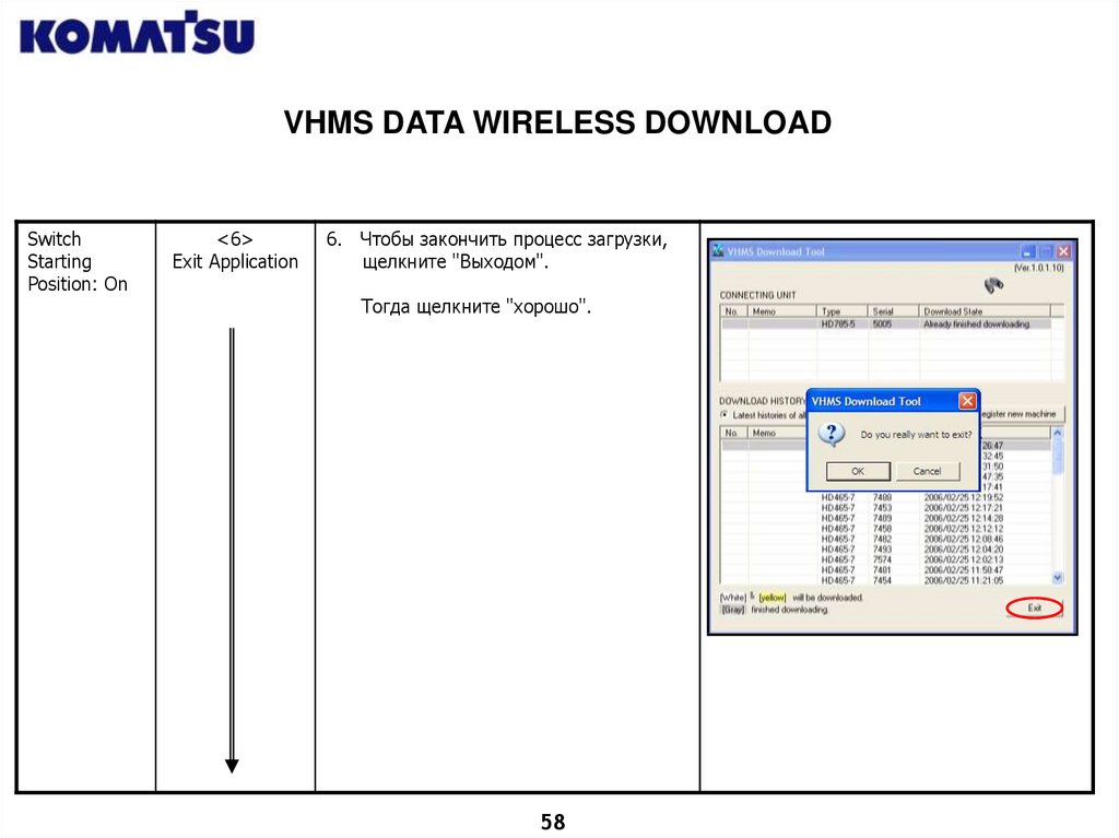
6. Чтобы закончить процесс загрузки,
щелкните "Выходом".
Тогда щелкните "хорошо".
58
59.
VHMS DATA WIRELESS DOWNLOAD<7>
Checking
Download
Result
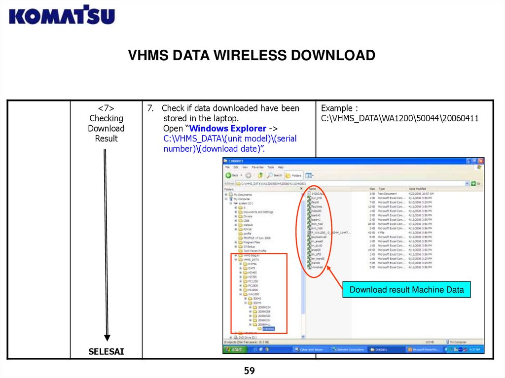
7. Check if data downloaded have been
stored in the laptop.
Open “Windows Explorer ->
C:\VHMS_DATA\(unit model)\(serial
number)\(download date)”.
Example :
C:\VHMS_DATA\WA1200\50044\20060411
Download result Machine Data
SELESAI
59
60.
VHMS DATA WIRELESS DOWNLOADTROUBLE SHOOTING
Switch
Starting
Position: On
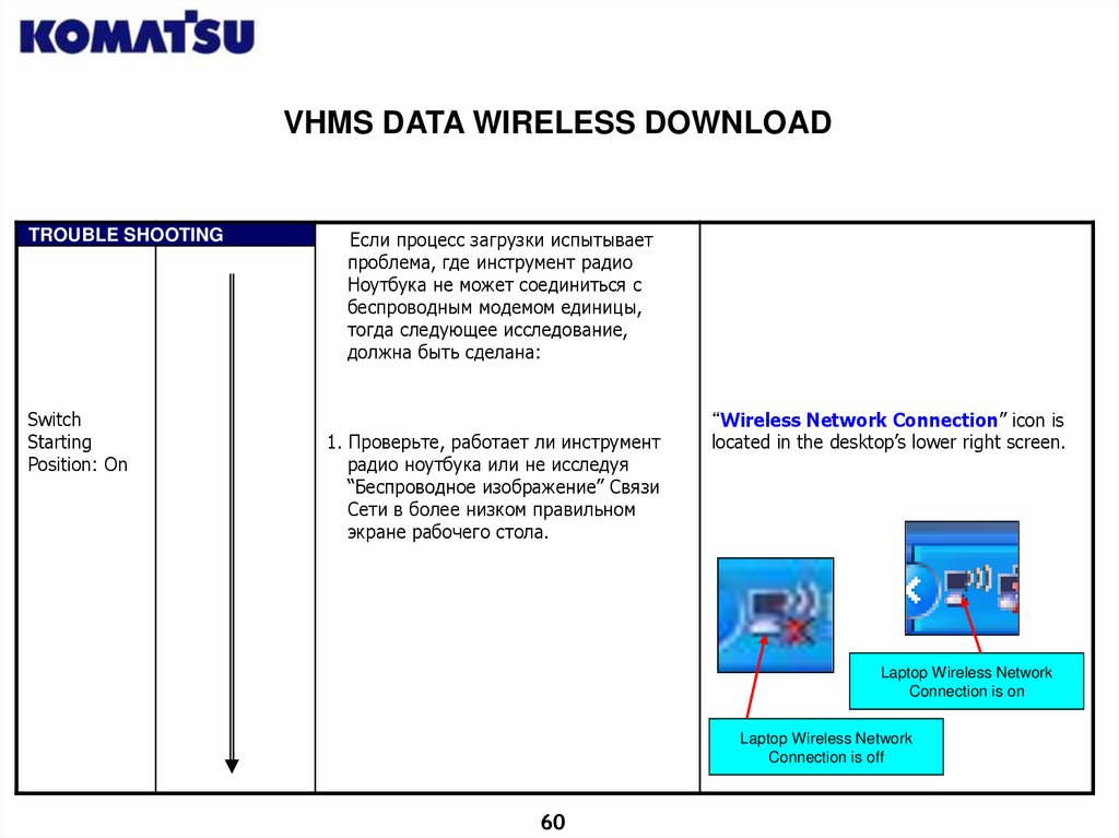
Если процесс загрузки испытывает
проблема, где инструмент радио
Ноутбука не может соединиться с
беспроводным модемом единицы,
тогда следующее исследование,
должна быть сделана:
1. Проверьте, работает ли инструмент
радио ноутбука или не исследуя
“Беспроводное изображение” Связи
Сети в более низком правильном
экране рабочего стола.
“Wireless Network Connection” icon is
located in the desktop’s lower right screen.
Laptop Wireless Network
Connection is on
Laptop Wireless Network
Connection is off
60
61.
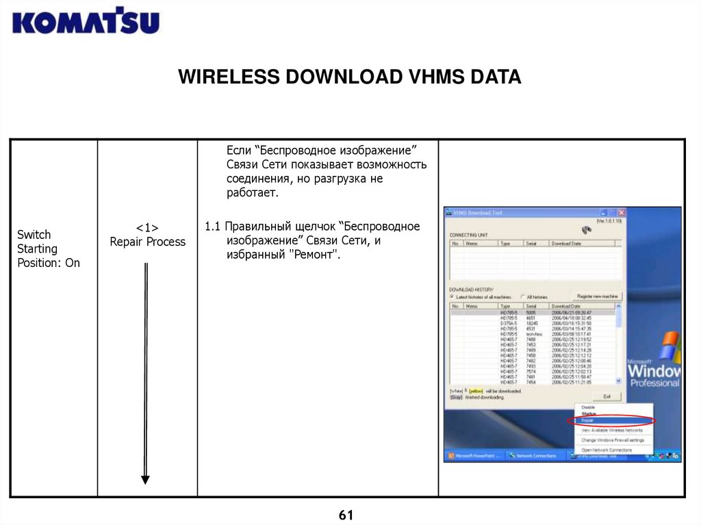
WIRELESS DOWNLOAD VHMS DATAЕсли “Беспроводное изображение”
Связи Сети показывает возможность
соединения, но разгрузка не
работает.
Switch
Starting
Position: On
<1>
Repair Process
1.1 Правильный щелчок “Беспроводное
изображение” Связи Сети, и
избранный "Ремонт".
61
62.
WIRELESS DOWNLOAD VHMS DATAStarting
Switch
Position: ON
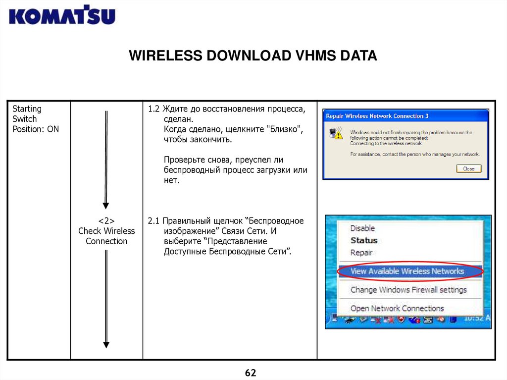
1.2 Ждите до восстановления процесса,
сделан.
Когда сделано, щелкните "Близко",
чтобы закончить.
Проверьте снова, преуспел ли
беспроводный процесс загрузки или
нет.
<2>
Check Wireless
Connection
2.1 Правильный щелчок “Беспроводное
изображение” Связи Сети. И
выберите “Представление
Доступные Беспроводные Сети”.
62
63.
WIRELESS DOWNLOAD VHMS DATAStarting
Switch
Position: ON
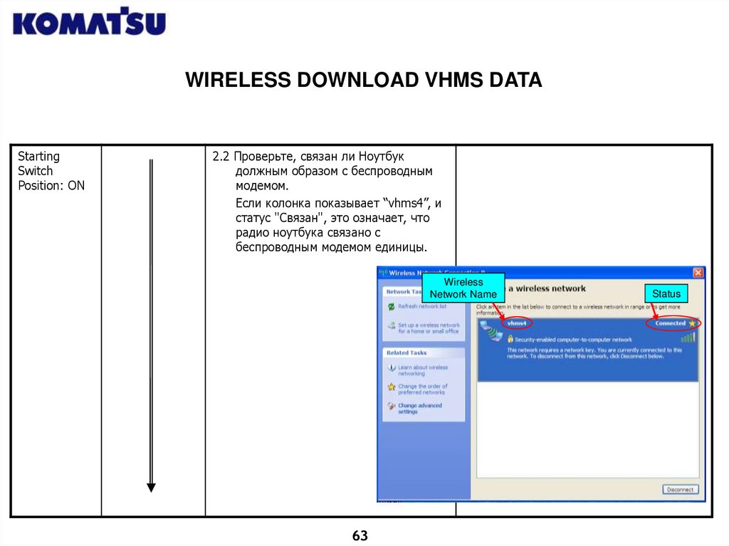
2.2 Проверьте, связан ли Ноутбук
должным образом с беспроводным
модемом.
Если колонка показывает “vhms4”, и
статус "Связан", это означает, что
радио ноутбука связано с
беспроводным модемом единицы.
Wireless
Network Name
63
Status
64.
WIRELESS DOWNLOAD VHMS DATAСтарт
Положения
Выключател
я: НА
<3>
Освежите
Беспроводную
Связь
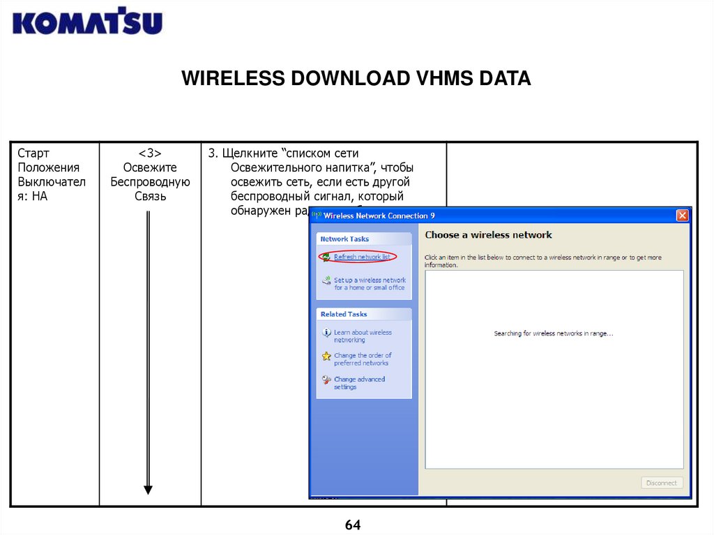
3. Щелкните “списком сети
Освежительного напитка”, чтобы
освежить сеть, если есть другой
беспроводный сигнал, который
обнаружен радио ноутбука.
64
65.
WIRELESS DOWNLOAD VHMS DATAStarting
Switch
Position: ON
<4>
Check Modem
Wireless
Condition
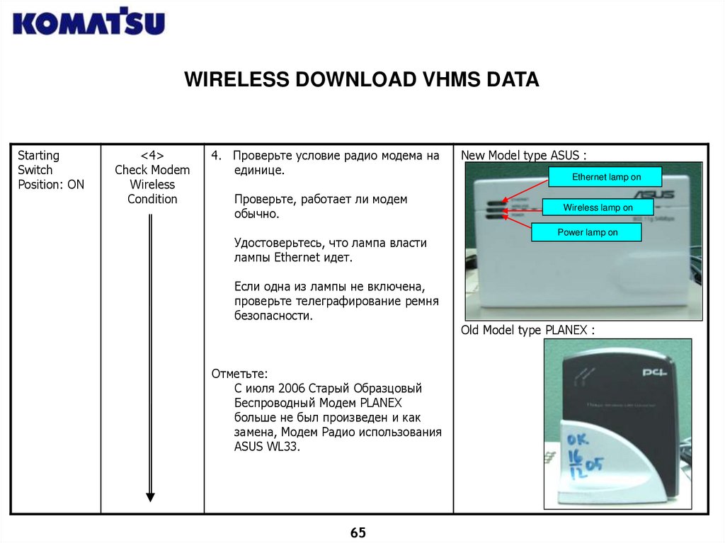
4. Проверьте условие радио модема на
единице.
Проверьте, работает ли модем
обычно.
Удостоверьтесь, что лампа власти
лампы Ethernet идет.
Если одна из лампы не включена,
проверьте телеграфирование ремня
безопасности.
Отметьте:
С июля 2006 Старый Образцовый
Беспроводный Модем PLANEX
больше не был произведен и как
замена, Модем Радио использования
ASUS WL33.
65
New Model type ASUS :
Ethernet lamp on
Wireless lamp on
Power lamp on
Old Model type PLANEX :
66.
VHMS BAGUS SOFTWARE66
67.
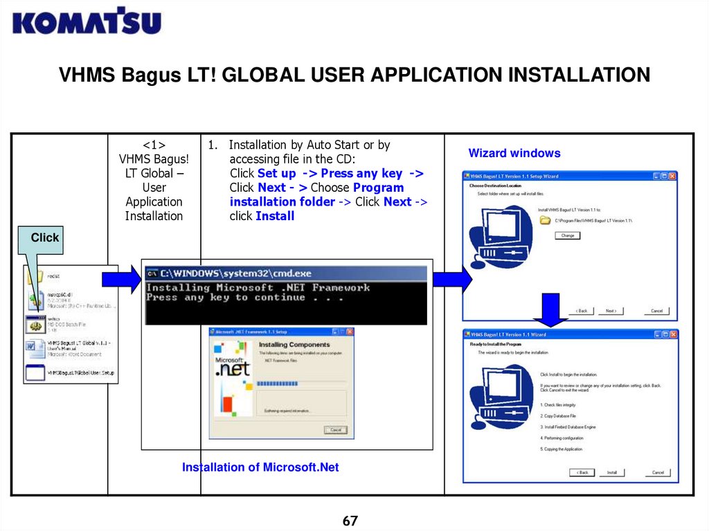
VHMS Bagus LT! GLOBAL USER APPLICATION INSTALLATION<1>
VHMS Bagus!
LT Global –
User
Application
Installation
1. Installation by Auto Start or by
accessing file in the CD:
Click Set up -> Press any key ->
Click Next - > Choose Program
installation folder -> Click Next ->
click Install
Click
Installation of Microsoft.Net
67
Wizard windows
68.
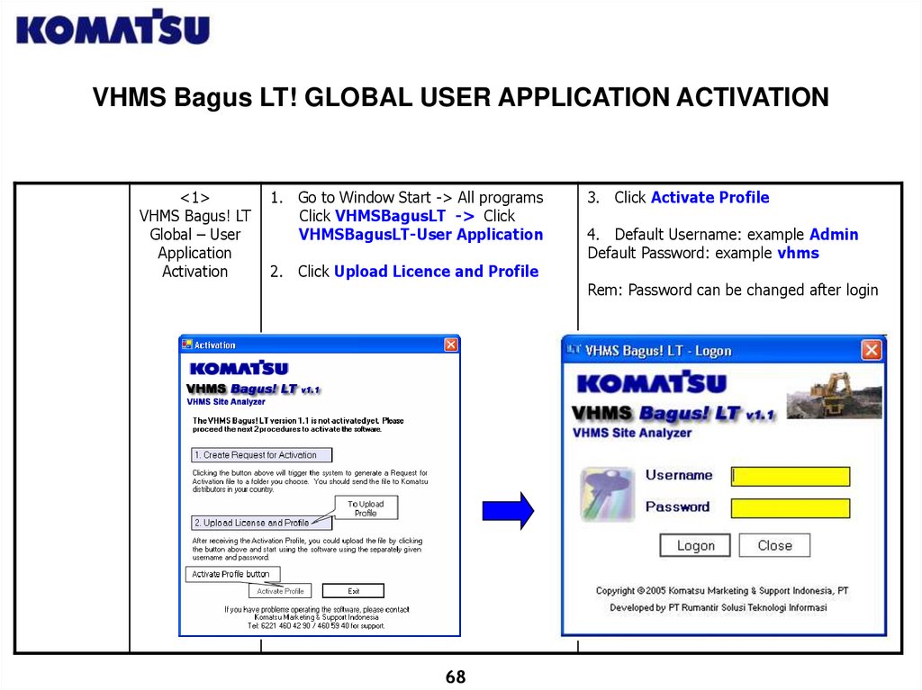
VHMS Bagus LT! GLOBAL USER APPLICATION ACTIVATION<1>
VHMS Bagus! LT
Global – User
Application
Activation
1. Go to Window Start -> All programs
Click VHMSBagusLT -> Click
VHMSBagusLT-User Application
2. Click Upload Licence and Profile
68
3. Click Activate Profile
4. Default Username: example Admin
Default Password: example vhms
Rem: Password can be changed after login
69.
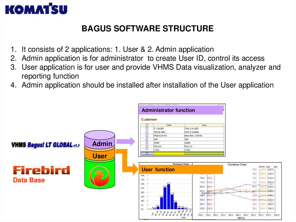
BAGUS SOFTWARE STRUCTURE1. It consists of 2 applications: 1. User & 2. Admin application
2. Admin application is for administrator to create User ID, control its access
3. User application is for user and provide VHMS Data visualization, analyzer and
reporting function
4. Admin application should be installed after installation of the User application
Administrator function
Admin
User
User function
Data Base
69
70.
VHMS BAGUS LT! GLOBAL USER APPLICATIONADDING NEW CUSTOMER
<1>
VHMS Bagus! LT
Global – User
Application
1. Go to Configuration :
Click Customer List
2. Click Edit -> Create double click
Code (yellow) & enter Customer
Code (Max 10 character) -> double
click Name and enter Customer
name (max 40 character)
Click Edit
3. Click Create and redo no 2
to enter new job site
4. Click Save
Click Create
Input Customer
70
71.
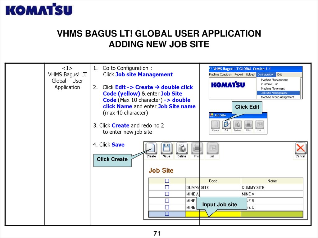
VHMS BAGUS LT! GLOBAL USER APPLICATIONADDING NEW JOB SITE
<1>
VHMS Bagus! LT
Global – User
Application
1. Go to Configuration :
Click Job site Management
2. Click Edit -> Create double click
Code (yellow) & enter Job Site
Code (Max 10 character) -> double
click Name and enter Job Site name
(max 40 character)
Click Edit
3. Click Create and redo no 2
to enter new job site
4. Click Save
Click Create
Input Job site
71
72.
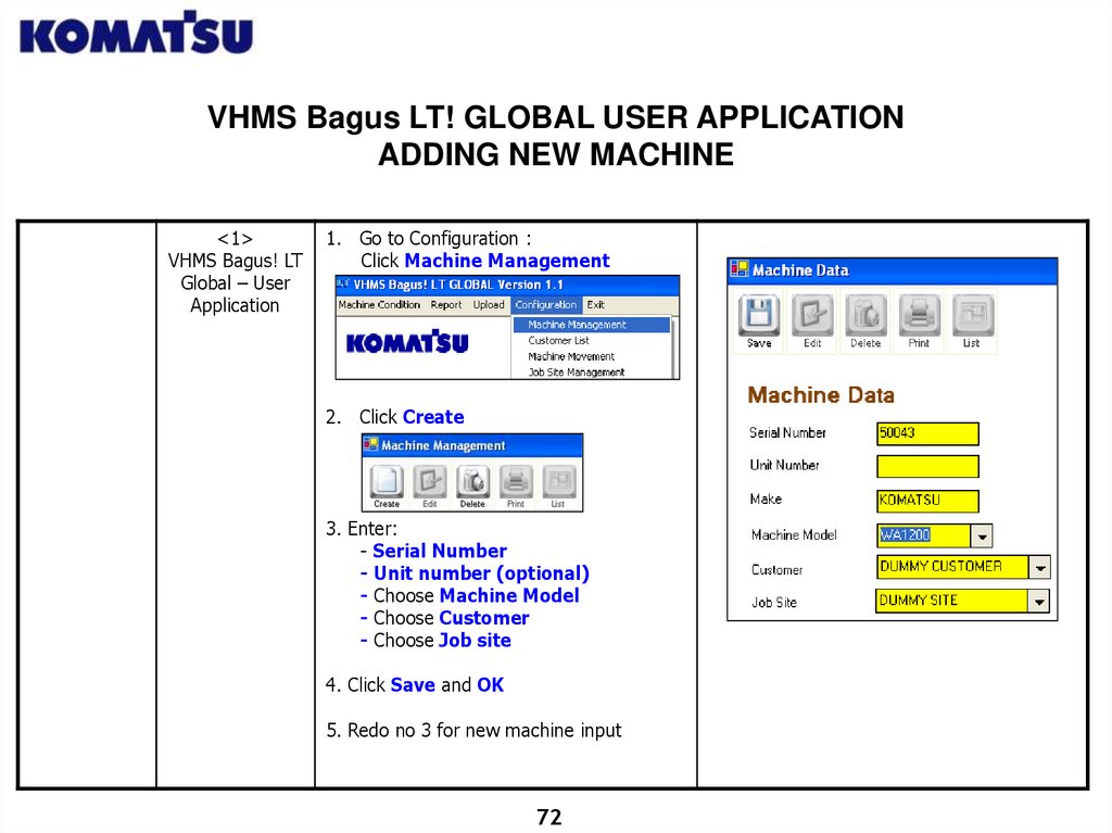
VHMS Bagus LT! GLOBAL USER APPLICATIONADDING NEW MACHINE
<1>
VHMS Bagus! LT
Global – User
Application
1. Go to Configuration :
Click Machine Management
2. Click Create
3. Enter:
- Serial Number
- Unit number (optional)
- Choose Machine Model
- Choose Customer
- Choose Job site
4. Click Save and OK
5. Redo no 3 for new machine input
72
73.
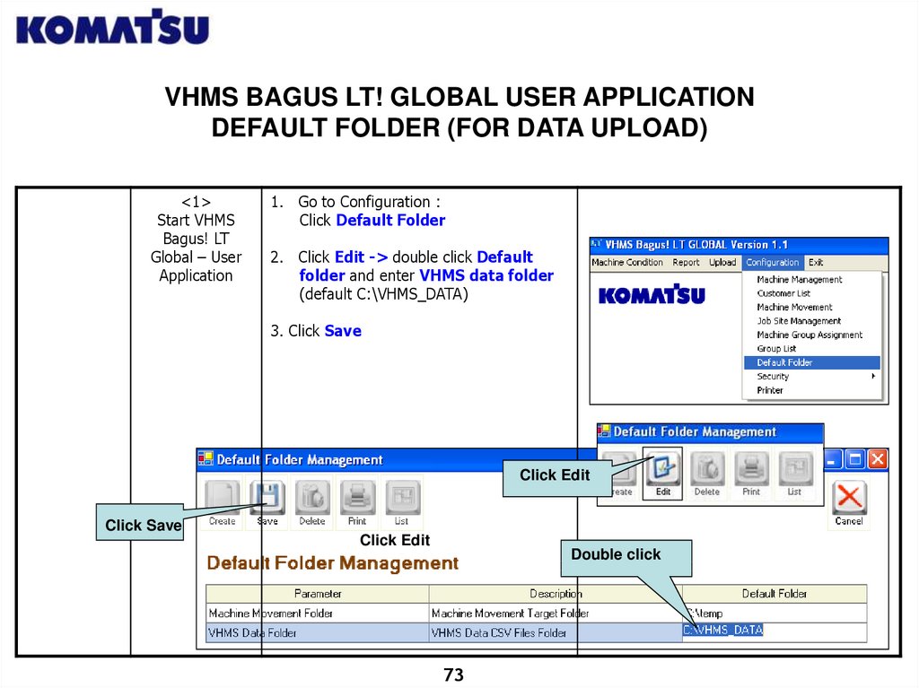
VHMS BAGUS LT! GLOBAL USER APPLICATIONDEFAULT FOLDER (FOR DATA UPLOAD)
<1>
Start VHMS
Bagus! LT
Global – User
Application
1. Go to Configuration :
Click Default Folder
2. Click Edit -> double click Default
folder and enter VHMS data folder
(default C:\VHMS_DATA)
3. Click Save
ClickEdit
Edit
Click
Click Save
Click Edit
Double click
73
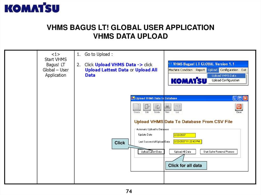
74.
VHMS BAGUS LT! GLOBAL USER APPLICATIONVHMS DATA UPLOAD
<1>
Start VHMS
Bagus! LT
Global – User
Application
1. Go to Upload :
2. Click Upload VHMS Data -> click
Upload Lattest Data or Upload All
Data
Click
Click for all data
74
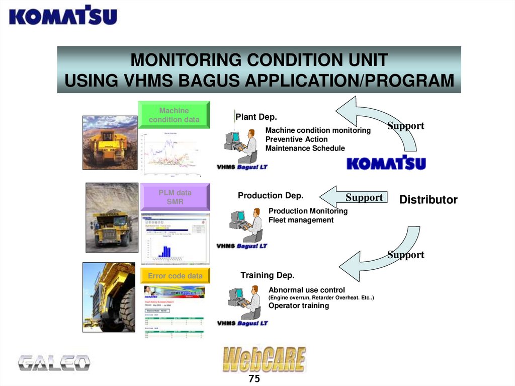
75.
MONITORING CONDITION UNITUSING VHMS BAGUS APPLICATION/PROGRAM
Machine
condition data
Plant Dep.
Machine condition monitoring
Preventive Action
Maintenance Schedule
PLM data
SMR
Production Dep.
Support
Support
Distributor
Production Monitoring
Fleet management
Support
Error code data
Training Dep.
Abnormal use control
(Engine overrun, Retarder Overheat. Etc..)
Operator training
75
76.
MONITORING CONDITION UNITUSING VHMS BAGUS APPLICATION
Definition:
VHMS Bagus is an application or software name which functions as a
supporting tool in changing the original download VHMS Data (CSV File) of the
unit to an easier-to-read display data (XML File).
Objective:
To make unit condition analysis quickly and accurately become easier after
downloading.
Advantages of VHMS Bagus among others:
1. Can display Trend Analysis from various parameter and choices according to
the unit / component's working hours suitable with user’s need in planning
maintenance preventive activities.
2. Can display Fault History originating from the unit / component according to
incident time and frequency to minimize and analyze the unit’s damage caused
by human error factor.
3. Can display Summary Payload Meter (for dump truck) which is integrated with
PLM II according to the time and number, so that data of whether a unit is
operating in an under-load or overload condition within one period can be
quickly attained.
76
77.
MONITORING CONDITION UNITUSING VHMS BAGUS APPLICATION
4. Can display data from unit including Customer name, Location, SMR, Warning
Message, Machine Status, etc.
5. Generally VHMS Bagus role can reduce the implementation frequency of PMClinic or PPM Manual so that it can reduce the unit’s Down Time and the
mechanic’s extra effort.
VHMS Bagus Application limitations:
- Mechanical component damage without sensor cannot be detected by VHMS
Bagus.
- VHMS Bagus display data accuracy is influenced by the consistency of
Periodical Maintenance of the unit’s VHMS System.
- Payload Meter Summary data is influenced by PLM II memory condition.
77
78.
MONITORING UNIT CONDITION USING VHMS BAGUS APPLICATION<1>
Start VHMS
Bagus LT – User
Application
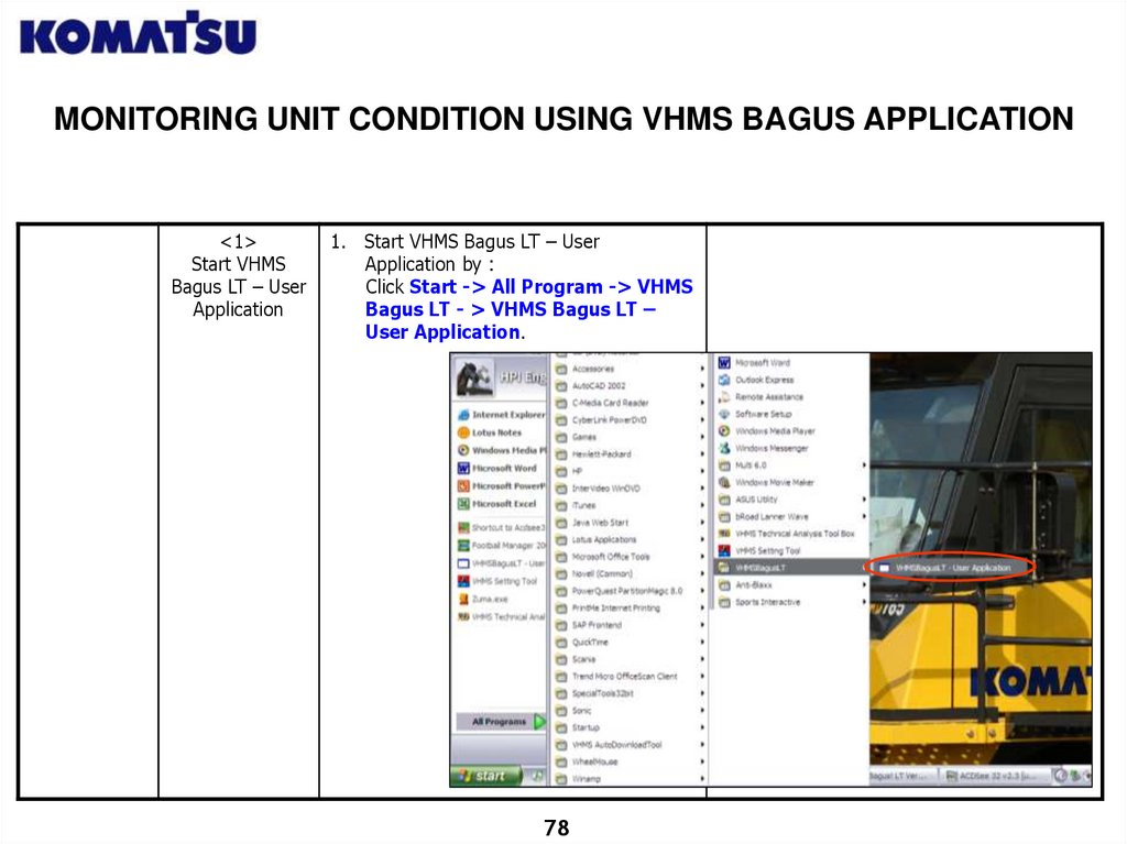
1. Start VHMS Bagus LT – User
Application by :
Click Start -> All Program -> VHMS
Bagus LT - > VHMS Bagus LT –
User Application.
78
79.
MONITORING UNIT CONDITION USING VHMS BAGUS APPLICATION<2>
Insert
Username and
Password
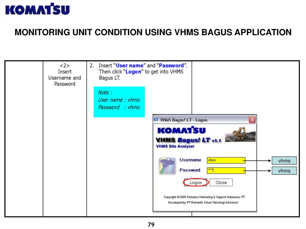
2. Insert “User name” and “Password”.
Then click “Logon” to get into VHMS
Bagus LT.
Note :
User name : vhms
Password : vhms
vhms
vhms
79
80.
MONITORING UNIT CONDITION USING VHMS BAGUS APPLICATION<3>
VHMS
Bagus LT – User
Application Main
Menu
Display
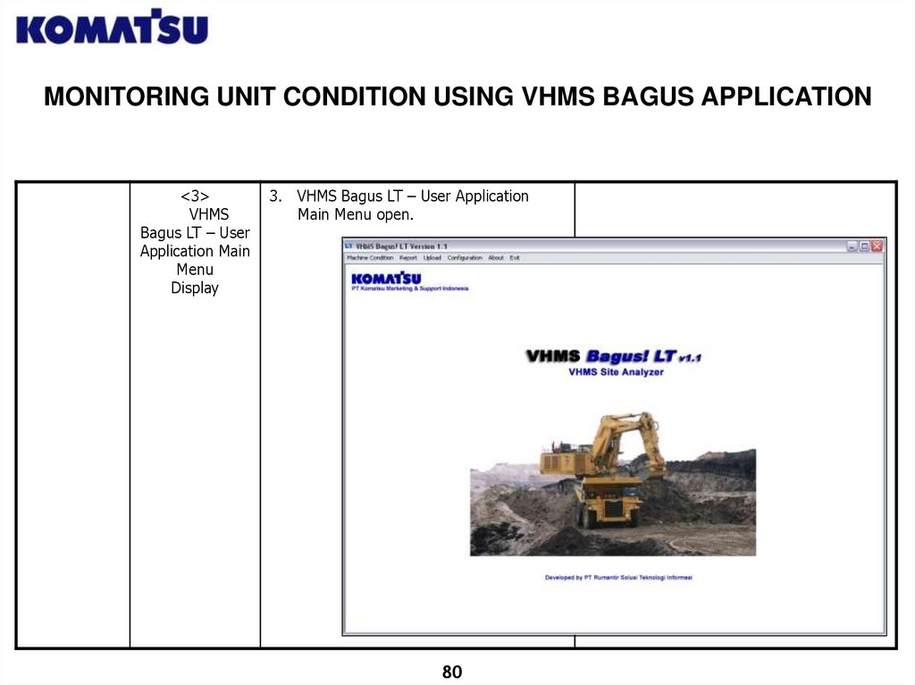
3. VHMS Bagus LT – User Application
Main Menu open.
80
81.
MONITORING UNIT CONDITION USING VHMS BAGUS APPLICATION<4>
Machine
Condition
Monitor
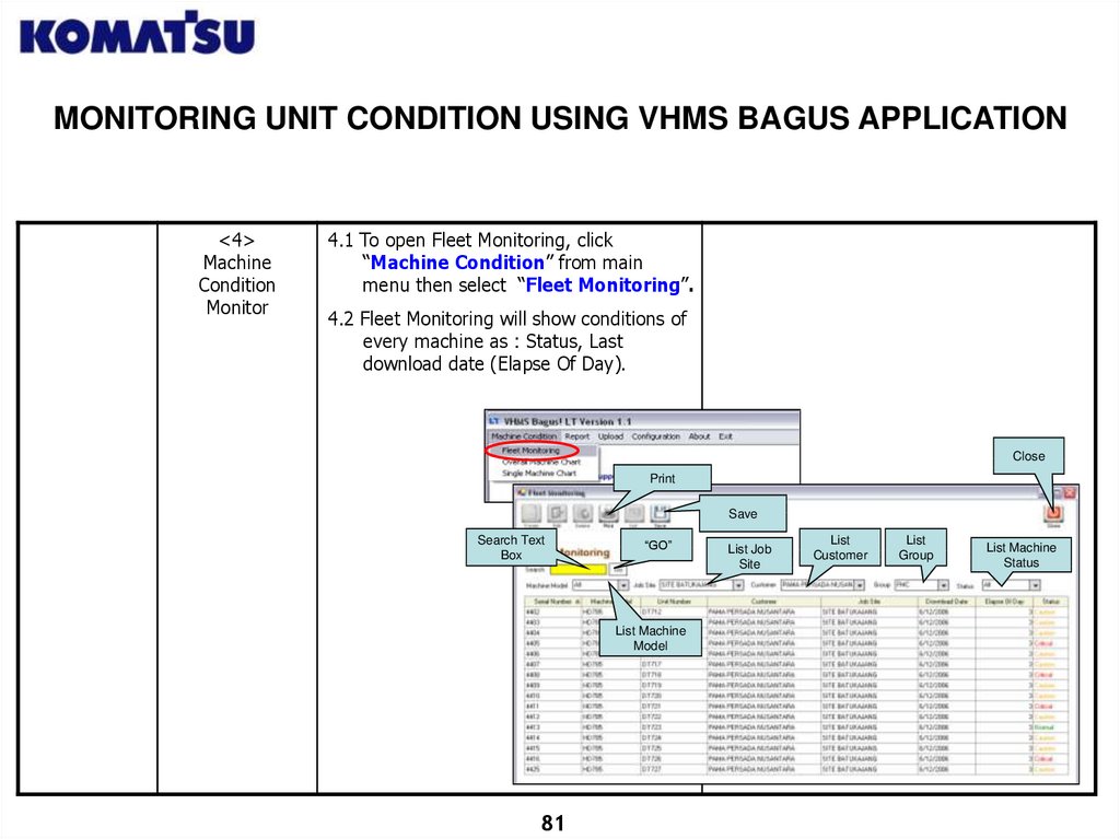
4.1 To open Fleet Monitoring, click
“Machine Condition” from main
menu then select “Fleet Monitoring”.
4.2 Fleet Monitoring will show conditions of
every machine as : Status, Last
download date (Elapse Of Day).
Close
Save
Search Text
Box
“GO”
List Machine
Model
81
List Job
Site
List
Customer
List
Group
List Machine
Status
82.
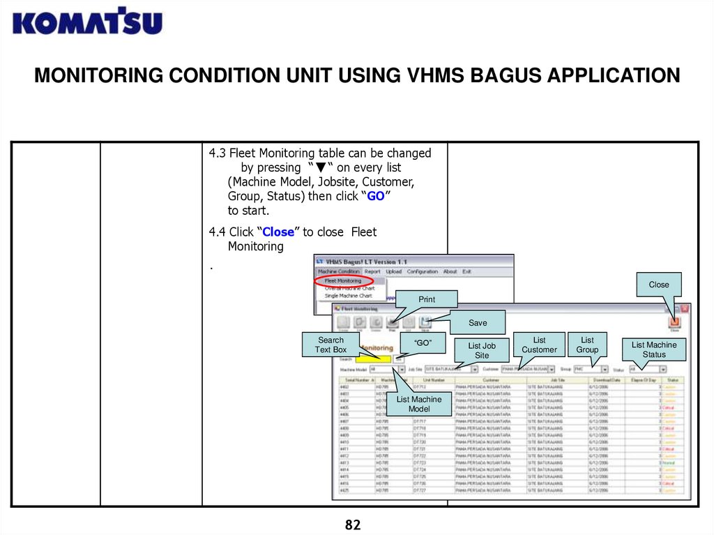
MONITORING CONDITION UNIT USING VHMS BAGUS APPLICATION4.3 Fleet Monitoring table can be changed
by pressing “ “ on every list
(Machine Model, Jobsite, Customer,
Group, Status) then click “GO”
to start.
4.4 Click “Close” to close Fleet
Monitoring
.
Close
Save
Search
Text Box
“GO”
List Machine
Model
82
List Job
Site
List
Customer
List
Group
List Machine
Status
83.
MONITORING UNIT CONDITION USING VHMS BAGUS APPLICATION<5>
Overall
Machine Chart
Monitor
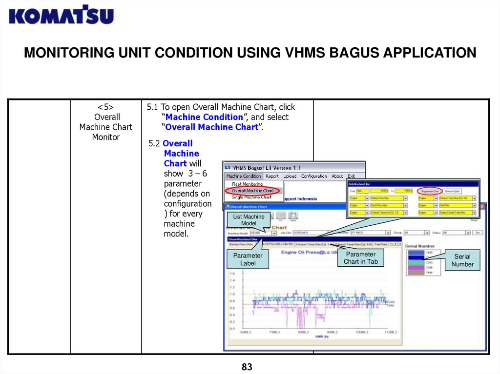
5.1 To open Overall Machine Chart, click
“Machine Condition”, and select
“Overall Machine Chart”.
5.2 Overall
Machine
Chart will
show 3 – 6
parameter
(depends on
configuration
) for every
machine
model.
List Machine
Model
Parameter
Label
83
Parameter
Chart in Tab
Serial
Number
84.
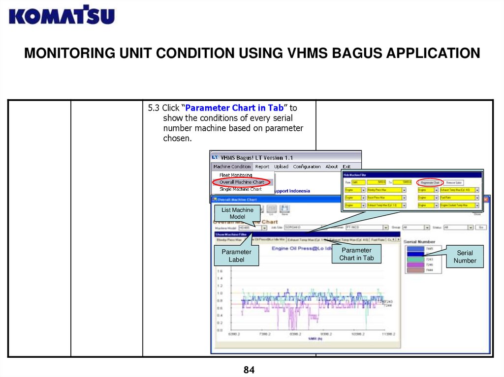
MONITORING UNIT CONDITION USING VHMS BAGUS APPLICATION5.3 Click “Parameter Chart in Tab” to
show the conditions of every serial
number machine based on parameter
chosen.
List Machine
Model
Parameter
Label
84
Parameter
Chart in Tab
Serial
Number
85.
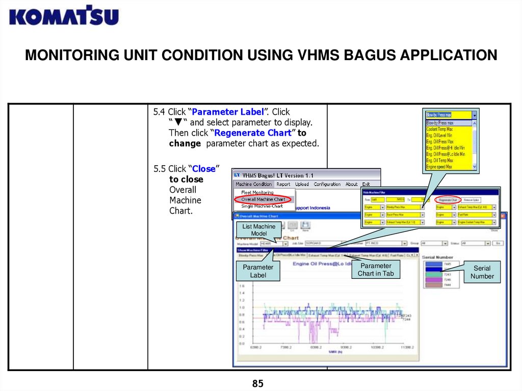
MONITORING UNIT CONDITION USING VHMS BAGUS APPLICATION5.4 Click “Parameter Label”. Click
“ “ and select parameter to display.
Then click “Regenerate Chart” to
change parameter chart as expected.
5.5 Click “Close”
to close
Overall
Machine
Chart.
List Machine
Model
Parameter
Label
85
Parameter
Chart in Tab
Serial
Number
86.
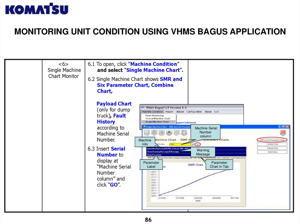
MONITORING UNIT CONDITION USING VHMS BAGUS APPLICATION<6>
Single Machine
Chart Monitor
6.1 To open, click “Machine Condition”
and select “Single Machine Chart”.
6.2 Single Machine Chart shows SMR and
Six Parameter Chart, Combine
Chart,
Payload Chart
(only for dump
truck), Fault
History
according to
Machine Serial
Number.
6.3 Insert Serial
Number to
display at
“Machine Serial
Number
column” and
click “GO”.
Machine Serial
Number
column
Machine
Info
Warning
Message
Parameter
Label
86
Parameter
Chart in Tab
87.
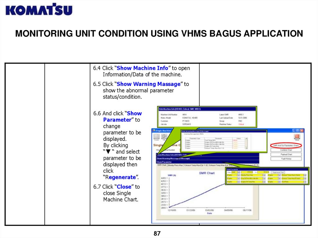
MONITORING UNIT CONDITION USING VHMS BAGUS APPLICATION6.4 Click “Show Machine Info” to open
Information/Data of the machine.
6.5 Click “Show Warning Massage” to
show the abnormal parameter
status/condition.
6.6 And click “Show
Parameter” to
change
parameter to be
displayed.
By clicking
“ “ and select
parameter to be
displayed then
click
“Regenerate”.
6.7 Click “Close” to
close Single
Machine Chart.
87
88.
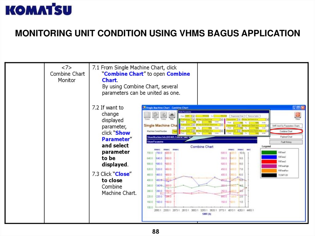
MONITORING UNIT CONDITION USING VHMS BAGUS APPLICATION<7>
Combine Chart
Monitor
7.1 From Single Machine Chart, click
“Combine Chart” to open Combine
Chart.
By using Combine Chart, several
parameters can be united as one.
7.2 If want to
change
displayed
parameter,
click “Show
Parameter”
and select
parameter
to be
displayed.
7.3 Click “Close”
to close
Combine
Machine Chart.
88
89.
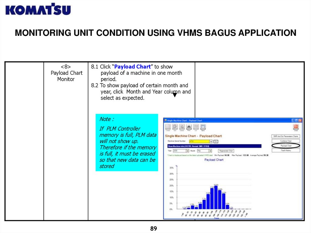
MONITORING UNIT CONDITION USING VHMS BAGUS APPLICATION<8>
Payload Chart
Monitor
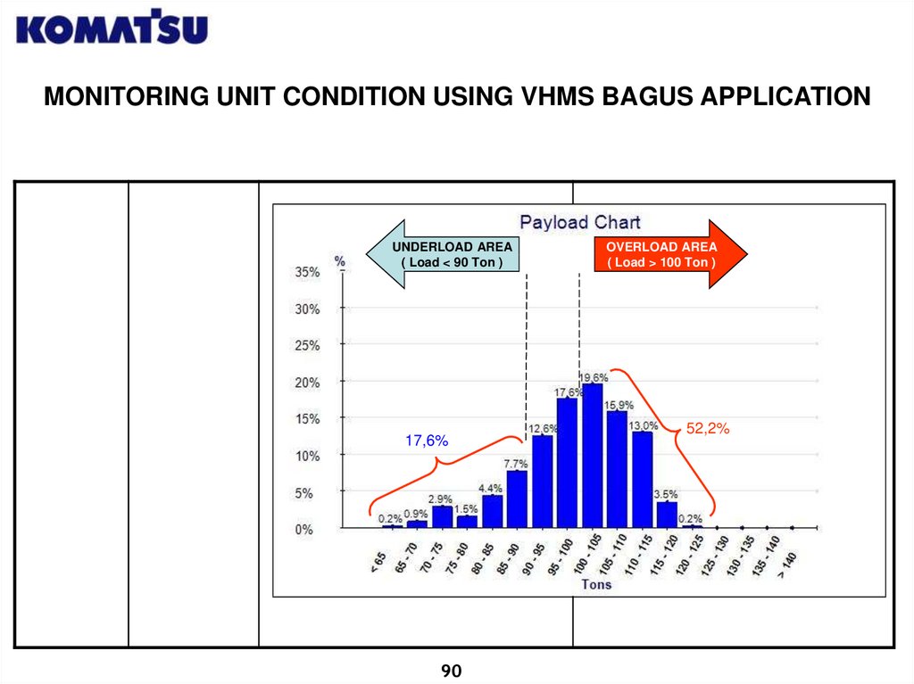
8.1 Click “Payload Chart” to show
payload of a machine in one month
period.
8.2 To show payload of certain month and
year, click Month and Year column and
select as expected.
Note :
If PLM Controller
memory is full, PLM data
will not show up.
Therefore if the memory
is full, it must be erased
so that new data can be
stored
89
90.
MONITORING UNIT CONDITION USING VHMS BAGUS APPLICATIONUNDERLOAD AREA
( Load < 90 Ton )
17,6%
90
OVERLOAD AREA
( Load > 100 Ton )
52,2%
91.
MONITORING UNIT CONDITION USING VHMS BAGUS APPLICATION<9>
Fault History
Monitor
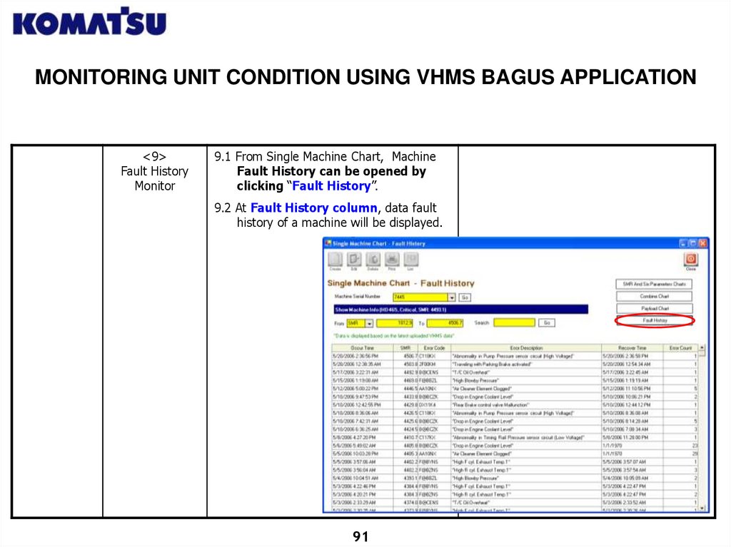
9.1 From Single Machine Chart, Machine
Fault History can be opened by
clicking “Fault History”.
9.2 At Fault History column, data fault
history of a machine will be displayed.
91
92.
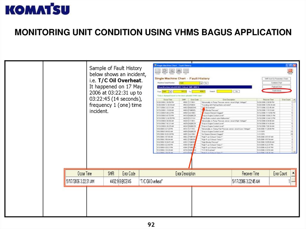
MONITORING UNIT CONDITION USING VHMS BAGUS APPLICATIONSample of Fault History
below shows an incident,
i.e. T/C Oil Overheat.
It happened on 17 May
2006 at 03:22:31 up to
03:22:45 (14 seconds),
frequency 1 (one) time
incident.
92
93.
MONITORING UNIT CONDITION USING VHMS BAGUS APPLICATION<10>
Eliminating
Spike
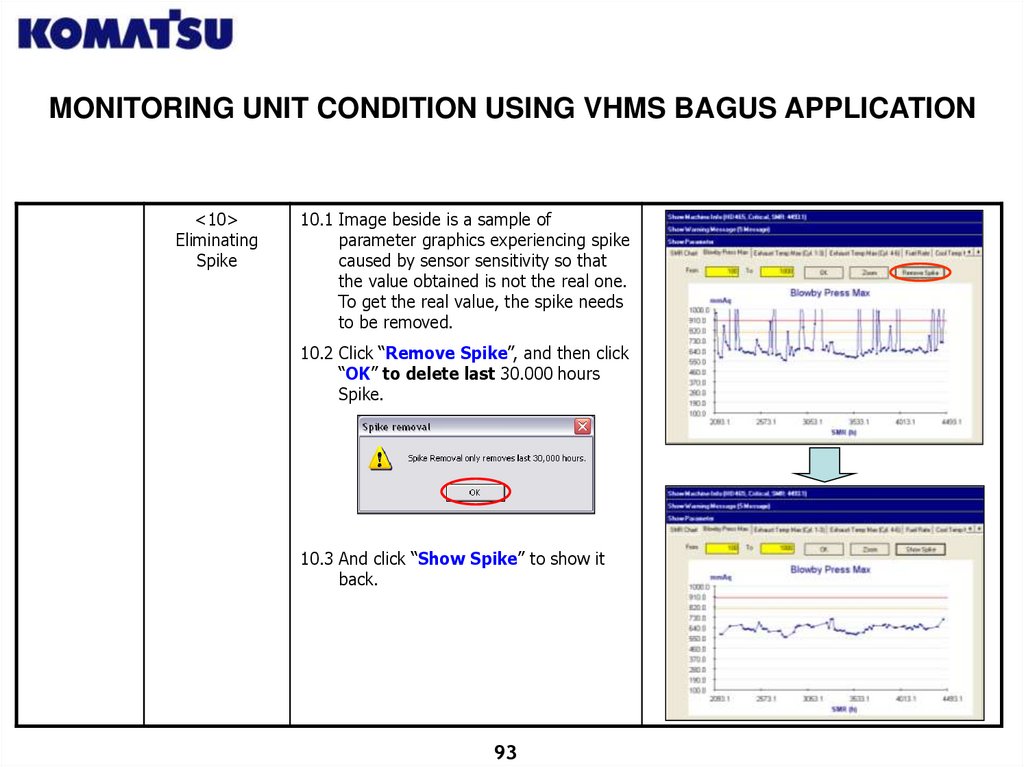
10.1 Image beside is a sample of
parameter graphics experiencing spike
caused by sensor sensitivity so that
the value obtained is not the real one.
To get the real value, the spike needs
to be removed.
10.2 Click “Remove Spike”, and then click
“OK” to delete last 30.000 hours
Spike.
10.3 And click “Show Spike” to show it
back.
93
94.
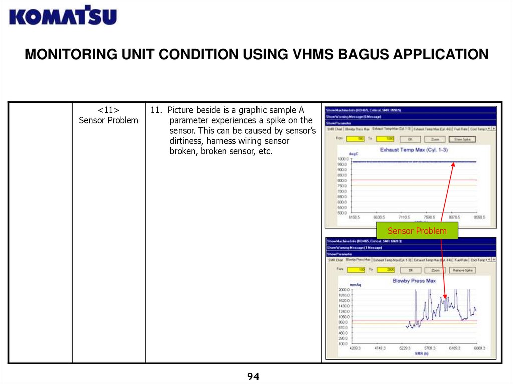
MONITORING UNIT CONDITION USING VHMS BAGUS APPLICATION<11>
Sensor Problem
11. Picture beside is a graphic sample A
parameter experiences a spike on the
sensor. This can be caused by sensor’s
dirtiness, harness wiring sensor
broken, broken sensor, etc.
Sensor Problem
94
95.
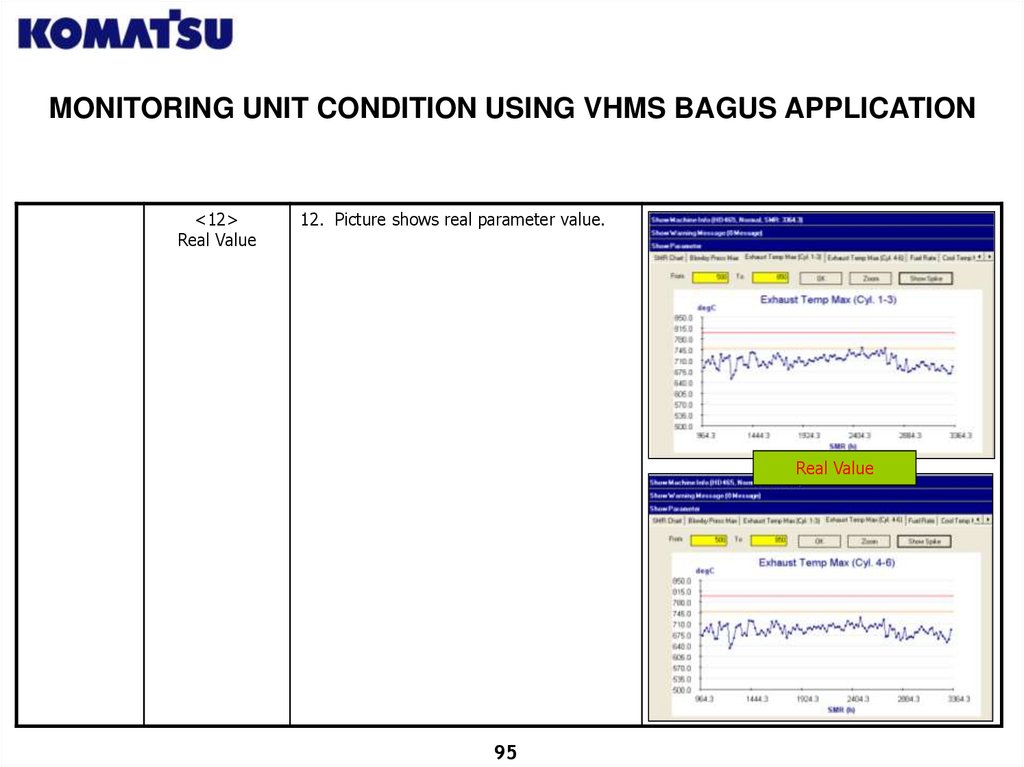
MONITORING UNIT CONDITION USING VHMS BAGUS APPLICATION<12>
Real Value
12. Picture shows real parameter value.
Real Value
95
96.
VHMS BAGUS LT! GLOBAL USER APPLICATIONCREATING REPORT
<1>
Start VHMS
Bagus! LT
Global – User
Application
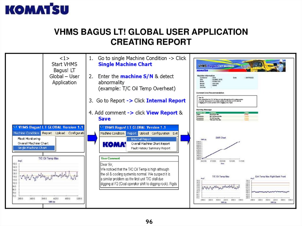
1. Go to single Machine Condition -> Click
Single Machine Chart
2. Enter the machine S/N & detect
abnormality
(example: T/C Oil Temp Overheat)
3. Go to Report -> Click Internal Report
4. Add comment -> click View Report &
Save
96
97.
VHMS BAGUS LT! GLOBAL USER APPLICATIONCREATING OVERALL MACHINE REPORT
<1>
Start VHMS
Bagus! LT
Global – User
Application
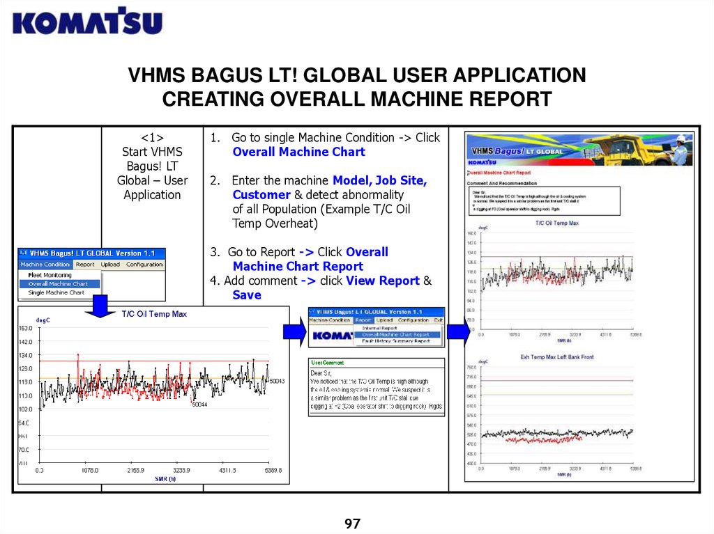
1. Go to single Machine Condition -> Click
Overall Machine Chart
2. Enter the machine Model, Job Site,
Customer & detect abnormality
of all Population (Example T/C Oil
Temp Overheat)
3. Go to Report -> Click Overall
Machine Chart Report
4. Add comment -> click View Report &
Save
97
98.
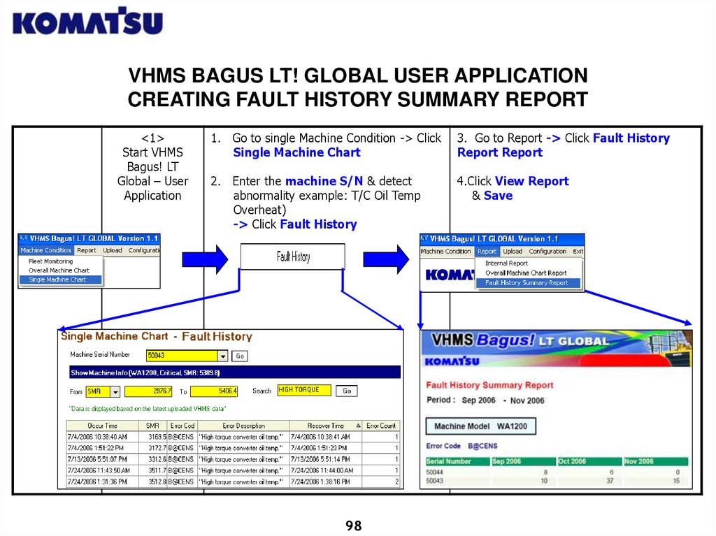
VHMS BAGUS LT! GLOBAL USER APPLICATIONCREATING FAULT HISTORY SUMMARY REPORT
<1>
Start VHMS
Bagus! LT
Global – User
Application
1. Go to single Machine Condition -> Click
Single Machine Chart
3. Go to Report -> Click Fault History
Report Report
2. Enter the machine S/N & detect
abnormality example: T/C Oil Temp
Overheat)
-> Click Fault History
4.Click View Report
& Save
98
99.
CHAPTER IIIVHMS Bagus! LT GLOBAL ADMIN
FUNCTION AND DATABASE
MAINTENANCE
99
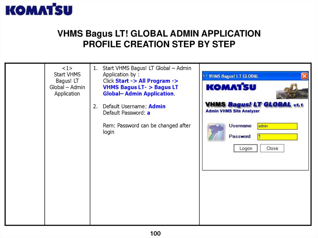
100.
VHMS Bagus LT! GLOBAL ADMIN APPLICATIONPROFILE CREATION STEP BY STEP
<1>
Start VHMS
Bagus! LT
Global – Admin
Application
1. Start VHMS Bagus! LT Global – Admin
Application by :
Click Start -> All Program ->
VHMS Bagus LT- > Bagus LT
Global– Admin Application.
2. Default Username: Admin
Default Password: a
Rem: Password can be changed after
login
100
101.
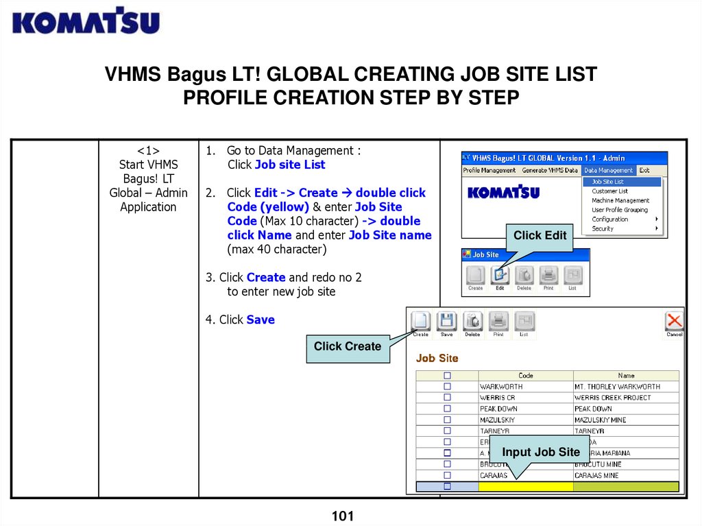
VHMS Bagus LT! GLOBAL CREATING JOB SITE LISTPROFILE CREATION STEP BY STEP
<1>
Start VHMS
Bagus! LT
Global – Admin
Application
1. Go to Data Management :
Click Job site List
2. Click Edit -> Create double click
Code (yellow) & enter Job Site
Code (Max 10 character) -> double
click Name and enter Job Site name
(max 40 character)
Click Edit
3. Click Create and redo no 2
to enter new job site
4. Click Save
Click Create
Input Job Site
101
102.
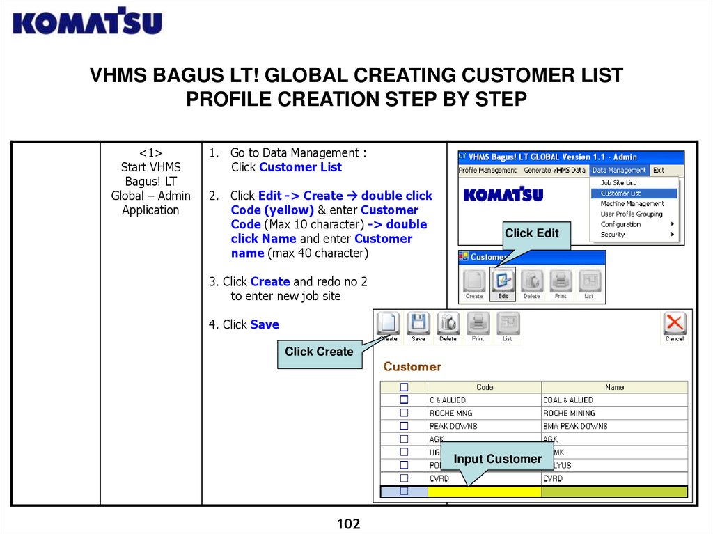
VHMS BAGUS LT! GLOBAL CREATING CUSTOMER LISTPROFILE CREATION STEP BY STEP
<1>
Start VHMS
Bagus! LT
Global – Admin
Application
1. Go to Data Management :
Click Customer List
2. Click Edit -> Create double click
Code (yellow) & enter Customer
Code (Max 10 character) -> double
click Name and enter Customer
name (max 40 character)
Click Edit
3. Click Create and redo no 2
to enter new job site
4. Click Save
Click Create
Input Customer
102
103.
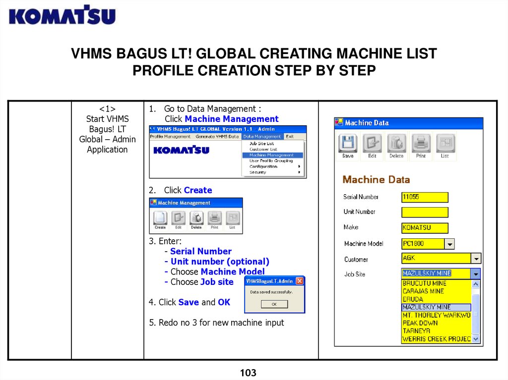
VHMS BAGUS LT! GLOBAL CREATING MACHINE LISTPROFILE CREATION STEP BY STEP
<1>
Start VHMS
Bagus! LT
Global – Admin
Application
1. Go to Data Management :
Click Machine Management
2. Click Create
3. Enter:
- Serial Number
- Unit number (optional)
- Choose Machine Model
- Choose Job site
4. Click Save and OK
5. Redo no 3 for new machine input
103
104.
VHMS BAGUS LT! GLOBAL CREATING USER PROFILE GROUPINGPROFILE CREATION STEP BY STEP
<1>
Start VHMS
Bagus! LT
Global – Admin
Application
1. Go to Data Management :
Click User Profile Grouping
2. Click Edit -> Create double click
Code (yellow) & enter Code (Max 10
character) -> double click Name and
enter Description (max 40 character)
Click Edit
3. Click Save
Click Create
Input User Group Name
104
105.
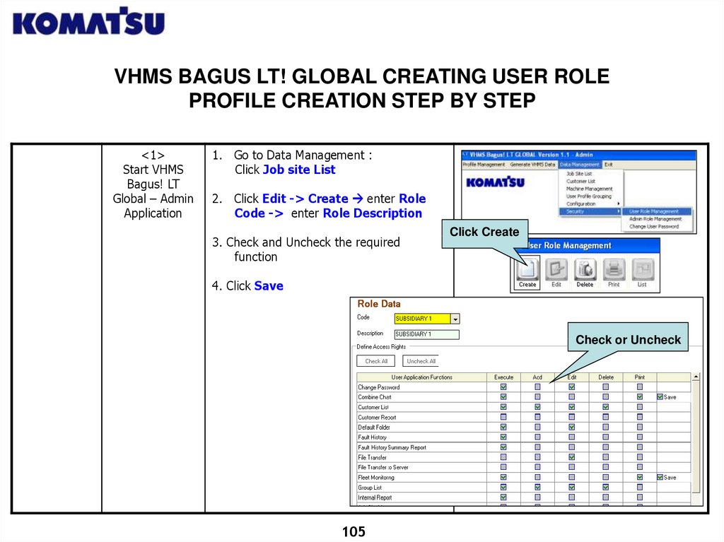
VHMS BAGUS LT! GLOBAL CREATING USER ROLEPROFILE CREATION STEP BY STEP
<1>
Start VHMS
Bagus! LT
Global – Admin
Application
1. Go to Data Management :
Click Job site List
2. Click Edit -> Create enter Role
Code -> enter Role Description
3. Check and Uncheck the required
function
Click Create
4. Click Save
Check or Uncheck
105
106.
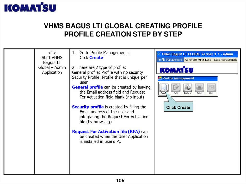
VHMS BAGUS LT! GLOBAL CREATING PROFILEPROFILE CREATION STEP BY STEP
<1>
Start VHMS
Bagus! LT
Global – Admin
Application
1. Go to Profile Management :
Click Create
2. There are 2 type of profile:
General profile: Profile with no security
Security Profile: Profile that is unique per
user
General profile can be created by leaving
the Email address field and Request
For Activation field blank (no input)
Security profile is created by filling the
Email address of the user and
integrating the Request For Activation
file (by browsing)
Request For Activation file (RFA) can
be created when the User Application
is installed in user’s PC
106
Click Create
107.
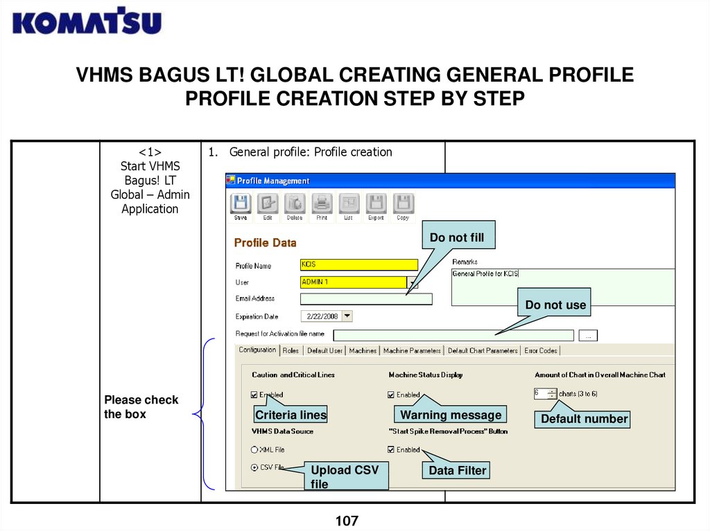
VHMS BAGUS LT! GLOBAL CREATING GENERAL PROFILEPROFILE CREATION STEP BY STEP
<1>
Start VHMS
Bagus! LT
Global – Admin
Application
1. General profile: Profile creation
Do not fill
Do not use
Please check
the box
Criteria lines
Warning message
Upload CSV
file
107
Data Filter
Default number
108.
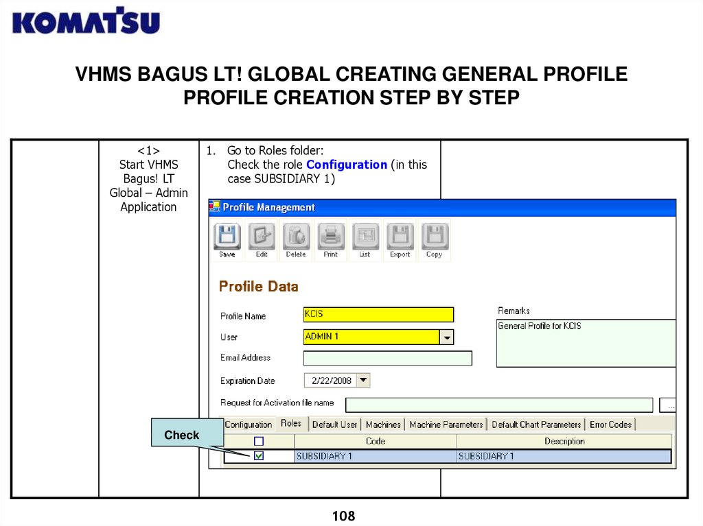
VHMS BAGUS LT! GLOBAL CREATING GENERAL PROFILEPROFILE CREATION STEP BY STEP
<1>
Start VHMS
Bagus! LT
Global – Admin
Application
1. Go to Roles folder:
Check the role Configuration (in this
case SUBSIDIARY 1)
Check
108
109.
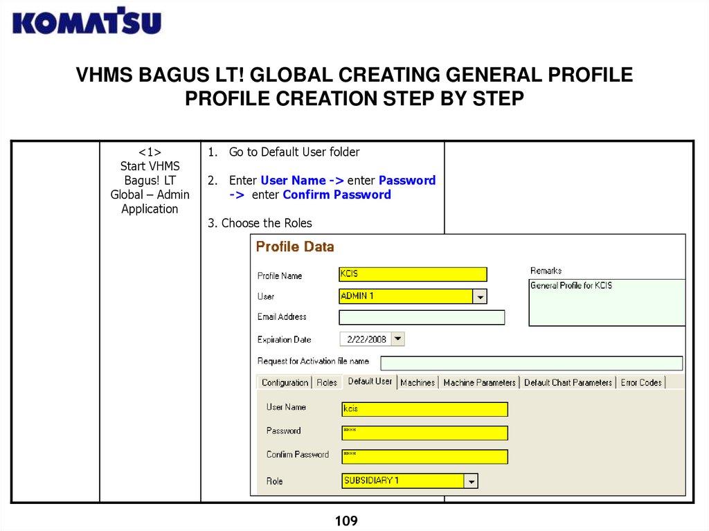
VHMS BAGUS LT! GLOBAL CREATING GENERAL PROFILEPROFILE CREATION STEP BY STEP
<1>
Start VHMS
Bagus! LT
Global – Admin
Application
1. Go to Default User folder
2. Enter User Name -> enter Password
-> enter Confirm Password
3. Choose the Roles
109
110.
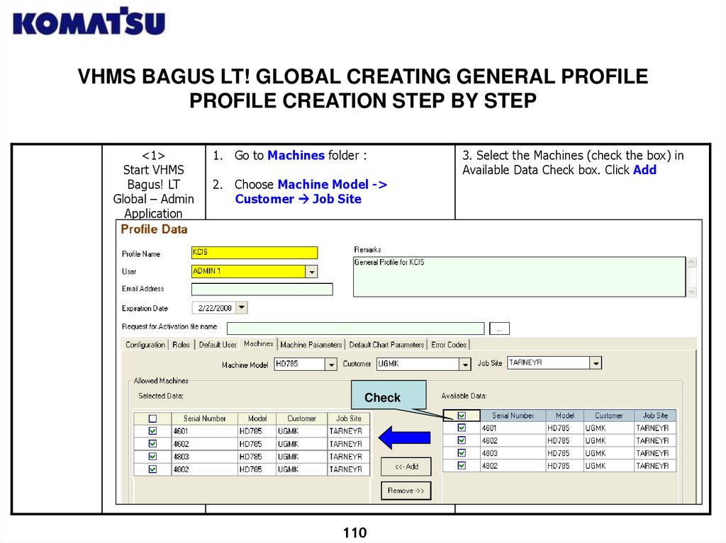
VHMS BAGUS LT! GLOBAL CREATING GENERAL PROFILEPROFILE CREATION STEP BY STEP
<1>
Start VHMS
Bagus! LT
Global – Admin
Application
1. Go to Machines folder :
2. Choose Machine Model ->
Customer Job Site
Check
110
3. Select the Machines (check the box) in
Available Data Check box. Click Add
111.
VHMS BAGUS LT! GLOBAL CREATING PROFILEPROFILE CREATION STEP BY STEP
<1>
Start VHMS
Bagus! LT
Global – Admin
Application
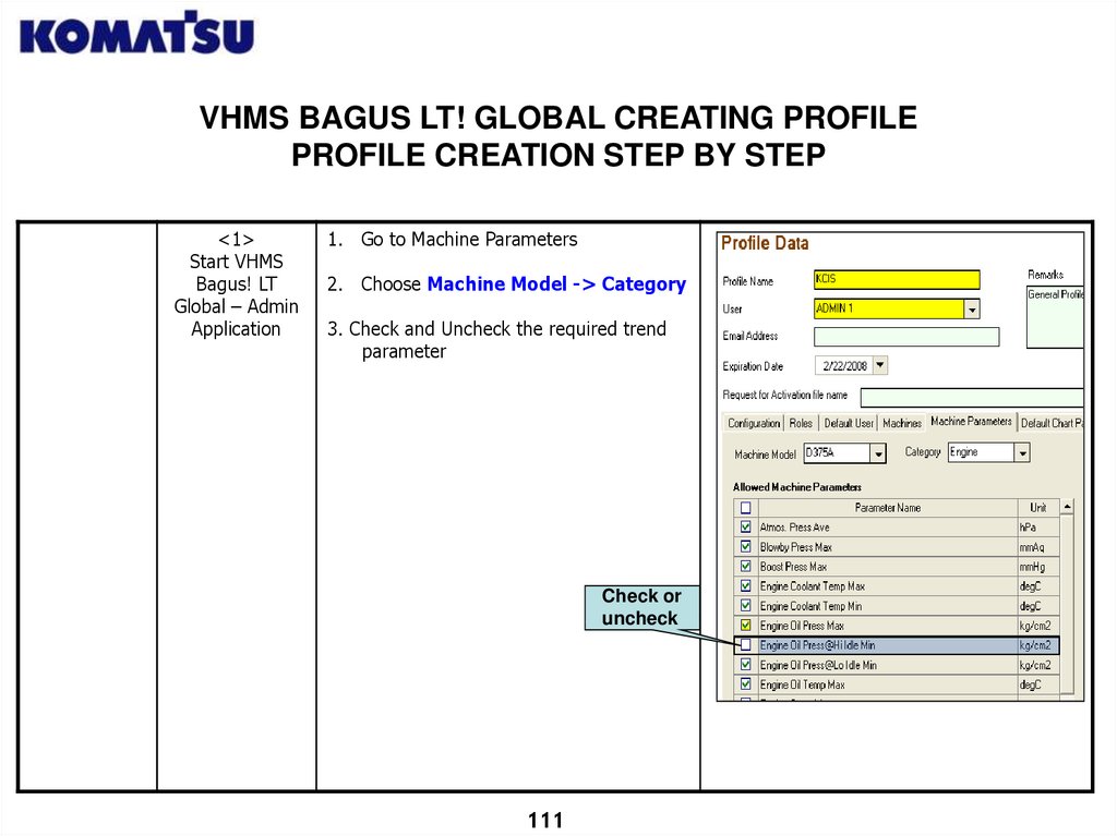
1. Go to Machine Parameters
2. Choose Machine Model -> Category
3. Check and Uncheck the required trend
parameter
Check or
uncheck
111
112.
VHMS BAGUS LT! GLOBAL CREATING PROFILEPROFILE CREATION STEP BY STEP
<1>
Start VHMS
Bagus! LT
Global – Admin
Application
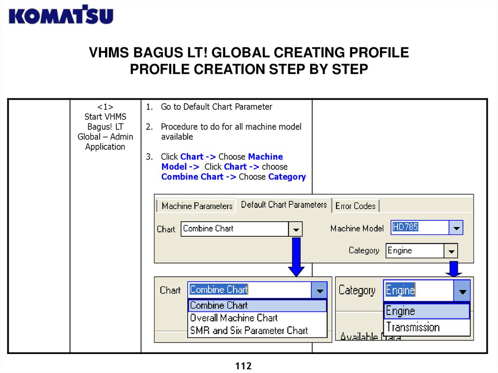
1. Go to Default Chart Parameter
2. Procedure to do for all machine model
available
3. Click Chart -> Choose Machine
Model -> Click Chart -> choose
Combine Chart -> Choose Category
112
113.
VHMS BAGUS LT! GLOBAL CREATING GENERAL PROFILEPROFILE CREATION STEP BY STEP
<1>
Start VHMS
Bagus! LT
Global – Admin
Application
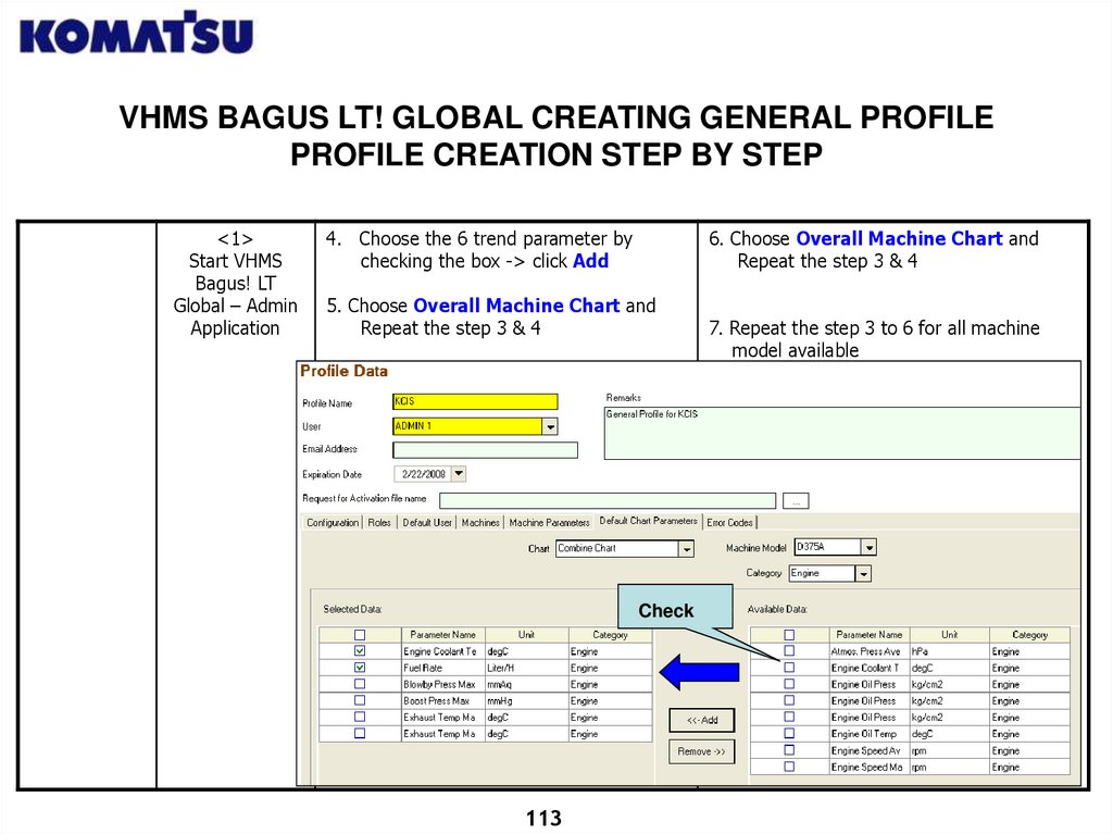
4. Choose the 6 trend parameter by
checking the box -> click Add
6. Choose Overall Machine Chart and
Repeat the step 3 & 4
5. Choose Overall Machine Chart and
Repeat the step 3 & 4
Check
113
7. Repeat the step 3 to 6 for all machine
model available
114.
VHMS BAGUS LT! GLOBAL CREATING GENERAL PROFILEPROFILE CREATION STEP BY STEP
<1>
Start VHMS
Bagus! LT
Global – Admin
Application
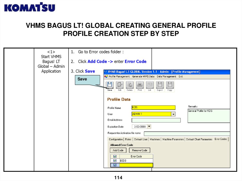
1. Go to Error codes folder :
2. Click Add Code -> enter Error Code
3. Click Save
Save
114
115.
UPDATE USER PROFILE AND TECHNICAL PARAMETER TOVHMS BAGUS DATABASE
VHMS Bagus LT User Profile & Technical Parameter Process Update is
performed when changes happen to VHMS Bagus LT – User Application
user profile and technical parameter.
Changes to User Profile :
1. Population change
2. User Role change
Changes to Technical Parameter :
1. Caution and Critical Line Value change
2. Quantity of machine parameter change
This change will be done by VHMS LT Administrator. Afterwards
Administrator will send an Update Profile / Technical Parameter File to
each VHMS LT User. Each User is obliged to upload the file into VHMS LT
User application.
115
116.
UPDATE USER PROFILE TO VHMS BAGUS DATABASE<1>
Start VHMS
Bagus LT – User
Application
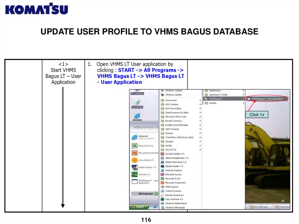
1. Open VHMS LT User application by
clicking : START -> All Programs ->
VHMS Bagus LT -> VHMS Bagus LT
- User Application
Click 1x
116
117.
UPDATE USER PROFILE TO VHMS BAGUS DATABASE<2>
Insert
Username and
Password
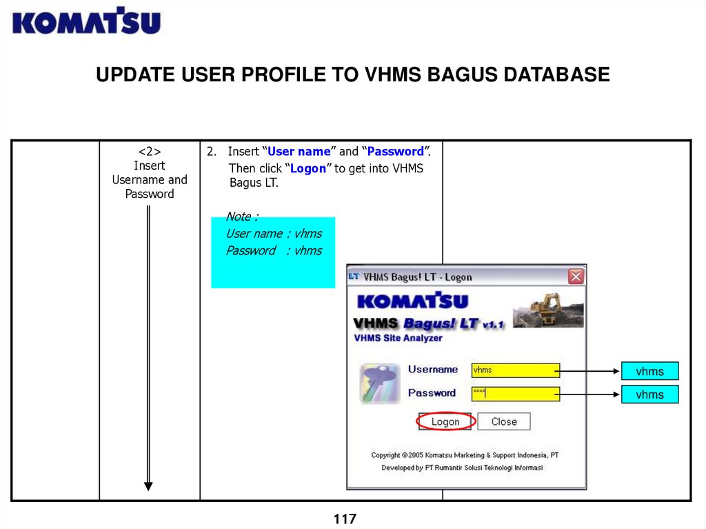
2. Insert “User name” and “Password”.
Then click “Logon” to get into VHMS
Bagus LT.
Note :
User name : vhms
Password : vhms
vhms
vhms
117
118.
UPDATE USER PROFILE TO VHMS BAGUS DATABASE<3>
VHMS Bagus
LT– User
Application Main
Menu Display
3. VHMS Bagus LT User Application Main
Menu will open.
118
119.
UPDATE USER PROFILE TO VHMS BAGUS DATABASE<4>
Open User
Profile Upload
process
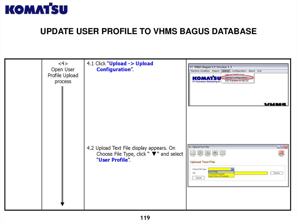
4.1 Click “Upload -> Upload
Configuration”.
4.2 Upload Text File display appears. On
Choose File Type, click “
“ and select
“User Profile”.
119
120.
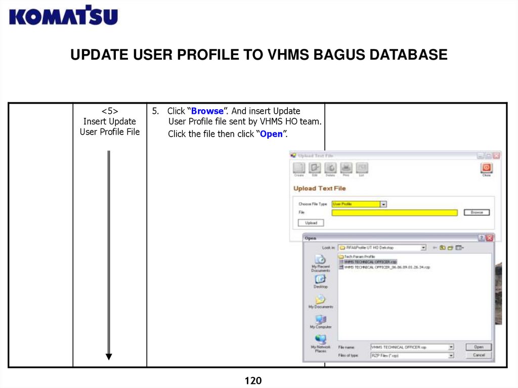
UPDATE USER PROFILE TO VHMS BAGUS DATABASE<5>
Insert Update
User Profile File
5. Click “Browse”. And insert Update
User Profile file sent by VHMS HO team.
Click the file then click “Open”.
120
121.
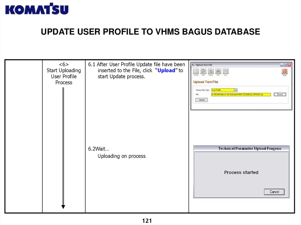
UPDATE USER PROFILE TO VHMS BAGUS DATABASE<6>
Start Uploading
User Profile
Process
6.1 After User Profile Update file have been
inserted to the File, click “Upload” to
start Update process.
6.2Wait…
Uploading on process
121
122.
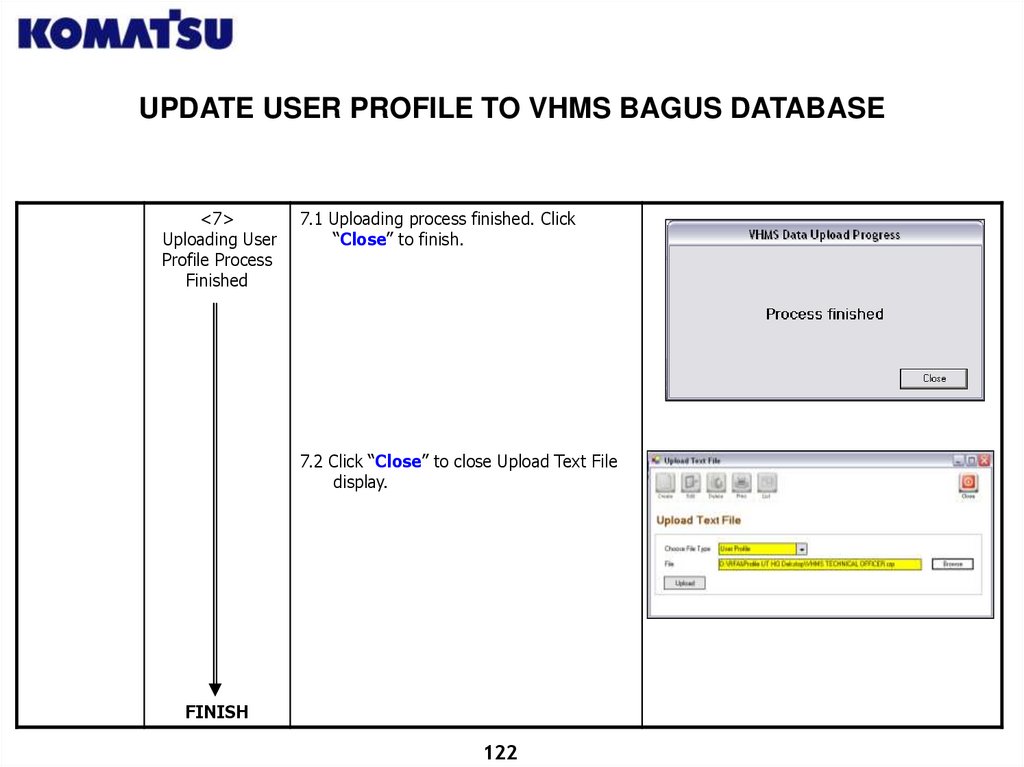
UPDATE USER PROFILE TO VHMS BAGUS DATABASE<7>
Uploading User
Profile Process
Finished
7.1 Uploading process finished. Click
“Close” to finish.
7.2 Click “Close” to close Upload Text File
display.
FINISH
122
123.
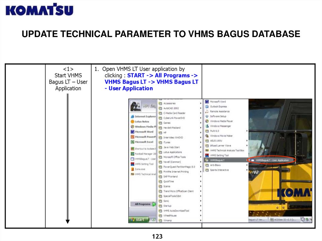
UPDATE TECHNICAL PARAMETER TO VHMS BAGUS DATABASE<1>
Start VHMS
Bagus LT – User
Application
1. Open VHMS LT User application by
clicking : START -> All Programs ->
VHMS Bagus LT -> VHMS Bagus LT
- User Application
123
124.
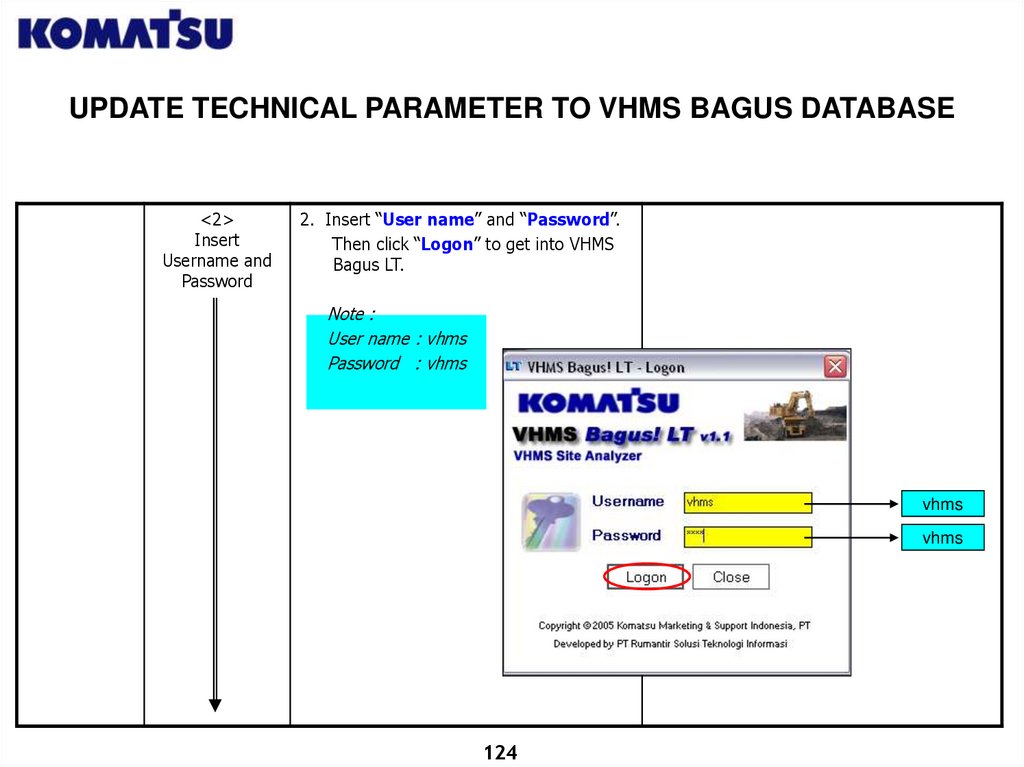
UPDATE TECHNICAL PARAMETER TO VHMS BAGUS DATABASE<2>
Insert
Username and
Password
2. Insert “User name” and “Password”.
Then click “Logon” to get into VHMS
Bagus LT.
Note :
User name : vhms
Password : vhms
vhms
vhms
124
125.
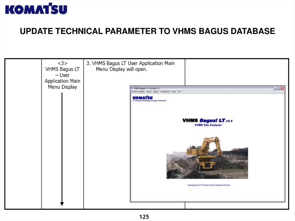
UPDATE TECHNICAL PARAMETER TO VHMS BAGUS DATABASE<3>
VHMS Bagus LT
– User
Application Main
Menu Display
3. VHMS Bagus LT User Application Main
Menu Display will open.
125
126.
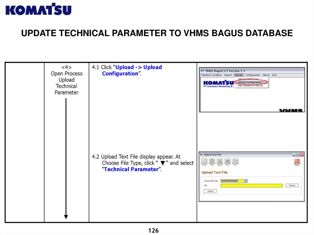
UPDATE TECHNICAL PARAMETER TO VHMS BAGUS DATABASE<4>
Open Process
Upload
Technical
Parameter
4.1 Click “Upload -> Upload
Configuration”.
4.2 Upload Text File display appear. At
Choose File Type, click “
“ and select
“Technical Parameter”.
126
127.
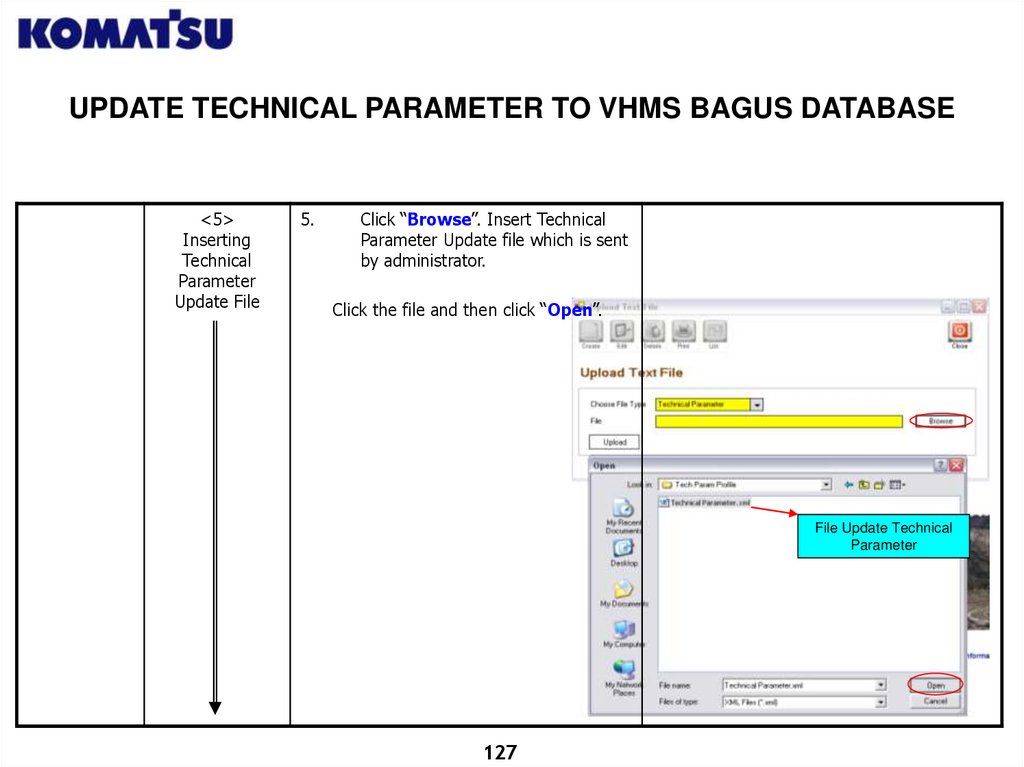
UPDATE TECHNICAL PARAMETER TO VHMS BAGUS DATABASE<5>
Inserting
Technical
Parameter
Update File
5.
Click “Browse”. Insert Technical
Parameter Update file which is sent
by administrator.
Click the file and then click “Open”.
File Update Technical
Parameter
127
128.
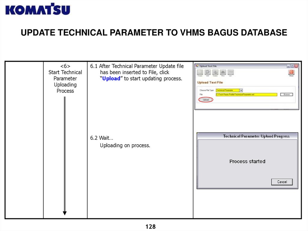
UPDATE TECHNICAL PARAMETER TO VHMS BAGUS DATABASE<6>
Start Technical
Parameter
Uploading
Process
6.1 After Technical Parameter Update file
has been inserted to File, click
“Upload” to start updating process.
6.2 Wait…
Uploading on process.
128
129.
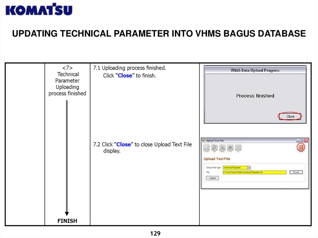
UPDATING TECHNICAL PARAMETER INTO VHMS BAGUS DATABASE<7>
Technical
Parameter
Uploading
process finished
7.1 Uploading process finished.
Click “Close” to finish.
7.2 Click “Close” to close Upload Text File
display.
FINISH
129
130.
VHMS BAGUS LT! GLOBAL USER APPLICATIONPRECAUTION DELETING MACHINE
<1>
Start VHMS
Bagus! LT
Global – User
Application
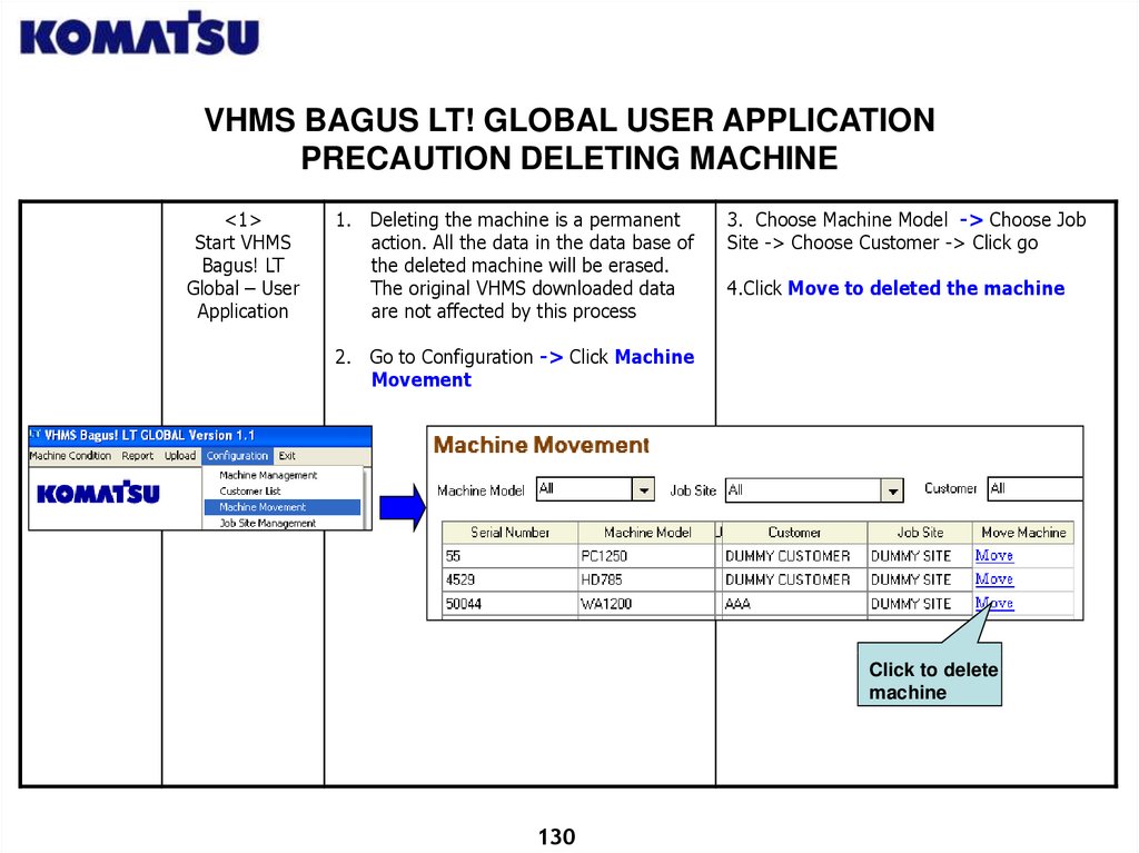
1. Deleting the machine is a permanent
action. All the data in the data base of
the deleted machine will be erased.
The original VHMS downloaded data
are not affected by this process
3. Choose Machine Model -> Choose Job
Site -> Choose Customer -> Click go
4.Click Move to deleted the machine
2. Go to Configuration -> Click Machine
Movement
Click to delete
machine
130
131.
VHMS BAGUS LT! GLOBAL USER APPLICATIONPRECAUTION – DATA BASE MAINTENANCE & BACK UP
<1>
Start VHMS
Bagus! LT
Global – User
Application
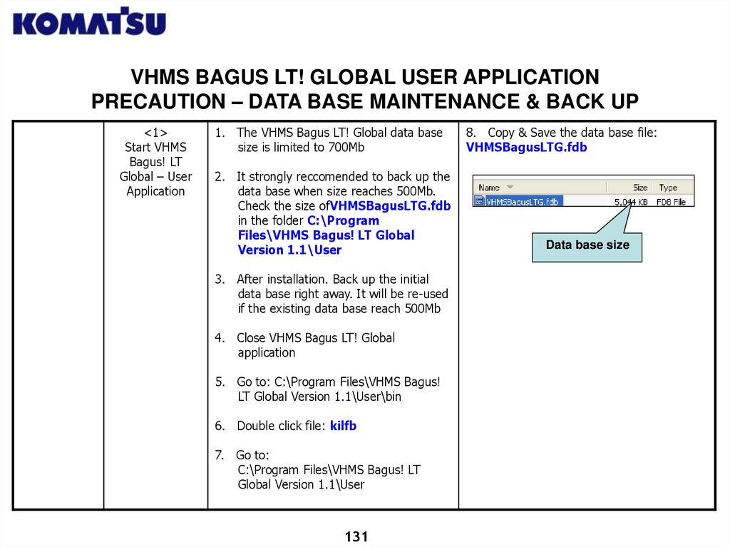
1. The VHMS Bagus LT! Global data base
size is limited to 700Mb
2. It strongly reccomended to back up the
data base when size reaches 500Mb.
Check the size ofVHMSBagusLTG.fdb
in the folder C:\Program
Files\VHMS Bagus! LT Global
Version 1.1\User
3. After installation. Back up the initial
data base right away. It will be re-used
if the existing data base reach 500Mb
4. Close VHMS Bagus LT! Global
application
5. Go to: C:\Program Files\VHMS Bagus!
LT Global Version 1.1\User\bin
6. Double click file: kilfb
7. Go to:
C:\Program Files\VHMS Bagus! LT
Global Version 1.1\User
131
8. Copy & Save the data base file:
VHMSBagusLTG.fdb
Data base size
132.
VHMS BAGUS LT! GLOBAL USER APPLICATIONPRECAUTION – DATA BASE MAINTENANCE & BACK UP
<1>
Start VHMS
Bagus! LT
Global – User
Application
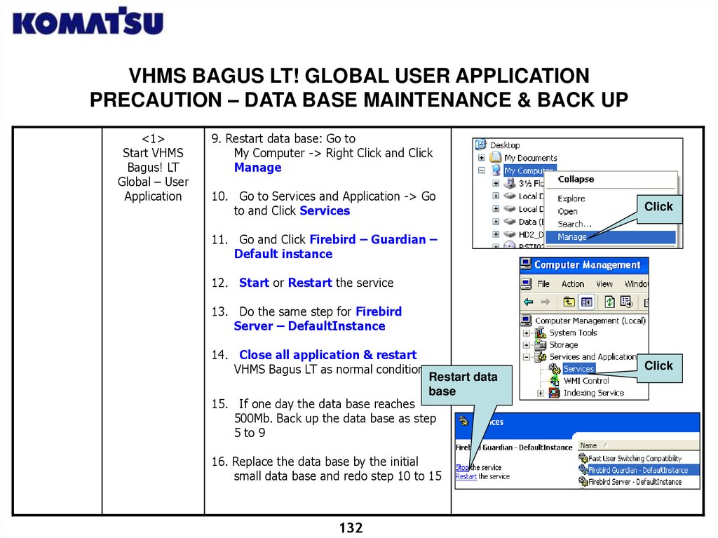
9. Restart data base: Go to
My Computer -> Right Click and Click
Manage
10. Go to Services and Application -> Go
to and Click Services
Click
11. Go and Click Firebird – Guardian –
Default instance
12. Start or Restart the service
13. Do the same step for Firebird
Server – DefaultInstance
14. Close all application & restart
VHMS Bagus LT as normal condition
Click
Restart data
base
15. If one day the data base reaches
500Mb. Back up the data base as step
5 to 9
16. Replace the data base by the initial
small data base and redo step 10 to 15
132
133.
CHAPTER IVPLM II
133
134.
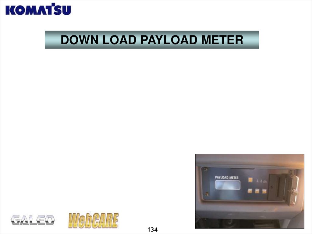
DOWN LOAD PAYLOAD METER134
135.
DOWNLOAD PLM II USING LAPTOPPayload Meter Downloading using Laptop definition :
A process to copy data from PLM II Controller ( Memory Card Type) into
Laptop, which can be done from inside or outside cabin ( Remote Box /
Ground Level Connector ).
Downloading PLM from outside cabin until July 2006 can only be performed
on HD465/605-7 and HD785-7 units.
General Objectives :
To determine the Machine Operation and Production data.
Data copied among others are maximum data load for each cycle, maximum
speed for each cycle, etc. related to production.
Note :
Maximum PLM Data memory capacity in VHMS Controller is 1000 cycle. If
after reaching 1000 cycle no download is performed, then the new data cycle
cannot be recorded or VHMS Controller cannot store data from PLM II
Controller .
PLM II Controller alone has memory to store PLM Data. When PLM II
Controller memory is full, then in PLM display an error code will appear for
Data FULL (E.FUL, F. FUL, L.FUL or H.FUL).
After download, PLM II Controller memory should be erased.
135
136.
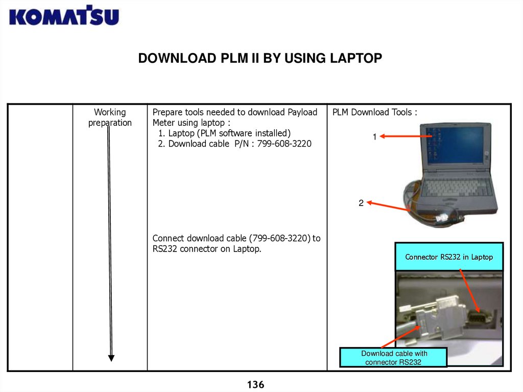
DOWNLOAD PLM II BY USING LAPTOPWorking
preparation
Prepare tools needed to download Payload
Meter using laptop :
1. Laptop (PLM software installed)
2. Download cable P/N : 799-608-3220
PLM Download Tools :
1
2
Connect download cable (799-608-3220) to
RS232 connector on Laptop.
Connector RS232 in Laptop
Download cable with
connector RS232
136
137.
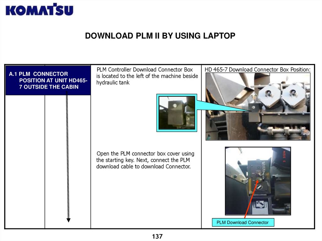
DOWNLOAD PLM II BY USING LAPTOPA.1 PLM CONNECTOR
POSITION AT UNIT HD4657 OUTSIDE THE CABIN
PLM Controller Download Connector Box
is located to the left of the machine beside
hydraulic tank
HD 465-7 Download Connector Box Position:
Open the PLM connector box cover using
the starting key. Next, connect the PLM
download cable to download Connector.
PLM Download Connector
137
138.
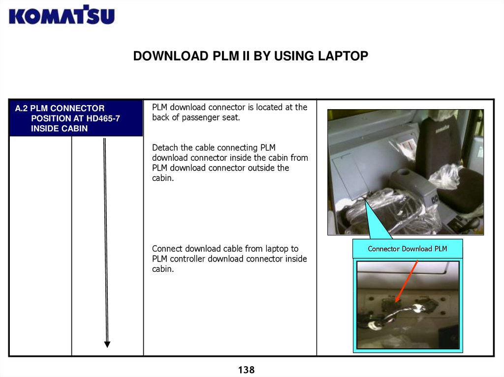
DOWNLOAD PLM II BY USING LAPTOPA.2 PLM CONNECTOR
POSITION AT HD465-7
INSIDE CABIN
PLM download connector is located at the
back of passenger seat.
Detach the cable connecting PLM
download connector inside the cabin from
PLM download connector outside the
cabin.
Connect download cable from laptop to
PLM controller download connector inside
cabin.
138
Connector Download PLM
139.
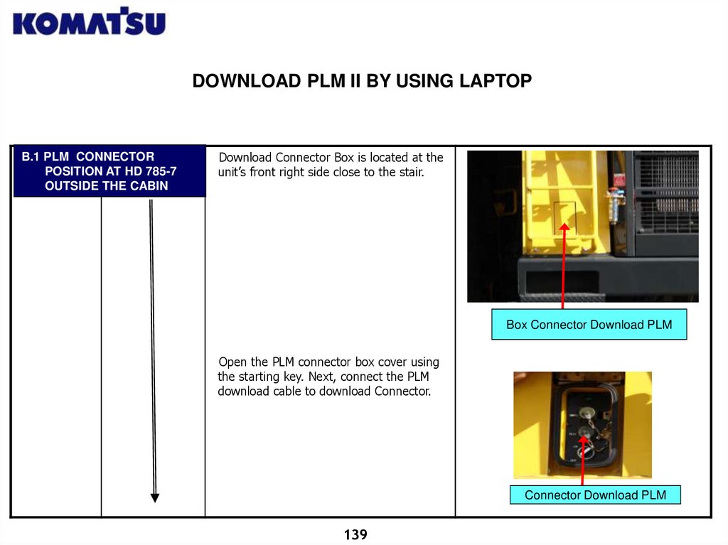
DOWNLOAD PLM II BY USING LAPTOPB.1 PLM CONNECTOR
POSITION AT HD 785-7
OUTSIDE THE CABIN
Download Connector Box is located at the
unit’s front right side close to the stair.
Box Connector Download PLM
Open the PLM connector box cover using
the starting key. Next, connect the PLM
download cable to download Connector.
Connector Download PLM
139
140.
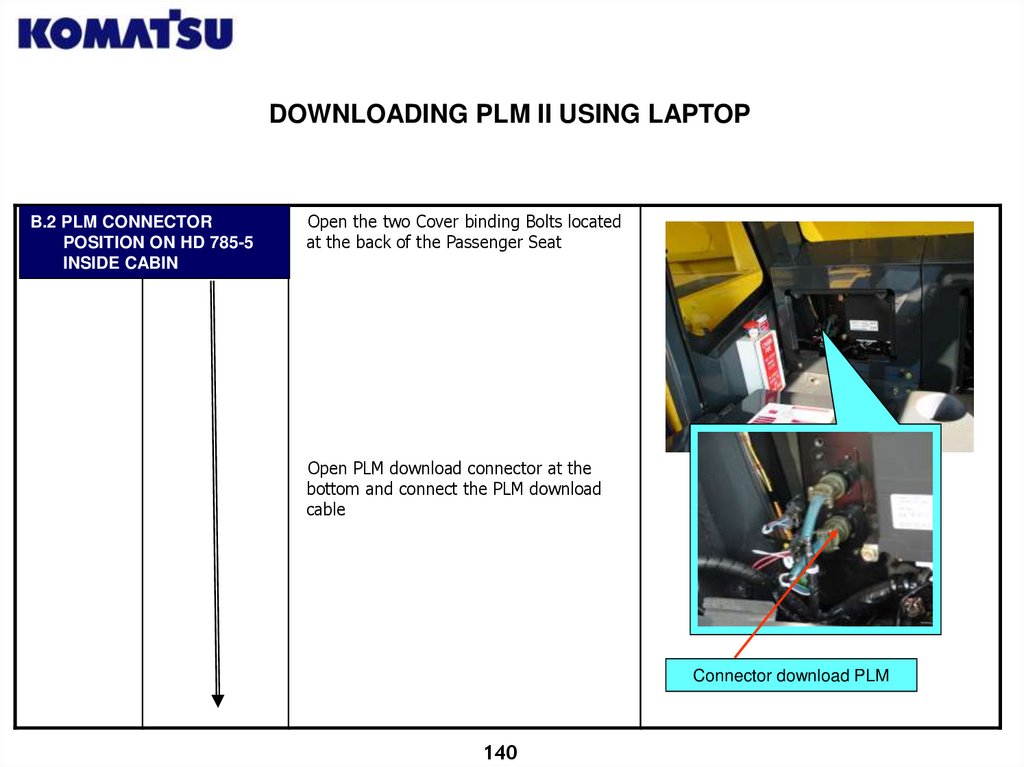
DOWNLOADING PLM II USING LAPTOPB.2 PLM CONNECTOR
POSITION ON HD 785-5
INSIDE CABIN
Open the two Cover binding Bolts located
at the back of the Passenger Seat
Open PLM download connector at the
bottom and connect the PLM download
cable
Connector download PLM
140
141.
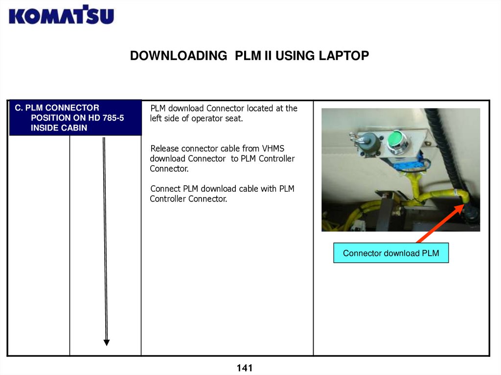
DOWNLOADING PLM II USING LAPTOPC. PLM CONNECTOR
POSITION ON HD 785-5
INSIDE CABIN
PLM download Connector located at the
left side of operator seat.
Release connector cable from VHMS
download Connector to PLM Controller
Connector.
Connect PLM download cable with PLM
Controller Connector.
Connector download PLM
141
142.
DOWNLOADING PLM II USING LAPTOPKey Switch
OFF
<1>
Start PLM
Version 1.6
Application
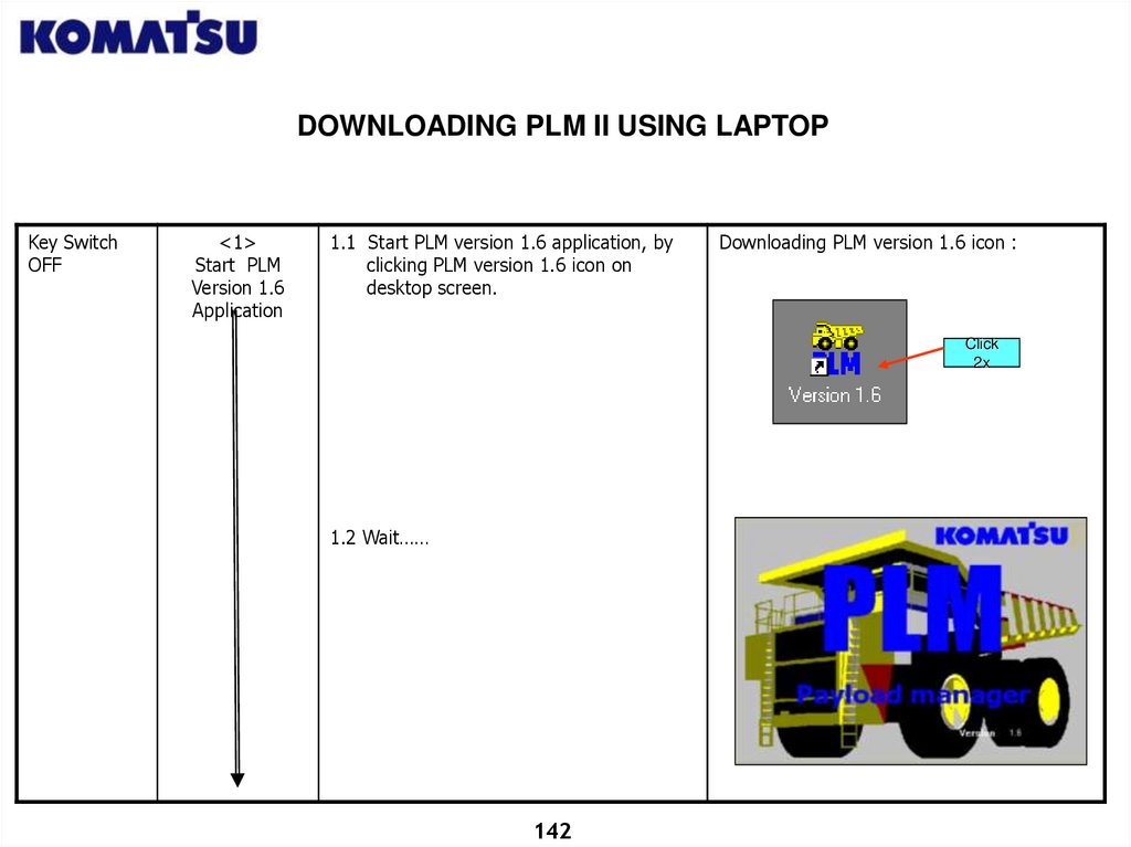
1.1 Start PLM version 1.6 application, by
clicking PLM version 1.6 icon on
desktop screen.
Downloading PLM version 1.6 icon :
Click
2x
1.2 Wait……
142
143.
DOWNLOADING PLM II USING LAPTOPKey Switch
OFF
<2>
Choose PLM
Downloading
Method to use
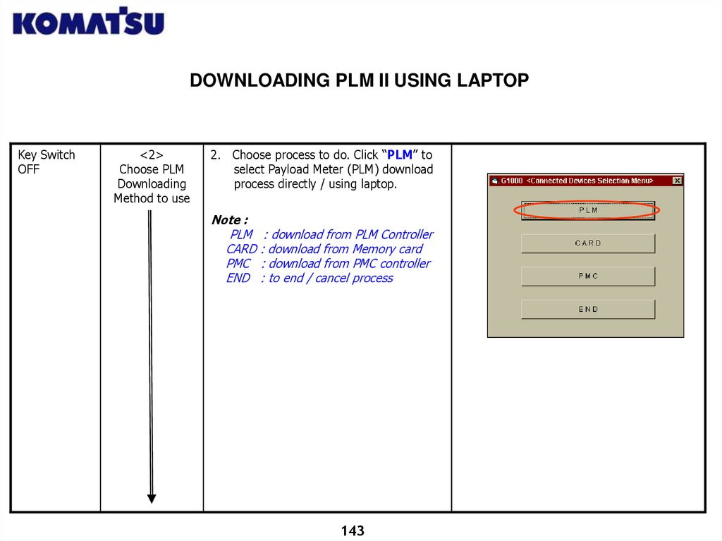
2. Choose process to do. Click “PLM” to
select Payload Meter (PLM) download
process directly / using laptop.
Note :
PLM
CARD
PMC
END
: download from PLM Controller
: download from Memory card
: download from PMC controller
: to end / cancel process
143
144.
DOWNLOADING PLM II USING LAPTOPKey Switch
OFF
<3>
Set Parameter
Download PLM
Setting
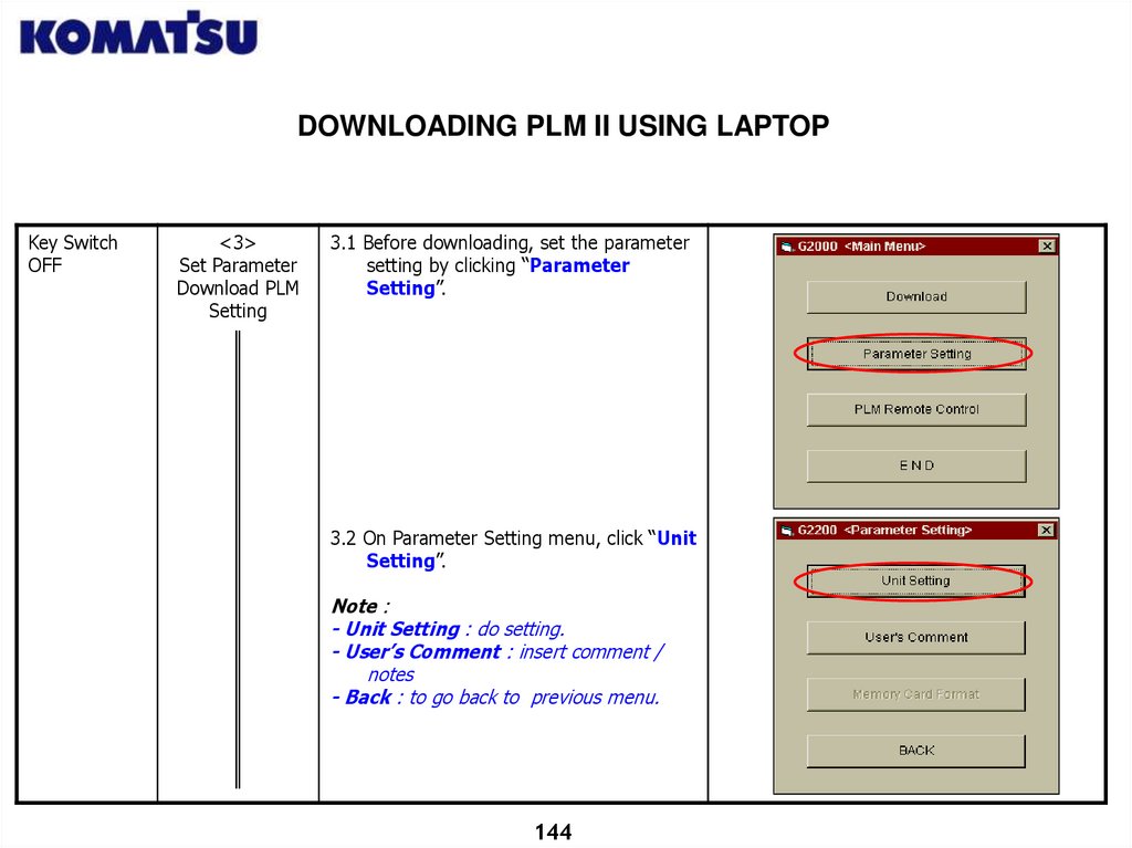
3.1 Before downloading, set the parameter
setting by clicking “Parameter
Setting”.
3.2 On Parameter Setting menu, click “Unit
Setting”.
Note :
- Unit Setting : do setting.
- User’s Comment : insert comment /
notes
- Back : to go back to previous menu.
144
145.
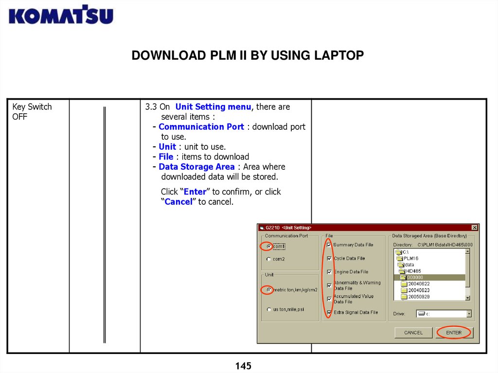
DOWNLOAD PLM II BY USING LAPTOPKey Switch
OFF
3.3 On Unit Setting menu, there are
several items :
- Communication Port : download port
to use.
- Unit : unit to use.
- File : items to download
- Data Storage Area : Area where
downloaded data will be stored.
Click “Enter” to confirm, or click
“Cancel” to cancel.
145
146.
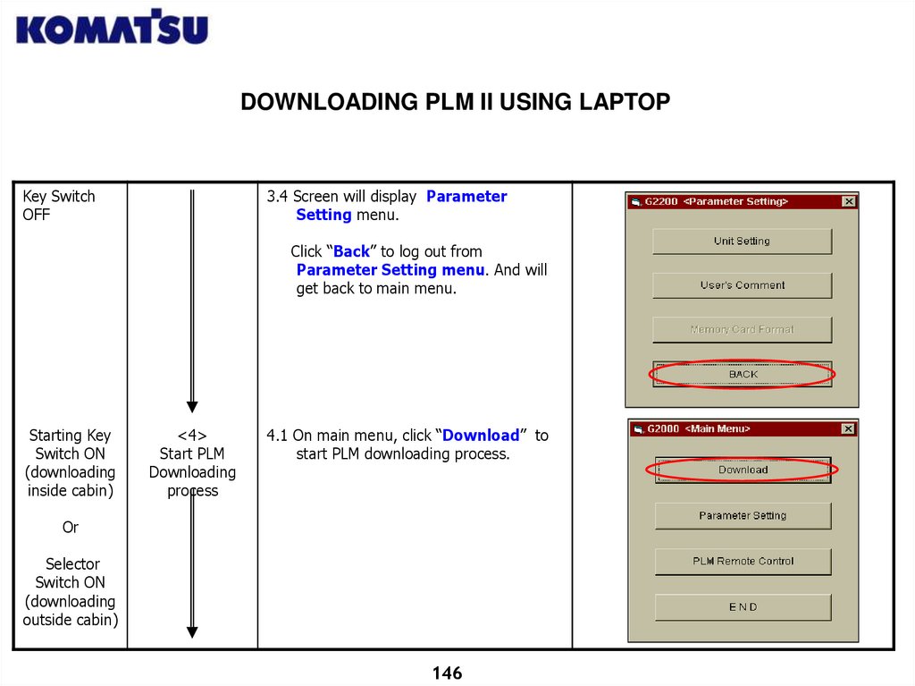
DOWNLOADING PLM II USING LAPTOPKey Switch
OFF
3.4 Screen will display Parameter
Setting menu.
Click “Back” to log out from
Parameter Setting menu. And will
get back to main menu.
Starting Key
Switch ON
(downloading
inside cabin)
<4>
Start PLM
Downloading
process
4.1 On main menu, click “Download” to
start PLM downloading process.
Or
Selector
Switch ON
(downloading
outside cabin)
146
147.
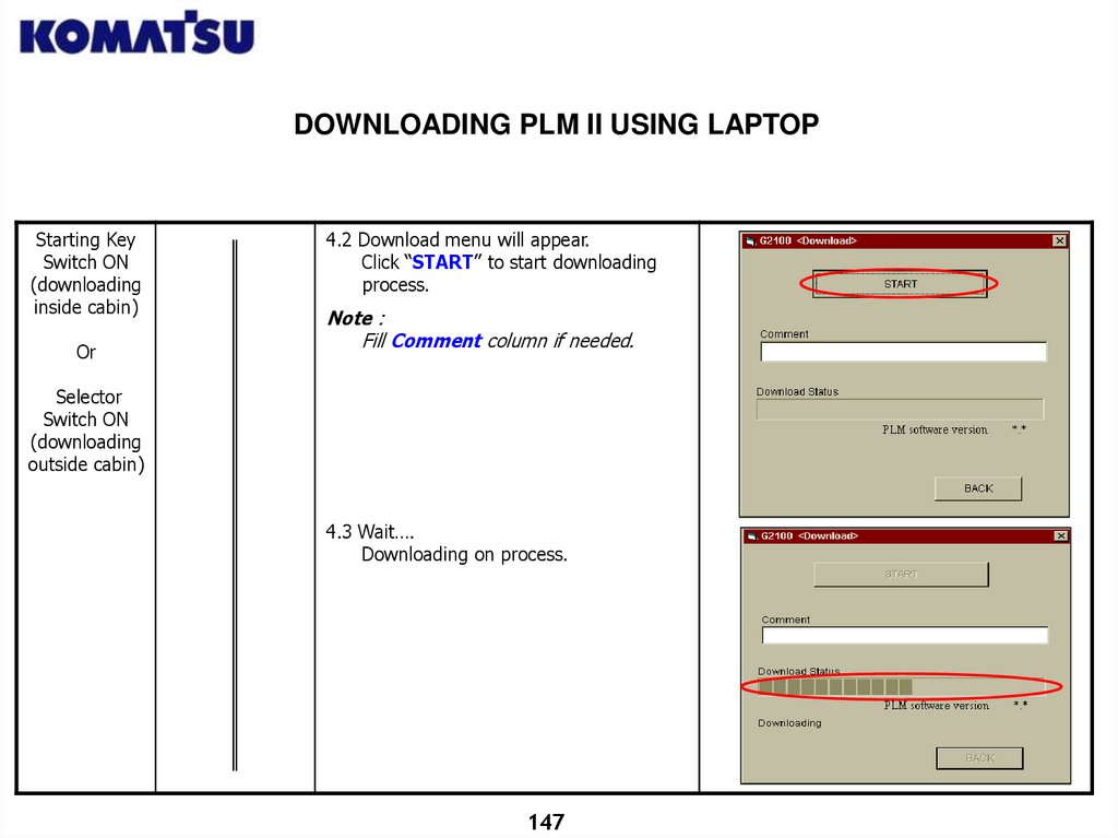
DOWNLOADING PLM II USING LAPTOPStarting Key
Switch ON
(downloading
inside cabin)
Or
4.2 Download menu will appear.
Click “START” to start downloading
process.
Note :
Fill Comment column if needed.
Selector
Switch ON
(downloading
outside cabin)
4.3 Wait….
Downloading on process.
147
148.
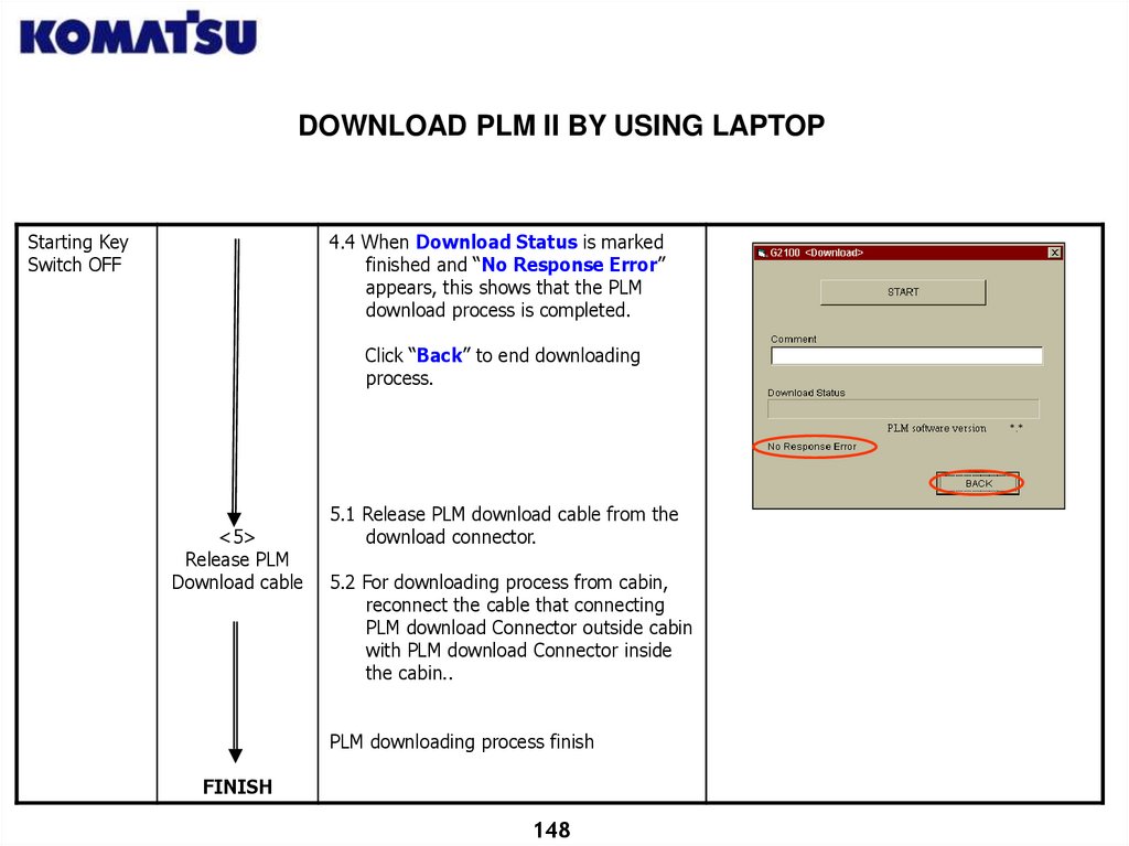
DOWNLOAD PLM II BY USING LAPTOPStarting Key
Switch OFF
4.4 When Download Status is marked
finished and “No Response Error”
appears, this shows that the PLM
download process is completed.
Click “Back” to end downloading
process.
<5>
Release PLM
Download cable
5.1 Release PLM download cable from the
download connector.
5.2 For downloading process from cabin,
reconnect the cable that connecting
PLM download Connector outside cabin
with PLM download Connector inside
the cabin..
PLM downloading process finish
FINISH
148
149.
DOWNLOAD PLM II USING MEMORY CARDDownload PLM Definition:
A process to copy data from PLM II Controller into Memory Card. Downloading
PLM using Memory Card cannot be used on New HD785-7 ( PLM Controller
integrated with VHMS Controller )
General Purpose :
To get Machine Operation and Production data.
Data copied are maximum load per cycle, maximum speed per cycle, etc related to
production.
Notes :
Maximum capacity of PLM Data memory is 1000 cycles. If after reaching 1000 cycles
no downloading is performed, the new cycle data cannot be recorded or VHMS
Controller cannot store data from PLM II Controller.
PLM II Controller itself has memory to store. When PLM II Controller memory full,
an error code for Data FULL (E.FUL, F.FUL L.FUL or H.FUL) will appear on the
payload meter display.
After downloading, PLM II Controller memory must be deleted.
149
150.
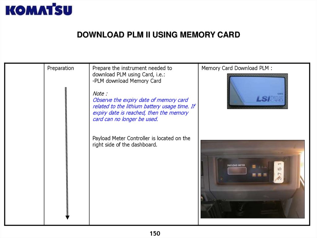
DOWNLOAD PLM II USING MEMORY CARDPreparation
Prepare the instrument needed to
download PLM using Card, i.e.:
-PLM download Memory Card
Note :
Observe the expiry date of memory card
related to the lithium battery usage time. If
expiry date is reached, then the memory
card can no longer be used.
Payload Meter Controller is located on the
right side of the dashboard.
150
Memory Card Download PLM :
151.
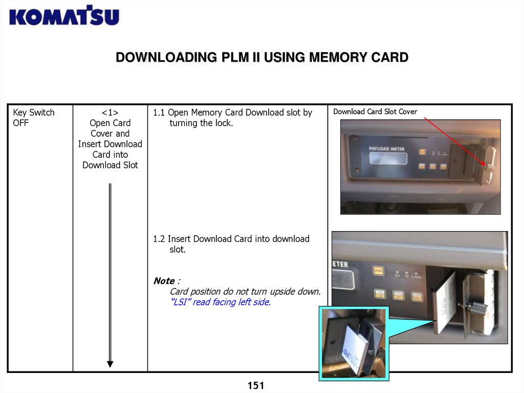
DOWNLOADING PLM II USING MEMORY CARDKey Switch
OFF
<1>
Open Card
Cover and
Insert Download
Card into
Download Slot
1.1 Open Memory Card Download slot by
turning the lock.
1.2 Insert Download Card into download
slot.
Note :
Card position do not turn upside down.
“LSI” read facing left side.
151
Download Card Slot Cover
152.
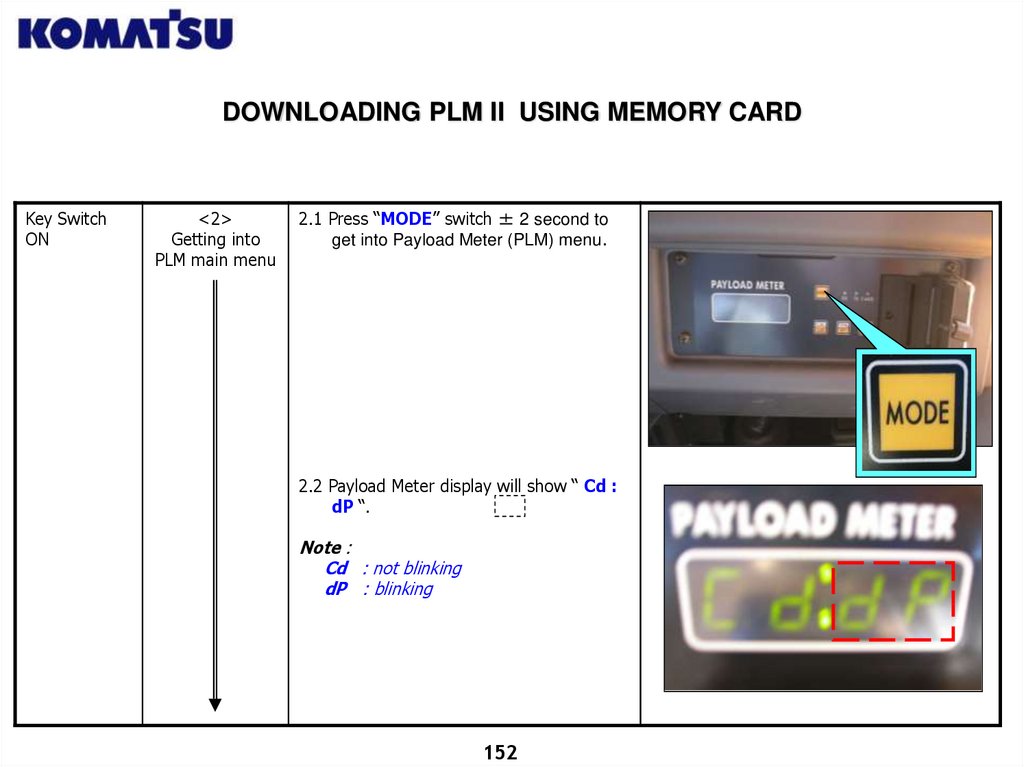
DOWNLOADING PLM II USING MEMORY CARDKey Switch
ON
<2>
Getting into
PLM main menu
2.1 Press “MODE” switch ± 2 second to
get into Payload Meter (PLM) menu.
2.2 Payload Meter display will show “ Cd :
dP “.
Note :
Cd : not blinking
dP : blinking
152
153.
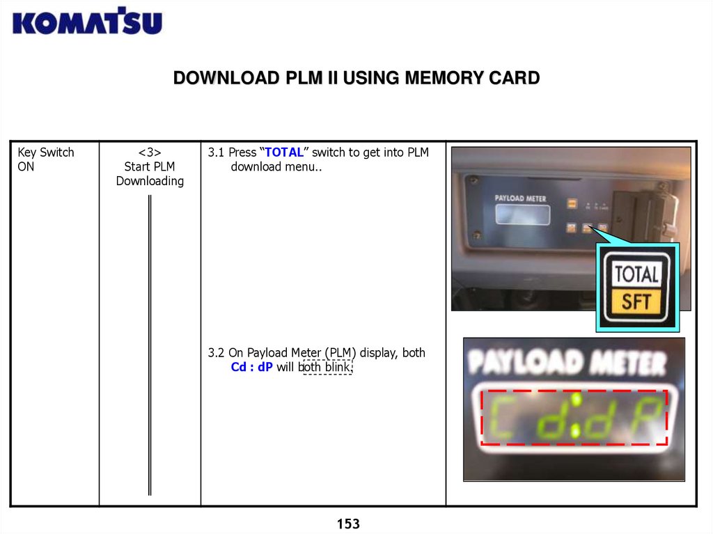
DOWNLOAD PLM II USING MEMORY CARDKey Switch
ON
<3>
Start PLM
Downloading
3.1 Press “TOTAL” switch to get into PLM
download menu..
3.2 On Payload Meter (PLM) display, both
Cd : dP will both blink.
153
154.
DOWNLOAD PLM II USING MEMORY CARDKey Switch
ON
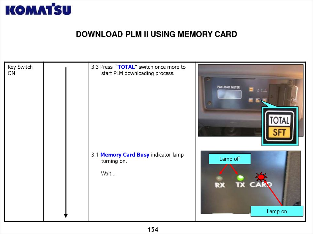
3.3 Press “TOTAL” switch once more to
start PLM downloading process.
3.4 Memory Card Busy indicator lamp
turning on.
Lamp off
Wait…
Lamp on
154
155.
DOWNLOAD PLM II USING MEMORY CARDKey Switch
ON
<4>
PLM Download
process Finish
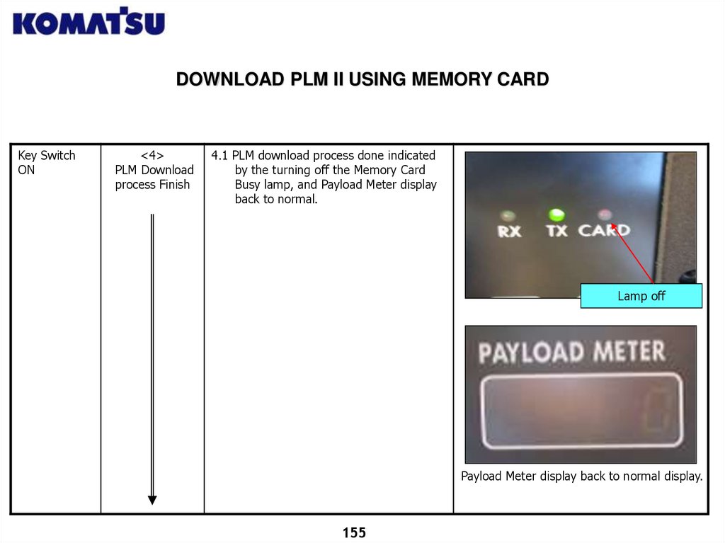
4.1 PLM download process done indicated
by the turning off the Memory Card
Busy lamp, and Payload Meter display
back to normal.
Lamp off
Payload Meter display back to normal display.
155
156.
DOWNLOAD PLM II USING MEMORY CARDKey Switch
OFF
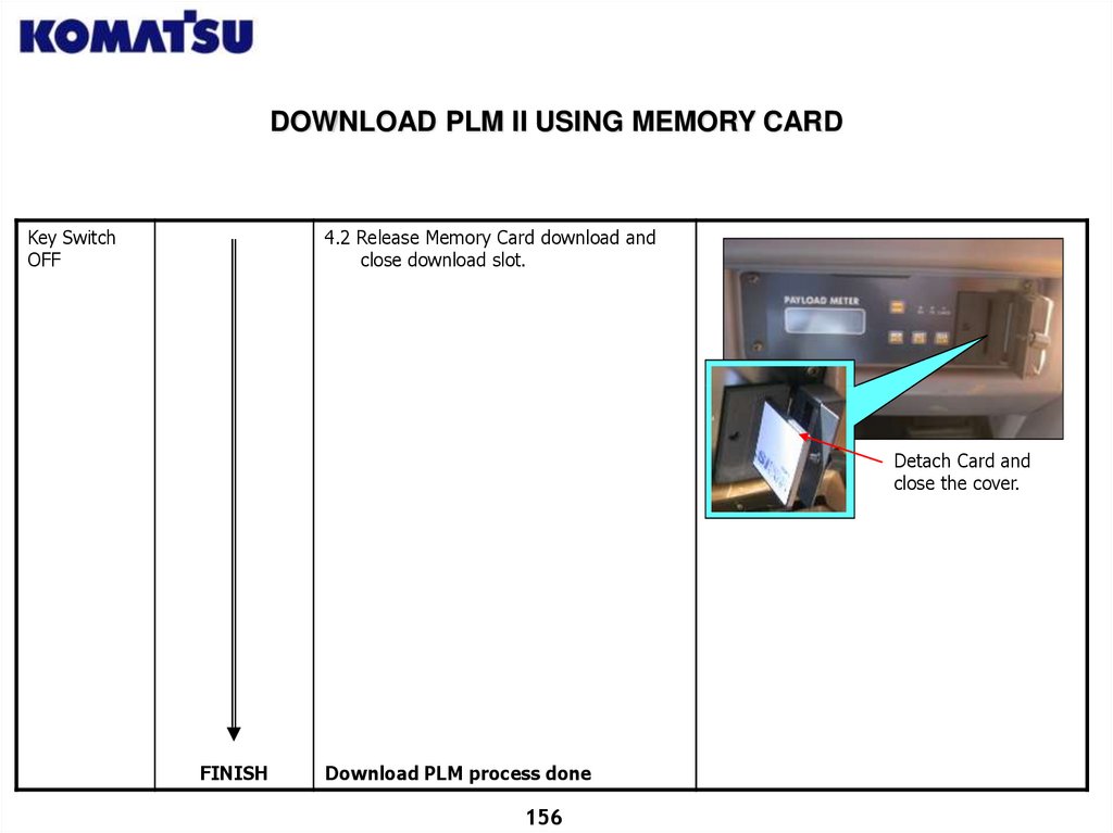
4.2 Release Memory Card download and
close download slot.
Detach Card and
close the cover.
FINISH
Download PLM process done
156
157.
DOWNLOADING PLM DATA FROM MEMORY CARD TO LAPTOP/DESKTOPUSING CARD READER
Download PLM from Memory Card definition:
A process to copy data from LSI KOMATSU Memory Card into
Laptop or Desktop using KOMATSU Card Reader tools.
General Purpose :
To get machine operation and production data.
Data copied is maximum load data per cycle, maximum speed per
cycle, etc which connected with production.
Note :
LSI Komatsu Memory Card capacity is only 128 kb, so one Memory
Card is only effective for only one unit.
KOMATSU Card Reader & KOMATSU LSI Memory Card (built in
lithium battery with expired date ) is a patent of KOMATSU .
This method is not applicable if PLM set to the unit is PLM I (printer
type) .
157
158.
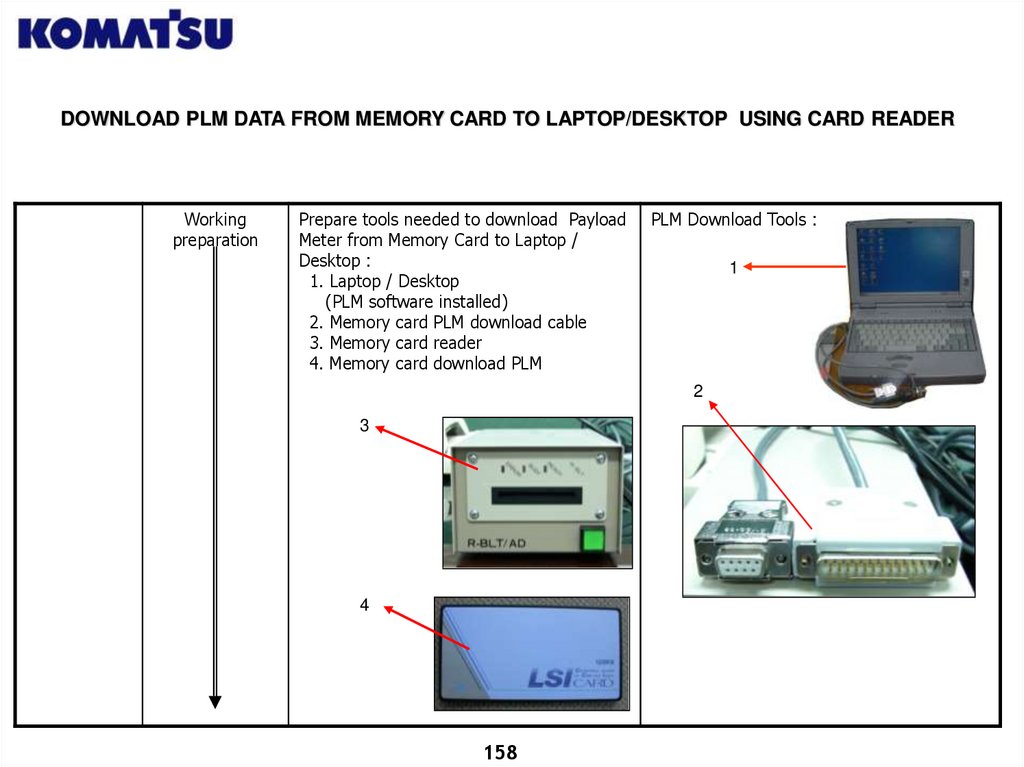
DOWNLOAD PLM DATA FROM MEMORY CARD TO LAPTOP/DESKTOP USING CARD READERWorking
preparation
Prepare tools needed to download Payload
Meter from Memory Card to Laptop /
Desktop :
1. Laptop / Desktop
(PLM software installed)
2. Memory card PLM download cable
3. Memory card reader
4. Memory card download PLM
PLM Download Tools :
1
2
3
4
158
159.
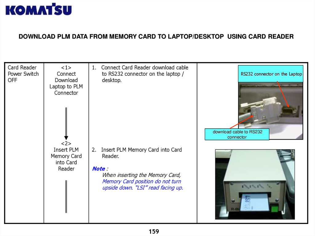
DOWNLOAD PLM DATA FROM MEMORY CARD TO LAPTOP/DESKTOP USING CARD READERCard Reader
Power Switch
OFF
<1>
Connect
Download
Laptop to PLM
Connector
1. Connect Card Reader download cable
to RS232 connector on the laptop /
desktop.
RS232 connector on the Laptop
download cable to RS232
connector
<2>
Insert PLM
Memory Card
into Card
Reader
2. Insert PLM Memory Card into Card
Reader.
Note :
When inserting the Memory Card,
Memory Card position do not turn
upside down. “LSI” read facing up.
159
160.
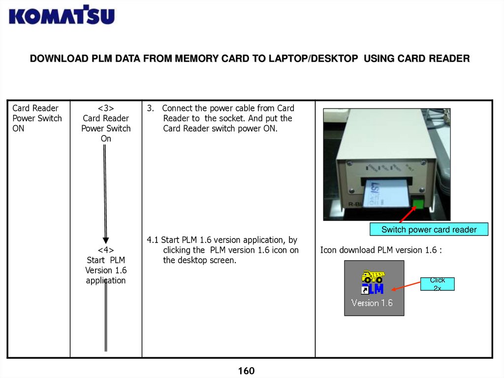
DOWNLOAD PLM DATA FROM MEMORY CARD TO LAPTOP/DESKTOP USING CARD READERCard Reader
Power Switch
ON
<3>
Card Reader
Power Switch
On
3. Connect the power cable from Card
Reader to the socket. And put the
Card Reader switch power ON.
Switch power card reader
<4>
Start PLM
Version 1.6
application
4.1 Start PLM 1.6 version application, by
clicking the PLM version 1.6 icon on
the desktop screen.
Icon download PLM version 1.6 :
Click
2x
160
161.
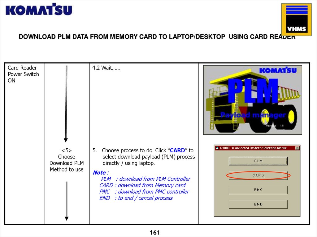
DOWNLOAD PLM DATA FROM MEMORY CARD TO LAPTOP/DESKTOP USING CARD READERCard Reader
Power Switch
ON
4.2 Wait……
<5>
Choose
Download PLM
Method to use
5. Choose process to do. Click “CARD” to
select download payload (PLM) process
directly / using laptop.
Note :
PLM
CARD
PMC
END
: download from PLM Controller
: download from Memory card
: download from PMC controller
: to end / cancel process
161
162.
DOWNLOAD PLM DATA FROM MEMORY CARD TO LAPTOP/DESKTOP USING CARD READERCard Reader
Power Switch
ON
<6>
Set Download
PLM Parameter
Setting
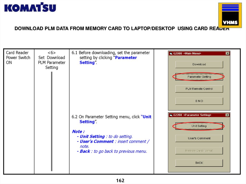
6.1 Before downloading, set the parameter
setting by clicking “Parameter
Setting”.
6.2 On Parameter Setting menu, click “Unit
Setting”.
Note :
- Unit Setting : to do setting.
- User’s Comment : insert comment /
note.
- Back : to go back to previous menu.
162
163.
DOWNLOAD PLM DATA FROM MEMORY CARD TO LAPTOP/DESKTOP USING CARD READERCard Reader
Power Switch
ON
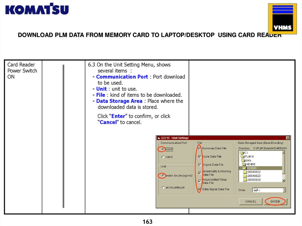
6.3 On the Unit Setting Menu, shows
several items :
- Communication Port : Port download
to be used.
- Unit : unit to use.
- File : kind of items to be downloaded.
- Data Storage Area : Place where the
downloaded data is stored.
Click “Enter” to confirm, or click
“Cancel” to cancel.
163
164.
DOWNLOAD PLM DATA FROM MEMORY CARD TO LAPTOP/DESKTOP USING CARD READERCard Reader
Power Switch
ON
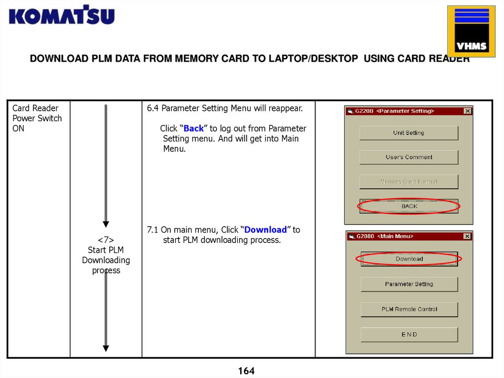
6.4 Parameter Setting Menu will reappear.
Click “Back” to log out from Parameter
Setting menu. And will get into Main
Menu.
<7>
Start PLM
Downloading
process
7.1 On main menu, Click “Download” to
start PLM downloading process.
164
165.
DOWNLOAD PLM DATA FROM MEMORY CARD TO LAPTOP/DESKTOP USING CARD READERCard Reader
Power Switch
ON
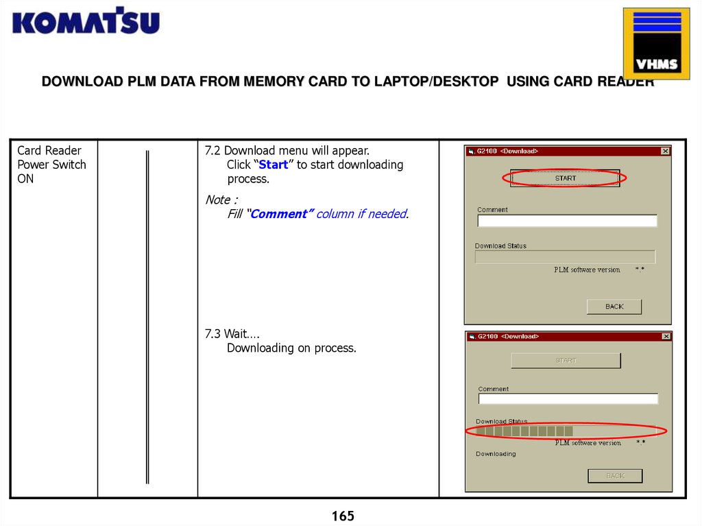
7.2 Download menu will appear.
Click “Start” to start downloading
process.
Note :
Fill “Comment” column if needed.
7.3 Wait….
Downloading on process.
165
166.
DOWNLOAD PLM DATA FROM MEMORY CARD TO LAPTOP/DESKTOP USING CARD READERCard Reader
Power Switch
ON
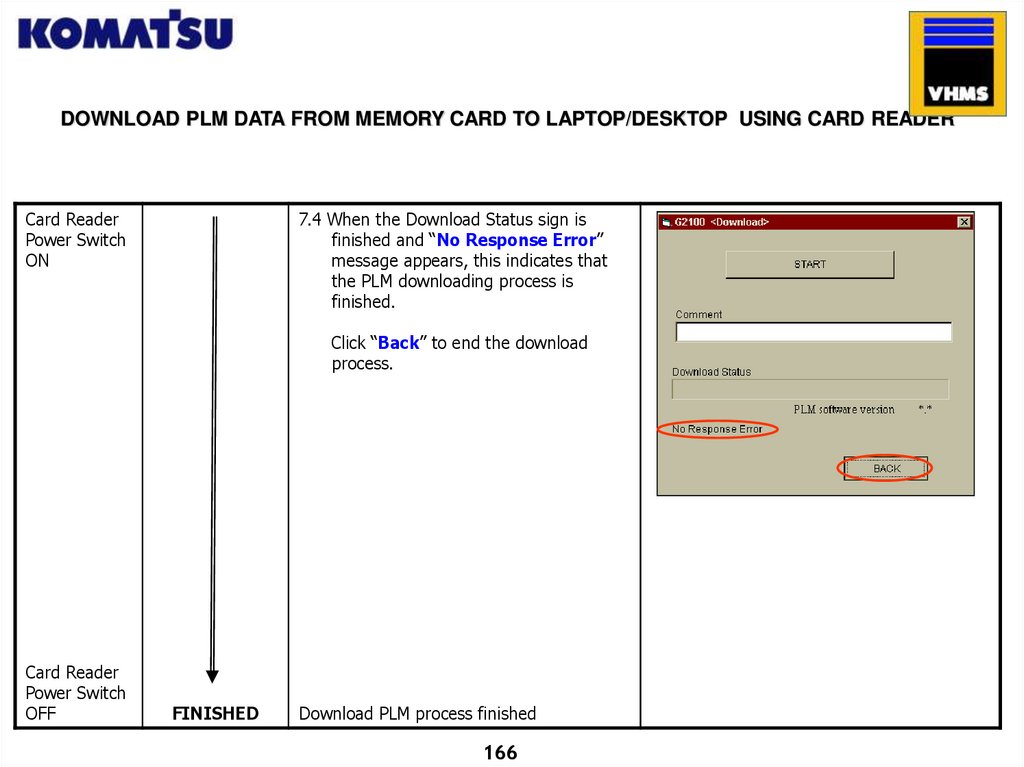
7.4 When the Download Status sign is
finished and “No Response Error”
message appears, this indicates that
the PLM downloading process is
finished.
Click “Back” to end the download
process.
Card Reader
Power Switch
OFF
FINISHED
Download PLM process finished
166
167.
POSTSCRIPTThis guidebook is originally prepared
by PT. United Tractors, Komatsu
distributor in Indonesia and reviewed
by PT. Komatsu Marketing & Support
Indonesia, in order to share our
experience of VHMS system among
Komatsu subsidiaries and distributors
in the world.
PT UNITED TRACTORS Tbk.
SERVICE DIVISION
This book describes in details the work
process starting from Down Load
process up to Technical Analysis
process.
With the launching of this book, it is
expected that every mechanic is able
to optimally utilize all benefits from
Pay Load Meter instrument & VHMS
Technology.
In line with the fast growing
technology reflected by Komatsu’s
newest products and Application
Improvement, we welcome inputs and
findings in the Continuous
Improvement and Mechanic’s
Competencies acceleration schemes.
PT. Komatsu Market & Support Indonesia
Thank you.
167
168.
END OF PAGE168