


 Маркетинг
Похожие презентации:
")
The CCK 11 MBps Modulation for IEEE 802.11 2.4 GHz WLANs
1. The CCK 11 MBps Modulation for IEEE 802.11 2.4 GHz WLANs
doc.: IEEE 802.11-98/315The CCK 11 MBps Modulation for
IEEE 802.11 2.4 GHz WLANs
Mark Webster and Carl Andren
Harris Semiconductor
With support from:
Jan Boer and Richard van Nee
Lucent Technologies
Submission
2. Summary
doc.: IEEE 802.11-98/315Summary
CCK modulation will enable 11 MBps operation in
the 2.4 GHz ISM band
•An interoperable preamble and a short preamble will
allow both interoperability and co-existence with
low rate LANs
Submission
3. Preamble Length
doc.: IEEE 802.11-98/315Our basic approach is to include the standard DS
or FH 802.11 preamble and header
•This length includes ample time to do diversity
and equalization
•For the cases where interoperability is not an
issue, a short, high rate header can be used.
•Antenna diversity, WEP initialization and
equalizer training require a somewhat longer
short preamble than the shortest possible.
Submission
4.
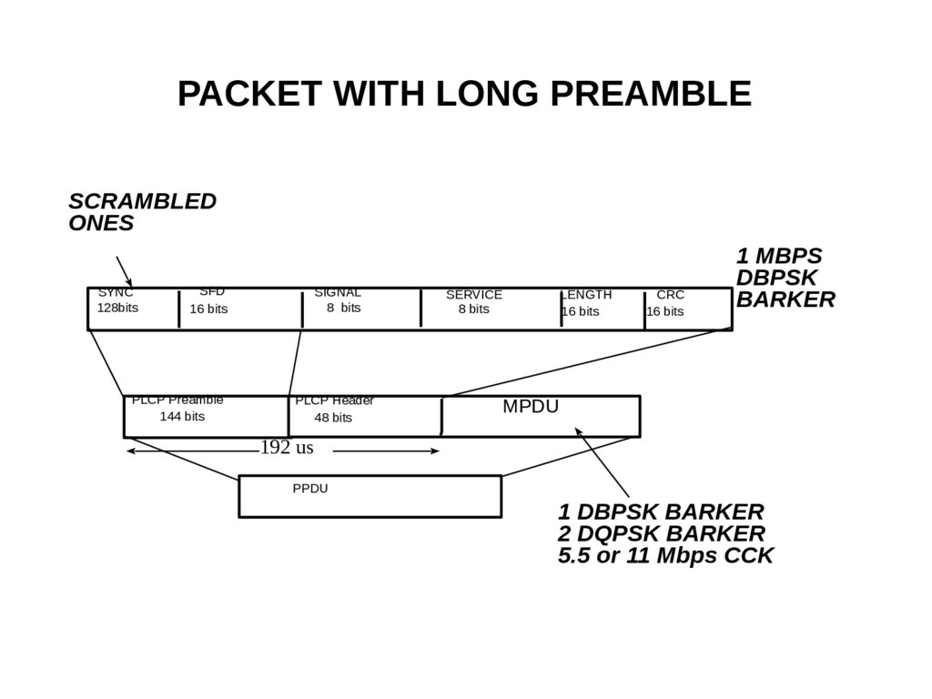
doc.: IEEE 802.11-98/315PACKET WITH LONG PREAMBLE
SCRAMBLED
ONES
SYNC
128bits
SFD
16 bits
PLCP Preamble
144 bits
SIGNAL
8 bits
PLCP Header
48 bits
SERVICE
8 bits
LENGTH
16 bits
CRC
16 bits
1 MBPS
DBPSK
BARKER
MPDU
192 us
PPDU
1 DBPSK BARKER
2 DQPSK BARKER
5.5 or 11 Mbps CCK
Submission
5.
doc.: IEEE 802.11-98/315PACKET WITH SHORT PREAMBLE
SCRAMBLED
ZEROS
shortSYNC
56 bits
BACKWARDS
SFD
shortSFD
16 bits
DBPSK BARKER
SIGNAL
8 bits
SERVICE
8 bits
LENGTH
16 bits
5.5 Mbps CCK
shortPLCP Preamble
72 bits @ 1 Mbit/s
PLCP Header
48 bits @ 5.5 Mbit/s
80.7 us
PPDU
Submission
MPDU
variable @ 5.5 or 11 Mbit/s
CRC
16 bits
6.
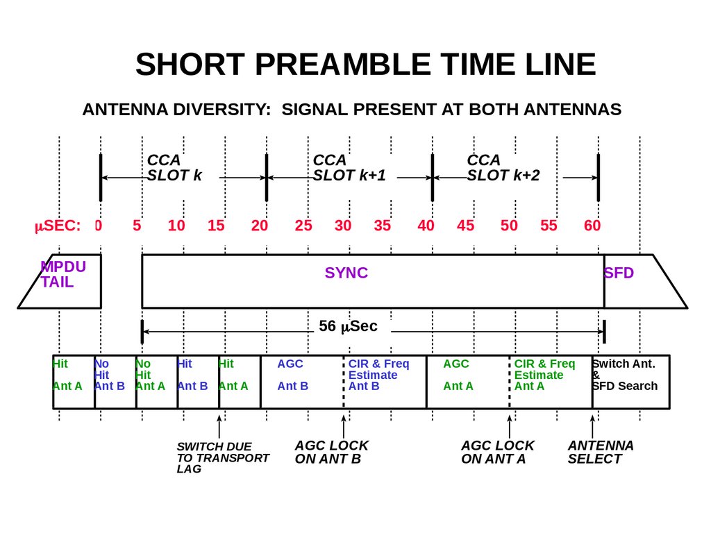
doc.: IEEE 802.11-98/315SHORT PREAMBLE TIME LINE
ANTENNA DIVERSITY: SIGNAL PRESENT AT BOTH ANTENNAS
CCA
SLOT k
mSEC: 0
5
10
CCA
SLOT k+1
15
20
25
MPDU
TAIL
30
35
CCA
SLOT k+2
40
45
50
55
60
SYNC
SFD
56 mSec
Hit
No
No
Hit
Hit
Hit
Hit
Ant A Ant B Ant A Ant B Ant A
SWITCH DUE
TO TRANSPORT
LAG
Submission
AGC
Ant B
CIR & Freq
Estimate
Ant B
AGC LOCK
ON ANT B
AGC
Ant A
CIR & Freq
Estimate
Ant A
AGC LOCK
ON ANT A
Switch Ant.
&
SFD Search
ANTENNA
SELECT
7.
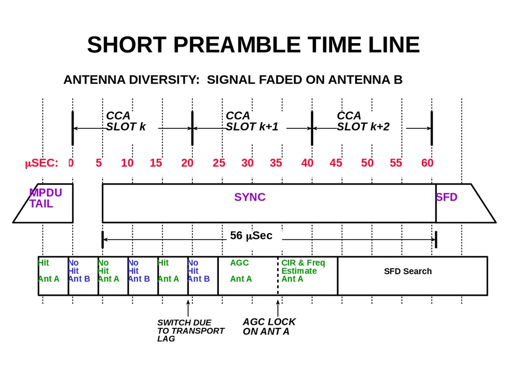
doc.: IEEE 802.11-98/315SHORT PREAMBLE TIME LINE
ANTENNA DIVERSITY: SIGNAL FADED ON ANTENNA B
CCA
SLOT k
mSEC: 0
5
10
CCA
SLOT k+1
15
20
25
MPDU
TAIL
30
CCA
SLOT k+2
35
40
45
50
55
60
SYNC
SFD
56 mSec
Hit
No
No
No
Hit
No
Hit
Hit
Hit
Hit
Ant A Ant B Ant A Ant B Ant A Ant B
SWITCH DUE
TO TRANSPORT
LAG
Submission
AGC
Ant A
CIR & Freq
Estimate
Ant A
AGC LOCK
ON ANT A
SFD Search
8.
doc.: IEEE 802.11-98/315SHORT PREAMBLE PERFORMANCE
JAM CIR ESTIMATE
AND FREQ OFFSET
AGC
LOCK
AGC
SIMULATION
PREAMBLE
SIMULATION
SYNC
10 mSec
SIMULATION PARAMETERS
FREQ OFFSET: 50 PPM
STATE: Linear (AGC locked)
TIME SPAN: 10 msec of Sync
SAMPLE RATE: 2 per Chip
CIR ESTIMATES: 11 Chip
CMF: Used CIR estimate
Submission
SYNC
PACKET-ERROR-RATE
SIMULATION
MPDU
10 mSec
64 BYTE PACKETS (Equalized RAKE)
DELAY SPREAD @ 10% PER:
350 nsec
Eb/No @ 20% PER with 350 nsec: 15.5 dB
9.
doc.: IEEE 802.11-98/315Throughput Comparison
Acknowledged Packets
10.00
9.00
8.00
7.00
Short Preamble
Long Preamble
5.00
2 Mbps
4.00
3.00
2.00
1.00
Bytes/Packet
Submission
1600
1536
1472
1408
1344
1280
1216
1152
1088
1024
960
896
832
768
704
640
576
512
448
384
320
256
192
128
0.00
64
Mbps
6.00
10. FH Interoperability Preamble
doc.: IEEE 802.11-98/315FH Interoperability Preamble
FH SYNC
80 bits
FH SFD
16 bits
FH PLCP Preamble
96 bits
PLW
12 bits
Short PLCP
FH PLCP Header
32 bits
120 BITS
GAP
128 us
PPDU
Submission
PSF
4 bits
CRC
16 bits
MPDU
11. Signal Field
doc.: IEEE 802.11-98/315Signal Field
The 8 bit 802.11 Signal Field indicates to the PHY the modulation which
shall be used for transmission (and reception) of the MPDU. The data
rate shall be equal to the Signal Field value multiplied by 100kbit/s.
The extended DSSS PHY supports four mandatory modulation services
given by the following 8 bit words, where the LSB shall be transmitted
first in time:
0Ah
– 14h
– 37h
– 6Eh
–
Submission
(MSB to LSB) for 1 Mbit/s DBPSK
(MSB to LSB) for 2 Mbit/s DQPSK
(MSB to LSB) for 5.5 Mbit/s CCK
(MSB to LSB) for 11 Mbit/s CCK
12. Length Field
doc.: IEEE 802.11-98/315Length Field
Since there is an ambiguity in the number of octets that will be described by a length in
microseconds for any data rate over 8 Mbit/s, an extra bit will be placed in the service
field to indicate when the smaller potential number is correct.
5.5Mbit/s CCK
Length = #octets * 8/5.5, rounded up to the next integer.
11Mbit/s CCK
Length = #octets * 8/11 , rounded up to the next integer and the service
field LSB bit shall indicate a ‘0’ if the rounding took less than 8/11 or a ‘1’ if the
rounding took more than 8/11.
At the receiver, the number of octets in the MPDU is calculated as follows:
5.5Mbit/s CCK
#octets = Length * 5.5/8, rounded down to the next integer
11Mbit/s CCK
#octets = Length * 11/8 , rounded down to the next integer, minus 1 if
the service field LSB bit is a ‘1’.
Submission
13. FH PSF Field
doc.: IEEE 802.11-98/315FH PSF Field
The first bit (#0) of the PSF which is reserved in clause 14.3.2.2.2 will be used to indicate that a high rate transmission will
follow. This bit is nominally 0 for transmissions compliant to the clause 14 standards. When raised to a 1, it will signal that
a high rate short preamble will follow. The remainder of the bits will indicate the rate which should be used to calculate the
end of the packet. Table shows the rate mapping of the PSF bits.
b0
b1
b2
b3
Indicated rate
0
X
X
X
Rates 1 - 4.5 Mbps per existing text
1
0
0
0
5.5 Mbps
1
0
0
1
11 Mbps
1
0
1
0
16.5 Mbps
1
0
1
1
22 Mbps
1
1
0
0
27.5 Mbps
1
1
0
1
33 Mbps
1
1
1
0
38.5 Mbps
1
1
1
1
44 Mbps
Submission
14. Modulation Technique and Data rates
doc.: IEEE 802.11-98/315c {e j ( 1 2 3 4 ) , e j ( 1 3 4 ) , e j ( 1 2 4 ) ,
11 Bit Barker Word
802.11 DSSS BPSK
1 MBps
Barker
BPSK
22 MHz
Code set
802.11 DSSS QPSK
2MBps
Barker
QPSK
1 bit used to
BPSK code word
I, Q
e j ( 1 4 ) , e j ( 1 2 3 ) , e j ( 1 3 ) , e j ( 1 2 ) , e j 1 }
6 bits encoded to
64 complex code
words; 2-QPSK
2 bits encoded to
4 complex code
words; 2-QPSK
2 bits used to
QPSK code word
I, Q
11 MBps
CCK
5.5 MBps
CCK
I, Q
I, Q
11 chips
11 chips
8 chips
8 chips
1 MSps
1 MSps
1.375 MSps
1.375 MSps
Submission
15. CODE DIMENSIONALITY
doc.: IEEE 802.11-98/315CODE DIMENSIONALITY
8 QPSK CHIPS: 4^8 = 65536 CCK Code words
64 CCK Code words are selected for maximum
distance properties with 4 rotations
Submission
16.
doc.: IEEE 802.11-98/315DIFFERENTIAL-PHASE MODULATION
Code word
Select Bits
DifferentialPhase Bits
CODE WORD
TABLE
Code word
PHASE
MAP
Quadri-phase
rotate
Previous-phase
Like 1 and 2 Mbps
• Noncoherent Rcvr
Enabled
Submission
Code words
17. Data Encoding 5.5 MBps
doc.: IEEE 802.11-98/315Data Encoding 5.5 MBps
Input data is broken into 4 bit nibbles where the first two bits are the sign bits d0 and
d1. These are encoded as differential carrier phase shift according to the table used for
2 MBps.
The next two bits of the nibble are encoded as CCK with d2 and d3 selecting the
symbol to be transmitted from the following table. Note that this table has the cover
code included. To get the raw symbol, negate the 4th and 7th chips.
d2, d3
00
:
1j
1
1j
1
1j
1
1j
1
01
:
1j
1
1j
1
1j
1
1j
1
10
:
1j
1
1j
1
1j
1
1j
1
11
:
1j
1
1j
1
1j
1
1j
1
The spread symbols are sent with the leftmost chip first in time. Notice that the chip
which is constant in phase across all symbols of the set is the last chip and this one
could be considered the symbol’s reference phase chip. The symbol’s cover code is
applied as the symbol leaves the modulator. The cover code rotates the chips.
Submission
18. Chip Encoding @ 5.5 MBps
doc.: IEEE 802.11-98/315Chip Encoding @ 5.5 MBps
Real/Imaginary form
from definition
I/Q form for modulation
+j
01
00
11
-1
10
11
-j
-Q
Q,I pairs
Complementary Codes (with cover)
00
:
1j
1
1j
1
1j
1
1j
1
01
:
1j
1
1j
1
1j
1
1j
1
10
:
1j
1
1j
1
1j
1
1j
1
11
:
1j
1
1j
1
1j
1
1j
1
Submission
+I
-I
+1
Rotate +45 degrees
(CCW) and convert
binary to Grey code
-j
Data
+1
00
01
10
-1
+Q
+j
01
10
10
01
00
11
11
11
01
10
10
01
11
00
11
00
01
01
10
10
00
00
00
00
10
10
01
01
00
00
00
00
19. Differential Encoding
doc.: IEEE 802.11-98/315Differential Encoding
Dibit pattern (d(0),d(1))
d(0) is first in time
00
01
11
10
Even Symbols
Phase Change (+j w )
0
p/2
p
3p/2 (-p/2)
Odd Symbols
Phase Change (+j w)
p
3p/2 (-p/2)
0
p/2
The differential phase encoding table treats odd and even
symbols differently.
Submission
20. CCK Modulator Technique for 5.5 MBps
doc.: IEEE 802.11-98/315CCK Modulator Technique for 5.5
MBps
d2, d3
Pick One of
4 Complex
Codes *
Complex
Multiply,
Rotate
Complex
Multiply,
Rotate
I OUT
Q OUT
DATA
IN
Scrambler
MUX
1:4
d0
Differentially
Encode Phases,
Odd/Even
d1
Cover Codes
1.375 MHz
11 MHz
11 MHz
Data Rate = 4 bits/symbol * 1.375 MSps = 5.5 MBps
Submission
21. CCK Cover Sequences
doc.: IEEE 802.11-98/315CCK Cover Sequences
The only cover sequence so far defined is one
that rotates the 4th and 7th chips by 180
degrees.
•This makes the DC term of the data #0h
symbol less of a problem
•In general other cover sequences may rotate
any chip into any quadrant, so a 16 bit
sequence is needed to define them.
Submission
22. CCK Cover Code Rotations
doc.: IEEE 802.11-98/315CCK Cover Code Rotations
The data and cover code are
performed in the I/Q domain and
the output is also in this domain.
All operations are in Grey code
• The cover code application and
removal requires a rotational
decode, so the best approach is a
look up table .
+Q
01
00
-I
+I
11
10
-Q
Submission
data, rotation
00
00
00
00
01
01
01
01
11
11
11
11
10
10
10
10
00
01
11
10
00
01
11
10
00
01
11
10
00
01
11
10
output
00
01
11
10
01
11
10
00
11
10
00
01
10
00
01
11
23. Data Demodulation, 5.5 MBps
doc.: IEEE 802.11-98/315Data Demodulation, 5.5 MBps
Analog
Input
Select 5.5 set
A/D converter
CCK Data Mapping
Compl.
Mult
Decover
rotation
Fast
Walsh
Transform
Biggest
Picker
Sign
Detector
2
Carrier
PLL
Submission
Cover
Sequence
Data
Reformatter,
serializer
Binary to
Grey and
Differential
Detector
2
Descrambler
Data
Output
24. CCK Data Mapping
doc.: IEEE 802.11-98/315CCK Data Mapping
Binary to Grey and Differential Decoding
The first output data bit of the Biggest Picker and sign
detector represents a 180 degree change and the second
bit a 90 degree change. This is a binary code
• The mapping from the raw data to the output bits works
out as binary to Grey decoding.
• Additionally, the differential decoding requires a odd/even
rotational decode, so the best approach is a look up
table which does all at once.
Submission
25. Data Encoding 11 MBps
doc.: IEEE 802.11-98/315Data Encoding 11 MBps
Input data is broken into bytes where the first two bits are the phase bits d0
and d1. These are differentially encoded as carrier phase shift according to
the table on following slide. The next six bits of the byte are encoded as CCK
with d2 to d7 selecting the symbol to be transmitted from the following
formula:
j( 1 2 3 4) j( 1 3 4) j( 1 2 4)
c {e
,e
,e
,
j( 1 4) j( 1 2 3) j( 1 3)
e
,e
,e
,
j( 1 2) j 1
e
,e }
The f1 term is the phase term derived from d0 and d1 according to the
table on the following slide. The f2 term is derived from the d2, d3 pair,
f3 from the d4, d5 pair, and f4 from the d6, d7 pair, all in accordance with
the chart on the following slide. A look up table will most likely be the
form of the symbol encoding for the d2..d7 terms.
Submission
26. Encoding 11 MBps Continued
doc.: IEEE 802.11-98/315Encoding 11 MBps Continued
The table below shows how the d0..d7 terms are pairwise encoded into the
phase terms.
Dibit pattern (d(i),d(i+1))
d(i) is first in time
00
01
11
10
Phase
0
+1
+j
p/2
p
1
3p/2 (-p/2)
-j
The spread symbols are sent with the left most chip first in time. Notice that
the chip which carries the symbol’s phase is the last chip.
The symbol cover code is applied after the symbol has been defined.
Submission
27. CCK Modulator Technique for 11 MBps Modulation
doc.: IEEE 802.11-98/315CCK Modulator Technique for 11
MBps Modulation
d2…d7
Pick One of
64 Complex
Codes
Complex
Multiply,
Rotate
Complex
Multiply,
Rotate
I OUT
Q OUT
DATA
IN
Scrambler
MUX
1:8
d0
Differentially
Encode Phases,
odd/even
d1
Cover Code
1.375 MHz
11 MHz
11 MHz
Data Rate = 8 bits/symbol * 1.375 MSps = 11 MBps
Submission
28. Data Demodulation, 11 MBps
doc.: IEEE 802.11-98/315Data Demodulation, 11 MBps
Analog
Input
Select 11
A/D converter
Compl.
Mult
Decover
Fast
Walsh
Transform
Biggest
Picker
Sign
Detector
6
Carrier
PLL
Submission
Cover
Sequence
Data
Reformatter
Binary to
Grey and
Differential
Detector
2
Descrambler
Data
Output
29. Adjacent channel interference
doc.: IEEE 802.11-98/315Adjacent channel interference
ACI @ 25 MHz separation: 30 - 35dB
makes a 3 frequency channel topology possible at
certain distance mix
– 3 X throughput
–
x
3m
60m
Submission
3m
x
3m
x
30. Receiver Minimum Input Level Sensitivity
doc.: IEEE 802.11-98/315Receiver Minimum Input Level
Sensitivity
The Frame Error Rate (FER) shall be less than 8x10⁻²
at an MPDU length of 1024 octets for an input
level of -80 dBm measured at the antenna
connector. This FER shall be specified for 11
Mbit/s CCK modulation. The test for the
minimum input level sensitivity shall be conducted
with the energy detection threshold set less than or
equal to -80 dBm.
Submission
31. CCA mechanism and Co-Channel signal detection time
doc.: IEEE 802.11-98/315CCA mechanism and
Co-Channel signal detection time
We measure the correlated signal energy in the
preamble over 5 us dwells beginning when the
receiver is enabled and compare that to a threshold
•The detection time is less than the slot time by
enough to include diversity
•FH detection is done on clock energy in similar
dwells.
Submission
32. CCA
doc.: IEEE 802.11-98/315CCA
The DSSS PHY shall provide the capability to perform Clear Channel
Assessment (CCA) according to at least one of the following three
methods:
CCA Mode 1: Energy above threshold. CCA shall report a busy
medium upon detecting any energy above the ED threshold.
– CCA Mode 2: Carrier or modulation sense only. CCA shall report a
busy medium only upon the detection of a DSSS signal. This
signal may be above or below the ED threshold.
– CCA Mode 3: Carrier or modulation sense with energy above
threshold. CCA shall report a busy medium upon the detection of a
DSSS signal with energy above the ED threshold.
–
Submission
33. CCA Threshold
doc.: IEEE 802.11-98/315CCA Threshold
The CCK codes are not as easily detected as Barker Codes, so detection may not
occur in the middle of the message. This is a rare event except when a packet
is dropped in the middle, for example when a receiver not configured for the
optional short preamble sees one.
a). If the valid signal is detected during its preamble within the CCA
assessment window, the energy detection threshold for 98 % probability of
detection shall be less than or equal to
– -80 dBm for TX power > 100 mW
–
-76 dBm for 50 mW < TX power <= 100 mW
• -70 dBm for TX power <= 50 mW.
After detection of the carrier in the short preamble by a receiver not capable of
processing the short preamble, CCA busy is raised. When no SFD is detected
CCA shall be kept busy until an energy drop of 10 dB. Thus, during the whole
message (which is known to be a 802.11 message but not understood by the
receiver) the receiving modem will keep silent. After the energy drop the
modem will be in slot sync again.
Submission
34. Interoperability
doc.: IEEE 802.11-98/315Interoperability
CCK can recognize both long and short preambles. If the CCK receiver detects a short
preamble it trains on the short. If the receiver detects the long preamble it trains on the
long preamble. If long, it can now also recognize the data rate, which can be a legacy
DSSS rate (1 or 2 Mbit/s).
Scenario: CCK starts with a short preamble. Legacy DSSSS modems defer on that preamble.
It is normally received by the CCK modems that have the option to receive a short
preamble. The CCK modem can receive both CCK (short and long) and legacy DSSS
transmissions. If reception is poor (or there is, for whatever reason, a coexistence problem
with IEEE modems), the transmitter falls back to 5.5 Mbit/s or to the long preamble. The
long preamble is also recognized by the legacy DSSS only modems, making use of the
IEEE imbedded multi-rate capability.
Result: CCK modems send, if circumstances allow, the short preamble, making full use of the
higher throughput capabilities. They are at all times interoperable with legacy DSSS
modems, recognizing the long preamble, receiving (and sending) at the low rates. If there
are coexistence problems the CCK modems falls back to the long preamble.
Submission
35. Coexistence
doc.: IEEE 802.11-98/315Coexistence
Low rate and high rate PHYs will coexist within the same network.
• Short preambles will be used only within networks of high rate PHYs
• Short and long preambles may be intermingled on the same network.
• All (rate) PHYs will perform CCA on either long or short preambles
• Performing CCA in the middle of a packet on CCK is problematic.
Submission
36. Coexistence Philosophy
doc.: IEEE 802.11-98/315Coexistence Philosophy
Coexistence means that short preamble CCK defers for legacy
DSSS (and long CCK) and vice versa.
• legacy DSSS
detects short preamble (carrier or energy); CCA reports channel busy;
– waits for Start frame delimiter but will not find it.
– It is not prescribed in the standard what action the receiver has to take, there are several
possibilities:
– once the CCK signal starts after the preamble, the receiver might loose code lock and causes CCA
to go to the channel IDLE state. The receiver returns to the RX idle state and starts looking for a
carrier, which it does not see (because of CCK). This might result in a collision or the receiver
being out of slot sync.
– The receiver times out on the SFD. This also leads to out of sync and possible collision
– CCA reports channel busy until the ED drop of the CCK signal. In this case the DSSS receiver stays
in slot sync.
– It is clear that the third implementation (ED) is the best guaranty for coexistence.
–
Submission
37. Coexistence Philosophy
doc.: IEEE 802.11-98/315Coexistence Philosophy
CCK receiver
configured to process a short preamble, the receiver will also detect the long
preamble and process the legacy DSSS frame. The CCK receiver can see
the legacy transmitter CS in the middle of a message and defer if
necessary.
– On the CCK portion of the packet, the CCK receiver also loses the CS if it is
based on Barker correlation and will not behave. Therefore it too needs a
better CCA measure like improved ED.
–
Submission