


 Физика
Похожие презентации:


")


Capacitors
1.
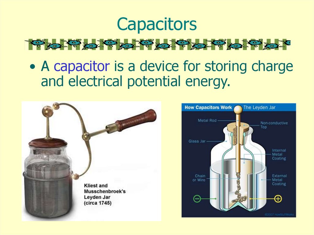
Capacitors• A capacitor is a device for storing charge
and electrical potential energy.
2.
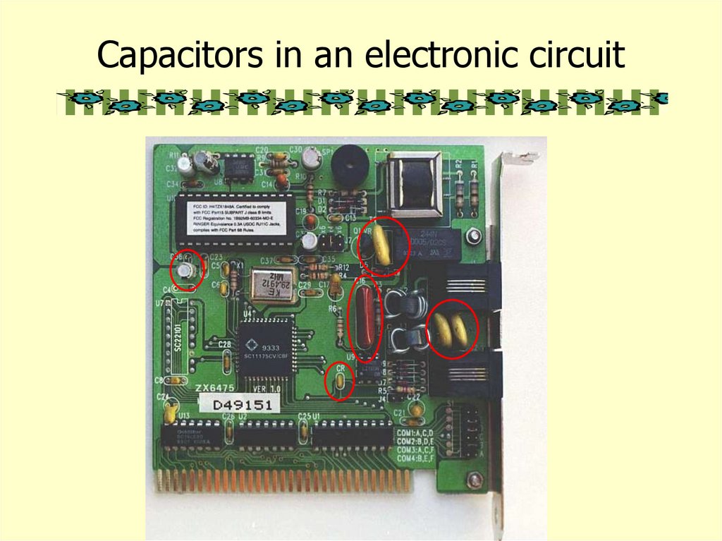
Capacitors in an electronic circuit3.
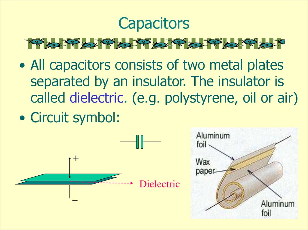
Capacitors• All capacitors consists of two metal plates
separated by an insulator. The insulator is
called dielectric. (e.g. polystyrene, oil or air)
• Circuit symbol:
+
Dielectric
_
4.
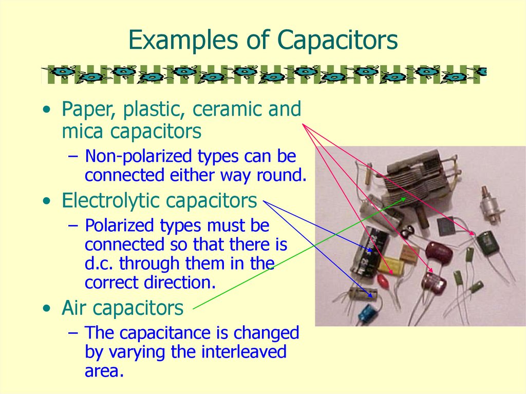
Examples of Capacitors• Paper, plastic, ceramic and
mica capacitors
– Non-polarized types can be
connected either way round.
• Electrolytic capacitors
– Polarized types must be
connected so that there is
d.c. through them in the
correct direction.
• Air capacitors
– The capacitance is changed
by varying the interleaved
area.
5.
Formation of a Capacitor• Capacitors are formed all
of the time in everyday
situations:
– when a charged
thunderstorm cloud
induces an opposite
charge in the ground
below,
– when you put your hand
near the monitor screen of
this computer.
http://micro.magnet.fsu.edu/electromag/java/lightning/index.html
6.
Charged Capacitor• A capacitor is said to be charged when
there are more electrons on one
conductor plate than on the other.
When a capacitor is
charged, energy is
stored in the
dielectric material in
the form of an
electrostatic field.
http://micro.magnet.fsu.edu/electromag/java/capacitor/index.html
7.
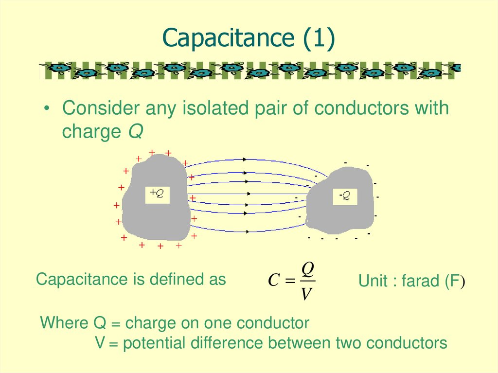
Capacitance (1)• Consider any isolated pair of conductors with
charge Q
Capacitance is defined as
Q
C
V
Unit : farad (F)
Where Q = charge on one conductor
V = potential difference between two conductors
8.
Capacitance (2)• The capacitance of a conductor is the charge
required to cause unit change in the potential of
the conductor.
A one-farad capacitor stores one coulomb of
charge when a potential of 1 volt is applied
across the terminals of the capacitor.
The smaller the change in potential of the
conductor when a certain charge is transferred
to it, the more charge it can store before
breakdown occurs.
In electronics, the microfarad (μF) and the
picofarad (pF) are usually used to measure
capacitance.
9.
Capacitance of a CapacitorQ
C
V
• Note that Q is not the net charge on the capacitor,
which is zero.
• Capacitance is a measure of a capacitor's ability
to store charge.
• The more charge a capacitor can hold at a given
potential difference, the larger is the capacitance.
• Capacitance is also a measure of the energy
storage capability of a capacitor.
10.
Voltage Rating of Capacitors• If the voltage applied across the
capacitor is too great, the
dielectric will break down and
arcing will occur between the
capacitor plates.
• The voltage rating of the
capacitor is the maximum
voltage that can be steadily
applied without danger of
breaking down the dielectric.
11.
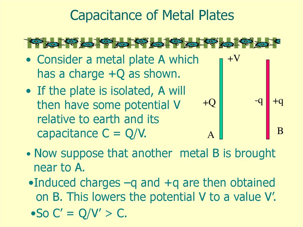
Capacitance of Metal Plates+V
• Consider a metal plate A which
has a charge +Q as shown.
• If the plate is isolated, A will
+Q
then have some potential V
relative to earth and its
capacitance C = Q/V.
A
-q +q
• Now suppose that another metal B is brought
near to A.
•Induced charges –q and +q are then obtained
on B. This lowers the potential V to a value V’.
•So C’ = Q/V’ > C.
B
12.
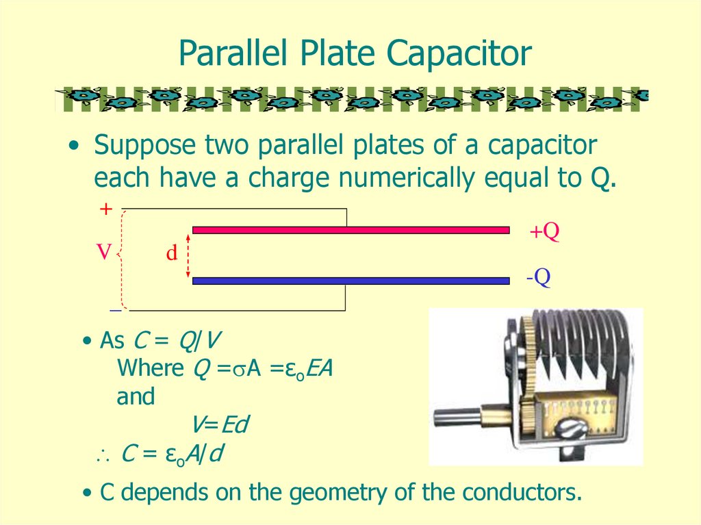
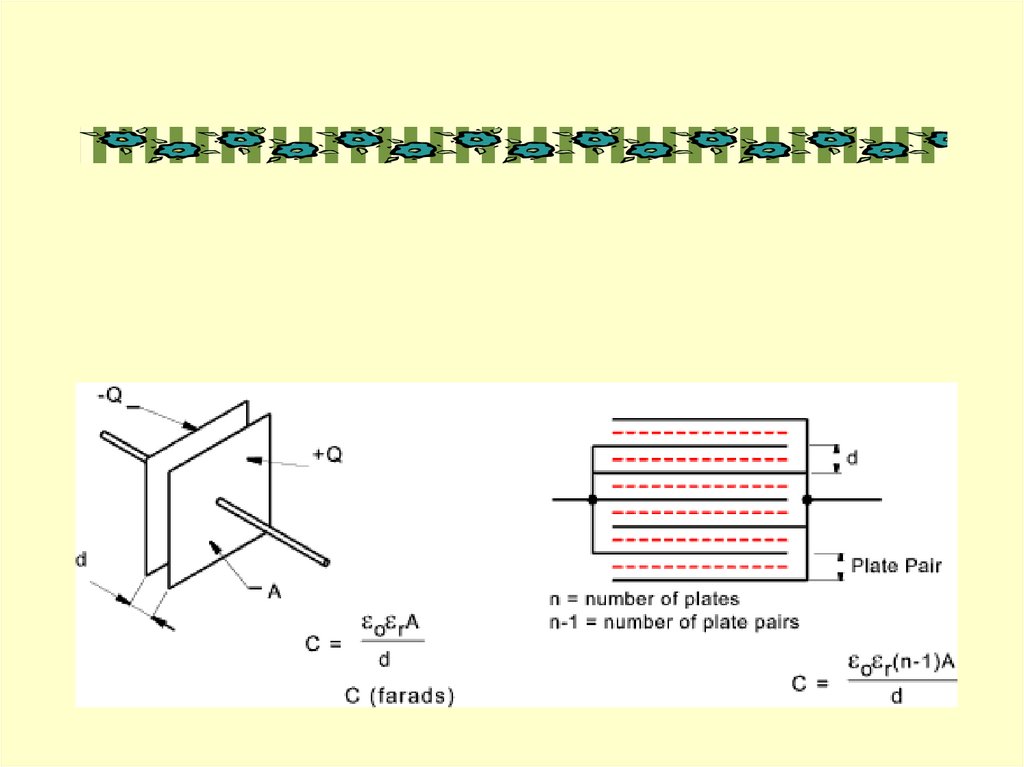
Parallel Plate Capacitor• Suppose two parallel plates of a capacitor
each have a charge numerically equal to Q.
+
+Q
V
d
-Q
_
• As C = Q/V
Where Q = A =εoEA
and
V=Ed
C = εoA/d
• C depends on the geometry of the conductors.
13.
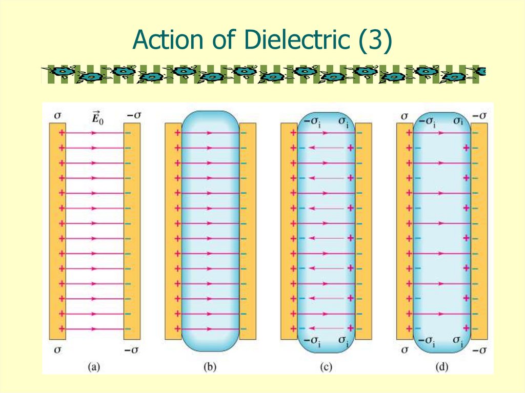
Action of Dielectric (1)• A molecule can be regarded as a collection of atomic
nuclei, positively charged, and surrounded by a cloud of
negative electrons.
- - + - no field
no net charge
net -ve
charge
- - +- -
net +ve
charge
Field
• When the molecule is in an electric field, the nuclei are
urged in the direction of the field, and the electrons in
the opposite direction.
• The molecule is said to be polarized.
14.
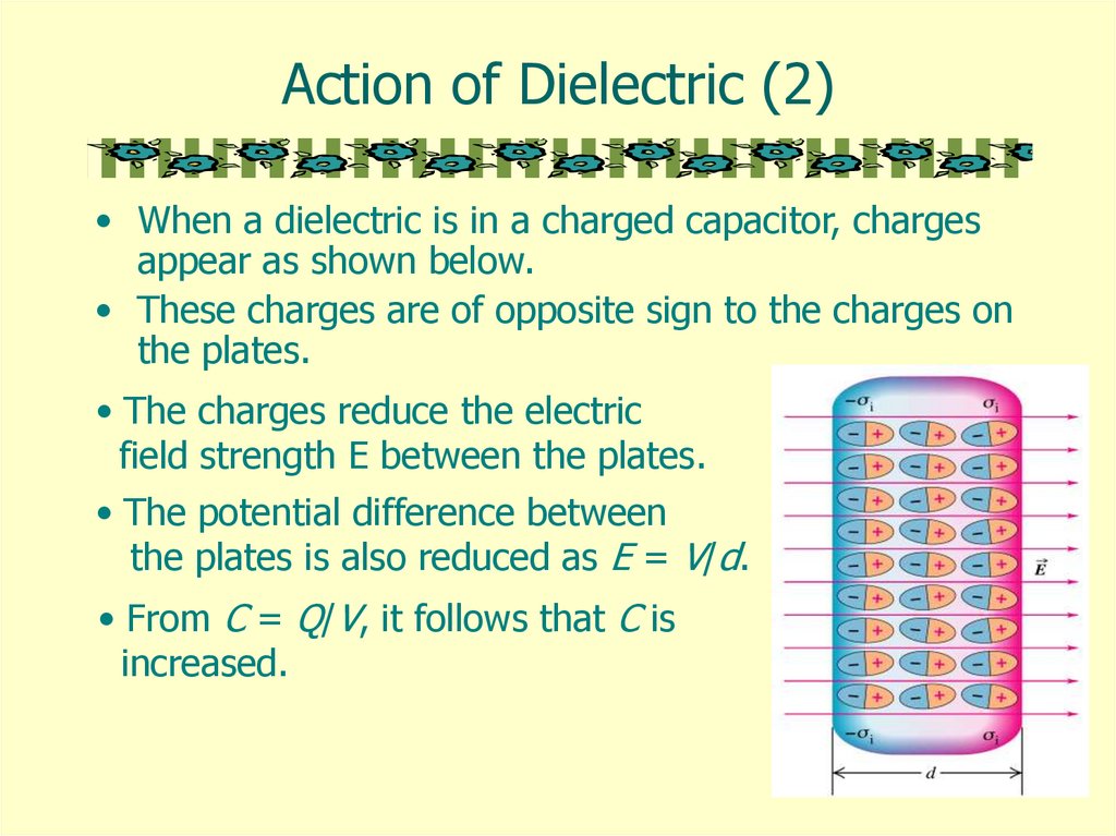
Action of Dielectric (2)• When a dielectric is in a charged capacitor, charges
appear as shown below.
• These charges are of opposite sign to the charges on
the plates.
• The charges reduce the electric
field strength E between the plates.
• The potential difference between
the plates is also reduced as E = V/d.
• From C = Q/V, it follows that C is
increased.
15.
Action of Dielectric (3)16.
Functions of Dielectrics• It solves the mechanical problem of
maintaining two large metal plates at a very
small separation without actual contact.
• Using a dielectric increases the maximum
possible potential difference between the
capacitor plates without allowing discharge.
• With the dielectric present, the p.d. for a
given charge Q is reduced by a factor εr and
hence the capacitance of the capacitor is
increased.
17.
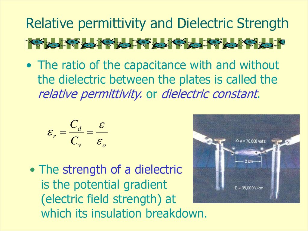
Relative permittivity and Dielectric Strength• The ratio of the capacitance with and without
the dielectric between the plates is called the
relative permittivity. or dielectric constant.
Cd
r
Cv o
• The strength of a dielectric
is the potential gradient
(electric field strength) at
which its insulation breakdown.
18.
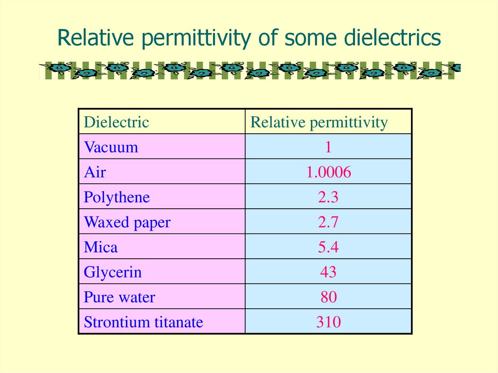
Relative permittivity of some dielectricsDielectric
Vacuum
Air
Polythene
Waxed paper
Relative permittivity
1
1.0006
2.3
2.7
Mica
Glycerin
Pure water
5.4
43
80
Strontium titanate
310
19.
Variable Capacitorhttp://micro.magnet.fsu.edu/electromag/java/varcapacitor/index.html
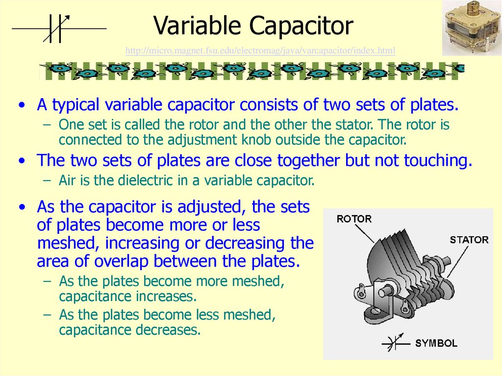
• A typical variable capacitor consists of two sets of plates.
– One set is called the rotor and the other the stator. The rotor is
connected to the adjustment knob outside the capacitor.
• The two sets of plates are close together but not touching.
– Air is the dielectric in a variable capacitor.
• As the capacitor is adjusted, the sets
of plates become more or less
meshed, increasing or decreasing the
area of overlap between the plates.
– As the plates become more meshed,
capacitance increases.
– As the plates become less meshed,
capacitance decreases.
20.
Combination of Capacitor (1)• In series
Q Q1 Q2 Q3
V V1 V2 V3
1
1
1
1
C C1 C2 C3
1 1 1
V1 : V2 : V3
:
:
C 1 C2 C3
The resultant capacitance is smaller than the smallest
Individual one.
21.
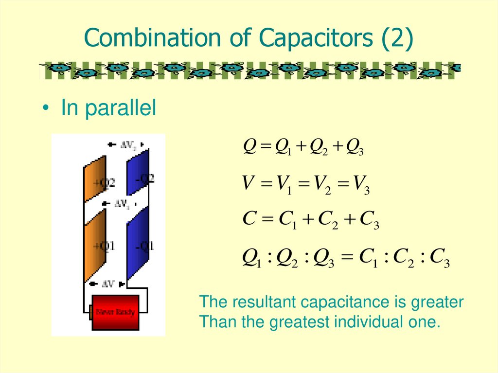
Combination of Capacitors (2)• In parallel
Q Q1 Q2 Q3
V V1 V2 V3
C C1 C2 C3
Q1 : Q2 : Q3 C1 : C2 : C3
The resultant capacitance is greater
Than the greatest individual one.
22.
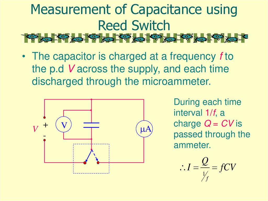
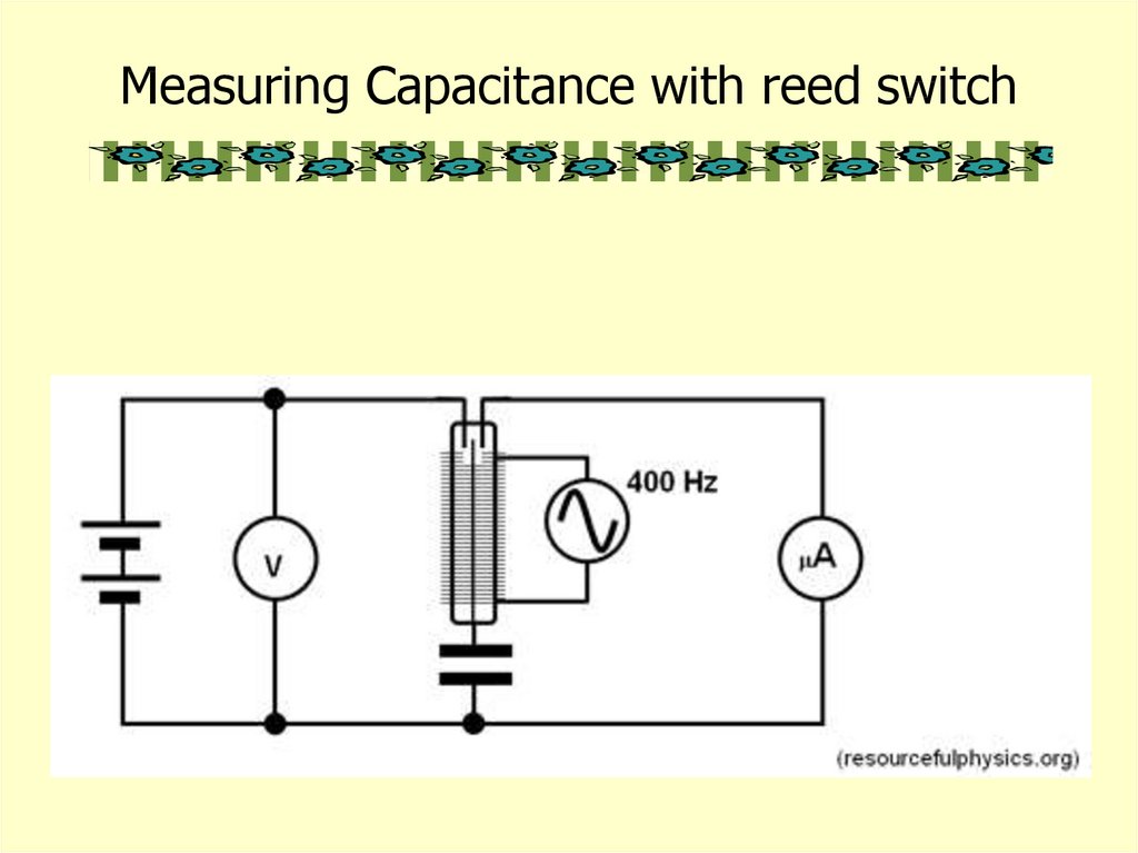
Measurement of Capacitance usingReed Switch
• The capacitor is charged at a frequency f to
the p.d V across the supply, and each time
discharged through the microammeter.
V +
-
V
A
During each time
interval 1/f, a
charge Q = CV is
passed through the
ammeter.
I
Q
1
f
fCV
23.
Measurement of Capacitance usingElectrometer
24.
Stray Capacitance• The increased capacitance due to nearby
objects is called the stray capacitance Cs which
is defined by
• C = Co + Cs
– Where C is the measured capacitance.
• Stray capacitance exists in all circuits to some
extent. While usually to ground, it can occur
between any two points with different potentials.
• Sometimes stray capacitance can be used to
advantage, usually you take it into account but
often it's a monumental pain.
25.
Measurement of Stray Capacitance• In measuring capacitance of a capacitor,
the stray capacitance can be found as
follows:
C
C
Cs
0
1/d
o A
d
Cs
26.
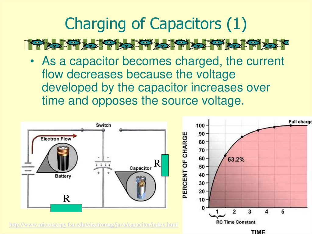
Charging of Capacitors (1)• As a capacitor becomes charged, the current
flow decreases because the voltage
developed by the capacitor increases over
time and opposes the source voltage.
R
R
http://www.microscopy.fsu.edu/electromag/java/capacitor/index.html
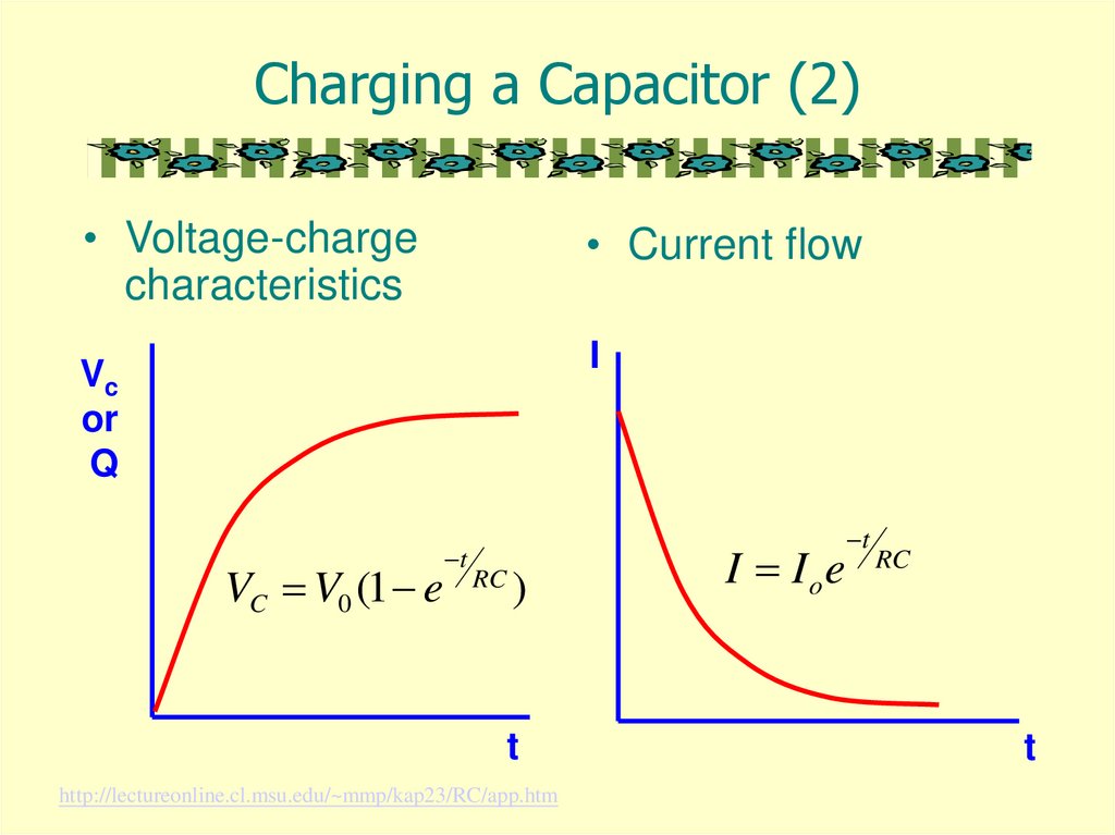
27.
Charging a Capacitor (2)• Voltage-charge
characteristics
• Current flow
I
Vc
or
Q
VC V0 (1 e
t
RC
)
t
http://lectureonline.cl.msu.edu/~mmp/kap23/RC/app.htm
I I oe
t
RC
t
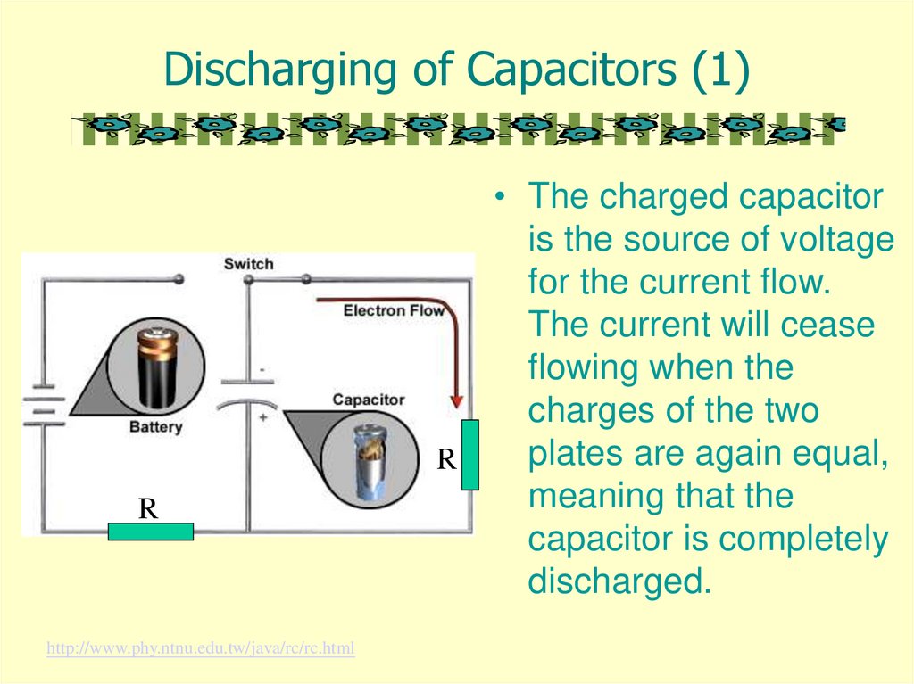
28.
Discharging of Capacitors (1)R
R
http://www.phy.ntnu.edu.tw/java/rc/rc.html
• The charged capacitor
is the source of voltage
for the current flow.
The current will cease
flowing when the
charges of the two
plates are again equal,
meaning that the
capacitor is completely
discharged.
29.
Discharging a Capacitor (2)• Voltage-charge
characteristics
• Current flow
t
VC
or
Q
Q Q0e
t
I I oe
RC
I
t
t
RC
30.
Time Constant ( )• = CR
• The time constant is used to measure how long
it takes to charge a capacitor through a resistor.
• The time constant may also be defined as the
time taken for the charge to decay to 1/e times
its initial value.
• The greater the value of CR, the more slowly
the charge is stored.
• Half-life
– The half-life is the time taken for the charge in a
capacitor to decay to half of its initial value.
– T1/2 = CR ln 2
31.
Energy Stored in a Charged Capacitorhttp://www.matter.org.uk/schools/Content/Capacitors/energy2.html
• The area under
the graph gives
the energy stored
in the capacitor.
Q
0
V
1
E QV
2
1
CV 2
2
1 Q2
2 C
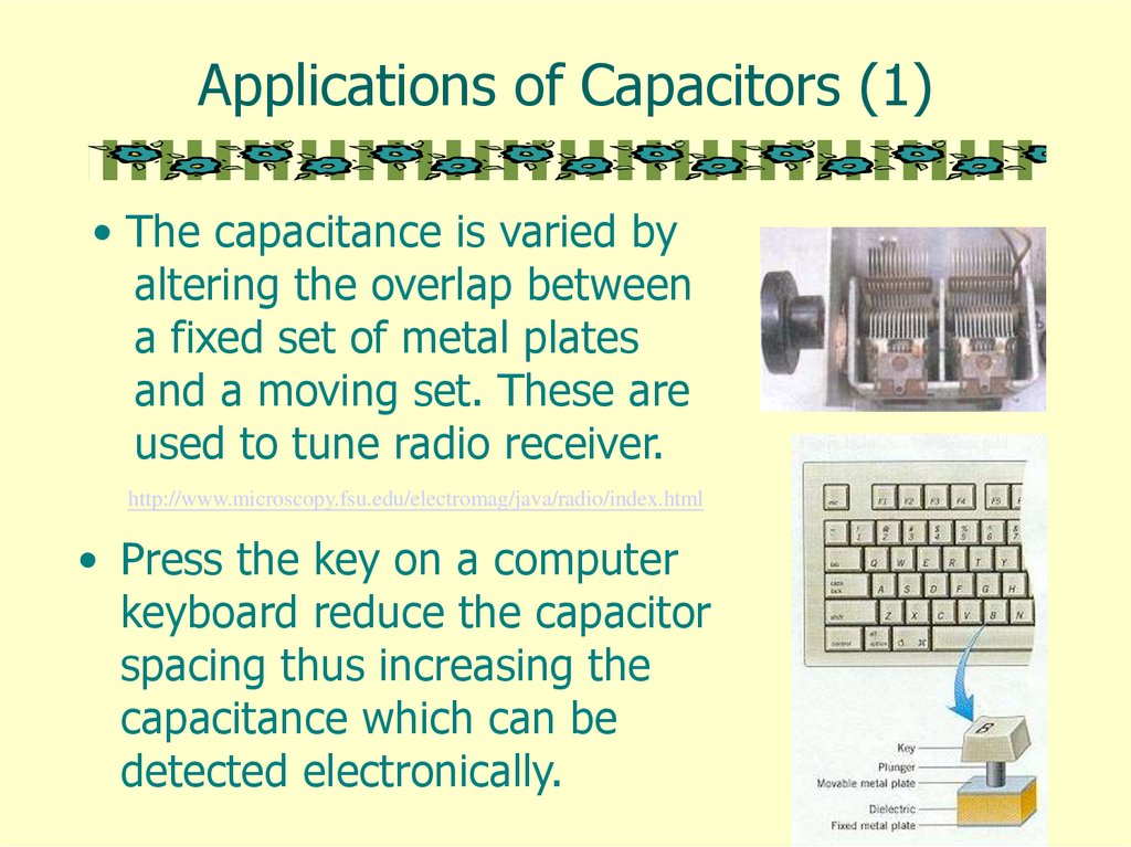
32.
Applications of Capacitors (1)• The capacitance is varied by
altering the overlap between
a fixed set of metal plates
and a moving set. These are
used to tune radio receiver.
http://www.microscopy.fsu.edu/electromag/java/radio/index.html
• Press the key on a computer
keyboard reduce the capacitor
spacing thus increasing the
capacitance which can be
detected electronically.
33.
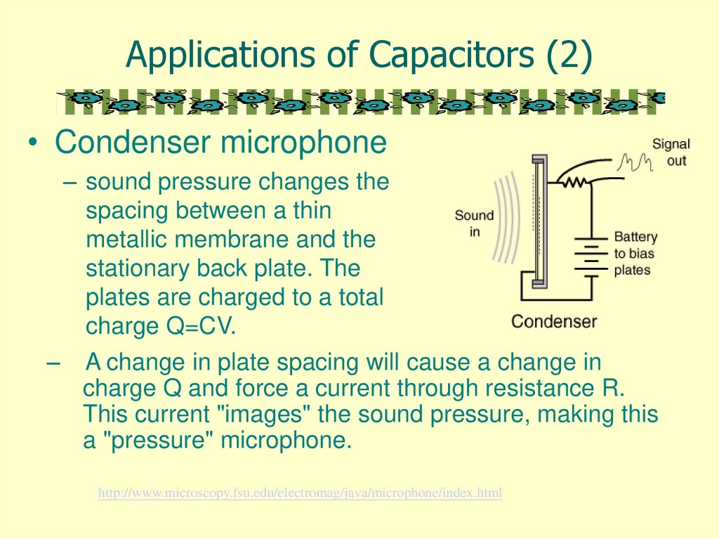
Applications of Capacitors (2)• Condenser microphone
– sound pressure changes the
spacing between a thin
metallic membrane and the
stationary back plate. The
plates are charged to a total
charge Q=CV.
–
A change in plate spacing will cause a change in
charge Q and force a current through resistance R.
This current "images" the sound pressure, making this
a "pressure" microphone.
http://www.microscopy.fsu.edu/electromag/java/microphone/index.html
34.
Applications of Capacitors (3)• Electronic flash on a camera
– The battery charges up the
flash’s capacitor over several
seconds, and then the capacitor
dumps the full charge into the
flash tube almost instantly.
– A high voltage pulse is generated
across the flash tube.
– The capacitor discharges
through gas in the the flash tube
and bright light is emitted.
http://electronics.howstuffworks.com/capacitor.htm
35.
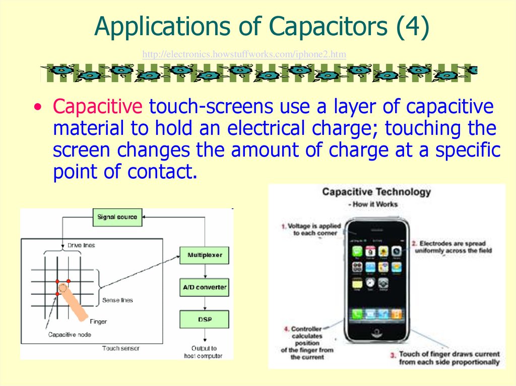
Applications of Capacitors (4)http://electronics.howstuffworks.com/iphone2.htm
• Capacitive touch-screens use a layer of capacitive
material to hold an electrical charge; touching the
screen changes the amount of charge at a specific
point of contact.
36.
Measuring Capacitance with reed switch37.
38.
Function of Dielectric• The dielectrics contain charged molecules which are
randomly oriented.
• When an external field is applied, by dropping a potential
across the two plates, the charged molecules align
themselves with the electric field (see Figure 2).
• This alignment of charges produces dipoles where the
positive charges of each molecule are in the direction of the
applied field and the negative charges oppose the field.
• An internal electric field, which is opposite in direction of
the external electric field, will result.
• Consequently a reduction of the overall electric field and
the overall potential occurs.
• Referring again to the definition of capacitance, if the
potential across the two plates is reduced, the capacitance
is increased.
39.
Useful Websiteshttp://www.splung.com/content/sid/3/page/capacitors
http://www.electronics-tutorials.ws/capacitor/cap_5.html
http://www.electronics2000.co.uk/calc/capacitor-code-calculator.php