 Физика
Похожие презентации:
")


Academic Article
1.
ArticleBlast diffusion by different shapes of vehicle hull
Abstract: In many parts of the world, the blast is a frequent occurrence case. Blast damages
humans as well to the property. The physics of blast is very complicated for analysis. Hence,
researcher have been studying physics of anti-vehicular (AV) mine explosion, explosive
interaction with soil, gas expansion, interaction of explosive product with vehicles, human
effects from AV mine explosion etc. Many strategies were discussed to mitigate the blast effect.
To protect the military vehicle, many design measures are suggested. One of the measures could
be the effective design of the shape of vehicle hull, which can dissipate blast energy in effective
way. An analytical study on blast energy dissipation through different shaped hull of military
vehicle is discussed in this paper. These vehicle hulls have same cross sectional perimeter and
length is also kept same. Various responses after blast are studied on these hulls and comparison
is done for an effective dissipation of blast energy.
Keywords: AV mine explosion, vehicle hull, energy of explosion, energy dissipation, finite
element analysis
1. Introduction
In recent past the terrorist attacks and guerrilla warfare are becoming more and more
frequent. Hence the research on protection against landmine threats to army vehicles, buildings
and personnel have been having an increasing role. Many researched have been studying the
complicated chemistry of the blast and identifying measures to mitigate the blast energy.
Ramasamy et al. (2009) gave a glimpse on anti-vehicular (AV) mines and their damages;
mitigate the blast effect, enhancement of armor on the base of the vehicle etc. They highlighted
the physics of AV mine explosion, explosive interaction with soil, gas expansion, interaction
of explosive product with vehicles, human effects from AV mine explosion etc. Many strategies
were discussed to mitigate the blast effect. Olson et al. and Nurick (1993, 1995) analyzed
stiffened and un-stiffened clamped square mild steel plates under uniformly distributed blast
load. The strain rate sensitivity was predicted to unstiffened plate in different modes. Wang
(2001) presented a benchmark work of simulation of explosion in soil and air using LS-DYNA
commercial code and Eulerian formulation. From this report it appears that for a landmine
explosion simulation results are in a satisfactory agreement with experiments. Brill et al. (2000)
simulated mine blast using LS-DYNA on an armored personnel vehicle and compared to a full
test. Different approaches to the numerical analysis of this complicated event are presented and
results are compared. In particular the blast load is applied using the standard engineering model
(CONWEP) because of the obvious computational advantages of this approach. However, a
fully coupled finite element analysis simulating the interaction between the blast wave, the
detonation gases and the vehicle was also performed. The use of the LS-DYNA component
dummy models for the simulation of the occupants is also illustrated. The numerical simulations
using LS-DYNA hydro code were in good. In recent past the terrorist attacks and guerrilla
warfare are becoming more and more frequent. Hence the research on protection against
landmine threats to army vehicles, buildings and personnel have been having an increasing role.
Many researched have been studying the complicated chemistry of the blast and identifying
measures to mitigate the blast energy. Ramasamy et al. (2009) gave a glimpse on anti-vehicular
(AV) mines and their damages; mitigate the blast effect, enhancement of armor on the base of
the vehicle etc. They highlighted the physics of AV mine explosion, explosive interaction with
2.
soil, gas expansion, interaction of explosive product with vehicles, human effects from AVmine explosion etc. Many strategies were discussed to mitigate the blast effect. Olson et al. and
Nurick (1993, 1995) analyzed stiffened and un-stiffened clamped square mild steel plates under
uniformly distributed blast load. The strain rate sensitivity was predicted to unstiffened plate in
different modes. Wang (2001) presented a benchmark work of simulation of explosion in soil
and air using LS-DYNA commercial code and Eulerian formulation. From this report it appears
that for a landmine explosion simulation results are in a satisfactory agreement with
experiments. Brill et al. (2000) simulated mine blast using LS-DYNA on an armored personnel
vehicle and compared to a full test. Different approaches to the numerical analysis of this
complicated event are presented and results are compared. In particular the blast load is applied
using the standard engineering model (CONWEP) because of the obvious computational
advantages of this approach. However, a fully coupled finite element analysis simulating the
interaction between the blast wave, the detonation gases and the vehicle was also performed.
The use of the LS-DYNA component dummy models for the simulation of the occupants is also
illustrated. The numerical simulations using LS-DYNA hydro code were in good TM 5-8551(1986) by U.S. Department of army. This manual provides the procedures for the design and
analysis of protective structures subjected to the effects of conventional weapons.
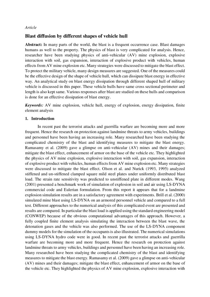
The typical hull shapes with same length and cross sectional perimeter is shown in Fig.
1.
Fig. 1: Different shapes of hull with same cross sectional perimeter and length
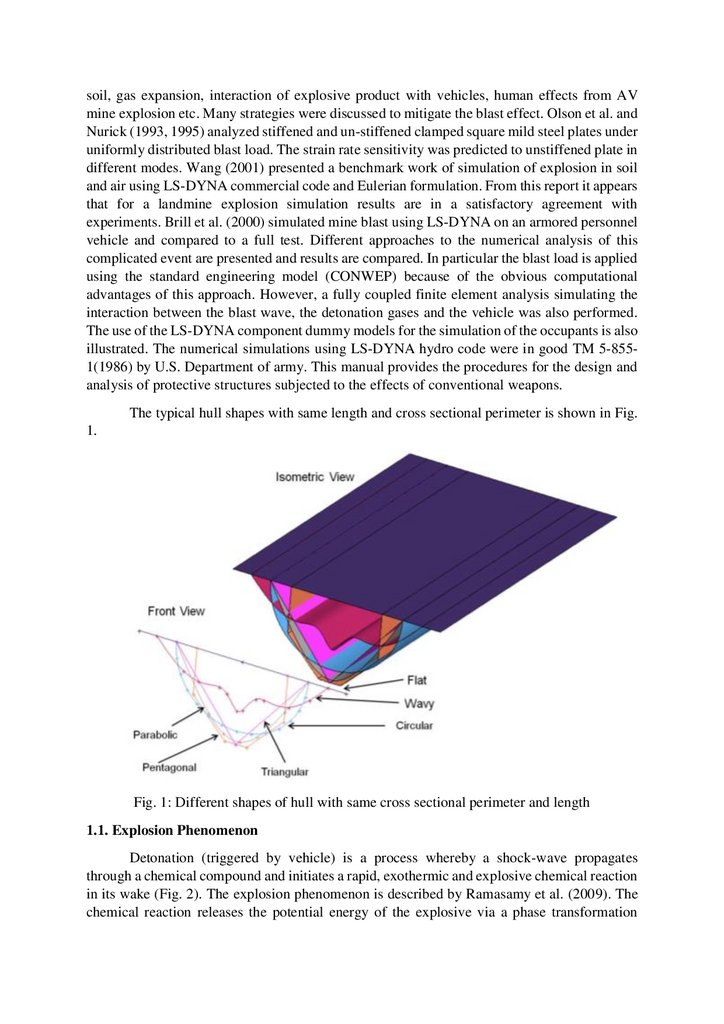
1.1. Explosion Phenomenon
Detonation (triggered by vehicle) is a process whereby a shock-wave propagates
through a chemical compound and initiates a rapid, exothermic and explosive chemical reaction
in its wake (Fig. 2). The explosion phenomenon is described by Ramasamy et al. (2009). The
chemical reaction releases the potential energy of the explosive via a phase transformation
3.
process. The detonation wave releases a mass of superheated and high-pressure gas. Thepressures are typically of the order of 1.4 – 3million psi whilst temperatures are of the order of
2000°C to 6000°C. For a landmine the detonation processes can be characterized by three
phases: explosive interaction with the soil, gas expansion to the surface and soil ejecta
interaction with the vehicle. In the present study the soil ejecta are not considered in calculation.
Fig. 2: Activation of the pressure fuses causing the initiation of the booster charge within the
landmine
2. Methodology
2.1. Finite Element (FE) Simulation
Finite element simulations were carried out for different hulls to study their response to
explosion as explained below.
2.2. FE Model Building through HyperMesh
The Altair product HyperMesh (2012) is used for FE model building. Hulls are
presented with shell elements at mid plane surface. Accurate FE model generated through
HyperMesh gave good solver convergence.
2.3. Solving the problem through LsDyna
LsDyna (2012) explicit solver is used for solving the attempted study. It offer wide
variety of material modeling and provide lot of contact algorithm according to situation.
2.3.1. FE setup
The structural behavior of an object or structure exposed to blast wave may be analyzed
by dealing with two main issues. Firstly, blast-loading effects, i.e., forces that are resulted
directly from the action of the blast pressure; secondly, the structural response, or the expected
damage criteria associated with such loading effects. It is important to consider the interaction
of the blast waves with the target structures. The structural response will depend upon the size,
shape and weight of the target. CONWEP load function was applied in order to generate the
blast equivalent pressure distribution on the hull. In LSDYNA CONWEP function is called
with *LOAD_BLAST card. This card uses computer program CONWEP (CONventional
4.
WEaPon) (1991). CONWEP assumes the following exponential decay of the pressure withtime.
where p(t) [kPa] is the pressure at time t, ps0 [kPa] is the peak incident pressure, T0 [ms]
is the positive phase duration, ‘A’ is the decay coefficient (dimensionless) and Tα [ms] is the
arrival time.
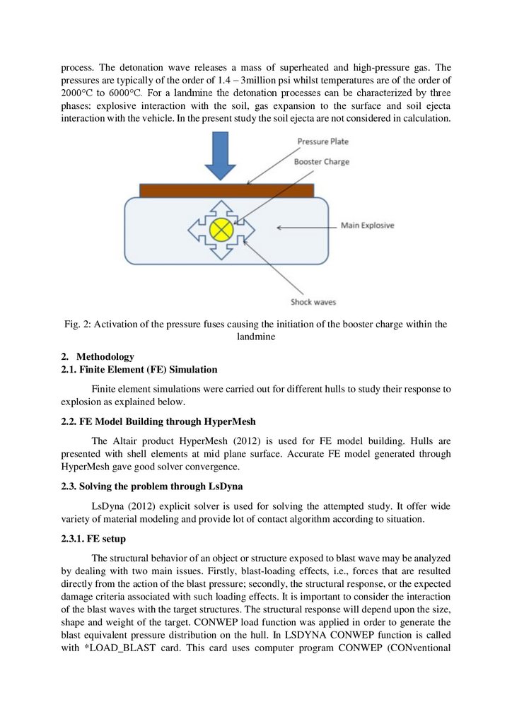
The inputs that it requires are the following: TNT equivalent mass; Stand-off distance;
Type of burst. The schematic to load function for this problem is shown in Fig. 3.
Fig. 3: Load function CONWEP
*LOAD_BLAST is used to define an air blast function for the application of pressure
loads from the detonation of conventional explosives. The implementation is based on a report
by Randers-Pehrson and Bannister (1997) where it is mentioned that this model is adequate for
use in engineering studies of vehicle responses due to the blast from land mines. This option
determines the pressure values when used in conjunction with the keywords: *LOAD_SHELL.
The compressibility of media (air) etc is beyond the scope of the study. The hull attached to
vehicle mass is free to move upward due to the blast. The hull is represented in mid plane by
Belytschko-LinTsay (1998) shell element in LSDyna which is computationally efficient
alternatives to other shell elements. It is assumed here that explosion is taking place on the land
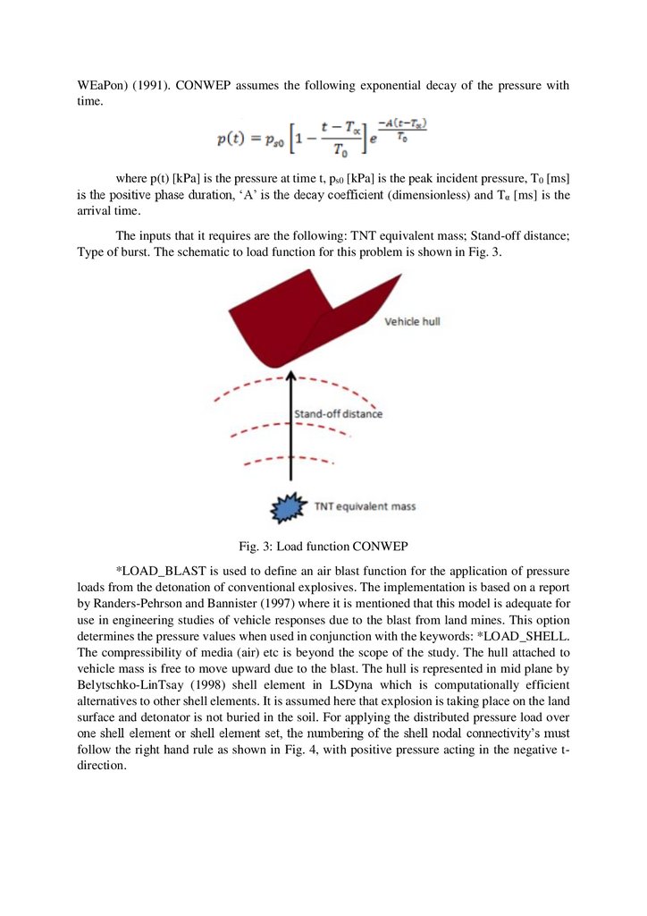
surface and detonator is not buried in the soil. For applying the distributed pressure load over
one shell element or shell element set, the numbering of the shell nodal connectivity’s must
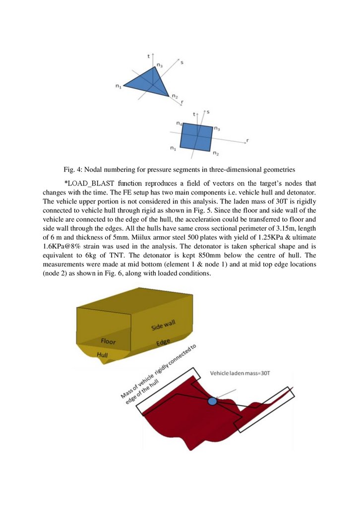
follow the right hand rule as shown in Fig. 4, with positive pressure acting in the negative tdirection.
5.
Fig. 4: Nodal numbering for pressure segments in three-dimensional geometries*LOAD_BLAST function reproduces a field of vectors on the target’s nodes that
changes with the time. The FE setup has two main components i.e. vehicle hull and detonator.
The vehicle upper portion is not considered in this analysis. The laden mass of 30T is rigidly
connected to vehicle hull through rigid as shown in Fig. 5. Since the floor and side wall of the
vehicle are connected to the edge of the hull, the acceleration could be transferred to floor and
side wall through the edges. All the hulls have same cross sectional perimeter of 3.15m, length
of 6 m and thickness of 5mm. Miilux armor steel 500 plates with yield of 1.25KPa & ultimate
1.6KPa@8% strain was used in the analysis. The detonator is taken spherical shape and is
equivalent to 6kg of TNT. The detonator is kept 850mm below the centre of hull. The
measurements were made at mid bottom (element 1 & node 1) and at mid top edge locations
(node 2) as shown in Fig. 6, along with loaded conditions.
6.
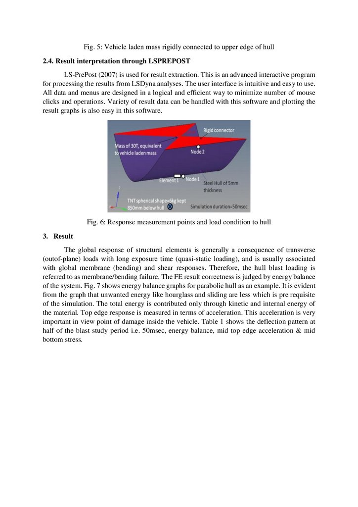
Fig. 5: Vehicle laden mass rigidly connected to upper edge of hull2.4. Result interpretation through LSPREPOST
LS-PrePost (2007) is used for result extraction. This is an advanced interactive program
for processing the results from LSDyna analyses. The user interface is intuitive and easy to use.
All data and menus are designed in a logical and efficient way to minimize number of mouse
clicks and operations. Variety of result data can be handled with this software and plotting the
result graphs is also easy in this software.
Fig. 6: Response measurement points and load condition to hull
3. Result
The global response of structural elements is generally a consequence of transverse
(outof-plane) loads with long exposure time (quasi-static loading), and is usually associated
with global membrane (bending) and shear responses. Therefore, the hull blast loading is
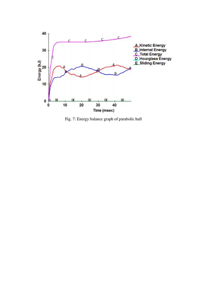
referred to as membrane/bending failure. The FE result correctness is judged by energy balance
of the system. Fig. 7 shows energy balance graphs for parabolic hull as an example. It is evident
from the graph that unwanted energy like hourglass and sliding are less which is pre requisite
of the simulation. The total energy is contributed only through kinetic and internal energy of
the material. Top edge response is measured in terms of acceleration. This acceleration is very
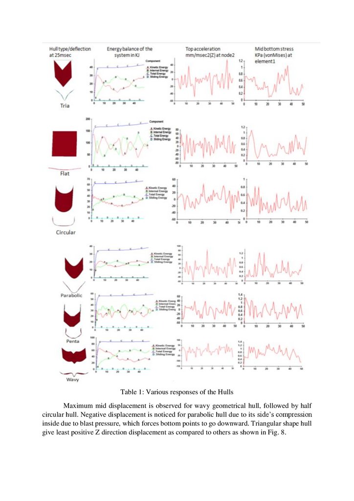
important in view point of damage inside the vehicle. Table 1 shows the deflection pattern at
half of the blast study period i.e. 50msec, energy balance, mid top edge acceleration & mid
bottom stress.
7.
Fig. 7: Energy balance graph of parabolic hull8.
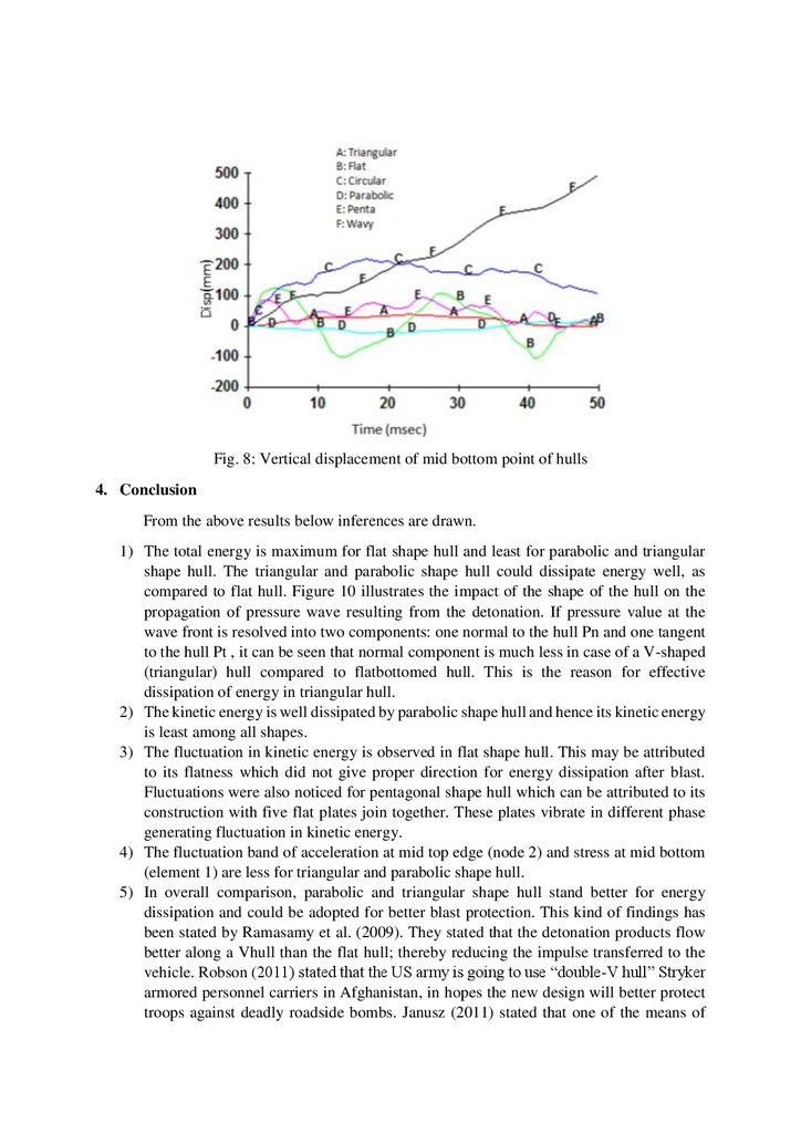
Table 1: Various responses of the HullsMaximum mid displacement is observed for wavy geometrical hull, followed by half
circular hull. Negative displacement is noticed for parabolic hull due to its side’s compression
inside due to blast pressure, which forces bottom points to go downward. Triangular shape hull
give least positive Z direction displacement as compared to others as shown in Fig. 8.
9.
Fig. 8: Vertical displacement of mid bottom point of hulls4. Conclusion
From the above results below inferences are drawn.
1) The total energy is maximum for flat shape hull and least for parabolic and triangular
shape hull. The triangular and parabolic shape hull could dissipate energy well, as
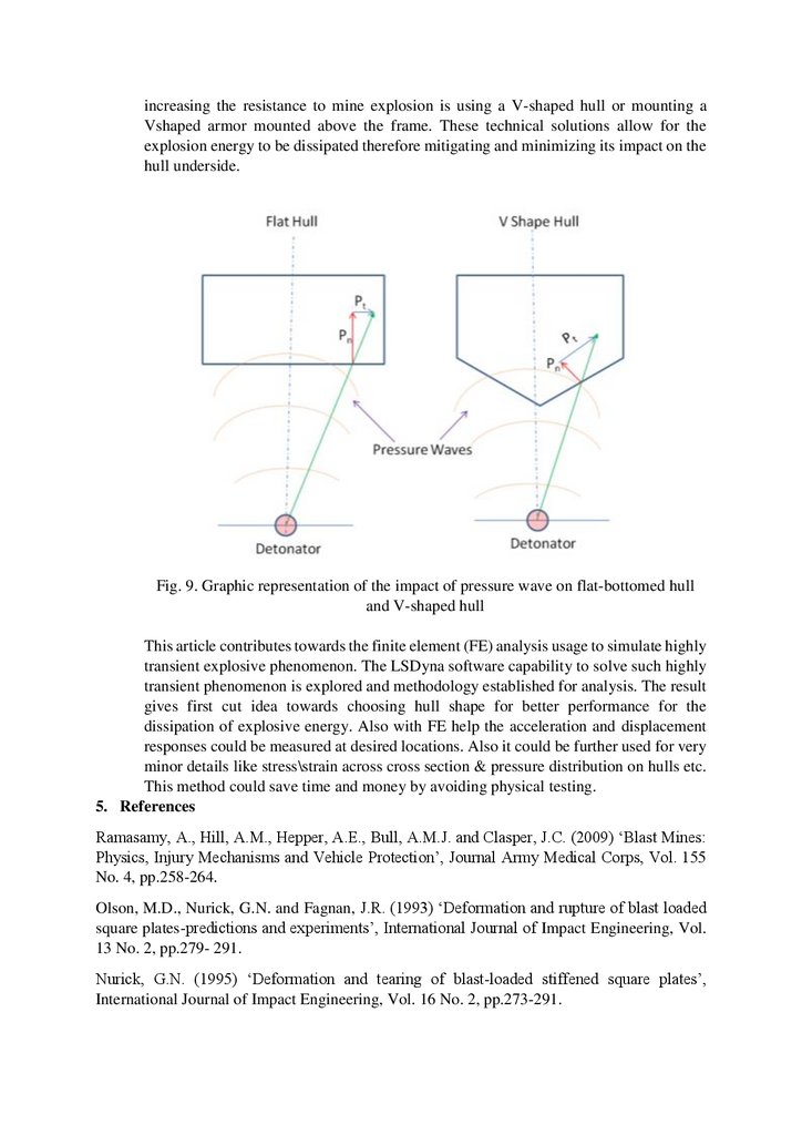
compared to flat hull. Figure 10 illustrates the impact of the shape of the hull on the
propagation of pressure wave resulting from the detonation. If pressure value at the
wave front is resolved into two components: one normal to the hull Pn and one tangent
to the hull Pt , it can be seen that normal component is much less in case of a V-shaped
(triangular) hull compared to flatbottomed hull. This is the reason for effective
dissipation of energy in triangular hull.
2) The kinetic energy is well dissipated by parabolic shape hull and hence its kinetic energy
is least among all shapes.
3) The fluctuation in kinetic energy is observed in flat shape hull. This may be attributed
to its flatness which did not give proper direction for energy dissipation after blast.
Fluctuations were also noticed for pentagonal shape hull which can be attributed to its
construction with five flat plates join together. These plates vibrate in different phase
generating fluctuation in kinetic energy.
4) The fluctuation band of acceleration at mid top edge (node 2) and stress at mid bottom
(element 1) are less for triangular and parabolic shape hull.
5) In overall comparison, parabolic and triangular shape hull stand better for energy
dissipation and could be adopted for better blast protection. This kind of findings has
been stated by Ramasamy et al. (2009). They stated that the detonation products flow
better along a Vhull than the flat hull; thereby reducing the impulse transferred to the
vehicle. Robson (2011) stated that the US army is going to use “double-V hull” Stryker
armored personnel carriers in Afghanistan, in hopes the new design will better protect
troops against deadly roadside bombs. Janusz (2011) stated that one of the means of
10.
increasing the resistance to mine explosion is using a V-shaped hull or mounting aVshaped armor mounted above the frame. These technical solutions allow for the
explosion energy to be dissipated therefore mitigating and minimizing its impact on the
hull underside.
Fig. 9. Graphic representation of the impact of pressure wave on flat-bottomed hull
and V-shaped hull
This article contributes towards the finite element (FE) analysis usage to simulate highly
transient explosive phenomenon. The LSDyna software capability to solve such highly
transient phenomenon is explored and methodology established for analysis. The result
gives first cut idea towards choosing hull shape for better performance for the
dissipation of explosive energy. Also with FE help the acceleration and displacement
responses could be measured at desired locations. Also it could be further used for very
minor details like stress\strain across cross section & pressure distribution on hulls etc.
This method could save time and money by avoiding physical testing.
5. References
Ramasamy, A., Hill, A.M., Hepper, A.E., Bull, A.M.J. and Clasper, J.C. (2009) ‘Blast Mines:
Physics, Injury Mechanisms and Vehicle Protection’, Journal Army Medical Corps, Vol. 155
No. 4, pp.258-264.
Olson, M.D., Nurick, G.N. and Fagnan, J.R. (1993) ‘Deformation and rupture of blast loaded
square plates-predictions and experiments’, International Journal of Impact Engineering, Vol.
13 No. 2, pp.279- 291.
Nurick, G.N. (1995) ‘Deformation and tearing of blast-loaded stiffened square plates’,
International Journal of Impact Engineering, Vol. 16 No. 2, pp.273-291.
11.
Wang, J. (2001) Simulation of landmine explosion using LS-DYNA 3D software. Benchmarkwork of simulation of explosion in soil and air, D.o.D.-W.S.D.A.a.M.R. Laboratory, Editor.
2001, DSTO Aeronautical and Maritime Research Laboratory, 506 Lorimer St Fishermans
Bend Vic 3207 Australia.
Brill, A., Cohen, B., Paul, A. and Bois, D. (2000) ‘Simulation of a mine blast effect on the
occupants of an APC’. Paper presented at 6th European LS-DYNA Users’ Conference, Detroit
2000.
Fallet, R. (2008) ‘Mine explosion and blast effect on vehicle analysis of the potential damages
on passengers’. Paper presented at 2nd European HyperWorks Technology Conference,
Strasbourg, September 30th – October 1st, 2008.
Tremblay, J., Bergeron, D.M., Gonzalez, R. (1998) ‘KTA 1-29: Protection of SoftSkinned
Vehicle Occupants from Landmine Effects’. In: Program TTCP, editor. ValBelair, Canada,
Defence Research Establishment Valcartier, Quebec, Canada
Schneck, W. (1994) ‘The Development of Mine Resistant Vehicles’. Virginia, USA.: Belvoir
RD&E Centre, Directorate CS.
Ngo, T., Mendis, P., Gupta, A. and Ramsay, J. (2007) ‘Blast loading and blast effects on
structures – an overview’, Electronics journal of structural engineering, special issue: loading
on structure, pp.76-91.
Held, Manfred (2009) ‘Anti-tank Mine Blast Effects’, Journal of Battlefield Technology, Vol.
12, No. 2, pp.1-7.
Craig, L. (1996) ‘Protection of Light Skinned Vehicles against Landmines - A Review’
Weapons Systems Division, Aeronautical and Maritime Research Laboratory, DSTO-TR-0310.
TM 5-855-1 (1986) ‘Fundamentals of Protective Design for Conventional Weapons’, U.S.
Department of the Army, Washington DC.
Hyde DW (1991). CONWEP: Conventional Weapons Effects Program. 1991: US Army
Engineer Waterways Experiment Station, USA.
Robson, S. (2011) ‘News-Army soon to field double –V hull strykers to protect against blasts’,
STARS and Stripes.
Janusz, S. (2011) ‘Protection of vehicles against mines’, Journal of KONES Powertrain and
Transport, Vol. 18, No. 1.
HyperMesh11 (2012). A product of Altair Engineering. HyperWorks, for fininite element preprocessing. www.altairhyperworks.com, 1820 E Big beavers, Troy, MI 48083.
LsDyna Version 971 R6.1.0 (2012). A program for nonlinear dynamic analysis of structures in
three dimensions, Livermore Software Technology Corporation 94550– 1740.