


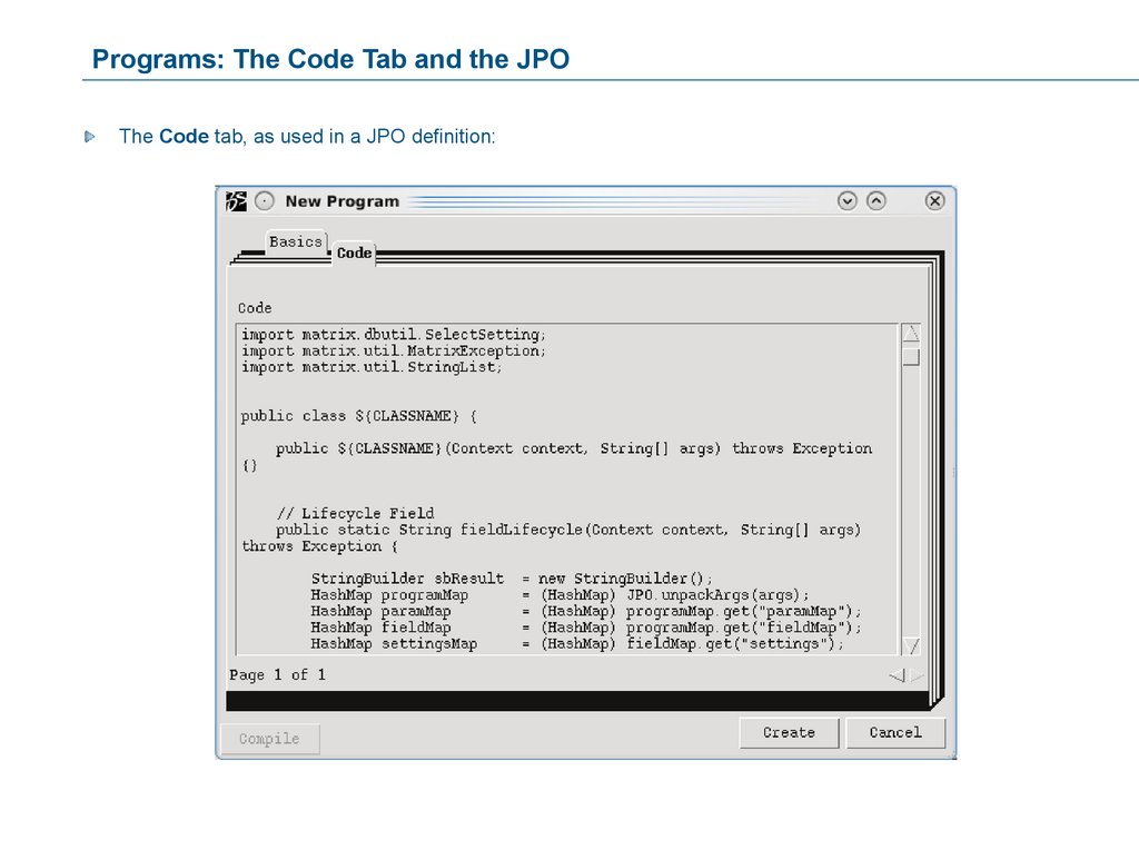


 Программное обеспечение
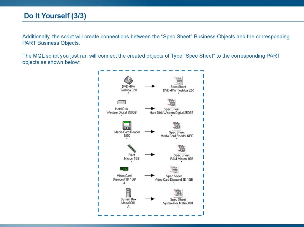
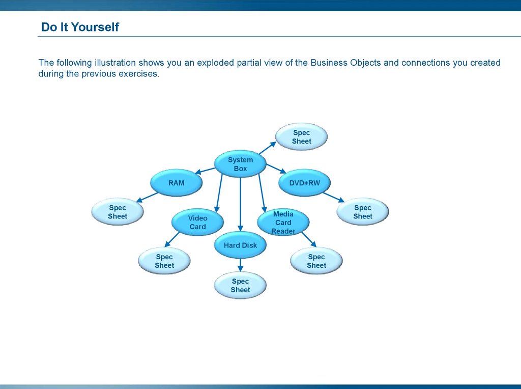
Похожие презентации:


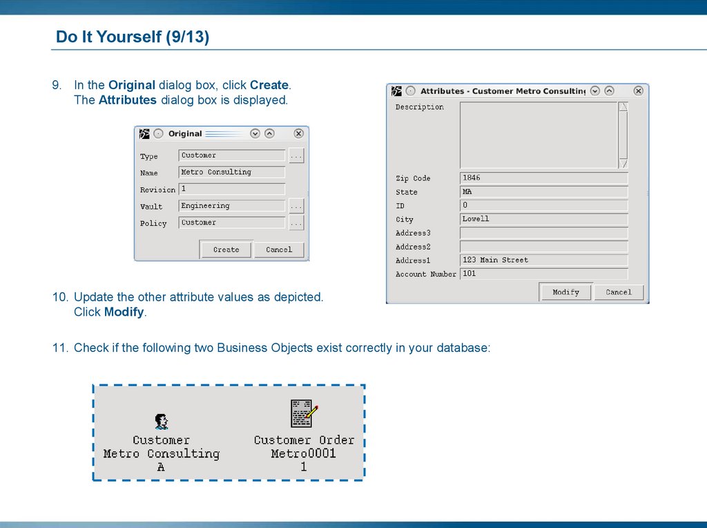
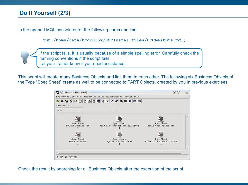
")


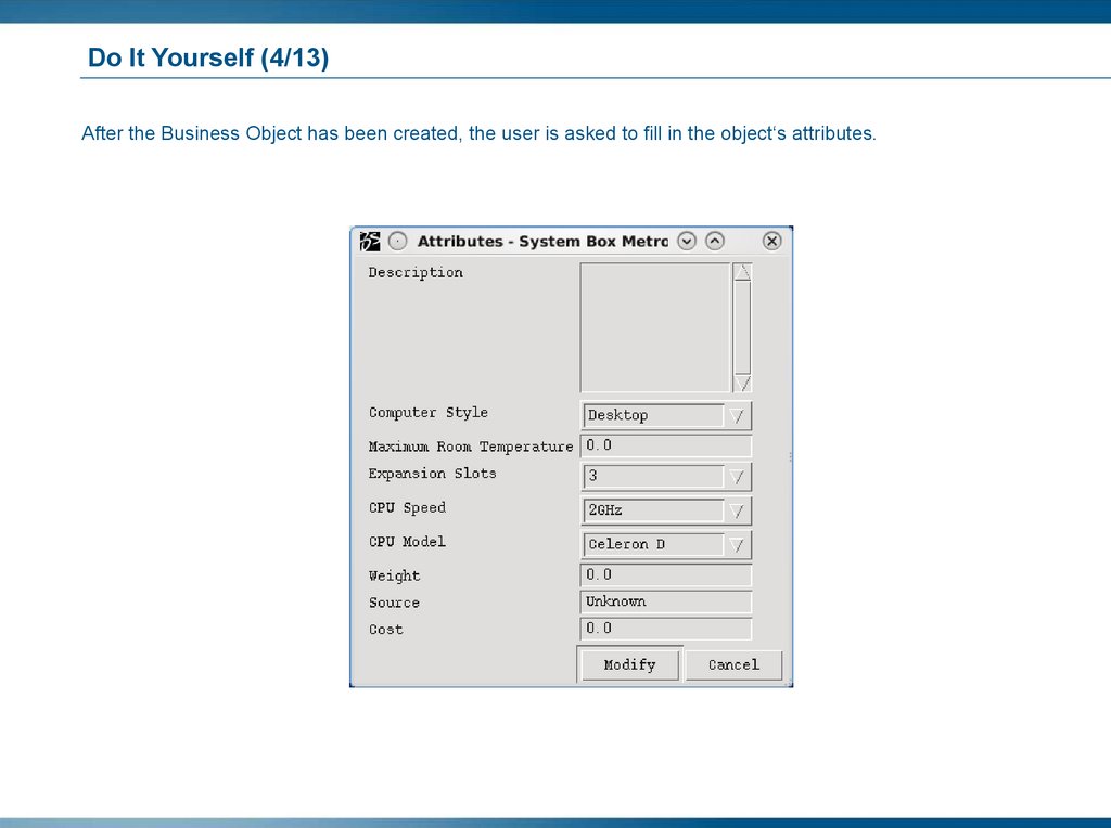
Environment requirements. The 3DEXPERIENCE R2015x platform
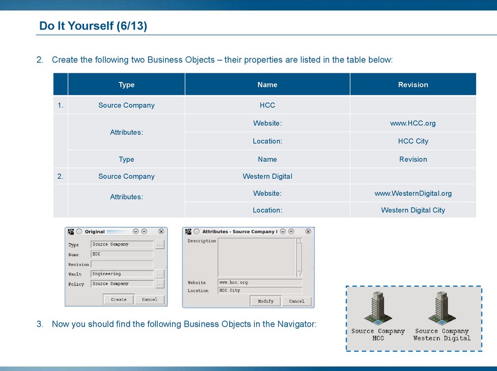
1.
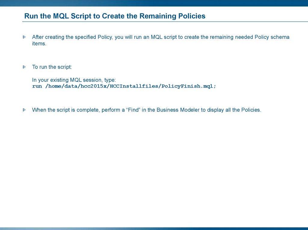
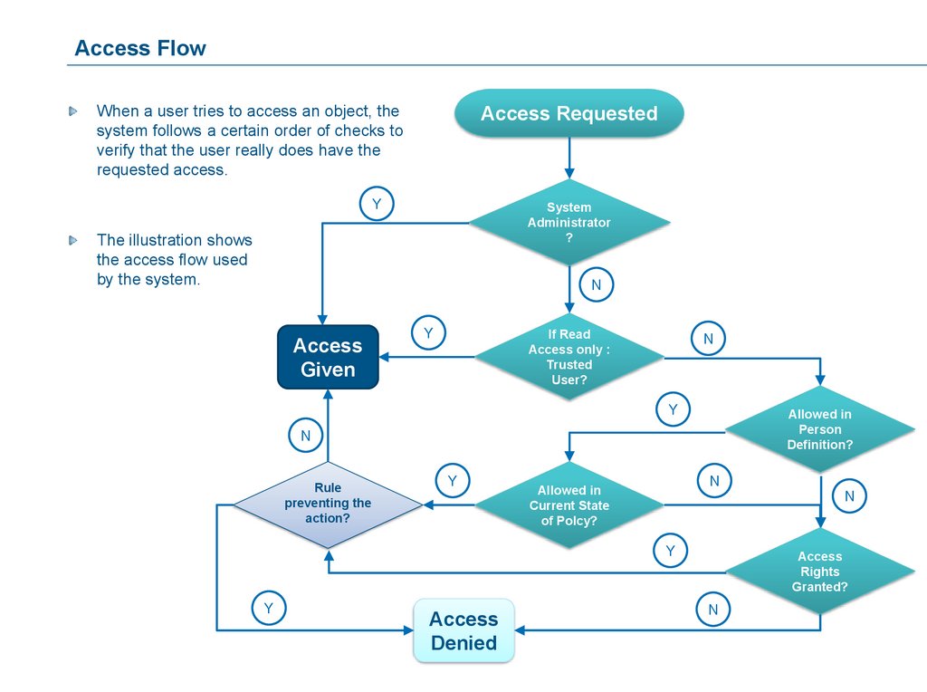
Environment RequirementsThis course does not contain any software installation files necessary to perform the exercises. In order to
practice, you must have access to a software installation and environment that includes:
The 3DEXPERIENCE R2015x platform
A course Data Package and/or Scripts: It contains the specific data files/documents needed to run the
exercises, which is imported into the server by a system administrator.
For complete information about the course environment, please refer to the detailed step document.
If you have any questions on how to access your environment, please contact your assigned support team. You
may also contact your education provider using the information on the Contact Us Page on Companion
Learning Space (Help > Contact Us menu.)
2.
Conventions Used in the Course (1/2)The following typographic conventions are used in this
course:
Bold text within a sentence denotes the name of a
tool, icon, window, dialog box, button or option.
Italic text within a sentence is used to denote the
name of a tree item or a data file, or to apply
emphasis on a key word.
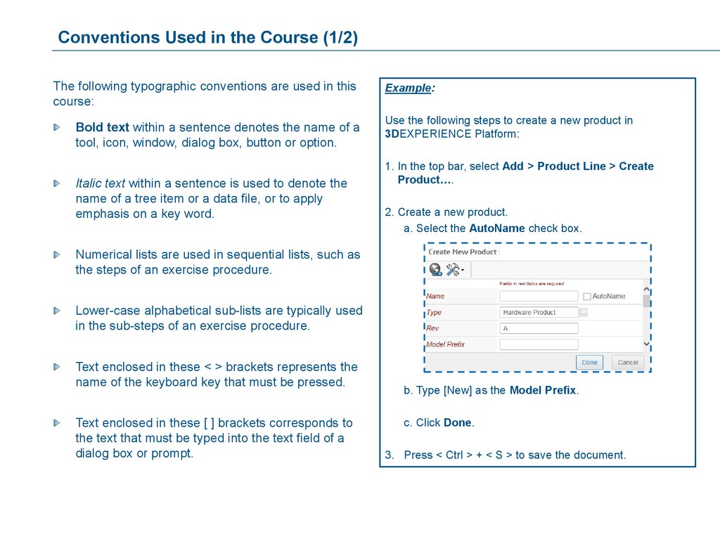
Example:
Use the following steps to create a new product in
3DEXPERIENCE Platform:
1. In the top bar, select Add > Product Line > Create
Product….
2. Create a new product.
a. Select the AutoName check box.
Numerical lists are used in sequential lists, such as
the steps of an exercise procedure.
Lower-case alphabetical sub-lists are typically used
in the sub-steps of an exercise procedure.
Text enclosed in these < > brackets represents the
name of the keyboard key that must be pressed.
Text enclosed in these [ ] brackets corresponds to
the text that must be typed into the text field of a
dialog box or prompt.
b. Type [New] as the Model Prefix.
c. Click Done.
3. Press < Ctrl > + < S > to save the document.
3.
Conventions Used in the Course (2/2)The following typographic conventions are used in this
course:
Examples:
3. Select the options as shown and click OK.
1
identifies an area or a group of objects in an
image that is associated with an instruction in a
sequential list or an exercise procedure.
3
A
identifies a specific entity in an image that is
associated with the corresponding text in a
sequential list or an exercise procedure.
Upper-case alphabetical lists are used for items that
are non-sequential, such as options or definitions.
You perform the following operations:
A. Create
B. Delete
C. Customize
A
at the top right corner of a slide indicates that
the slide contains animations. Click anywhere in
the contents area of the slide to view the animations.
B
C
4.
Business Modeling OverviewIn this lesson you will learn about the roles and responsibilities of a Business Administrator, the 3DEXPERIENCE
Platform schema and the 3DEXPERIENCE Open Studio Business Modeler environment. You will also learn how
to use the Browser to find information and navigate through the Administrative Objects.
Topics Covered:
1. The Tasks of a Business Administrator
2. The Workflow to Develop a 3DEXPERIENCE Platform Schema
3. Introduction to 3DEXPERIENCE Open Studio Business Modeler
4. The Browser Feature of the Business Modeler
2 hours
5.
Tasks of a Business AdministratorYou will learn about the tasks performed by a
Business Administrator. You will also become familiar
with the specific terminology used in this course.
Here are the topics to be covered:
1. The Tasks of a Business
Administrator
2. The Workflow to Develop a
3DEXPERIENCE Platform Schema
3. Introduction to 3DEXPERIENCE
Open Studio Business Modeler
4. The Browser Feature of the Business
Modeler
6.
Specific TerminologySchema: This is the data model in the database.
It is the specific configuration of the database including what can be created, what is allowed, how things are
controlled, and how they interact with each other. In short, the schema is unique to each business and
business problem, and it specifies the rules for what is stored and who has access to the stored information.
3DEXPERIENCE Open Studio Business Modeler: This is the business modeling software.
It is a thick-client software application (part of the 3DEXPERIENCE Open Studio) used to model and manage
the schema in On-Premise installation.
Business Administrator: This is the person who will be setting up the schema.
3DEXPERIENCE Open Studio: This is a collection of thick-client software applications used for creating,
managing and extracting information to and from the database in an administrative capacity, one of which is
the Business Modeler application.
7.
Business Administrator TasksThe main tasks that make up the job of a Business Administrator are:
Setting up the 3DEXPERIENCE Platform after installation
Defining / managing the schema
Creating / modifying the definitions
Testing and updating the schema
Maintaining the system for users
8.
Business Administration Concerns (1/2)How many Business Administrators?
Business Administration access can be assigned to more than one individual, allowing for a team of
administrators. If so, it is imperative that you accurately document all changes so as not to undo what another
team member has already done.
Be careful when altering the database.
Changes to the database may have significant consequences. The database will remain operational during
any schema change, but you will need to limit major changes until such time as database maintenance can be
performed.
The Business Administrator controls what and when changes are made.
9.
Business Administration Concerns (2/2)Always try the changes FIRST in a test database.
Changes should never be implemented without thorough testing within a test database, which should be a
copy of your Production database.
Start small and grow your schema.
You can start almost anywhere using the 3DEXPERIENCE Platform and grow your defined system as the
need arises.
Start with an area that you know well.
10.
SummaryThe Tasks of a Business Administrator
Schema: This is the data model in the database.
3DEXPERIENCE Open Studio Business
Modeler: This is the business modeling software.
Business Administrator: This is the person who
will be setting up the schema.
3DEXPERIENCE Open Studio: This is a collection
of thick-client software applications used for
creating, managing and extracting information to
and from the database in an administrative
capacity, one of which is the Business Modeler
application.
Business Administration access can be assigned to
more than one individual, allowing for a team of
administrators.
11.
The Workflow to Develop a 3DEXPERIENCE Platform SchemaYou will learn how to set up a 3DEXPERIENCE
Platform schema.
Here are the topics to be covered:
1. The Tasks of a Business
Administrator
2. The Workflow to Develop a
3DEXPERIENCE Platform Schema
3. Introduction to 3DEXPERIENCE
Open Studio Business Modeler
4. The Browser Feature of the Business
Modeler
12.
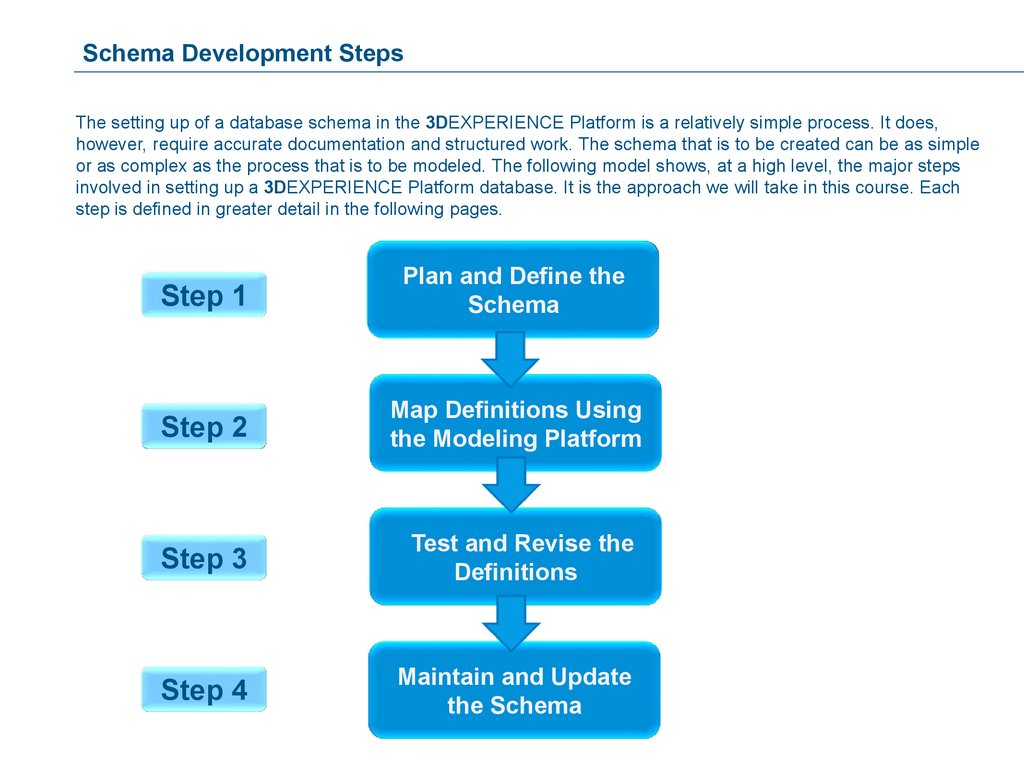
Schema Development StepsThe setting up of a database schema in the 3DEXPERIENCE Platform is a relatively simple process. It does,
however, require accurate documentation and structured work. The schema that is to be created can be as simple
or as complex as the process that is to be modeled. The following model shows, at a high level, the major steps
involved in setting up a 3DEXPERIENCE Platform database. It is the approach we will take in this course. Each
step is defined in greater detail in the following pages.
Step 1
Plan and Define the
Schema
Step 2
Map Definitions Using
the Modeling Platform
Step 3
Test and Revise the
Definitions
Step 4
Maintain and Update
the Schema
13.
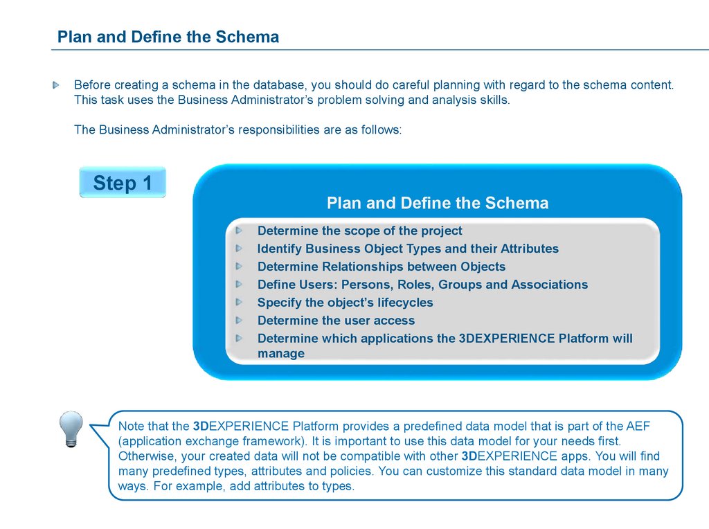
Plan and Define the SchemaBefore creating a schema in the database, you should do careful planning with regard to the schema content.
This task uses the Business Administrator’s problem solving and analysis skills.
The Business Administrator’s responsibilities are as follows:
Step 1
Plan and Define the Schema
Determine the scope of the project
Identify Business Object Types and their Attributes
Determine Relationships between Objects
Define Users: Persons, Roles, Groups and Associations
Specify the object’s lifecycles
Determine the user access
Determine which applications the 3DEXPERIENCE Platform will
manage
Note that the 3DEXPERIENCE Platform provides a predefined data model that is part of the AEF
(application exchange framework). It is important to use this data model for your needs first.
Otherwise, your created data will not be compatible with other 3DEXPERIENCE apps. You will find
many predefined types, attributes and policies. You can customize this standard data model in many
ways. For example, add attributes to types.
14.
Map Definitions Using the Modeling PlatformThe Business Administrator must create and/or modify the definitions used in the 3DEXPERIENCE Platform
database.
Step 2
Map Definitions Using the Modeling Platform
After installation, the database contains only the common
Business Processes Services schema:
Only OOTB administrative users exist: “creator”, “Test
Everything”, etc.
The Business Administrator enters the administrative definitions
or modifies an existing schema using:
Business Modeler
Matrix Query Language (MQL)*
* This topic is discussed in detail in the 3DEXPERIENCE MQL course and “Web Application
Customization – Fundamentals” course.
15.
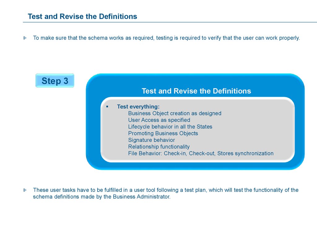
Test and Revise the DefinitionsTo make sure that the schema works as required, testing is required to verify that the user can work properly.
Step 3
Test and Revise the Definitions
Test everything:
Business Object creation as designed
User Access as specified
Lifecycle behavior in all the States
Promoting Business Objects
Signature behavior
Relationship functionality
File Behavior: Check-in, Check-out, Stores synchronization
These user tasks have to be fulfilled in a user tool following a test plan, which will test the functionality of the
schema definitions made by the Business Administrator.
16.
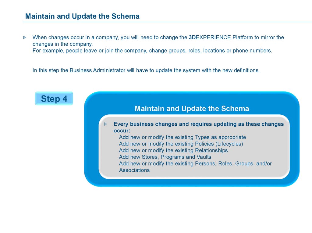
Maintain and Update the SchemaWhen changes occur in a company, you will need to change the 3DEXPERIENCE Platform to mirror the
changes in the company.
For example, people leave or join the company, change groups, roles, locations or phone numbers.
In this step the Business Administrator will have to update the system with the new definitions.
Step 4
Maintain and Update the Schema
Every business changes and requires updating as these changes
occur:
Add new or modify the existing Types as appropriate
Add new or modify the existing Policies (Lifecycles)
Add new or modify the existing Relationships
Add new Stores, Programs and Vaults
Add new or modify the existing Persons, Roles, Groups, and/or
Associations
17.
SummaryThe Workflow to Develop a 3DEXPERIENCE Platform Schema
Before creating a schema in the database, you
should do careful planning with regard to the
schema content.
The Business Administrator must create and/or
modify the definitions used in the 3DEXPERIENCE
Platform database.
Ensure that the schema works as required
When changes occur in a company, you will need
to change the 3DEXPERIENCE Platform to mirror
the changes in the company.
Plan and Define the
Schema
Map Definitions Using
the Modeling Platform
Test and Revise the
Definitions
Maintain and Update
the Schema
18.
Introduction to the 3DEXPERIENCE Studio Business ModelerYou will be introduced to the user interface of the
Business Modeler, its menus and their functions.
Here are the topics to be covered:
1. The Tasks of a Business
Administrator
2. The Workflow to Develop a
3DEXPERIENCE Platform Schema
3. Introduction to 3DEXPERIENCE
Open Studio Business Modeler
4. The Browser Feature of the Business
Modeler
19.
3DEXPERIENCE Studio Business Modeler– An Overview (1/2)The Business Modeler allows to work with the biggest part of 3DEXPERIENCE Platform configuration, stored
in the DB.
The data objects managed by the Business Modeler are called Administrative Objects.
3DEXPERIENCE Platform Business Administrators use the Business Modeler to set up the schema (data
model). This activity is the focus of this course.
3DEXPERIENCE Platform Application Developers use the Business Modeler to configure the web user
interface. This activity is not the focus of this course. It will be covered in the WAC (web application
configuration) courses.
20.
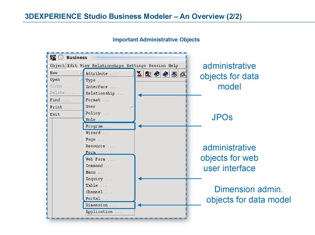
3DEXPERIENCE Studio Business Modeler – An Overview (2/2)Important Administrative Objects
administrative
objects for data
model
JPOs
administrative
objects for web
user interface
Dimension admin.
objects for data model
21.
Starting the 3DEXPERIENCE Open Studio Business ModelerYou can start the Matrix Navigator by:
selecting Start > Programs > Dassault Systemes EnoviaV6Server 3DEXPERIENCE R2015x >
Business on Windows-platforms.
Launching the script /home/data/RTV/enoviaV6R2015x/studio/scripts/business.sh on UNIXplatforms.
22.
The Business Modeler User InterfaceThe different user interface elements are shown below:
Title Bar
Menu Bar
Tool Bar
Work Area
Scroll Bars
Status Bar
23.
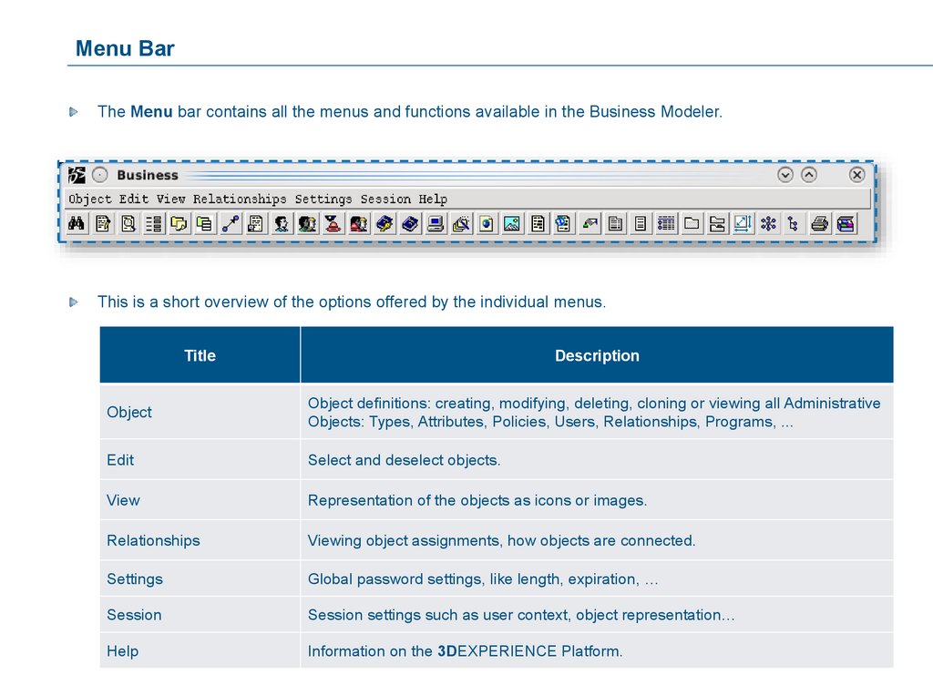
Menu BarThe Menu bar contains all the menus and functions available in the Business Modeler.
This is a short overview of the options offered by the individual menus.
Title
Description
Object
Object definitions: creating, modifying, deleting, cloning or viewing all Administrative
Objects: Types, Attributes, Policies, Users, Relationships, Programs, ...
Edit
Select and deselect objects.
View
Representation of the objects as icons or images.
Relationships
Viewing object assignments, how objects are connected.
Settings
Global password settings, like length, expiration, …
Session
Session settings such as user context, object representation…
Help
Information on the 3DEXPERIENCE Platform.
24.
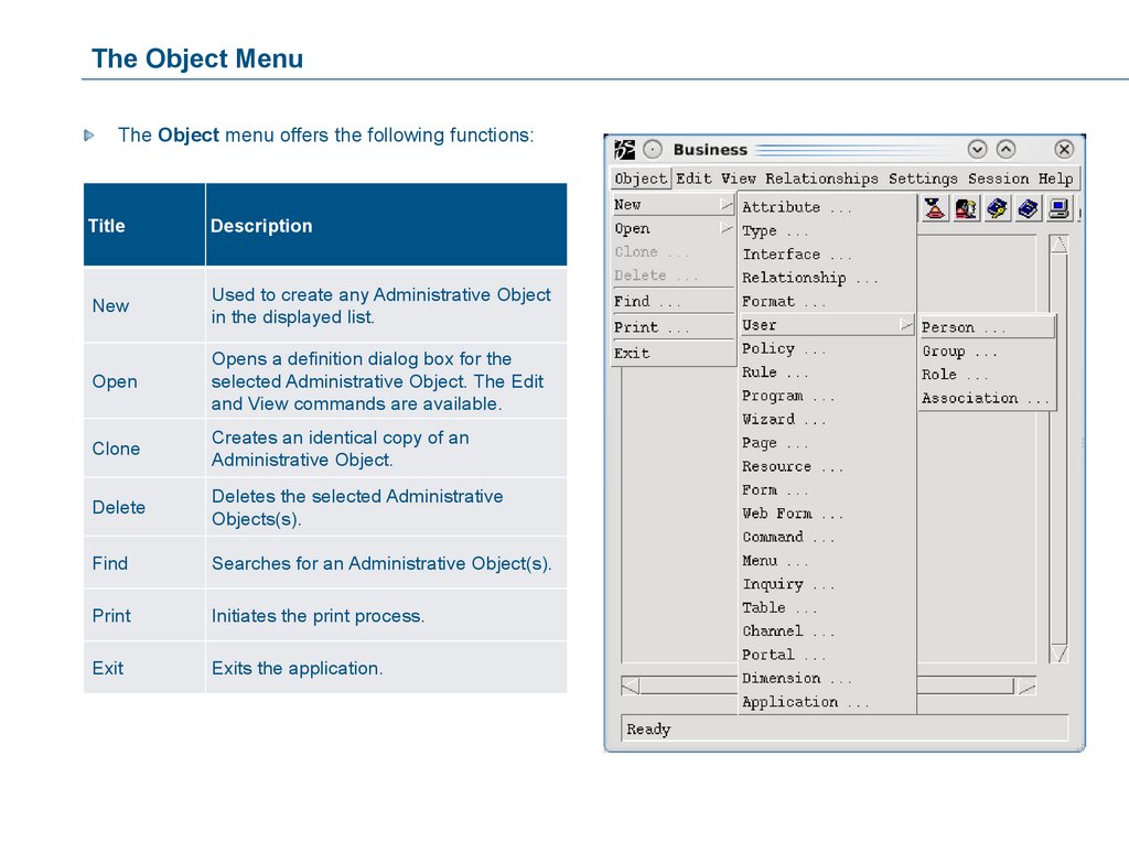
The Object MenuThe Object menu offers the following functions:
Title
Description
New
Used to create any Administrative Object
in the displayed list.
Open
Opens a definition dialog box for the
selected Administrative Object. The Edit
and View commands are available.
Clone
Creates an identical copy of an
Administrative Object.
Delete
Deletes the selected Administrative
Objects(s).
Find
Searches for an Administrative Object(s).
Initiates the print process.
Exit
Exits the application.
25.
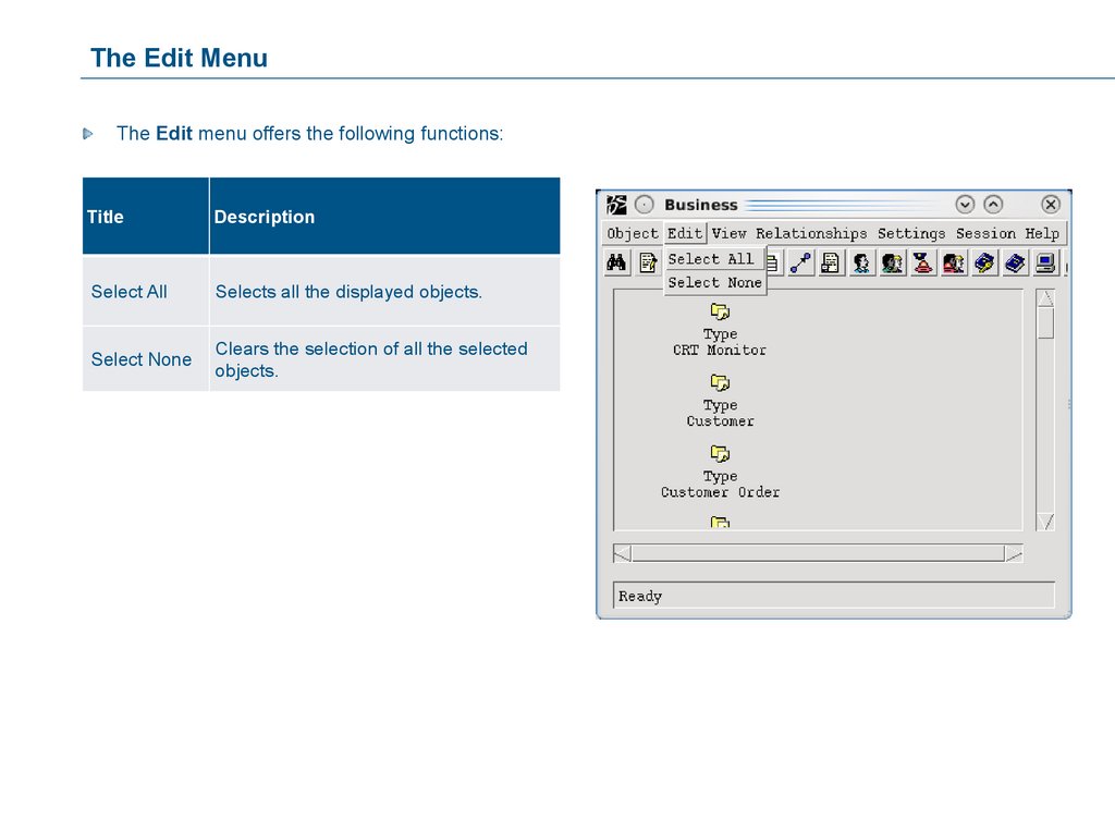
The Edit MenuThe Edit menu offers the following functions:
Title
Description
Select All
Selects all the displayed objects.
Select None
Clears the selection of all the selected
objects.
26.
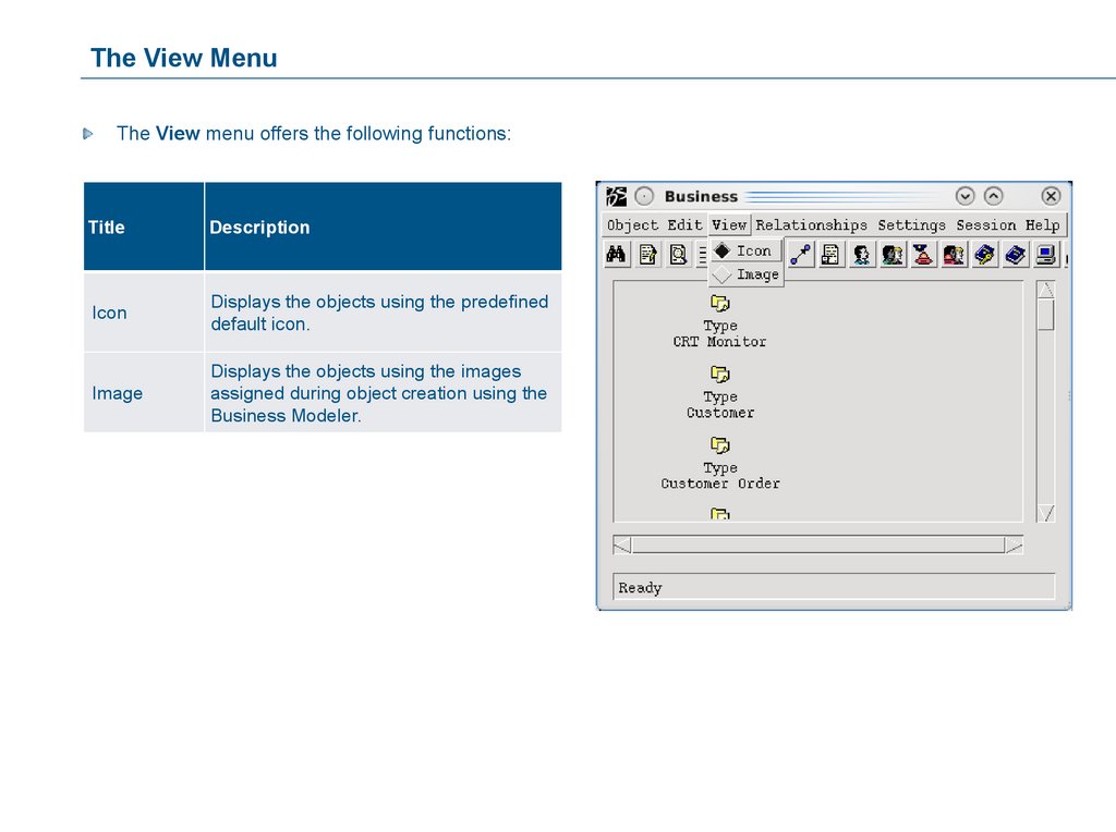
The View MenuThe View menu offers the following functions:
Title
Description
Icon
Displays the objects using the predefined
default icon.
Image
Displays the objects using the images
assigned during object creation using the
Business Modeler.
27.
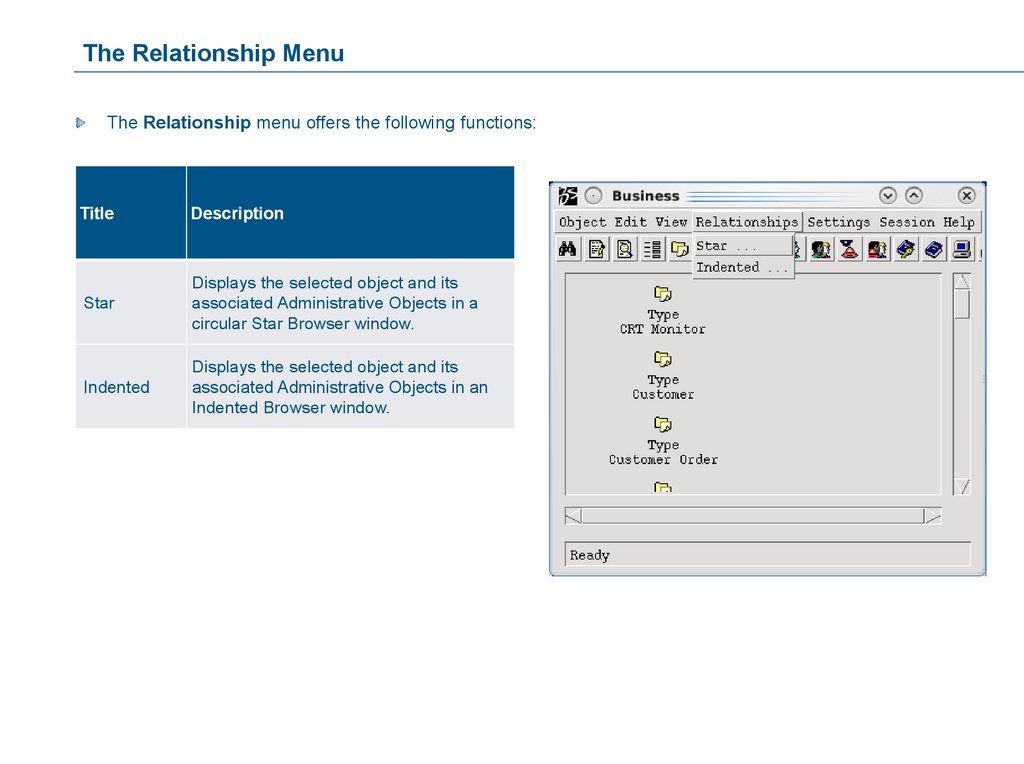
The Relationship MenuThe Relationship menu offers the following functions:
Title
Description
Star
Displays the selected object and its
associated Administrative Objects in a
circular Star Browser window.
Indented
Displays the selected object and its
associated Administrative Objects in an
Indented Browser window.
28.
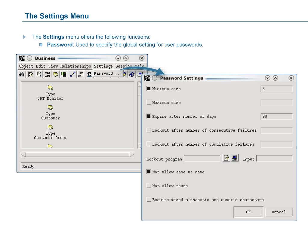
The Settings MenuThe Settings menu offers the following functions:
Password: Used to specify the global setting for user passwords.
29.
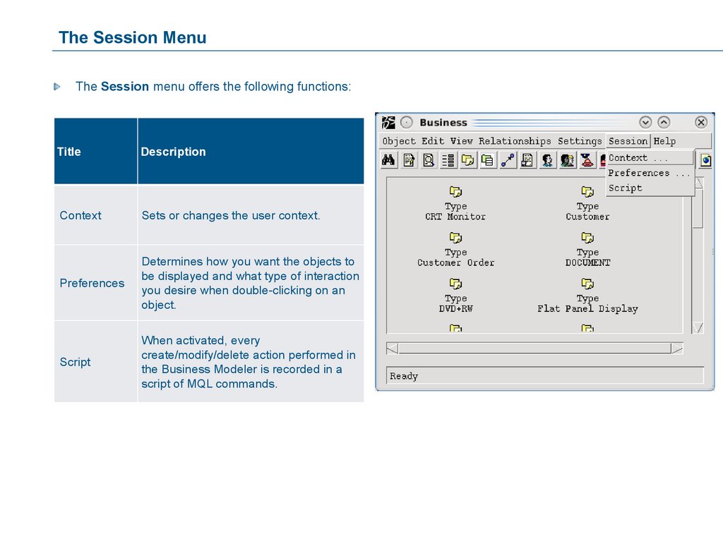
The Session MenuThe Session menu offers the following functions:
Title
Description
Context
Sets or changes the user context.
Preferences
Determines how you want the objects to
be displayed and what type of interaction
you desire when double-clicking on an
object.
Script
When activated, every
create/modify/delete action performed in
the Business Modeler is recorded in a
script of MQL commands.
30.
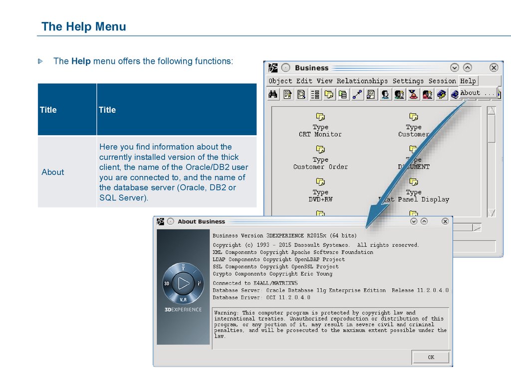
The Help MenuThe Help menu offers the following functions:
Title
Title
About
Here you find information about the
currently installed version of the thick
client, the name of the Oracle/DB2 user
you are connected to, and the name of
the database server (Oracle, DB2 or
SQL Server).
31.
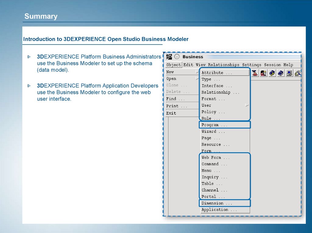
SummaryIntroduction to 3DEXPERIENCE Open Studio Business Modeler
3DEXPERIENCE Platform Business Administrators
use the Business Modeler to set up the schema
(data model).
3DEXPERIENCE Platform Application Developers
use the Business Modeler to configure the web
user interface.
32.
The Browser Feature of the Business ModelerYou will learn how to use the browser of the Business
Modeler to find information and to navigate through
the Administrative Objects.
Here are the topics to be covered:
1. The Tasks of a Business
Administrator
2. The Workflow to Develop a
3DEXPERIENCE Platform Schema
3. Introduction to 3DEXPERIENCE
Open Studio Business Modeler
4. The Browser Feature of the
Business Modeler
33.
The Browser in the Business ModelerUnlike the Navigator Browser in the 3DEXPERIENCE Open Matrix Navigator application, the Browser in the
Business Modeler does not display explicitly created relationships between objects.
Instead, it displays the Administrative Objects that are associated with the selected one. These objects
become associated during the definition of the individual Administrative Objects.
For example:
When you create a Type, you specify the Attributes that will be used by this Type. This creates an
association of Attributes-to-Type, which can be viewed in the Browser.
Or
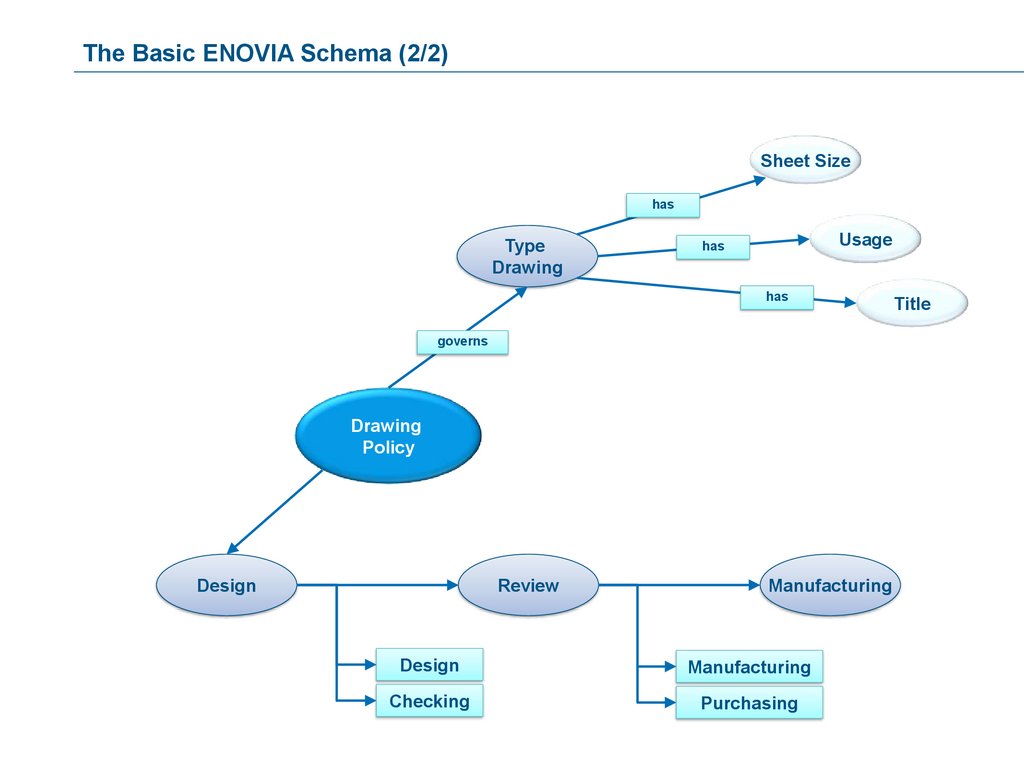
When you create a Policy, you specify the Types that will be governed by this Policy. This creates
the association between the Type and the Policy, which can be viewed in the Browser.
34.
Use of the Browser in the Business ModelerThe Browser is a useful tool for every Business Administrator to find out the connections between the
Administrative Objects, i.e. how the Administrative Objects are associated with each other.
This is especially needed when the end users report certain system behavior to the Business Administrator,
who has the task of finding out the reason for the system behavior by checking how the objects are
associated.
For example, this information may include Types, Child Types, Parent Types, Attributes, governing Policy,
allowed Relationships, etc.
35.
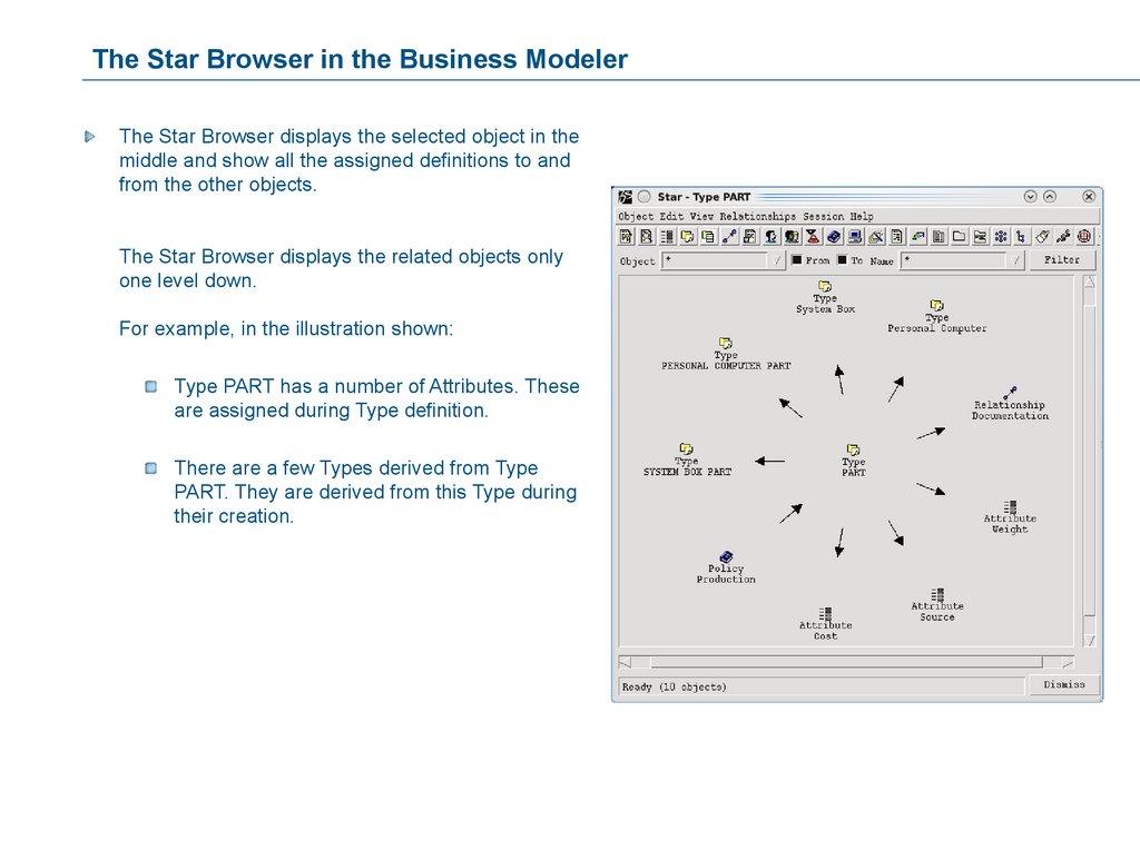
The Star Browser in the Business ModelerThe Star Browser displays the selected object in the
middle and show all the assigned definitions to and
from the other objects.
The Star Browser displays the related objects only
one level down.
For example, in the illustration shown:
Type PART has a number of Attributes. These
are assigned during Type definition.
There are a few Types derived from Type
PART. They are derived from this Type during
their creation.
36.
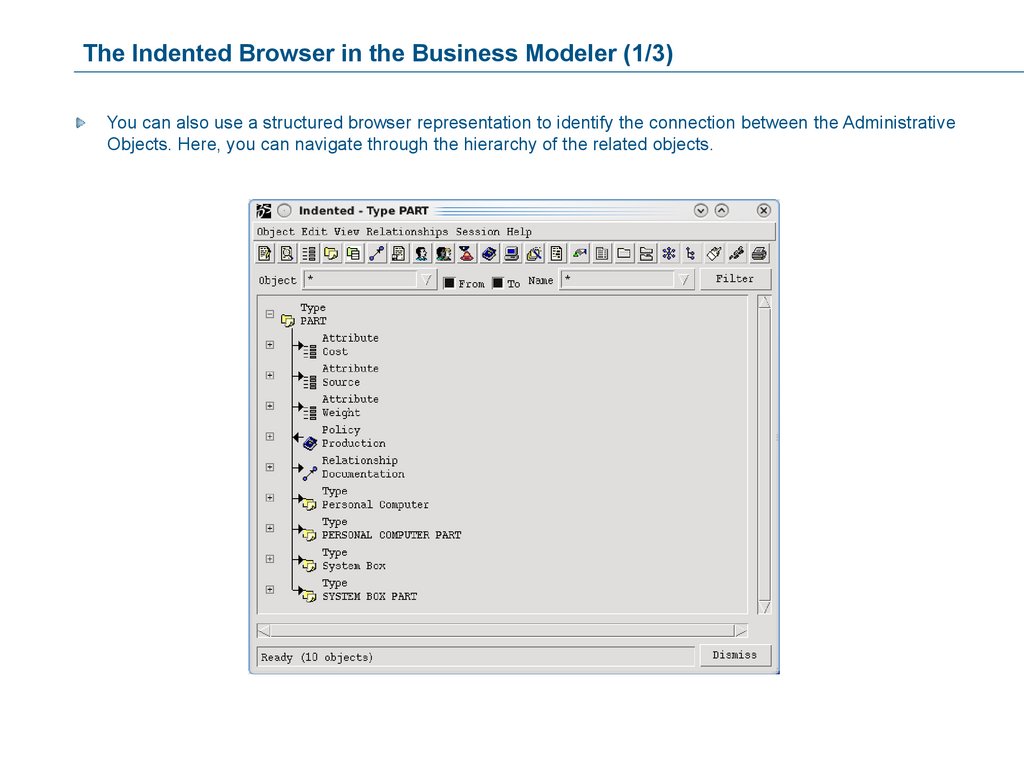
The Indented Browser in the Business Modeler (1/3)You can also use a structured browser representation to identify the connection between the Administrative
Objects. Here, you can navigate through the hierarchy of the related objects.
37.
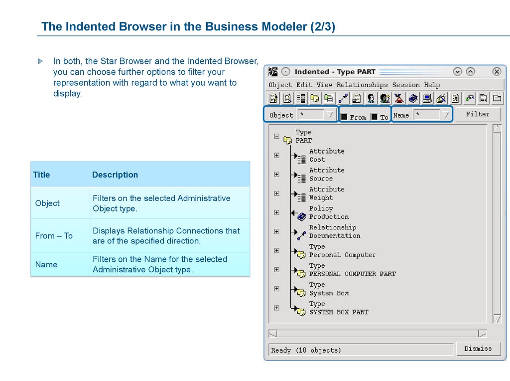
The Indented Browser in the Business Modeler (2/3)In both, the Star Browser and the Indented Browser,
you can choose further options to filter your
representation with regard to what you want to
display.
Title
Description
Object
Filters on the selected Administrative
Object type.
From – To
Displays Relationship Connections that
are of the specified direction.
Name
Filters on the Name for the selected
Administrative Object type.
38.
The Indented Browser in the Business Modeler (3/3)No Filter
Filtered for Attributes
Filtered for Attributes
starting with S
39.
SummaryThe Browser Feature of the Business Modeler
The Star Browser displays the selected object in
the middle and show all the assigned definitions to
and from the other objects.
You can also use a structured browser
representation to identify the connection between
the Administrative Objects. Here, you can navigate
through the hierarchy of the related objects.
40.
The Concepts of 3DEXPERIENCE Platform SchemaYou will first learn about the components of an
ENOVIA schema.
You will then learn how to define an ENOVIA schema
and name its concept details.
Here are the topics to be covered:
1. The Concepts of 3DEXPERIENCE
Platform Schema
2. Case Study Overview
3. Dimensions, Attributes and Types
4. Relationships
5. Programs
6. Persons, Groups, Roles and
Associations
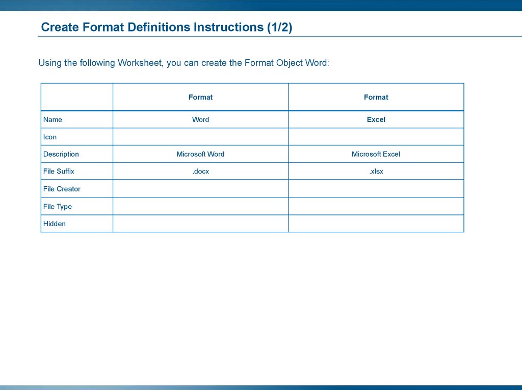
7. Files and Formats
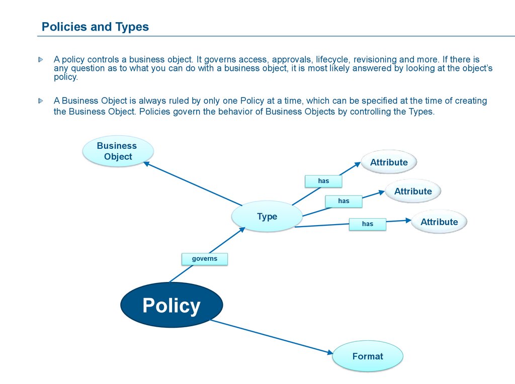
8. Policies
9. Rules
41.
The 3DEXPERIENCE Platform SchemaA 3DEXPERIENCE Platform schema is a collection of Administrative Objects that are needed for the end
users to create their business data.
It includes Business Object Types and their associated object Attributes. Each Type is governed by a Policy
that contains at least one State, which can specify one or more Formats.
A schema also involves Dimensions, Program Objects, Vaults, Stores, Relationships, Rule(s) and an
organizational model consisting of Persons, Roles, Groups and/or Associations.
Additional schema items may include Applications and Interfaces, as well as various Configurable
Components for creating graphic displays and enabling the end-user functionality in the User Interface.
42.
3DEXPERIENCE Platform Schema ConceptsAll 3DEXPERIENCE Platform databases have a schema.
The schema can be used out of the box (OOTB) by the Customer, if it completely fits to the customer’s needs.
If minor changes are planned to be done, like adding attributes to the OOTB types, then consider to use OneClick Deployment mechanisms and power of Unified Typing. A special training course is provided:
3DEXPERIENCE One-Click Deployment Experience.
If the company wants to take advantage of all powerful customization options, then 3DEXPERIENCE Open
Studio Applications can be used in more complex situations. Then:
The schema became completely unique and environment has the status so called “Customer Specific
Environment”.
Since every Customer Specific Environment is unique, there is no standard with regard to the
implementation time or configured (non-OOTB) functionality. Every schema needs its own evaluation on
these points.
The schema should result from careful planning and analysis, and should be documented.
43.
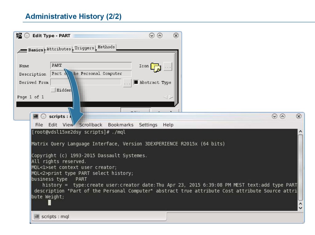
Administrative History (1/2)3DEXPERIENCE Open Studio automatically captures and records the modifications made to administrative
schema objects to provide a complete audit trail of how the system capabilities have evolved over time.
History entries are recorded against all administrative schema objects for Create and Modify events.
Admin history entries track the business administrator user name, event date, action, and a descriptive string
summarizing the change consistent with the business object history records.
44.
Administrative History (2/2)45.
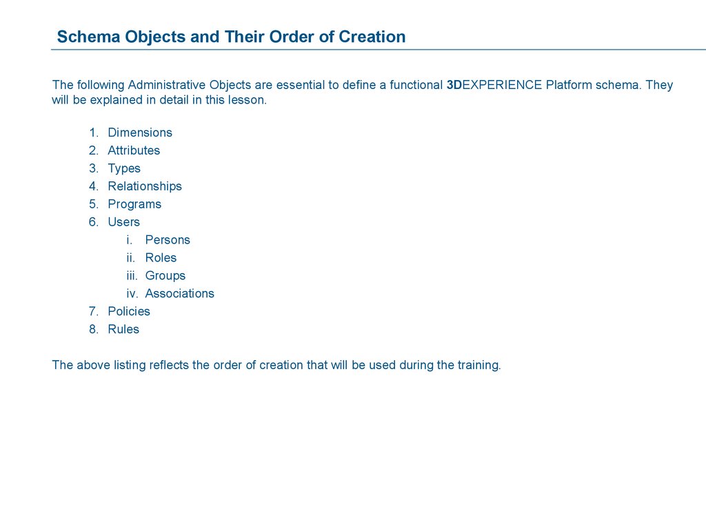
Schema Objects and Their Order of CreationThe following Administrative Objects are essential to define a functional 3DEXPERIENCE Platform schema. They
will be explained in detail in this lesson.
1.
2.
3.
4.
5.
6.
Dimensions
Attributes
Types
Relationships
Programs
Users
i. Persons
ii. Roles
iii. Groups
iv. Associations
7. Policies
8. Rules
The above listing reflects the order of creation that will be used during the training.
46.
Order of Creation (1/2)The recommended order of creation of Administrative Objects follows a simple rule:
Create a schema item only if all the required items to be assigned already exist.
As an example: When creating a Type, it may need Attributes, Trigger Programs and Methods. You should first
create the needed Attributes and Trigger Programs, and only then create the Type.
This is the most efficient mode of creation, in which you will only have to work with the Type definition once,
because all the required components will be available during creation.
The same applies to a Type that needs to be governed by a Policy.
It is recommended to first create the Type, then the Policy, and then directly assign the Type as the Governed
Type to the Policy. This eliminates the need to go back to the Policy.
47.
Order of Creation (2/2)For Persons, Groups and Roles, it is not important which Administrative Object is created first.
For example, you can first create a Person and assign it to a Role later or first create the Role and assign it to
the Person later. In both cases you do not have to go back to the first Administrative Object.
The order of creation will be:
Dimensions, Attributes, Types, Relationships, Programs, Users, Policies and Rules.
In an actual production environment, a System Administrator would typically first create Vaults and Stores for
the object and file storage. Vaults and Stores are created using the 3DEXPERIENCE Open Studio MQL
console. These topics will be discussed later in the 3DEXPERIENCE Open Studio System Administration
course.
Usually, Programs can be created at any time by the developers.
48.
Customization OptionsUsing the 3DEXPERIENCE Open Studio Applications
is not the only way to configure the 3DEXPERIENCE
Platform. Moreover, this approach will become
obsolete in future releases and customization will be
done via web-interface tools.
There are three commands available under the
Experience Configuration menu that allows you to
perform business administration tasks as well as
simple customization, like adding a new Type or
Attributes.
49.
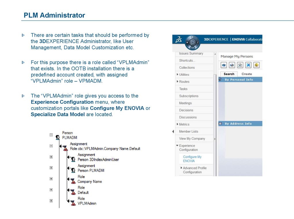
PLM AdministratorThere are certain tasks that should be performed by
the 3DEXPERIENCE Administrator, like User
Management, Data Model Customization etc.
For this purpose there is a role called “VPLMAdmin”
that exists. In the OOTB installation there is a
predefined account created, with assigned
“VPLMAdmin” role – VPMADM.
The “VPLMAdmin” role gives you access to the
Experience Configuration menu, where
customization portals like Configure My ENOVIA or
Specialize Data Model are located.
50.
User Management via the Web UITo create, modify and delete Users in the 3DEXPERIENCE Platform you can use the Studio Applications as
the core tools, but the preferred way to do this is to use the Configure My ENOVIA web-console:
51.
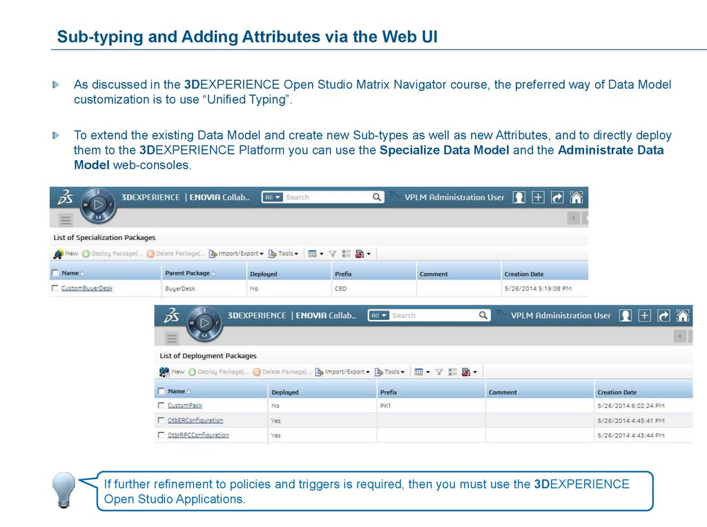
Sub-typing and Adding Attributes via the Web UIAs discussed in the 3DEXPERIENCE Open Studio Matrix Navigator course, the preferred way of Data Model
customization is to use “Unified Typing”.
To extend the existing Data Model and create new Sub-types as well as new Attributes, and to directly deploy
them to the 3DEXPERIENCE Platform you can use the Specialize Data Model and the Administrate Data
Model web-consoles.
If further refinement to policies and triggers is required, then you must use the 3DEXPERIENCE
Open Studio Applications.
52.
Tools for CustomizationIf a 3DEXPERIENCE Administrator has to resolve infrastructure issues, like working with distributed / multi-site
environments, then only the MQL tool can be used.
For implementation of completely new Types, the 3DEXPERIENCE Open Studio Business Modeler should be
used.
For general UI customization, a 3DDashboard with widget factory should be used.
Otherwise, to implement new UI components there are many ways to achieve your goal: either only with the
Business Modeler or with the help of JSPs and JPOs.
53.
SummaryThe Concepts of 3DEXPERIENCE Platform Schema
All 3DEXPERIENCE Platform databases have a
schema.
The schema is unique for each company that uses
the 3DEXPERIENCE Platform.
The schema should result from careful planning
and analysis, and should be documented.
If a 3DEXPERIENCE Administrator has to resolve
infrastructure issues, like working with distributed /
multi-site environments, then only the MQL tool can
be used.
For implementation of completely new Types, the
3DEXPERIENCE Open Studio Business Modeler
should be used.
For general UI customization, a 3DDashboard with
widget factory should be used.
Otherwise, to implement new UI components there
are many ways to achieve your goal: either only
with the Business Modeler or with the help of JSPs
and JPOs.
54.
Case Study OverviewYou will learn about the basic facts of the Case Study
that is going to be used to build the training data
model in this course.
Here are the topics to be covered:
1. The Concepts of 3DEXPERIENCE
Platform Schema
2. Case Study Overview
3. Dimensions, Attributes and Types
4. Relationships
5. Programs
6. Persons, Groups, Roles and
Associations
7. Files and Formats
8. Policies
9. Rules
55.
Case Study: BackgroundYou will perform the job of a Business Administrator and follow three of the four steps of Business
Administration (refer the first lesson for the steps).
You are the Business Administrator.
You will create the required Administrative Objects for the 3DEXPERIENCE Platform schema as
detailed in the Case Study.
The Case Study will be progressively disclosed.
Company name: Honest Computer Company (HCC)
Business description: Assembling Personal Computers and their components for sale.
56.
Case Study: ExercisesYou will be guided through the HCC Case Study exercises.
For each Administrative Object:
The use and the features will be discussed during the PowerPoint presentation.
The trainer will explain to you which steps to take to create the Administrative Object.
You will discuss the definition worksheets.
You will find all necessary information provided in the Case Study section.
57.
Case Study Introduction1. The following section will introduce you to the Case Study. The intention is to get familiar with the Honest
Computer Company (HCC), its tasks and its employees in order to be able to specify a data model.
2. This is the beginning of a Case Study that will span the rest of the course. In each topic, you will learn more
about the Honest Computer Company and the objects necessary for that topic.
3. Every effort has been made to make the Case Study realistic in terms of helping you practice the tasks and
duties of the Business Administrator. You will be asked to read the Case Study and then you will be given
instructions about what to do with the information contained in the Case Study.
4. The Case Study, which begins on the next page, is in narrative form. Read the Case Study and attempt to
understand the information that is presented. Visually compare the information you find in the Case Study
against the completed worksheets.
5. You will then create the Administrative Objects specified in the worksheets using the Business Administrator
application.
6. If certain information is not in the Case Study, leave it blank when creating your schema. For example, there
is no address, phone or fax information for the persons listed in this Case Study.
15 minutes
58.
Download the Course DataTo replay the exercises of this course, you need to download the data provided with the course.
Download the ‘hcc2015x.zip’ data file on your local workstation and put it into /home/data inside
3DEXPERIENCE Platform environment (VM Image) that has been provided to you.
Extract (unzip) the data using the ‘Extract archive here’ option.
This result hcc2015x folder contains various dummy documents that you will require while replaying the
scenario. Whenever you are asked to attach a document and/or import a file while replaying a step, you will find
it in this folder.
59.
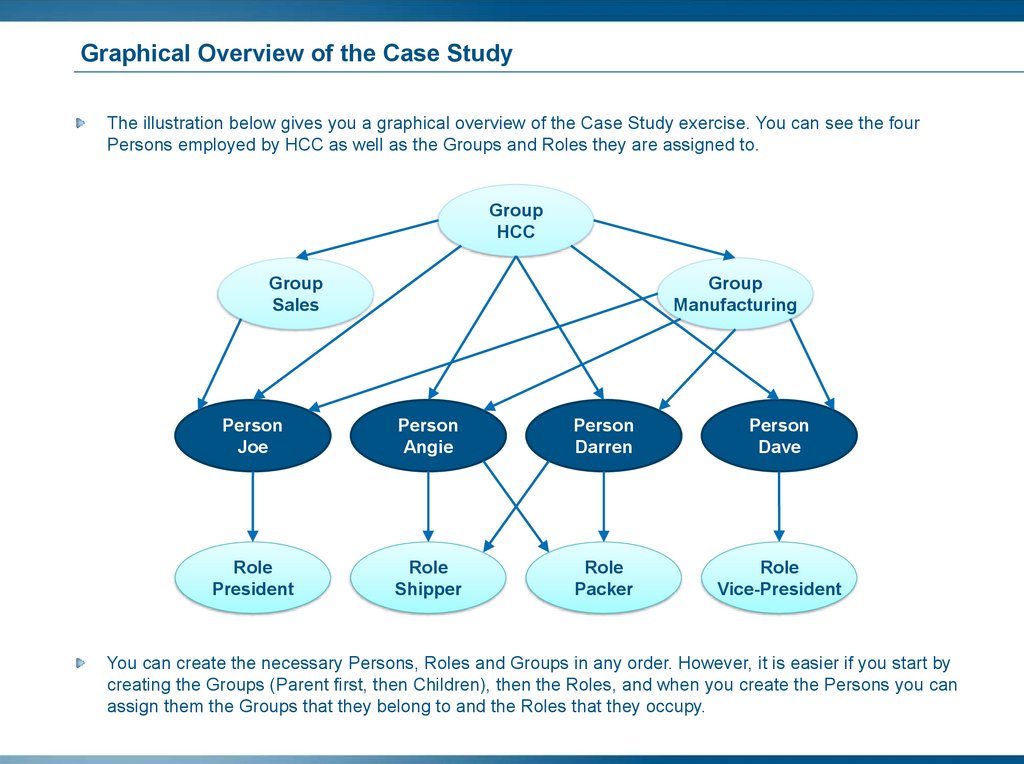
The CompanyThe Honest Computer Company (HCC) is a custom-build, personal computer company. They make personal
computers for customers who order via the telephone, mail-order and/or internet.
They started their business with two people, Joe and Dave. They have since grown to four people having added
Darren and Angie.
Joe and Dave will continue to be the principals in the company, responsible for actually building the computer
systems. Darren and Angie will take orders, provide customer service, package and ship the computers, and
send and receive the invoices.
HCC does not make printers, modems, scanners, or any other computer-related products.
60.
3DEXPERIENCE Platform at HCCThe Honest Computer Company currently tracks its customers, computer components, and accounting through
a paper-based system.
Joe and Dave want to deal with the chaos of their expanding business. They want to track their computer
products and the computer’s component parts information. They also want to keep track of what’s sold to each
customer.
They plan on instantiating a Customer Order object for each customer that places an order. Each Customer
Order object will “point” or “connect” to one or more computers that the particular customer may have ordered.
61.
Dimensions, Attributes and TypesYou will learn how to create Dimensions, Attributes
and Types as Administrative Objects for your
schema.
Here are the topics to be covered:
1. The Concepts of 3DEXPERIENCE
Platform Schema
2. Case Study Overview
3. Dimensions, Attributes and Types
4. Relationships
5. Programs
6. Persons, Groups, Roles and
Associations
7. Files and Formats
8. Policies
9. Rules
62.
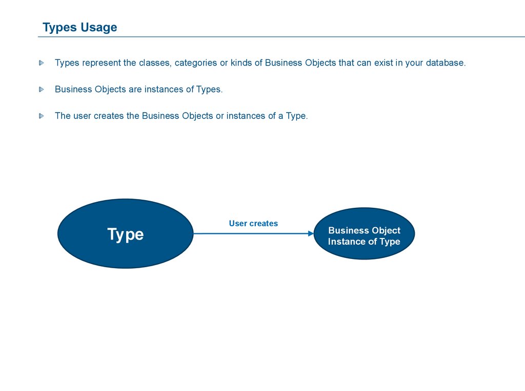
Types UsageTypes represent the classes, categories or kinds of Business Objects that can exist in your database.
Business Objects are instances of Types.
The user creates the Business Objects or instances of a Type.
User creates
Type
Business Object
Instance of Type
63.
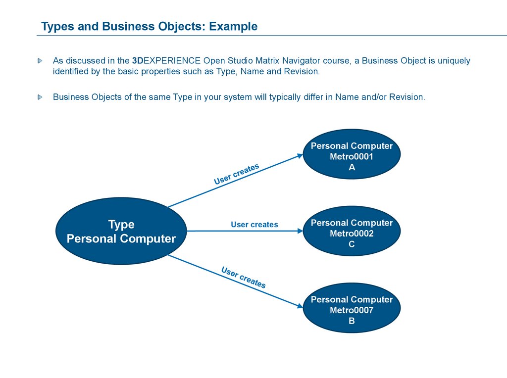
Types and Business Objects: ExampleAs discussed in the 3DEXPERIENCE Open Studio Matrix Navigator course, a Business Object is uniquely
identified by the basic properties such as Type, Name and Revision.
Business Objects of the same Type in your system will typically differ in Name and/or Revision.
Personal Computer
Metro0001
A
Type
Personal Computer
User creates
Personal Computer
Metro0002
C
Personal Computer
Metro0007
B
64.
Attributes UsageAttributes are the additional pieces of descriptive information used to specify the values associated with a
Business Object or a Relationship.
Business Objects:
Personal Computer
Metro0001
A
Has Attributes:
Cost: 275.00
Weight: 3.5 kg
Source: HCC
Relationships:
Personal Computer
Metro0001
A
Relationship
Personal Computer Assy
Attribute Quantity: 1
System Box
Metro0001
A
65.
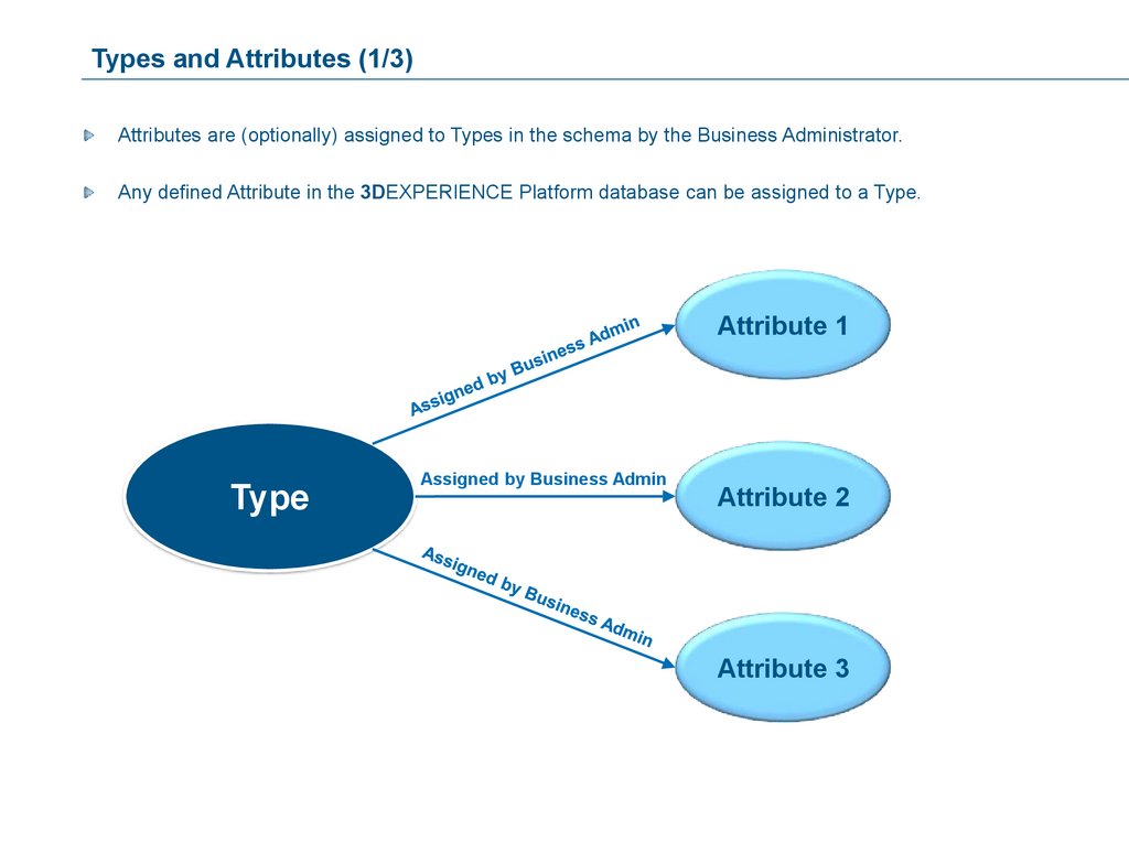
Types and Attributes (1/3)Attributes are (optionally) assigned to Types in the schema by the Business Administrator.
Any defined Attribute in the 3DEXPERIENCE Platform database can be assigned to a Type.
Attribute 1
Type
Assigned by Business Admin
Attribute 2
Attribute 3
66.
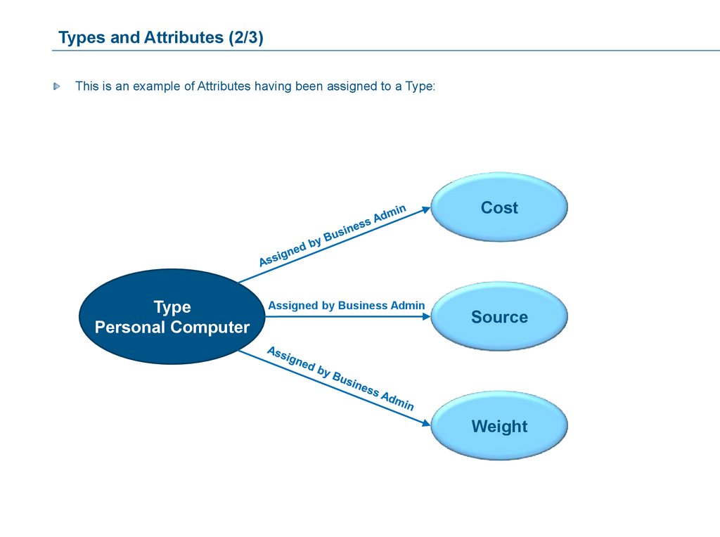
Types and Attributes (2/3)This is an example of Attributes having been assigned to a Type:
Cost
Type
Personal Computer
Assigned by Business Admin
Source
Weight
67.
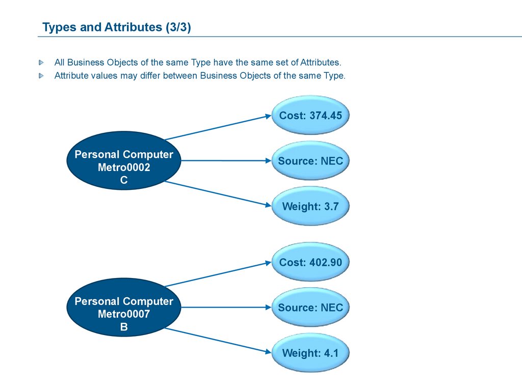
Types and Attributes (3/3)All Business Objects of the same Type have the same set of Attributes.
Attribute values may differ between Business Objects of the same Type.
Cost: 374.45
Personal Computer
Metro0002
C
Source: NEC
Weight: 3.7
Cost: 402.90
Personal Computer
Metro0007
B
Source: NEC
Weight: 4.1
68.
Dimensions Usage (1/6)Dimensions provide the ability to associate units of measure with an Attribute, and then display the value of
the Attribute (in a Table) using any/all of the units defined for that dimension.
For example, a dimension of Length could have units of Centimeter, Millimeter, Meter, Inch and Foot defined,
allowing the Length value to be displayed in a Table in any of the defined units.
69.
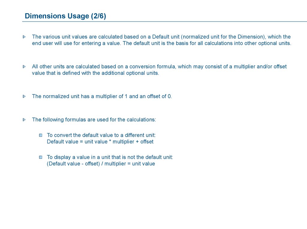
Dimensions Usage (2/6)The various unit values are calculated based on a Default unit (normalized unit for the Dimension), which the
end user will use for entering a value. The default unit is the basis for all calculations into other optional units.
All other units are calculated based on a conversion formula, which may consist of a multiplier and/or offset
value that is defined with the additional optional units.
The normalized unit has a multiplier of 1 and an offset of 0.
The following formulas are used for the calculations:
To convert the default value to a different unit:
Default value = unit value * multiplier + offset
To display a value in a unit that is not the default unit:
(Default value - offset) / multiplier = unit value
70.
Dimensions Usage (3/6)Example for the conversion between cm and inches:
Default unit: cm
Multiplier: 1
Optional unit: inch
Multiplier: 2.54
Offset: 0
Offset: 0
If the end user entered 12.45 as a value for the default unit, this would be calculated as follows:
for the default unit:
12.45 * 1 + 0 = 12.45 cm
for the optional unit:
(12.45 – 0) / 2.54 = 4.9015748 inches
If inch was the default unit, the calculation would be:
Default unit: inch
Multiplier: 1
Optional unit: cm
Multiplier: (1/2.54) = 0.39370079
Offset: 0
Offset: 0
for the default unit:
12.45 * 1 + 0 = 12.45 inch
for the optional unit:
(12.45 – 0) / 0.39370079 = 31.623 cm
In order to ensure an high level of precision during the conversion 12 digits are assumed for each
value.
71.
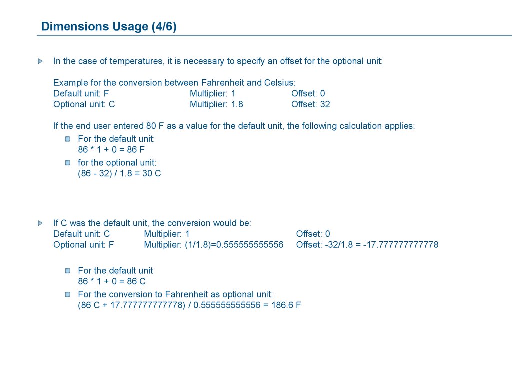
Dimensions Usage (4/6)In the case of temperatures, it is necessary to specify an offset for the optional unit:
Example for the conversion between Fahrenheit and Celsius:
Default unit: F
Multiplier: 1
Offset: 0
Optional unit: C
Multiplier: 1.8
Offset: 32
If the end user entered 80 F as a value for the default unit, the following calculation applies:
For the default unit:
86 * 1 + 0 = 86 F
for the optional unit:
(86 - 32) / 1.8 = 30 C
If C was the default unit, the conversion would be:
Default unit: C
Multiplier: 1
Optional unit: F
Multiplier: (1/1.8)=0.555555555556
Offset: 0
Offset: -32/1.8 = -17.777777777778
For the default unit
86 * 1 + 0 = 86 C
For the conversion to Fahrenheit as optional unit:
(86 C + 17.777777777778) / 0.555555555556 = 186.6 F
72.
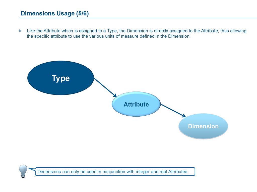
Dimensions Usage (5/6)Like the Attribute which is assigned to a Type, the Dimension is directly assigned to the Attribute, thus allowing
the specific attribute to use the various units of measure defined in the Dimension.
Type
Attribute
Dimension
Dimensions can only be used in conjunction with integer and real Attributes.
73.
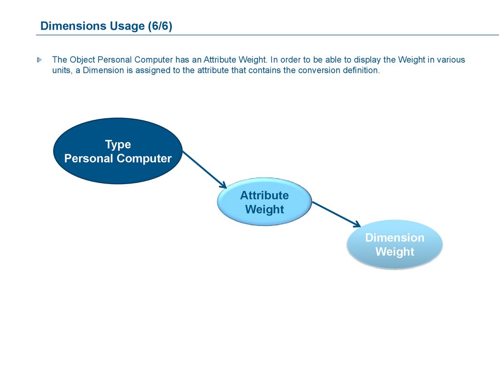
Dimensions Usage (6/6)The Object Personal Computer has an Attribute Weight. In order to be able to display the Weight in various
units, a Dimension is assigned to the attribute that contains the conversion definition.
Type
Personal Computer
Attribute
Weight
Dimension
Weight
74.
Creation of Types, Attributes and DimensionsThe creation order of the three Administrative Objects is:
1. Dimension
2. Attribute
3. Type
75.
Overview of Dimensions (1/6)The Dimension Administrative Object is assigned to an Attribute, thus providing the ability to associate units of
measure with an attribute value.
Dimensions are only used with Attributes of the type Real and Integer.
The definition of the units for a Dimension includes determining which unit will be the default (the normalized
unit for the Dimension) and the conversion formulas from that default unit to the other units.
The conversion formulas are based on a multiplier and an offset specified when the unit is defined.
76.
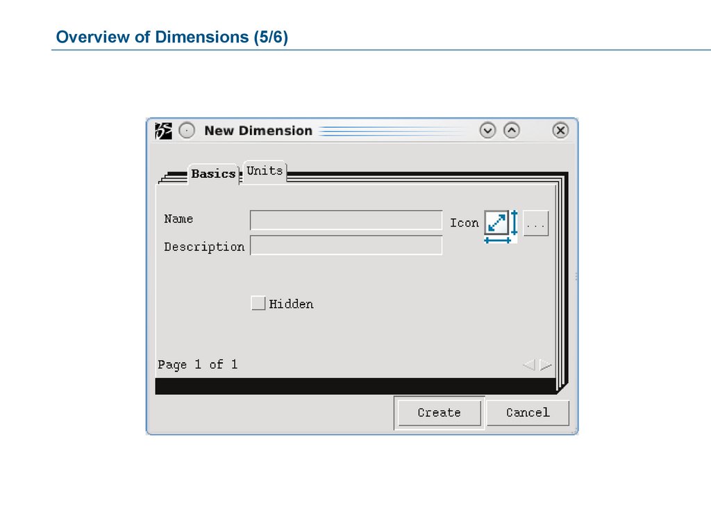
Overview of Dimensions (2/6)A Dimension is defined using the following pieces of information:
Name: Mandatory, up to 127 characters.
This is the name by which the Dimension will be identified.
Icon: For easy visual reference. The icon usually is an image that can be assigned to the Administrative
Object by importing it into the database.
Description: This appears as a roll-over text in a Dimension Chooser dialog box.
Hidden: Users cannot see the Dimension in a Dimension chooser list. Hidden Dimensions can, however, be
accessed by typing the name alphanumerically, if an appropriate dialog box is displayed to the user.
77.
Overview of Dimensions (3/6)For each Dimension, any number of Units can be defined. For example, when defining a Length Dimension, you
may want to define Units of Meter, Centimeter, Millimeter, etc.
For each Unit to be defined, the following values can be entered:
Name: The name of the Unit can be up to 127 characters. It is recommended to use the minimal number of
characters possible for ease of unit display. For example, the Name “F” corresponds to the Label Fahrenheit.
Label: It must contain the full name of the unit. For example, Fahrenheit or descriptive information about the
Name that must be up to 255 characters.
Multiplier: For the Default Unit the Multiplier “1” is used. For every other unit the Multiplier states the factor by
which the unit must be multiplied in order to account for the default unit. (Or the divisor by which the default
unit must be divided.)
Example:
Default unit is m, Multiplier 1.
Second unit is mm, Multiplier is 0.001
specified default unit 3.45: 3.45m / 0.001 = 3450mm
normalized value = unit value * multiplier + offset
Offset: 0 for the Default Unit; as required for others.
When defining the Default Unit, select the Default check box.
78.
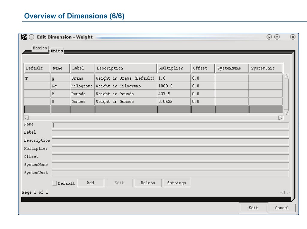
Overview of Dimensions (4/6)SystemName: This is the name of the System associated with the Unit, such as English or Metric.
SystemUnit: These are the Units to convert into when the defined SystemName is specified (for example, if
converting into Metric, the Units could be cm, mm or m).
Settings (obsolete): These are the name-value pairs of information used to send instructions to any target
page in an Href for the column in the displayed table.
79.
Overview of Dimensions (5/6)80.
Overview of Dimensions (6/6)81.
Overview of Attributes (1/16)Attributes are additional descriptive pieces of information that are not found within the Business Object’s basic
description.
They are used to define specific characteristics of a Business Object, which differentiate the Business Object
from the other Business Objects of the same Type.
82.
Overview of Attributes (2/16)An Attribute is defined using the following pieces of information:
Name: Mandatory, must be up to 127 characters.
This is the name by which the Attribute will be identified.
Icon: For easy visual reference.
Description: This appears as a roll-over text in an Attribute Chooser dialog box.
Type of Attribute: (cannot be changed after creation)
Boolean: Possible values are TRUE or FALSE (further values are not accepted).
Date/Time: To enter a date as a value Attribute using one of the allowed formats.
Integer: Whole numbers. Attributes of type Integer allow arithmetic calculations.
Real: Decimal numbers. Attributes of type Real allow arithmetic calculations.
String: Text with any type of characters (numbers, letters or any special symbols). Examples are
materials, colors, etc.
Scope and Owner (obsolete): The Scope options allow you to specify the scope of the new attribute.
Selecting Global creates an attribute that applies to all types, relationships, and interfaces. Selecting any of
the other three options creates an attribute that applies only to a specific type, relationship, or interface,
respectively. It also activates the Owner field in which you can enter the desired attribute owner.
83.
Overview of Attributes (3/16)An Attribute additionally has the following options:
Default: May or may not be defined in the range values.
Hidden: To not display this attribute in the 3DEXPERIENCE Open Matrix Navigator.
Multiline: The user may specify as many lines as necessary to adequately define the value.
Dimension: Choose the Dimension object to be associated with this attribute.
Maximum Length: Attributes defined as type String can also contain a maximum length definition (0 =
unlimited).
Reset on Clone: Attribute will be reset to its default value as a result of a Business Object Clone operation.
Reset on Revision: Attribute will be reset to its default value as a result of a Business Object Revision
operation.
Value Type: The Value Type options allow you to specify the attribute as being single-value, multi-value, or
range-value.
The Attribute must have a default value for the “Reset on” functionality to work.
84.
Overview of Attributes (4/16)For every Attribute, the Business Administrator will define values and/or ranges of values that can be made
mandatory for the end user, i.e. the value specified by the user must be contained in the defined ranges.
The following operators are available when defining static range values:
Operators for integer, real and date\time:
between: The value must be between the defined minimum and maximum value ranges –
optionally including or excluding those values.
equal: The Attribute value must be equal to this value. This is generally used when several
ranges are defined.
not equal: The Attribute value must not match this range value (unless equal to the default).
Greater Than >
Less Than <
Greater Than Equal >=
Less Than Equal <=
85.
Overview of Attributes (5/16)Operators for string type Attributes, which must be used when you use patterns to define a range:
Match Case: Specifies that the character string must match the exact case pattern value given
(case sensitive)
Not Match Case: Specifies that the character string must not match the exact case pattern value
(case sensitive)
Match: Specifies that the character string must match the exact pattern value given (case
insensitive)
Not Match: Specifies that the character string must not match the exact pattern value (case
insensitive)
86.
Overview of Attributes (6/16)In addition to define static range values for Attributes, dynamic range values can be defined using the
Program Range option.
This allows the execution of a Program to determine a value or list of values for the user to choose from. The
values could be based on current definitions in your system or could be read from files, etc.
For example:
You want a list of all Source Companies to be displayed whenever a user opens the Attribute Source of a
Business Object. The Source Companies are stored in your system as Business Objects of Type Source
Company with the Company name as the Business Object name.
This means you would have a Program defined as your Program Range Program, which reads all the names
of the Business Objects of Type Source Company and offers all these names as possible values to the user.
This allows for dynamic (as opposed to static) storage of Source Companies directly within the database,
eliminating the need for external referencing or verification.
87.
Overview of Attributes (7/16)You can specify more than one range.
For example, if you want to define an alphabetic range that excludes the letters I and O. This can be
accomplished as follows:
Between: A inclusive Z inclusive
Not Equal: I
Not Equal: O
88.
Overview of Attributes (8/16)Triggers are Programs that are run upon a certain event. The event is an action of the user or an automatic
action in the system, e.g. the promotion of a Business Object into the next state.
These events are predefined within the system and cover all possible actions on an object.
The available events are specific to the individual Administrative Objects.
For example:
The modification of an attribute value is an event on both the Attribute and the Business Object it
belongs to.
The creation of a Business Object is an event on the object’s Type.
The modification of an Attribute value on a Relationship is an event on both the Attribute and the
Relationship it belongs to.
89.
Overview of Attributes (9/16)Within every event there is the possibility of three separate program executions.
They are:
Check (Program is run before the event)
Override (Program is run in place of the event)
Action (Program is run after the event)
Available Trigger events for Attributes:
Modify
90.
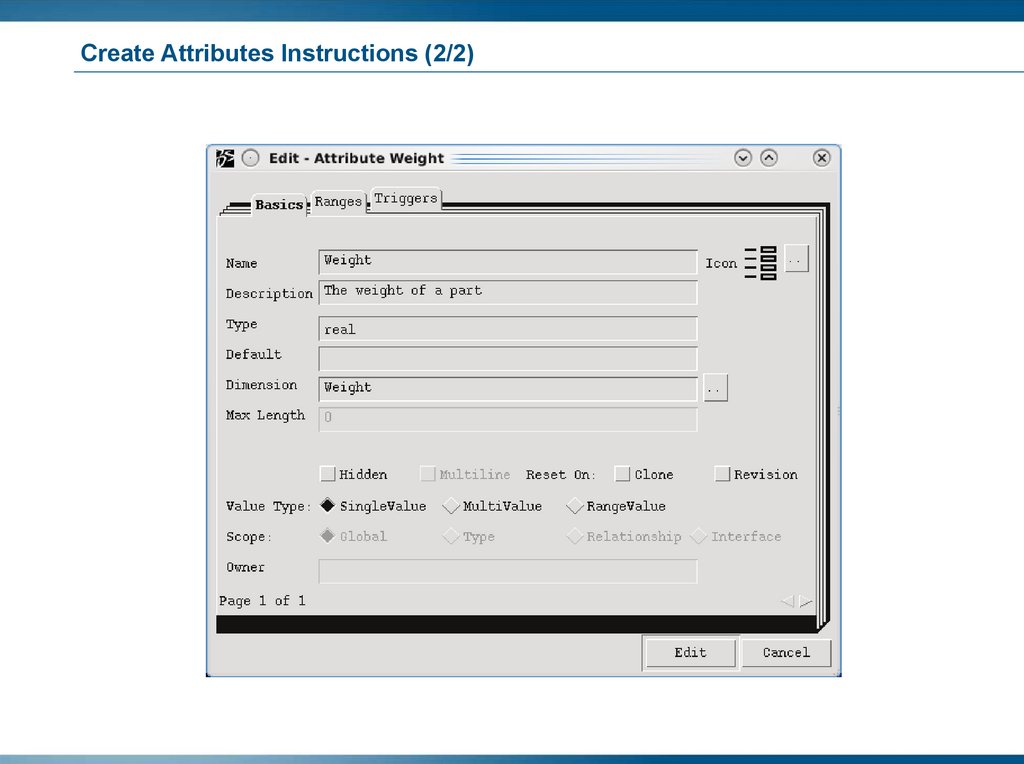
Overview of Attributes (10/16)Using the dialog box shown below, you can define the basic definitions for an Attribute.
91.
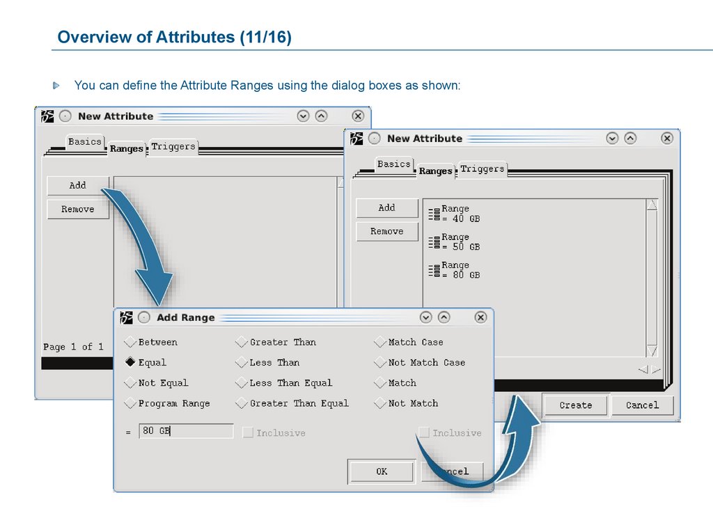
Overview of Attributes (11/16)You can define the Attribute Ranges using the dialog boxes as shown:
92.
Overview of Attributes (12/16)If you want to use a Program that gives the user a list of value options to choose from, specify an existing
Program Object.
93.
Overview of Attributes (13/16)Multi-Value Attributes
Traditionally, an attribute can specify only one value. However, in some cases it may be necessary for an
attribute to have multiple values, which could be stored as comma-separated values.
This would require additional logic in the form of a workaround in order to parse the comma-separated values
and display them properly.
However, this could in turn lead to issues when searching or indexing the data, as the kernel might not be
aware of the workaround convention.
To deal with these issues, 3DEXPERIENCE Platform provides the following support for multi-value attributes:
Multi-value attributes can be applied to any attribute type, including date, integer, real, boolean, and
string.
Multi-value attributes can define an order. An order number is used to display the attribute values in a
specific order.
Dimension can be applied to the numeric fields.
Each value can have its own unit of measure when Unit Of Measure (UOM) if applicable.
Searching is performed against each value separately to determine a match.
A multi-value attribute can have more than one instance of the same value.
94.
Overview of Attributes (14/16)Range-Value Attributes:
While multi-value attributes allow you to enter distinct values, range-value attributes allow you to enter
maximum and minimum values (for example, to model a range of 100%-20%).
This capability is enabled for numeric fields as well as dates (for example, to model a start and end date).
3DEXPERIENCE Platform provides the following support for range-value attributes:
Dimension can also be applied to the numeric fields.
The range can have only one UOM value.
Searching is performed against both values.
When setting values for a range-value attribute, you can specify either endpoint as inclusive (by default),
exclusive (using the keywords minexclude and maxeclude in MQL), or open-ended (if no value is
specified).
95.
Overview of Attributes (15/16)When you click Add in the Triggers tab, a dialog box is displayed as shown:
96.
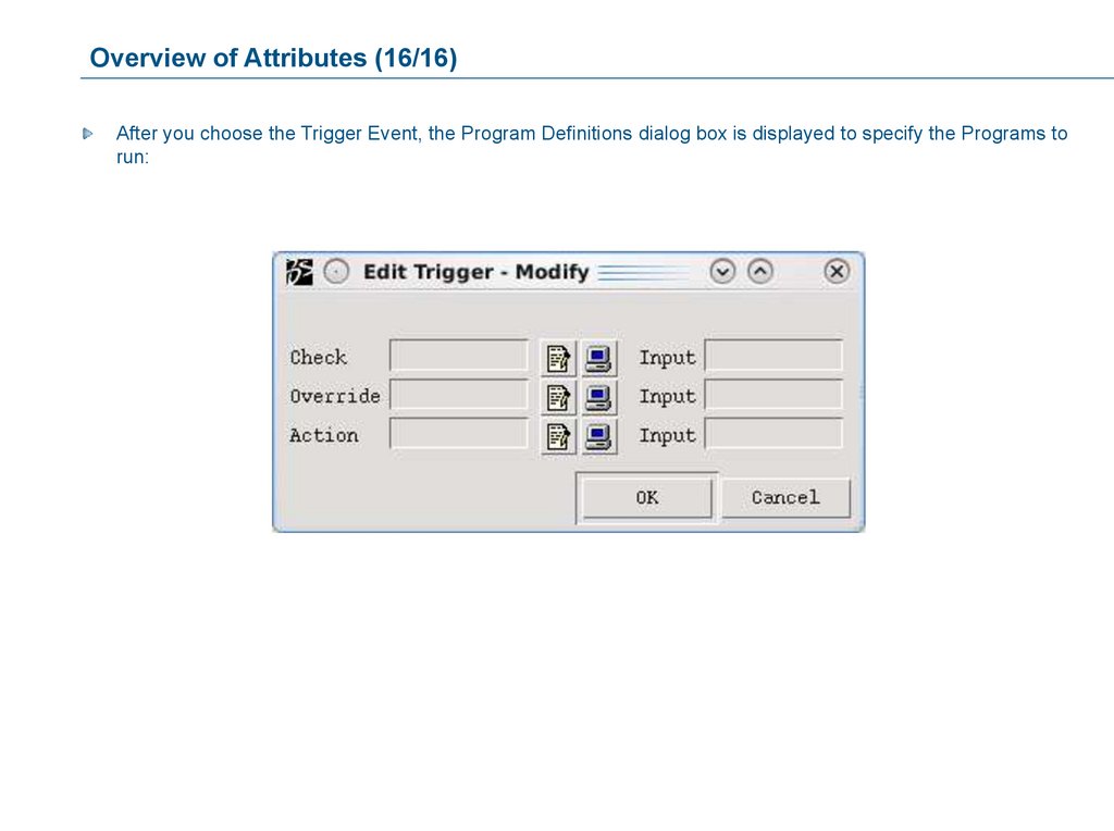
Overview of Attributes (16/16)After you choose the Trigger Event, the Program Definitions dialog box is displayed to specify the Programs to
run:
97.
Customizing Attributes via Model Specialization Management (1/3)2
1
Add an attribute
3
4
98.
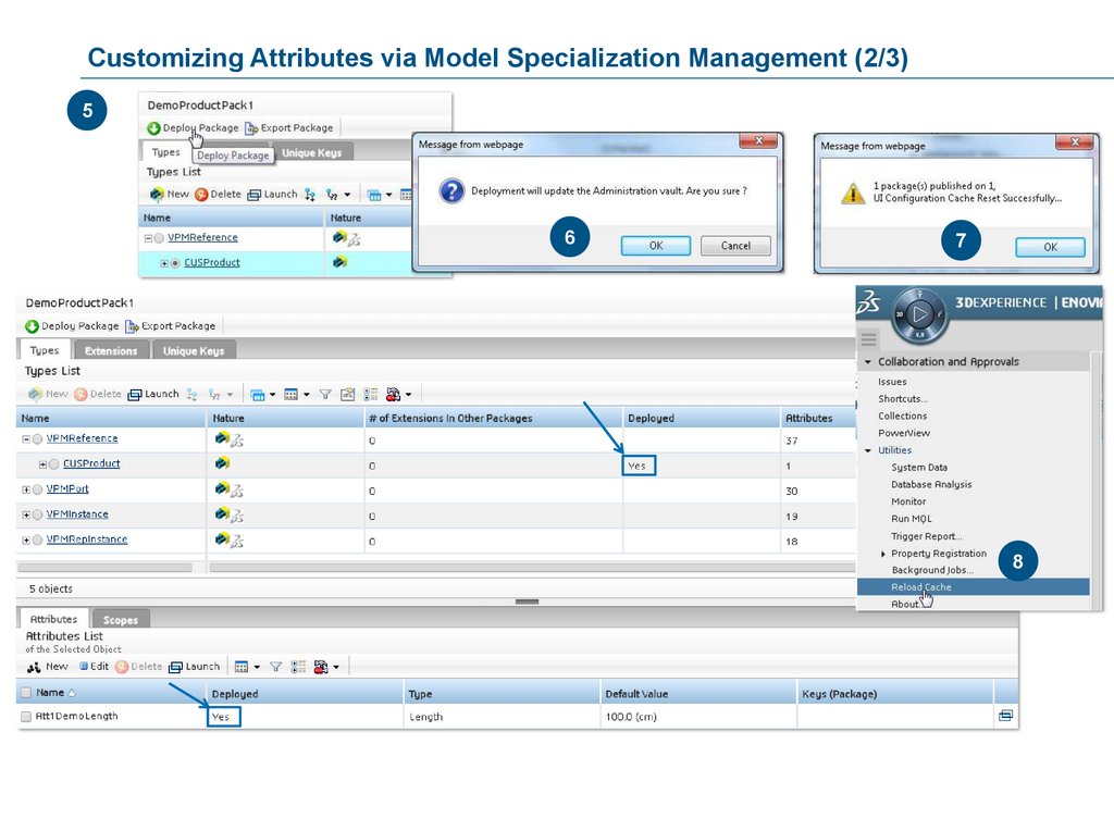
Customizing Attributes via Model Specialization Management (2/3)5
6
7
8
99.
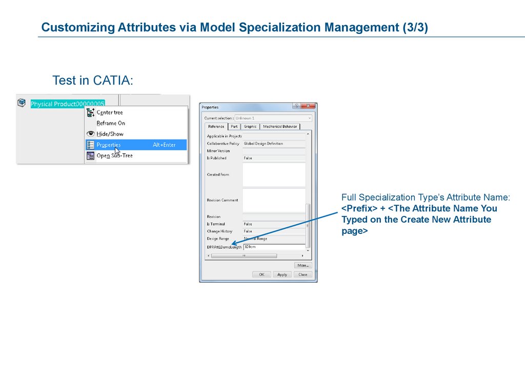
Customizing Attributes via Model Specialization Management (3/3)Test in CATIA:
Full Specialization Type’s Attribute Name:
<Prefix> + <The Attribute Name You
Typed on the Create New Attribute
page>
100.
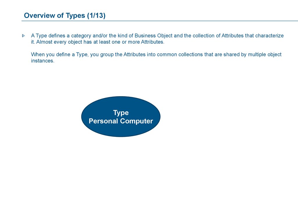
Overview of Types (1/13)A Type defines a category and/or the kind of Business Object and the collection of Attributes that characterize
it. Almost every object has at least one or more Attributes.
When you define a Type, you group the Attributes into common collections that are shared by multiple object
instances.
Type
Personal Computer
101.
Overview of Types (2/13)A Type is defined using the following pieces of information:
Name: Mandatory, must be up to 127 characters.
This is the name by which the Type will be identified.
Icon: For easy visual reference.
Description: This appears as a roll-over text in a Type Chooser dialog box.
Derived from: Selects the parent Type (parent can be an Abstract Type or not).
Abstract: Specifies if the Type is an Abstract Type or not. Abstract Types cannot be instantiated.
Hidden: Users cannot see the Type in a Type Chooser dialog box. Hidden Types can, however, be accessed
by typing the name alphanumerically, if an appropriate dialog box is displayed to the user.
102.
Overview of Types (3/13)Abstract Types cannot be instantiated, that is, you cannot create a Business Object from an Abstract Type.
Abstract Types typically serve as organizational Types.
For example, to categorize certain kinds of Types, such as DOCUMENT or PART.
A Type named DOCUMENT may serve to organize all your different documents and to inherit the
Attributes that all Objects of Type DOCUMENT should have, but at the same time may be too general to
create a Business Object of that Type.
103.
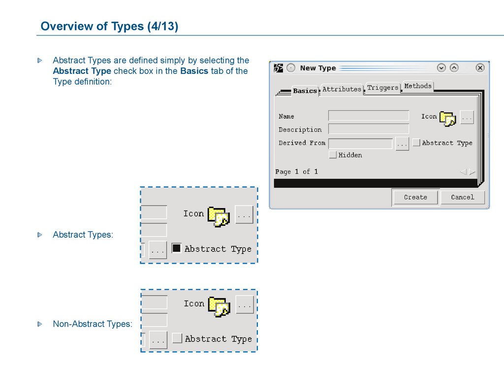
Overview of Types (4/13)Abstract Types are defined simply by selecting the
Abstract Type check box in the Basics tab of the
Type definition:
Abstract Types:
Non-Abstract Types:
104.
Overview of Types (5/13)Types use information from the following categories:
Attributes: Selects the Attributes for this Type. If the Type is a derived Type, the Attributes of the Parent Type
are assigned already.
Methods (obsolete): Program Objects that are assigned to a Type, allowing the user to manually execute the
program.
Triggers: Event-driven automated functionality existing as Program Objects defined within that Event.
105.
Overview of Types (6/13)Derived Types are the object Types that are derived from another object Type.
Every Type can have a parent Type.
The child Type is referred to as the Derived Type.
The parent Type can be an Abstract Type or a Non-Abstract Type.
The following elements are inherited from the parent: *
Attributes
Relationships
Policies
Methods
Triggers
* Inherited elements cannot be deleted from a Child Type that was derived from a Parent Type.
106.
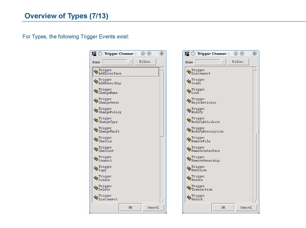
Overview of Types (7/13)For Types, the following Trigger Events exist:
107.
Overview of Types (8/13)Abstract: TRUE
Parent Type
PART
Attribute 1 Cost
Attribute 2 Source
Attribute 3 Weight
Abstract: FALSE
System Box
is derived from Type PART.
Derived Type
System Box
Attributes 1, 2 and 3 are inherited from the
parent Type.
Attribute 1 Cost inherited
Attribute 2 Source inherited
Attribute 3 Weight inherited
Additional Attributes can be assigned
explicitly to every Type.
Attribute 4 CPU Speed added
Attribute 5 CPU Model added
108.
Overview of Types (9/13)The following naming conventions are recommended:
Use full names for your Types for easier identification.
Do not use special characters.
There is a 255 character string limitation on names.
It is a recommended convention to fully capitalize the names of Abstract Types in order to be able to recognize
an Abstract Type immediately, for example: PART (Abstract) as opposed to System Box Part (non-Abstract).
Use a meaningful description.
109.
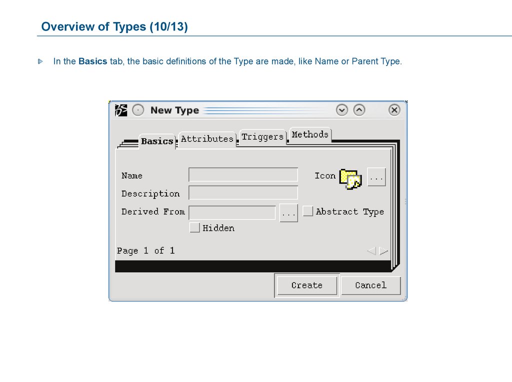
Overview of Types (10/13)In the Basics tab, the basic definitions of the Type are made, like Name or Parent Type.
110.
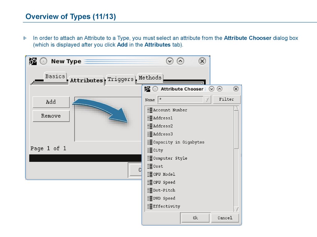
Overview of Types (11/13)In order to attach an Attribute to a Type, you must select an attribute from the Attribute Chooser dialog box
(which is displayed after you click Add in the Attributes tab).
111.
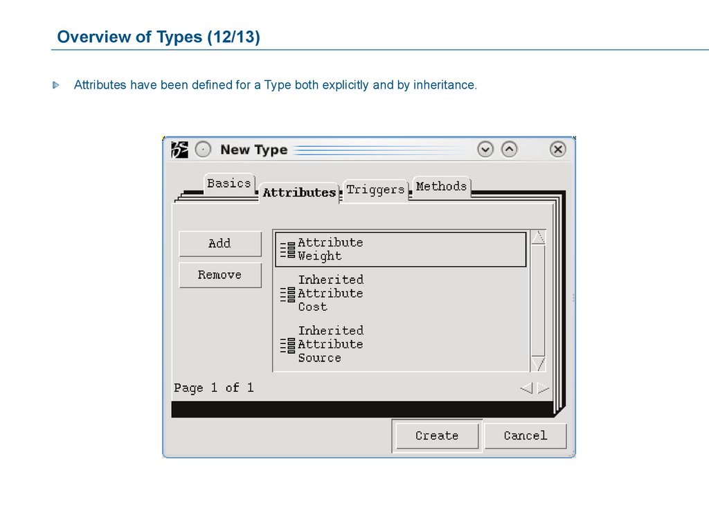
Overview of Types (12/13)Attributes have been defined for a Type both explicitly and by inheritance.
112.
Overview of Types (13/13)In order to attach a Trigger to a Type, you must choose the Trigger chosen in the Trigger Chooser dialog box
(which is displayed after you click Add in the Triggers tab).
113.
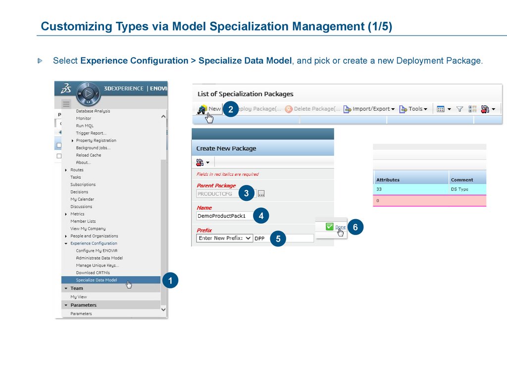
Customizing Types via Model Specialization Management (1/5)Select Experience Configuration > Specialize Data Model, and pick or create a new Deployment Package.
2
3
4
6
5
1
114.
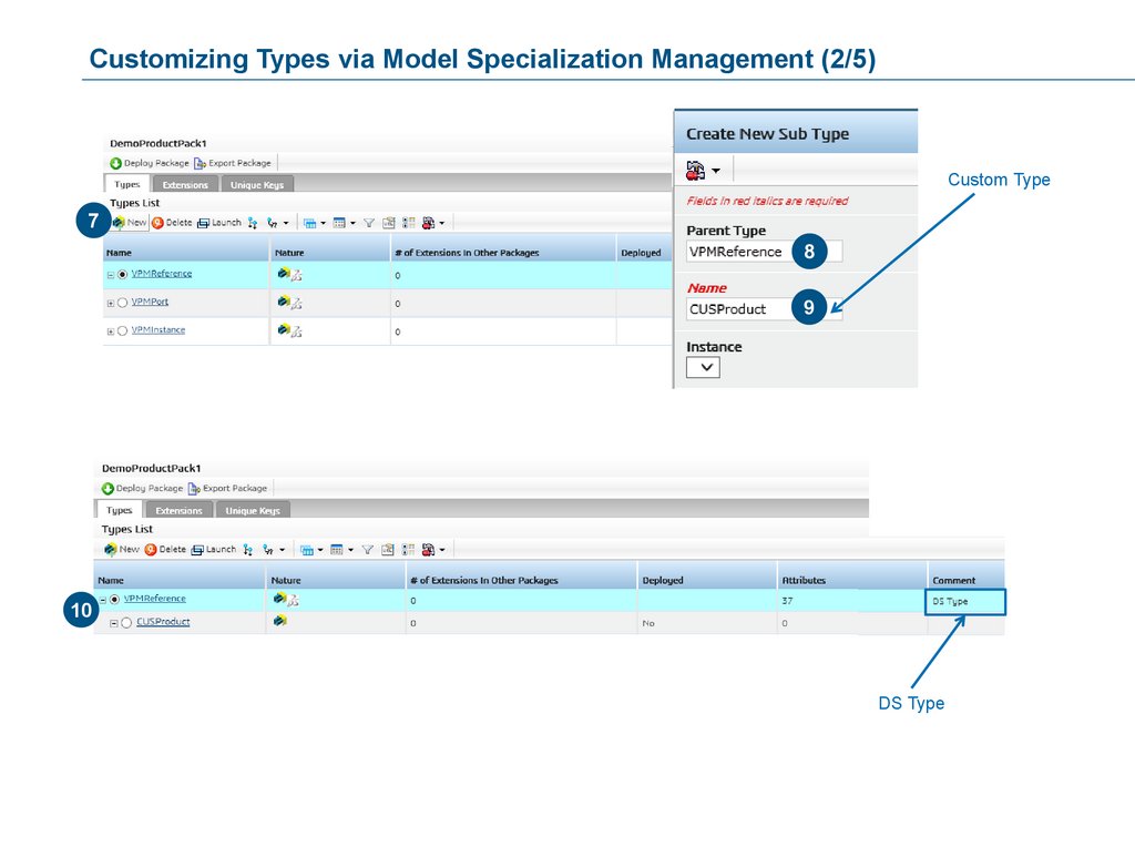
Customizing Types via Model Specialization Management (2/5)Custom Type
7
8
9
10
DS Type
115.
Customizing Types via Model Specialization Management (3/5)11
12
13
14
116.
Customizing Types via Model Specialization Management (4/5)Test in the 3DEXPERIENCE Engineering App:
117.
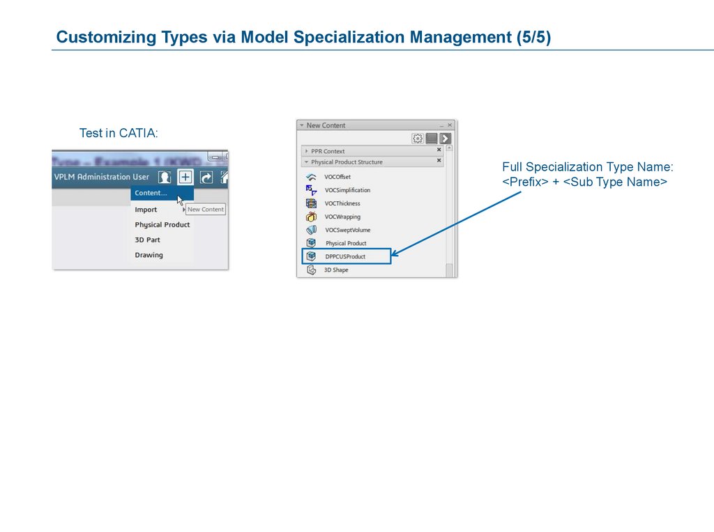
Customizing Types via Model Specialization Management (5/5)Test in CATIA:
Full Specialization Type Name:
<Prefix> + <Sub Type Name>
118.
Case Study: Creating Dimensions Attributes and TypesPlease read through the Case Study and follow the Exercise Instructions:
1. Please follow the instructions in the correct order.
2. Use the object names given in the Exercises.
(MQL scripts which we are going to use during the course of the class will refer to these objects names).
30 minutes
119.
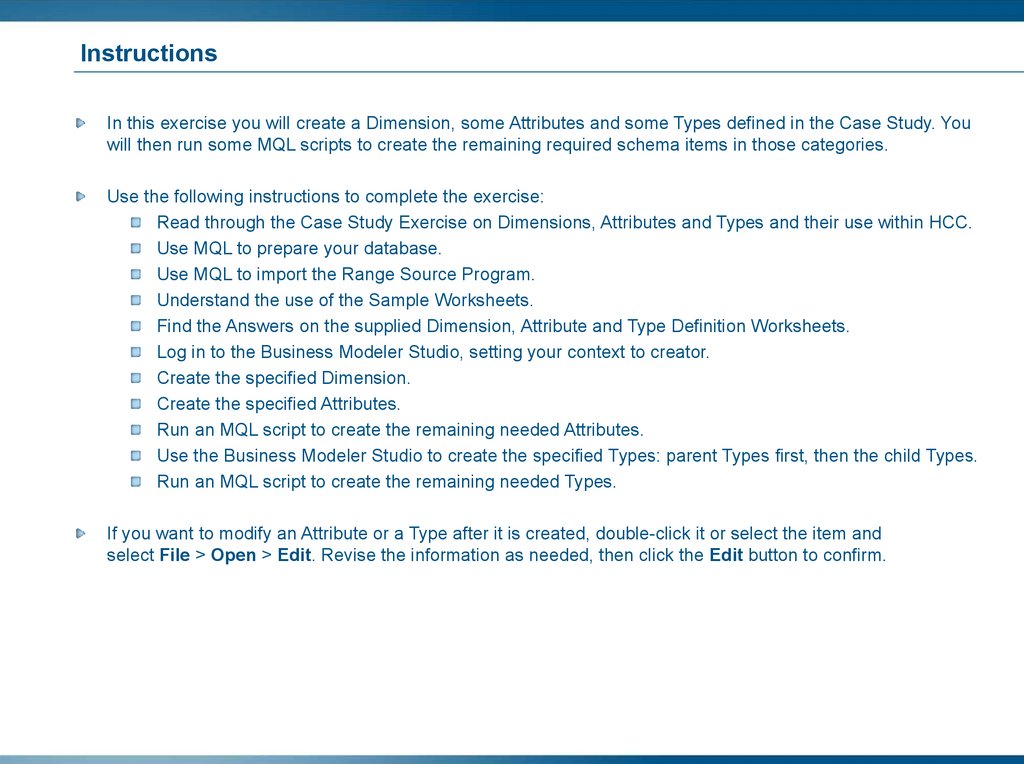
InstructionsIn this exercise you will create a Dimension, some Attributes and some Types defined in the Case Study. You
will then run some MQL scripts to create the remaining required schema items in those categories.
Use the following instructions to complete the exercise:
Read through the Case Study Exercise on Dimensions, Attributes and Types and their use within HCC.
Use MQL to prepare your database.
Use MQL to import the Range Source Program.
Understand the use of the Sample Worksheets.
Find the Answers on the supplied Dimension, Attribute and Type Definition Worksheets.
Log in to the Business Modeler Studio, setting your context to creator.
Create the specified Dimension.
Create the specified Attributes.
Run an MQL script to create the remaining needed Attributes.
Use the Business Modeler Studio to create the specified Types: parent Types first, then the child Types.
Run an MQL script to create the remaining needed Types.
If you want to modify an Attribute or a Type after it is created, double-click it or select the item and
select File > Open > Edit. Revise the information as needed, then click the Edit button to confirm.
120.
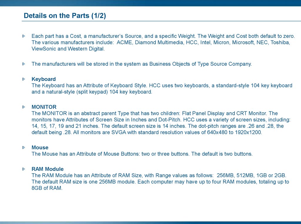
Details on the Parts (1/2)Each part has a Cost, a manufacturer’s Source, and a specific Weight. The Weight and Cost both default to zero.
The various manufacturers include: ACME, Diamond Multimedia, HCC, Intel, Micron, Microsoft, NEC, Toshiba,
ViewSonic and Western Digital.
The manufacturers will be stored in the system as Business Objects of Type Source Company.
Keyboard
The Keyboard has an Attribute of Keyboard Style. HCC uses two keyboards, a standard-style 104 key keyboard
and a natural-style (split keypad) 104 key keyboard.
MONITOR
The MONITOR is an abstract parent Type that has two children: Flat Panel Display and CRT Monitor. The
monitors have Attributes of Screen Size in Inches and Dot-Pitch. HCC uses a variety of screen sizes, including:
14, 15, 17, 19 and 21 inches. The default screen size is 14 inches. The dot-pitch ranges are .26 and .28, the
default being .28. All monitors are SVGA with standard resolution values of 640x480 to 1920x1200.
Mouse
The Mouse has an Attribute of Mouse Buttons: two or three buttons. The default is two buttons.
RAM Module
The RAM Module has an Attribute of RAM Size, with Range values as follows: 256MB, 512MB, 1GB or 2GB.
The default RAM size is one 256MB module. Each computer may have up to four RAM modules, totaling up to
8GB of RAM.
121.
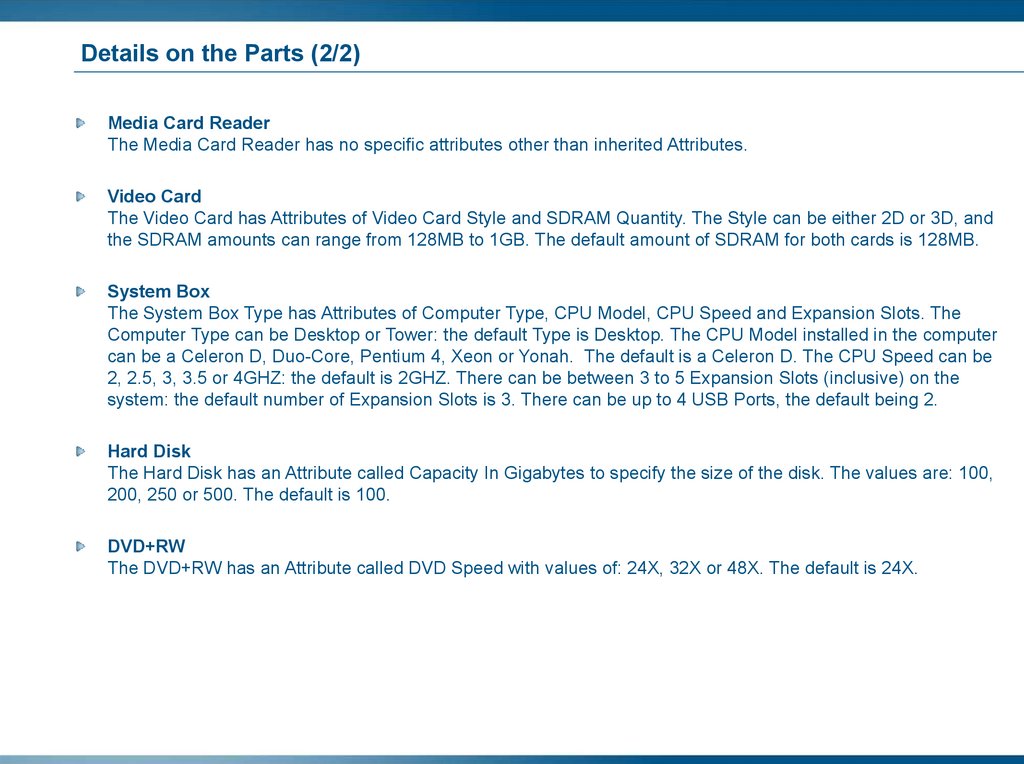
Details on the Parts (2/2)Media Card Reader
The Media Card Reader has no specific attributes other than inherited Attributes.
Video Card
The Video Card has Attributes of Video Card Style and SDRAM Quantity. The Style can be either 2D or 3D, and
the SDRAM amounts can range from 128MB to 1GB. The default amount of SDRAM for both cards is 128MB.
System Box
The System Box Type has Attributes of Computer Type, CPU Model, CPU Speed and Expansion Slots. The
Computer Type can be Desktop or Tower: the default Type is Desktop. The CPU Model installed in the computer
can be a Celeron D, Duo-Core, Pentium 4, Xeon or Yonah. The default is a Celeron D. The CPU Speed can be
2, 2.5, 3, 3.5 or 4GHZ: the default is 2GHZ. There can be between 3 to 5 Expansion Slots (inclusive) on the
system: the default number of Expansion Slots is 3. There can be up to 4 USB Ports, the default being 2.
Hard Disk
The Hard Disk has an Attribute called Capacity In Gigabytes to specify the size of the disk. The values are: 100,
200, 250 or 500. The default is 100.
DVD+RW
The DVD+RW has an Attribute called DVD Speed with values of: 24X, 32X or 48X. The default is 24X.
122.
Source CompanyThe Source Company Type is used to create the Source Company Business Objects that will be instantiated in
the database to represent the particular manufacturers that supply materials to HCC.
Attributes of the Source Company:
The Source Attribute, which is assigned to all PARTs, is a dynamic Attribute whose range values are not
explicitly defined by the Business Administrator during the Attribute’s creation.
Instead, the values displayed to the user for this Attribute are gathered by a Program that is called every time
the user opens the Attribute to modify that value. This Program reads the names of all Business Objects of the
Type “Source Company” and displays them to the user as selectable values of the Source Attribute.
As new Source Company business objects are added to the database, any subsequent modification of the
Source Attribute on any Business Object that uses it will display a list of the names of ALL “Source Company”
Business Objects that currently exist in the database.
123.
Use of Dimensions in the HCC SchemaHCC wants to display the weight of all PARTs in Grams (Primary Measurement Unit), Ounces, Pounds and
Kilograms. The Dimension that you will create in this exercise will allow this type of display within a Table. You
will build a Table for Dimension display later in this course.
The maximum room temperature to store the system box is defined to instruct the customers. For customers in
different countries the Room Temperature can be evaluated in Degree Celsius (Primary Measurement Unit)
and Fahrenheit.
124.
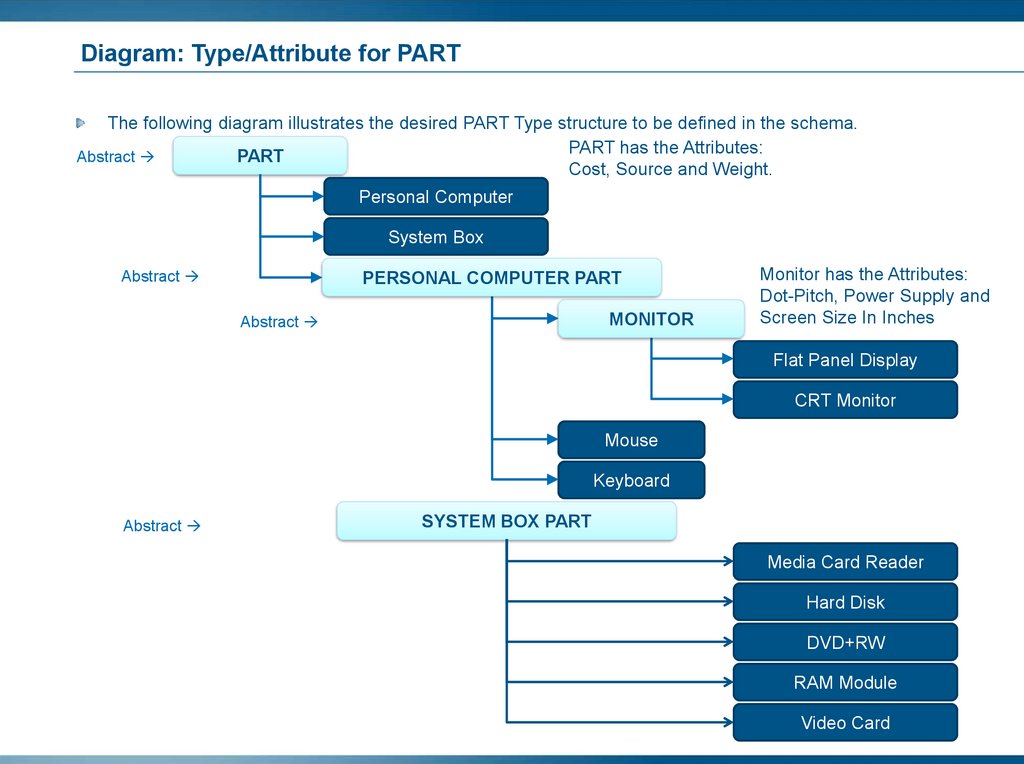
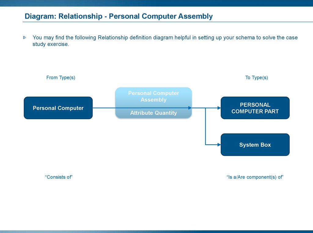
Diagram: Type/Attribute for PARTThe following diagram illustrates the desired PART Type structure to be defined in the schema.
PART has the Attributes:
PART
Abstract
Cost, Source and Weight.
Personal Computer
System Box
Abstract
PERSONAL COMPUTER PART
MONITOR
Abstract
Monitor has the Attributes:
Dot-Pitch, Power Supply and
Screen Size In Inches
Flat Panel Display
CRT Monitor
Mouse
Keyboard
Abstract
SYSTEM BOX PART
Media Card Reader
Hard Disk
DVD+RW
RAM Module
Video Card
125.
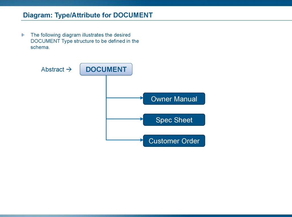
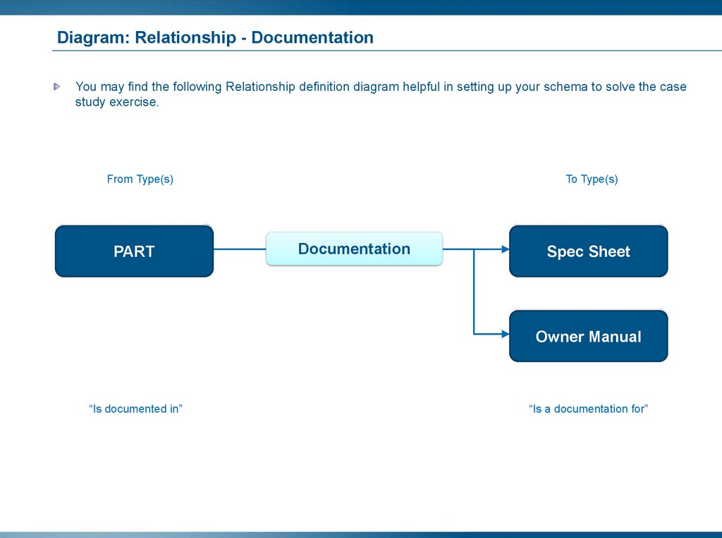
Diagram: Type/Attribute for DOCUMENTThe following diagram illustrates the desired
DOCUMENT Type structure to be defined in the
schema.
Abstract
DOCUMENT
Owner Manual
Spec Sheet
Customer Order
126.
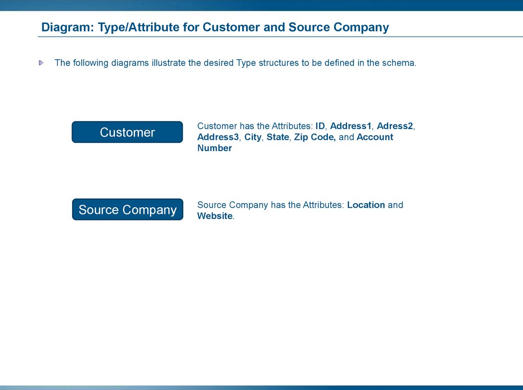
Diagram: Type/Attribute for Customer and Source CompanyThe following diagrams illustrate the desired Type structures to be defined in the schema.
Customer
Source Company
Customer has the Attributes: ID, Address1, Adress2,
Address3, City, State, Zip Code, and Account
Number
Source Company has the Attributes: Location and
Website.
127.
Prepare your DatabaseYou will now clear your database of all Business Objects and schema in preparation for the upcoming
exercises:
Start an MQL session:
Go to /home/data/RTV/enoviaV6R2015x/studio/scripts folder and use Tools -> Open Terminal.
In opened console windows type [./mql].
Type:
set context user creator;
clear all;
After the command is run, all the Business Objects and Schema in your database will have been deleted to
allow you to create your own definitions. Verify this by starting your Business Modeler and performing a Find
All schema.
You should have only the following persons:
creator and guest.
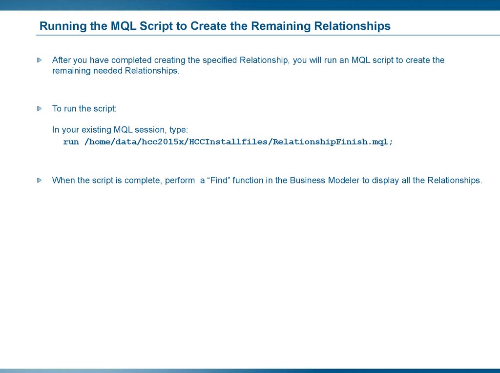
In your existing MQL session type:
run /home/data/hcc2015x/HCCInstallfiles/StoreVaultAll.mql;
Do not close the MQL session. You will be using it in the upcoming exercises.
128.
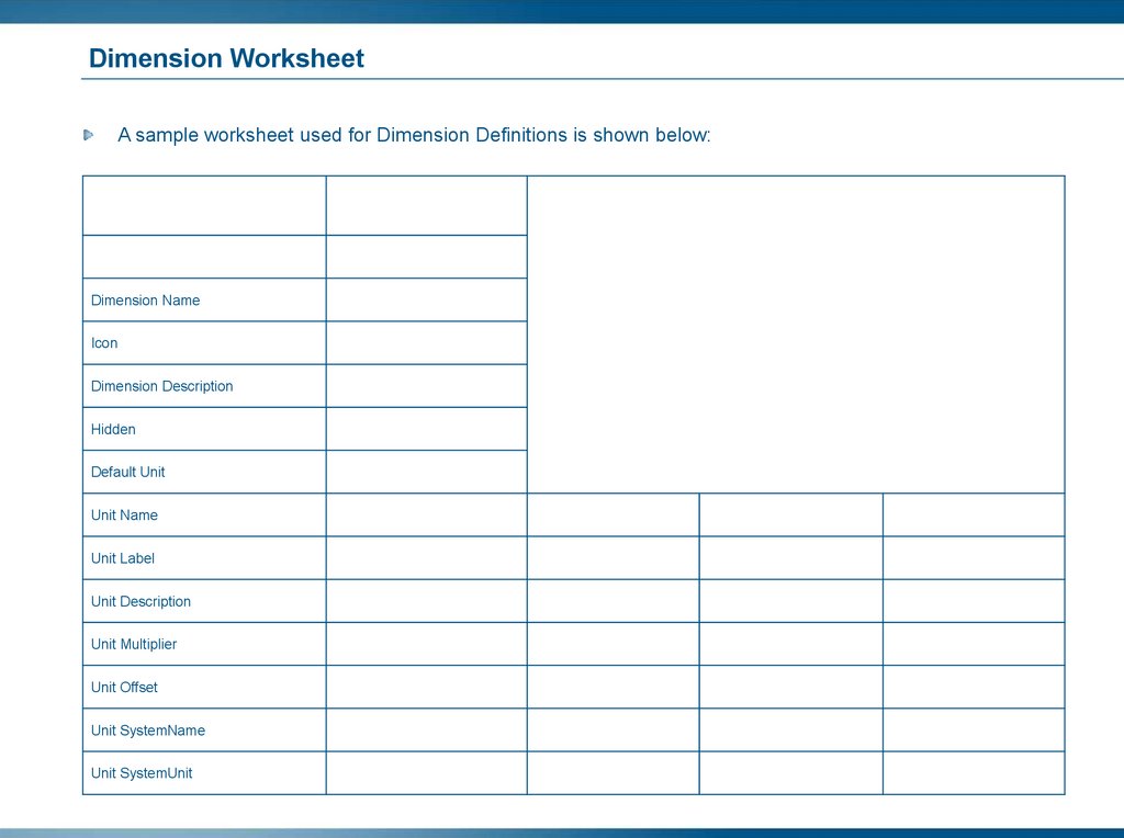
Dimension WorksheetA sample worksheet used for Dimension Definitions is shown below:
Dimension
Dimension Name
Icon
Dimension Description
Hidden
Default Unit
Unit Name
Unit Label
Unit Description
Unit Multiplier
Unit Offset
Unit SystemName
Unit SystemUnit
129.
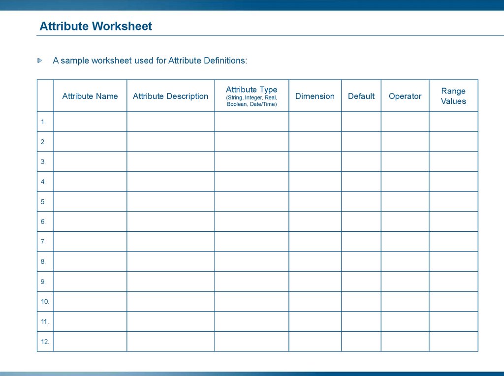
Attribute WorksheetA sample worksheet used for Attribute Definitions:
Attribute Name
1.
2.
3.
4.
5.
6.
7.
8.
9.
10.
11.
12.
Attribute Description
Attribute Type
(String, Integer, Real,
Boolean, Date/Time)
Dimension
Default
Operator
Range
Values
130.
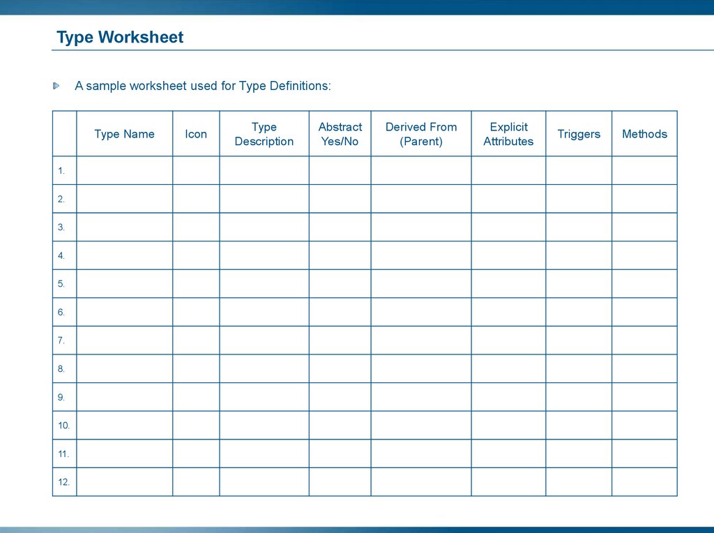
Type WorksheetA sample worksheet used for Type Definitions:
Type Name
1.
2.
3.
4.
5.
6.
7.
8.
9.
10.
11.
12.
Icon
Type
Description
Abstract
Yes/No
Derived From
(Parent)
Explicit
Attributes
Triggers
Methods
131.
Create Dimensions Instructions (1/2)Use the following completed worksheet to specify your Dimension definition.
Dimension
Dimension Name
Icon
Dimension Description
Hidden
Weight
N/A
Weight of the item
N/A
Default Unit
T
Unit Name
g
kg
lbs
oz
Unit Label
Grams
Kilograms
Pounds
Ounces
Weight in Grams
Weight in Kilograms
Weight in Pounds
Weight in Ounces
Unit Multiplier
1
1000.0
453.59237
28.349523125
Unit Offset
0
0
0
0
Unit Description
Unit SystemName
Unit SystemUnit
After you have completed creating the Weight Dimension, you will run an MQL script to create the remaining
Dimension Temperature.
To run the script:
In your existing MQL session:
a. Type: run /home/data/hcc2015x/HCCInstallfiles/DimensionFinish.mql;
b. When the script is complete, perform a “Find” functionality in the Business Modeler to display all the
Dimensions.
132.
Create Dimensions Instructions (2/2)133.
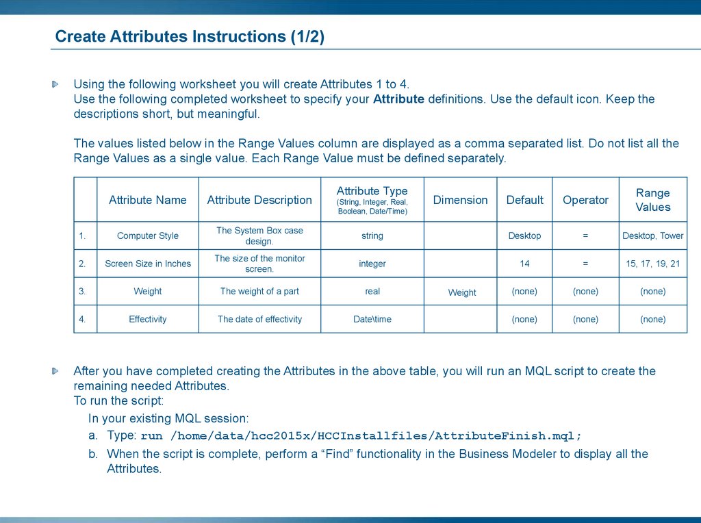
Create Attributes Instructions (1/2)Using the following worksheet you will create Attributes 1 to 4.
Use the following completed worksheet to specify your Attribute definitions. Use the default icon. Keep the
descriptions short, but meaningful.
The values listed below in the Range Values column are displayed as a comma separated list. Do not list all the
Range Values as a single value. Each Range Value must be defined separately.
Attribute Type
Default
Operator
Range
Values
string
Desktop
=
Desktop, Tower
The size of the monitor
screen.
integer
14
=
15, 17, 19, 21
Weight
The weight of a part
real
(none)
(none)
(none)
Effectivity
The date of effectivity
Date\time
(none)
(none)
(none)
Attribute Name
Attribute Description
1.
Computer Style
The System Box case
design.
2.
Screen Size in Inches
3.
4.
(String, Integer, Real,
Boolean, Date/Time)
Dimension
Weight
After you have completed creating the Attributes in the above table, you will run an MQL script to create the
remaining needed Attributes.
To run the script:
In your existing MQL session:
a. Type: run /home/data/hcc2015x/HCCInstallfiles/AttributeFinish.mql;
b. When the script is complete, perform a “Find” functionality in the Business Modeler to display all the
Attributes.
134.
Create Attributes Instructions (2/2)135.
Create Type Instructions (1/2)Using the following worksheet you will create Types 1 to 5.
Use the following completed worksheet to specify your Type definitions. Use either the default icon or the icons
available in the folder /home/data/hcc2015x/HCCgifs.
Do not select an icon for Type 1 as this is an Abstract Type and can never be instantiated.
Type Name
Icon
Type Description
Abstract
Yes/No
Derived From
(Parent)
Explicit
Attributes
1.
DOCUMENT
N/A
Documentation for the
computer
YES
N/A
Originator,
Effectivity
2.
Owner Manual
Owner
Manual.
gif
Owner guide for a
personal computer
No
DOCUMENT
N/A
3.
Spec Sheet
SpecShe
et.gif
Spec sheet for a part
No
DOCUMENT
N/A
4.
Customer Order
Custome
rOrder.gi
f
Customer order
information
No
DOCUMENT
N/A
5.
Source Company
Compan
y.gif
Company supplying the
Part
No
N/A
Location,
Website
Triggers
Methods
After you have completed creating the Types in the above table, you will run an MQL script to create the remaining
needed Types.
To run the script:
In your existing MQL session:
a. Type: run /home/data/hcc2015x/HCCInstallfiles/TypeFinish.mql;
b. When the script is complete, perform a ‘Find’ functionality in the Business Modeler to display all the Types.
136.
Create Type Instructions (2/2)137.
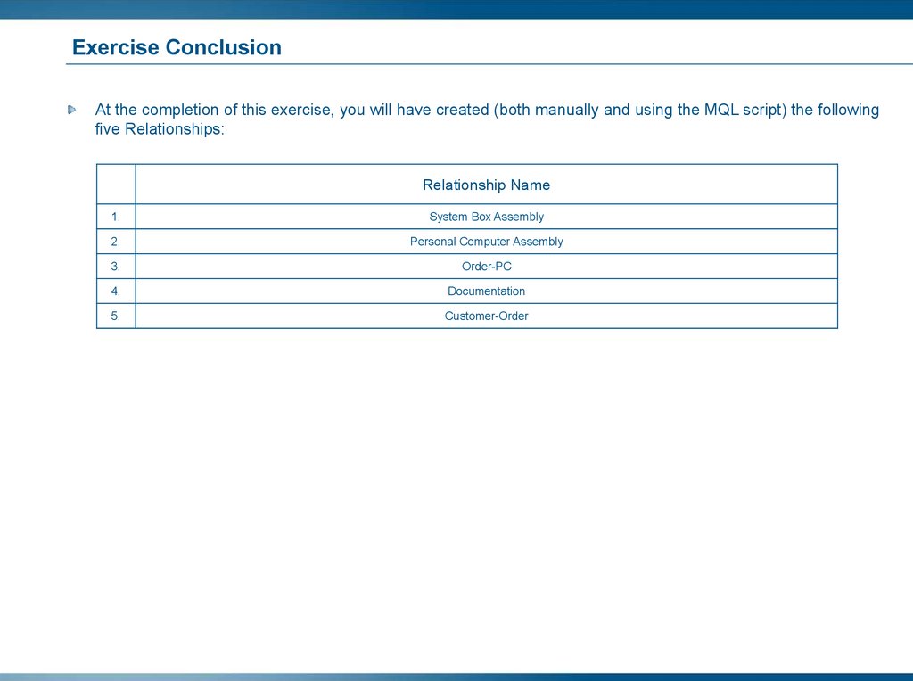
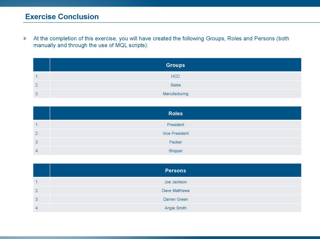
Exercise ConclusionAt the completion of this exercise, you will have created (both manually and through the use of MQL scripts) the
following Dimension, Attributes and Types:
Dimension Name
1.
Weight
2.
Temperature
Attribute Name
Attribute Name
Attribute Name
1.
Account Number
12.
Address1
23.
Address2
2.
Address3
13.
Capacity in Gigabytes
24.
City
3.
Computer Style
14
Cost
25.
CPU Model
4.
CPU Speed
15.
Dot-Pitch
26.
DVD Speed
5.
Effectivity
16.
Expansion Slots
27.
ID
6.
Keyboard Style
17.
Location
28.
Mouse Buttons
7.
OrderQty
18.
Originator
29.
Power Supply
8.
Quantity
19.
RAM Size
30
RAM Type
9.
Screen Size in Inches
20.
SDRAM Quantity
31.
Source
10.
State
21.
Video Card Style
32.
Website
11.
Weight
22.
Zip Code
33.
Temperature
Type Name
Type Name
Type Name
1.
CRT Monitor
8.
Keyboard
15.
PERSONAL COMPUTER PART
2.
Customer
9.
Media Card Reader
16.
RAM
3.
Customer Order
10.
MONITOR
17.
Source Company
4.
DOCUMENT
11.
Mouse
18.
Spec Sheet
5.
DVD+RW
12.
Owner Manual
19.
System Box
6.
Flat Panel Display
13.
PART
20.
SYSTEM BOX PART
7.
Hard Disk
14
Personal Computer
21.
Video Card
138.
SummaryDimensions, Attributes and Types
Attributes are the additional pieces of descriptive
information used to specify the values associated
with a Business Object or a Relationship.
Attributes are (optionally) assigned to Types in the
schema by the Business Administrator.
Any defined Attribute in the 3DEXPERIENCE
Platform database can be assigned to a Type.
A Type defines a category and/or the kind of
Business Object and the collection of Attributes that
characterize it. Almost every object has at least one
or more Attributes.
139.
RelationshipsYou will learn about the components of a
Relationship. You will also create Relationships as
Administrative Objects for your data model.
Here are the topics to be covered:
1. The Concepts of 3DEXPERIENCE
Platform Schema
2. Case Study Overview
3. Dimensions, Attributes and Types
4. Relationships
5. Programs
6. Persons, Groups, Roles and
Associations
7. Files and Formats
8. Policies
9. Rules
140.
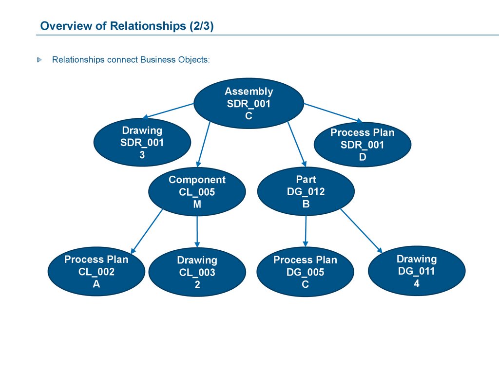
Overview of Relationships (1/3)Relationships are used to connect Business Objects into structures, for example, as in a Bill of Materials.
They define the rules for Business Object connectivity, as well as what should happen to any connections
during a Revise or a Clone operation.
Relationships also permit connecting a Business Object to another Relationship. This functionality is referred
to as Rel-to-Rel. It offers, for example, the ability to allow another object to act as a substitute for one of the
objects or to allow the connected object to act as common information between both objects.
Relationships support inheritance, this means a Relationship can be derived from another Relationship. When
this occurs, the child relationship will inherit the attributes and triggers from its parent.
Relationships can also be declared as abstract. Business objects cannot be connected with abstract
relationships. The abstract relationship can be used as parent in an inheritance hierarchy.
141.
Overview of Relationships (2/3)Relationships connect Business Objects:
Assembly
SDR_001
C
Drawing
SDR_001
3
Process Plan
CL_002
A
Process Plan
SDR_001
D
Component
CL_005
M
Part
DG_012
B
Drawing
CL_003
2
Process Plan
DG_005
C
Drawing
DG_011
4
142.
Overview of Relationships (3/3)All Relationships always have a From end and a To end, with the arrow always on the To end.
All Relationships exist between two Business Objects or a Business Object and a Relationship: one on the
From end and one on the To end.
The Types/Relationships on the From end can be same as or different from the Types/Relationships on the To
end.
Attributes can be assigned to Relationships.
143.
MeaningEach side of the Relationship can have a text meaning associated with it to define how the connecting end
relates to the other end, and to help the user to identify the purpose for connecting the objects/relationships.
It is recommended that a meaning be defined for each end.
Assembly
NGT_367_A
1
From side
From side Meaning:
“Consists of ”
Assembly
Part
SD_288_A
4
Relationship Name
To side
To side Meaning:
“Is part of”
144.
Business Object ConnectionsSeveral Business Objects of the same Type can be connected to one single object using the same type of
Relationship.
Assembly
Assembly
PLT_482_B
3
Assembly
Part
DF_288_B
2
Part
ST_29_C
3
145.
Equivalent RelationshipsAn equivalent Relationship helps the Business Objects of the same Type to be connected.
This means that the same Type is specified in both the From and To side of the relationship definition.
The direction of the relationship is determined by the selection of the From object.
Part
SD_354_A
1
Part
SD_355_A
1
Alternate Part
Part
CK_232_B
2
Alternate Part
Part
CK_232_B
3
146.
Hierarchical Relationships (1/3)A Hierarchical Relationship helps to identify the difference between the Types defined on the From side and
the Types defined on the To side.
Assembly
From side
Assembly
Part
To side
147.
Hierarchical Relationships (2/3)A Hierarchical Relationship can have one Type defined on the From side and multiple different and/or same
Types on the To side.
Assembly
Assembly
Part
Assembly
Assembly
Assembly
Component
148.
Hierarchical Relationships (3/3)A Hierarchical Relationship can have multiple different and/or same Types on the From side and one Type (an
Abstract, for example) on the To side.
Part
Documentation
Sub-Assembly
Documentation
Spec Sheet
Component
Documentation
149.
Cardinality (1/4)Cardinality defines the number of connections of a specific Relationship that a Business Object may have.
The cardinality options for the relationship are:
One to One
One to Many, or Many to One
Many to Many
150.
Cardinality (2/4)Relationships: Cardinality – One to One
A specific Business Object can be connected only once to another specific Business Object using this
Relationship.
PC – System Box
Personal Computer
Metro0001
A
X
System Box
Metro0001
A
PC – System Box
System Box
Metro0003
A
151.
Cardinality (3/4)Relationships: Cardinality – Many to One
Many Business Objects can be connected to One Business Object using this Relationship.
Customer Order
Metro0001
A
Customer Order
UniCap0023
A
Customer Order
Oktalon0003
A
Customer Order
NefCo0014
A
Order
Order
Personal Computer
XTR-4
A
Order
Order
X
X
Personal Computer
XTC-5
D
152.
Cardinality (4/4)Relationships: Cardinality – Many to Many
When using a Relationship with a cardinality of Many-to-Many, connections can exist from multiple Business
Objects/Relationships to multiple Business Objects/Relationships.
Mouse
MS 3 Button
A
Personal Computer
Metro0001
A
PC – PC Part
Personal Computer
Metro0002
B
Flat Panel Display
ViewSonic 19C
C
Keyboard
ACME 104 Key
A
System Box
XTR-P
A
153.
Revision Rules (1/8)When two Business Objects are connected, and one (or both) of the objects is (are) revised, Revision Rules
will specify what will happen with regard to the connection.
Revision Rules are specified for both sides of the relationship:
For the revision of the object on the From side
For the Revision of the object on the To side
154.
Revision Rules (2/8)Revision Rules: Options
None: The Relationship remains where it is. The new revision of the object does not have the original
Relationship.
Float: The Relationship floats to the new revision of the object. The original object loses the Relationship.
Replicate: The Relationship to the original object remains where it is and the connection is replicated to the
new revision of the object.
155.
Revision Rules (3/8)Revision Rules: None
Before Revision:
Object A
Original
Object B
156.
Revision Rules (4/8)Revision Rules: None
After Revision:
Object A
Original
Object B
Object A
REVISION
The new revision of
the object does not
have a connection.
157.
Revision Rules (5/8)Revision Rules: Float
Before Revision:
Object A
Original
Object B
158.
Revision Rules (6/8)Revision Rules: Float
After Revision:
Object A
Original
Object B
Object A
REVISION
The connections floats
to the new revision of
the object.
159.
Revision Rules (7/8)Revision Rules: Replicate
Before Revision:
Object A
Original
Object B
160.
Revision Rules (8/8)Revision Rules: Replicate
After Revision:
Object A
Original
Object B
Object A
REVISION
The connection is
replicated to the new
revision of the object.
The Replicate revision rule requires that the cardinality should be Many on the side that is revised,
as there will be more than one connection on the Many side as a result of the revision.
161.
Cloning RulesLike in Revising an object, there is an option to specify the Relationship’s behavior when Cloning an object.
The Cloning Rules offer the same functionality as the Revision Rules:
None: The new clone of the object will not have the connections.
Float: The connection floats to the new clone of the object.
Replicate: The connection to the old object remains and the connection is replicated to the new clone of
the object.
162.
Connecting Object CategoriesTo more easily define which Types are to be used in a relationship definition, you can specify Abstract or
Parent Types as From and To Types. This permits all Types within a category to be used, without having to
specify each one individually.
System Box
SYSTEM BOX
PART
For example: Based on the Type structure using the Abstract Type of SYSTEM BOX PART in either side of a
relationship definition includes all Types that reference it as a Parent Type, i.e., Hard Disk, Media Card, RAM
and Video Card.
163.
Relationship-to-Relationship ConnectivityRelationship-to-Relationship connection between two
Business Objects – This option allows to connect a
Business Object directly to a relationship:
Part
SD-007-GB
A
OBJ2REL connection used
Part
SD-009-XY
D
Part
SD-007-UK
C
Part
SD-010-UK
F
As an alternative to the
Relationship-to Relationship connectivity
option, an intermediate Object can be used:
Part
SD-007-GB
A
Alternative to OBJ2REL connection
Intermediate Object
Part
SD-009-XY
D
Intermediate
object
Part
SD-007-UK
C
Part
SD-010-UK
F
The ability to perform “REL2REL, OBJ2REL, REL2OBJ” connectivity via a GUI is supported ONLY
in the web-applications and NOT in the Matrix Navigator.
164.
Relationship-to-Relationship Substitute ExampleIn Engineering Central for example, a Substitute Part may need to be used in place of an Alternate Part to
replace the original object in one specific Assembly only. Using the Rel-to-Rel capability of Relationships, the
schema can be set up to accommodate the desired business structure.
Part A
Part B
Relationship: EBOM
Part B-1
Relationship: EBOM Substitute
This structure allows Part B-1 to act as a Substitute for Part B. This simplifies the modeling structure, as an
entire class of Types does not need to be created to act as a Substitute class.
165.
A Business Object’s Time StampWhenever a change is made to a Business Object, its time stamp (Basic property: Modified) will be updated
accordingly.
Relationships can be defined to specify if the creation or modification of a Relationship will affect the time
stamp of the object. This functionality is determined by the following two parameters:
Modification of a Relationship:
Propagate Modify
Creation/Deletion of a Relationship
Propagate Connect/Disconnect
Both parameters can be selected for the From side and the To side.
166.
Propagate ModifyAssembly
ENG_0001
A
A change of the
Relationships does affect the
Assembly Object.
ENG – Assy
Quantity = 24
Machine Screw
10-24 x 2”
C
A change of the
Relationships does not affect
the BOM Object.
167.
Propagate Connect / DisconnectIf Propagate Connect/Disconnect is checked for one (or both) side(s) of the Relationship:
The connection or disconnection of a Relationship will be reflected on that side (or both sides) Business
Object’s time stamp.
168.
Relationships Conclusion (1/9)The Relationships that the Business Administrator defines are the basis for the users to connect individual
Business Objects.
The connection between Business Objects can be regarded as instances of the Relationship as defined by the
Business Administrator.
Like Types, Relationships can have Attributes, for example: Quantity, Effectivity, Find Number, Reference
Number, etc.
169.
Relationships Conclusion (2/9)Relationships: Basics
A Relationship is defined using the following pieces of information:
Name: Mandatory Entry, up to 127 characters
This is the name by which the Relationship will be identified.
Icon: For easy visual reference.
Description: Appears as pop-up text in a Relationship Chooser dialogue.
Hidden: Users cannot see the Type in a Matrix Navigator.
Prevent Duplicates: Two instances of the same Relationship may not exist between the same two Business
Objects (in the same direction).
Derived From: Select the Parent Relationship definition.
Abstract: Indicate whether this Relationship definition will be Abstract.
170.
Relationships Conclusion (3/9)Relationships: Attributes and Triggers
Attributes can be assigned to Relationships to further
specify the Relationship’s details.
The following Trigger events are available for
Relationships (refer the image).
171.
Relationships Conclusion (4/9)Relationships: From Side and To Side Definitions
For each side of the Relationship, the From side and the To Side, the following information will be specified:
Type(s): The Object Types that can use the Relationship.
Relationship(s): The Relationships for which this Relationship to be defined can be used.
Meaning: Optional definition, seen in the Navigator browser or a in a defined context.
Cardinality: Defines the number of connections (One or Many) of a specific Relationship that a
Business Object may have.
Revision rule: Defines the behavior of the Relationship when Revising a connected Business Object.
Clone rule: Defines the behavior of the Relationship when Cloning a connected Business Object.
Propagate Modify: When selected, it ensures that the Date/Time stamp of an object is updated when a
Relationship is modified.
Also, if a new connection is created, then the creation of the connection is logged in the Business Object
History.
Propagate Connect/Disconnect: When selected, it ensures that the Date/Time stamp of an object is
updated when a Relationship is Connected/Disconnected.
Also, the new connection is logged in the Business Object History.
172.
Relationships Conclusion (5/9)Relationships: the Basics tab
173.
Relationships Conclusion (6/9)Relationships: the Attributes tab
Click the Add button in the Attributes tab to open the Attribute Chooser dialog box.
174.
Relationships Conclusion (7/9)Relationships: the Triggers tab
Click the Add button in the Triggers tab to open the Trigger Chooser dialog box.
175.
Relationships Conclusion (8/9)Relationships: the From Type tab
Click the Add Type or the Add Relationship button in the From Type tab to open the Type Chooser or the
Relationship Chooser dialog box for the From side.
176.
Relationships Conclusion (9/9)Relationships: the To Type tab:
Click the Add Type or the Add Relationship button in the To Type tab to open the Type Chooser or the
Relationship Chooser dialog box for the To side.
177.
Case Study: Creating Relationships1. Read the Case Study and follow the Exercise Instructions.
2. Use the object names given in the Exercises.
(MQL scripts will refer to the object names.)
20 minutes
178.
InstructionsIn this exercise, you will create a Relationship needed for the Case Study. You will then run an MQL script to
create the remaining required Relationship schema items.
Use the following instructions to complete this exercise:
Read through the Case Study Exercise on Relationships.
Understand the use of the Sample Worksheet.
Find the answers on the supplied Relationship definition worksheet.
Use the Business Modeler Studio to create the specified Relationship definition, setting your context to
creator.
Run an MQL script to create the remaining needed Relationships.
If you want to modify an Attribute or a Type after it is created, double-click it or select it and then select
File > Open > Edit. Revise the information as needed, then click the Edit button to confirm.
179.
Relationships to be CreatedPersonal Computer Assembly Relationship: For each Customer Order, one or more computers will be built.
The Personal Computer consists of a MONITOR, Mouse, Keyboard and System Box. The individual
components may relate to many different Personal Computers. Quantity Attribute should be included on the
Relationship.
System Box Assembly Relationship: For each Personal Computer, a System Box will be built. The System
Box consists of a Hard Disk, DVD+RW, Media Card Reader, RAM and a Video Card. There might be multiples
of any component installed on the computer; therefore, a Quantity Attribute should be included in the
Relationship. The individual System Box Parts may relate to many different System Boxes.
Order-PC Relationship: The Customer Order is related to the Personal Computer and its associated
components. There may be more than one Personal Computer ordered, so there should be an OrderQuantity
Attribute in the Relationship.
Documentation Relationship: Each Part of the Personal Computer may have a Spec Sheet connected to it,
and the Personal Computer itself may have an Owner Manual connected to it.
Customer-Order Relationship: Each Customer Order is connected to the Customer object that placed the
Customer Order.
Refer to the Diagram section to get a graphical overview.
180.
Diagram: Relationship - Personal Computer AssemblyYou may find the following Relationship definition diagram helpful in setting up your schema to solve the case
study exercise.
From Type(s)
To Type(s)
Personal Computer
Assembly
Personal Computer
Attribute Quantity
PERSONAL
COMPUTER PART
System Box
“Consists of”
“Is a/Are component(s) of”
181.
Diagram: Relationship - System Box AssemblyYou may find the following Relationship definition diagram helpful in setting up your schema to solve the case
study exercise.
From Type(s)
To Type(s)
System Box
Assembly
System Box
“Consists of”
Attribute Quantity
SYSTEM BOX PART
“Is a/Are component(s) of”
182.
Diagram: Relationship - Order-PCYou may find the following Relationship definition diagram helpful in setting up your schema to solve the case
study exercise.
From Type(s)
To Type(s)
Order-PC
Customer Order
“Is an Order for”
Attribute OrderQty
Personal
Computer
“Order details are defined in”
183.
Diagram: Relationship - Customer-OrderYou may find the following Relationship definition diagram helpful in setting up your schema to solve the case
study exercise.
From Type(s)
Customer
To Type(s)
Customer Order
Customer Order
184.
Diagram: Relationship - DocumentationYou may find the following Relationship definition diagram helpful in setting up your schema to solve the case
study exercise.
From Type(s)
PART
To Type(s)
Documentation
Spec Sheet
Owner Manual
“Is documented in”
“Is a documentation for”
185.
Relationship WorksheetThe sample worksheet used for Relationship Definitions is as shown:
Relationship
Name
Icon
Description
Attributes
Prevent Duplicates
Triggers
From Meaning
From Type
From Relationship
From Cardinality
From Revision
From Clone
From Propagate Modify
From Propagate
Connect/Disconnect
To Meaning
To Type
To Relationship
To Cardinality
To Revision
To Clone
To Propagate Modify
To Propagate
Connect/Disconnect
Relationship
Relationship
Relationship
Relationship
186.
Creating Relationship Definitions - Instructions (1/2)Using the following Worksheet, you will create the System Box Assembly Relationship:
Relationship
Name
Icon
Description
Attributes
System Box Assembly
n/a
Relationship for assembling the major components of the System Box.
Quantity
Prevent Duplicates
Triggers
From Meaning
Consists of
From Type
System Box
From Cardinality
Many
From Revision
Float
From Clone
None
From Propagate Modify
From Propagate Connect/Disconnect
To Meaning
To Type
Yes
Is a component of
SYSTEM BOX PART
To Cardinality
Many
To Revision
Float
To Clone
None
To Propagate Modify
To Propagate Connect/Disconnect
Yes
187.
Creating Relationship Definitions - Instructions (2/2)1. Select the Object > New > Relationship command.
The New Relation dialog box is displayed.
1
2. In the Basics tab, the basic information of the
Relationship is specified.
2
4
3. In the Attributes tab, the Attribute Quantity is
added.
3
4. In the From Type and To Type tabs, other relevant
information are specified (as shown).
188.
Running the MQL Script to Create the Remaining RelationshipsAfter you have completed creating the specified Relationship, you will run an MQL script to create the
remaining needed Relationships.
To run the script:
In your existing MQL session, type:
run /home/data/hcc2015x/HCCInstallfiles/RelationshipFinish.mql;
When the script is complete, perform a “Find” function in the Business Modeler to display all the Relationships.
189.
Exercise ConclusionAt the completion of this exercise, you will have created (both manually and using the MQL script) the following
five Relationships:
Relationship Name
1.
System Box Assembly
2.
Personal Computer Assembly
3.
Order-PC
4.
Documentation
5.
Customer-Order
190.
SummaryRelationships
Relationships are used to connect Business
Objects into structures, for example, as in a Bill of
Materials.
All Relationships always have a From end and a To
end, with the arrow always on the To end.
All Relationships exist between two Business
Objects or a Business Object and a Relationship:
one on the From end and one on the To end.
The Cloning Rules offer the same functionality as
the Revision Rules.
If Propagate Connect/Disconnect is checked for
one (or both) side(s) of the Relationship
Relationships: Attributes and Triggers
Attributes can be assigned to Relationships
to further specify the Relationship’s details.
The following Trigger events are available for
Relationships (refer the image).
191.
ProgramsYou will learn the purpose of programs, where to use
them and how to create them.
Here are the topics to be covered:
1. The Concepts of 3DEXPERIENCE
Platform Schema
2. Case Study Overview
3. Dimensions, Attributes and Types
4. Relationships
5. Programs
6. Persons, Groups, Roles and
Associations
7. Files and Formats
8. Policies
9. Rules
192.
Programs: Introduction (1/2)Programs play an important role in your data model. They are responsible for your process functionality, which
reflects the individual requirements of a customer.
Process functionality refers to a clearly defined process behavior (as is also found in the Business Process
Applications) which, for example, may be realized by the use of Triggers.
Programs are also used to define the output of many GUI elements, like a web-form field or a table column, as
well as to control the access to them.
Customization via programming is explained in details in the Web Application Customization –
Advanced course.
193.
Programs: Introduction (2/2)Programs are Administrative Objects defined in the Business Modeler, just like Types or Attributes. Programs
can be used in different contexts.
In the 3DEXPERIENCE Platform, three types of Program Objects exist:
MQL programs:
Can consist of only MQL statements.
Can consist of TCL (Tool Command Language) code with embedded MQL call.
Java programs:
The code tab of the Program Object is populated with Java code. These Program Objects are
referred to as JPOs.
External programs:
These programs refer to applications that are external to the 3DEXPERIENCE Platform. They do
not have code in their definition; rather they contain information as to where the program to be
executed resides.
Examples:
CAD applications (CATIA V5, AutoCAD...)
Document processing programs (Word, Excel…)
194.
Usage of Programs in 3DEXPERIENCE PlatformProgram Objects are used:
In Triggers as Check, Override or Action programs.
In Attributes as a Program Range Program to provide a dynamic list of Attributes.
In Web-forms/Tables/Commands as a Program to retrieve/format the data from DB.
In many GUI Administrative object as access control functions.
195.
Programs: Basics (1/3)A Program is defined using the following pieces of information:
Name: Up to 127 characters.
Icon: For easy visual reference.
Description: Appears as roll-over text in a Program Chooser dialog box.
User : You can assign a user to a program object such that when other users execute the program, they get
the accesses available to the user specified in the program definition.
Type:
MQL/TCL - MQL/TCL code
Java - Java code only
External program (obsolete) – 3rd party application
196.
Programs: Basics (2/3)Immediate: With regard to the Program’s execution (meaning that the Program runs within the current
transaction), this option can influence the success or failure of the transaction. It will also ensure that all the
Program’s database updates are subject to the outcome of the transaction.
Deferred : When a Program is executed, it is queued up to begin execution only after the outer-most
transaction is successfully committed. A deferred Program will not execute at all if the outer transaction is
aborted. A deferred Program failure affects only the new isolated transaction in which it is run (the original
transaction from which the Program was launched will have already been successfully committed).
Needs Business Object (obsolete): It is a check to identify whether the Program is executed as a Method.
197.
Programs: Basics (3/3)Downloadable (obsolete): Java Program Objects are not downloadable.
Piped (obsolete): When the Piped option is selected, the External option is automatically selected. The piped
service is not available to JPO or MQL Program objects.
Pooled (obsolete): When such a program is first executed in a session, a pool of TCL interpreters is
initialized, one of which is allocated for the executing code. When the code is completed, the interpreter is
released. The subsequent TCL code that is executed in a pooled program during the session will use an
interpreter from the already initialized pool.
Hidden: Normally, there is no necessity to mark Programs as hidden.
198.
Programs: The Basics Tab199.
Programs: The Code Tab and MQL/TCLThe Code tab, as used in a definition of an MQL/TCL Program:
200.
Programs: The Code Tab and the JPOThe Code tab, as used in a JPO definition:
201.
SummaryPrograms
Programs are responsible for your process
functionality, which reflects the individual
requirements of a customer.
The different Program types are as follows:
Immediate
Deferred
Needs Business Object
Downloadable
Piped
Pooled
Hidden
202.
Persons, Groups, Roles and AssociationsYou will learn about the concepts of Persons, Roles,
Groups and Associations. You will also learn how to
define these as Administrative Objects and
understand how they are linked with each other when
you create your data model.
Here are the topics to be covered:
1. The Concepts of 3DEXPERIENCE
Platform Schema
2. Case Study Overview
3. Dimensions, Attributes and Types
4. Relationships
5. Programs
6. Persons, Groups, Roles and
Associations
7. Files and Formats
8. Policies
9. Rules
203.
User Access Categories in 3DEXPERIENCE PlatformThe 3DEXPERIENCE Platform provides the following User Access Categories:
Persons
Groups
Roles
Associations
204.
Persons in 3DEXPERIENCE PlatformA Person is someone:
who works with the 3DEXPERIENCE Platform.
who uses any 3DEXPERIENCE Platform product, not only the 3DEXPERIENCE Open Studio, but also
applications that are part of the products available in the 3DEXPERIENCE Platform, as well as
applications written with the 3DEXPERIENCE Platform Studio Customization Toolkit.
who will need a license to work with the product.
The system uses the persons whom you define to control access, notification, ownership, licensing and
history.
Every user who wants to access the 3DEXPERIENCE Platform needs to be defined as an Administrative
Object - Person in the 3DEXPERIENCE Platform schema.
205.
Roles in 3DEXPERIENCE PlatformA Role is a collection of people who have a common job type; it identifies a Person’s job or function.
A Role consists of several persons, who logically share common tasks and who, under certain circumstances,
share the same access to Business Objects.
Some examples of Roles are: Design Engineer, Senior Design Engineer, Buyer, Customer, ECO Chairman,
Manufacturing Engineer.
206.
Groups in 3DEXPERIENCE PlatformA Group can be a department, the Company, a business unit, a subsidiary, a project team, and so on.
In a Group, people of many different talents and abilities may act in different jobs/roles.
A Group consists of several Persons who, under certain circumstances, share the same access to Business
Objects. A Group shares access to specified Business Objects.
207.
Associations in 3DEXPERIENCE PlatformAn Association can be a combination of several groups, roles or other associations.
For example, an object must be signed off by:
A Person who belongs to the Engineering Group and has the Project Leader Role.
208.
Persons - Roles - Groups - AssociationsIf many users need access to a type of business object, you should consider creating a group, a role, or an
association to represent the set of users. Creating a user category saves you the trouble of listing every user
in the policy or rule definition.
To decide which kind of user category you should create, consider what the users have in common and why
they need some of the same accesses.
Business Process Applications mostly works with Roles.
An email can be sent to Roles, Persons, Groups or Associations.
A Person cannot be added to an Association.
209.
Persons - Roles - GroupsGroup
HCC
Role
Engineer
Group
Sales
Group
Engineering
Group
Marketing
Group
Analysis
Group
Test
Group
Design
Angie Smith
Role
Design
Engineer
Role
Designer
Role
Draftsman
Darren Green
210.
Overview of Person (1/15)When defining a Person, you have the option to enter additional personal information, such as address,
telephone, fax, etc., all of which can be managed within the 3DEXPERIENCE Platform. This information (if
required) may be managed by an external system, such as an LDAP (Lightweight Directory Access Protocol)
integration.
Use the Web Interface to add/modify Persons within the 3DEXPERIENCE Platform, wherever it is
possible to do so.
211.
Overview of Person (2/15)A Person’s basic definitions, which are done for each user, comprise of the following pieces of information:
Name: The login name for the user.
Icon: For easy visual reference.
Full Name: The user’s full name.
Comment: Appears as roll-over text in a User Chooser dialog box.
Hidden: Users cannot see this User in a User Chooser dialog box. However, hidden Users can be accessed
by specifying the name alphanumerically, if the appropriate dialog box is displayed to the user.
212.
Overview of Person (3/15)Some definitions concerning the users contact information are optional:
Address: The user’s address.
Phone: The user’s telephone number.
Fax: The user’s fax number.
IconMail: Selecting this option gives the user the ability to receive IconMail.
Email: The user’s corporate email address. Selecting this gives the user the ability to receive an email. The
Email field must be filled in and an appropriate entry must be made in the enovia.ini file.
213.
Overview of Person (4/15)Object Access: Every action taken on a Business Object is an access right, which can be given to the user.
The Object Access specified in the Person’s definitions dictates the maximum access rights a Person can
have in the system, unless additional access has been granted.
Administration Access: This defines the Administrative access a Business or System Administrator can
have.
Password Settings:
No Password: No password defined or needed for this user.
Disable Password: Uses the OS user ID to perform authentication for 3DEXPERIENCE platform.
Password Change Required: Forces the user to change their password on the next login.
Password Never Expires: Eliminates the need for changing the password for this account.
214.
Overview of Person (5/15)Using the defaults, it can be defined where the users store their created data:
Vault: If a Default Vault is assigned to a Person, this Vault will be assumed when the Person sets context.
The Default Vault is assumed when a user logs into the system and is used to store Business Objects the user
works with.
Site: If a Site is assigned to a Person, the Location defined in the Site will be used to store the files, rather
than using the Store in the Policy.
215.
Overview of Person (6/15)User Type:
Application User: A licensed user who can access the 3DEXPERIENCE Platform database only
through the 3DEXPERIENCE Platform Application Server and/or MQL.
Full User: The Full User privilege is required for users of type Business Administrator and System
Administrator.
Business Adm: A Business Administrator.
System Adm: A System Administrator.
Inactive: A user whose account has been rendered Inactive.
Trusted: A licensed user for whom Read access is not checked. This user will always be allowed to view
and read all objects. In addition to the Read access, all other access rights can be given to this user,
which will be treated like those for any other user.
216.
Overview of Person (7/15)In the Person assignments, it is possible to add the Person to Roles and Groups.
The definition of the assignments works bi-directional. This means that the definition can be made in the
Persons definition or in the definition of the Groups and the Roles, where the Person would be added to the
Group or Role assignment.
The definition has to be made only once.
217.
Overview of Person (8/15)Access rights for each user in the system are initially defined within the Person’s administrative definition.
The access rights given in the Person definition represent the maximum access that the Person can have
within the system, unless an additional access has been granted by another user.
The actual Business Object access rights will be specified in the Policy.
The following table shows all possible user access rights:
Read
Unlock
Enable
ChangeVault
Modify
Freeze
Disable
FromConnect
Delete
Thaw
Override
ToConnect
CheckOut
Create
ChangeName
FromDisconnect
CheckIn
Revise
ChangeType
ToDisconnect
Schedule
Promote
ChangeOwner
ViewForm
Lock
Demote
ChangePolicy
ModifyForm
Execute
Grant
Revoke
Show
218.
Overview of Person (9/15)Access rights to Administrative Objects can be assigned categorically. This means that there can be a team of
Administrators, with each member having specific Administrative access that may differ from other members of
the team.
For example, one Administrator may have access only to Attributes and Types, while another may have
access only to Relationships, etc.
Attribute
Association
Property
Menu
Type
Policy
Site
Inquiry
Relationship
Program
Store
Table
Format
Wizard
Vault
Portal
Person
Report
Server
Expression
Group
Form
Location
Role
Rule
Process
219.
Overview of Person (10/15)The Basics tab for Person:
220.
Overview of Person (11/15)The Address tab for Person:
221.
Overview of Person (12/15)Clicking the […] button of the Vault or the Site field opens the corresponding dialog box:
222.
Overview of Person (13/15)The Object Access button opens the dialog box for the Person’s access definition:
223.
Overview of Person (14/15)The Administration Access button opens the dialog box for the Administrator access definition:
224.
Overview of Person (15/15)Click the Add button in the Assignments tab to open the User Chooser dialog box to define a Person’s Role
and Group assignments.
225.
Overview of Role (1/7)A Role represents a job description such as Engineer, Supervisor, Purchasing Agent, Forms Adjuster, etc.
Access rights for a Role are assigned within each Lifecycle State in the Policy.
A Role is defined when a number of Persons of a specific job type require the same access to certain objects.
Additionally, a Role can be defined as either a project or an organization. The ability to create projects and
organizations is important for applications that use access models based on these user categories. Projects
and organizations are still of the type user role category and have the same parameters as roles. Projects and
organizations can be used in user access definitions for policy states and rules. A person can be assigned
directly to a role, a project or an organization.
226.
Overview of Role (2/7)A Role is defined using the following pieces of information:
Name: Up to 127 characters.
Icon: This is for easy visual reference.
Description: This appears as pop-up text in a User Chooser dialog box.
Parent Role: This specifies the Parent Role of this Child Role (if one exists).
Site: This is a default Site assignment for the Role.
The Site should be the one where most members of the Role are located. In a distributed environment, the
Site is used to indicate the file store locations that are closest to the Role. If a Site is assigned to a Person, a
Group and a Role, the order of Site usage is: Group, Role and then Person.
Hidden: Users cannot see the Role in a User chooser list. However, Roles can be used by specifying the
name alphanumerically, if the appropriate dialog box is displayed to the user.
Child Roles: They are the roles that are the children of this Parent Role.
227.
Overview of Role (3/7)Assignment: Choose the Persons who will be assigned this Role, defined using the User Chooser dialog box.
Project/Organization: You can define the Role Type of a role as either a project or an organization by
selecting the designated option. Groups cannot be defined as a project or an organization. Projects and
organizations are still of the type role user category and have the same parameters as roles. Projects and
organizations can be used in user access definitions for policy states and rules. A person can be assigned
directly to a role, a project or an organization.
Within a Role, you can assign a Person with assigned Group to it. This allows you to specify one
Person’s Group within a specific Role. For example, the Group of Manufacturing within the Design
Engineer Role.
228.
Overview of Role (4/7)Manager
(Parent)
Assembly Manager
(Child)
Assigned Access Rights
Cost Accountant
(Child)
Engineering Manager
(Child)
Access Rights inherited from the
Parent Role
Accountant Manager
(Parent and Child)
Financial Accountant
Manager
(Child)
Access Rights inherited from
Parent and Grandparent Roles
229.
Overview of Role (5/7)Click the […] button of the Parent Role field to open the User Chooser dialog box to select the Parent Role.
230.
Overview of Role (6/7)Click the Add button in the Child Roles tab to open the User Chooser dialog box to select all the Roles that are
to be assigned as children.
231.
Overview of Role (7/7)Click the Add button in the Assignments tab to open the User Chooser dialog box to assign the Persons.
232.
Overview of Group (1/6)A Group is a collection of Persons.
A Group can be a Child Group of one or more Parent Groups, and/or it can be a Parent Group as well.
Access rights for a Group are assigned within each Lifecycle State in the Policy.
A Group is defined when a number of Persons within a specific group require the same access to certain
information/objects.
233.
Overview of Group (2/6)A Group is defined using the following information:
Name: The name for the Group.
Icon: For easy visual reference.
Description: Appears as a roll-over text in the User Chooser dialog box.
Parent Group: Specifies the Parent Group of this Child Group (if one exists).
Site: A default Site for the Group (if a Site(s) exists).
Hidden: Users cannot see this Group in a User Chooser dialog box.
Child Groups: The Groups that are Children of this Group.
Assignments: Persons who belong to this Group.
Within a Group, you can assign a Person with a Role assigned to it. This allows you to specify one
Person’s Role within a specific Group. For example, the Role of President within the
Manufacturing Group.
234.
Overview of Group (3/6)Service
(Parent)
Field Support
(Child)
Assigned Access Rights
Technical Service
(Parent and Child)
Inhouse Customer Support
(Child)
Access Rights inherited from the
Parent Group
Documentation
(Child)
Training
(Child)
Access Rights inherited from
Parent and Grandparent Groups
235.
Overview of Group (4/6)Click the […] button of the Parent Group field to open the User Chooser dialog box to select the Parent Group.
236.
Overview of Group (5/6)Click the Add button in the Child Groups tab to open the User Chooser dialog box to select all the Groups that
are to be assigned as children.
237.
Overview of Group (6/6)Click the Add button in the Assignments tab to open the User Chooser dialog box to assign the Persons.
238.
Overview of Association (1/3)An Association is a combination of groups and roles, or other associations. It groups together the users of
different roles and groups.
Associations provide an additional level of access by combining Roles and Groups.
For example, a Technical Writer (Role) in Product Documentation (Group).
239.
Overview of Association (2/3)An Association is defined using the following information:
Name: The name for the Association; up to 127 characters.
Icon: For easy visual reference.
Description: Appears as a pop-up text in a User Chooser dialog box.
Hidden: Users cannot see this Association in a User Chooser dialog box. However, hidden Associations can
be accessed by entering the name alphanumerically, if the appropriate dialog box is displayed to the user.
Definition: Can consist of combinations of user categories, that is, Groups, Roles and Associations. Supported
operators consist of AND, OR and ONLY.
You can specify an inverse expression for the Association Definition by using an exclamation mark
(!) in front of the corresponding Group or Role. Persons cannot be added to an Association.
240.
Overview of Association (3/3)In the Definition section of the Association, you can define the groups and/or roles to be combined in your
association.
The Only, And, and Or options define in which way the groups and/or roles are to be combined.
241.
Access CheckingWhen a user tries to access an object, the system follows a sequence of checks to verify access to the:
System Administrator
Trusted User
Access rights in the Person’s definition
Current State in the Policy
Granted access on an object
Rules
Persons are assigned all the accesses they would ever need within the Person definition.
The actual access that is allowed for a Person, Role, Group and/or Association is specified in the individual
States in a Policy.
If a Person’s requested access is found in the Person definition and the matching access is found in the State
of the Policy governing the Business Object that the Person is working on, then the access is granted.
242.
Access FlowAccess Requested
Y
System
Administrator?
N
Access
Given
Y
N
If Read Access
only :
Trusted User?
Y
Y
N
Allowed in
Current State
of Polcy?
Y
This illustration does not include
Rules.
Allowed in
Person
Definition?
N
Access Rights
Granted?
N
Access
Denied
243.
SummaryPersons, Groups, Roles, and Associations
A Person is someone:
who works with the 3DEXPERIENCE
Platform.
who uses any 3DEXPERIENCE Platform
product, not only the 3DEXPERIENCE Open
Studio, but also applications that are part of
the products available in the
3DEXPERIENCE Platform, as well as
applications written with the
3DEXPERIENCE Platform Studio
Customization Toolkit.
who will need a license to work with the
product.
A Role is a collection of people who have a
common job type; it identifies a Person’s job or
function.
A Group can be a department, the Company, a
business unit, a subsidiary, a project team, and so
on.
244.
Case Study: Creating Groups, Roles and Persons1. Read the Case Study and follow the Exercise instructions.
2. Use the object names given in the Exercises.
(MQL scripts will refer to the object names.)
20 minutes
245.
InstructionsIn this exercise, you will create two Groups, one Role and one Person.
You will then run an MQL script to create the remaining required Group, Role and Person schema items.
Read the Case Study Exercise on Users.
Use the Sample Worksheet.
Find the answers on the supplied Definition Worksheet for Groups, Roles and Persons.
Use the Business Modeler Studio to create the specified User definition, setting your context to creator.
Run an MQL script to create the remaining needed Users.
246.
Users in the Case StudyThere are four people in the company: Joe Jackson, Dave Matthews, Darren Green and Angie Smith. The
HCC corporation has two major Groups: Sales and Manufacturing. The Sales Group takes orders over the
phone, and the Manufacturing Group builds the computers. Joe, Dave, Darren and Angie are in the
Manufacturing Group, and Joe is in the Sales Group.
Joe is assigned the Role of President, Dave is assigned the Role of Vice President, and both use the
Engineering Vault. Darren and Angie are both assigned to the Roles of Shipper and Packer, and both of them
use the Manufacturing Vault. Joe and Dave have full access to all information in the system and can set up the
system using the Business Modeler Studio interface, but only Joe has System Administration permission.
Darren and Angie are full users of the system, but are not allowed into the Business or System Administration
function. They will have the end user access to everything.
No passwords are assigned to anyone at this time.
247.
Graphical Overview of the Case StudyThe illustration below gives you a graphical overview of the Case Study exercise. You can see the four
Persons employed by HCC as well as the Groups and Roles they are assigned to.
Group
HCC
Group
Sales
Group
Manufacturing
Person
Joe
Person
Angie
Person
Darren
Person
Dave
Role
President
Role
Shipper
Role
Packer
Role
Vice-President
You can create the necessary Persons, Roles and Groups in any order. However, it is easier if you start by
creating the Groups (Parent first, then Children), then the Roles, and when you create the Persons you can
assign them the Groups that they belong to and the Roles that they occupy.
248.
Group WorksheetA sample worksheet used for Group Definitions is as shown:
Group
Name
Icon
Description
Parent Group
Child Group(s)
Assigned Person(s)
Group
Group
249.
Role WorksheetA sample worksheet used for Role Definitions is as shown:
Role
Name
Icon
Description
Parent Role
Child Role(s)
Assigned Role(s)
Project / OrganizationRole
Role
Role
250.
Person WorksheetA sample worksheet used for Person Definitions is as shown:
Person
Name
Icon
Full Name
Comment
Address
Phone
Fax
IconMail Access
Email Access
Email Address
Vault
Site
Object Access
Admin Access
Password
Type
Group Assignment
Role Assignment
Person
Person
251.
Completed Person WorksheetThis completed worksheet specifies the needed Person definitions.
Person
Dave
Name
Dave.gif
Icon
Full Name
Dave Matthews
Comment
Vice President
Address
Phone
Fax
IconMail Access
Yes
Email Access
Email Address
Engineering
Vault
Site
Object Access
All
Admin Access
All
Password
No Password
Application, Full User, Business Adm
Type
Group Assignment
Role Assignment
HCC, Manufacturing
Vice President
The Groups and Roles are assigned to Dave at a later stage, though they are depicted here.
252.
Creating a New Person (1/2)The Object > New > User > Person… command
launches the New Person dialog box.
This dialog box has the following tabs to input the values
specified in the Worksheet in the earlier step:
Basics: For the very basic information.
Address: Information to locate the user and to
communicate with the person.
Defaults: The Vault and Site information.
253.
Creating a New Person (2/2)Privileges: Sets the access privileges for the Person.
Password Settings:
Select No Password.
Type:
Select Application User, Full User,
and Business Adm.
Object Access:
Use the Edit Access panel to set the
privileges for object access.
Administration Access:
Use the Administration Access panel
to set the privileges for access to admin
objects.
254.
Completed Role WorksheetThis completed worksheet specifies the needed Role definition.
Role
Name
Icon
Description
Vice President
N/A
Vice President of HCC
Parent Role
Child Role(s)
Assigned Role(s)
Project / Organization Role
Dave
255.
Creating a New RoleThe Object > New > User > Role… command launches
the New Role dialog box.
You can now input all values specified in the Worksheet
(in the earlier step).
You will access the Basics and Assignments tab to
input the values.
256.
Completed Group WorksheetThis completed worksheet specifies the needed Group definitions.
Group
Group
Name
HCC
Manufacturing
Icon
N/A
N/A
Employees of Honest Computer Company
Employees in the Manufacturing Group
Description
Parent Group
Child Group(s)
Assigned Person(s)
HCC
Manufacturing
Dave
Dave
When creating the first Group, please keep in mind that there may not exist any other Group (for
example the Child Group) or the Person needed for the definition.
However, you will not have to go back in order to fill in the required definitions later, as these
definitions will be made when defining the other objects.
257.
Creating a New GroupThe Object > New > User > Group… command
launches the New Group dialog box.
You can now input the values specified in the Worksheet
(in the earlier step).
The Basics and the Assignments tab have been
accessed here.
HCC is defined as a Parent Group.
Manufacturing is defined as a Child Group. As a result,
you will notice its Parent Group is specified as HCC.
258.
Run the MQL Script to Create the Remaining UsersAfter you have completed creating the specified Groups, Role and Person, you will run an MQL script to create
the remaining needed Group, Roles and Persons schema items.
To run the script:
In your existing MQL session, type:
run /home/data/hcc2015x/HCCInstallfiles/UsersFinish.mql;
When the script is complete, perform a “Find” function in the Business Modeler to display all the Persons,
Roles and Groups.
259.
Exercise ConclusionAt the completion of this exercise, you will have created the following Groups, Roles and Persons (both
manually and through the use of MQL scripts):
Groups
1.
HCC
2.
Sales
3.
Manufacturing
Roles
1.
President
2.
Vice President
3.
Packer
4.
Shipper
Persons
1.
Joe Jackson
2.
Dave Matthews
3.
Darren Green
4.
Angie Smith
260.
Files and FormatsIn this lesson you will learn how to create Formats for
the Data Model. You will also learn how to describe
the components for these Formats.
Here are the topics to be covered:
1. The Concepts of 3DEXPERIENCE
Platform Schema
2. Case Study Overview
3. Dimensions, Attributes and Types
4. Relationships
5. Programs
6. Persons, Groups, Roles and
Associations
7. Files and Formats
8. Policies
9. Rules
261.
Files and FormatsThere are certain Business Objects, like Drawing Objects or CAD model Objects which act like a container for
a file. For this it must be governed by a Policy which allows the usage of a Format, i.e. a Format is defined in
the Policy.
A Policy can allow as many formats as necessary which can then be used by the governed object.
Standard functionality allows an arbitrary number of files per format per object. Process functionality (Common
Document Management – CDM), however, makes sure that for each file an own Business Object is created,
thus improving the handling of files and Business Objects.
Basically it is possible to define explicit formats to be used which generally use a specific file extension by
defining this format in the data model.
The more frequently used option is the usage of a what is called a Generic format. This implies that the
checked in file can be of any format created in any application. The system manages these files by referring to
the registered file extension in the system registry.
CDM is explained in detail in the 3DEXPERIENCE Platform Services course.
262.
Objects in ENOVIA FormatsAdministrative World
Business Administrator defines
Formats for Policies
Document
Drawing
User World
Users check-in files into Business
Objects
Drawing
DW-000122-A
a
CATIA
122.cad
Policy for
Type
Document
Policy for
Type Drawing
Format
CATIA
Format
Generic
Generic
no file
Document
DOC-0147-D
e
CATIA
Generic
no file
147.doc
263.
The Checkin ProcessChecking in a file into a Business Object means to associate it with the
Business Object. The Business Object knows the associated file.
3DEXPERIENCE Platform
Drawing
DW-000122-A
1
CATIA
Generic
Shared Space
123ABC.cad
Check -In
Disk N
User A
Directory 1
123ABC.cad
Directory 2
ABC123.doc
Personal Space
XYZ456.xls
AEI789.pdf
264.
The Checkout ProcessChecking out a file is copying it from 3DEXPERIENCE Platform to an
external directory. This process is always a copy process.
3DEXPERIENCE Platform
Drawing
DW-000122-A
1
CATIA
Shared Space
Generic
123ABC.cad
Disk N
User A
Directory 1
123ABC.cad
Directory 2
ABC123.cad
Personal Space
XYZ456.cad
AEI789.cad
Check-Out
265.
Objects with and without FilesWhether an object contains a file or not depends on the object’s use:
Business Objects may represent Files such as drawings or CAD Models.
Some Business Objects represent data without file content. E.g. a Person object does not contain files.
Business Objects without files may be used only as pieces of information as in the form of Basics, Attributes,
Properties and Relationships.
266.
FormatsA format definition is used to capture information about different application file formats.
A format stores the name of the application, the product version, and the suffix (extension) used to identify
files.
Formats are assigned to Policies:
All Business Objects can use a Policy’s Format(s).
A Business Object can use one or more Formats.
Multiple files can be checked into an object’s Format.
267.
FormatsFormats are assigned to Policies:
All Business Objects can use Formats
defined in the Policy.
A Business Object can use one or more
Formats.
Multiple files can be checked into an
object’s Format.
Business
Object
Business Objects
use Formats allowed
by the Policy
Type
governs
Policy
Policy allows Formats to be used
Format
Word
Format
Excel
Format
x
268.
Format: BasicsA Format is defined using the following pieces of information:
Name: Up to 127 characters.
Icon: This is for easy visual reference.
Version: A version identifies the version number of the software required to process the file. The version of the
software is useful when tracking the files that were made under different software releases. Upward and
downward compatibility is not always assured between releases. If you install a new software release that
changes the internal format of the application’s files, you can create a new format specifying the new version.
Description: This appears as a roll-over text in the Format Chooser dialog box.
File Suffix: A suffix must be added to the file name, if the file is created from within 3DEXPERIENCE Platform.
File Creator: This is a deprecated functionality.
File Type: This is a deprecated functionality.
Hidden: Users cannot see the Format in the Format Chooser dialog box. Hidden Formats can, however, be
used by specifying the name alphanumerically, if the appropriate dialog box is displayed to the user.
269.
SummaryFiles and Formats
A format definition is used to capture information
about different application file formats:
Formats are needed to check in files.
Formats are defined in the Policy.
A Business Object can use one or more Formats.
Multiple files can be checked into an object’s
Format.
270.
Case Study: Creating Formats1. Read the Case Study and follow the Exercise instructions.
2. Use the object names given in the Exercises.
(MQL scripts will refer to the object names.)
15 minutes
271.
Format WorksheetA sample worksheet used for Format Definitions is as shown:
Format
Name
Icon
Description
File Suffix
File Creator
File Type
Hidden
Format
Format
272.
Create Format Definitions Instructions (1/2)Using the following Worksheet, you can create the Format Object Word:
Name
Format
Format
Word
Excel
Microsoft Word
Microsoft Excel
.docx
.xlsx
Icon
Description
File Suffix
File Creator
File Type
Hidden
273.
Create Format Definitions Instructions (2/2)The New Format dialog box is displayed here.
You will input the values for a new Format creation, as
depicted in the Worksheet in the earlier step, in this
dialog box.
274.
Exercise ConclusionAt the completion of this exercise, you will have created the following Formats manually:
Formats
1.
Word
2.
Excel
275.
PoliciesYou will learn how to define the Policies as
Administrative Objects for your data model. You will
also learn how to add access rights and signatures to
the Policies.
Here are the topics to be covered:
1. The Concepts of 3DEXPERIENCE
Platform Schema
2. Case Study Overview
3. Dimensions, Attributes and Types
4. Relationships
5. Programs
6. Persons, Groups, Roles and
Associations
7. Files and Formats
8. Policies
9. Rules
276.
Policies and TypesA policy controls a business object. It governs access, approvals, lifecycle, revisioning and more. If there is
any question as to what you can do with a business object, it is most likely answered by looking at the object’s
policy.
A Business Object is always ruled by only one Policy at a time, which can be specified at the time of creating
the Business Object. Policies govern the behavior of Business Objects by controlling the Types.
Business
Object
Attribute
has
Attribute
has
Type
has
governs
Policy
Format
Attribute
277.
Policies and Business ObjectsDifferent Business Objects are governed by the same Policy.
Business
Object
Business
Object
Attribute
has
Business
Object
Attribute
has
Type
has
governs
Policy
Format
Attribute
278.
Policies and LifecyclesPolicies contain states that define the Lifecycle of the Business Object.
The number of states is defined according to the Business Process for which the Policy will be used.
Attribute
has
Type
Attribute
has
has
governs
Attribute
Policy
defines
State 1
State 2
State n
279.
Lifecycle States and SignaturesThe Policy states can require Signatures to be promoted from one state to another state.
Attribute
has
Type
Attribute
has
has
governs
Attribute
Policy
State 1
State 2
Signature 1
Signature n
State n
280.
Lifecycle States and User AccessPolicies define different access rights in the individual States. Access rights must be defined for each State.
Attribute
has
Type
Attribute
has
has
governs
Attribute
Policy
Access Rights:
Persons
Roles
Groups
Associations
State 1
State 2
Signature 1
Signature n
State n
281.
Access FlowAccess Requested
Y
System
Administrator?
N
Access
Given
Y
N
If Read Access
only :
Trusted User?
Y
Y
N
Allowed in
Current State
of Polcy?
Y
This illustration does not include
Rules.
Allowed in
Person
Definition?
N
Access Rights
Granted?
N
Access
Denied
282.
The Basic ENOVIA Schema (1/2)Attribute
has
Triggers
Type
executed
automatically
Attribute
has
has
Attribute
governs
Policy
State 1
State 2
Signature 1
Signature n
State n
283.
The Basic ENOVIA Schema (2/2)Sheet Size
has
Type
Drawing
Usage
has
has
governs
Drawing
Policy
Design
Review
Manufacturing
Design
Manufacturing
Checking
Purchasing
Title
284.
Overall Policy Definitions (1/16)Types
File Store
Revision
Sequence
Formats
Default
Formats
Policy
Hidden
All State
Access
Enforce
Locking
Trigger
Trigger
Action
Check
Action
Routing
Revisionable
Routing
Revisionable
State n
(Auto)
Promote
Check
State n
Checkout
History
(Auto)
Promote
Checkout
History
Signature 1
Notification
User
Access
Notification
Signature 2
Access:
Approve Reject Ignore
User
Access
285.
Overall Policy Definitions (2/16)A Policy is defined using the following pieces of information:
Name: The name for the Policy; up to 127 characters.
Icon: For easy visual reference.
Description: Appears as pop-up text in the Policy Chooser dialog box for labeling revisions.
Sequence: The sequence that defines a scheme for labeling the revisions.
Store: The file Store into which Files are Checked In when governed by this Policy.
Hidden: Users cannot see this Policy in the Policy Chooser dialog box. However, hidden Policies can be
accessed by entering the name alphanumerically if the appropriate dialog box is displayed to the user.
286.
Overall Policy Definitions (3/16)When defining a Lifecycle for a Policy, the following information should be supplied:
States: The number of States in a Policy. Each Policy must contain at least one State.
Definition for each State:
Name: A unique name; up to 127 characters.
Icon: For easy visual reference.
Versionable: Deprecated functionality.
Revisionable: Allows revising of the object in this State.
Promote: Enables automatic promotion of the object to the next state if all the requirements defined on
the Signature are fulfilled.
Checkout History: Select this check box if you want every checkout of a file in this State of the object to
be recorded in its history.
Access: Define the access rights for:
Owner: Current Owner of the object – the User who created the Business Object or to whom it
was routed or assigned.
Public: All 3DEXPERIENCE Platform users, everyone in the database.
User: One or more Persons, Roles, Groups and/or Associations for whom you wish to assign
object access.
287.
Overall Policy Definitions (4/16)All State Access: Common access assigned to one or more users in a single dialog box that applies to all
states within the Policy.
All State Access must be explicitly enabled.
Governed Types: Specify which Types will be governed by this Policy.
Allowed Formats: Specify which File Formats will be supported by this Policy.
Additionally, one of these can be indicated as the Default Format. It will be used by the system to determine
which Format is used when one is not specified by the user.
Enforced Locking: Specify whether an object may ONLY be locked via Checkout and unlocked during
Checkin.
288.
Overall Policy Definitions (5/16)The following Event Triggers are available within the States of a Policy:
Approve
Demote
Disable
Enable
Ignore
Override
Promote
Reject
Schedule
Unsign
289.
Overall Policy Definitions (6/16)Under the Events tab, you will find the following definitions:
Notification:
Notify Message: The text message to be sent when the State is achieved.
Notify Users: The User(s) to be notified when the State is achieved.
Routing:
Route Message: The text message to be sent when the ownership is changed.
Route User: A list of one or more users to which the object should be routed upon reaching this state.
Action:
A Program to be executed when a Business Object attempts to enter the State.
Check:
A Program to be executed when a Business Object attempts to leave the State.
The Events tab contains obsolete mechanisms and should not be used for 3DEXPERIENCE
Platform customization. Use Triggers/JPOs/Notification Objects instead.
290.
Overall Policy Definitions (7/16)For Signatures, the Business Administrator provides the following information:
Signatures to be approved:
Definition for each Signature
Name: The Name of the Signature; up to 127 characters.
Approve: A list of User(s) who can Approve the Signature.
Reject: A list of User(s) who can Reject the Signature.
Ignore: A list of User(s) who can Ignore the Signature.
Branch
Using this option you can create branches to all the States in the Lifecycle, thereby creating a non-linear
Lifecycle.
Filter
Used to add further conditional requirements, which have to be met in order to sign off on the Signature.
For example:
current.signature[NAME].satisfied && attribute[Cost] > 100.
291.
Overall Policy Definitions (8/16)Click the […] button of the Store field in the Basics tab to open the Store Chooser dialog box.
292.
Overall Policy Definitions (9/16)Click the Add button in the Governed Types tab to open the Type Chooser dialog box.
293.
Overall Policy Definitions (10/16)Click the Add button in the Allowed Formats tab to open the Format Chooser dialog box.
294.
Overall Policy Definitions (11/16)Click the Add button to add more lifecycle states to the end of the existing lifecycle. Click a state and then click
Insert to add a new state after the selected state.
295.
Overall Policy Definitions (12/16)Double-click a State or select it and click Edit… to open the Edit State dialog box.
296.
Overall Policy Definitions (13/16)Click Add in the Object Access tab to add a new User to the list, which can be edited by double-clicking or
selecting it and clicking Edit.
297.
Overall Policy Definitions (14/16)Click the Add button in the Triggers tab to open the Trigger Chooser dialog box.
298.
Overall Policy Definitions (15/16)Define the following (as shown) in the Events tab (obsolete functionality).
299.
Overall Policy Definitions (16/16)Selecting the Signature arrows between the individual states allows you to define the Signature.
You can define the number of Signatures required and specify each one of the them.
300.
State Branching (1/4)In many cases Lifecycles are not linear, but instead follow a branching structure dependent on certain
circumstances.
Lifecycles may vary depending on certain factors. For example, the country in which an object is created or
the plant in which it is manufactured.
You can include an extra Lifecycle State, if the object fulfills certain conditions.
For example: If the amount for the costs allowed is exceeded, then you may want to add an extra State during
which the costs are checked again.
You can also have a Cancelled or a Rejected state, which can be reached from any other state.
301.
State Branching (2/4)The following branched lifecycles give two examples of attributes deciding which lifecycle branch to be used:
Depending on the value of the Cost attribute different states are used. In the case of too high costs, there
might be an extra review process which is a specifically arranged state.
Filter: attribute[Cost] > 100
Check
Costs
Planned
Active
Obsolete
Filter: attribute[Cost] =< 100
Depending on the value of the Country attribute that defines the country in which the object is developed,
different states for the review procedure may be applied.
Filter: attribute[Country] = USA
Planned
WIP
Review
Procedure
USA
Review
Procedure
Germany
Filter: attribute[Country] = Germany
Released
302.
State Branching (3/4)303.
State Branching (4/4)To create branches in the Lifecycle, create a Signature.
In the Signature definition under Branch, select the State to which you want to add a branch.
You may, like in the State-based Access, define conditions (Filters) that decide whether to allow or prevent the
signing off of a Signature.
You may, as with State-based Access, define conditions (Filters) with which to allow or prevent the signing off
of a Signature unless the condition (Filter) is met.
304.
All State AccessThe All State Access tab helps the user to provide access rights required across all States. It can be
assigned to one or more Persons, Roles, Groups and/or Associations.
If enabled, the accesses assigned here are applied to all the specified users across all states within the policy.
This helps the user to assign access to all users if required, instead of adding each user in the list.
305.
SummaryPolicies
A policy controls a business object. It governs
access, approvals, lifecycle, revisioning and more.
If there is any question as to what you can do with a
business object, it is most likely answered by
looking at the object’s policy.
A Policy is defined using the following pieces of
information:
Name: The name for the Policy; up to 127
characters.
Icon: For easy visual reference.
Description: Appears as pop-up text in the
Policy Chooser dialog box for labeling
revisions.
Sequence: The sequence that defines a
scheme for labeling the revisions.
Store: The file Store into which Files are
Checked In when governed by this Policy.
Hidden: Users cannot see this Policy in the
Policy Chooser dialog box. However, hidden
Policies can be accessed by entering the
name alphanumerically if the appropriate
dialog box is displayed to the user.
306.
Case Study: Creating Policy1. Read the Case Study and follow the Exercise Instructions.
2. Use the object names given in the Exercises.
(MQL scripts will refer to the object names.)
25 minutes
307.
InstructionsIn this exercise, you will create one Policy that is needed for the Case Study.
You will then run an MQL script to create the remaining required four Policy schema items.
Use the following instructions to complete this exercise:
Read the Case Study Exercise on Policies.
Use the Sample Worksheet.
Find the answers on the supplied Definition Worksheet for Policies.
Use the Business Modeler Studio to create the specified Policy definition, setting your context to creator.
Run an MQL script to create the remaining needed Policies.
308.
Policies in the Case StudyThis is the way the HCC business process works:
First, the order is received. A customer calls HCC to order for a computer. The phone is answered by either
Darren or Angie. They receive the Customer’s Order by capturing the information. They verify type of System
Box, Screen size and resolution, style of Keyboard, type of Mouse, Hard Disk size, Floppy Disk style,
CD-ROM, CPU type and speed, Video Card Style and SDRAM, number of expansion slots, and amount of
RAM. Next, they verify that the information obtained is correct.
At the conclusion of the telephone conversation they have an order that is ready to be filled. They check
inventory to see if they have all the parts. (NOTE: For our purposes, the specified part will always be
available.)
They approve the order and give the order to either Joe or Dave. Joe / Dave checks the customer’s records
and either approves or rejects the Customer Order. Once the order is approved they take the parts off the shelf
and build the computer.
When the computer is finished it is ready to be shipped. Darren or Angie will then be notified. They pick up the
completed computer, and package it with the Specifications sheets and the Owner Manual. Just before they
send the computer they get a final sign off from Joe that indicates the order can be shipped.
The order is shipped.
309.
PART Lifecycle StatesEach part used in a computer configurations goes through a Lifecycle of its own.
A part can be:
Planned
Active
Obsolete
In some cases the products become obsolete and as a result they are no longer used to assemble the
computer products.
When these products become obsolete, they are manually promoted to the Obsolete state, and new planned
products that have become available in the market are then promoted to the Active state for use in the new
configurations.
New products, currently inactive, are being planned all the time to keep up with the competition.
310.
Policies UsedIn the upcoming exercise you will create the following Policies:
Documentation: Governs the Document Business Objects.
Production: Governs the Part Business Objects used in Personal Computers.
Order: Governs the Customer Order Business Objects that specify the Personal Computer configuration.
Customer: Governs the Customer Business Objects that represent the Customer base.
Source Company: Governs the Source Company Business Objects.
The following pages show diagrammatic overviews of the Policies definitions.
311.
Policy Diagram: DocumentationPolicy:
States:
Documentation
Base
User Access:
Owner: All
Public: All
312.
Policy Diagram: ProductionPolicy:
Production
States:
Planned
User Access:
Owner: All
Public: All
Signatures:
Active
Obsolete
User Access:
Owner: All
Public: Read, Show
HCC: Enable, Disable
President: Override
Vice President: Promote
Ready
Approve: Vice President
Reject: Vice President
User Access:
Owner: All
Public: Read, Show
Obsolete
Approve: Vice President
Reject: Vice President
313.
Policy Diagram: OrderPolicy:
Order
States:
Order
Received
User Access:
Owner: All
Public: All
Signatures:
System Built
User Access:
Owner: All
Public: Read, Show
HCC: Enable,
Disable
President:
Override
Fill
Approve: Vice
President
Reject: Vice President
System
Packed
User Access:
Owner: All
Public: Read, Show
HCC: Enable,
Disable
President:
Override
Ready
Approve: Packer
Reject: Manufacturing
System
Shipped
User Access:
Owner: All
Public: Read, Show
Shipped
Approve: Shipper
Reject: Manufacturing
314.
Policy Diagram: CustomerPolicy:
States:
Customer
Inactive
User Access:
Owner: All
Public: All
Active
User Access:
Owner: All
Public: All
315.
Policy Diagram: Source CompanyPolicy:
States:
Source Company
Inactive
User Access:
Owner: All
Public: All
Active
User Access:
Owner: All
Public: All
316.
Policy Worksheet (1/2)A sample worksheet used for Policy Definitions is as shown:
Policy
Name
Icon
Description
Revision Sequence
Store
Governed Types
Format
Default Format
Enforce Locking
1st State
2nd State
3rd State
4th State
State Name
Revisionable
Owner: Access
Public: Access
Add User(s):
User Name & Access
Notify Message
Notify Users
Route Message
Route User
Action
Check
All State Access
1st State
Signature Name
Approve
Reject
Ignore
Branch
Filter
2nd State
3rd State
317.
Policy Worksheet (2/2)A sample worksheet used for Policy Definitions is as shown:
Policy
Name
Icon
Description
Revision Sequence
Store
Governed Types
Format
Default Format
Enforce Locking
Production
Policy to govern Parts
A,B,C,…
Production
PART
Word, Excel
Word
Yes
State Name
Revisionable
Owner: Access
Public: Access
Add User(s):
1st State
2nd State
3rd State
Planned
No
All
All
Active
Yes
All
Read, Show
Obsolete
Yes
All
Read, Show
HCC: Enable, Disable
President: Override,
Vice President: Promote
User Name & Access
Notify Message
Notify Users
Route Message
Route User
Action
Check
All State Access
Signature Name
Approve
Reject
Ignore
Branch
Filter
1st State
2nd State
Ready
Obsolete
Vice President
Vice President
Vice President
Vice President
318.
Creating a New Policy (1/4)1. Select Object > New > Policy….
The New Policy dialog box is displayed.
1
2
2. In the Basics tab, input the values as specified in the
Worksheet (in the previous step).
3
3. In the Governed Types tab, add the Type PART.
4. In the Allowed Formats tab, add the formats
namely: Excel and Word (default).
4
5
5. Select the Enforce Locking check box.
319.
Creating a New Policy (2/4)6. In the States tab, add three states.
6
7. Double-click the first Untitled state for editing.
The Edit State dialog box is displayed.
8. In the Basics tab, input the name of the state as
Planned.
9. In the Object Access tab, select Public and click
Edit.
The Edit Access dialog box is displayed.
8
9
10
10. Select all the access permissions for Public.
11. Click OK.
320.
Creating a New Policy (3/4)12. Double-click the second Untitled state for editing.
13
The Edit State dialog box is displayed. In the Basics
tab, input the values as specified in the Worksheet
for this state.
13. In the Object Access tab, click Add.
A User is added.
14. Double-click the User to define the access privileges.
The Edit Access dialog box is displayed.
15. In the For field, specify HCC using the User
Chooser dialog box.
15
16. Select the Enable and Disable options for the
access privileges and click OK.
17. On similar lines, define the third state called
Obsolete by referring to the Worksheet (in the
previous step).
18. Double-click on the arrow between the Planned and
the Active states. The Edit Task dialog box is
displayed.
18
321.
Creating a New Policy (4/4)19. Click Add.
The Edit Signature dialog box is displayed.
19
20. Specify the name as Ready.
21. Specify the value in the Approve and Reject fields
as Vice President using the User Chooser dialog
box.
21
22. Click OK.
23. Define additional signature for next transition
according to the Worksheet.
You are done with creating a new Policy.
322.
Run the MQL Script to Create the Remaining PoliciesAfter creating the specified Policy, you will run an MQL script to create the remaining needed Policy schema
items.
To run the script:
In your existing MQL session, type:
run /home/data/hcc2015x/HCCInstallfiles/PolicyFinish.mql;
When the script is complete, perform a “Find” in the Business Modeler to display all the Policies.
323.
RulesYou will understand the purpose of using Rules and
learn how to define Rules as Administrative Objects
for your data model.
Here are the topics to be covered:
1. The Concepts of 3DEXPERIENCE
Platform Schema
2. Case Study Overview
3. Dimensions, Attributes and Types
4. Relationships
5. Programs
6. Persons, Groups, Roles and
Associations
7. Files and Formats
8. Policies
9. Rules
324.
Overview of Rule (1/6)Rules allow the administrator to limit user access to specific Attributes, Programs, Relationships and Web Forms.
Unlike policies, Rules control access to these administrative objects regardless of the object type or lifecycle state.
The Business Administrator can restrict the access to an Administrative Object by defining Rules.
Using Rules, access to the following Administrative Objects can be restricted:
Attributes
Programs
Relationships
Web Forms
All Rules that are defined are global Rules, because by default they do not depend on object definition or
Lifecycle States. However, the access can be related to specific conditions.
When creating a Rule, access is defined using the three general categories used for assigning access in
Policies: Owner, Public and User (specific Person, Group, Role or Association).
325.
Overview of Rule (2/6)A Rule is defined using the following pieces of information:
Name: Name of the rule; up to 127 characters.
Icon: For easy visual reference.
Description: Appears as roll-over text in a chooser dialog box.
Object Access: In addition to the Owner and Public accesses, a user access can be defined for Persons,
Groups, Roles and Associations who require specific access rights. Filter expressions can be defined for a
user access.
For example: You can allow only the access rights of Read, Show and Modify for a specific user, if the
expression – attribute[Cost] < 100 – is true.
Governed Attributes: Any Attribute(s) selected for this Rule.
Governed Forms: Any Form(s) selected for this Rule.
Governed Programs: Any Program(s) selected for this Rule.
Governed Relationships: Any Relationship(s) selected for this Rule.
326.
Overview of Rule (3/6)The Object Access tab:
327.
Overview of Rule (4/6)The Governed Attributes tab:
328.
Overview of Rule (5/6)The Governed Forms and Governed Programs tabs contain obsolete functionality:
329.
Overview of Rule (6/6)The Governed Relationships tab:
330.
Access RightsWhen defining a Rule, only the following Access Rights are used by the system:
Attributes
Programs
Relationships
Forms
Read
Execute
ToConnect
View Form
FromConnect
Modify Form
Modify
ToDisconnect
FromDisconnect
ChangeType
Freeze
Thaw
Modify (attributes)
The Owner access in Rules does not apply to Relationships.
331.
Access CategoriesOwner Access
Public Access
User Access
332.
Access FlowWhen a user tries to access an object, the
system follows a certain order of checks to
verify that the user really does have the
requested access.
Access Requested
Y
System
Administrator
?
The illustration shows
the access flow used
by the system.
N
Access
Given
Y
If Read
Access only :
Trusted
User?
N
Y
Allowed in
Person
Definition?
N
Rule
preventing the
action?
Y
N
Allowed in
Current State
of Polcy?
N
Y
Y
Access
Denied
Access
Rights
Granted?
N
333.
SummaryRules
A Rule is defined using the following pieces of
information:
Name
Icon
Description
Object Access
Governed Attributes
Governed Forms (obsolete)
Governed Programs (obsolete)
Governed Relationships
When a user tries to access an object, the
system follows a certain order of checks to
verify that the user really does have the
requested access.
334.
Exercise: Testing and Refining the SchemaIn this exercise you will Test, Manage and Modify the date model by:
a. Creating Business Objects
b. Connecting Business Objects using Relationships
i. Object behavior
ii. Attributes on Relationships
c. Revising Business Objects
i. Revision Rules
d. Testing Business Object Lifecycles
e. Defining a table to have Dimension defined units displayed
1 hour
335.
Instructions1. Testing the data model is an important step in Business Administration.
2. This unit will introduce you to the third of the four steps in Business Modeling, that is, Testing and Revising the
schema.
3. You will be testing the data model which you have created during this course so far.
4. The testing is done by end users, who will verify the functionality of the data model by creating Business
Objects and testing their behavior upon accessing them.
5. This includes the creation of connections, checking files in and out, and promoting Business Objects through
their Lifecycles.
336.
Exercise: Creating Business Objects1. Please read the instructions carefully.
2. Perform one exercise step after the other.
3. Use the object names as given (the MQL script used during the exercise will refer to the object names).
15 minutes
337.
Do It Yourself (1/13)When testing the data model, the first thing to do is to create Business Objects, check if all Attributes and their
range values are present, and then determine if User Access is as designed.
In this first part of the exercise you are going to perform the following steps:
Log in to 3DEXPERIENCE Open Studio Matrix Navigator
Create two Business Objects of Type Source Company manually
Load more Business Objects of Type Source Company using an MQL Script
Create Business Objects of the following Types:
Customer
Customer Order
Change the context
Create Business Objects of the following Types:
System Box
Hard Disk
DVD+RW
Media Card Reader
RAM
Video Card
338.
Do It Yourself (2/13)The following steps comprise a short repetition on creating Business Objects:
Steps to create a Business Object from scratch
1.
Start the 3DEXPERIENCE Open Studio Matrix Navigator.
2.
Set context to the person you wish to log in with.
3.
From the Menu Bar select Object > New > Original.
4.
An Original dialog box appears. There should be an ellipsis button next to the Type field. Select
a Type you created in the Business Modeler Studio. The correct Policy and Revision should
display.
5.
In the Name field, enter an appropriate name for the Business Object.
6.
7.
Click Create. The newly created Business Object will be displayed on the Matrix Navigator
desktop. The Original dialog box will disappear and an Attributes window will appear.
Select the desired values from the drop-down-list-boxes and/or enter appropriate values where
allowed. Click Modify to save the changes.
Business Objects can also be created as Clones or Revisions.
339.
Do It Yourself (3/13)The following images illustrate the steps to be used for Business Object creation.
(This is only for illustration. Please do not create these objects. You will create them in the steps ahead.)
340.
Do It Yourself (4/13)After the Business Object has been created, the user is asked to fill in the object‘s attributes.
341.
Do It Yourself (5/13)When you created the Source attribute in the Business Modeler, you specified a Program as a Program Range
attribute. This program queries the database and displays the current Source Company Business Object names to
the user.
In this step you will create the Source Company Business Objects to be read by the program. As these objects are
used to provide actual values for other objects, and are not meant to be modified during everyday use, only Joe,
the Administrator, will be able to create and modify these objects.
1. Change context to person Joe, Vault Engineering.
342.
Do It Yourself (6/13)2. Create the following two Business Objects – their properties are listed in the table below:
1.
Type
Name
Source Company
HCC
Revision
Website:
www.HCC.org
Location:
HCC City
Type
Name
Revision
Source Company
Western Digital
Attributes:
Website:
www.WesternDigital.org
Location:
Western Digital City
Attributes:
2.
3. Now you should find the following Business Objects in the Navigator:
343.
Do It Yourself (7/13)4. The rest of the Source Company Business Objects will be created using an MQL script.
Run the script by performing the following instructions:
Start MQL, then enter the following command:
run /home/data/hcc2015x/HCCInstallfiles/HCCSourceCompanyBus.mql;
5. Check to see if the objects now exist in your database by searching for all objects of Type “Source Company”.
You should have the following objects in your system now:
All but two of these objects have been created by the script: HCCSourceCompanyBus.mql.
344.
Do It Yourself (8/13)6. Using the Matrix Navigator application, you will create a “Customer” object and its associated “Customer
Order”.
7. The correct Revision, Vault and Policy should display for each new object created.
a. If not, troubleshoot the database to determine the cause of the failure.
b. Also, check to ensure that all the correct Attributes appear, and that the correct selections appear behind
each drop-down-list-box (where applicable). If not, find the problems and correct them in your data
model.
8. Create the following two Business Objects – their properties are listed in the table below:
1.
Type
Name
Revision
Customer
Metro Consulting
1
Account Number:
101
Address1:
123 Main Street
City:
Lowell
State:
MA
Zip Code:
01846
ID:
0
Type
Name
Revision
Customer Order
Metro0001
1
Attributes:
Originator:
Joe
Effectivity:
today‘s date
Attributes:
2.
345.
Do It Yourself (9/13)9. In the Original dialog box, click Create.
The Attributes dialog box is displayed.
10. Update the other attribute values as depicted.
Click Modify.
11. Check if the following two Business Objects exist correctly in your database:
346.
Do It Yourself (10/13)In the next part of the exercise you are going to create the following Business Objects:
347.
Do It Yourself (11/13)12. The PART Business Objects will be created using an MQL script.
Run the script performing the following instructions:
Start MQL, then enter the following command:
run /home/data/hcc2015x/HCCInstallfiles/PARTBus.mql;
The script will create the following business objects:
1.
2.
Type
Name
Revision
System Box
Metro0001
A
Expansion Slots:
3
CPU Speed:
2GHZ
CPU Model:
Pentium 4
Computer Style:
Tower
Source:
HCC
Weight:
2750
Cost:
400.00
Type
Name
Revision
Hard Disk
Western Digital 250GB
A
Capacity in Gigabytes:
250
Source:
Western Digital
Weight:
640
Cost:
75.00
Attributes:
Attributes:
348.
Do It Yourself (12/13)3.
4.
5.
6.
Type
Name
Revision
DVD+RW
Toshiba 32X
A
DVD Speed:
32X
Source:
Toshiba
Weight:
250
Cost:
35.00
Type
Name
Revision
Media Card Reader
NEC
A
Source:
NEC
Weight:
310
Cost:
14.00
Type
Name
Revision
RAM
Micron 1GB
A
RAM Size:
1GB
RAM Type:
DDR
Source:
Micron
Weight:
60
Cost:
25.00
Type
Name
Revision
Video Card
Diamond 3D 1GB
A
Video Card Style:
3D
SDRAM Quantity:
1GB
Source:
Diamond Multimedia
Weight:
150
Cost:
199.00
Attributes:
Attributes:
Attributes:
Attributes:
349.
Do It Yourself (13/13)13. After having created the objects, check if you have the below objects in your system:
350.
Exercise: Connecting Business Objects1. Please read the instructions carefully.
2. Perform one exercise step after the other.
3. Use the object names as given (the MQL script used during the exercise will refer to the object names).
10 minutes
351.
Do It Yourself (1/6)During the next step of testing you will check if it is possible to connect the Business Objects as planned:
Change Context in the Navigator
Connect the Customer object to the Customer Order object
Create connections between various PART objects and the System Box object
352.
Do It Yourself (2/6)The following steps detail the procedure to connect Business Objects:
Steps to connect Business Objects
Select the source Business Object you want to connect from. Select Relationships > Connect.
The dialog box appears, showing:
1.
- The selected Business Object
- The allowed Relationship(s)
- The loaded objects that can be connected to the selected object
2.
Select the desired Relationship and the destination object to be connected and click Connect or
Apply. (Connect closes the dialog box, Apply performs the connection and leaves the dialog
box open to allow the creation of additional connections.)
You can select more than one object by pressing and holding down the < Ctrl > key while
selecting, or by drawing a rectangle with the mouse pointer around multiple objects.
3.
If an Attribute is defined for this Relationship, the Attribute dialog box opens after the connection
is created, which allows you to modify the default value.
4.
Check the created connections in the Navigator Browser window.
353.
Do It Yourself (3/6)In this step of the exercise you are going to connect the Business Objects according to the image below.
354.
Do It Yourself (4/6)You will start the Order process by connecting a Customer object to a “Customer Order” object. Continue working
in the Matrix Navigator application to connect the following specified Business Objects. Change the context to
person Joe, Vault Engineering.
The Parts involved in a relationship have to be outputted (by launching a search) as a prerequisite to create a
connection between them.
Connect the following Business Objects accordingly:
From Object
System Box
Metro0001
A
System Box
Metro0001
A
System Box
Metro0001
A
System Box
Metro0001
A
System Box
Metro0001
A
Connecting Relationship
To Object
Attribute: Quantity =
System Box Assembly
Hard Disk
Western Digital 250GB
A
1
System Box Assembly
DVD+RW
Toshiba 32X
A
1
System Box Assembly
RAM
Micron 1GB
A
2
System Box Assembly
Media Card Reader
NEC
A
1
System Box Assembly
Video Card
Diamond 3D 1GB
A
1
355.
Do It Yourself (5/6)A sample illustration of the steps to relate business
objects is listed below:
3
1. Search for all business objects for the current
context.
2. Select the Customer object.
3. Click the Connect command.
The Connect dialog box is displayed.
4. Select the Customer-Order relationship and the
Customer Order object and click Connect.
4
The control returns back to the Main window.
5. Select the Customer object.
6. Click the Navigator command (the Star-shaped icon
besides the Connect command).
The Navigator window is displayed.
You will see the newly created Customer Order
relationship between the Customer and the
Customer Order objects.
6
356.
Do It Yourself (6/6)After displaying the “System Box” object in a Star Browser Navigator window, your result should look like this:
1. Check the result in the Matrix Navigator.
2. Follow the instructions below and answer the questions:
a. Check the direction of the connection.
b. What happens if you try to create a connection in the wrong direction?
c. Do the “meanings” help you understand whether to choose “To” or “From”?
357.
Exercise: Creating and Connecting Business Objects via Script1. Please read the instructions carefully.
2. Perform one exercise step after the other.
3. Use the object names as given (the MQL script used during the exercise will refer to the object names).
10 minutes
358.
Do It Yourself (1/3)In this part, you will test your schema using an MQL script that creates additional Business Objects and then
connects them to existing Business Objects.
You will perform the following steps:
Run an MQL script
Check the MQL script’s results
359.
Do It Yourself (2/3)In the opened MQL console enter the following command line:
run /home/data/hcc2015x/HCCInstallfiles/HCCRestBOs.mql;
If the script fails, it is usually because of a simple spelling error. Carefully check the
naming conventions if the script fails.
Let your trainer know if you need assistance.
This script will create many Business Objects and link them to each other. The following six Business Objects of
the Type “Spec Sheet” create as well to be connected to PART Objects, created by you in previous exercises.
Check the result by searching for all Business Objects after the execution of the script.
360.
Do It Yourself (3/3)Additionally, the script will create connections between the “Spec Sheet” Business Objects and the corresponding
PART Business Objects.
The MQL script you just ran will connect the created objects of Type “Spec Sheet” to the corresponding PART
objects as shown below:
361.
Do It YourselfThe following illustration shows you an exploded partial view of the Business Objects and connections you created
during the previous exercises.
Spec
Sheet
System
Box
RAM
Spec
Sheet
DVD+RW
Spec
Sheet
Media
Card
Reader
Video
Card
Hard Disk
Spec
Sheet
Spec
Sheet
Spec
Sheet
362.
Exercise: Creating and Testing Revisions1. Please read the instructions carefully.
2. Perform one exercise step after the other.
3. Use the object names as given (the MQL script used during the exercise will refer to the object names).
10 minutes
363.
Do It Yourself (1/7)The next step in testing your HCC schema is the revising of objects.
When testing revisions of objects, the important part is to determine how the objects behave when revised.
In this part you are going to perform the following steps:
Create revisions of Business Objects.
Verify the Business Objects’ behavior upon revision with regard to all the connected objects.
364.
Do It Yourself (2/7)The following steps detail the procedure to revise Business Objects:
Steps to create a Revision
1.
2.
3.
4.
In the Matrix Navigator, select the object you want to revise.
In the Menu Bar, select Object > New > Revision. The Revision dialog box will be displayed.
All the fields should be filled in, with the Revision value being the next value in the defined
Revision Sequence of the Policy for this Business Object.
Click Create. This will create a new revision of the selected object, and the Attributes dialog
box will be displayed. Select the appropriate values where necessary, then click Modify.
Use the Navigator Browser to check your connections.
- Are the rules governing the relationship working the way you want?
- If the Revision Rule is “None”, then nothing happens to the established connection when the
object is revised.
- If the Revision Rule is “Float”, then the connection should shift to the new revision.
- If the Revision Rule is “Replicate”, then the new revision is connected to the objects as the
previous revision.
365.
Do It Yourself (3/7)The dialog boxes used when revising objects:
366.
Do It Yourself (4/7)To test the revision behavior, you will revise the Business Object “System Box” Metro0001 A to Rev B.
After having revised the object, “System Box” Metro0001 A will no longer be connected as part of the structure
that you previously built.
However, observe that both System Boxes are still connected to the object “Spec Sheet” “System Box
Metro0001” A.
This tests the “From” side Revision Rule of “Float” on the System Box Assembly relationship and the “To” side
Revision Rule of “Replicate” on the Documentation relationship.
367.
Do It Yourself (5/7)1. Log in to Matrix Navigator as Darren.
2. Find the “System Box” Metro0001 A object and
display it in the Navigator. Check the connections.
Keep the Navigator window open.
3. Revise the “System Box” Metro0001 A object, using
Object > New > Revision….
The Revision dialog box is displayed.
4. Click Create.
It should fail because revisions are not allowed in the
“Planned” (first) state of the “Production” policy.
4
368.
Do It Yourself (6/7)5. Since we want to be able to make revisions in this
state, go back to the Business Modeler Studio, then
Find and open the “Production” Policy for Edit.
a. Select the “Planned” state (the first state) for
editing, and then select the Revisionable
check box.
b. Save your changes.
6. Go back to the Matrix Navigator and revise the
System Box.
The newly revised business object should be
“System Box” Metro0001 B.
7. Examine the “System Box” Metro0001 B object in the
Navigator. Leave this window open as well and view
the Navigator window for Revision A (opened earlier).
Compare the connections of Revision A with those of
Revision B.
5a
7
369.
Do It Yourself (7/7)Connection of the
original System Box
before the revision
Connections of the
original System Box after
the revision
Connections of the new
Revision of the System
Box
The above illustrations show that the Relationship of the Spec Sheet uses the “Replicate” Revision Rule on its
From side, whereas the Relationship of the PARTs uses the “Float” Revision Rule on its To side.
A new revision of the Part and it is still documented by the same Spec Sheet, while a new revision of the Spec
Sheet now exclusively documents our Part.
370.
Exercise: Checking Policies and Lifecycles1. Please read the instructions carefully.
2. Perform one exercise step after the other.
3. Use the object names as given (the MQL script used during the exercise will refer to the object names).
10 minutes
371.
Do It Yourself (1/7)In this part you are going to perform the following steps:
Sign off Signatures
Promote Business Objects in their Lifecycles
372.
Do It Yourself (2/7)The following steps detail the procedure for signing off and promoting Business Objects:
Steps to sign off and promote a Business Object
1.
When creating a Business Object, make sure to choose the correct Policy. There may be
several possible Policies for a Business Object; however, a Business Object can only be
governed by one Policy at a time.
2.
Select the object and click on the States icon to bring up the States dialog box. (You can also
select Properties > States in the Menu Bar or in the drop-down menu.)
3.
Check the number and the order of States.
4.
5.
Promote the Business Object through its entire lifecycle. Sign off where you have the authority.
Change the context to different users to see whether or not you can approve or promote the
Business Objects.
Does it work the way you want it to work?
If you cannot sign off on a Business Object when you should be able to, then something needs
to be fixed. Find the problem and repair it.
Test whether or not you can check in and check out a file. If not, why not? Make a note of all the
error messages. Try to check in and check out a file of all the available file formats.
373.
Do It Yourself (3/7)The dialog boxes used when signing off objects:
374.
Do It Yourself (4/7)You will test the Lifecycles of the “System Box” Metro0001 B and the “Customer Order” Metro0001 1 Business
Objects.
To do so, you will promote the objects from one Lifecycle State to the next. In order to be able to do this, there
may be signatures required between the states. The persons who have the access rights to promote an object
may be different from the ones who have the permission to sign off the object.
Your task will help you to find out:
If you can promote the object or not.
If not, what requirements (if any) must be met.
Which person do you have to be to perform the necessary actions.
375.
Do It Yourself (5/7)1. Log in to Matrix Navigator as Darren (if not already
logged in).
2. Select “System Box” Metro0001 B and open the
States dialog box, using Properties > States.
2
3. Click the Promote icon.
An error message is displayed indicating that all the
requirements for promoting are not satisfied.
3
4. Check the access rights on the first signature in
Business.
You will find that only the Vice President has the
privilege to approve the signature.
376.
Do It Yourself (6/7)5. Switch Session Context to
User: Dave, Vault: Engineering.
5
7
6. In the States dialog box, double-click on the arrow
between the Planned and the Active states.
The Signature dialog box is displayed.
7. Select Signature Vice President and click the
Approve (thumbs up) icon.
The Approve dialog box is displayed.
8
8. Type the comment as “Approved” and click Approve.
The Signature dialog box now displays the icon
called Signature Vice President Approved Dave.
Close this dialog box.
9. The States dialog box is updated. The arrow
between the Planned and the Active states is now
green.
It implies that all the requirements to promote the
object are satisfied.
10. Click on the promote (green arrow) icon.
The object is promoted to the Active state and the
arrow turns red.
9
377.
Do It Yourself (7/7)11. Log in to Matrix Navigator as Darren (if not already logged in).
12. Select “Customer Order” Metro0001 1 and open the State dialog. Try to promote the object to the next state.
A system message will be displayed. What does it tell you?
13. In Business, check the access rights on the first signature.
Who is allowed to approve the object? You will find that Vice President is allowed to approve.
14. Log in as Dave and sign off (approve signature of) the object. Also, promote it to the next state.
15. Disable the “Order Received” state. Can you promote to the next state now? You will realize, you cannot.
16. Enable this state now. For this state, observe in Business, that Public has only read/show privileges.
17. Attempt to promote now. You will find that you do not have the privilege. Dave as Vice President is Public.
18. Observe in Business, for this state the President has override authority.
19. Change context to President, Joe and try to promote the object. What happens?
You will realize the object does get promoted to the next state. Thus, the privileges for the Public role are
overridden for the President role.
378.
Exercise: Using a Dimension in a Table1. Please read the instructions carefully.
2. Perform one exercise step after the other.
3. Use the object names as given (the MQL script used during the exercise will refer to the object names).
10 minutes
379.
Do It Yourself (1/4)You will build a simple Weight table and use the Weight Dimension you created to display the Weight in various
measurement units.
Your task will be to:
Use a Dimension in a Table and have the different units displayed in the Table.
380.
Do It Yourself (2/4)Displaying different Units (that have been defined in a Dimension) in a Table is done through the use of a
simple MQL statement.
The image below illustrates the Header and content for four different fields in a Table, each displaying a
different measurement Unit:
Each Field displays a different value. All Fields (except for the default) are calculated against the default Field
using the individual Field’s definition.
If the default Field’s value is changed, then all the other Fields recalculate and redisplay automatically.
Only the default Field can be made Editable.
An appropriate Dimension must be associated to an Attribute for the value conversions to take place and
display.
381.
Do It Yourself (3/4)1. Create a Weight Table using the Field definitions found on the previous page.
2. Your Table should appear as below when completed:
382.
Do It Yourself (4/4)3. Perform a Find in the Matrix Navigator for All objects.
4. Select your Weight Table using the View > Table command of the page menu.
Your Table should display much like the illustration shown below.