


 История
Remote Sensing Laboratory
1.
Franklin &Remote Sensing Laboratory
Marshall College
Bauman Moscow State
PA, USA
Technical University
Florence
University
Italy
T.Bechtel, S.Ivashov, V.Razevig, V.Zhuravlev, L.Capineri, P.Falorni
USA
Russia
Italy
Using of holographic subsurface radar at the surveying
and reconstruction of cultural heritage objects
in Russia and Italy
IWAGPR21, Valletta, Malta, 1-4th December 2021
1
2.
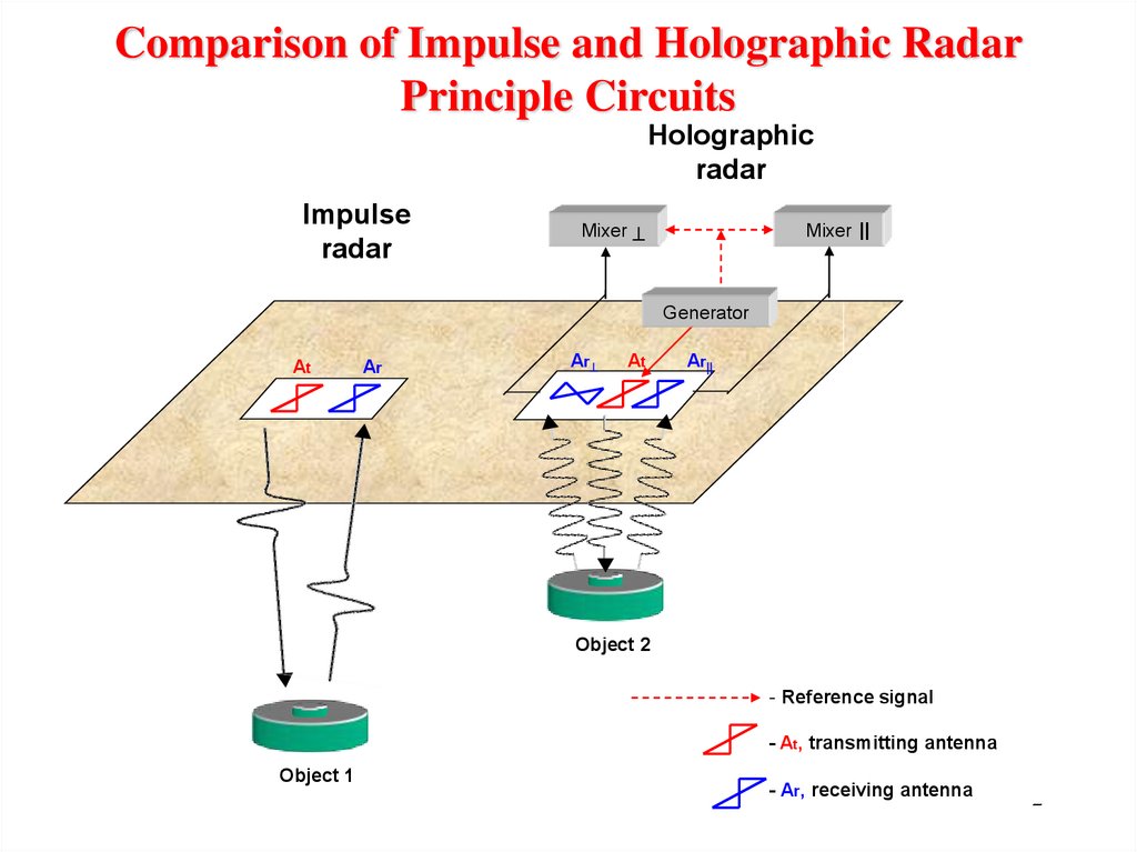
Comparison of Impulse and Holographic RadarPrinciple Circuits
Holographic
radar
Impulse
radar
Mixer
Mixer ||
Generator
At
Ar
Ar
At
Ar||
Object 2
- Reference signal
- At, transmitting antenna
Object 1
- Ar, receiving antenna
2
3.
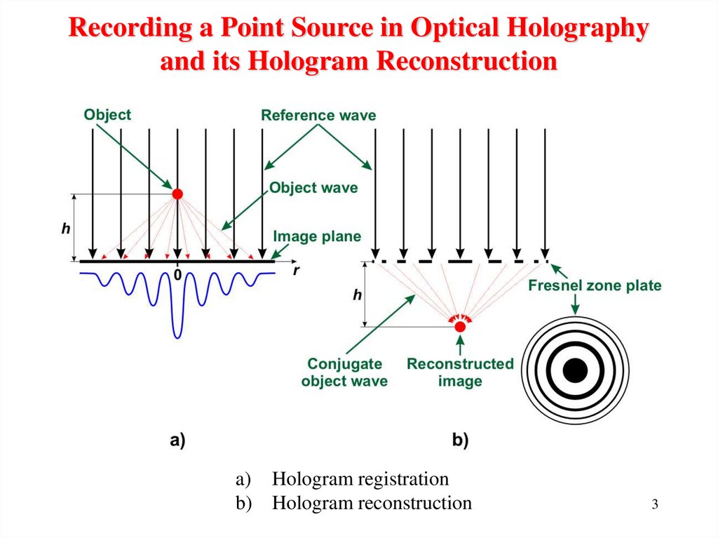
Recording a Point Source in Optical Holographyand its Hologram Reconstruction
a) Hologram registration
b) Hologram reconstruction
3
4.
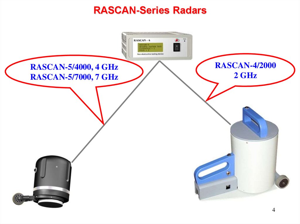
RASCAN-Series RadarsRASCAN-5/4000, 4 GHz
RASCAN-5/7000, 7 GHz
RASCAN-4/2000
2 GHz
4
5.
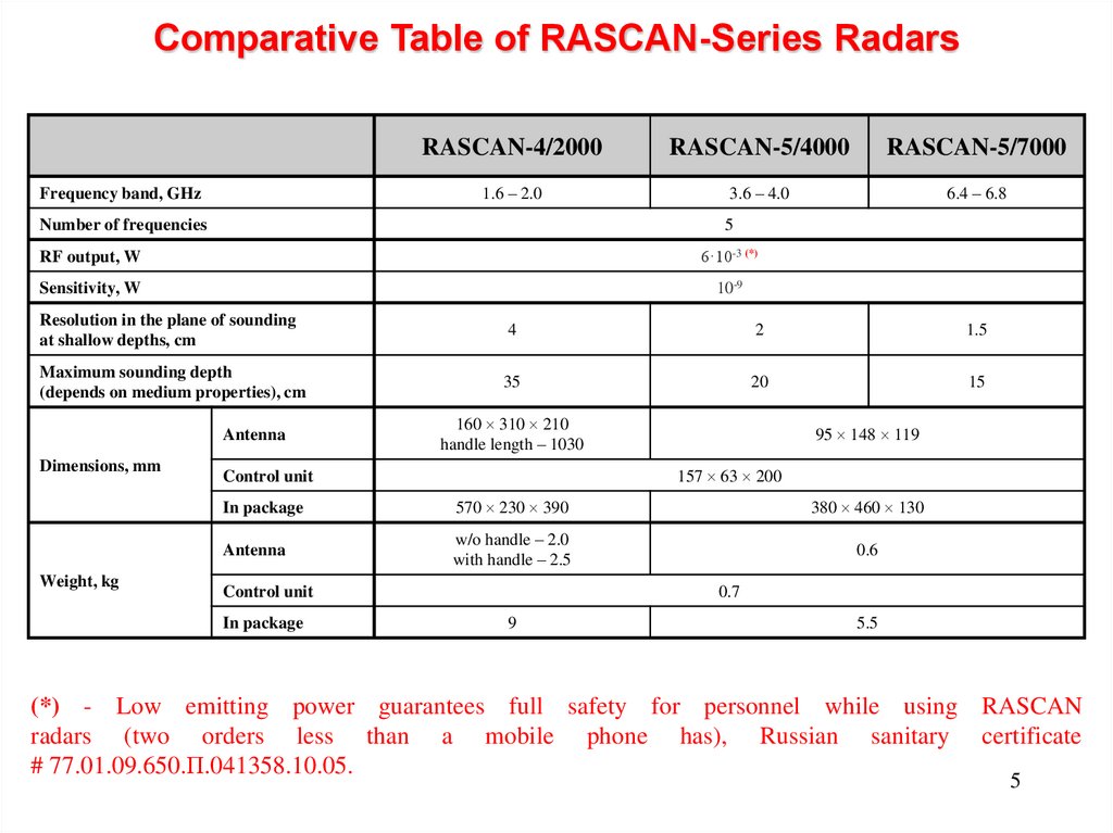
Comparative Table of RASCAN-Series RadarsFrequency band, GHz
RASCAN-4/2000
RASCAN-5/4000
RASCAN-5/7000
1.6 – 2.0
3.6 – 4.0
6.4 – 6.8
Number of frequencies
5
RF output, W
6·10-3 (*)
Sensitivity, W
10-9
Resolution in the plane of sounding
at shallow depths, cm
4
2
1.5
Maximum sounding depth
(depends on medium properties), cm
35
20
15
Antenna
Dimensions, mm
Weight, kg
160 310 210
handle length – 1030
95 148 119
157 63 200
Control unit
In package
570 230 390
380 460 130
Antenna
w/o handle – 2.0
with handle – 2.5
0.6
Control unit
In package
0.7
9
5.5
(*) - Low emitting power guarantees full safety for personnel while using RASCAN
radars (two orders less than a mobile phone has), Russian sanitary certificate
# 77.01.09.650.П.041358.10.05.
5
6. Detail View of RASCAN-5/4000 Radar
The Laboratory's staff members had been rewarded with Russian Federationgovernment's prize in the field of science and technology for creation
of the RASCAN radar technology.
6
7.
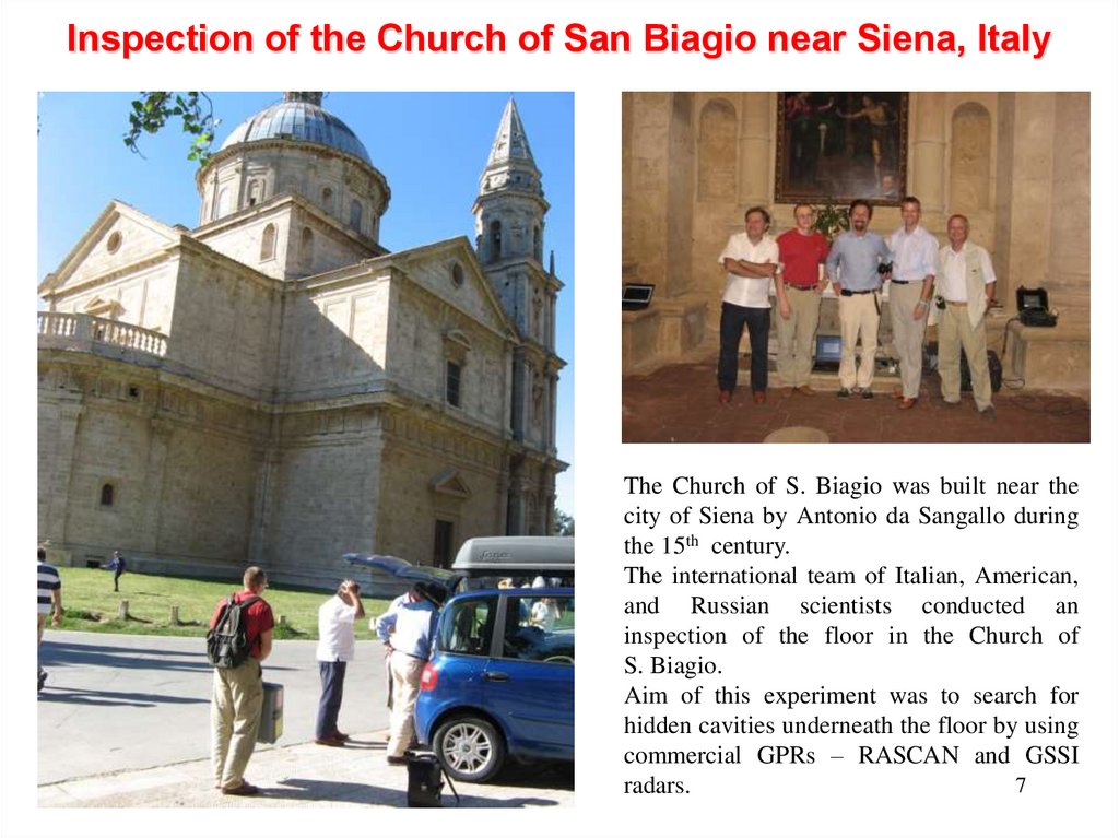
Inspection of the Church of San Biagio near Siena, ItalyThe Church of S. Biagio was built near the
city of Siena by Antonio da Sangallo during
the 15th century.
The international team of Italian, American,
and Russian scientists conducted an
inspection of the floor in the Church of
S. Biagio.
Aim of this experiment was to search for
hidden cavities underneath the floor by using
commercial GPRs – RASCAN and GSSI
7
radars.
8.
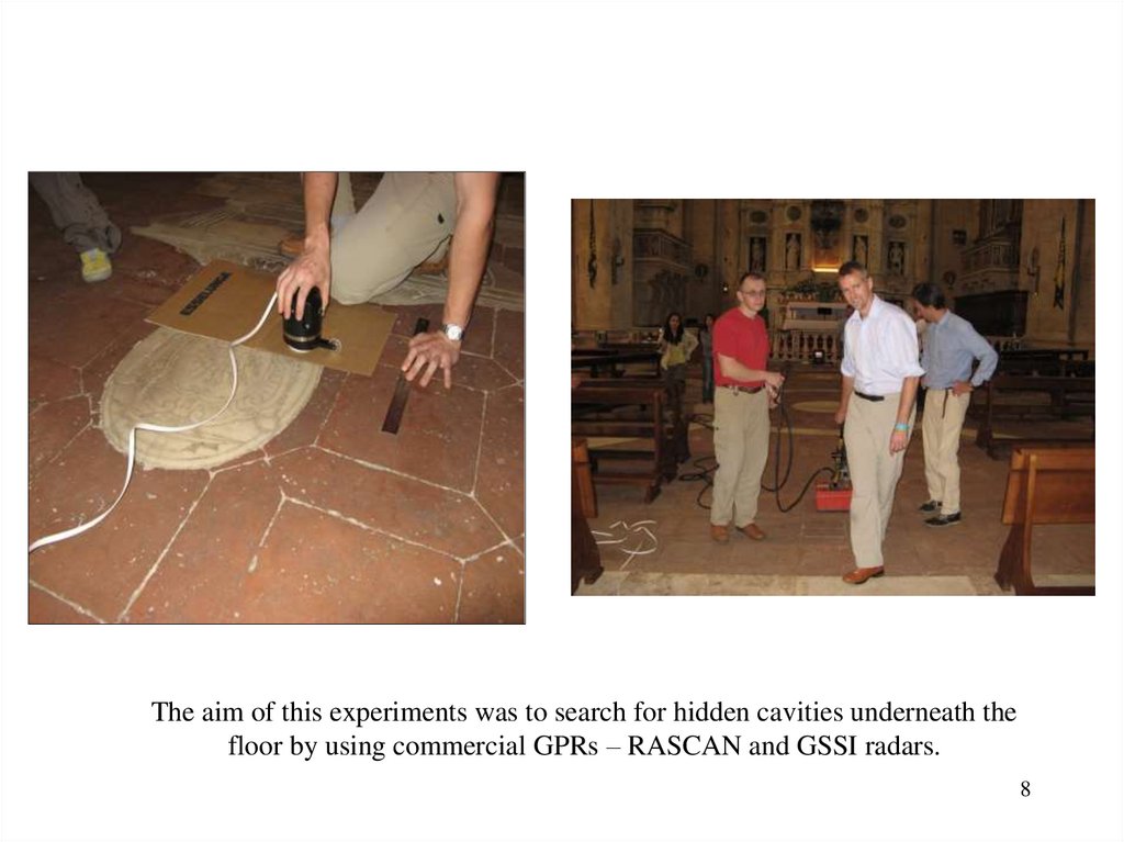
The aim of this experiments was to search for hidden cavities underneath thefloor by using commercial GPRs – RASCAN and GSSI radars.
8
9.
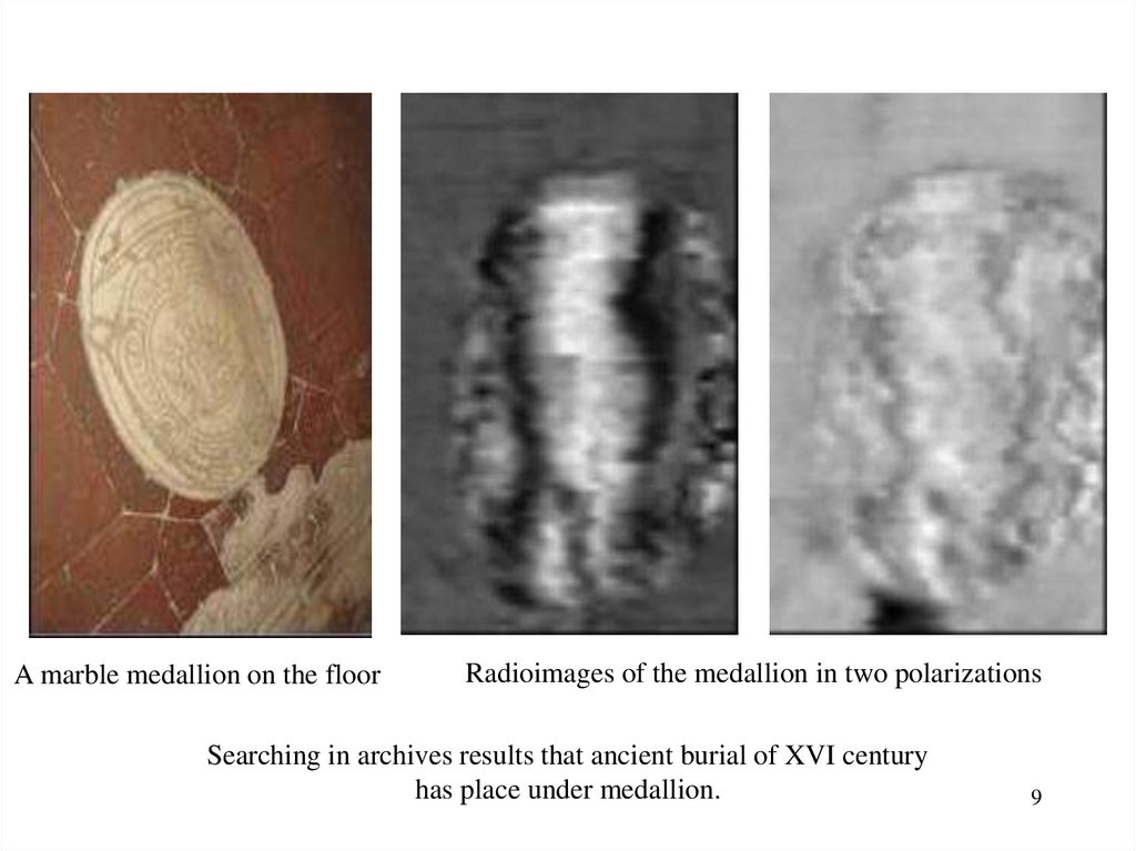
A marble medallion on the floorRadioimages of the medallion in two polarizations
Searching in archives results that ancient burial of XVI century
has place under medallion.
9
10.
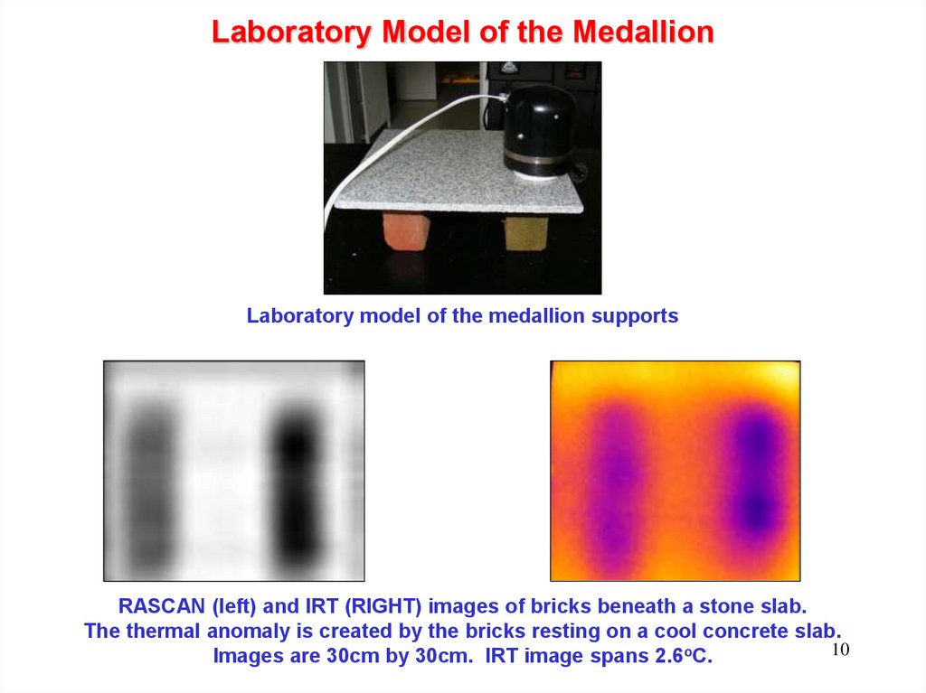
Laboratory Model of the MedallionLaboratory model of the medallion supports
RASCAN (left) and IRT (RIGHT) images of bricks beneath a stone slab.
The thermal anomaly is created by the bricks resting on a cool concrete slab.
10
Images are 30cm by 30cm. IRT image spans 2.6oC.
11.
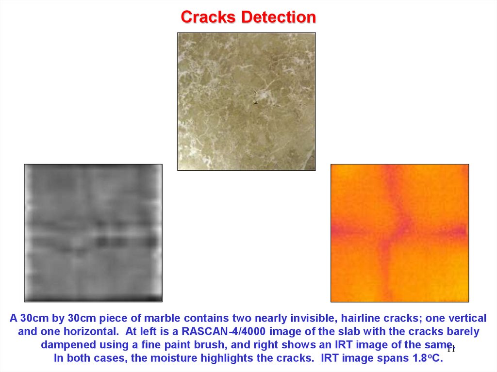
Cracks DetectionA 30cm by 30cm piece of marble contains two nearly invisible, hairline cracks; one vertical
and one horizontal. At left is a RASCAN-4/4000 image of the slab with the cracks barely
dampened using a fine paint brush, and right shows an IRT image of the same.
11
In both cases, the moisture highlights the cracks. IRT image spans 1.8oC.
12. The investigation on the Croce di San Marco with Rascan 4/4000
Description of the crossThe Cross of San Marco dates back to the mid-fourteenth
century and is attributed to Puccio di Simone.
The work can be considered one of the greatest of
Florentine painting: it reaches a total height of 6.30 meters.
The plank is made up of a vertical part, the upright of a
cross, and a horizontal part, the arm, which are joined
together by a joint between wood.
The thickness of the poplar planks is 7 cm and the entire
support, including the crosspieces, reaches a thickness of
about 25 cm for a total weight estimated at around 500 kg.
Scans
For this first phase of measurements it was decided to
scan three areas that cover the areas of the supporting
infrastructure and the area of the relief insert for the
aureole.
The work was protected with a green cloth supporting a
plexiglass sheet provided with numbered scan lines. If
necessary, the plexiglass plate was blocked by pressing it
with a wooden vice.
13.
First scanning areaThe first scanning area is positioned vertically along the trunk of the image of Christ.
In the images relating to the three intermediate frequencies of the CROSS polarization the metal nails are clearly visible,
which are used to hold the structural parts of the wooden cross together.
Always in CROSS polarization the image relative to the frequency of 3.7GHz shows in a particularly clear way the contrast
between the area laminated in gold and the area painted on wood. In this image is clearly visible a puff placed at the blood
sketch on the side.
Second scanning area
The second scan area was placed horizontally, at the top of the cross just below the halo.
Also in this scan the images of the fixing nails are confirmed, this time better visible in the images related to the
PARALLEL polarization. Note that this scan is done in an orthogonal direction with respect to the previous one.
At the three higher frequencies, both in CROSS polarization and in PARALLEL polarization, numerous striations are
visible, compatible with the flaming of the underlying wood.
Third scanning area
The third scan area is still positioned vertically but narrower than the first area to rise above the halo area.
14. Investigation on the Croce di S. Marco
Parallel – 3.6GHzCross – 3.7GHz
15.
Spurt of blood.One of the peculiarities that emerged during the survey is the presence in the radar images of a
shape that follows the sketch of blood coming from the wound on the rib.
The presence of this trace was unexpected on the area painted on the golden plate. In fact, it is not
plausible that a dielectric layer with a thickness of less than one tenth of a millimeter can modify
the module or phase of the reflected wave.
To corroborate this hypothesis, a specimen has been made with gold foil partially covered by a
layer of minio. In this case, as expected, the measurement carried out above the minio layer is not
distinguishable from that made above the gold foil without minio.
The hypothesis that seems to be more plausible is that the paint used for the san-gue sketch
contains metallic elements, and therefore can be assimilated to a non-perfect conductor. In this
case, the electric field would be only partially canceled, thus resulting in a variation of phase
different from 180 °, from which the image above.
This second hypothesis is confirmed by the analyzes carried out previously by the Opificio delle
Pietre Dure of Florence, which highlight the significant presence of lead in the paint of the blood
sketch.
Lead was used at the time of processing to make the color white, here used to represent water
mixed with blood that comes from the side of Christ.
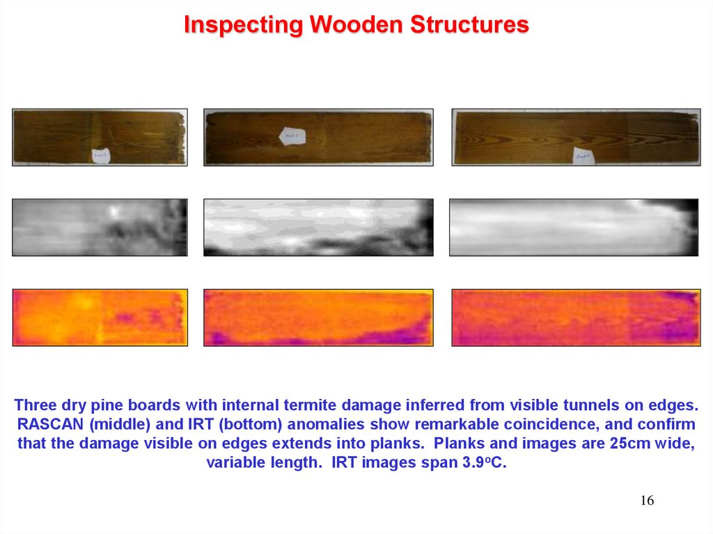
16.
Inspecting Wooden StructuresThree dry pine boards with internal termite damage inferred from visible tunnels on edges.
RASCAN (middle) and IRT (bottom) anomalies show remarkable coincidence, and confirm
that the damage visible on edges extends into planks. Planks and images are 25cm wide,
variable length. IRT images span 3.9oC.
16
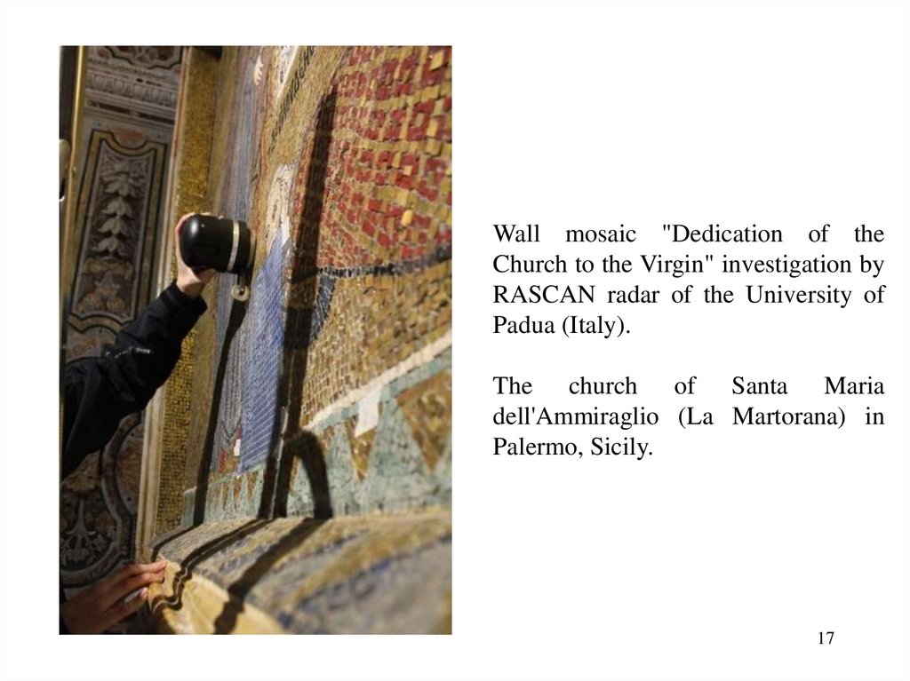
17.
Wall mosaic "Dedication of theChurch to the Virgin" investigation by
RASCAN radar of the University of
Padua (Italy).
The church of Santa Maria
dell'Ammiraglio (La Martorana) in
Palermo, Sicily.
17
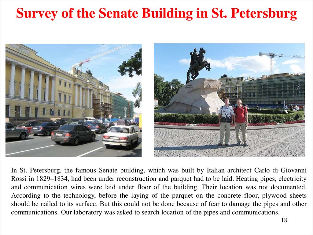
18.
Survey of the Senate Building in St. PetersburgIn St. Petersburg, the famous Senate building, which was built by Italian architect Carlo di Giovanni
Rossi in 1829–1834, had been under reconstruction and parquet had to be laid. Heating pipes, electricity
and communication wires were laid under floor of the building. Their location was not documented.
According to the technology, before the laying of the parquet on the concrete floor, plywood sheets
should be nailed to its surface. But this could not be done because of fear to damage the pipes and other
communications. Our laboratory was asked to search location of the pipes and communications.
18
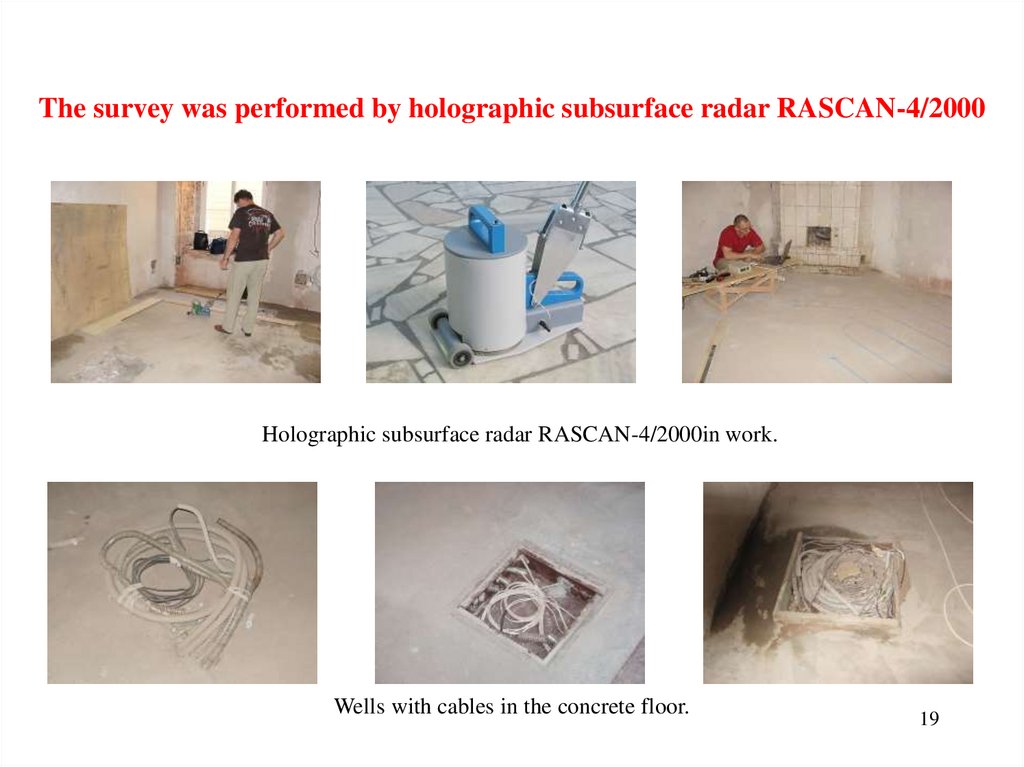
19.
The survey was performed by holographic subsurface radar RASCAN-4/2000Holographic subsurface radar RASCAN-4/2000in work.
Wells with cables in the concrete floor.
19
20.
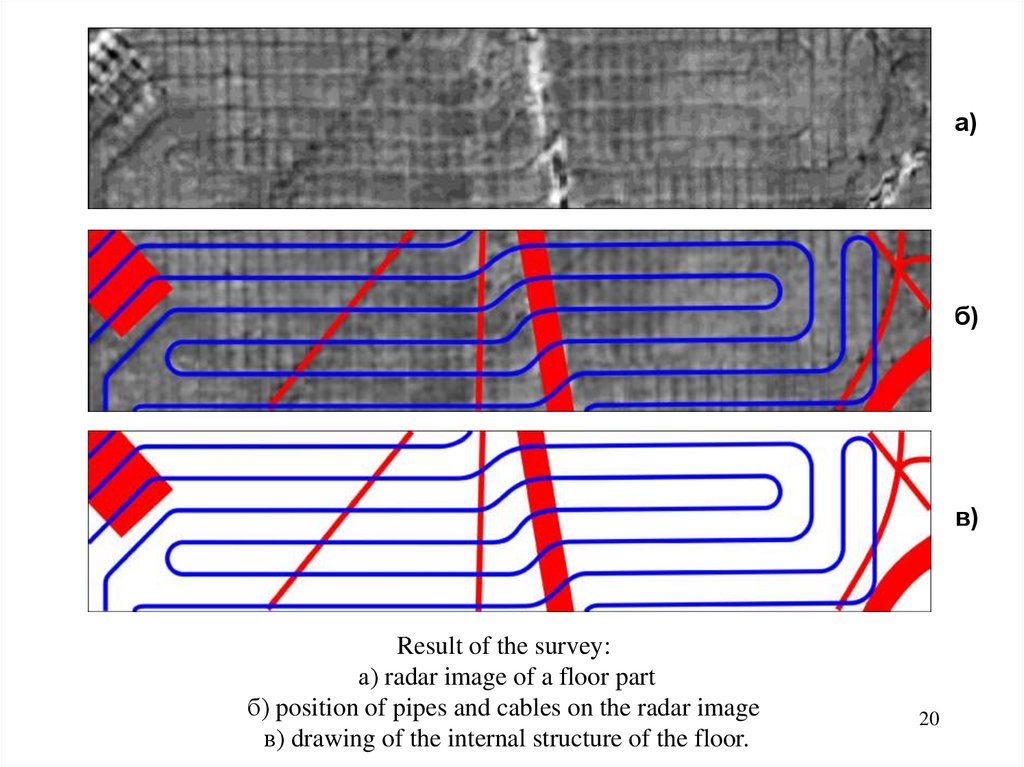
а)б)
в)
Result of the survey:
а) radar image of a floor part
б) position of pipes and cables on the radar image
в) drawing of the internal structure of the floor.
20
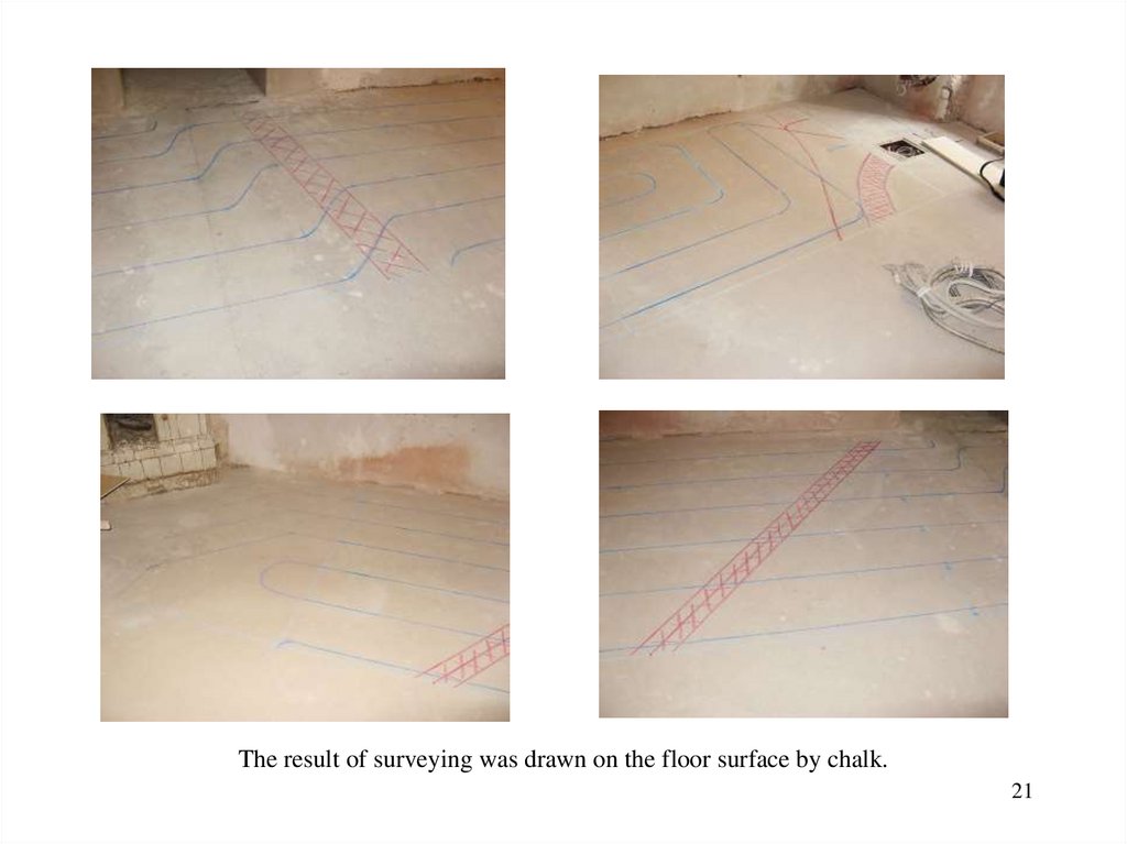
21.
The result of surveying was drawn on the floor surface by chalk.21
22. An Example of Holographic Subsurface Radar Image
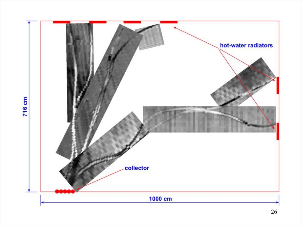
In this image, it is possible to see how the heater pipes are bending over the cable.22
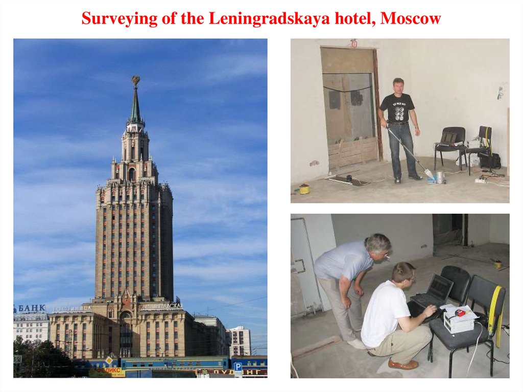
23.
Surveying of the Leningradskaya hotel, Moscow23
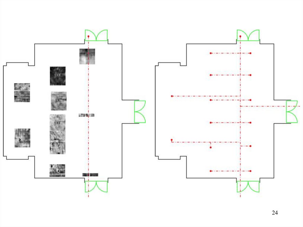
24.
2425. Surveying of a Concrete Floor
Heating plastic pipeConcrete floor inspection
25
26.
2627. Examples of RASCAN Diagnostics
Radar images of the ferroconcrete wallsRadar images of the cinder concrete briks walls.
Black spots are voids in the briks.
Stone wall under plaster
A ventilation channel
in concrete wall
An electrical socket and
wire in concrete wall
A hand under table
27
28.
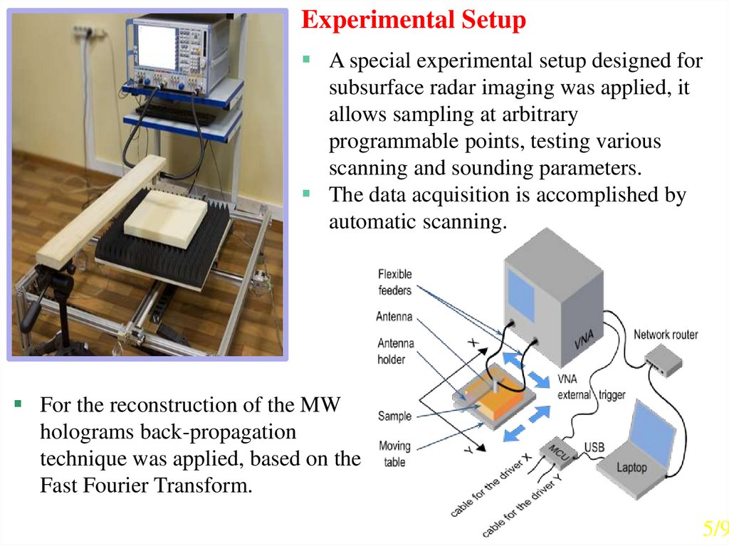
Experimental SetupA special experimental setup designed for
subsurface radar imaging was applied, it
allows sampling at arbitrary
programmable points, testing various
scanning and sounding parameters.
The data acquisition is accomplished by
automatic scanning.
For the reconstruction of the MW
holograms back-propagation
technique was applied, based on the
Fast Fourier Transform.
5/9
29.
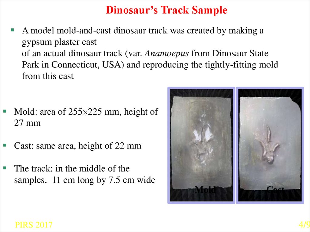
Dinosaur’s Track SampleA model mold-and-cast dinosaur track was created by making a
gypsum plaster cast
of an actual dinosaur track (var. Anamoepus from Dinosaur State
Park in Connecticut, USA) and reproducing the tightly-fitting mold
from this cast
Mold: area of 255 225 mm, height of
27 mm
Cast: same area, height of 22 mm
The track: in the middle of the
samples, 11 cm long by 7.5 cm wide
Mold
PIRS 2017
Cast
4/9
30.
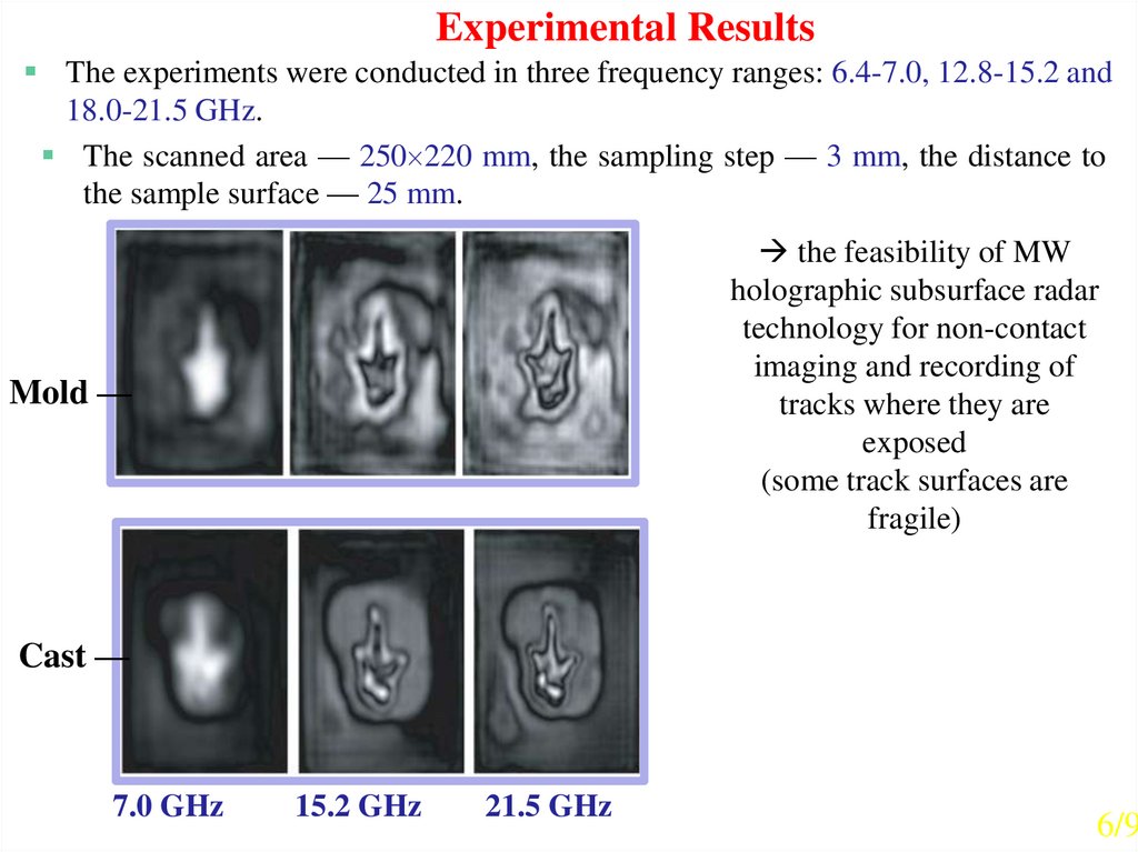
Experimental ResultsThe experiments were conducted in three frequency ranges: 6.4-7.0, 12.8-15.2 and
18.0-21.5 GHz.
The scanned area — 250 220 mm, the sampling step — 3 mm, the distance to
the sample surface — 25 mm.
the feasibility of MW
holographic subsurface radar
technology for non-contact
imaging and recording of
tracks where they are
exposed
(some track surfaces are
fragile)
Mold —
Cast —
7.0 GHz
15.2 GHz
21.5 GHz
6/9
31. Columbia’s Accident
Space Shuttle Columbia take offon 16th of January 2003.
Columbia’s remains after unfortunate landing on
of February 2003, Flight International, 29 April-5
May 2003, pp. 26-29.
Collected on the ground remains of Columbia were laid
out in a hangar by the NASA Investigation Board.
1st
31
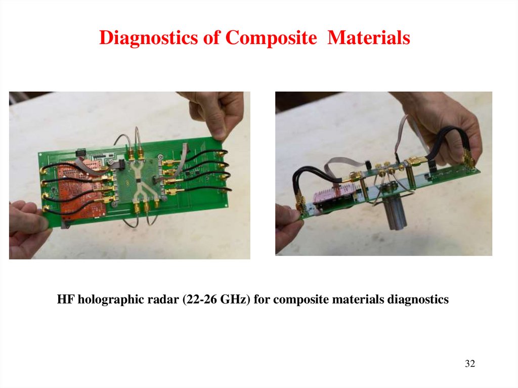
32.
Diagnostics of Composite MaterialsHF holographic radar (22-26 GHz) for composite materials diagnostics
32
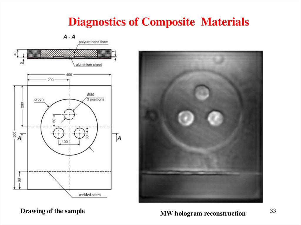
33.
Diagnostics of Composite MaterialsDrawing of the sample
MW hologram reconstruction
33
34.
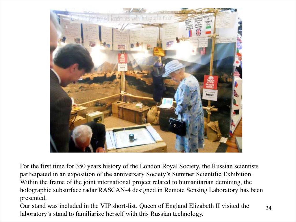
For the first time for 350 years history of the London Royal Society, the Russian scientistsparticipated in an exposition of the anniversary Society’s Summer Scientific Exhibition.
Within the frame of the joint international project related to humanitarian demining, the
holographic subsurface radar RASCAN-4 designed in Remote Sensing Laboratory has been
presented.
Our stand was included in the VIP short-list. Queen of England Elizabeth II visited the
34
laboratory’s stand to familiarize herself with this Russian technology.
35.
CONCLUSIONHolographic subsurface radar technology is not universal one.
However in some cases it can be useful and unique
in obtained results.
It gives opportunity to record images of objects’ internal
structures at one-side access to them.
In this quality RASCAN radars differ from X-ray devices that
need two-side access to the structure under consideration.
Two-side access is impossible in the most cases.
35
36. ACKNOWLEDGMENTS
Support for this work was providedby the Russian Science Foundation under project # 21-19-00043
Russian Foundation for Basic Research
under projects #19-57-18001 and # 20-57-46004 .
Authors express their gratitude
to Dr. Roberto Olmi, IFAC CNR – Italy,
for his help in investigation of the Croce di San Marco.
36
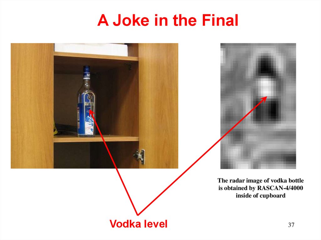
37.
A Joke in the FinalThe radar image of vodka bottle
is obtained by RASCAN-4/4000
inside of cupboard
Vodka level
37