


 Промышленность
Похожие презентации:


Bottom mounted freezer type
1.
SAMSUNG Bottom-Mounted-Freezer RefrigeratorRB3000 B-PJT
BOTTOM MOUNTED FREEZER TYPE
MODEL NAME : RB33*3*****
2020. 6. 9
Refrigerator Division
2.
Contents1. PRECAUTIONS (SAFETY WARNINGS).............3
2. PRODUCT SPECIFICATIONS ...................7
3. DISASSEMBLY & REASSEMBLY.................14
4. TROUBLE SHOOTING........................ 44
5. PCB/PBA DAIGRAM ........................ 84
6. WIRING DIAGRAM ......................... 85
7. BLOCK DIAGRAM........................... 86
8. CYCLE DIAGRAM .......................... 87
9. SENSOR LAYOUT .......................... 88
10. REFERENCE INFORMATION.................. 89
2
3.
1. PRECAUTIONS (SAFETY WARNINGS)- Unplug the power supply when repairing/replacing electronic control system.
Beware of electric shock.
- Use the rated electronic control device.
Check the model name, rated voltage, rated current, working temperature and so on.
- During maintenance, make sure that the harness is not immersed in water and is connected firmly.
It will not be disconnected due to certain external force.
- During maintenance, it is required to remove dust or other foreign substances on the gluey housing,
harness and connector.
Prevent the electric leakage due to aging or fire hazard in short circuit.
- Check for water penetration into the electronic control system. If water penetrates into the system,
take necessary measures, for example, replacing the related components or covering with insulating
tape.
- After the troubleshooting, check the assembly status of the disassembled components. It shall be
the same as that before maintenance.
- Check the surrounding environment of the refrigerator. If the refrigerator is installed in humid place
or unstable place, it is required to change the installation position.
- Ground it as needed. It shall be grounded especially in case of danger of electric shock.
- Do not overload the socket. Check whether the power wire or socket is damaged, squeezed, cut off
or thermally deformed. Immediately repair or replace the defective power cord/socket. Make sure
that the power cord is not broken or pressed by a heavy object.
- Do not store perishable food or bottle in the freezer.
- The user is not allowed to repair the refrigerator.
- Do not store the materials other than food. It is difficult for the refrigerator to maintain the accurate
temperature required for substances like drugs and chemical substances.
Flammable materials (alcohol, benzene, hydrogen, liquefied petroleum gas, etc.) are in danger of
explosion.
3
4.
1. PRECAUTIONS (SAFETY WARNINGS)• Read all instructions before repairing the product and keep to the instructions in order to prevent da
nger or property damage.
4
5.
1. PRECAUTIONS (SAFETY WARNINGS)5
6.
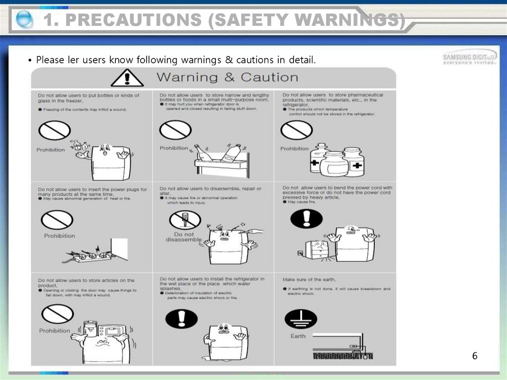
1. PRECAUTIONS (SAFETY WARNINGS)• Please ler users know following warnings & cautions in detail.
6
7.
2. PRODUCT SPECIFICATIONSTo do list
product feature
NO FROST
INVERTER COMP
INTERNAL LED DISPLAY
MULTI FLOW
7
8.
2. PRODUCT SPECIFICATIONSTo do list
product feature
DISPLAY
LED LAMP
Dairy Bin
SHELF REF
Door Bin
TRAY VEG
RECESSED HANDLE
TRAY FRE
8
9.
2. PRODUCT SPECIFICATIONSTo do list
SPECIFICATION
9
10.
2. PRODUCT SPECIFICATIONSTo do list
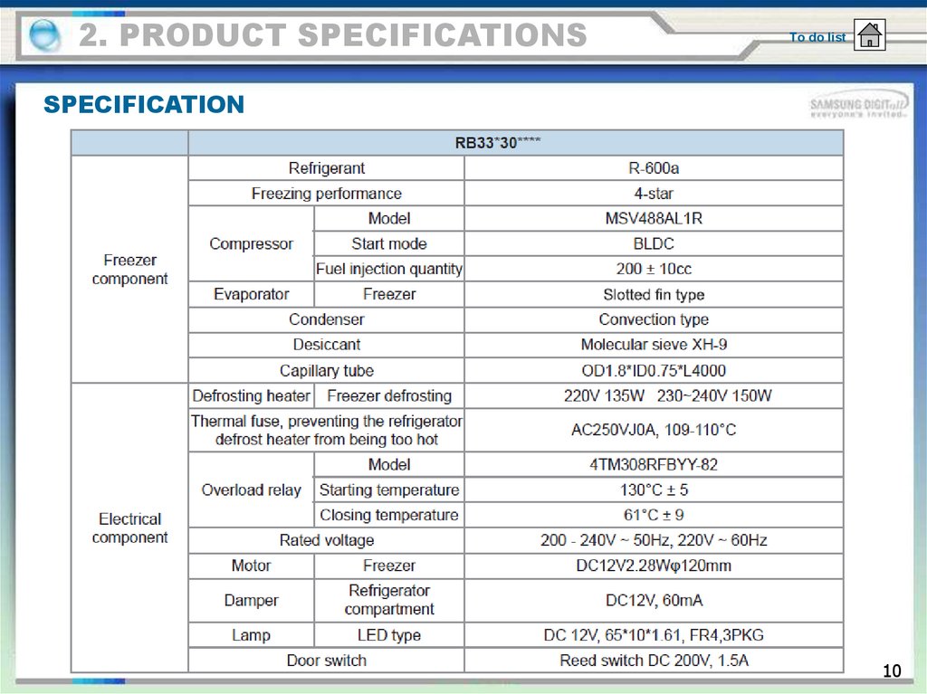
SPECIFICATION
10
11.
2. PRODUCT SPECIFICATIONSSPECIFICATION
11
12.
2. PRODUCT SPECIFICATIONSTo do list
DIMENSION
12
13.
2. PRODUCT SPECIFICATIONSTo do list
Display
①
②
01 Freezer
• Press the Freezer button to set the freezer to desired temperature from range between -15 °C an
d -23 °C. Default set temperature is set on -19 °C
• Press this button for 3 seconds to activate the Power Freeze function.
Power Freeze indicator ( ) will light up
• If you need to freeze large amount of food stuff, activate Power Freeze function 20 hours before.
• To deactivate this function, press the Freezer button for 3 seconds.
02 Fridge
• Press the Fridge button to set the fridge to desired temperature between 1 °C and 7 °C. Default
set temperature is set on 3 °C
• Press this button for 3 seconds to activate the Power Cool function.
Power Cool indicator ( ) will light up
• If you need to cool the perishable food rapidly, or if the temperature of the fridge rises rapidly (f
or example, if the refrigerator door is not closed), this function will be very useful.
• To deactivate this function, press the Fridge button for 3 seconds.
13
14.
3. DISASSEMBLY & REASSEMBLYPRECAUTIONS
Unplug the refrigerator before cleaning and making repairs.
Do not dissemble or repair the refrigerator by yourself.
- You run risk of causing a fire, malfunction and/or personal injury.
• Remove any foreign matter or dust from the power plug pins.
- Otherwise there is a risk of fire.
• Do not use a cord that shows cracks or abrasion damage along its length or at either end.
• Do not plug several appliances into the same multiple power board. The refrigerator should always be plugged into
its own individual electrical which has a voltage rating that matched the rating plate.
- This provides the best performance and also prevents overloading house wiring circuits, which could cause a fire
hazard from overheated wires.
• Do not install the refrigerator in a damp place or place where it may come in contact with water.
- Deteriorated insulation of electrical parts may cause an electric shock or fire.
• The refrigerator must be grounded.
- You must ground the refrigerator to prevent any power leakages or electric shocks caused by current leakage fro
m the refrigerator.
• Do not put bottles or glass containers in the freezer.
- When the contents freeze, the glass may break and cause personal injury.
• Do not store volatile or flammable substances in the refrigerator.
- The storage of benzene, thinner, alcohol, ether, LP gas and other such products may cause explosions.
14
15.
3. DISASSEMBLY & REASSEMBLYTOOL NEEDED
이미지
품명
사용
Phillips Head Driver
Use for assembling and disassembling of
screw
Flat Head Driver
Use for assembling and disassembling of
HomeBar, Dispenser, Deli Cartessen Box,
Main PBA etc...
Socket Wrench Ø8mm, 12mm
Use for assembling and
disassembling of Door Hinge
15
16.
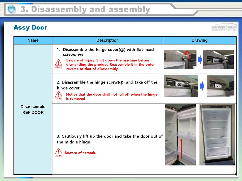
3. Disassembly and assemblyAssy Door
Name
Description
1. Disassemble the hinge cover(①) with flat-head
screwdriver
Beware of injury. Shut down the machine before
dismantling the product. Reassemble it in the order
reverse to that of disassembly.
2. Disassemble the hinge screw(②) and take off the
hinge cover
Drawing
①
②
Notice that the door shall not fall off when the hinge
is removed
Disassemble
REF DOOR
3. Cautiously lift up the door and take the door out of
the middle hinge
Beware of scratch.
16
17.
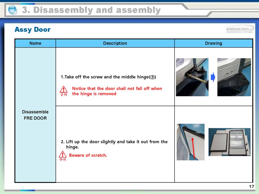
3. Disassembly and assemblyAssy Door
Name
Description
Drawing
③
1.Take off the screw and the middle hinge(③)
Notice that the door shall not fall off when
the hinge is removed
Disassemble
FRE DOOR
2. Lift up the door slightly and take it out from the
hinge.
Beware of scratch.
17
18.
3. Disassembly and assemblyRefrigerator compartment
Name
Shelf
TRAY VEG
Description
Drawing
Raise it so that it can be pulled outward
1. Pull the drawer outward as much as possible.
2. Raise it up slightly and take it out.
18
19.
3. Disassembly and assemblyRefrigerator compartment
Name
Plastic drawer of
Freezer
Description
Drawing
1. Pull the drawer outward as much as possible.
2. Raise it up slightly and take it out.
19
20.
3. Disassembly and assemblyRefrigerator compartment
Name
Description
Drawing
1. Take out all shelves and plastic drawers.
2. Unscrew 3 screws of the refrigerator compartment,
as shown in the figure.
3. Separate the lower left Housing.
REF DUCT
During the dismantling, ensure that the equipment
has stopped operation.
—— The assembly sequence of refrigerator is reverse
to that of disassembly.
—— The thermistor of the refrigerator is situated in the
refrigerator.
20
21.
3. Disassembly and assemblyRefrigerator compartment
Name
DUCT FRE
Description
Drawing
1. Take out all drawers.
2. Remove 3 screws.
3. Pull out the upper shelf of the freezer if possible.
4. Use both hands to pull out the evaporator cover
from down to up.
During the dismantling, ensure that the equipment
has stopped operation.
21
22.
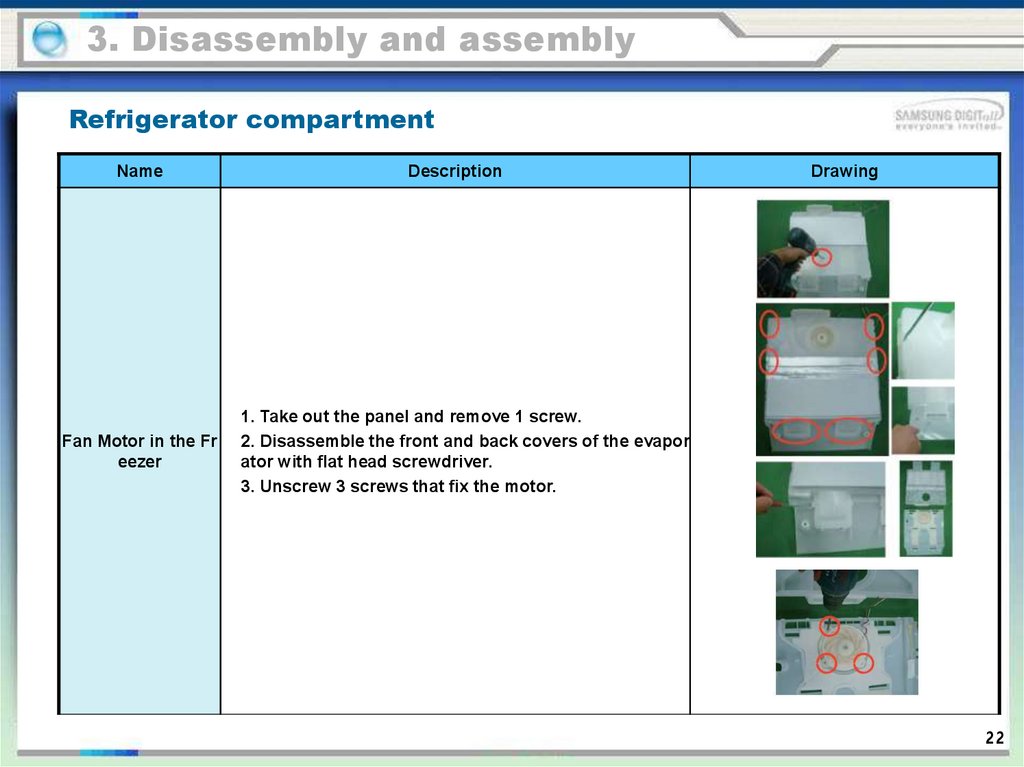
3. Disassembly and assemblyRefrigerator compartment
Name
Fan Motor in the Fr
eezer
Description
Drawing
1. Take out the panel and remove 1 screw.
2. Disassemble the front and back covers of the evapor
ator with flat head screwdriver.
3. Unscrew 3 screws that fix the motor.
22
23.
3. Disassembly and assemblyRefrigerator compartment
Name
FRE EVAP
Description
Drawing
1. Take off the freezer duct.
2. Disconnect the connector. (Heater, hot fuse and
Thermistor.)
3. Cut open the pipe. The equipment is filled with R600
a or R134a refrigerant, when the welding is very dange
rous.
4. Dismantle the evaporator.
5. Seal the system with the steps same as above.
23
24.
3. Disassembly and assemblyRefrigerator compartment
Name
Description
Main PBA
1. Take off the steel cover on the back of refrigerator.
2. Separate the housing and then dismantle PBA.
Drawing
24
25.
3. Disassembly and assemblyDelivery & Install
NO
Name
1
Check the size of the entran
ce
2
Delivery of Door
Description
Drawing
Before moving the refrigerator, check t
he size of the elevator and doorway.
Please move the door first.
Be careful not to scratch the
door.
3
Delivery of Refrigerator
Pack the refrigerator with a box to pre
vent scratching the sides.
Move the fridge in pairs.
25
26.
3. Disassembly and assemblyDelivery & Install
NO
Name
Description
1
To prevent damage to the floor, please use
packing boxes and floor mats on the floor
Push the refrigerator int
※ Make sure the technician has the space t
o the reserved space.
o set up the refrigerator.
2
If the front and back of the refrigerator are
not level, the refrigerator may break down.
Check refrigerator level Use wood carving, plastic and other hard th
ings to clip the refrigerator under the refrig
erator and tape fixed.
3
Insert level JIG
Drawing
Place the Rear caster touch on both sides
on the floor and clip in the fridge.
26
27.
3. Disassembly and assemblyDelivery & Install
NO
Name
Description
4
Adjust refrigerator level
Insert a flat-head (-) screwdriver into th
e refrigerator adjusting leg and adjust t
he left / right side level.
5
Remove JIG
Pull out the JIG on the front of the fridg
e.
6
Door level adjustment
Turn the screw clockwise or counterclo
ckwise to adjust the level of the door.
7
Explain to customers how to
use the product.
Explain the refrigerator temperature set
ting method, purchase other accessorie
s method.
Drawing
27
28.
3. Disassembly and assemblyTo do list
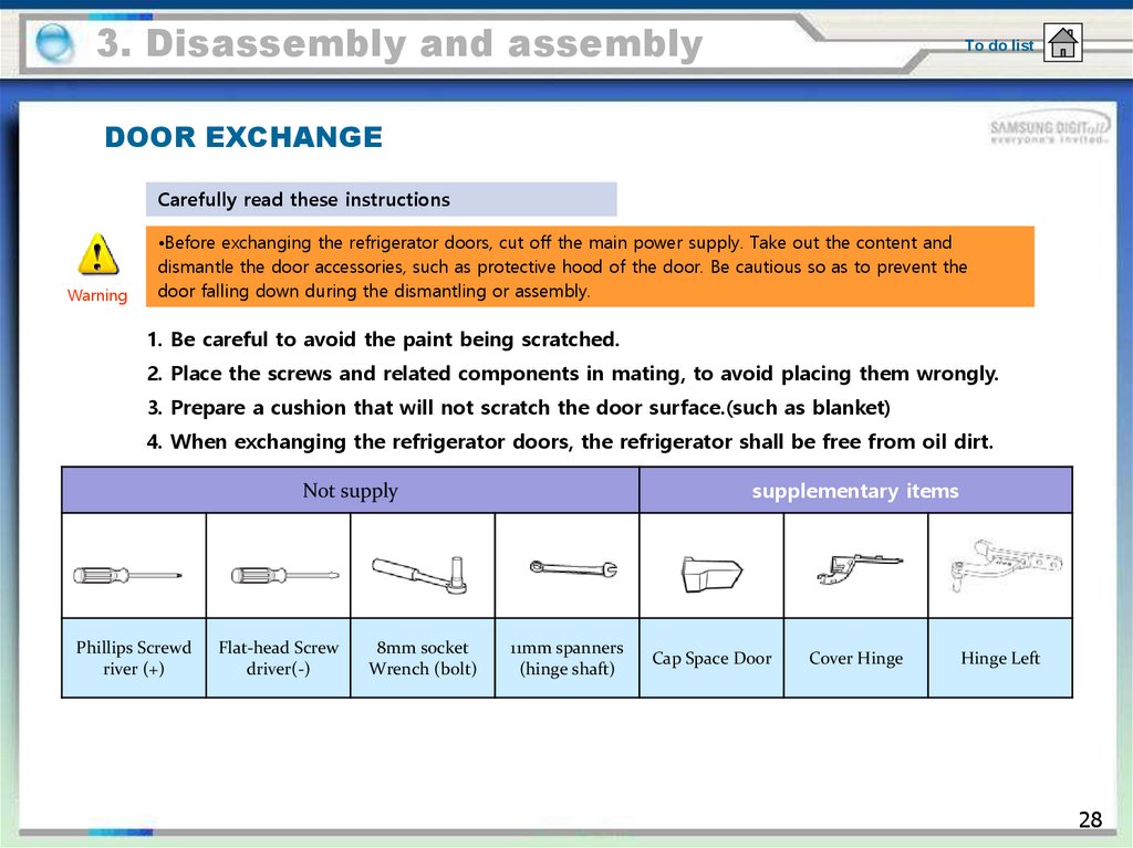
DOOR EXCHANGE
Carefully read these instructions
Warning
•Before exchanging the refrigerator doors, cut off the main power supply. Take out the content and
dismantle the door accessories, such as protective hood of the door. Be cautious so as to prevent the
door falling down during the dismantling or assembly.
1. Be careful to avoid the paint being scratched.
2. Place the screws and related components in mating, to avoid placing them wrongly.
3. Prepare a cushion that will not scratch the door surface.(such as blanket)
4. When exchanging the refrigerator doors, the refrigerator shall be free from oil dirt.
supplementary items
Not supply
Phillips Screwd
river (+)
Flat-head Screw
driver(-)
8mm socket
Wrench (bolt)
11mm spanners
(hinge shaft)
Cap Space Door
Cover Hinge
Hinge Left
28
29.
3. Disassembly and assemblyDOOR EXCHANGE
Name
Description
1. Disassemble the Cover Hinge(①) with flat-head
screwdriver.
Shut down the machine before dismantling the
product. Reassemble it in the order reverse to
that of disassembly
2. Unscrew the hinge screw(②) and take off the hinge
Drawing
①
②
Be cautious so as to prevent the door falling
down during the dismantling.
DOOR EXCHANGE
3. Vertically lift up the door and dismantle it
from the hinge.
Door is very heavy. Operate cautiously to
avoid being injured.
29
30.
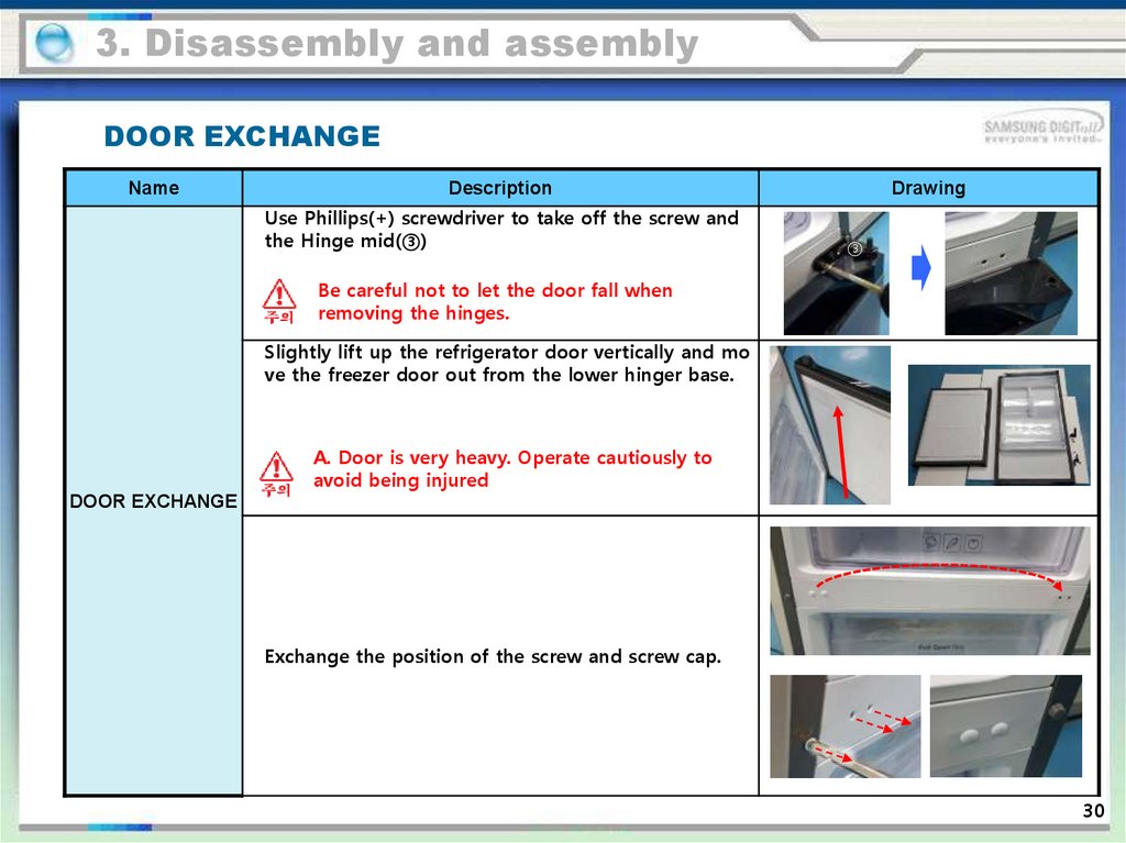
3. Disassembly and assemblyDOOR EXCHANGE
Name
Description
Use Phillips(+) screwdriver to take off the screw and
the Hinge mid(③)
Drawing
③
Be careful not to let the door fall when
removing the hinges.
Slightly lift up the refrigerator door vertically and mo
ve the freezer door out from the lower hinger base.
A. Door is very heavy. Operate cautiously to
avoid being injured
DOOR EXCHANGE
Exchange the position of the screw and screw cap.
30
31.
3. Disassembly and assemblyDOOR EXCHANGE
Name
Description
Drawing
During the decomposition process, the hinge is convert
ed from bottom to top and assembled on the left side
(two bolts, one screw).
DOOR EXCHANGE
To remove the lower right corner of the freezer door,
remove the two screws.
(hinges, AUTOCLOSE, GROMMET HINGE removal)
to protect the refrigerator, it is required to
place a big cardboard under the refrigerator.
31
32.
3. Disassembly and assemblyDOOR EXCHANGE
Name
Description
Drawing
Disassemble AUTOCLOSE、GROMMET HINGE
DOOR EXCHANGE
SHAFT HINGE→GROMMET HINGE→AUTOCLOSE
assemble in the left corner of the refrigerator do
or in order.
Assemble two screws.
to protect the refrigerator, it is required to
place a big cardboard under the refrigerator.
32
33.
3. Disassembly and assemblyDOOR EXCHANGE
Name
Description
Drawing
Cautiously place the refrigerator flat.
Remove the footing and lower hinge.
to protect the refrigerator, it is required to
place a big cardboard under the refrigerator.
DOOR EXCHANGE
Assemble the removed middle hinge on the left si
de.
33
34.
3. Disassembly and assemblyDOOR EXCHANGE
Name
Description
Drawing
Assemble the Freezer door in
combination with the middle hinge
to protect the refrigerator, it is required to
place a big cardboard under the refrigerator.
DOOR EXCHANGE
Prepare the Hinge Low that has been decompose
d.
34
35.
3. Disassembly and assemblyDOOR EXCHANGE
Name
Description
Drawing
Separate the shaft Hinge and assemble it on the
opposite side
DOOR EXCHANGE
Place the freezer door behind the middle hinge a
nd assemble the lower hinge on the left side of
the refrigerator.
(The refrigerator is in the lying status)
35
36.
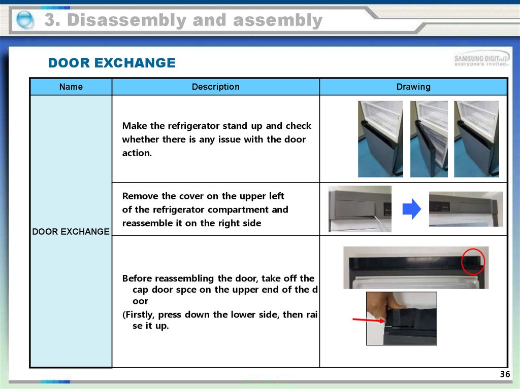
3. Disassembly and assemblyDOOR EXCHANGE
Name
Description
Drawing
Make the refrigerator stand up and check
whether there is any issue with the door
action.
Remove the cover on the upper left
of the refrigerator compartment and
reassemble it on the right side
DOOR EXCHANGE
Before reassembling the door, take off the
cap door spce on the upper end of the d
oor
(Firstly, press down the lower side, then rai
se it up.
36
37.
3. Disassembly and assemblyDOOR EXCHANGE
Name
DOOR EXCHANGE
Description
Drawing
Assemble the left hinge, hinge cover and cap doo
r space provided when purchasing the refrigera
tor
37
38.
3. Disassembly and assemblyDOOR EXCHANGE
Name
DOOR EXCHANGE
Description
Drawing
Check whether the door action is abnormal
Ensure that the refrigerator door acts normally.
38
39.
3. Disassembly and assemblyReplace the custom panel
Name
Description
Drawing
Dismantle 3 blocking covers above REF d
oor
Replace the custom
panel
(REF)
Separate the panel with the absorber.
(Raise it up and extend it outward.)
To prevent any damage, add the cushion
on the floor.
39
40.
3. Disassembly and assemblyReplace the custom panel
Name
Replace the custom
panel
(REF)
Description
Snap the panel prepared for switching into the TR
IM position.
Confirm door clearance after panel assembly
Drawing
不要有太多偏差
Install three COVER CAP DOOR on the upper side
40
41.
3. Disassembly and assemblyReplace the custom panel
Name
Description
Drawing
Disassemble three COVER CAP DOOR in the
handle of the freezer door and remove 3 sc
rews
Replace the custom
panel
(FRE)
Remove the panel with the absorber.
(Pull it backward and then raise it up.)
To prevent any damage, add the cushion
on the floor.
41
42.
3. Disassembly and assemblyReplace the custom panel
Name
Description
Drawing
Assemble the prepared replaceable
panel in Fixer position for assembly
(with Absorber)
Replace the custom
panel
(FRE)
Check whether the panel is properly
assembled
Assembly three screws and assemble the C
ap door cover.
42
43.
4. Troubleshooting4-1. Troubleshooting checklist
4-1-1. Test function (forced Operation /forced defrost)
1. Press the “freezer” button on PCB control panel and “refrigerator compartment” button for more than 4 seconds,
so that the panel will display for 3 seconds at the interval of 0.5 second. Then press “freezer” button. Then, it goes
into the test mode.
2. In the test mode, all display buttons will be used as the test button.
3. When test button is pressed, the refrigerator will operate in the following sequence.
Forced Operation → Forced defrost → Function removal (normal operation)
4. It is recommended to insert the plug again to terminate the operation of test function.
1) Select the test function
②
①
① Press the “freezer” button and “refrigerator compartment” button for 4 seconds.
② Enter the test mode and press the “freezer” button.
43
44.
4. Troubleshooting4-1. Troubleshooting checklist
4-1-1. Test function (forced Operation /forced defrost)
2) Test mode description
1) Forced Operation Function
1-1) When any button is pressed once during the Test Mode, it will enter the Forced Operation. When it starts the
Forced Operation, the LED Lamps indicating the Fridge Temperatures (1℃, 2℃, 3℃, 5℃, 7℃) and the Freezer
Temperatures (-23℃,-21℃,-19℃, -17℃,-15℃) will be on showing that it is on the Forced Operation. At this time,
it starts alarming with “Beep” sounds.
1-2) When the Forced Operation is selected, the compressor starts without a 7-minute delay in any operation
mode. At this time, when it is in a Defrost mode, it stops defrosting and the Forced Operation begins. (If the
Forced Operation begins as soon as the compressor stops, it may cause the overload. So, take care when entering
into the Forced Operation.)
1-3) When the Forced Operation is selected, the compressor and the F-Fan operate for 24 hours without stopping.
1-4) When the unit is shifted to the Forced Operation, the Freezer and the Fridge temperatures will be automatically
set to -23℃ and 1℃ respectively.
1-5) When the Forced Operation is selected, the Power Freeze function won't work. (All the buttons will operate
normally.) And, when the Power Freeze function is selected, the Power Freeze LED will go off in 10 seconds.
1-6) When the Forced Defrost or Test Cancellation Mode is selected within a minute with the Forced Operation being
selected, the set temperature will be changed to the previously set operating temperature.
1-7) The alarm sound during the Forced Operation keeps on until the Forced Operation completes and there is no
cancellation function.
44
45.
4. Troubleshooting4-1. Troubleshooting checklist
4-1-1. Test function (forced Operation /forced defrost)
2) Forced Defrost Function
2-1) When it is on the Forced Operation during the Test Mode, press any button once. Then, the Forced Operation
will stop immediately and it will go into the Forced F-Defrost. When it enters the Forced F-Defrost, it indicates that
it is on the Forced F-Defrost mode by turning on "3℃", "5℃" and "7℃" temperature LEDs on the Fridge Display
Panel and "-15℃”, “-17℃” and “-19℃" temperature LEDs on the Freezer Display Panel.
2-2) At this time, it sends out "Beeping" sound for 3 seconds. This alarm sound repeats 0. 5 sec On and 0.5 sec
Off which keeps on until the Forced F-Defrost finishes.
3) TEST MODE Cancel
3-1) When turning the display panel into the Test mode and pressing the TEST button once more during the
Forced F-Defrost, the Forced F-Defrost will be cancelled and it will go back to the normal operation. Also, when
the unit is plugged out and in again, the Test mode is to be deactivated.
45
46.
4. TROUBLESHOOTING4-1. Check-List before Trouble-Shooting
4-1-2) Self-Diagnosis Function
1) Self-diagnosis Function upon Initial Power-On
1-1) When the unit is plugged into the power, MICOM diagnoses the status of the temperature sensors in a few
minutes.
1-2) If defective sensor is found after Self-Diagnosis, relevant Display LEDs will blink at an interval of 0.5sec. and
there will be no beeping sound. (Refer to the Self-Diagnosis Check List)
1-3) When there is a defective sensor found and its relevant LED blinks, it will only recognize the Self-Diagnosis
button combination and it doesn't do the normal display. But, the temperature will be controlled with the Emergency
Operation.
1-4) To cancel the error code, fix the failure of the defective sensor or cancel the Initial Self-Diagnosis Function by
pressing the Freezer and the Fridge buttons for 13 seconds.
2) Self-diagnosis during normal operation
2-1) During the Normal Operation, press the Freezer + Fridge buttons for 7 seconds. Then, the "2℃, 3℃and 5℃"
Fridge temperature LEDs and the "-17℃,-19℃ and -21℃" Freezer temperature LEDs on the Display Panel will blink
at the interval of 0.5 seconds for 3 seconds. When pressing the Freezer and the Fridge buttons at the same time for
10 seconds including the 3-second Display On/Off time, the Fridge "3℃" and the Freezer "-19℃" Temperature LEDs
will blink for 3 seconds with an interval of 0.5 second. At this time, when pressing the Freezer and the Fridge
buttons at the same time for 13 seconds including the 3-second blinking time, it will send out a "Ding-Dong" buzzer
sound and go into the Self Diagnosis Function.
2-2) When it goes into the Self-Diagnosis, the entire display panel goes off and when there is an error occurred, it
will last for 60 seconds continuously and go to the normal operation whether or not the error is fixed. (It sends out
"Ding-Dong" sound) (Refer to the Self-Diagnosis Check List below)
2-3) Buttons won't work during Self-Diagnosis.
Holding 13 sec
46
47.
4. TROUBLESHOOTING※ Self-diagnosis list
No
Diagnosis item
Description
Error Code
(temperature display)
1
Defrost Heater
Defrost Heater ended due to the max he
ating time
"-23℃" LED LAMP
2
External Sensor
Open/Short error
"-21℃" LED LAMP
3
F sensor
Open/Short error
"-19℃" LED LAMP
4
R sensor
Open/Short error
"-17℃" LED LAMP
5
Defrost Sensor
Open/Short error
"-15℃" LED LAMP
6
F Fan
F Fan restraint perception
"1℃" LED LAMP
7
Low resistance of de
frosting
Defrost Heater ended within 5 minutes
"5℃" LED LAMP
8
Humidity Sensor
Open/Short error
“7℃" LED LAMP
55
48.
4. TROUBLESHOOTING※ Self-diagnosis list
No
Diagnosis item
Description
COMP Run Failure ERROR
COMP Run Failure ERROR
COMP IPM fault ERROR
COMP IPM fault ERROR
COMP Abnormal current ERROR
COMP Location Detection ERROR
COMP Motor Restrain
COMP Motor Restrain ERROR
9
Error Code
(temperature
display)
"3℃" LED LAMP
COMP Low Voltage ERROR
COMP Low Voltage ERROR
COMP Over Voltage ERROR
COMP Over Voltage ERROR
COMP IPM Module Close ERROR
IPM temperature is over 120°C
COMP Communication ERROR
In case of poor communication between
COMP panel and Micom
56
49.
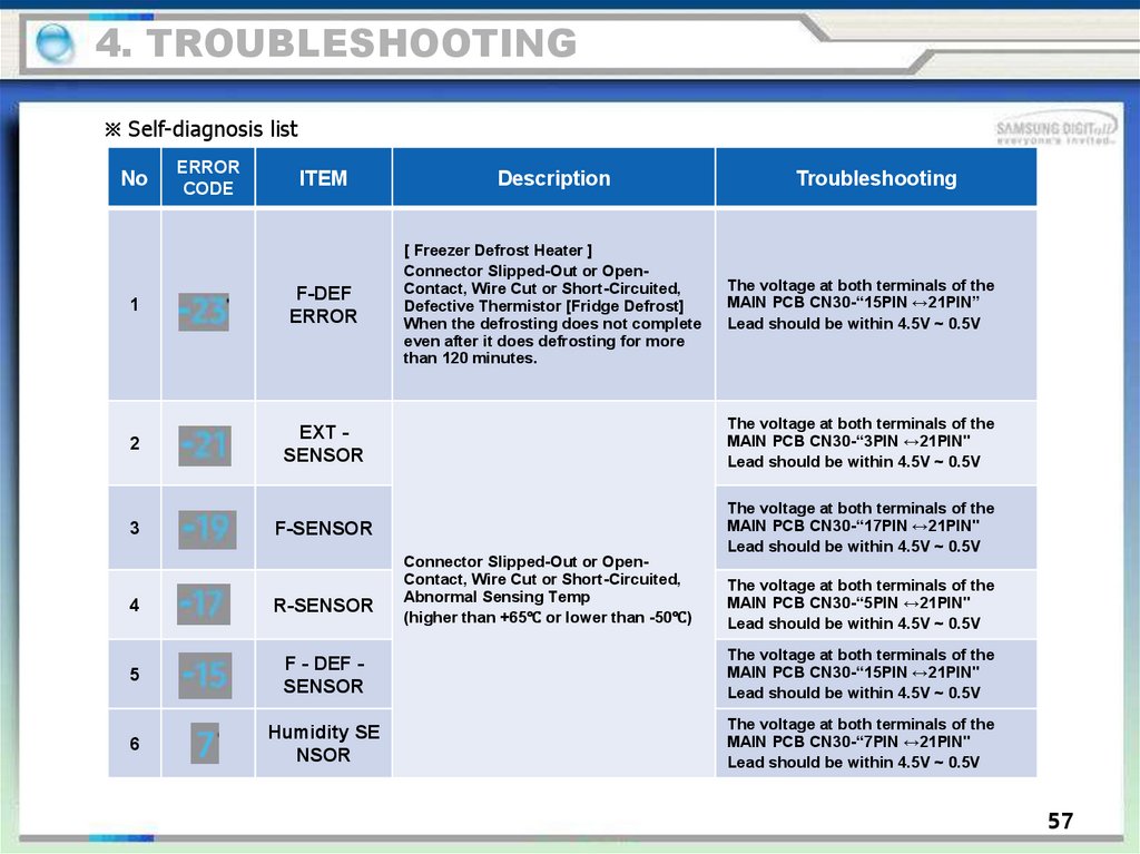
4. TROUBLESHOOTING※ Self-diagnosis list
No
ERROR
CODE
ITEM
Description
1
F-DEF
ERROR
[ Freezer Defrost Heater ]
Connector Slipped-Out or OpenContact, Wire Cut or Short-Circuited,
Defective Thermistor [Fridge Defrost]
When the defrosting does not complete
even after it does defrosting for more
than 120 minutes.
2
EXT SENSOR
The voltage at both terminals of the
MAIN PCB CN30-“3PIN ↔21PIN"
Lead should be within 4.5V ~ 0.5V
3
F-SENSOR
The voltage at both terminals of the
MAIN PCB CN30-“17PIN ↔21PIN"
Lead should be within 4.5V ~ 0.5V
Connector Slipped-Out or OpenContact, Wire Cut or Short-Circuited,
Abnormal Sensing Temp
(higher than +65℃ or lower than -50℃)
Troubleshooting
The voltage at both terminals of the
MAIN PCB CN30-“15PIN ↔21PIN”
Lead should be within 4.5V ~ 0.5V
The voltage at both terminals of the
MAIN PCB CN30-“5PIN ↔21PIN"
Lead should be within 4.5V ~ 0.5V
4
R-SENSOR
5
F - DEF SENSOR
The voltage at both terminals of the
MAIN PCB CN30-“15PIN ↔21PIN"
Lead should be within 4.5V ~ 0.5V
6
Humidity SE
NSOR
The voltage at both terminals of the
MAIN PCB CN30-“7PIN ↔21PIN"
Lead should be within 4.5V ~ 0.5V
57
50.
4. TROUBLESHOOTING※ Self-diagnosis list
No
6
7
Error
Code
Item
Description
Trouble Shooting
F-FAN ERROR
When the related Fan Motor operates,
it occurs if the contact of the Feed
Back Signal Wire is defective, the
Motor Wire is slipped out or the Motor
is defective.
Comp start
failure error
The error code is displayed when the
compressor has failed to start.
COMP IPM
FAULT
ERROR
The error code is displayed when the
compressor IPM fault error has
occurred.
COMP
Abnormal
current
ERROR
The error code is displayed when the
compressor location detection failed.
Check the compressor wire connections.
Check the soldering status of the inverter PCB.
(Check if any parts have short-circuited).
Check the Comp and Cycle.
COMP IPM Mo
dule Close ER
ROR
The error code is displayed when IPM
temperature is over 120°C
Check the input voltage
Check PBA IPM welding status(IPM PIN SHORT
check
COMP Comm
unication ERR
OR
In case of poor communication betwe
en COMP panel and Micom
Check MAIN PCB上PHOTO COUPLER( PC201 ,
202 )parts damage and welding status.
The voltage between MAIN PCB CN76-“3PIN
↔8PIN"should be within 7V~12V
Check the soldering status of the inverter PCB.
(Check if any parts have short-circuited).
Check if the DC 16V output is less than 1 3.5V.
Check the Comp and Cycle.
58
51.
4. TROUBLESHOOTING※ Self-diagnosis list
No
Error
Code
Item
Description
Trouble Shooting
Comp motor
constraint
error
The error code is displayed when the
compressor motor is constrained.
Check if the compressor and the Cycle
is normal. Check the input voltage.
Check the soldering of the inverter
PCB.
(Check if any parts have shortcircuited.)
Comp low
voltage error
The error code is displayed when the
AC Input Voltage is too low.
Check the input voltage. (This error
occurs when the input voltage is AC
106 V or lower.)
Comp over
voltage error
The error code is displayed when the
AC Input Voltage is too high.
Check the input voltage.
(This error occurs when the input
voltage is AC 310V or higher.)
Defrost low re
sistance error
If the Defrost Heater has such status as
housing leakage, poor contact, electric
al short circuit, or fuse ng, Defrosting e
nds in five minutes and will show poor
results.
Check the connection status of MAIN
PCB CN70( AC CONNECTOR )
Check the resistance value between
AC CONNECTOR的#1↔#3 whether is m
easured
8
9
59
52.
4. TROUBLESHOOTING4-1-3. Load Status Display Function
1) During the Normal Operation, press the Freezer + Fridge buttons for 7 seconds. Then, the "2℃,3℃ and 5℃"
Fridge temperature LEDs and the "-17℃,-19℃ and -21℃" Freezer temperature LEDs on the Display Panel will
blink at the interval of 0.5 seconds for 4 seconds.
2) At this time, release the Freezer + Fridge buttons and press the Fridge button (it sends out "Ding Dong“
sound.) Then, it shifts to the Load Display mode.
3) The Load Display function shows what MICOM signals come out from MAIN PCB. But, it just indicates that
there are MICOM signals coming out. It does not necessarily mean that the related parts (Loads) are operating.
In other word, even though it shows a certain load working, the related part may not operate due to such as a
defective PCB relay or the defective part itself (it needs checking).
4) The Load Display function lasts for 30 seconds and then it goes back to the normal operation.
5) The following image shows load locations with the LEDs.
Block B
Block A
①
②
① Press the Freezer + Fridge buttons for 7 seconds at the same time. Then, the Display LEDs will blink for 3
seconds. At this time, release the buttons
② and, press the Fridge button once.
52
53.
4. TROUBLESHOOTING※ Load Mode Check List
No.
Category
Display LED
Description
1
COMP
"-23℃" LED On
LED On when Comp is running
2
F-Defrost HEATER
"-21℃ LED On
LED On when the Freezer Defrost Heater is on
3
R-Damper
"-19℃" LED On
LED On when the Fridge Damper is open.
4
Overload Conditions
"-17℃" LED On
LED On when the ambient temperature is over
34℃
5
Low Temperature
Conditions
"-15℃" LED On
LED On when the ambient temperature is
lower than 23℃
6
Demo Mode
"1℃" LED On
LED On when the unit is on Demo Mode
7
F-Fan High RPM
"2℃" LED On
LED On when the F-Fan runs High
8
F-Fan Low RPM
"3℃" LED On
LED On when the F-Fan runs Low
9
Normal Operating
Conditions
Freezer "-15℃","-17℃"LED Off
When the ambient temperature is between
24℃~33℃
53
54.
4. TROUBLESHOOTING4-1-4. Restoration of Previous Settings upon Instant Power Outage
ON
ON
1) If the Display Panel is initialized by the instant power outage, it will cause customer inquiries. To
prevent this, when the power is restored, the previous settings will be restored or reset based on
the inside temperature of the Freezer Compartment.
2) Upon the initial power on, it checks its Freezer temperature. When it is lower than +10℃, it is to be
considered as an instant power failure and it brings back all its previous operation functions ( such
as Power Freeze, Power Cool, Fridge, Freezer, etc related to the panel display.
3) When it is higher than +10℃, it is to be considered as a long-period power failure and it will
initialize the panel display.(Freezer : Automatically set to -19℃ Fridge : Automatically set to 3℃
54
55.
4. TROUBLESHOOTING4-1-5. Demo Mode Function for Store Display
1) During the Normal Operation, press the Freezer + Fridge buttons for 7 seconds. Then, the "2℃, 3℃ and 5℃"
Fridge temperature LEDs and the "-17℃, -19℃ and -21℃" Freezer temperature LEDs on the Display Panel will blink
at the interval of 0.5 seconds for 3 seconds.
2) At this time, release the Freezer + Fridge buttons and press the Freezer button (it sends out "Ding Dong“ sound.)
Then, it shifts to the Demo mode.
3) During the Demo Mode when the Freezer or Fridge room temperature goes over 65℃ during the Demo Mode, it
will go back to the normal cooling operation.
4) Action items when Demo Mode setting
- When the unit is in Demo Mode, all the functions including the Display Panel works normal. But, theCompressor
does not operate.
- Defrosting does not start.
- Turn off its power to cancel the Demo Mode.
Block B
Block A
②
①
① Press the Freezer + Fridge buttons for 7 seconds at the same time.
② The Display LEDs will blink. At this time, release the buttons and press the Freezer button once.
55
56.
4. TROUBLESHOOTING4-1-6. Option Setting Function
1) During the Normal Operation, press the Freezer + Fridge buttons for 4 seconds.Then, the entire Display Panel will
blink at the interval of 0.5 seconds for 3 seconds.
2) At this time, release the Freezer + Fridge buttons and press the Fridge button (it sends out "Ding Dong" sound.)
Then, it shifts to the Option Setting mode.
● When there is no button press for 20 seconds at the Option Setting Mode, it will go back to the normal display mode.
①
②
① Press the Freezer + Fridge buttons for 4 seconds at the same time.Then, the Display LEDs will
blink for 3 seconds. At this time, release the buttons
② and, press the Fridge button once.
56
57.
4. TROUBLESHOOTING4-1-7. Option Mode & Button Operation Description
②
F-ROOM STEP
①
R-ROOM STEP
④
①
②
③
④
Displays
Displays
OPTION
OPTION
③
the selected Option Set Value
the selected Option #
SET VALUE INCREASE BY ONE DEGREE (Rotation Type)
# INCREASE BY ONE DEGREE (Rotation Type)
57
58.
4. TROUBLESHOOTINGOption Mode & Button Operation Description
● The Bar Type Display Panel shows the numbers as shown in the following tables (Binary Type)
Value
0
1
2
3
4
5
6
7
8
9
10
11
12
13
14
15
1℃
□
□
□
□
□
□
□
□
□
□
□
□
□
□
□
□
-21℃
2℃
□
□
□
□
□
□
□
□
■
■
■
■
■
■
■
■
-19℃
3℃
□
□
□
□
■
■
■
■
□
□
□
□
■
■
■
■
-17℃
5℃
□
□
■
■
□
□
□
■
□
□
■
■
□
□
■
■
-15℃
7℃
□
■
□
■
□
■
□
■
□
■
□
■
□
■
□
■
16
17
18
19
20
21
22
23
24
25
26
27
28
29
30
31
F
R
-23℃
Value
F
R
-23℃
1℃
■
■
■
■
■
■
■
■
■
■
■
■
■
■
■
■
-21℃
2℃
□
□
□
□
□
□
□
□
□
■
■
■
■
■
■
■
-19℃
3℃
□
□
□
■
■
■
■
■
□
□
□
□
■
■
■
■
-17℃
5℃
□
□
■
■
□
□
■
■
□
□
■
■
□
□
■
■
-15℃
7℃
□
■
□
■
□
■
□
■
□
■
□
■
□
■
□
■
58
59.
4. TROUBLESHOOTINGOption Mode & Button Operation Description
● When the Display Panel converts to the Option Setting mode, the entire Display except the Freezer and the
Fridge Temperature LEDs as shown below Temp LED goes off.
Freezer Temp setting
Fridge Temp setting
1) For example, if you want to shift the standard temp of the Freezer compartment by -2℃, follow the steps
below. This function is to change the default temperature and when the default temperature of the Freezer
compartment is -21℃ and the default setting is lowered by -2℃ with the Option function, the default
temperature will be controlled at -23℃. That is, when changing temperature options, the Freezer compartment
will operate at -23℃ internally even if it shows -21℃ on the display panel. Therefore, the temperature will be
controlled by -2℃ lower than the set temperature on the display panel.
Note
Basically, when units being shipped out, all the data in the Option function are cleared. That is, the
Default settings are “0”. However, for the purpose of quality improvement during mass production, the
Default values may change. Therefore, be sure to check quality information, such as SVC bulletins.
2) After changing into the Option mode,“0" on both of the Fridge and Freezer compartments lights up on the display
panel. (when units being shipped out, the unit will be shipped out with "0"s set on both of the Fridge and Freezer
compartments. However, for the purpose of quality improvement during mass production, the Default values may
change
- When the Fridge Display set to the status of the Option #0, it will be set to the Freezer Temperature Option and the
current Freezer Temperature Set Value will be shown on the Freezer Temperature Display(Refer to the Freezer
Temp Shifting Image).
59
60.
4. TROUBLESHOOTINGOption Mode & Button Operation Description
3) When "4" is set as shown in the Freezer Option Table below after setting the Fridge Option # to "0", theFreezer
default temperature will decrease by -2℃. (Refer to the Freezer Temp Shift Figure):In 20 seconds after completing the
adjustment, MICOM is to store the setting value in EEPROM and itgoes back to the normal display mode, deactivating
the Option Setting mode.
4) The Fridge temperature can be adjusted with the same method.
5) Make sure not to change the factory-set default values excluding exceptional circumstances.Also, the Option Setting
will be completed when it goes back to the normal display mode in 20 seconds.So, do not turn off the unit before it
goes back to the normal display mode.
60
61.
4. TROUBLESHOOTING4-1-8. Option TABLE
Notice There are other option setting functions. But, it's got to do with the performance of the unit, not for repair purposes.
So, they are not handled in this manual.(Except those described in this manual, do not change other values)
1) Freezer Temp Shift Table
Setting Item
Option Item
Freezer temp shift
Location Fridge Temp LED
0
Setting Value
Freezer Temp
Display Panel
Set Value
Option Value
0
0℃
1
-0.5℃
2
-1.0℃
3
-1.5℃
4
-2.0℃
5
-2.5℃
6
-3.0℃
7
-3.5℃
8
+0.5℃
9
+1.0℃
10
+1.5℃
11
+2.0℃
12
+2.5℃
13
+3.0℃
14
+3.5℃
15
+4.0℃
옵션번호
-15℃
약
-17℃
약중
-19℃
중
-21℃
중강
-23℃
강
0
1
2
3
4
5
6
7
8
9
10
11
12
13
14
15
16
17
18
19
20
OFF
ON
OFF
ON
OFF
ON
OFF
ON
OFF
ON
OFF
ON
OFF
ON
OFF
ON
OFF
ON
OFF
ON
OFF
OFF
OFF
ON
ON
OFF
OFF
ON
ON
OFF
OFF
ON
ON
OFF
OFF
ON
ON
OFF
OFF
ON
ON
OFF
OFF
OFF
OFF
OFF
ON
ON
ON
ON
OFF
OFF
OFF
OFF
ON
ON
ON
ON
OFF
OFF
OFF
OFF
ON
OFF
OFF
OFF
OFF
OFF
OFF
OFF
OFF
ON
ON
ON
ON
ON
ON
ON
ON
OFF
OFF
OFF
OFF
OFF
OFF
OFF
OFF
OFF
OFF
OFF
OFF
OFF
OFF
OFF
OFF
OFF
OFF
OFF
OFF
OFF
ON
ON
ON
ON
ON
옵션번호
0
1
2
3
4
5
6
7
8
9
10
11
12
13
14
15
16
17
18
19
20
For example, the default temp of freezer is -2.0℃
7℃
약
OFF
ON
OFF
ON
OFF
ON
OFF
ON
OFF
ON
OFF
ON
OFF
ON
OFF
ON
OFF
ON
OFF
ON
OFF
5℃
약약중
3℃
약중
2℃
중
1℃
중강
강
OFF
OFF
ON
ON
OFF
OFF
ON
ON
OFF
OFF
ON
ON
OFF
OFF
ON
ON
OFF
OFF
ON
ON
OFF
OFF
OFF
OFF
OFF
ON
ON
ON
ON
OFF
OFF
OFF
OFF
ON
ON
ON
ON
OFF
OFF
OFF
OFF
ON
OFF
OFF
OFF
OFF
OFF
OFF
OFF
OFF
ON
ON
ON
ON
ON
ON
ON
ON
OFF
OFF
OFF
OFF
OFF
OFF
OFF
OFF
OFF
OFF
OFF
OFF
OFF
OFF
OFF
OFF
OFF
OFF
OFF
OFF
OFF
ON
ON
ON
ON
ON
OFF
OFF
OFF
OFF
OFF
OFF
OFF
OFF
OFF
OFF
OFF
OFF
OFF
OFF
OFF
OFF
OFF
OFF
OFF
OFF
OFF
61
62.
4. TROUBLESHOOTING4-1-8. Option TABLE
2) Fridge Temp Shift Table
Setting Item
Option Item
Freezer temp shift
Location Fridge Temp LED
1
Setting Value
Fridge Temp Di
splay Panel Set
Value
Option Valu
e
0
0℃
1
-0.5℃
2
-1.0℃
3
-1.5℃
4
-2.0℃
5
-2.5℃
6
-3.0℃
7
-3.5℃
8
+0.5℃
9
+1.0℃
10
+1.5℃
11
+2.0℃
12
+2.5℃
13
+3.0℃
14
+3.5℃
15
+4.0℃
옵션번호
-15℃
약
-17℃
약중
-19℃
중
-21℃
중강
0
1
2
3
4
5
6
7
8
9
10
11
12
13
14
15
16
17
18
19
20
OFF
ON
OFF
ON
OFF
ON
OFF
ON
OFF
ON
OFF
ON
OFF
ON
OFF
ON
OFF
ON
OFF
ON
OFF
OFF
OFF
ON
ON
OFF
OFF
ON
ON
OFF
OFF
ON
ON
OFF
OFF
ON
ON
OFF
OFF
ON
ON
OFF
OFF
OFF
OFF
OFF
ON
ON
ON
ON
OFF
OFF
OFF
OFF
ON
ON
ON
ON
OFF
OFF
OFF
OFF
ON
OFF
OFF
OFF
OFF
OFF
OFF
OFF
OFF
ON
ON
ON
ON
ON
ON
ON
ON
OFF
OFF
OFF
OFF
OFF
-23℃
강
OFF
OFF
OFF
OFF
OFF
OFF
OFF
OFF
OFF
OFF
OFF
OFF
OFF
OFF
OFF
OFF
ON
ON
ON
ON
ON
옵션번호
7℃
약
5℃
약약중
3℃
약중
2℃
중
1℃
중강
강
0
1
2
3
4
5
6
7
8
9
10
11
12
13
14
15
16
17
18
19
20
OFF
ON
OFF
ON
OFF
ON
OFF
ON
OFF
ON
OFF
ON
OFF
ON
OFF
ON
OFF
ON
OFF
ON
OFF
OFF
OFF
ON
ON
OFF
OFF
ON
ON
OFF
OFF
ON
ON
OFF
OFF
ON
ON
OFF
OFF
ON
ON
OFF
OFF
OFF
OFF
OFF
ON
ON
ON
ON
OFF
OFF
OFF
OFF
ON
ON
ON
ON
OFF
OFF
OFF
OFF
ON
OFF
OFF
OFF
OFF
OFF
OFF
OFF
OFF
ON
ON
ON
ON
ON
ON
ON
ON
OFF
OFF
OFF
OFF
OFF
OFF
OFF
OFF
OFF
OFF
OFF
OFF
OFF
OFF
OFF
OFF
OFF
OFF
OFF
OFF
OFF
ON
ON
ON
ON
ON
OFF
OFF
OFF
OFF
OFF
OFF
OFF
OFF
OFF
OFF
OFF
OFF
OFF
OFF
OFF
OFF
OFF
OFF
OFF
OFF
OFF
For example, the default temp of fridge is +2.0ºC
62
63.
4. TROUBLESHOOTING4-2. Troubleshooting Flow-Chart by Symptoms
DATA1.Temp Table
Conversion Table - Temperature/MICOM PORT Voltage/Resistance
SENSOR CHIP : PX41C
℃
℉
Voltage
Ω
℃
℉
Voltage
Ω
-50
-58
4.694
153319
-36
-32.8
4.385
71246
-49
-56.2
4.677
144794
-35
-31
4.356
67634
-48
-54.4
4.659
136798
-34
-29.2
4.326
64227
-47
-52.6
4.641
129294
-33
-27.4
4.296
61012
-46
-50.8
4.622
122248
-32
-25.6
4.264
57977
-45
-49
4.602
115631
-31
-23.8
4.232
55112
-44
-47.2
4.581
109413
-30
-22
4.199
52406
-43
-45.4
4.560
103569
-29
-20.2
4.165
49848
-42
-43.6
4.537
98073
-28
-18.4
4.129
47431
-41
-41.8
4.514
92903
-27
-16.6
4.093
45146
-40
-40
4.490
88037
-26
-14.8
4.056
42984
-39
-38.2
4.465
83456
-25
-13
4.018
40938
-38
-36.4
4.439
79142
-24
-11.2
3.980
39002
-37
-34.6
4.412
75077
-23
-9.4
3.940
37169
63
64.
4. TROUBLESHOOTING4-2. Troubleshooting Flow-Chart by Symptoms
℃
℉
Voltage
Ω
℃
℉
Voltage
Ω
-22
-7.6
3.899
35433
-5
23
3.107
16419
-21
-5.8
3.858
33788
-4
24.8
3.057
15731
-20
-4
3.816
32230
-3
26.6
3.006
15076
-19
-2.2
3.773
30752
-2
28.4
2.955
14452
-18
-0.4
3.729
29350
-1
30.2
2.904
13857
-17
1.4
3.685
28021
0
32
2.853
13290
-16
3.2
3.640
26760
1
33.8
2.802
12749
-15
5
3.594
25562
2
35.6
2.751
12233
-14
6.8
3.548
24425
3
37.4
2.700
11741
-13
8.6
3.501
23345
4
39.2
2.649
11271
-12
10.4
3.453
22320
5
41
2.599
10823
-11
12.2
3.405
21345
6
42.8
2.548
10395
-10
14
3.356
20418
7
44.6
2.498
9986
-9
15.8
3.307
19537
8
46.4
2.449
9596
-8
17.6
3.258
18698
9
48.2
2.399
9223
-7
19.4
3.208
17901
10
50
2.350
8867
-6
21.2
3.158
17142
11
51.8
2.301
8526
64
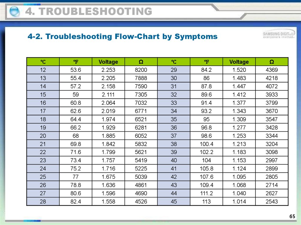
65.
4. TROUBLESHOOTING4-2. Troubleshooting Flow-Chart by Symptoms
℃
℉
Voltage
Ω
℃
℉
Voltage
Ω
12
53.6
2.253
8200
29
84.2
1.520
4369
13
55.4
2.205
7888
30
86
1.483
4218
14
57.2
2.158
7590
31
87.8
1.447
4072
15
59
2.111
7305
32
89.6
1.412
3933
16
60.8
2.064
7032
33
91.4
1.377
3799
17
62.6
2.019
6771
34
93.2
1.343
3670
18
64.4
1.974
6521
35
95
1.309
3547
19
66.2
1.929
6281
36
96.8
1.277
3428
20
68
1.885
6052
37
98.6
1.253
3344
21
69.8
1.842
5832
38
100.4
1.213
3204
22
71.6
1.799
5621
39
102.2
1.183
3098
23
73.4
1.757
5419
40
104
1.153
2997
24
75.2
1.716
5225
41
105.8
1.124
2899
25
77
1.675
5039
42
107.6
1.095
2805
26
78.8
1.636
4861
43
109.4
1.068
2714
27
80.6
1.596
4690
44
111.2
1.040
2627
28
82.4
1.558
4526
45
113
1.014
2543
65
66.
4. TROUBLESHOOTING4-2. Troubleshooting Flow-Chart by Symptoms
℃
46
47
48
49
50
51
52
53
54
55
56
57
58
59
60
61
62
63
64
65
℉
114.8
116.6
118.4
120.2
122
123.8
125.6
127.4
129.2
131
132.8
134.6
136.4
138.2
140
141.8
143.6
145.4
147.2
149
Voltage
0.988
0.963
0.938
0.914
0.891
0.868
0.846
0.824
0.803
0.783
0.762
0.743
0.724
0.706
0.688
0.670
0.653
0.636
0.620
0.604
Ω
2462
2384
2309
2237
2167
2100
2036
1973
1913
1855
1799
1745
1693
1642
1594
1547
1502
1458
1416
1375
℃
66
67
68
69
70
71
72
73
74
75
76
77
78
79
80
81
82
83
84
℉
150.8
152.6
154.4
156.2
158
159.8
161.6
163.4
165.2
167
168.8
170.6
172.4
174.2
176
177.8
179.6
181.4
183.2
Voltage
0.598
0.574
0.560
0.546
0.532
0.519
0.506
0.493
0.481
0.469
0.457
0.446
0.435
0.424
0.414
0.404
0.394
0.384
0.375
Ω
1335
1297
1260
1225
1190
1157
1125
1093
1063
1034
1006
978
952
926
902
877
854
832
810
66
67.
4. TROUBLESHOOTING4-2-1. When Self-Diagnosis Error occurs
- The Display Panel shows the Sensor Error and, when the unit is plugged in and there are sensor errors, the
unit does not operate and LED related to the defective sensors keep blinking.
- When sensor defects occur during the operation, the unit keeps working. But, it shifts to the Emergency
Operation and it may not work properly. So, please check the unit according to the Self Diagnosis function.
1) When the R-Sensor is defective
ERROR CODE
67
68.
4. TROUBLESHOOTING4-2-1. When Self-Diagnosis Error occurs
2) When the EXT Sensor is defective
ERROR CODE
69
69.
4. TROUBLESHOOTING4-2-1. When Self-Diagnosis Error occurs
3) When the F-Sensor is defective
ERROR CODE
69
70.
4. TROUBLESHOOTING4-2-1. When Self-Diagnosis Error occurs
4) When the DEF-Sensor is defective
ERROR CODE
70
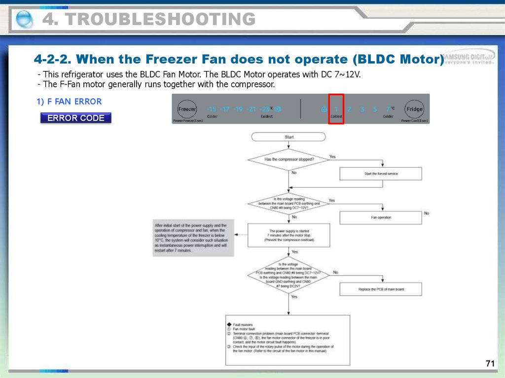
71.
4. TROUBLESHOOTING4-2-2. When the Freezer Fan does not operate (BLDC Motor)
- This refrigerator uses the BLDC Fan Motor. The BLDC Motor operates with DC 7~12V.
- The F-Fan motor generally runs together with the compressor.
1) F FAN ERROR
ERROR CODE
71
72.
4. TROUBLESHOOTING4-2-3. When Defrost does not work (F DEF Heater)
ERROR CODE
72
73.
4. TROUBLESHOOTING4-2-3. When Defrost does not work (F DEF Heater)
ERROR CODE
73
74.
4. TROUBLESHOOTING4-2-4. When there is No Power (MAIN PBA)
74
75.
4. TROUBLESHOOTING4-2-4. When there is No Power (MAIN PBA)
75
76.
4. TROUBLESHOOTING4-2-5 When the unit keeps alarming (Buzzer Sound)
Reference 1. Fridge / Freezer Door Open Alarm : It sends out an alarm sound when it passes over 2 minutes after the
door is open. And, when the door remains open, it will keeps alarming every minute.
2. When the door is not closed properly, MICOM recognizes it as Door Open and sends out an alarm sound.
When it passes over 10 minutes after it recognizes the Door Open, the room lamps will be off. At this time,
when the Door is completely open, the Lamp will not be on right away, but after a while.
① When there is "Ding Dong" sound not stopping
76
77.
4. TROUBLESHOOTING4-2-5 When the unit keeps alarming (Buzzer Sound)
② When it keeps 'Beeping
77
78.
4. TROUBLESHOOTING4-2-5 When the unit keeps alarming (Buzzer Sound)
③ No Buzzer Sound
This model has a buzzer affixed on the MAIN PCB.
If there is no buzzer sound upon button press, Forced Operation or Door Open, disconnect MAIN PCB and check if the buzzer is damaged
or there is any defective soldering.
(If it is not a soldering problem, it is recommended replacing MAIN PCB due to difficulties in repairing)
※ It may not be able to check when it is a closed built-in environment and there is lots of noise around.
78
79.
4. TROUBLESHOOTING4-2-6. When PANEL PCB operates abnormally
① When PANEL PCB does not light up or partially does
79
80.
4. TROUBLESHOOTING4-2-6. When PANEL PCB operates abnormally
80
81.
4. TROUBLESHOOTING4-2-7. When the Room Lamp (LED) does not light up
81
82.
4. TROUBLESHOOTING4-2-8. When Fridge Damper does not work
82
83.
4. TROUBLESHOOTINGLED blinking frequency depending on protecting functions (Inverter PBA)
If Failure Condition is detected during compressor is operating, immediately stop Compressor operating and stand by 5
minutes. During this 5 minutes, RPM command signal is not available. It means, even if available RPM command signal is
applied to the compressor, it does not work and keep standing by.
Blinking time is 1 second and dwell time is 1 seconds.
Description
Normal Operation
Starting Failure
SPM Fault
LED Blinking Frequency
Remarks
N/A
1.Check the COMP terminals short (U,V,W)
2.Check IPM Pins short of Inverter PBA
3.Check IPM operating Voltage (under DC 13.5V)
4.Other cases, check the COMP, cycle, etc.
Position Sensing Error
1.Check COMP wire connections (U,V,W)
2.Check PBA Bottom side soldering state
3.Other cases, check the COMP, cycle, etc.
Motor Locked / Over
RPM
1.Check PBA Bottom side soldering state.
2.Check Input voltage oscillation
3.Other cases, check the COMP, cycle, etc.
Under Voltage
1. Check input voltageNormal Operating Voltage
Range(AC 220V ~ 240V)
2.Check PBA Bottom side soldering state.
Over Voltage
1. Check input voltageNormal Operating Voltage
Range(AC 220V ~ 240V)
2.Check PBA Bottom side soldering state.
LED blinking frequency depending on protecting functions If the same blinking, After 5 minutes, Follow the Remarks.
83
84.
5. PCB/PBA DIAGRAM5-1. PART Layout (Main Board)
5
3
4
6
8
7
2
1. Inverter COMP. Signal Section
2.EEPROM:Storing/Writing various data
3. Relay Section controls the AC Load
4. MAIN → PANEL PCB Operation Control
Sensor and Door Switch signal circuit
5.Fan Motor and Buzzer circuit
6.Main MICOM
7.Damper circuit
8.Filter circuit and Power conversion
circuit
1
84
85.
5. PCB/PBA DIAGRAM5-2. Connector Layout & Description (Main Board)
119
86.
6. WIRING DIAGRAM6. Wiring diagram
삼성의 허가 없이 문서 활용 불가
86
87.
7. BLOCK DIAGRAM7-1. PBA Main
This document can not be used without Samsung's authorization
87
88.
8. CYCLECondenser (Option)
87
89.
9. Sensor layoutHumidity Sensor
(COVER CONTROL)
Fridge Temp Sensor
(REF COVER DUCT)
Freezer Temp Sensor
(FRE COVER DUCT)
F-Defrost Sensor
(ASSY EVAP)
88
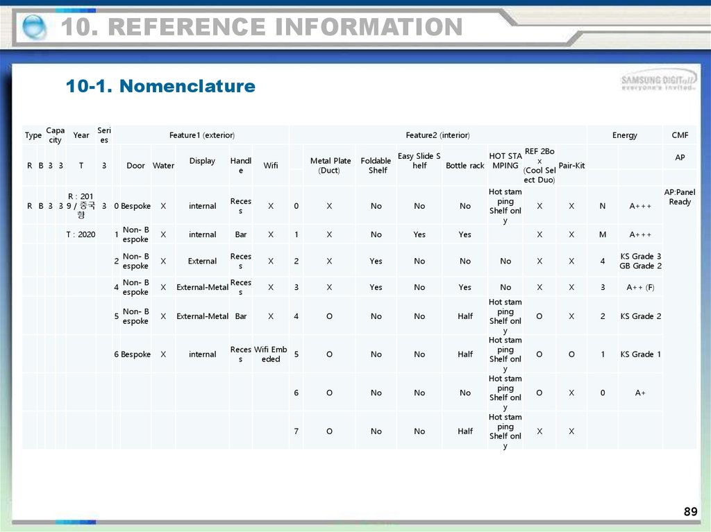
90.
10. REFERENCE INFORMATION10-1. Nomenclature
Type
Capa
city
R B 3 3
Year
Seri
es
T
3
Feature1 (exterior)
Door Water
Display
Feature2 (interior)
Handl
e
Wifi
Metal Plate
(Duct)
Foldable
Shelf
Easy Slide S
HOT STA
helf
Bottle rack MPING
R : 201
R B 3 3 9 / 중국 3 0 Bespoke
향
X
internal
Reces
s
X
0
X
No
No
No
1
Non- B
espoke
X
internal
Bar
X
1
X
No
Yes
Yes
2
Non- B
espoke
X
External
Reces
s
X
2
X
Yes
No
No
4
Non- B
espoke
X
External-Metal
Reces
s
X
3
X
Yes
No
Yes
5
Non- B
espoke
X
External-Metal Bar
X
4
O
No
No
Half
6 Bespoke
X
Reces Wifi Emb
5
s
eded
O
No
No
Half
6
O
No
No
No
7
O
No
No
Half
T : 2020
internal
Energy
Hot stam
ping
Shelf onl
y
REF 2Bo
x
Pair-Kit
(Cool Sel
ect Duo)
AP
X
X
N
A+++
X
X
M
A+++
No
X
X
4
KS Grade 3
GB Grade 2
No
X
X
3
A++ (F)
O
X
2
KS Grade 2
O
O
1
KS Grade 1
O
X
0
A+
X
X
Hot stam
ping
Shelf onl
y
Hot stam
ping
Shelf onl
y
Hot stam
ping
Shelf onl
y
Hot stam
ping
Shelf onl
y
CMF
AP:Panel
Ready
89
91.
Thank you- This Service Manual is a property of Samsung Electronics Co., Ltd.
Any unauthorized use of Manual can be punished under applicable
International or domestic law.