


 Промышленность
Похожие презентации:


Bottom mounted freezer type
1.
BOTTOM MOUNTED FREEZER TYPEBASIC MODEL : RL55VE*
MODEL NAME : R
L55VE*/Q*/T*/S*/J*
RL52VE*/S*/W*
RL55TE*/Q*/T*/S*/J*
RL57TE*/Q*/T*/S*/J*
RL52TE*/S*/W*
REFRIGERATOR
RL55VE*/S*/J*
RL52VE*/S*
RL55TE*/S*/J*
RL57TE*/S*/J*
RL52TE*/S*
RL55VQ*
RL55TQ*
RL57TQ*
RL55VT*
RL55TT*
RL57TT*
PRODUCT FEATURE
RL52VW*
RL52TW*
High Efficiency A++, A+
CoolSelect Zone™
7 Inch Touch LCD Display
Handle Lighting
2.
WARNINGIMPORTANT SAFETY NOTICE
The service guide is for service men with adequate backgrounds of
electrical, electronic, and mechanical experience. Any attempt to
repair a major appliance may result in personal injury and property
damage. The manufacturer or dealer cannot be responsible for the
interpretation of this information.
SAMSUNG ELECTRONICS AMERICA, INC.
Technical Service Guide
Copyright ©2009
ll rights reserved. This service guide may not be reproduced in whole or in part in
A
any form without written permission from the SAMSUNG ELECTRONICS Company.
3.
Contents1. PRECAUTIONS (SAFETY WARNINGS)·········································································4
2. PRODUCT SPECIFICATIONS························································································7
3. DISASSEMBLY AND REASSEMBLY············································································14
4. TROUBLE SHOOTING·································································································38
5. PCB DAIGRAM···········································································································162
6. WIRING DIAGRAM·····································································································169
7. CIRCUIT DIAGRAM····································································································175
3
4.
1. PRECAUTIONS (SAFETY WARNINGS)●B
efore attempting a repair of any kind ensure that the appliance is disconnected from the mains electricity
supply.
● Use rated electronic Control equipment.
Make sure to check out ModeL name, Rated voltage, Rated current, Operation Temp, etc.
● Take care not to use excessive force and damage any wiring connectors when disconnecting/reconnecting.
Also ensure that the wiring connectors are placed in their original position and not subject to water
penetration.
●U
pon repair, completely remove dust or other foreign substances from housing, harness, connector, etc.
To prevent fire by tracking, short, etc.
● Check the electronic control system for signs of water damage.
I f there is any kind of trace, take necessary measures such as related component change, insulation
tapping, etc.
● After repair, check out the assembled state of parts.
It should be the same as the original state.
● Check the surrounding conditions.
C
hange the location, if the fridge is located at humid, wet places or the installed state is unstable.
● If needed, ground the fridge.
Especially, if there is a possibility of electric leakage, ground is indispensable.
● Advise the consumer if electrical sockets are overloaded.
●C
heck whether the power cord or the outlet is broken, squeezed, chopped off or heat-deformed.
Replace the power cord/outlet if it is damaged in any way.
● Do not allow consumers to keep food unstable or place bottles in the Freezer Room.
● Do not allow consumers to repair the fridge for themselves.
● Do not allow consumers to keep things except for food.
P
harmaceutical, Chemical substances : These are not possible to be fine-Controlled with a consumer
fridge.
Flammable material (alcohol, benzene, ether, LPG, etc) : possibility of explosion.
4
5.
PRECAUTIONS(SAFETY WARNINGS)Read all instructions before repairing the product and keep to the instructions
in order to prevent danger or property damage.
CAUTION/WARNING SYMBOLS DISPLAYED
Warning
Caution
SYMBOLS
means Prohibition”.
Indicates that a
danger of death
or serious injury
exists.
means Do not disassemble”.
means No contact”.
means The things to
be followed”.
Indicates that a risk
of personal injury
or material damage
exists.
means Power cord should be
unplugged from the consent”
means Earth to prevent Electric
shock”.
Warning & Caution
Pull the power plug out to exchange
the interior lamp of the refrigerator.
● It may cause electric shock.
Use the rated components on the
replacement.
●C
heck the correct model, rated voltage, rated
current, operating temperature and so on.
On repair, make sure that the wires
such as harness are bundled tightly.
●B
undle tightly wires in order not to be
detached by the external force and then not to
be wetted.
comRated
pone
nts
Unplug
On repair, remove completely dust
or other things of housing parts,
harness parts, and check parts.
●C
leaning may prevent the possible fire by
tracking or short.
After repair, check the assembled
state of components.
● I t must be in the same assembled state when
compared with the state before disassembly.
5
Check if there is any trace indicating
the permeation of water.
● I f there is that kind of trace, change the related
components or do the necessary treatment
such as taping using the insulating tape.
6.
PRECAUTIONS(SAFETY WARNINGS)❈ Please let users know following warnings & cautions in detail.
Warning & Caution
Do not allow users to put bottles or
glass in the freezer.
● Freezing of the contents may inflict a wound.
Prohibition
Do not allow users to insert the power
plugs for many products at the same
time.
● May cause abnormal generation of heat or fire.
Prohibition
Do not allow users to store articles on
the product.
Do not allow users to store narrow and Do not allow users to store materials,
lengthy bottles or foods in a small
etc., in the refrigerator.
multi-purpose room.
●T
he products which temperature control should
● I t may hurt you when refrigerator door is opened
and closed resulting in falling stuff down.
Prohibition
not be stored in the refrigerator.
Prohibition
Do not allow users to disassemble,
repair or alter.
Do not allow users to bend the power
cord with excessive force or do not have
the power cord pressed by heavy article.
● I t may cause fire or abnormal operation which
leads to injury.
● May cause fire.
Do not
disassemble
Do not allow users to install the
refrigerator in the wet place or the
place which water splashes.
●O
pening or closing the door may cause things to
●D
eterioration of insulation of electric parts may
fall down, with may inflict a wound.
cause electric shock or fire.
Prohibition
Make sure of the earth.
● I f earthing is not done, it will cause breakdown
and electric shock.
Earth
6
7.
2. PRODUCT SPECIFICATIONS2-1. INTRODUCTION OF MAIN FUNCTION··································································8
2-2. MODEL SPECIFICATION························································································9
2-3. ELECTRIC PARTS SPECIFICATION····································································11
2-4. DIMENSIONS (MM)·······························································································13
7
8.
PRODUCT SPECIFICATIONS2-1) Introduction of main function
SAMSUNG refrigerator has the following characteristics.
Characteristics
Specification
• This products protects the environment by using the R600a refrigerant
and the cyclopentane blowing agent.
Environment-friendly
fridge/freezer using R600a • Properties :ODP(Ozone Depletion Potential):0GWP :Lowest
* GWP(Global Warming Potential)
High -energy efficiency
(A++, A+)
• Optimized power consumption when using R600a and cyclopentane.
• Help to preserve the taste of food and prolong its freshness.
• Use this space to store cheese, meat, poultry, fish or any other foods.
Store specific foods at
various temperature
conditions.
Fridge at the top,
drawer-type freezer
at the bottom
• The highly ergonomic vegetables compartment is placed at waist height
as it is frequently used.
• The drawer -type freezer minimize temperature variations and stores food
cleanly and conveniently.
7 inch LCD Display
or Digital display
• 7 inch LCD provides you various information such
as photo slide show, memo, etc.
• The digital display shows all functions of the
appliance, so that you can easily control them.
Supply of cool water
without door opening
• With the water dispenser,you can obtain chilled water easily
without opening the door. In addition, you can save electricty by
more than 30% reducing the number of times the door is open.
SUPER fast freezing
function
• Food can be stored in fresh conditions by cooling it
quickly via the "Power Freeze" freezing function.
Vacation
• Save on energy consumption by switching off the fridge
and maintaining only the freezer when you take a long
vacation or are away for any reason.
8
9.
PRODUCT SPECIFICATIONS2-2) Model Specification
Item
Specification
Model
Net
Capacity
Gross
Capacity
(ISO 15502)
Net
Dimension
*/XSH,
*/BWT,
Total */HAC
other
countries
Refrigerator
RL57TT*
RL57TQ*
RL57TJ*
RL57TE*
RL57TS*
RL55TT*
RL55TQ*
RL55TJ*
RL55TE*
RL55TS*
RL52TS*
RL55VT*
RL55VQ*
RL55VJ*
RL55VE*
RL55VS*
RL52VS*
RL52VE*
RL52VW*
RL52TE*
RL52TW*
328L
328L
348L
348L
350L
330L
328L
320L
324L
316L
324L
324L
344L
344L
346L
326L
324L
316L
320L
310L
232L
232L
252L
252L
254L
234L
232L
224L
232L
224L
*/XSH,
*/BWT,
Freezer */HAC
other
countries
96L
96L
96L
92L
92L
92L
Total
348L
348L
367L
367L
367L
347L
347L
339L
347L
339L
Refrigerator
237L
237L
256L
256L
256L
236L
236L
228L
236L
228L
73kg
75kg
Freezer
111L
W(mm)
600
D(mm)
646
H(mm)
2000
Rated Voltage and
Frequency
1920
220 ~ 240V / 50Hz
110 ~ 127V / 60HZ : (Only for */PEC)
Motor Rated
Consumption Power
80 ~ 95 W
Electric Heater Rated
Consumption Power
240W ~ 288W
Kind of Refrigerator
INDIRECT COOLING METHOD REFRIGERATOR
Refrigerant /
Refrigerant Amount
R600a / 60g or R134a / 145g
Freezer Performance
Product Weight
4 -STAR
88kg
79kg
75kg
75kg
9
73.5kg
73kg
75kg
10.
PRODUCT SPECIFICATIONSNOTE
This operation instruction covers various
models.
The characteristics of your appliance
may differ slightly from those described
in this manual.
10
11.
Components for FreezerElectric Components
RL55VJ*
RL55TJ*
RL57TJ*
RL52VS*
4-STAR
RL52VE*
RL52TS*
11
DC 12V / 3W(10EA)
LED Type
LED Type
Interior Lamp
Exterior Lamp
Door Switch
-
IS-27210SNC5B
-
AC
DC 12V / 1.2W(4EA)
-
DREP5020LB
-
Reed Switch
DC 12V / 1.2W(4EA)
-
DC 12V / 1.5W(5EA)
DREP5020LB
DC 12V / 1.2W(4EA)
110 ~ 127V/60Hz
220 ~ 240V / 50Hz
DC 12V /
3W(10EA)
-
DREP5020LB
69 ±9℃
4TM445PHBYY-82
61±9℃
IS-27210SNC5B
FREOL α-10 (ESTER)
Temp. OFF
-
RL52TW*
125 ± 5℃
BLDC
Motor
R134a
RL52TE*
MSV162AL1J/E01
RL52VW*
130±5℃
4TM308RFBYY-82
AC 250V / 10A / 77℃ (+0℃ / -5℃)
240W
RL52VE*
RL55TT*
Temp. ON
Rated Voltage
Over-load
Relay
Model
Thermal-Fuse for preventing
overheating of Refrigerator DefrostHeater
Conducting
at F Defros
ID 0.75 x L3500, 5.95kg/㎠
Capillary Tube
Defrost
Heater
Molecular Sieve XH-9
Split Fin Type
BLDC
MSV4A1AL1J/E01
RL52VW*
RL55VE*
Dryer
DREP5020LB
Mineral Oil (10 cst)
MSV4A1AL1B/
E01
R600a
RL55VS*
RL55TS*
RL57TS*
Natural Convection Type
Freezer
Oil Charge
Starting type
RL55VQ*
RL55VT*
RL55TE*
RL57TE*
MSV4A1AL1J/E01
RL55TQ*
RL57TQ*
RL55TT*
RL57TT*
Specification
Condenser
Evaporator
Compressor
Model
Freezing Capacity
Refrigerant
Models
Item
PRODUCT SPECIFICATIONS
2-3) Electric Parts Specification
12.
ItemsSpecification
Model
RL55 / RL52
Refrigerator
Freezer
Model
Defrost Cycle
Defrost Related Components Room Temperature Sensor Components
PRODUCT SPECIFICATIONS
Temperature Selection
ON(°C)
OFF(°C)
-23°C
-24.0
-22.0
-20°C
-19.0
-21.0
-14°C
-13.0
-15.0
Temperature Selection
ON(°C)
OFF(°C)
1°C
2.0
0
3°C
4.0
2.0
7°C
8.0
6.0
THERMISTOR
(Freezer sensor)
502AT
Model
THERMISTOR
(Fridge sensor)
502AT
First Defrost Cycle (Concurrent defrost of F and F)
6hr ±10min
Defrost Cycle(FRE)
6 ~ 53hr (vary according to the conditions used)
Pause time
8 ±1 min
Defrost Sensor
Thermal-Fuse
Model
Thermister(502AT)
SPEC
5.0KΩ at 25 °C
Rated
AC 250V 10A
Operating temperature
77 °C (+0 °C/-5 °C)
12
13.
PRODUCT SPECIFICATIONS2-4) Dimensions (mm)
646
2000 (RL55* / RL57*) or 1920 (RL52*)
50
590
1164.5
600
560
13
14.
3. DISASSEMBLY & REASSEMBLY3-1) PRECAUTION··········································································································· 15
3-2) ASSY DOOR ·············································································································16
REMOVING THE REFRIGERATOR DOOR ······························································16
REMOVING THE FREEZER DOOR ·········································································17
3-3) DOOR SUB PARTS ··································································································18
3-4) REFRIGERATOR COMPARTMENTS ·······································································23
3-5) FREEZER COMPARTMENTS ··················································································28
3-6) MACHINE COMPARTMENTS ··················································································29
3-7) REVERSING THE DOOR SWING ············································································30
3-8) RELAY PROTECTOR O/L ························································································38
14
15.
DISASSEMBLY & REASSEMBLY3-1) PRECAUTION
• Unplug the refrigerator before cleaning and making repairs.
• Do not dissemble or repair the refrigerator by yourself.
- You run risk of causing a fire, malfunction and/or personal injury.
• Remove any foreign matter or dust from the power plug pins.
- Otherwise there is a risk of fire.
• Do not use a cord that shows cracks or abrasion damage along its length or at either end.
• Do not plug several appliances into the same multiple power board. The refrigerator should always
be plugged into its own individual electrical which has a voltage rating that matched the rating plate.
- This provides the best performance and also prevents overloading house wiring circuits, which
could cause a fire hazard from overheated wires.
• Do not install the refrigerator in a damp place or place where it may come in contact with water.
- Deteriorated insulation of electrical parts may cause an electric shock or fire.
• The refrigerator must be grounded.
- You must ground the refrigerator to prevent any power leakages or electric shocks caused by
current leakage from the refrigerator.
• Do not put bottles or glass containers in the freezer.
- When the contents freeze, the glass may break and cause personal injury.
• Do not store volatile or flammable substances in the refrigerator.
- The storage of benzene, thinner, alcohol, ether, LP gas and other such products may cause
explosions.
- NEED TOOL
IMAGE
ITEM
USE
Phillips Head Driver
Use for assembling and
disassembling of screws
Flat Head Driver
Use for assembling and
disassembling
of HomeBar, Dispenser, Deli
Cartessen Box, Main PBA etc...
11mm Wrench
Use for assembling and
disassembling of Hinge
Socket Wrench Ø10mm
Use for assembling and
disassembling of Door Hinge
15
16.
DISASSEMBLY & REASSEMBLY3-2) Assy Door
Removing the Refrigerator Door
PART NAME
FIGURE
DESCRIPTION
1) With the door closed, remove 4 screws on
the top of the refrigerator and disconnect
the wire underneath the Cap Cabi (①),
then take off the Cap Cabi(①).
①
Be careful of injury.
Ensure that the appliance is
disconnected from the electricity
supply before starting this
procedure.
Removig
the
Refrigerator
Door
2) Disconnect the wire and then remove 3
bolts(②) on the top of the refrigerator. And
then disassemble the Fridge door(③) by
carefully lifting the door straight up.
Make sure the Fridge door is
closed firmly. Fridge door is
heavy, be careful not to injure
yourself and not to scratch when
removing the Fridge door.
②
③
16
17.
DISASSEMBLY & REASSEMBLYRemoving the Freezer Door
PART NAME
FIGURE
DESCRIPTION
1) Open the Freezer door and disassemble
the Front Leg Cover(①) by removing 2
screws.
Removig
the
Refrigerator
Door
①
Be careful not to scratch the
cabinet.
②
2) Remove 2 bolts securing the Assy Hinge
Low(②).
Before removing the Assy Hinge
Low, slightly turn the front leg
clockwise for easier disassembling.
2) Take off the Freezer door(③) and the Assy
Hinge Low(②) together.
③
Take care when removing the
door to ensure that it does not fall
on you.
- If you want to reassemble, follow the
instruction in reverse order.
17
18.
DISASSEMBLY & REASSEMBLY3-3) Door Sub parts
PART NAME
FIGURE
DESCRIPTION
- 7 Inch LCD Type
1. Insert a flat-head screwdriver on the slot
as shown, and unlock the tabs.
2. Disconnect the wire connector.
When diassembling, make sure
the unit turned off.
- Trim Kit Type
1. Disassemble the Wire Cap Door by
removing a screw on the top of the Fridge
door.
2. Take out display upper direction.
3. Disconnect the wires.
Removing
the
Refrigerator
Door
When diassembling, make sure
the unit turned off.
- Plate Type
1. Insert a flat-head screwdriver on the
slot as shown, and unlock the tabs.
2. Disconnect the wire connector.
18
19.
DISASSEMBLY & REASSEMBLYPART NAME
FIGURE
DESCRIPTION
1. Remove 2 screws underneath the Fridge
door. And then take off 2 Cap sheets and
remove 2 screws on the Freezer door.
Door Handle
Type A
2. Slightly push down the Fridge handle and
then remove it by pulling it toward to you.
Slightly push up the Freezer handle and
then remove it by pulling it toward to you.
Be careful not to break hook
inside of Door Handles, when you
disassemble them.
1. Remove 2 screws underneath the Fridge
door and then pull the Cover Handle
forward to you.
Be careful not to break hooks
inside of Cover Handle, when you
disassemble it.
COVER HANDLE
Door Handle
Type B
HANDLE EASY
2. Disassemble the Handle Easy, after
removing 3 screws and the Grommet
Handles both side of the Fridge door.
GROMMET
SLIDER HANDLE
3. Remove Slider Handle and the Spring.
SPRING
19
20.
DISASSEMBLY & REASSEMBLYPART NAME
FIGURE
DESCRIPTION
1. Remove 2 screws underneath the Fridge
door and then pull the Cover Handle
forward to you.
COVER HANDLE
HANDLE EASY
2. Disassemble the Handle Easy, after
removing 3 screws and the Grommet
Handles both side of the Fridge door.
GROMMET
Handle
Lighting
(Glass)
Be careful not to break hooks
inside of Cover Handle. When you
disassemble it.
Cover Lamp
3. Disassemble Cover Lamp after removing
2 screws on the Fridge door.
4. Take out the LED lamp.
5. Disconnect the wire.
When diassembling, make sure
the unit turned off.
20
21.
DISASSEMBLY & REASSEMBLYPART NAME
FIGURE
DESCRIPTION
Cover Lamp
1. Disassemble Cover Lamp after removing 2
screws underneath the Fridge door.
2. Take out the LED lamp and then
disconnect the wire.
Handle
Lighting
(Plate Door)
When diassembling, make sure
the unit turned off.
The door gasket is a molded gasket set into
a channel located in the door liner.
1. Open the door.
2. Grasp the gasket and pull in an outward
motion until the molded gasket separates
from the door liner.
Door Gaskets
(Fridge/
Freezer)
Be careful of injury.
The refrigerator has a door magnet
switch located in the upper center for the
refrigerator.
Fridge Door
Magnet S/W
1. U
se a small flat-blade screwdriver to unlock
the locking tab and pull the switch out.
The refrigerator has door reed switches.
Reed switch for the fridge door is located
under the cap cabi. Reed switch for the
freezer door is located underneath the fridge
door.
Fridge/
Freezer
Door Reed
S/W
1. Use a small flat-head screwdriver to unlock
the reed switches and pull the switches
out.
21
22.
DISASSEMBLY & REASSEMBLYPART NAME
FIGURE
DESCRIPTION
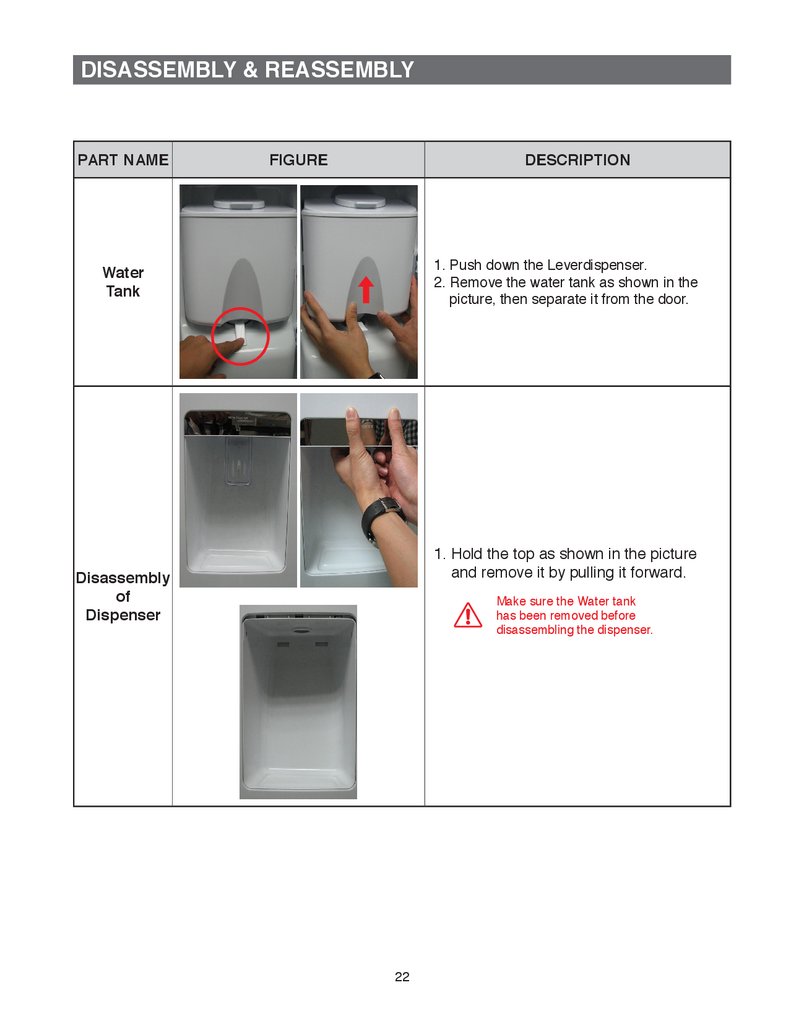
1. Push down the Leverdispenser.
2. Remove the water tank as shown in the
picture, then separate it from the door.
Water
Tank
1. H
old the top as shown in the picture
and remove it by pulling it forward.
Disassembly
of
Dispenser
Make sure the Water tank
has been removed before
disassembling the dispenser.
22
23.
DISASSEMBLY & REASSEMBLY3-4) Refrigerator Compartments
PART NAME
FIGURE
DESCRIPTION
These shelves allow the storage of larger
items and pull out for easy access.
Glass
Shelf
1. Lift it up and pull the shelf out to the front.
Drawers are designed for storage of
fruits,vegetables,and deli items.The drawers
are located in the lower portion of the
refrigerator.
Plastlc
Drawers
In
Refrlgerator
1. Pull out the drawer as far as it goes.
2. Tilt the drawer up and pull it out until it is
removed.
1. Remove 2 screws and pull the CoolSelect
Zone drawer out and then disconnect the 2
wire connectors.
Cool
Select
Zone™
When diassembling, make sure
the unit turned off.
1. Pull the Cooler Zone drawer out.
2. Push the hooks under the Cover Chilled
High to disassemble the Cover Chilled
High.
COOLER
ZONE
23
24.
DISASSEMBLY & REASSEMBLYPART NAME
FIGURE
DESCRIPTION
The refrigerator lights are located in the
Refrigerator.
1. Remove all shelves, plastic drawer and
CoolSelect Zone drawer.
2. Pull out cover lamp after removing 1 screw
as shown.
3. Remove 3 screws as shown and disconnect
the upper and lower wire connectors.
When diassembling, make sure
the unit turned off.
Refrigerator
Light
(Type Ⅰ)
4. Remove tape for cover of wire at the back
side and remove 3 screws at the front side.
24
25.
DISASSEMBLY & REASSEMBLYPART NAME
FIGURE
DESCRIPTION
The Refrigerator lights are located in the
Refrigerator.
1. Disassemble Cover Lamp by pushing
hooks.
2. Take out the LED lamp and then disconnet
the wire.
Refrigerator
Light
(Type Ⅱ)
When diassembling, make sure
the unit turned off.
- Type Ⅰ
The refrigerator thermistor is located inside of
the light cover of the refrigerator.
Refrigerator
Thermistor
- Type Ⅱ
The refrigerator thermistor is located inside
the refrigerator.
25
26.
DISASSEMBLY & REASSEMBLYPART NAME
FIGURE
DESCRIPTION
The CoolSelect Zone™ thermistor is located
inside the back of CoolSelect Zone™
drawer.
The temperature signal is sent to the
microprocessor.
Cool Select
Zone™
Thermistor
Dairy Bin
Door Bin
The door bins allow storage of perishable
items.
Variety
1.Push the bin up and slide it out .
Bottle Bin
Kids
26
27.
DISASSEMBLY & REASSEMBLYPART NAME
FIGURE
DESCRIPTION
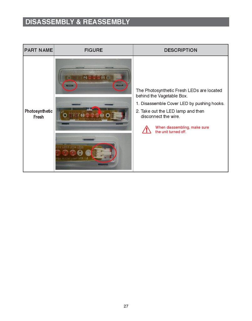
The Photosynthetic Fresh LEDs are located
behind the Vagetable Box.
1. Disassemble Cover LED by pushing hooks.
Photosynthetic
Fresh
2. Take out the LED lamp and then
disconnect the wire.
When diassembling, make sure
the unit turned off.
27
28.
DISASSEMBLY & REASSEMBLY3-5) Freezer Compartments
PART NAME
FIGURE
DESCRIPTION
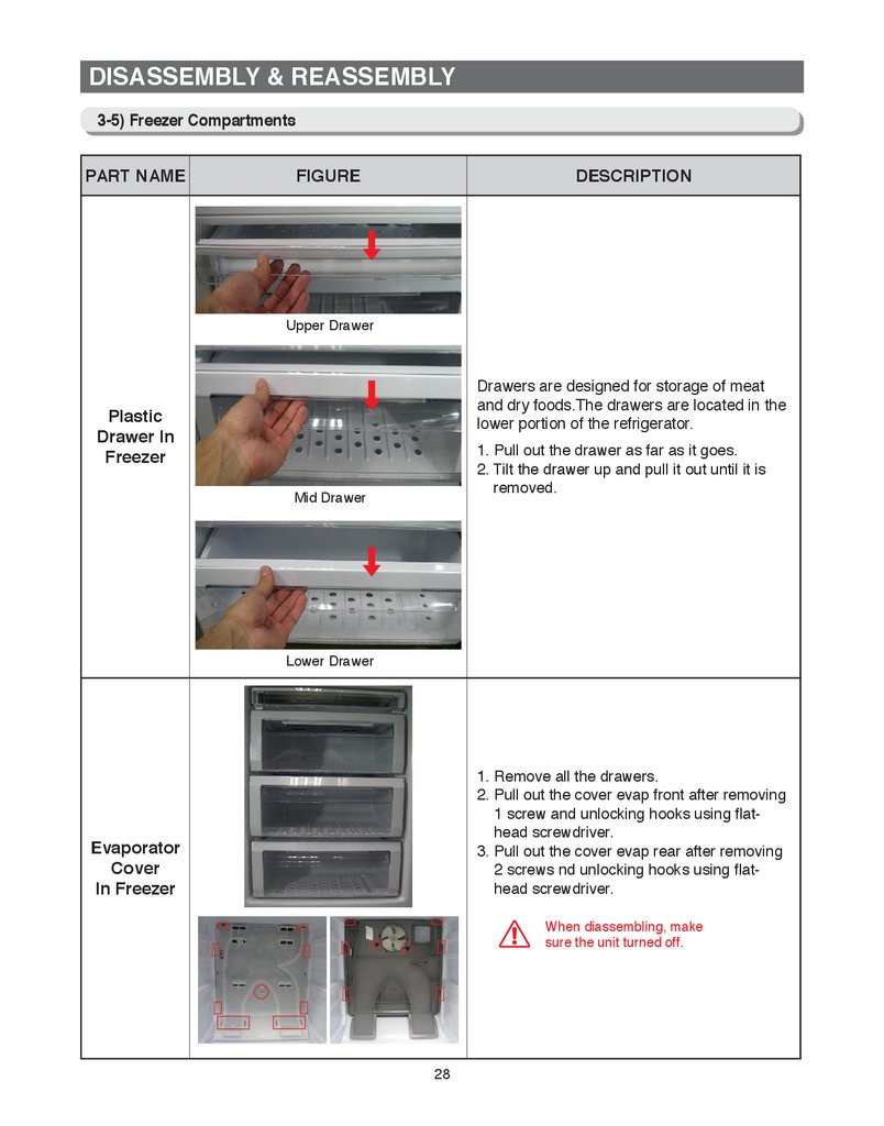
Upper Drawer
Drawers are designed for storage of meat
and dry foods.The drawers are located in the
lower portion of the refrigerator.
Plastic
Drawer In
Freezer
1. Pull out the drawer as far as it goes.
2. Tilt the drawer up and pull it out until it is
removed.
Mid Drawer
Lower Drawer
1. Remove all the drawers.
2. Pull out the cover evap front after removing
1 screw and unlocking hooks using flathead screwdriver.
3. Pull out the cover evap rear after removing
2 screws nd unlocking hooks using flathead screwdriver.
Evaporator
Cover
In Freezer
When diassembling, make
sure the unit turned off.
28
29.
DISASSEMBLY & REASSEMBLYPART NAME
FIGURE
DESCRIPTION
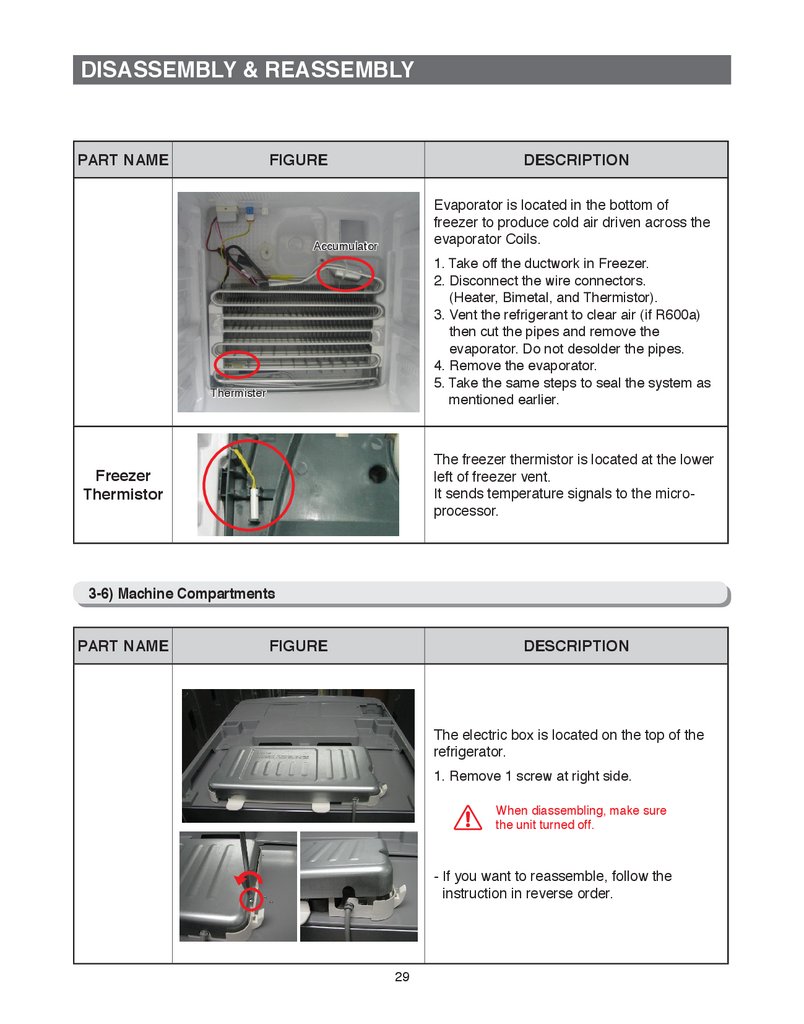
Evaporator is located in the bottom of
freezer to produce cold air driven across the
evaporator Coils.
Accumulator
1. Take off the ductwork in Freezer.
2. Disconnect the wire connectors.
(Heater, Bimetal, and Thermistor).
3. Vent the refrigerant to clear air (if R600a)
then cut the pipes and remove the
evaporator. Do not desolder the pipes.
4. Remove the evaporator.
5. Take the same steps to seal the system as
mentioned earlier.
Thermister
The freezer thermistor is located at the lower
left of freezer vent.
It sends temperature signals to the microprocessor.
Freezer
Thermistor
3-6) Machine Compartments
PART NAME
FIGURE
DESCRIPTION
The electric box is located on the top of the
refrigerator.
1. Remove 1 screw at right side.
When diassembling, make sure
the unit turned off.
- If you want to reassemble, follow the
instruction in reverse order.
29
30.
DISASSEMBLY & REASSEMBLY3-7) Reversing the Door swing
Read these instructions completely and carefully
Warning
• Before reversing the door, first of all, main power should be switched off you should
take out contents and accessories like door guard from the doors.
Be careful not to drop the doors during dissembling or assembling.
1. Handle parts carefully to avoid scratching paint.
2. Set screws down by their related parts to avoid using them in the wrong places.
3. Provide a non-scratching work surface for the doors. (ex:blanket)
4. During door reversing, refrigerator should not be stained with oil.
Not provided
Phillips Head
Driver (+)
PART NAME
Flat Head
Driver (-)
Additional part
10mm Socket
Wrench (for bolts)
11mm Wrench
(for hinge shaft)
FIGURE
3/16” Allen Wrench
(for middle hinge)
Top Left Hinge
Cover (Underneath
the Top Cover)
DESCRIPTION
1. With the door closed, remove 4 screws on
the top of the refrigerator.
2. Disconnect the wire underneath the Cap
Cabi, then take off the Cap Cabi.
Make sure the unit is unplugged
before reversing door.
DISASSEMBLY
OF THE
FRIDGE DOOR
3. Disconnect the wire.
4. Remove 3 bolts on the top of the
refrigerator.
Make sure the Fridge door is
closed firmily.
30
31.
DISASSEMBLY & REASSEMBLYPART NAME
FIGURE
DESCRIPTION
5. Remove the Fridge door from the Hinge
Mid by carefully lifting the door.
DISASSEMBLY
OF THE
FRIDGE DOOR
Fridge door is heavy, be careful
not to injure yourself when
removing the door.
HINGE MID
6. Disassemble the Freezer door by removing
2 bolts, a screw and the Hinge Mid.
Be careful not to drop and scratch
the Freezer Door.
DISASSEMBLY
OF THE
FREEZER
DOOR
COVER LEG
7. Detach the Front Leg Cover after removing
2 screws.
8. Unscrew 2 bolts tightening the Hinge Low
and also unscrew a bolt on the left side by
the front leg where removed the Hinge Low
will be attached.
HINGE LOW
Before removing the Assy Hinge Low,
slightly turn the front legs clockwise for
easier disassembling and reassembling.
ASSEMBLY OF
THE FREEZER
DOOR
AUTO GUIDE
9. Remove the screw on the Auto guide and
remove the Hinge shaft with 11mm wrench.
Attach the Hinge shaft on the left and put
the reversed Auto Guide back.
SHAFT
31
32.
DISASSEMBLY & REASSEMBLYPART NAME
FIGURE
DESCRIPTION
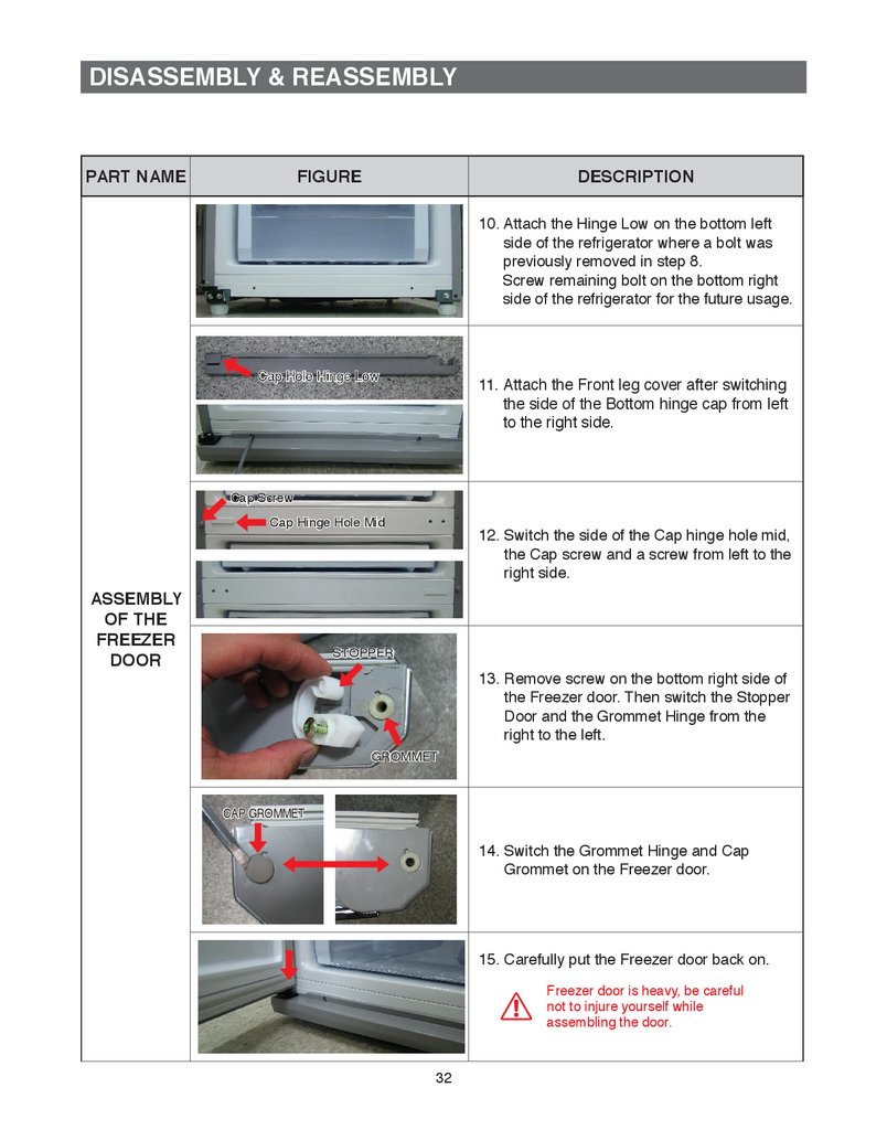
10. Attach the Hinge Low on the bottom left
side of the refrigerator where a bolt was
previously removed in step 8.
Screw remaining bolt on the bottom right
side of the refrigerator for the future usage.
11. A
ttach the Front leg cover after switching
the side of the Bottom hinge cap from left
to the right side.
Cap Screw
Cap Hinge Hole Mid
ASSEMBLY
OF THE
FREEZER
DOOR
12. Switch the side of the Cap hinge hole mid,
the Cap screw and a screw from left to the
right side.
STOPPER
GROMMET
13. Remove screw on the bottom right side of
the Freezer door. Then switch the Stopper
Door and the Grommet Hinge from the
right to the left.
CAP GROMMET
14. Switch the Grommet Hinge and Cap
Grommet on the Freezer door.
15. Carefully put the Freezer door back on.
Freezer door is heavy, be careful
not to injure yourself while
assembling the door.
32
33.
DISASSEMBLY & REASSEMBLYPART NAME
FIGURE
DESCRIPTION
16. Assemble the Hinge Mid with 2 bolts on
the left side.
HINGE MID
ASSEMBLY
OF THE
FREEZER
DOOR
A screw will be remained after
reversing door.
And it does not affect performance
of the refrigerator.
STOPPER
GROMMET
17. Remove screw on the bottom right side of
the Fridge door. Then switch the Stopper
Door and the Grommet Hinge from the
right to the left.
COVER WIRE DOOR
18. Remove the Cover Wire Door on the top
of the Fridge door with flat head driver.
ASSEMBLY
OF THE
FRIDGE
DOOR
ASSY HINGE UPP
19. Take out the Assy Hinge UPP from the
Fridge door.
20. Detach the Cover Wire Hinge R from the
Assy Hinge Upp and disassemble the
Wires.
21. Use 11mm wrench to separate the Hinge
Shaft and then flip the hinge and reattach
the Hinge Shaft.
HINGE SHAFT
33
34.
DISASSEMBLY & REASSEMBLYPART NAME
FIGURE
CAP SPACE
DESCRIPTION
GROMMET
22. Switch the Cap Space Door and the
Grommet Hinge on the Fridge door.
23. After switching wires from right side to the left
reassemble the Assy Hinge Upp by reversing
step 20. and put into the Fridge door. Make
sure to use the Cover Wire Hinge L which can
be found underneath the Cap Cabi. (Make
sure that red tape on the wire is positioned on
the end of the Cover Wire Hinge L as shown.)
ASSEMBLY
OF THE
FREEZER
DOOR
24. Carefully put the Fridge door back on.
25. Tighten 3 bolts to assemble the Assy
Hinge Upp.
26. Connect Wire.
34
35.
DISASSEMBLY & REASSEMBLYPART NAME
FIGURE
DESCRIPTION
27. Assemble the Cover Wire Door on the top
of the Fridge door.
CAP HOLE HINGE
28. Change the position of the Cap Hole
Hinge Upp. Connect wire under the Top
Table.
ASSEMBLY
OF THE
FRIDGE
DOOR
29. Put the Top Table back to its original
position with 4 screws.
30. Detach the Fridge and the Freezer gaskets
then attach them after rotating 180˚.
GASKET
After reversing the door, make
sure Fridge and Freezer gaskets
are properly arranged.
35
36.
DISASSEMBLY & REASSEMBLYPART NAME
FIGURE
DESCRIPTION
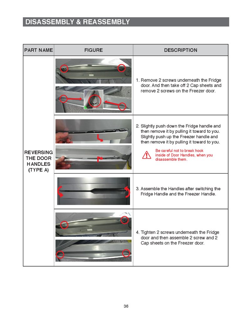
1. Remove 2 screws underneath the Fridge
door. And then take off 2 Cap sheets and
remove 2 screws on the Freezer door.
2. Slightly push down the Fridge handle and
then remove it by pulling it toward to you.
Slightly push up the Freezer handle and
then remove it by pulling it toward to you.
Be careful not to break hook
inside of Door Handles, when you
disassemble them.
REVERSING
THE DOOR
HANDLES
(TYPE A)
3. Assemble the Handles after switching the
Fridge Handle and the Freezer Handle.
4. Tighten 2 screws underneath the Fridge
door and then assemble 2 screw and 2
Cap sheets on the Freezer door.
36
37.
DISASSEMBLY & REASSEMBLYPART NAME
FIGURE
DESCRIPTION
1. Remove 2 screws underneath the Fridge
door and then pull the Cover Handle
forward to you.
Be careful not to break hooks
inside of Cover Handle, when you
disassemble it.
COVER HANDLE
HANDLE EASY
2. Disassemble the Handle Easy, after
removing 3 screws and the Grommet
Handles both side of the Fridge door.
GROMMET
REVERSING
THE DOOR
HANDLES
(TYPE B)
3. Change position of the Slider Handle and
the Spring from left to right side.
SLIDER HANDLE
SPRING
4. Assemble the Handle Easy with Grommet
Handle.
5. Assemble the Cover Handle with 2 screws.
37
38.
DISASSEMBLY & REASSEMBLY3-8) RELAY PROTECTOR O/L
PART NAME
FIGURE
DESCRIPTION
Disengage the housing connector.
(Refer to the picture)
Insert the flat-blade screwdriver into the
slot, and remove the Relay Cover along
the arrow.
Remove the Relay Protector O/L along the
arrow.
RELAY
PROTECTOR
O/L
Disassemble the Relay by pulling the
connector as shown.
Assemble in reverse order and be careful
not to change by checking initial position
assembled in relay.
Be careful not to assemble terminal
without white housing into the side tab
of relay.
(Models with 2pcs housing are
unrelated)
38
39.
4. TROUBLESHOOTING4-1) CHECK-LIST BEFORE TROUBLE-SHOOTING (T, H, E, W)··································· 41
4-1-1) TEST FUNCTION (FORCED OPERATION / FORCED DEFROST) ··············41
4-1-2) SELF-DIAGNOSIS FUNCTION ·····································································43
4-1-3) LOAD STATUS DISPLAY FUNCTION ···························································45
4-1-4) RESTORATION OF PREVIOUS SETTINGS UPON INSTANT POWER OUTAGE ··········47
4-1-5) DEMO MODE FUNCTION FOR STORE DISPLAY ·······································47
4-1-6) OPTION SETTING FUNCTION ·····································································48
4-1-7) OPTION TABLE ·····························································································49
4-1) CHECK-LIST BEFORE TROUBLE-SHOOTING (TT, TE, TW)································· 51
4-1-1) TEST FUNCTION (FORCED OPERATION / FORCED DEFROST) ··············51
4-1-2) SELF-DIAGNOSIS FUNCTION ·····································································53
4-1-3) LOAD STATUS DISPLAY FUNCTION ···························································56
4-1-4) RESTORATION OF PREVIOUS SETTINGS UPON INSTANT POWER OUTAGE ··········58
4-1-5) DEMO MODE FUNCTION FOR STORE DISPLAY ·······································58
4-1-6) OPTION SETTING FUNCTION ·····································································59
4-1-7) OPTION TABLE ·····························································································61
SERVICE FUNCTIONS (Q)······························································································ 64
4-1) CHECK POINTS PRIOR TO FAILURE DIAGNOSTICS··········································· 64
4-1-1) FORCED OPERATIONS ················································································64
4-1-2) COMMUNICATION ERROR DISPLAYS ························································65
4-1-3) SELF-DIAGNOSTICS ····················································································66
4-1-4) LOAD OPERATION CHECK ··········································································68
4-1-5) SHOWROOM MODE ·····················································································69
4-1-6) SET POINT SHIFT ·························································································70
4-1-7) ERROR HISTORY FUNCTION ······································································71
39
40.
TROUBLESHOOTING4-1-8) CHECK LCD PIXEL FUNCTION (J) ·······························································72
4-1-9) TOUCH POINT CALIBRATION ······································································74
4-1-10) USER DATA BACKUP/RESTORATION FUNCTION ···································75
4-1-11) OS UPGRADE FUNCTION ··········································································77
4-1) CHECK-LIST BEFORE TROUBLE-SHOOTING (VJ, VE, VW)································ 81
4-1-1) TEST FUNCTION (FORCED OPERATION / FORCED DEFROST) ··············81
4-1-2) SELF-DIAGNOSIS FUNCTION ·····································································83
4-1-3) LOAD STATUS DISPLAY FUNCTION ···························································86
4-1-4) RESTORATION OF PREVIOUS SETTINGS UPON INSTANT POWER OUTAGE ··········88
4-1-5) DEMO MODE FUNCTION FOR STORE DISPLAY ·······································88
4-1-6) OPTION SETTING FUNCTION ·····································································89
4-1-7) OPTION TABLE ·····························································································91
40
41.
TROUBLESHOOTING (S)4-1. Check-List before Trouble-Shooting
4-1-1) Test Function (Forced Operation / Forced Defrost)
● When the Cold and the Coldest buttons on the display panel are held down for more than 4
seconds, the entire display panel will blink in an interval of 0.5 second for about 3 seconds.
While the display panel blinks for 3 seconds, take your fingers off the Cold and the Coldest
buttons, and press the Coldest button to go into the Test mode.
At the Test mode, all the display buttons will work as the Test button.
● Each time the Test button is pressed, it will change in the following order.
F
orced Operation → Forced F-Defrost → Cancellation (Normal Operation) It is recommended
that the unit be disconnected and reconnected from the electricity supply to terminate the
operation of the Test function.
1) How to Enter Test Mode
①
②
① When pressing the Cold and the Coldest buttons for 4 seconds simultaneously, the entire
LEDs on the Display Panel will flash on and Off in an interval of 0.5 second for 3 seconds.
② While it is blinking, remove fingers from the two buttons and press the Coldest button to
enter the Test Mode.
③ Remove finger and press any button to enter the Test Mode.
41
42.
TROUBLESHOOTING (S)2) Test Mode Description
1. Forced Operation Function
1-1) When any button is pressed at the Test Mode, the Temp. LED will set to the Coldest indicating
that it is in the Forced Operation.
1-2) When the Forced Operation is selected, the compressor starts without a 7-minute delay in
any operation mode. At this time, when it is in a Defrost mode, it stops defrosting and the
Forced Operation begins. (If the Forced Operation begins as soon as the compressor stops,
it may cause the overload. So, take care when entering into the Forced Operation.)
1-3) When the Forced Operation is selected, the compressor and the F-Fan operate for 24 hours
without stopping and the Fridge compartment will operate according to the set temperature.
1-4) When the unit is shifted to the Forced Operation, the Temp. LED will set to "Coldest"
(Freezer : -25ºC, Fridge : 1ºC).
1-5) To cancel the Forced Operation in the middle of the Test function, turn off the power and
turn it on again, or select the Test Cancellation mode.
2. Forced Defrost Function
2-1) When the Test button is pressed once more at the Forced Operation (Coldest), the Temp.
LED will set to "Colder (medium)". And, the Forced Operation will be cancelled right away
and the Forced F-Defrost will start.
2-2) For this function, the lower 3 LED sections (Cold, Cold/Mid, Mid) will light up.
3. Test Cancellation Mode
3-1) W
hen turning the display panel into the Test mode and pressing the TEST button once more
during the Forced F-Defrost, the Forced F-Defrost will be cancelled and it will go back to the
normal operation. Also, disconnect and reconnect the unit from the electricity supply to exit
the test mode.
42
43.
TROUBLESHOOTING (S)4-1-2) Self-Diagnosis Function
1) Self-Diagnosis Function upon Initial Power-On
1-1) When the unit is plugged into the power, MICOM diagnoses the status of the temperature
sensors in a few minutes.
1-2) If defective sensor is found after Self-Diagnosis, relevant Display LEDs will blink at an
interval of 0.5 sec. and there will be no beeping sound. (Refer to the Self-Diagnosis Check
List)
1-3) When there is a defective sensor found and its relevant LED blinks, it will only recognize the
Self-Diagnosis button combination and it doesn't show the normal display.
But, the temperature will be controlled with the Emergency Operation.
1-4) To cancel the error code, fix the failure of the defective sensor or cancel the Initial SelfDiagnosis Function by pressing the Cold and the Coldest buttons for 13 seconds.
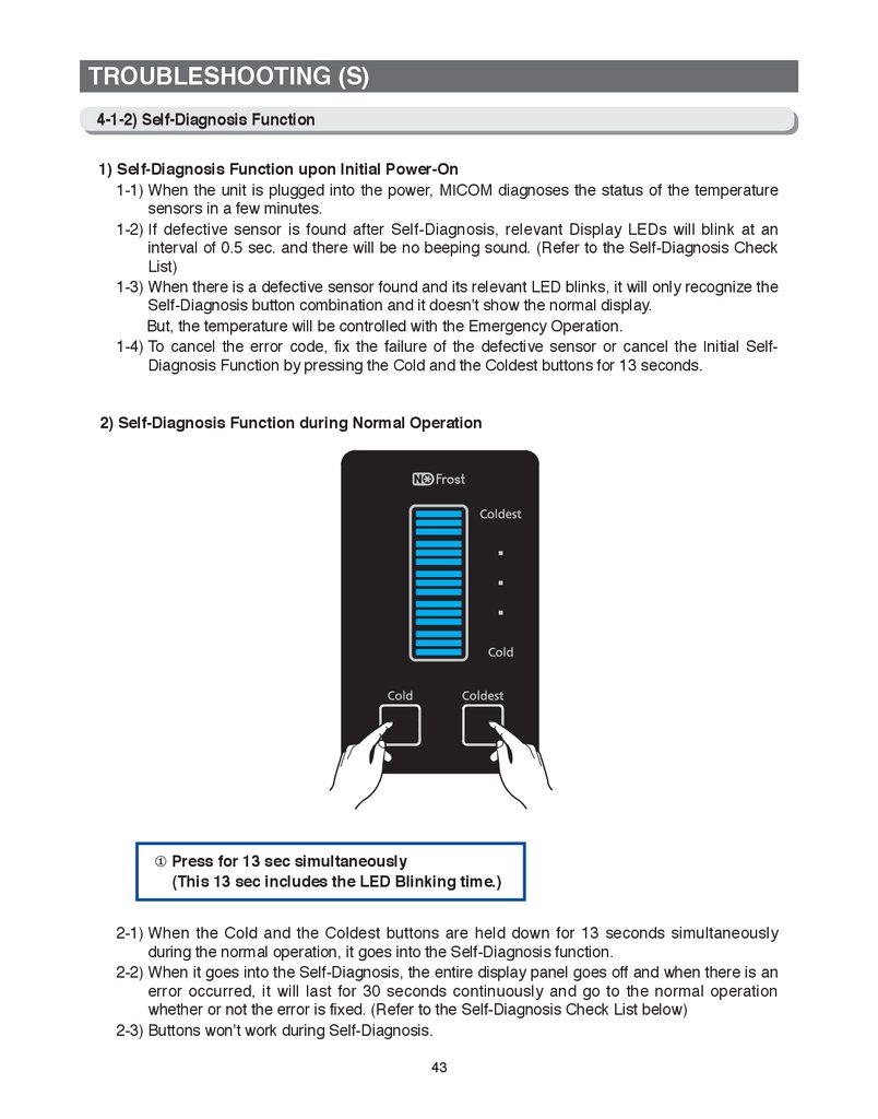
2) Self-Diagnosis Function during Normal Operation
① Press for 13 sec simultaneously
(This 13 sec includes the LED Blinking time.)
2-1) When the Cold and the Coldest buttons are held down for 13 seconds simultaneously
during the normal operation, it goes into the Self-Diagnosis function.
2-2) When it goes into the Self-Diagnosis, the entire display panel goes off and when there is an
error occurred, it will last for 30 seconds continuously and go to the normal operation
whether or not the error is fixed. (Refer to the Self-Diagnosis Check List below)
2-3) Buttons won't work during Self-Diagnosis.
43
44.
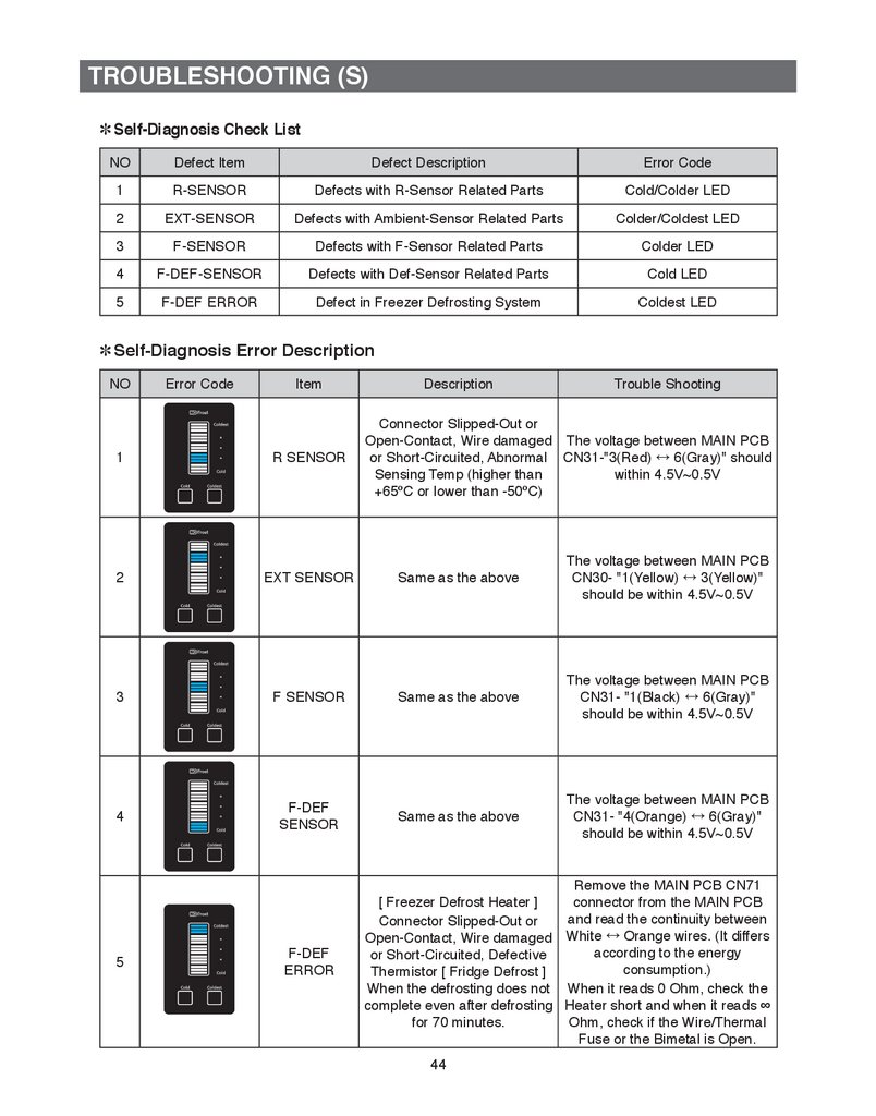
TROUBLESHOOTING (S)✽ Self-Diagnosis Check List
NO
Defect Item
Defect Description
Error Code
1
R-SENSOR
Defects with R-Sensor Related Parts
Cold/Colder LED
2
EXT-SENSOR
Defects with Ambient-Sensor Related Parts
Colder/Coldest LED
3
F-SENSOR
Defects with F-Sensor Related Parts
Colder LED
4
F-DEF-SENSOR
Defects with Def-Sensor Related Parts
Cold LED
5
F-DEF ERROR
Defect in Freezer Defrosting System
Coldest LED
✽ Self-Diagnosis Error Description
NO
Error Code
Item
Description
Trouble Shooting
Connector Slipped-Out or
Open-Contact, Wire damaged The voltage between MAIN PCB
or Short-Circuited, Abnormal CN31-"3(Red) ↔ 6(Gray)" should
Sensing Temp (higher than
within 4.5V~0.5V
+65ºC or lower than -50ºC)
1
R SENSOR
2
EXT SENSOR
Same as the above
The voltage between MAIN PCB
CN30- "1(Yellow) ↔ 3(Yellow)"
should be within 4.5V~0.5V
3
F SENSOR
Same as the above
The voltage between MAIN PCB
CN31- "1(Black) ↔ 6(Gray)"
should be within 4.5V~0.5V
4
F-DEF
SENSOR
Same as the above
The voltage between MAIN PCB
CN31- "4(Orange) ↔ 6(Gray)"
should be within 4.5V~0.5V
5
F-DEF
ERROR
Remove the MAIN PCB CN71
[ Freezer Defrost Heater ]
connector from the MAIN PCB
and read the continuity between
Connector Slipped-Out or
Open-Contact, Wire damaged White ↔ Orange wires. (It differs
according to the energy
or Short-Circuited, Defective
consumption.)
Thermistor [ Fridge Defrost ]
When the defrosting does not When it reads 0 Ohm, check the
complete even after defrosting Heater short and when it reads ∞
for 70 minutes.
Ohm, check if the Wire/Thermal
Fuse or the Bimetal is Open.
44
45.
TROUBLESHOOTING (S)4-1-3) Load Status Display Function
1) At the normal operation, press the Cold + Coldest buttons for 7 seconds.
Then, the "Colder (Cold), Colder (Mid), Colder (Coldest)" LED section will blink in an interval of
0.5 second for 3 seconds.
2) At this time, release the Cold + Coldest buttons and press the Cold button.
Then, it shifts to the Load Display mode.
3) The Load Display function shows what MICOM signals come out from MAIN PCB.
But, it just indicates that there are MICOM signals coming out. It does not necessarily mean that
the related parts (Loads) are operating. In other word, even though it shows a certain load
working, the related part may not operate due to such as a defective PCB relay or the defective
part itself (it needs checking).
4) The Load Display function lasts for 30 seconds and then it goes back to the normal operation.
① When pressing the buttons for 7 seconds simultaneously, the "Colder (Cold), Colder
(Mid), Colder (Coldest)" LED section blinks in an interval of 0.5 second for 3 seconds.
② At this time, release the buttons and press the Cold button.
Then, it will shift to the Load Test Mode.
45
46.
TROUBLESHOOTING (S)✽ Load Mode Check List
NO
Defect Item
①
Overload
②
Low Temperature
③
Normal Operation
⑤
COMP
⑧
Freezer Defrost
Heater
⑩
Fridge Damper Open
Defect Description
Error Code
LED On when the ambient
temperature is over 34ºC
Cold/Colder LED
LED On when the ambient
temperature is lower than 21ºC
Cold LED
Cold/Colder & Cold LEDs are all Off
When the ambient temperature
is between 22ºC~33ºC
Coldest LED
LED On when the COMP
operates
Colder/Coldest LED
LED On when the Freezer
Defrost
Heater is on
When the Fridge Damper is
Open
Colder LED
46
47.
TROUBLESHOOTING (S)4-1-4) Restoration of Previous Settings upon Instant Power Outage
1) If the Display Panel is initialized by the instant power outage, it will cause customer inquiries. To
prevent this, when the power is restored, the previous settings will be restored or reset based on
the inside temperature of the unit.
2) Upon the initial power on, it checks its Freezer temperature. When it is lower than +5ºC, it is to
be considered as an instant power failure and it brings back all its previous operation functions
(Temp. Control LED, Operation Function, etc) related to the panel display.
3) When it is higher than +5ºC, it is to be considered as a long-period power failure and it will initialize
the panel display. [set to "Colder (Mid)"] (Freezer: -19ºC, Fridge: 3ºC : "Colder (Mid) Setting Values)
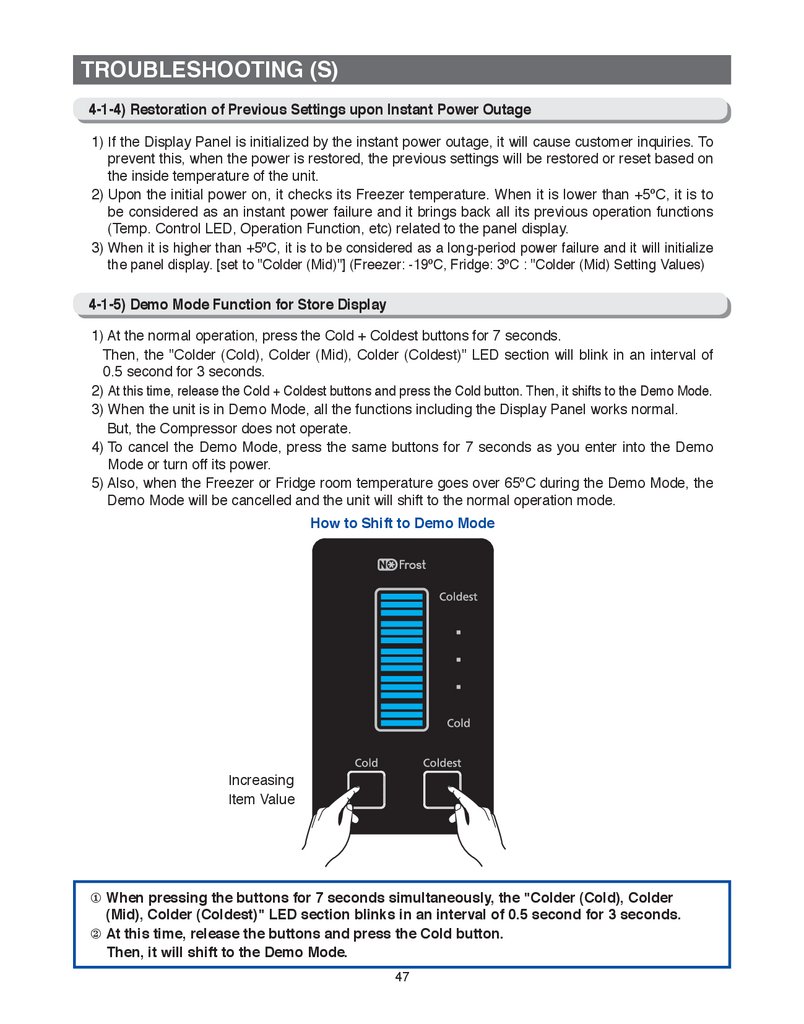
4-1-5) Demo Mode Function for Store Display
1) At the normal operation, press the Cold + Coldest buttons for 7 seconds.
Then, the "Colder (Cold), Colder (Mid), Colder (Coldest)" LED section will blink in an interval of
0.5 second for 3 seconds.
2) At this time, release the Cold + Coldest buttons and press the Cold button. Then, it shifts to the Demo Mode.
3) When the unit is in Demo Mode, all the functions including the Display Panel works normal.
But, the Compressor does not operate.
4) To cancel the Demo Mode, press the same buttons for 7 seconds as you enter into the Demo
Mode or turn off its power.
5) Also, when the Freezer or Fridge room temperature goes over 65ºC during the Demo Mode, the
Demo Mode will be cancelled and the unit will shift to the normal operation mode.
How to Shift to Demo Mode
Increasing
Item Value
① When pressing the buttons for 7 seconds simultaneously, the "Colder (Cold), Colder
(Mid), Colder (Coldest)" LED section blinks in an interval of 0.5 second for 3 seconds.
② At this time, release the buttons and press the Cold button.
Then, it will shift to the Demo Mode.
47
48.
TROUBLESHOOTING (S)4-1-6) Option Setting Function
● Press the the Cold + Coldest buttons on the Display Panel for 4 seconds simultaneously. Then,
the entire Display Panel will blink in an interval of 0.5 second for 3 seconds. While the entire
Display Panel is blinking, it shifts to the Option Mode when the Cold button is pressed.
● When there is no button press for 20 seconds at the Option Setting Mode, it will go back to the normal
display mode. There are two modes in the Option Setting Mode. When the Coldest LED is on, it displays
the Item Number. And, when the Coldest LED is off, it displays the Item Value. At the Item Number Display
Mode, press the Coldest button to shift it to the Item Value Display Mode and keep pressing the Coldest
button until selecting a desired Item Value. At the Item Value Display Mode, press the Cold button to shift it
to the Item Number Display Mode and keep pressing the Cold button until selecting a desired Item Value.
How to Shift to Option Setting Mode
① When pressing the Cold + Coldest buttons for
4 seconds simultaneously, the entire Temp.
LEDs will blink in an interval of 0.5 second for
3 seconds.
② At this time, release the buttons and press the
Cold button.
Option Mode & Button Description
On : Item #
Off : Item Value
Item # or
Item Value
Increasing
Item Value
Setting Item #
Note Basically, when units being shipped out, all the data in the Option function are cleared.
That is, the Default settings are “0”. However, for the purpose of quality improvement during mass production,
the Default values may change. Therefore, be sure to check quality information, such as SVC bulletins.
48
49.
TROUBLESHOOTING (S)4-1-7) Option Table
1) Freezer Temperature Shifting Table
Ex) Freezer Temperature : -1.0ºC Shift
Option Mode & Button Description
On : Item #
Off : Item Value
Item # or
Item Value
Increasing
Item Value
Setting Item #
0 ºC
-0.5 ºC
-1.0 ºC
-1.5 ºC
0.5 ºC
49
1.0 ºC
1.5 ºC
2.0 ºC
50.
TROUBLESHOOTING (S)2) Fridge Temperature Shifting Table
Ex) Fridge Temperature : -1.0ºC Shift
Option Mode & Button Description
On : Item #
Off : Item Value
Item # or
Item Value
Increasing
Item Value
Setting Item #
0 ºC
-0.5 ºC
-1.0 ºC
-1.5 ºC
0.5 ºC
50
1.0 ºC
1.5 ºC
2.0 ºC
51.
TROUBLESHOOTING (TT, TE, TW)4-1. Check-List before Trouble-Shooting
4-1-1) Test Function (Forced Operation / Forced Defrost)
● When the Power Freeze and the Fridge buttons on the display panel are held down for more
than 8 seconds, the Panel Display will be off and it goes into the Test Mode. At the Test mode, all
the display buttons will work as the Test button.
● Each time the Test button is pressed, it will change in the following order.
F
orced Operation → Forced F-Defrost (Fd) → Cancellation (Normal Operation) It is
recommended that the unit unit be disconnected and reconnected from the electricity supply to
in to terminate the operation of the Test function.
1) How to Enter Test Mode
① Press for 8 seconds simultaneously
② When pressing any one of the five buttons, it will go into the Test Mode.
51
52.
TROUBLESHOOTING (TT, TE, TW)2) Test Mode Description
1. Forced Operation Function
1-1) Each time any button is pressed during the Test Mode, the display lamp changes in the
order of “FF 1”, "FF 2" and "FF 3" indicating that it is in the Forced Operation.
At this time, it starts alarming with “Beep” sounds.
1-2) When the Forced Operation is selected, the compressor starts without a 7-minute delay in
any operation mode. At this time, when it is in a Defrost mode, it stops defrosting and the
Forced Operation begins. (If the Forced Operation begins as soon as the compressor stops,
it may cause the overload. So, take care when entering into the Forced Operation.)
1-3) When the Forced Operation is selected, the compressor and the F-Fan operate for 24 hours
without stopping and the Fridge compartment will operate according to the set temperature.
1-4) When the unit is shifted to the Forced Operation, the Freezer and the Fridge temperatures
will be set to -25ºC and 1ºC.
1-5) W
hen the Forced Operation is selected, the Power Freeze function won't work.
And, when the Power Freeze function is selected, the Power Freeze LED will go off in 10 seconds.
1-6) To cancel the Forced Operation in the middle of the Test function, turn off the power and
turn it on again, or select the Test Cancellation mode.
1-7) The alarm sound during the Forced Operation (0.25 sec On and 0.75 sec Off) keeps on until
the Forced Operation completes and there is no cancellation function.
2. Forced Defrost Function
2-1) When the Test button is pressed once more at the Forced Operation (FF), “Fd” lights up on
the Display Panel and the Forced Operation will be cancelled and the Freezer compartment
starts defrosting.
2-2) At this time, it sends out "Beeping" sound for 3 seconds. This alarm sound repeats (0.5 sec
On and 0.5 sec Off) which keeps on until the Forced F-Defrost finishes.
3. Test Cancellation Mode
3-1) W
hen turning the display panel into the Test mode and pressing the TEST button once more during
the Forced F-Defrost, the Forced F-Defrost will be cancelled and it will go back to the normal
operation. Also, when the unit is plugged out and in again, the Test mode is to be deactivated.
52
53.
TROUBLESHOOTING (TT, TE, TW)4-1-2) Self-Diagnosis Function
1) Self-Diagnosis Function upon Initial Power-On
1-1) When the unit is plugged into the power, MICOM diagnoses the status of the temperature
sensors in a few minutes.
1-2) If defective sensor is found after Self-Diagnosis, relevant Display LEDs will blink at an
interval of 0.5 sec. and there will be no beeping sound. (Refer to the Self-Diagnosis Check
List)
1-3) When there is a defective sensor found and its relevant LED blinks, it will only recognize the
Self-Diagnosis button combination and it doesn't do the normal display. But, the
temperature will be controlled with the Emergency Operation.
1-4) To cancel the error code, fix the failure of the defective sensor or cancel the Initial SelfDiagnosis Function by pressing the Power Freeze and the Vacation buttons for 8 seconds.
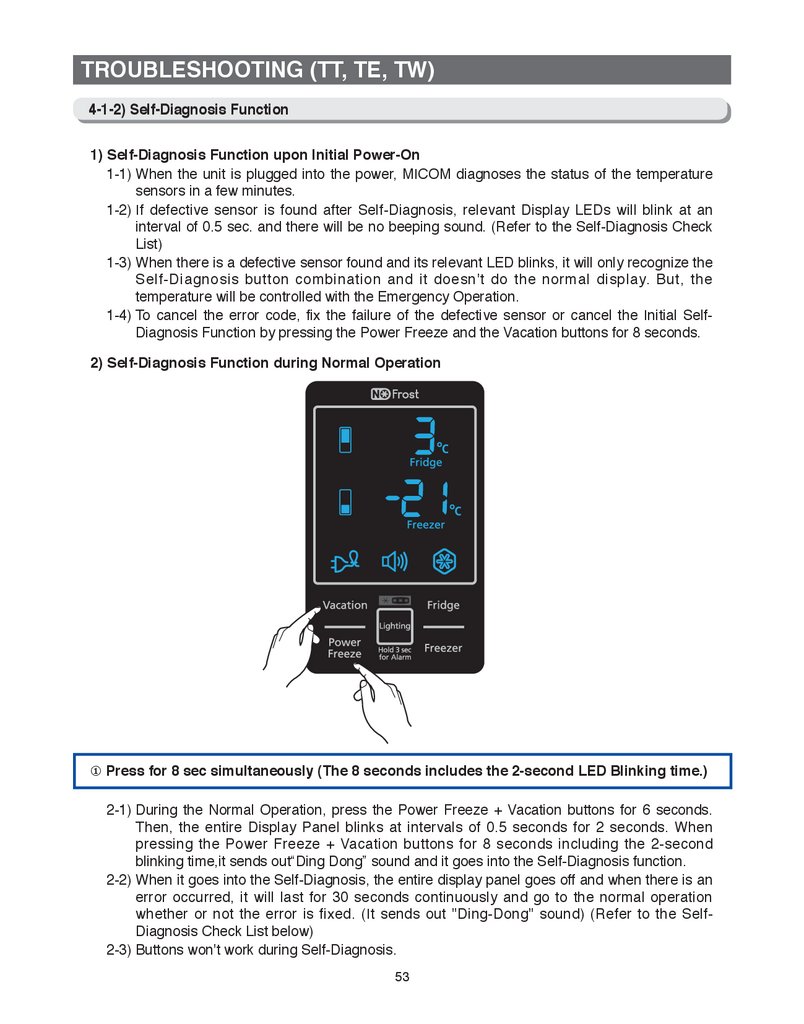
2) Self-Diagnosis Function during Normal Operation
① Press for 8 sec simultaneously (The 8 seconds includes the 2-second LED Blinking time.)
2-1) During the Normal Operation, press the Power Freeze + Vacation buttons for 6 seconds.
Then, the entire Display Panel blinks at intervals of 0.5 seconds for 2 seconds. When
pressing the Power Freeze + Vacation buttons for 8 seconds including the 2-second
blinking time,it sends out“Ding Dong” sound and it goes into the Self-Diagnosis function.
2-2) When it goes into the Self-Diagnosis, the entire display panel goes off and when there is an
error occurred, it will last for 30 seconds continuously and go to the normal operation
whether or not the error is fixed. (It sends out "Ding-Dong" sound) (Refer to the SelfDiagnosis Check List below)
2-3) Buttons won't work during Self-Diagnosis.
53
54.
TROUBLESHOOTING (TT, TE, TW)F-10
R/F-1
a
f
g
e
d
a
b
f
c
e
g
c
d
When there is an 8-segment LED
blinking, it indicates that there
is an error to its related parts.
Ex) R 2nd Digit (R-1) "b" :
R-Sensor Related Error
✽ Self-Diagnosis Check List
NO
Category
Defect Description
Error Code
1
R-SENSOR
Defects in Parts related to R-SENSOR
Fridge Digit (R-1) : "b"
2
CSZ-SENSOR
Defects in Parts related to CSZ-SENSOR
Fridge Digit (R-1) : "f"
3
EXT-SENSOR
Defects in Parts related to EXT-SENSOR
Fre 2nd Digit (F-1) : "a"
4
F-SENSOR
Defects in Parts related to F-SENSOR
Fre 2nd Digit (F-1) : "b"
5
F-DEF-SENSOR
Defects in Parts related to F-DEF-SENSOR
Fre 2nd Digit (F-1) : "c"
6
F-FAN Error
Defects in Parts related to F-FAN
Fre 2nd Digit (F-1) : "d"
7
F-DEFROST Error
Defects in Parts related to F-DEFROST
Fre 2nd Digit (F-1) : "g"
8
Damper Heater
Error
Damper Heater open / Wire Defects
Fre 1st Digit (F-10) : "b"
54
b
55.
TROUBLESHOOTING (TT, TE, TW)✽ Self-Diagnosis Error Description
NO
Item
Description
Trouble Shooting
1
R SENSOR
Connector Slipped-Out or
Open-Contact, Wire damage
or Short-Circuited, Abnormal
Sensing Temp (higher than
+65ºC or lower than -50ºC)
The voltage between MAIN PCB
CN31-"3(Red) ↔ 6(Gray)" should
within 4.5V~0.5V
2
CSZ SENSOR
Same as the R SENSOR
The voltage between MAIN PCB
CN31- "2(Brown) ↔ 6(Gray)"
should be within 4.5V~0.5V.
3
EXT SENSOR
Same as the R SENSOR
The voltage between MAIN PCB
CN30- "1(Yellow) ↔ 3(Yellow)"
should be within 4.5V~0.5V
4
F SENSOR
Same as the R SENSOR
The voltage between MAIN PCB
CN31- "1(Black) ↔ 6(Gray)"
should be within 4.5V~0.5V
5
DEF SENSOR
Same as the R SENSOR
The voltage between MAIN PCB
CN31- "4(Orange) ↔ 6(Gray)"
should be within 4.5V~0.5V
6
7
8
Error Code
When the related Fan Motor
operates, it occurs if the
contact of the Feed Back
F-FAN ERROR
Signal Wire is defective, the
Motor Wire is slipped out or the
Motor is defective.
[ Freezer Defrost Heater ]
Connector Slipped-Out or OpenContact, Wire damage or ShortCircuited, Defective Thermistor
F-DEF
ERROR
[ Fridge Defrost ]
When the defrosting does not
complete even after it does
defrosting for 70 minutes.
DAMPER
HEATER
ERROR
The voltage between MAIN PCB
CN72-"5(Gray) ↔ 4(Sky Blue)"
should be within 7V~12V
Remove the MAIN PCB CN71 connector
from the MAIN PCB and read the
continuity between White ↔ Orange
wires. (It differs according to the energy
consumption.) When it reads 0 Ohm,
check the Heater short and when it
reads ∞ Ohm, check if the Wire/Thermal
Fuse or the Bimetal is Open.
Remove the MAIN PCB CN75 connector
from the MAIN PCB and read the
It occurs when the Damper
Heater is detected as open due continuity between 1(Black) ↔ 2(Brown)
wires. (Around 140 ~ 160 Ohm)
to the slipped-out connector,
the open contact or the open When it reads 0 Ohm, check the Heater
wire of the Damper Heater. short and when it reads ∞ Ohm, check if
the wire is open or slipped out.
55
56.
TROUBLESHOOTING (TT, TE, TW)4-1-3) Load Status Display Function
1) At the normal operation, press the Power Freeze + Vacation buttons for 6 seconds.
Then, the entire Display Panel will blink in an interval of 0.5 second for 2 seconds.
2) At this time, release the Power Freeze + Vacation buttons and press the Fridge button (it sends
out "Ding Dong" sound.) Then, it shifts to the Load Display mode.
3) The Load Display function shows what MICOM signals come out from MAIN PCB.
But, it just indicates that there are MICOM signals coming out. It does not necessarily mean that
the related parts (Loads) are operating. In other word, even though it shows a certain load
working, the related part may not operate due to such as a defective PCB relay or the defective
part itself (it needs checking).
4) The Load Display function lasts for 30 seconds and then it goes back to the normal operation.
① Press the Power Freeze + Vacation
buttons for 6 seconds
simultaneously. Then, the Display
LEDs will blink for 2 seconds.
② At this time, release the buttons and
press the Fridge bu
e.
①
②
①
5) The following image shows load locations with the 7-segment LEDs.
F-10
R/F-1
a
f
g
e
d
56
a
b
f
c
e
g
b
c
d
57.
TROUBLESHOOTING (TT, TE, TW)✽ Load Mode Check List
NO
Defect Item
①
Overload
Defect Description
Error Code
Fridge "e"
LED On when the ambient
temperature is
over 34ºC
Fridge "f"
LED On when the ambient
temperature is
lower than 21ºC
②
Low Temperature
③
Normal Operation
④
Demo Mode
⑤
COMP
Freezer 2nd Digit "a"
LED On when Comp is running
⑥
F FAN HIGH
Freezer 2nd Digit "b"
LED On when the F-Fan runs
High
⑦
F FAN LOW
Freezer 2nd Digit "c"
LED On when the F-Fan runs
Low
⑧
F-DEF HEATER
Freezer 2nd Digit "d"
LED On when the Freezer
Defrost Heater is on
⑨
CSZ Room
Damper Open
Freezer 1st Digit "f"
CSZ Room Damper
Open(OPTION)
⑩
R Room
Damper Open
Freezer 1st Digit "g"
When the Fridge Damper is
Open
Fridge "e","f" LEDs are all off.
When the ambient temperature
is between 22ºC~33ºC
LED On when the unit is on
Demo Mode
Fridge "g"
57
58.
TROUBLESHOOTING (TT, TE, TW)4-1-4) Restoration of Previous Settings upon Instant Power Outage
1) If the Display Panel is initialized by the instant power outage, it will cause customer inquiries. To
prevent this, when the power is restored, the previous settings will be restored or reset based on
the inside temperature of the unit.
2) Upon the initial power on, it checks its Freezer temperature. When it is lower than +5ºC, it is to
be considered as an instant power failure and it brings back all its previous operation functions
(Power Freeze, Vacation, Fridge, Freezer, Alarm On, etc) related to the panel display.
3) When it is higher than +5ºC, it is to be considered as a long-period power failure and it will
initialize the panel display. (Freezer: -20ºC, Fridge: 3ºC)
4-1-5) Demo Mode Function for Store Display
1) At the normal operation, press the Power Freeze + Freezer buttons for 8 seconds.
Then, it shifts to the Demo Mode.
2) When the unit is in Demo Mode, all the functions including the Display Panel works normal.
But, the Compressor does not operate.
3) To cancel the Demo Mode, press the same buttons for 8 seconds as you enter into the Demo
Mode or turn off its power.
4) Also, when the Freezer or Fridge room temperature goes over 65ºC during the Demo Mode, the
Demo Mode will be cancelled and the unit will shift to the normal operation mode.
5) The initial real temperature display function will end.
How to Shift to Demo Mode
Press the Power Freeze + Freezer buttons for 8 seconds simultaneously
58
59.
TROUBLESHOOTING (TT, TE, TW)4-1-6) Option Setting Function
● W
hen the Vacation + Freezer buttons are pressed for 12 seconds during the normal operation
mode, the Display will shift to the Option Setting Mode.
● When there is no button press for 20 seconds at the Option Setting Mode, it will go back to the
normal display mode.
How to Shift to Option Setting Mode
① When pressing the Freezer + Vacation
buttons for 12 seconds simultaneously,
it will shift to the Option Service Mode.
Option Mode & Button Description
Item# 2nd Digit
Item# 1st Digit
00 ~ 09 : All Off
10 ~ 19 : Off – Off - On
20 ~ 29 : Off – On - On
30 ~ 39 : On – On - On
Item Set-Value
Item# Down
Item# Up
Item Set-Value
Down
Item Set-Value
Up
59
60.
TROUBLESHOOTING (TT, TE, TW)● When the Display Panel converts to the Option Setting mode, the entire Display except the
Fridge as shown below Temp LED goes off.
Freezer Temp Setting
Fridge Temp Setting
1) For example, if you want to shift the standard temp of the Freezer compartment by -2ºC, follow the
steps below.
This function is to change the default temperature and when the default temperature of the Freezer
compartment is -20ºC and the default setting is lowered by -2ºC with the Option function, the default
temperature will be controlled at -22ºC.
That is, when changing temperature options, the Freezer compartment will operate at -22ºC internally
even if it shows -20ºC on the display panel.
Therefore, the temperature will be controlled by -2ºC lower than the set temperature on the display panel.
Note Basically, when units being shipped out, all the data in the Option function are cleared.
That is, the Default settings are “0”. However, for the purpose of quality improvement during
mass production, the Default values may change. Therefore, be sure to check quality
information, such as SVC bulletins.
2) After changing into the Option mode, “0"s on both of the Fridge and Freezer compartments lights
up on the display panel. (when units being shipped out, the unit will be shipped out with "0"s set
on both of the Fridge and Freezer compartments. However, for the purpose of quality
improvement during mass production, the Default values may change.)
- When only “0” lights up on the Fridge compartment, the Freezer temperature option can be set
and the current set Freezer temperature will show on the display panel.
3) I f the Freezer temp code is set to "4" as the following table after setting the Fridge section to "0", the
Freezer base temperature is to be lowered by -2ºC (Refer to the Freezer temperature setting image.)
: In 15 seconds after completing the adjustment, MICOM is to store the setting value in EEPROM
and it goes back to the normal display mode, deactivating the Option Setting mode.
5) The Fridge temperature can be adjusted with the same method.
6) Make sure not to change the factory-set default values except in extreme cases.
Also, the Option Setting is to be completed when it goes back to the normal display mode.
So, do not turn off the unit before it goes back to the normal display mode.
60
61.
TROUBLESHOOTING (TT, TE, TW)4-1-7) Option Table
Note T
here are other option setting functions not for repair purposes.
S
o, they are not handled in this manual.
(Except those described in this manual, do not change other values.)
1) Freezer Temp Shift Table
Setting Item
Freezer Temp Shift
MODEL
T, E, W
Option Item
Setting Value
Location : Fridge Temp LED
0
Fridge Temp
Option
Value
0
0
1
-0.5ºC
2
-1.0ºC
3
-1.5ºC
4
-2.0ºC
5
-2.5ºC
6
-3.0ºC
7
-3.5ºC
8
+0.5ºC
9
+1.0ºC
10
+1.5ºC
11
+2.0ºC
12
+2.5ºC
13
+3.0ºC
14
+3.5ºC
15
+4.0ºC
Ex) When shifting the Freezer
default temp by -2.0ºC
61
62.
TROUBLESHOOTING (TT, TE, TW)1) Fridge Temp Shift Table
Setting Item
Fridge Temp Shift
MODEL
T, E, W
Option Item
Setting Value
Location : Freezer Temp LED
1
Freezer Temp
Option
Value
0
0
1
-0.5ºC
2
-1.0ºC
3
-1.5ºC
4
-2.0ºC
5
-2.5ºC
6
-3.0ºC
7
-3.5ºC
8
+0.5ºC
9
+1.0ºC
10
+1.5ºC
11
+2.0ºC
12
+2.5ºC
13
+3.0ºC
14
+3.5ºC
15
+4.0ºC
Ex) When shifting the Fridge
default temp by +2.0ºC
62
63.
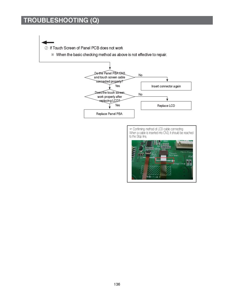
TROUBLESHOOTING (Q)Service Functions
Functions
How to operate
Keys
Time
Use this functions...
Forced Operation
“Lighting” + “Alarm”
To set the forced operation and forced defrost.
Showroom Mode
"Slide Show" + "Lighting"
To set Display Mode at the shop.
To calibrate the stylus pen touch point of LCD
Touch Screen
Touch screen Calibrations “Lighting” + “Home”
Self-Diagnostics
To check the failure modes.
Load Operation Check
Set Point Shift Mode
Error History
8 sec
To check the present operating load of
refrigerator.
To change the setting options about the regrigerator operating
status. Need careful decision for the option change.
“Slide Show” + “Home”
To check the latest 5 errors.
Check LCD Pixel
To check the LCD Pixel failures.
User Data Back up/
Restoration
To back up & restoration the user’s data when
update software and/or replace PBA panel.
63
64.
TROUBLESHOOTING (Q)4-1. Check Points prior to Failure Diagnostics
4-1-1) Forced Operations
1) Forced Operation settings
Sequence
Note
①T
o display the test mode, press and hold the
“Lighting” button and “Alarm” button for 8sec
simulataneously.
② Choose the “NEXT>>” button.
When “NEXT” button is selected, the next
displayed mode is automatically run.
※ Operationg Sequence of the NEXT button
Stop ForceTest -> ForceRun1 -> ForceRun2 ->
ForceRun3 -> Force FZ Defrost ->
Stop ForceTest
2) Force Test (Pull-down)
2-1) At the Force Test mode, press "NEXT>>" button once then the buzzer will beep
until this mode is cancelled.
2-2) At this Force Test (pull-down) mode, the compressor will start immediately and if
the system is in the defrost cycle, defrost cycle will be cancelled right away.
NOTE) I f this Force Test (pull-down) mode begins right after the compressor was off,
the compressor may not start running due to an overload condition.
2-3) At this mode, the compressor and freezer fan will operate continuously for 24
hours and the refrigerator fan will be on and off according to the set temperature.
2-4) When Force Test (pull-down) mode is selected, FZ compartment temperature will
be set as -25℃ and FF compartment temperature will be set as 1℃.
2-5) Power Freeze is not available during Force Test (pull-down) mode.
2-6) In order to cancel this mode at any time, choose the Stop Force Test on the Force
Test mode or power off the system.
3) Force FZ Defrost
3-1) At the Force Run mode, press "NEXT>>" button again on the Force Test mode to
begin the defrost cycle for the refrigerator.
3-2) The beep sound continues until Force FZ Defrost mode is ceased.
64
65.
TROUBLESHOOTING (Q)4) Cancellation
4-1) To return to normal operation during Force FZ Defros mode, turn the DISPLAY
PANEL into Forced Operation mode and select "NEXT>>" button. Then Stop
Force Test message will show up.
4-2) Otherwise, simply unplug the power cord, then plug it again to return to a normal
operation.
4-1-2) Communication Error Displays
1) Displays when Panel ↔ MAIN MICOM communication has error
1-1) If there is no answer for 10 seconds after the panel MICOM received the
requirement of communication, the following error message pops up on the
display panel.
1-2) Cool Select Zone Display will be alternately ON/OFF until the communication
error is cancelled. (0.5sec ALL ON, 0.5sec ALL OFF alternately)
65
66.
TROUBLESHOOTING (Q)4-1-3) Self-Diagnostics
1) Self-Diagnostics in the initial Power ON
1-1) The control board performs a self diagnostics test and checks the temperature
sensors' abilities.
1-2) If a sensor failure occurs, sensor failure message shows on the display panel.
1-3) If "OK" button is selected on the sensor error message box, the box will
disappear. But it can be checked at the Self-Diagnostics mode.
1-4) If any error occurs during initial Power ON, refrigerator will be controlled by the
emergency operation.
1-5) All troubled sensors are corrected, the sensor errors can be cancelled
automatically.
2) Self-Diagnostics in the normal operation
Sequence
Note
①T
o display the service mode, press and hold
the "Slide Show" button and "Home" button
simultaneously for 8 sec.
② Choose the "Self-Diagnostics" button.
③ Current errors will be shown on the Check
Error List column.
W
hen the error on the Check Error List
is selected, the detailed failure mode is
displayed on the Warning Message.
④ Repair the errors referring to How to Self-Diagnose on the Error items of self
diagnostics pages of this manual. And restart the Self-Diagnostics to check all the
errors have been corrected.
66
67.
TROUBLESHOOTING (Q)✻ Self-Diagnosis Details
Error items
Ambient Air Sensor Error
Freezer Room Sensor Error
Fresh food Room Sensor Error
Cool Select Zone Sensor Error
Freezer Defrost Sensor Error
Details
How to Self-Diagnosis
The voltage of MAIN PCB
CN30#1(Yellow) ↔ #3(Yellow) :
shall be between 4.5V~1.0V.
The voltage of MAIN PCB
Sensor connector missing;
CN31#1(Black) ↔ #6(Gray) :
contact failure, electric wire
shall be between 4.5V~1.0V.
damage, short-circuit; sensor
The voltage of MAIN PCB
itself failure and so on.
CN31#3(Red) ↔ #6(Gray) :
Temperature error code
shall be between 4.5V~1.0V.
displays when the sensing
The voltage of MAIN PCB
temperature is more than 65℃
CN31#2(Brown) ↔ #6(Gray) :
or less than -50℃.
shall be between 4.5V~1.0V.
The voltage of MAIN PCB
CN31#4(Orange) ↔ #6(Gray) :
shall be between 4.5V~1.0V.
Freezer Room Fan Error
Freezer Fan motor operation
The voltage of MAIN PCB
failure; feedback signal line
CN72#5(Gray) ↔ #4(Sky blue) :
contact failure, motor's electric
shall be between 7V~12V.
wire missing and so on.
Freezer Defrost Function
Error
Sensor connector missing;
contact failed, electric
wire damage, short-circuit;
temperature fuse failure and
so on. In the freezer room, if
frost removal mode is finished
due to limited time of 70
minutes. Error is displayed.
After separating MAIN PCB CN71
from PCB, Check the resistant
value White ↔ Orange.
(Resistant value is varied by input
power)
0 Ohm : heater short, ∞ Ohm :
Wire/Thermal Fuse, Bimetal Open.
Damper Heater Error
Error displays when Damper
Heater Open is detected:
separation of Damper Heater
housing part, bad contact,
wire disconnection, short
circuit etc.
After separating MAIN PCB CN75
from PCB, the resistant value
between #1(Black) ↔ #2(brown)
wire shall be 140~160 Ohm. 0
Ohm : Heater short, ∞ Ohm : wire
bad contact/disconnection.
Main<->LCD
Communication Error
Communication error
displays with alarm when
communication between
MICOM MAIN and PANEL is
not available for 10sec.
Actually, If there is not a problem,
it is desirable to replace Main and
Panel PCB with the oscilloscope
after a cable problem confirming.
67
68.
TROUBLESHOOTING (Q)4-1-4) Load Operation Check
1) Load Operation Settings
Sequence
Note
①T
o display the service mode, press and hold
the "Slide Show" button and "Home" button for
8sec simultaneously.
② Choose the "Load Operation Check" button.
③ Current operating load shows on the
Refrigerator Load Status box.
④ Load Status Mode displays current output signals from MICOM. It is not the actual
operating load status but output signals from MICOM. That is to say, even though
the display shows any refrigerator mode is on, the actual status can be different
with the display due to the errors of load and relay on PCB etc.
✻ Load Operation Check list
Displays
Operations
Showroom Mode
When Showroom Mode operates
CSZ-Damper
When CSZ Room Damper opens
Compressor On
When COMP operates
Freezer Fan High
When FZ compartment FAN operates with high speed
Freezer Fan Low
When FZ compartment FAN operates with low speed
Freezer Defrost Heater On
When FZ compartment defrost heater operates
High Temperature Mode
When ambient temperature is more than 93℉(34℃)
Low Temperature Mode
When ambient temperature is less than 69.8℉(21℃)
R-Damper
When R-Damper opens
68
69.
TROUBLESHOOTING (Q)4-1-5) Showroom Mode
Showroom Mode stops cooling in both the freezer and refrigerator compartments but
does not shut off electrical power to the refrigerator.
1) Showroom Mode Settings
Sequence
Note
①T
o display the Showroom Mode, press and
hold the “Slide Show” button and “Lighting”
button for 3sec simultaneously.
② “Showroom Mode Start!!” message pops up
on the screen.
③ To turn off the Showroom Mode function, press the “Slide Show” button and
“Lighting” button simultaneously for 3 seconds again. “Showroom Mode Stop!!”
message pops up on the screen.
69
70.
TROUBLESHOOTING (Q)4-1-6) Set Point Shift
1) Set Point Shift Settings
Sequence
Note
①T
o display the service mode, press and hold the
"Slide Show" button and "Home" button for 8sec
simultaneously.
②C
hoose the "Set Point Shift" button.
③T
his function is to change the standard temperature.
Assume that you want to change the standard temperature
of FF compartment to -2℃. To do this option change, follow
to the next ④ and ⑤ steps. This process means the actual
standard temperature is controlled -2℃ less than the setting
temperature on the display.
④P
ress once the "Dn" button at the right of Option
List.
(Choose the "01.R-Room Temperature Shift".)
⑤P
ress 4 times the "Dn" button at the left of Option
Value. (Choose "-2.0℃")
⑥C
hoose the "Set Option" button.
The best option is set on the EEPROM from
the factory. Please change the option only at
the unavoidable case.
⑦ The standard temperature of FZ compartment can be changed with the same way.
Note Basically, all the data in option has cleared from the factory. Therefore almost
all setting values are "0". But, some setting value could be changed for the purpose of
improving performance. You need to check the product manual and/or specification.
70
71.
TROUBLESHOOTING (Q)4-1-7) Error History Function
When refrigerator has errors in sensors and/or functions, it automatically stores the time
and errors on the list up to 5 events. You can check the errors and remove them.
1) Load Operation Settings
Sequence
Note
①T
o display the service mode, press and hold
the "Slide Show" button and "Home" button
simultaneously for 8sec.
② Choose the "Error History" button.
③E
rror History box shows currently occurred
error list up to 5 events. Even if the power turn
off, the list is not removed.
However, if "Reset" button is pressed, all the
list will be removed.
71
72.
TROUBLESHOOTING (Q)4-1-8) Check LCD Pixel Function
Check defective pixels of the LCD. If the LCD falls under the specifications of
replacement, replace it.
1) How to check the defective pixels of LCD
Sequence
Note
①T
o display the service mode, press and hold
the "Slide Show" button and "Home" button
simultaneously for 8sec.
② Choose the "Check LCD Pixel" button.
③C
heck the defective pixels with bare eyes and
press the LCD screen. Then the screen turns
into red.
④ Check the defective pixels with bare eyes and press the screen.
Then the screen turns into green.
⑤ Check the defective pixels with bare eyes and press the screen.
Then the screen turns into blue.
⑥ Check the defective pixels with bare eyes and press the screen.
Then the screen turns into purple.
⑦ Check the defective pixels with bare eyes and press the screen.
Then the Service Mode screen show again and defective pixel test completes.
72
73.
TROUBLESHOOTING (Q)2) Specification of Defective Pixel
NO.
Test Items
SPEC
1
Horizontal and/or vertical stripe(s)
No allowable
2
Hot pixels
less than 3
3
Dead Pixels
less than 4
4
The Whole defective pixel
less than 7
5
defective pixels in
series
2 hot pixels in series
≤ 1 couple
over 3 hot pixels in series
≤ 0 couple
2 dead pixels in series
≤ 2 couples
over 3 dead pixels in series
≤ 0 couple
distance between 2 hot pixels
≥ 15mm
distance between 2 dead pixels
≥ 5mm
2-1) Defective pixels
- The Red, Green and Blue screens shall be very bright and vibrant over the
entire LCD screen area.
-N
o dull or broken pixels on the display due to pixel's physical and electrical
defects.
2-2) Hot pixels
- A permanently lit (white) pixels.
- Usually best seen against a dark background.
- Check it on a black screen at the Check LCD Function.
2-3) Dead pixels
- A defective pixels that remains unlit (dark).
- Usually best seen against a white background.
- Check it on a white screen at the Check LCD Function.
73
74.
TROUBLESHOOTING (Q)4-1-9) Touch Point Calibration
When you can not operate Touch Screen Correction Function due to the inaccurate
touch point problem, see the following method.
1) How to calibrate touch point
Sequence
Note
①T
o display the touch calibration mode, press
and hold the "Lighting" button and "Home"
button for 8sec simultaneously.
② Press down lightly on the center of the "+" mark.
③R
epeat as the "+" mark moves on the screen.
If you do not press down accurately, calibration
mode will be repeated again.
④T
ouch the screen lightly then the current
setting is saved.
74
75.
TROUBLESHOOTING (Q)4-1-10) User data Backup/Restoration Function
When Panel Main Board have some errors or Board is damaged, you can backup the
user data and system data on a SD card and restore the backup data on the new Board.
(Note: When user data and system data is damaged, any backup and/or restoration will
be impossible.)
his refrigerator can not read some cards depending on the types of SD and MMC
Note T
memories.
(SanDisk 1GB and Transcend MMC MMC 1GB memories are recommended.)
1) How to backup User data
Sequence
Note
①T
o display the service mode, press and hold
the "Slide Show" button and "Home" button
simultaneously for 8sec.
② I f you insert the SD card to backup, "User Data
Backup" and "User Data Restoration" buttons will
be activated.
③C
hoose the "User Data Backup" button.
④C
hoose the "YES" button.
⑤ Choose the "Confirm" button.
75
76.
TROUBLESHOOTING (Q)2) How to restore User Data
Sequence
Note
①T
o display the service mode, press and hold
the "Slide Show" button and "Home" button
simultaneously for 8sec.
② If you insert the backup SD card, "User Data
Backup" and "User Data Restoration" buttons
will be activated.
③C
hoose the "User Data Restoration" button.
④C
hoose the "YES" button.
⑤ Choose the "Confirm" button.
76
77.
TROUBLESHOOTING (Q)4-1-11) OS Upgrade Function
✽ Update the software to the new version at the following cases.
- When a new S/W version releases.
- When the original S/W version is patched.
1) Requirements
- Memory Card Reader : Saving the updated S/W into the Memory Card.
2) Other Requirements
- PC : Downloading OS program and saving the program to SD or MMC.
- SD or MMC Card : Saving the new S/W version and use for update Panel.
[SD or MMC Card]
NOTE
[Memory Card Reader]
This refrigerator can not read some cards depending on the types of SD and MMC memories.
(SanDisk 1GB and Transcend MMC MMC 1GB memories are recommended.)
3) How to save the new OS or S/W into SD card
Sequence
Note
① Save OS or S/W file to update in PC.
② Connect the Memory Card Reader to PC.
③S
earch the memory card folder with Window
Explorer.
④C
opy and save the OS or S/W file from PC
into the memory card folder.
77
78.
TROUBLESHOOTING (Q)4) How to update the new OS to Panel
Sequence
Note
① I nsert the Memory card with new OS
programs saved into memory slot.
And then prick the reset hole with pin.
②A
utomatically, execute the OS update.
5) How to update the new S/W to Panel
Sequence
Note
① I nsert the Memory card with new S/W
programs saved into memory slot. And then
prick the reset hole with pin.
②C
hoose the "Software Installation" button.
②C
hoose the “Quick Format” box.
(It will be unmarked.)
78
79.
TROUBLESHOOTING (Q)Sequence
Note
④C
hoose the “TFAT” box. (It will be marked.)
⑤C
hoose the [Start] button.
⑥C
hoose the [Yes] button.
⑦C
hoose the [OK] button.
⑧C
hoose the [YES] Button.
79
80.
TROUBLESHOOTING (Q)Sequence
Note
⑨P
ress the [Confirm] button.
⑩T
ake out the memory card from the slot.
⑪
Turn off the refrigerator. And then turn on the refrigerator.
80
81.
TROUBLESHOOTING (VJ, VE, VW)4-1. Check-List before Trouble-Shooting
4-1-1) Test Function (Forced Operation / Forced Defrost)
● When the Power Freeze and the Fridge buttons on the display panel are held down for more
than 8 seconds, the Panel Display will be off and it goes into the Test Mode.
At the Test mode, all the display buttons will work as the Test button.
● Each time the Test button is pressed, it will change in the following order.
F
orced Operation 1 (FF 1) → Forced Operation 2 (FF 2) → Forced Operation 3 (FF 3) →
Forced F-Defrost (Fd) → Cancellation (Normal Operation)
It is recommended that the unit be re-plugged in to terminate the operation of the Test function.
1) How to Enter Test Mode
① Press for 8 seconds simultaneously
② When pressing any one of the five buttons, it will go into the Test Mode.
81
82.
TROUBLESHOOTING (VJ, VE, VW)2) Test Mode Description
1. Forced Operation Function
1-1) Each time any button is pressed during the Test Mode, the display lamp changes in the
order of “FF 1”, "FF 2" and "FF 3" indicating that it is in the Forced Operation.
At this time, it starts alarming with “Beep” sounds.
1-2) When the Forced Operation is selected, the compressor starts without a 7-minute delay in
any operation mode. At this time, when it is in a Defrost mode, it stops defrosting and the
Forced Operation begins. (If the Forced Operation begins as soon as the compressor stops,
it may cause the overload. So, take care when entering into the Forced Operation.)
1-3) When the Forced Operation is selected, the compressor and the F-Fan operate for 24 hours
without stopping and the Fridge compartment will operate according to the set temperature.
1-4) When the unit is shifted to the Forced Operation, the Freezer and the Fridge temperatures
will be set to -25ºC and 1ºC.
1-5) W
hen the Forced Operation is selected, the Power Freeze function won't work.
And, when the Power Freeze function is selected, the Power Freeze LED will go off in 10 seconds.
1-6) To cancel the Forced Operation in the middle of the Test function, turn off the power and
turn it on again, or select the Test Cancellation mode.
1-7) The alarm sound during the Forced Operation (0.25 sec On and 0.75 sec Off) keeps on until
the Forced Operation completes and there is no cancellation function.
2. Forced Defrost Function
2-1) When the Test button is pressed once more at the Forced Operation (FF), “Fd” lights up on
the Display Panel and the Forced Operation will be cancelled and the Freezer compartment
starts defrosting.
2-2) At this time, it sends out "Beeping" sound for 3 seconds. This alarm sound repeats (0.5 sec
On and 0.5 sec Off) which keeps on until the Forced F-Defrost finishes.
3. Test Cancellation Mode
3-1) W
hen turning the display panel into the Test mode and pressing the TEST button once more
during the Forced F-Defrost, the Forced F-Defrost will be cancelled and it will go back to the
normal operation. Also, when the unit is plugged out and in again, the Test mode is to be
deactivated.
82
83.
TROUBLESHOOTING (VJ, VE, VW)4-1-2) Self-Diagnosis Function
1) Self-Diagnosis Function upon Initial Power-On
1-1) When the unit is plugged into the power, MICOM diagnoses the status of the temperature
sensors in a few minutes.
1-2) I f defective sensor is found after Self-Diagnosis, relevant Display LEDs will blink at an interval
of 0.5 sec. and there will be no beeping sound.
(Refer to the Self-Diagnosis Check List)
1-3) When there is a defective sensor found and its relevant LED blinks, it will only recognize the
Self-Diagnosis button combination and it doesn't do the normal display.
But, the temperature will be controlled with the Emergency Operation.
1-4) To cancel the error code, fix the failure of the defective sensor or cancel the Initial SelfDiagnosis Function by pressing the Power Freeze and the Vacation buttons for 12 seconds.
2) Self-Diagnosis Function during Normal Operation
① Press for 8 sec simultaneously (The 8 seconds includes the 2-second LED Blinking time.)
2-1) D
uring the Normal Operation, press the Power Freeze + Vacation buttons for 6 seconds.
Then, the entire Display Panel blinks at intervals of 0.5 seconds for 2 seconds.
When pressing the Power Freeze + Vacation buttons for 8 seconds including the 2-second
blinking time,it sends out“Ding Dong” sound and it goes into the Self-Diagnosis function.
2-2) When it goes into the Self-Diagnosis, the entire display panel goes off and when there is an
error occurred, it will last for 30 seconds continuously and go to the normal operation
whether or not the error is fixed.
(It sends out "Ding-Dong" sound) (Refer to the Self-Diagnosis Check List below)
2-3) Buttons won't work during Self-Diagnosis.
83
84.
TROUBLESHOOTING (VJ, VE, VW)F-10
R/F-1
a
f
g
e
d
a
b
f
c
e
g
c
d
When there is an 8-segment LED
blinking, it indicates that there
is an error to its related parts.
Ex) R 2nd Digit (R-1) "b" :
R-Sensor Related Error
✽ Self-Diagnosis Check List
NO
Category
Defect Description
Error Code
1
R-SENSOR
Defects in Parts related to R-SENSOR
Fridge Digit (R-1) : "b"
2
EXT-SENSOR
Defects in Parts related to EXT-SENSOR
Fre 2nd Digit (F-1) : "a"
3
F-SENSOR
Defects in Parts related to F-SENSOR
Fre 2nd Digit (F-1) : "b"
4
F-DEF-SENSOR
Defects in Parts related to F-DEF-SENSOR
Fre 2nd Digit (F-1) : "c"
5
F-FAN Error
Defects in Parts related to F-FAN
Fre 2nd Digit (F-1) : "d"
6
F-DEFROST Error
Defects in Parts related to F-DEFROST
Fre 2nd Digit (F-1) : "g"
84
b
85.
TROUBLESHOOTING (VJ, VE, VW)✽ Self-Diagnosis Error Description
NO
Item
Description
Trouble Shooting
1
R SENSOR
Connector Slipped-Out or
Open-Contact, Wire Cut or
Short-Circuited, Abnormal
Sensing Temp (higher than
+65ºC or lower than -50ºC)
The voltage between MAIN PCB
CN30-"5(Red) ↔ 7(Gray)" should
within 4.5V~0.5V
2
EXT SENSOR
Same as the R SENSOR
The voltage between MAIN PCB
CN31-"1(Yell) ↔ 4(Yell)" should
within 4.5V~0.5V
3
F SENSOR
Same as the R SENSOR
The voltage between MAIN PCB
CN30-"3(Pink) ↔ 7(Gray)" should
within 4.5V~0.5V
4
DEF SENSOR
Same as the R SENSOR
The voltage between MAIN PCB
CN30-"4(Org) ↔ 7(Gray)" should
within 4.5V~0.5V
5
6
Error Code
When the related Fan Motor
operates, it occurs if the
The voltage between MAIN PCB
contact of the Feed Back
F-FAN ERROR
CN76-"2(Sky Blue) ↔ 1(Gray)"
Signal Wire is defective, the
should be within 7V~12V
Motor Wire is slipped out or the
Motor is defective.
Remove the MAIN PCB CN71 and
[ Freezer Defrost Heater ]
CN10 connectors from the MAIN PCB
Connector Slipped-Out or Openand read the continuity between
Contact, Wire damage or ShortCN71's White ↔ CN10's Black wires.
Circuited, Defective Thermistor
F-DEF
(It differs according to the energy
ERROR
[ Fridge Defrost ]
consumption.) When it reads 0 Ohm,
When the defrosting does not
check the Heater short and when it
complete even after it does
reads ∞ Ohm, check if the Wire/Thermal
defrosting for 70 minutes.
Fuse or the Bimetal is Open.
85
86.
TROUBLESHOOTING (VJ, VE, VW)4-1-3) Load Status Display Function
1) At the normal operation, press the Power Freeze + Vacation buttons for 6 seconds.
Then, the entire Display Panel will blink in an interval of 0.5 second for 2 seconds.
2) At this time, release the Power Freeze + Vacation buttons and press the Fridge button.
(it sends out "Ding Dong" sound.) Then, it shifts to the Load Display mode.
3) The Load Display function shows what MICOM signals come out from MAIN PCB.
But, it just indicates that there are MICOM signals coming out. It does not necessarily mean that
the related parts (Loads) are operating. In other word, even though it shows a certain load
working, the related part may not operate due to such as a defective PCB relay or the defective
part itself (it needs checking).
4) The Load Display function lasts for 30 seconds and then it goes back to the normal operation.
① Press the Power Freeze + Vacation
buttons for 6 seconds
simultaneously. Then, the Display
LEDs will blink for 2 seconds. At this
time, release the buttons.
② At this time, release the buttons and
press the Fridge button once.
①
②
①
5) The following image shows load locations with the 7-segment LEDs.
F-10
R/F-1
a
f
g
e
d
86
a
b
f
c
e
g
b
c
d
87.
TROUBLESHOOTING (VJ, VE, VW)✽ Load Mode Check List
NO
Defect Item
①
Overload
Defect Description
Error Code
Fridge "e"
LED On when the ambient
temperature is
over 34ºC
Fridge "f"
LED On when the ambient
temperature is
lower than 21ºC
②
Low Temperature
③
Normal Operation
④
Demo Mode
⑤
COMP
Freezer 2nd Digit "a"
LED On when Comp is running
⑥
F FAN HIGH
Freezer 2nd Digit "b"
LED On when the F-Fan runs
High
⑦
F FAN LOW
Freezer 2nd Digit "c"
LED On when the F-Fan runs
Low
⑧
F-DEF HEATER
Freezer 2nd Digit "d"
LED On when the Freezer
Defrost Heater is on
⑨
R Room
Damper Open
Freezer 1st Digit "g"
When the Fridge Damper is
Open
Fridge "e","f" LEDs are all off.
When the ambient temperature
is between 22ºC~33ºC
LED On when the unit is on
Demo Mode
Fridge "g"
87
88.
TROUBLESHOOTING (VJ, VE, VW)4-1-4) Restoration of Previous Settings upon Instant Power Outage
1) If the Display Panel is initialized by the instant power outage, it will cause customer inquiries.
To prevent this, when the power is restored, the previous settings will be restored or reset based
on the inside temperature of the unit.
2) Upon the initial power on, it checks its Freezer temperature. When it is lower than +5ºC, it is to
be considered as an instant power failure and it brings back all its previous operation functions
(Power Freeze, Vacation, Fridge, Freezer, Alarm On, etc) related to the panel display.
3) When it is higher than +5ºC, it is to be considered as a long-period power failure and it will
initialize the panel display. (Freezer: -20ºC, Fridge: 3ºC)
4-1-5) Demo Mode Function for Store Display
1) At the normal operation, press the Power Freeze + Freezer buttons for 8 seconds.
Then, it shifts to the Demo Mode.
2) When the unit is in Demo Mode, all the functions including the Display Panel works normal.
But, the Compressor does not operate.
3) To cancel the Demo Mode, press the same buttons for 6 seconds as you enter into the Demo
Mode or turn off its power.
4) Also, when the Freezer or Fridge room temperature goes over 65ºC during the Demo Mode,
the Demo Mode will be cancelled and the unit will shift to the normal operation mode.
5) The initial real temperature display function will end.
How to Shift to Demo Mode
Press the Power Freeze + Freezer buttons for 8 seconds simultaneously
88
89.
TROUBLESHOOTING (VJ, VE, VW)4-1-6) Option Setting Function
● W
hen the Vacation + Freezer buttons are pressed for 12 seconds during the normal operation
mode, the Display will shift to the Option Setting Mode.
● When there is no button press for 20 seconds at the Option Setting Mode, it will go back to the
normal display mode.
How to Shift to Option Setting Mode
① When pressing the Freezer + Vacation
buttons for 12 seconds simultaneously,
it will shift to the Option Service Mode.
Option Mode & Button Description
Item# 2nd Digit
Item# 1st Digit
00 ~ 09 : All Off
10 ~ 19 : Off – Off - On
20 ~ 29 : Off – On - On
30 ~ 39 : On – On - On
Item Set-Value
Item# Down
Item# Up
Item Set-Value
Down
Item Set-Value
Up
89
90.
TROUBLESHOOTING (VJ, VE, VW)● When the Display Panel converts to the Option Setting mode, the entire Display except the
Fridge as shown below Temp LED goes off.
Freezer Temp Setting
Fridge Temp Setting
1) For example, if you want to shift the standard temp of the Freezer compartment by -2ºC, follow the
steps below.
This function is to change the default temperature and when the default temperature of the Freezer
compartment is -20ºC and the default setting is lowered by -2ºC with the Option function, the default
temperature will be controlled at -22ºC.
That is, when changing temperature options, the Freezer compartment will operate at -22ºC internally
even if it shows -20ºC on the display panel.
T
herefore, the temperature will be controlled by -2ºC lower than the set temperature on the display panel.
Note Basically, when units being shipped out, all the data in the Option function are cleared.
That is, the Default settings are “0”. However, for the purpose of quality improvement during
mass production, the Default values may change. Therefore, be sure to check quality
information, such as SVC bulletins.
2) After changing into the Option mode, “0"s on both of the Fridge and Freezer compartments lights up
on the display panel. (when units being shipped out, the unit will be shipped out with "0"s set on both
of the Fridge and Freezer compartments. However, for the purpose of quality improvement during
mass production, the Default values may change.)
- When only “0” lights up on the Fridge compartment, the Freezer temperature option can be set and
the current set Freezer temperature will show on the display panel.
3) If the Freezer temp code is set to "4" as the following table after setting the Fridge section to "0", the
Freezer base temperature is to be lowered by -2ºC (Refer to the Freezer temperature setting image.)
: In 15 seconds after completing the adjustment, MICOM is to store the setting value in EEPROM
and it goes back to the normal display mode, deactivating the Option Setting mode.
4) The Fridge temperature can be adjusted with the same method.
5) Make sure not to change the factory-set default values otherwise exception cases.
Also, the Option Setting is to be completed when it goes back to the normal display mode in 15
seconds. So, do not turn off the unit before it goes back to the normal display mode.
90
91.
TROUBLESHOOTING (VJ, VE, VW)4-1-7) Option Table
Note T
here are other option setting functions not for repair purposes.
S
o, they are not handled in this manual.
(Except those described in this manual, do not change other values.)
1) Freezer Temp Shift Table
Setting Item
Freezer Temp Shift
MODEL
T,H,E,W
Option Item
Setting Value
Location : Fridge Temp LED
0
Freezer Temp
Option
Value
0
0
1
-0.5ºC
2
-1.0ºC
3
-1.5ºC
4
-2.0ºC
5
-2.5ºC
6
-3.0ºC
7
-3.5ºC
8
+0.5ºC
9
+1.0ºC
10
+1.5ºC
11
+2.0ºC
12
+2.5ºC
13
+3.0ºC
14
+3.5ºC
15
+4.0ºC
Ex) When shifting the Freezer
default temp by -2.0ºC
91
92.
TROUBLESHOOTING (VJ, VE, VW)2) Fridge Temp Shift Table
Setting Item
Fridge Temp Shift
MODEL
T,H,E,W
Option Item
Setting Value
Location : Fridge Temp LED
1
Fridge Temp
Option
Value
0
0
1
-0.5ºC
2
-1.0ºC
3
-1.5ºC
4
-2.0ºC
5
-2.5ºC
6
-3.0ºC
7
-3.5ºC
8
+0.5ºC
9
+1.0ºC
10
+1.5ºC
11
+2.0ºC
12
+2.5ºC
13
+3.0ºC
14
+3.5ºC
15
+4.0ºC
Ex) When shifting the Fridge
default temp by +2.0ºC
92
93.
4. TROUBLESHOOTING4-2) TROUBLESHOOTING (FLOW-CHART) (T, H, E, W)··············································· 95
4-2-1) WHEN SELF-DIAGNOSIS ERROR OCCURS ··············································96
4-2-2) WHEN DEFROST DOES NOT WORK (F DEF HEATER) ···························100
4-2-3) WHEN THE UNIT DOES NOT TURN ON ····················································101
4-2-4) WHEN THE COMP DOES NOT OPERATE ·················································102
4-2-5) WHEN PANEL PCB OPERATES ABNORMALLY ········································103
4-2-6) WHEN THE UNIT DOES NOT TURN ON ····················································104
4-2-7) WHEN FRIDGE DAMPER DOES NOT WORK ···········································105
4-2-8) WHEN FRIDGE DAMPER DOES NOT WORK ···········································106
4-2) TROUBLESHOOTING (FLOW-CHART) (TT, TE, TW)··········································· 107
4-2-1) WHEN SELF-DIAGNOSIS ERROR OCCURS ············································108
4-2-2) WHEN THE FREEZER FAN DOES NOT OPERATE (OPTION, BLDC MOTOR) ·········114
4-2-3) WHEN DEFROST DOES NOT WORK (F DEF HEATER) ···························115
4-2-4) WHEN THE UNIT DOES NOT TURN ON ····················································116
4-2-5) WHEN THE COMP DOES NOT OPERATE ·················································117
4-2-6) WHEN THE UNIT KEEPS ALARMING (BUZZER SOUND) ························118
4-2-7) WHEN PANEL PCB OPERATES ABNORMALLY ········································120
4-2-8) WHEN THE CSZ ROOM PANEL PCB DOES NOT OPERATE PROPERLY ·················121
4-2-9) WHEN THE FRIDGE INTERIOR LAMP DOES NOT LIGHT UP (OPTION) ············122
4-2-10) WHEN THE ROOM LAMP (LED) DOES NOT LIGHT UP ··························123
4-2-11) WHEN FRIDGE DAMPER DOES NOT WORK ··········································124
4-2-12) WHEN CSZ ROOM DAMPER DOES NOT WORK ····································125
4-2) TROUBLE-SHOOTING (FLOW CHART) (Q)························································· 126
4-2-1) WHEN SELF-DIAGNOSIS ERROR OCCURS ············································127
4-2-2) WHEN THE FREEZER FAN DOES NOT OPERATE (OPTION, BLDC MOTOR) ·········133
4-2-3) WHEN DEFROST DOES NOT WORK (F DEF HEATER) ···························134
4-2-4) WHEN THE UNIT DOES NOT TURN ON ····················································135
4-2-5) WHEN THE COMP DOES NOT OPERATE ·················································136
4-2-6) WHEN THE UNIT KEEPS ALARMING (BUZZER SOUND) ························137
93
94.
TROUBLESHOOTING4-2-7) IF PANEL PCB IS TROUBLES ·····································································138
4-2-8) WHEN THE CSZ ROOM PANEL PCB DOES NOT OPERATE PROPERLY ········140
4-2-9) WHEN THE ROOM LAMP (LED) DOES NOT LIGHT UP ····························141
4-2-10) WHEN FRIDGE DAMPER DOES NOT WORK ·········································142
4-2-11) WHEN CSZ ROOM DAMPER DOES NOT WORK ····································143
4-2-12) IF SOUND HAS TROUBLES ·····································································144
4-2-13) IF PANEL TOUCH BUTTON DOES NOT WORK PROPERLY ··················145
4-2-14) IF SECURE DIGITAL(SD) CARD DOES NOT WORK PROPERLY ···········146
4-2) TROUBLESHOOTING (FLOW-CHART) (VJ, VE, VW)··········································· 147
4-2-1) WHEN SELF-DIAGNOSIS ERROR OCCURS ············································148
4-2-2) WHEN THE FREEZER FAN DOES NOT OPERATE (OPTION, BLDC MOTOR) ·········152
4-2-3) WHEN DEFROST DOES NOT WORK (F DEF HEATER) ···························153
4-2-4) WHEN THE UNIT DOES NOT TURN ON ····················································154
4-2-5) WHEN THE COMP DOES NOT OPERATE ·················································155
4-2-6) WHEN THE UNIT KEEPS ALARMING (BUZZER SOUND) ························156
4-2-7) WHEN PANEL PCB OPERATES ABNORMALLY ········································157
4-2-8) WHEN THE ROOM LAMP (LED) DOES NOT LIGHT UP ·········································158
4-2-9) WHEN FRIDGE DAMPER DOES NOT WORK ···················································160
94
95.
TROUBLESHOOTING (S)4-2) Troubleshooting (Flow-Chart)
DATA1.Temp Table
Conversion Table - Temperature/MICOM PORT Voltage/Resistance
SENSOR CHIP : PX41C
℃
℉
-50
-49
-48
-47
-46
-45
-44
-43
-42
-41
-40
-39
-38
-37
-36
-35
-34
-33
-32
-31
-30
-29
-28
-27
-26
-25
-24
-23
-22
-21
-20
-19
-18
-17
-16
-15
-14
-13
-12
-11
-10
-9
-8
-7
-6
-58
-56.2
-54.4
-52.6
-50.8
-49
-47.2
-45.4
-43.6
-41.8
-40
-38.2
-36.4
-34.6
-32.8
-31
-29.2
-27.4
-25.6
-23.8
-22
-20.2
-18.4
-16.6
-14.8
-13
-11.2
-9.4
-7.6
-5.8
-4
-2.2
-0.4
1.4
3.2
5
6.8
8.6
10.4
12.2
14
15.8
17.6
19.4
21.2
Voltage
4.694
4.677
4.659
4.641
4.622
4.602
4.581
4.560
4.537
4.514
4.490
4.465
4.439
4.412
4.385
4.356
4.326
4.296
4.264
4.232
4.199
4.165
4.129
4.093
4.056
4.018
3.980
3.940
3.899
3.858
3.816
3.773
3.729
3.685
3.640
3.594
3.548
3.501
3.453
3.405
3.356
3.307
3.258
3.208
3.158
Ω
153319
144794
136798
129294
122248
115631
109413
103569
98073
92903
88037
83456
79142
75077
71246
67634
64227
61012
57977
55112
52406
49848
47431
45146
42984
40938
39002
37169
35433
33788
32230
30752
29350
28021
26760
25562
24425
23345
22320
21345
20418
19537
18698
17901
17142
℃
℉
-5
-4
-3
-2
-1
0
1
2
3
4
5
6
7
8
9
10
11
12
13
14
15
16
17
18
19
20
21
22
23
24
25
26
27
28
29
30
31
32
33
34
35
36
37
38
39
23
24.8
26.6
28.4
30.2
32
33.8
35.6
37.4
39.2
41
42.8
44.6
46.4
48.2
50
51.8
53.6
55.4
57.2
59
60.8
62.6
64.4
66.2
68
69.8
71.6
73.4
75.2
77
78.8
80.6
82.4
84.2
86
87.8
89.6
91.4
93.2
95
96.8
98.6
100.4
102.2
Voltage
3.107
3.057
3.006
2.955
2.904
2.853
2.802
2.751
2.700
2.649
2.599
2.548
2.498
2.449
2.399
2.350
2.301
2.253
2.205
2.158
2.111
2.064
2.019
1.974
1.929
1.885
1.842
1.799
1.757
1.716
1.675
1.636
1.596
1.558
1.520
1.483
1.447
1.412
1.377
1.343
1.309
1.277
1.253
1.213
1.183
95
Ω
16419
15731
15076
14452
13857
13290
12749
12233
11741
11271
10823
10395
9986
9596
9223
8867
8526
8200
7888
7590
7305
7032
6771
6521
6281
6052
5832
5621
5419
5225
5039
4861
4690
4526
4369
4218
4072
3933
3799
3670
3547
3428
3344
3204
3098
℃
℉
40
41
42
43
44
45
46
47
48
49
50
51
52
53
54
55
56
57
58
59
60
61
62
63
64
65
66
67
68
69
70
71
72
73
74
75
76
77
78
79
80
81
82
83
84
104
105.8
107.6
109.4
111.2
113
114.8
116.6
118.4
120.2
122
123.8
125.6
127.4
129.2
131
132.8
134.6
136.4
138.2
140
141.8
143.6
145.4
147.2
149
150.8
152.6
154.4
156.2
158
159.8
161.6
163.4
165.2
167
168.8
170.6
172.4
174.2
176
177.8
179.6
181.4
183.2
Voltage
1.153
1.124
1.095
1.068
1.040
1.014
0.988
0.963
0.938
0.914
0.891
0.868
0.846
0.824
0.803
0.783
0.762
0.743
0.724
0.706
0.688
0.670
0.653
0.636
0.620
0.604
0.589
0.574
0.560
0.546
0.532
0.519
0.506
0.493
0.481
0.469
0.457
0.446
0.435
0.424
0.414
0.404
0.394
0.384
0.375
Ω
2997
2899
2805
2714
2627
2543
2462
2384
2309
2237
2167
2100
2036
1973
1913
1855
1799
1745
1693
1642
1594
1547
1502
1458
1416
1375
1335
1297
1260
1225
1190
1157
1125
1093
1063
1034
1006
978
952
926
902
877
854
832
810
96.
TROUBLESHOOTING (S)4-2-1) When Self-Diagnosis Error occurs
- The Display Panel shows the Sensor Error and, when the unit is plugged in and there are sensor errors,
the unit does not operate and 7-segment bars related to the defective sensors keep blinking.
- When sensor defects occur during the operation, the unit keeps working. But, it shifts to the Emergency
Operation and it may not work properly. So, please check the unit according to the Self Diagnosis function.
1) When the R-Sensor is defective
ERROR Display
Start
MAIN PCB Connector
CN31 is inserted properly?
No
Connector contact defect /
Reconnect
Yes
DATA1. Temp Table
** Sensor Resistance Reading Location
** R : Between CN31 #3 and #6
** 0Ω : Short / ∞Ω : Open
Refer to Circuit Diagram
R Sensor is
normal?
No
Yes
Voltage between
MAIN PCB Connector CN31-"3"(Red) and
J4 Jumper is normal?
Replace Temp Sensor
No
Yes
Check the wire connection
Sensor MICOM/Connector #
R
Between Connector CN31"3"(Red) and Common PCB
Ground J4 Jumper
Voltage : Between 4.6V ~ 0.6V
Voltage at IC10 MICOM # 52 is
the same as the value between
CN31-"3"(Red) and Common
PCB Ground J4 Jumper
☞ Check the R Sensor resistance CN31-"3"(Red)
↔ "6"(Gray)
- Compare the value at the Temp - Voltage
conversion table.
Input Voltage at IC10
MICOM Pin# 52 is normal?
Yes
0.6V > Value < 4.6V)
No
Check Soldering Defect & Short
PCB and Temp Sensor are normal.
Check the connector contact.
☞ Check the R Sensor resistance
- PCB Sensor Check Point #3 : Check the voltage between IC10 MICOM #52 or CN31-"3"(Red)
↔ J4 Jumper
- Compare the value at the Temp - Voltage conversion table Check the voltage between
CN31-"3"(Red) ↔ Common PCB Ground
Common PCB Ground
: J4 Jumper
96
97.
TROUBLESHOOTING (S)2) When the EXT-Sensor is defective
ERROR Display
Start
MAIN PCB Connector
CN30 is inserted properly?
No
Connector contact defect /
Reconnect
Yes
DATA1. Temp Table
** Sensor Resistance Reading Location
** Ambient : Between CN30 #1 and #3
** Located in the PCB Box
** 0Ω : Short / ∞Ω : Open
Refer to Circuit Diagram
EXT Sensor is
normal?
No
Yes
Voltage between MAIN
PCB Connector CN30-"1"(Yellow) and
J4 Jumper is normal?
Replace Temp Sensor
No
Yes
Check the wire connection
Sensor MICOM/Connector #
Between Connector CN30Ambient "1"(Yellow) and Common PCB
Ground J4 Jumper
Voltage : Between 4.6V ~ 0.6V
Voltage at IC10 MICOM # 58 is
the same as the value between
CN30-"1"(Yellow) and Common
PCB Ground J4 Jumper
☞ Check the Ambient Sensor resistance CN30"1"(Yellow) ↔ "3"(Yellow)
- Compare the value at the Temp - Voltage
conversion table.
Input Voltage at IC10
MICOM Pin# 58 is normal?
Yes
0.6V > Value < 4.6V)
No
Check Soldering Defect & Short
PCB and Temp Sensor are normal.
Check the connector contact.
☞ Check the Ambient Sensor resistance
- PCB Sensor Check Point #5 : Check the voltage between IC10 MICOM #58 or CN31"1"(Yellow) ↔ J4 Jumper
- Compare the value at the Temp - Voltage conversion table Check the voltage between
CN30-"1"Yellow) ↔ Common PCB Ground
Common PCB Ground
: J4 Jumper
97
98.
TROUBLESHOOTING (S)3) When the F-Sensor is defective
Start
MAIN PCB Connector
CN30 is inserted properly?
No
Connector contact defect /
Reconnect
Yes
DATA1. Temp Table
** Sensor Resistance Reading Location
** F : Between CN31 #5 and #6
** 0Ω : Short / ∞Ω : Open
Refer to Circuit Diagram
F -Sensor is normal?
No
Yes
Voltage between MAIN
PCB Connector CN31-"5"(Pink) and
J4 Jumper is normal?
Replace Temp Sensor
No
Yes
Check the wire connection
Sensor MICOM/Connector #
F
Between Connector CN31"5"(Pink) and Common PCB
Ground J4 Jumper
Voltage : Between 4.6V ~ 0.6V
Voltage at IC10 MICOM #54 is
the same as the value between
CN31-"5"(Pink) and Common
PCB Ground J4 Jumper
☞ Check the F Sensor resistance CN31-"5"(Pink)
↔ "6"(Gray)
- Compare the value at the Temp - Voltage
conversion table.
Input Voltage at IC10
MICOM Pin# 54 is normal?
Yes
0.6V > Value < 4.6V)
No
Check Soldering Defect & Short
PCB and Temp Sensor are normal.
Check the connector contact.
☞ Check the F Sensor resistance
- PCB Sensor Check Point #1 : Check the voltage between IC10 MICOM #54 or CN31-"5"(Pink)
↔ J4 Jumper
- Compare the value at the Temp - Voltage conversion table Check the voltage between
CN31-"5"(Pink) ↔ Common PCB Ground
Common PCB Ground
: J4 Jumper
98
99.
TROUBLESHOOTING (S)4) When the DEF-Sensor is defective
ERROR Display
Start
MAIN PCB Connector
CN30 is inserted
properly?
No
Connector contact defect /
Reconnect
Yes
DATA1. Temp Table
** Sensor Resistance Reading Location
** F-DEF : Between CN31 #4 and #6
** 0Ω : Short / ∞Ω : Open
Refer to Circuit Diagram
F-DEF Sensor is
normal?
No
Yes
Voltage between MAIN
PCB Connector CN31-"4"(Orange) and
J4 Jumper is normal?
Replace Temp Sensor
No
Yes
Check the wire connection
Sensor MICOM/Connector #
Between Connector CN31F DEF "4"(Orange) and Common PCB
Ground J4 Jumper
Voltage : Between 4.6V ~ 0.6V
Voltage at IC10 MICOM # 53 is
the same as the value between
CN34-"4"(Orange) and Common
PCB Ground J4 Jumper
☞ Check the Ambient Sensor resistance CN31"4"(Orange) ↔ "6"(Gray)
- Compare the value at the Temp - Voltage
conversion table.
Input Voltage at IC10
MICOM Pin# 53 is normal?
Yes
0.6V > Value < 4.6V)
No
Check Soldering Defect & Short
PCB and Temp Sensor are normal.
Check the connector contact.
☞ Check the Ambient Sensor resistance
- PCB Sensor Check Point #2 : Check the voltage between IC10 MICOM #58 or CN31"4"(Orange) ↔ J4 Jumper
- Compare the value at the Temp - Voltage conversion table Check the voltage between
CN31-"4"(Orange) ↔ Common PCB Ground
Common PCB Ground
: J4 Jumper
99
100.
TROUBLESHOOTING (S)4-2-2) When Defrost does not work (F DEF Heater)
- When there is a trouble in defrosting, select the Self-Diagnosis function before turning off the unit.
And, check if there is any defect in the Defrost Heater. If not, plug out the unit and do the TroubleShooting. (Refer to the Self-Diagnosis function and check the details)
Start
** Heater Resistance Reading Location
** F-DEF : Resistance between MAIN CN71 #3(White) and
INVETER CN102 #1(Black) should be 207 ohm ± 10%.
** 0Ω : Short / ∞Ω : Open (Bimetal / Thermal Fuse
/ Heater Defect)
FUSE in
FUSE BLOCK is
normal?
All Defrost Heaters
are normal?
Temp vs. Resistance Table
4.22㏀
6.05㏀
8.87㏀
13.29㏀
20.42㏀
32.23㏀
52.41㏀
Defrost Sensor is
normal? (Check it with
Self-Diagnosis)
The Sensor
Temperature Value is
lower than 12℃.
☞ F DEF Heater Resistance Reading
F DEF
- If the reading value is different, it is defective. 1)
F DEF Heater
No
Replace FUSE BLOCK
and Defrost Heater
Refer to SelfDiagnosis
Replace the Sensor
No
Yes
* LED SEMI TYPE
① When the Operation and the Temp buttons
are pressed for 6 seconds, the LED blinks in
an interval of 0.5 second for 2 seconds.
② At this time, release the buttons and press
the Temp button to enter into the Test Mode.
③ If any one of the buttons is pressed twice, the
Forced Defrost will start.
☞ LED indication upon
Self-Diagnosis
Check Bimetal, Heater
Continuity or Wire Connection
Yes
** Sensor Resistance Reading Location
** F-DEF : Between PCB COMMON
Ground J4 Jumper and CN31 #4 (or
Sensor Marking #2 -R302)
** 0Ω : Short / ∞Ω : Open
Note When the temperature of the R DEF Sensor
goes over 12℃ with the Defrost Heater heating up, it
stops heating and it goes back to Cooling Operation.
No
Yes
For more
detail data,
refer to
DATA1. Temp
Table
Repair Connector
No
Yes
** Sensor Resistance Reading Location
** F-DEF : Between CN31 #6 and #4
** 0Ω : Short / ∞Ω : Open
30 ℃
20 ℃
10 ℃
0℃
-10 ℃
-20 ℃
-30 ℃
F DEF ERROR
Forced Operation for a while
Do Forced Defrost
Power is applied to
Defrost Heater.
No
Yes
No
After heating up for a while, it
goes back to Cooling Operation
Yes
Normal
MAIN PCB
Connection is normal?
Yes
Check Bimetal, Heater Wire
Cut or Wire Contact
Repair Defective Relay or
replace PCB Assy
100
No
Repair Connector
101.
TROUBLESHOOTING4-2-3) When the unit does not turn on (INVERTER PBA)
(a country using 120V)
Caution
There is AC120V or DC310V at the
INVERTER PBA Power Circuit. So,
be cautions When repairing the
unit or measuring values.
Start
The unit is plugged In?
No
Yes
INVERTER PBA Check
☞ SMPS Secondary Volt checking(+12V) :
REG1:At both Terminals DC12V±0.8V
120V is applied at
INVERTER PBA CN102
terminals?
Plug in the unit
No
Yes
INVERTER PBA
Fuse is blown?
Check the wire connections
No
1) Replace Fuse(AC250V 6.3A)
2) Replace INVERTER PBA ASS'Y
Yes
DC310V is applied at
BD1 +/- terminals?
No
Yes
☞ SMPS Secondary Volt checking(+5V) :
REG1:At both Terminals DC5V±0.4V
12V is applied at C106
terminals?
Replace PCB ASS'Y
No
Yes
5V is applied at C108
terminals?
Replace PCB ASS'Y
No
Yes
☞ SMPS Secondary Volt checking(+15V) :
ZD501:At both Terminals DC15V±1.5V
15V is applied at ZD501
terminals?
Replace PCB ASS'Y
No
1) Check the REG2
2) Replace PCB ASS'Y
Yes
Panel PCB operates
normally?
No
1) Check the wire Connections
2) Replace PCB ASS'Y
Yes
Is there PCB Short
or breakage?
No
Normal
(Check again)
- Check the connection of
Door Panel PCB
101
- When Checking the INVERTER PBA
refer to the Operation descriptions
and "Reference" Section
Yes
1) Do Re-soldering
2) Replace PCB ASS'Y
102.
TROUBLESHOOTING4-2-4) When the unit does not turn on (INVERTER PBA)
Caution
There is AC230V or DC310V at the
INVERTER PBA Power Circuit.
So, be cautions When repairing the
unit or measuring values.
- When Checking the INVERTER PBA
refer to the Operation descriptions
and "Reference" Section
Start
The unit is plugged In?
No
Yes
INVERTER PBA Check
☞ SMPS Secondary Volt checking(+12V) :
REG1:At both Terminals DC12V±0.8V
230V is applied at
INVERTER PBA CN102
terminals?
Plug in the unit
No
Yes
INVERTER PBA Fuse
is blown?
Check the wire connections
No
1) Replace Fuse(AC250V 5.0A)
2) Replace INVERTER PBA ASS'Y
Yes
DC310V is applied at
BD1 +/- terminals?
No
Yes
☞ SMPS Secondary Volt
checking(+5V) : REG1:At both
Terminals DC5V±0.4V
12V is applied at
C106 terminals?
Replace PCB ASS'Y
No
Yes
5V is applied at
C108 terminals?
Replace PCB ASS'Y
No
Yes
☞ S MPS Secondary Volt checking(+15V) :
ZD501:At
both Terminals DC15V±1.5V
15V is applied at
ZD501 terminals?
Replace PCB ASS'Y
No
1) Check the REG2
2) Replace PCB ASS'Y
Yes
Panel PCB operates
normally?
No
1) Check the wire Connections
2) Replace PCB ASS'Y
Yes
Is there PCB Short
or breakage?
No
Normal
(Check again)
- Check the connection of
Door Panel PCB
102
Yes
1) Do Re-soldering
2) Replace PCB ASS'Y
103.
TROUBLESHOOTING4-2-5) When the Comp does not operate (INVERTER PBA)
Pre-Check
"Check the compressor during the Forced Operation"
1. It takes more than 5 minutes before the compressor starts operating since it becomes the set temperature.
2. The compressor does not work during the defrost.
3. It also takes more than 5 minutes to run the compressor again when an instant power failure is detected.
Start
It passed 10minutes
after COMP goes off.
No
Yes
Refer to Test Function
in this manual
The Forced Operation
is on
Forced Operation occurred?
(Make sure to check after performing
Forced Operation)
0~800Hz 50% Duty
Signal Output
No
No
Yes
No
Yes
Freezer Sensor is
normal?
Yes
DC2~2.5V is applied
Inverter PBA CN103
Between ③ and ④?
The Temp
Sensing Circuitry at
MAIN PCB is normal?
Yes
Check the Wire connection
Yes
15V is applied at
ZD501 terminals?
Check its connections
Yes
Replace INVERTER PBA
☞ SMPS Secondary Volt
checking(+15V) : ZD501:At
both Terminals DC15V±1.5V
Check in 10 Min
COMP ASS'Y is normal?
Yes
Normal
Check all the connections
Yes
Normal
103
No
Replace the Sensor
No
Replace MAIN PCB
104.
TROUBLESHOOTING4-2-6) When PANEL PCB operates abnormally
① When PANEL PCB does not light up or partially does
Refer to Circuit Diagram
attached in this manual and
check the circuit diagram
attached on the back of the
unit.
Start
The connector at the
Freezer upper hinge cover
is inserted properly.
No
Re-insert Connector,
Correct the defective contact
Yes
MAIN PCB Connector
(CN52, CN51) is
inserted properly
No
Yes
When PANEL KEY is not
selected
DOOR PANEL PCB
Connector is inserted
properly
Re-insert MAIN PCB Connector
No
Re-insert Connector,
Correct the defective contact
Yes
It lights up when
PANEL-PCB is being
replaced
Yes
No
Defective PANEL PCB
① Check Fridge Door Wiring - Short or Open Wire
② Check CABI Upper Wiring - Short or Open Wire
③ Check Short/Open at MAIN PCB Panel Lamp Circuit
② When Panel PCB buttons are not working
※ When the trouble is being remained after the above,
There are no buttons
being pressed
continuously.
Being Pressed
Re-assemble PCB ASS'Y, Correct
any restrictions on the buttons
Yes
The trouble continues
with PCB being
removed
When being separated, it works
Re-assemble PCB ASS'Y, Correct
any restrictions on the buttons
Yes
When PANEL-PCB is
being replaced, it
works normal.
No
Yes
Defective PANEL PCB
① Check Fridge Door Wire - Short or Open Wire
② Check CABI Upper Wiring - Short or Open Wire
③ Check Short/Open at MAIN PCB Panel Communication/Power-Supply Circuit
104
105.
TROUBLESHOOTING (S)4-2-7) When the unit does not turn on
Caution
1. W
hen replacing the Fridge Lamp (incandescent lamp), be sure to turn off the power to prevent electric
shock.
2. Take care when replacing the incandescent lamp to prevent skin burn.
Start
Door & MICOM State
Door
MICOM(#49)
Close
0V
Open
5V
DOOR S/W works
normal (Open/Close)
No
Check & Replace REED S/W
& Magnet Ass'y
Yes
Relay RY72 output is
normal
No
Check MAIN PCB Wiring ,
Replace or Repair PCB
Yes
Note
The Room Lamp Relay switches
on & off when the door gets opened
and closed. When the lamp does not
light up, check the relay operation
with its switching sounds by opening
& closing the door.
LAMP input is
normal(220~240V)
No
Yes
LAMP has blown out
Yes
Check & Repair LAMP Input Wires
No
Check & Repair SMPS Output & LED
Input Wires
Replace AC LAMP
<Interior Lamp Control Process>
DOOR S/W(REED S/W) → PBA MAIN MICOM INPUT → RELAY OUTPUT (LAMP CONTROL) →
AC LAMP
☞ When measuring the Lamp Resistance
→ The resistance changes according to the
Lamp Input Voltage. (The following value is an
actual reading and it may vary according to
functions.
☞ How to Check Door Switch Voltage Measure the Voltage between Common PCB Ground
and CN31-"1"(Black)
Open : 5V ± 0.5V , Close : 0V
Common PCB Ground
: J4 Jumper
☞ Fridge Lamp CN71-"1"(Black) ↔ "1" (Pink) ; :
950Ohm ± 7% Lamp ; 40W
105
106.
TROUBLESHOOTING (S)4-2-8) When Fridge Damper does not work
Start
DAMPER is under a
working condition.
No
Yes
Damper operates with
DOOR S/W closed.
Forced Operation, Temp Increased
Yes
No
Door & MICOM State
Door
MICOM(#49)
Close
0V
Open
5V
DOOR S/W is good
DAMPER is good
No
Yes
Fridge temp satisfies
the set temp
Replace DOOR S/W
No
Yes
Check Wiring & PCB MAIN
Shift Set Temp
[Set lower than the current temp]
MAIN PCB Connector
CN74 is inserted
normal
MICOM & FRIDGE DAMPER STATE
MICOM
DAMPER
CLOSE
...ING
OPEN
39
38
37
5V
0V
5V
0V
5V
0V
5V
0V
Remark
* Note
Its operations can change based on
its functions.
No
Yes
Voltage is output from
MICOM Pin #37,38,39
Check Connector CN91
No
Yes
DAMPER is normal
Check Cold Solder, Replace PCB
No
Yes
Replace DAMPER
Normal
Replace PCB MAIN
☞ How to Check Door Switch Voltage
Read the Voltage between Common PCB
Ground and CN30-"5"(Red)
Open : 5V ± 0.5V , Close : 0V
☞ How to Check Damper
Read the Resistance between CN74-"3"(BLUE) CN74"4"(White) Open : 410± 10%
Read the Resistance between CN74"5"(Yellow) and CN74-"6"(Red)
Open : 410± 10%
106
Common PCB Ground
CN10-"3"(Black)
107.
TROUBLESHOOTING (TT, TE, TW)4-2) Troubleshooting (Flow-Chart)
DATA1.Temp Table
Conversion Table - Temperature/MICOM PORT Voltage/Resistance
SENSOR CHIP : PX41C
℃
℉
-50
-49
-48
-47
-46
-45
-44
-43
-42
-41
-40
-39
-38
-37
-36
-35
-34
-33
-32
-31
-30
-29
-28
-27
-26
-25
-24
-23
-22
-21
-20
-19
-18
-17
-16
-15
-14
-13
-12
-11
-10
-9
-8
-7
-6
-58
-56.2
-54.4
-52.6
-50.8
-49
-47.2
-45.4
-43.6
-41.8
-40
-38.2
-36.4
-34.6
-32.8
-31
-29.2
-27.4
-25.6
-23.8
-22
-20.2
-18.4
-16.6
-14.8
-13
-11.2
-9.4
-7.6
-5.8
-4
-2.2
-0.4
1.4
3.2
5
6.8
8.6
10.4
12.2
14
15.8
17.6
19.4
21.2
Voltage
4.694
4.677
4.659
4.641
4.622
4.602
4.581
4.560
4.537
4.514
4.490
4.465
4.439
4.412
4.385
4.356
4.326
4.296
4.264
4.232
4.199
4.165
4.129
4.093
4.056
4.018
3.980
3.940
3.899
3.858
3.816
3.773
3.729
3.685
3.640
3.594
3.548
3.501
3.453
3.405
3.356
3.307
3.258
3.208
3.158
Ω
153319
144794
136798
129294
122248
115631
109413
103569
98073
92903
88037
83456
79142
75077
71246
67634
64227
61012
57977
55112
52406
49848
47431
45146
42984
40938
39002
37169
35433
33788
32230
30752
29350
28021
26760
25562
24425
23345
22320
21345
20418
19537
18698
17901
17142
℃
℉
-5
-4
-3
-2
-1
0
1
2
3
4
5
6
7
8
9
10
11
12
13
14
15
16
17
18
19
20
21
22
23
24
25
26
27
28
29
30
31
32
33
34
35
36
37
38
39
23
24.8
26.6
28.4
30.2
32
33.8
35.6
37.4
39.2
41
42.8
44.6
46.4
48.2
50
51.8
53.6
55.4
57.2
59
60.8
62.6
64.4
66.2
68
69.8
71.6
73.4
75.2
77
78.8
80.6
82.4
84.2
86
87.8
89.6
91.4
93.2
95
96.8
98.6
100.4
102.2
Voltage
3.107
3.057
3.006
2.955
2.904
2.853
2.802
2.751
2.700
2.649
2.599
2.548
2.498
2.449
2.399
2.350
2.301
2.253
2.205
2.158
2.111
2.064
2.019
1.974
1.929
1.885
1.842
1.799
1.757
1.716
1.675
1.636
1.596
1.558
1.520
1.483
1.447
1.412
1.377
1.343
1.309
1.277
1.253
1.213
1.183
107
Ω
16419
15731
15076
14452
13857
13290
12749
12233
11741
11271
10823
10395
9986
9596
9223
8867
8526
8200
7888
7590
7305
7032
6771
6521
6281
6052
5832
5621
5419
5225
5039
4861
4690
4526
4369
4218
4072
3933
3799
3670
3547
3428
3344
3204
3098
℃
℉
40
41
42
43
44
45
46
47
48
49
50
51
52
53
54
55
56
57
58
59
60
61
62
63
64
65
66
67
68
69
70
71
72
73
74
75
76
77
78
79
80
81
82
83
84
104
105.8
107.6
109.4
111.2
113
114.8
116.6
118.4
120.2
122
123.8
125.6
127.4
129.2
131
132.8
134.6
136.4
138.2
140
141.8
143.6
145.4
147.2
149
150.8
152.6
154.4
156.2
158
159.8
161.6
163.4
165.2
167
168.8
170.6
172.4
174.2
176
177.8
179.6
181.4
183.2
Voltage
1.153
1.124
1.095
1.068
1.040
1.014
0.988
0.963
0.938
0.914
0.891
0.868
0.846
0.824
0.803
0.783
0.762
0.743
0.724
0.706
0.688
0.670
0.653
0.636
0.620
0.604
0.589
0.574
0.560
0.546
0.532
0.519
0.506
0.493
0.481
0.469
0.457
0.446
0.435
0.424
0.414
0.404
0.394
0.384
0.375
Ω
2997
2899
2805
2714
2627
2543
2462
2384
2309
2237
2167
2100
2036
1973
1913
1855
1799
1745
1693
1642
1594
1547
1502
1458
1416
1375
1335
1297
1260
1225
1190
1157
1125
1093
1063
1034
1006
978
952
926
902
877
854
832
810
108.
TROUBLESHOOTING (TT, TE, TW)4-2-1) When Self-Diagnosis Error occurs
- The Display Panel shows the Sensor Error and, when the unit is plugged in and there are sensor errors,
the unit does not operate and 7-segment bars related to the defective sensors keep blinking.
- When sensor defects occur during the operation, the unit keeps working. But, it shifts to the Emergency
Operation and it may not work properly. So, please check the unit according to the Self Diagnosis function.
1) When the R-Sensor is defective
ERROR Display
Start
MAIN PCB Co nnector
CN31 is inserted properly?
No
Connector contact defect /
Reconnect
Yes
DATA1. Temp Table
** Sensor Resistance Reading Location
** R : Between CN31 #3 and #6
** 0Ω : Short / ∞Ω : Open
Refer to Circuit Diagram
R Sensor is
normal?
No
Yes
Voltage between
MAIN PCB Connector CN31-"3"(Red) and
J4 Jumper is normal?
Replace Temp Sensor
No
Yes
Check the wire connection
Sensor MICOM/Connector #
R
Between Connector CN31"3"(Red) and Common PCB
Ground J4 Jumper
Voltage : Between 4.6V ~ 0.6V
Voltage at IC10 MICOM # 52 is
the same as the value between
CN31-"3"(Red) and Common
PCB Ground J4 Jumper
☞ Check the R Sensor resistance CN31-"3"(Red)
↔ "6"(Gray)
- Compare the value at the Temp - Voltage
conversion table.
Input Voltage at IC10
MICOM Pin# 52 is normal?
Yes
0.6V > Value < 4.6V)
No
Check Soldering Defect & Short
PCB and Temp Sensor are normal.
Check the connector contact.
☞ Check the R Sensor resistance
- PCB Sensor Check Point #3 : Check the voltage between IC10 MICOM #52 or CN31-"3"(Red)
↔ J4 Jumper
- Compare the value at the Temp - Voltage conversion table Check the voltage between
CN31-"3"(Red) ↔ Common PCB Ground
Common PCB Ground
: J4 Jumper
108
109.
TROUBLESHOOTING (TT, TE, TW)2) When the CSZ Room Sensor is defective (OPTION)
ERROR Display
Start
MAIN PCB Connector
CN31 is inserted properly?
No
Connector contact defect /
Reconnect
Yes
DATA1. Temp Table
** Sensor Resistance Reading Location **
CSZ : Between CN31 #2 and #6
** 0Ω : Short / ∞Ω : Open
Refer to Circuit Diagram
CSZ Sensor is
normal?
No
Yes
Voltage between MAIN PCB
Connector CN31-"2"(W/Blu) and
J4 Jumper is normal?
Replace Temp Sensor
No
Yes
Check the wire connection
Sensor MICOM/Connector #
Between Connector CN31CSZ "2"(W/Blu) and Common PCB
Ground J4 Jumper
Voltage : Between 4.6V ~ 0.6V
Voltage at IC10 MICOM # 51 is
the same as the value between
CN31-"2"(W/Blu) and Common
PCB Ground J4 Jumper
☞ Check the R Sensor resistance CN31-"2"(W/Blu)
↔ "6"(Gray)
- Compare the value at the Temp - Voltage
conversion table.
Input Voltage at IC10
MICOM Pin# 51 is normal?
Yes
0.6V > Value < 4.6V)
No
Check Soldering Defect & Short
PCB and Temp Sensor are normal.
Check the connector contact.
☞ Check the R Sensor resistance
- PCB Sensor Check Point #4 : Check the voltage between IC10 MICOM #51 or CN31-"2"(W/
Blu) ↔ J4 Jumper
- Compare the value at the Temp - Voltage conversion table Check the voltage between
CN31-"2"(W/Blu) ↔ Common PCB Ground
Common PCB Ground
: J4 Jumper
109
110.
TROUBLESHOOTING (TT, TE, TW)3) When the EXT-Sensor is defective
ERROR Display
Start
MAIN PCB Connector
CN30 is inserted properly?
No
Connector contact defect /
Reconnect
Yes
DATA1. Temp Table
** Sensor Resistance Reading Location
** Ambient : Between CN30 #1 and #3
** Located in the PCB Box
** 0Ω : Short / ∞Ω : Open
Refer to Circuit Diagram
EXT Sensor is
normal?
No
Yes
Voltage between MAIN
PCB Connector CN30-"1"(Yellow) and
J4 Jumper is normal?
Replace Temp Sensor
No
Yes
Check the wire connection
Sensor MICOM/Connector #
Between Connector CN30Ambient "1"(Yellow) and Common PCB
Ground J4 Jumper
Voltage : Between 4.6V ~ 0.6V
Voltage at IC10 MICOM # 58 is
the same as the value between
CN30-"1"(Yellow) and Common
PCB Ground J4 Jumper
☞ Check the Ambient Sensor resistance CN30"1"(Yellow) ↔ "3"(Yellow)
- Compare the value at the Temp - Voltage
conversion table.
Input Voltage at IC10
MICOM Pin# 58 is normal?
Yes
0.6V > Value < 4.6V)
No
Check Soldering Defect & Short
PCB and Temp Sensor are normal.
Check the connector contact.
☞ Check the Ambient Sensor resistance
- PCB Sensor Check Point #5 : Check the voltage between IC10 MICOM #58 or CN31"1"(Yellow) ↔ J4 Jumper
- Compare the value at the Temp - Voltage conversion table Check the voltage between
CN30-"1"Yellow) ↔ Common PCB Ground
Common PCB Ground
: J4 Jumper
110
111.
TROUBLESHOOTING (TT, TE, TW)4) When the F-Sensor is defective
Start
MAIN PCB Connector
CN30 is inserted properly?
No
Connector contact defect /
Reconnect
Yes
DATA1. Temp Table
** Sensor Resistance Reading Location
** F : Between CN31 #5 and #6
** 0Ω : Short / ∞Ω : Open
Refer to Circuit Diagram
F -Sensor is normal?
No
Yes
Voltage between MAIN
PCB Connector CN31-"5"(Pink) and
J4 Jumper is normal?
Replace Temp Sensor
No
Yes
Check the wire connection
Sensor MICOM/Connector #
F
Between Connector CN31"5"(Pink) and Common PCB
Ground J4 Jumper
Voltage : Between 4.6V ~ 0.6V
Voltage at IC10 MICOM #54 is
the same as the value between
CN31-"5"(Pink) and Common
PCB Ground J4 Jumper
☞ Check the F Sensor resistance CN31-"5"(Pink)
↔ "6"(Gray)
- Compare the value at the Temp - Voltage
conversion table.
Input Voltage at IC10
MICOM Pin# 54 is normal?
Yes
0.6V > Value < 4.6V)
No
Check Soldering Defect & Short
PCB and Temp Sensor are normal.
Check the connector contact.
☞ Check the F Sensor resistance
- PCB Sensor Check Point #1 : Check the voltage between IC10 MICOM #54 or CN31-"5"(Pink)
↔ J4 Jumper
- Compare the value at the Temp - Voltage conversion table Check the voltage between
CN31-"5"(Pink) ↔ Common PCB Ground
Common PCB Ground
: J4 Jumper
111
112.
TROUBLESHOOTING (TT, TE, TW)5) When the DEF-Sensor is defective
ERROR Display
Start
MAIN PCB Connector
CN30 is inserted
properly?
No
Connector contact defect /
Reconnect
Yes
DATA1. Temp Table
** Sensor Resistance Reading Location
** F-DEF : Between CN31 #4 and #6
** 0Ω : Short / ∞Ω : Open
Refer to Circuit Diagram
F-DEF Sensor is
normal?
No
Yes
Voltage between
MAIN PCB Connector CN31-"4"(Orange)
and J4 Jumper is normal?
Replace Temp Sensor
No
Yes
Check the wire connection
Sensor MICOM/Connector #
Between Connector CN31F DEF "4"(Orange) and Common PCB
Ground J4 Jumper
Voltage : Between 4.6V ~ 0.6V
Voltage at IC10 MICOM # 53 is
the same as the value between
CN34-"4"(Orange) and Common
PCB Ground J4 Jumper
☞ Check the Ambient Sensor resistance CN31"4"(Orange) ↔ "6"(Gray)
- Compare the value at the Temp - Voltage
conversion table.
Input Voltage at IC10
MICOM Pin# 53 is normal?
Yes
0.6V > Value < 4.6V)
No
Check Soldering Defect & Short
PCB and Temp Sensor are normal.
Check the connector contact.
☞ Check the Ambient Sensor resistance
- PCB Sensor Check Point #2 : Check the voltage between IC10 MICOM #58 or CN31"4"(Orange) ↔ J4 Jumper
- Compare the value at the Temp - Voltage conversion table Check the voltage between
CN31-"4"(Orange) ↔ Common PCB Ground
Common PCB Ground
: J4 Jumper
112
113.
TROUBLESHOOTING (TT, TE, TW)6) When the CSZ Room Damper Heater is defective (OPTION)
Start
After having the CN75 connector open,
measure the resistance between ① and ②
: 145ohm ± 7%
DAMPER HEATER is
good (145ohm)
No
Yes
MAIN PCB Connector
(CN75) is inserted
properly.
Replace DAMPER
No
Defective Connector Contact.
Insert it correct.
Yes
Initial Damper Damper
Power Heater Heater
MICOM
Supply
Off
On
#42
3.5V ~ 3.5V ~
0V
4.8V
4.8V
MICOM Pin #42 input
voltage is correct
No
Replace PCB MAIN
※ The Heater Capacity may be changed depending on the model.
☞ Check the Pantry Room Damper resistance
CN75-"1"(Black) ↔ "2"(Brown)
** 0Ω : Short, ∞Ω : Open (Wire Cut, Heater Open)
113
Yes
Check the wiring
114.
TROUBLESHOOTING (TT, TE, TW)4-2-2) When the Freezer Fan does not operate (OPTION, BLDC Motor)
- This refrigerator uses the BLDC Fan Motor. (OPTION)
The BLDC Motor operates with DC 7~12V.
- The F-Fan motor generally runs together with the compressor.
☞ When checking with the Self
Diagnosis
Start
F FAN ERROR
The Compressor is Off.
No
Yes
Run Forced Operation
It reads DC7~12
between MAIN PCB
GND and CN72 #4.
Upon the initial power on, the compressor and
the F-Fan operate for 7 minutes regardless of the
conditions. (But, when the Freezer temp is lower
than 5℃, it will be regarded as an instant power
failure, starting in 7 minutes.)
Yes
FAN operates.
Apply power in 7 minutes after turning
the motor off.
(To prevent the compressor from
being overloaded)
Yes
It repeats DC7~12V, and
DC 2V or lower between MAIN PCB GND and
CN72 PIN #2.
Yes
Note
Pulse signals being generated when the motor is rotating are to be input to
CN72 #2 (F). These will be input to MICOM and when there are no input
signals with the motor rotating, the fan will be turned off and then be turned
on in 10 seconds. If there are still no input signals, it keeps trying the above
4 times. And, if it still fails, it runs the motor in 10 minutes. It is implemented
to prevent the motor from being overloaded due to restrictions by foreign
substances such as ice built up around the motor.
F FAN Pulse Voltage
CN72-"2"(Brown)
No
No
Replace MAIN PCB
◆ Possible Causes
① Defective FAN-MOTOR
② Contact problem at the terminal
(MAIN PCB CONNECTOR-TERMINAL (CN72. ②,④,
⑤), Contact problem at Freezer Fan Motor Connector,
Defective Motor Wire)
③ Check the motor rotating pulse input upon Fan Motor
operation. (Refer to Fan-Motor Circuit in this manual)
☞ How to Check the Freezer Fan Motor Voltage It reads DC 7~12V between
the Common PCB Ground and the F-Fan ; CN72-"4"(Sky-Blue)
- When the voltage is out of the range, it needs checking others.
Common PCB Ground
J4 Jumper
1) F-FAN
The voltage varies because it is pulse signal and it is measured
about 2~3V.
114
Common PCB Ground
J4 Jumper
115.
TROUBLESHOOTING (TT, TE, TW)4-2-3) When Defrost does not work (F DEF Heater)
- When there is a trouble in defrosting, select the Self-Diagnosis function before turning off the unit.
And, check if there is any defect in the Defrost Heater. If not, plug out the unit and do the TroubleShooting. (Refer to the Self-Diagnosis function and check the details)
Start
** Heater Resistance Reading Location
** F-DEF : Resistance between MAIN CN71 #3(White) and
INVETER CN102 #1(Black) should be 207 ohm ± 10%.
** 0Ω : Short / ∞Ω : Open (Bimetal / Thermal Fuse
/ Heater Defect)
FUSE in
FUSE BLOCK is
normal?
** Sensor Resistance Reading Location
** F-DEF : Between CN31 #6 and #4
** 0Ω : Short / ∞Ω : Open
4.22㏀
6.05㏀
8.87㏀
13.29㏀
20.42㏀
32.23㏀
52.41㏀
All Defrost Heaters
are normal?
Defrost Sensor is
normal? (Check it with
Self-Diagnosis)
The Sensor
Temperature Value is
lower than 12℃.
☞ F DEF Heater Resistance Reading
F DEF
- If the reading value is different, it is defective. 1)
F DEF Heater
No
Replace FUSE BLOCK
and Defrost Heater
Refer to SelfDiagnosis
Replace the Sensor
No
Yes
* LED SEMI TYPE
① When the Operation and the Temp buttons
are pressed for 6 seconds, the LED blinks in
an interval of 0.5 second for 2 seconds.
② At this time, release the buttons and press
the Temp button to enter into the Test Mode.
③ If any one of the buttons is pressed twice, the
Forced Defrost will start.
☞ LED indication upon
Self-Diagnosis
Check Bimetal, Heater
Continuity or Wire Connection
Yes
** Sensor Resistance Reading Location
** F-DEF : Between PCB COMMON
Ground J4 Jumper and CN31 #4 (or
Sensor Marking #2 -R302)
** 0Ω : Short / ∞Ω : Open
Note When the temperature of the R DEF Sensor
goes over 12℃ with the Defrost Heater heating up, it
stops heating and it goes back to Cooling Operation.
No
Yes
For more
detail data,
refer to
DATA1. Temp
Table
Repair Connector
No
Yes
Temp vs. Resistance Table
30 ℃
20 ℃
10 ℃
0℃
-10 ℃
-20 ℃
-30 ℃
F DEF ERROR
Forced Operation for a while
Do Forced Defrost
Power is applied to
Defrost Heater.
No
Yes
No
After heating up for a while, it
goes back to Cooling Operation
Yes
Normal
MAIN PCB
Connection is normal?
Yes
Check Bimetal, Heater Wire
Cut or Wire Contact
Repair Defective Relay or
replace PCB Assy
115
No
Repair Connector
116.
TROUBLESHOOTING (TT, TE, TW)4-2-4) When the unit does not turn on
Caution
There is AC230V or DC300V at the MAIN
PCB Power Circuit. So, be cautious when
repairing the unit or measuring values.
☞ SMPS Input Voltage Checking CN70
Input; CN70-"1"(Black) ↔ "5"(Red) AC
Voltage
Start
The unit is plugged
in?
No
Yes
230V is applied at
SMPS PCB
CN70 terminals?
Plug in the unit
No
Yes
SMPS PCB Fuse is
blown?
☞ SMPS Secondary Volt Checking(+12V) :
C111 : At both terminals DC 12V ± 0.6V
Check the wire connections
No
1) Replace Fuse (AC 250V 2.0A)
2) Replace PCB ASS'Y
Yes
DC320V is applied at
BD1+/- terminals?
No
Yes
DC 6.2V is applied at
TOP S/W 245P 3 - 4?
☞ SMPS Secondary Volt Checking(+5V) C113
& C112 : Same at both terminals DC 5V ±
0.3V
Replace PCB ASS'Y
No
Yes
12V is applied at
C111 terminals?
Replace PCB ASS'Y
No
Yes
5V is applied at
C113 terminals?
Replace PCB ASS'Y
No
Yes
Common PCB Ground
: J4 Jumper
Panel PCB operates
normally?
Replace PCB ASS'Y
No
1) Check the wire connections
2) Replace Panel PCB
Yes
Loads such as Relay
operate normally?
No
1) Check Lead Wire connections
2) Replace Relay or PCB ASS'Y
Yes
Is there PCB Short
or breakage?
- Check the connection
of Door Panel PCB
No
Normal
(Check again)
116
- When checking the MAIN PCB, refer
to the Operation descriptions and the
"Reference" section.
Yes
1) Do Re-soldering
2) Replace PCB MAIN
117.
TROUBLESHOOTING (TT, TE, TW)4-2-5) When the unit keeps alarming (Buzzer Sound)
Reference
1. Fridge / Freezer Door Open Alarm : It sends out an alarm sound when it passes over 2 minutes after the door is
open. And, when the door remains open, it will keeps alarming every minute.
2. When the door is not closed properly, MICOM recognizes it as Door Open and sends out an alarm sound.
When it passes over 10 minutes after it recognizes the Door Open, the room lamps will be off.
At this time, when the Door is completely open, the Lamp will not be on right away, but after a while.
① When there is an "Door Open" warning window popping up
Start
Door stays open?
Check if there is any obstacle
pushing the Door open.
Closed
Water penetrates into
Door S/W?
Door & MICOM State
F MICOM
R MICOM
Door
(#57)
(#50)
Close
0V(Low)
0V(Low)
Open
5V(High)
5V(High)
Remove and measure the continuity of
Door S/W by pressing it (On/Off).
Check if the value changes between
0Ω and ∞Ω.
* The Fridge Door Switch is a magnetic
switch (It operates when it comes in
contact with the Door Magnet.)
Yes
No
MICOM #57 and #50
Voltage changes when
the Door is open/close?
Yes
Connector (CN31) is
inserted properly?
Replace Door S/W
No
Repair Wire Cut / Door S/W
No
Yes
Door S/W is in good
condition?
Insert the Connector
No
Yes
Replace Door S/W
Check MAIN PCB and
Door S/W
② When it keeps 'Beeping'
Start
The unit is not in Forced
Operation or Forced
Defrost mode.
No
When the unit is
plugged out and in
again, it keeps beeping?
Yes
Check if there is any foreign
substance at Test Jumper of
MAIN PCB or any part shorted out
117
Yes
Cancel Forced Operation/Defrost
No
MAIN PCB is normal
118.
TROUBLESHOOTING (TT, TE, TW)③ No Buzzer Sound
This model has a buzzer affixed on the MAIN PCB.(Except SEMI LED Model)
If there is no buzzer sound upon button press, Forced Operation or Door Open, disconnect MAIN PCB and
check if the buzzer is damaged or there is any defective soldering.
(If it is not a soldering problem, it is recommended replacing MAIN PCB due to difficulties in repairing)
※ It may not be able to check when it is a closed built-in environment and there is lots of noise around.
Start
"DingDong" sound goes
off when a button on
the display panel is pressed.
Yes
PANEL PCB Alarm On
ICON is selected
Yes
Door Alarm goes off when
any one of Fridge & Freezer doors
remains being open over 2 minutes.
No
Any breakage or kink
in MAIN PCB BUZZER
No
Solder lead comes off the
BUZZER vibration plate.
No
Check the button pressing force and
structural design (Door Sensing)
118
No
Check & Replace MAIN PCB
BUZZER
No
Select PANEL PCB Alarm On ICON
Yes
Normal
Yes
BUZZER Breakage -- Replacement
Yes
Replace MAIN PCB
119.
TROUBLESHOOTING (TT, TE, TW)4-2-6) When PANEL PCB operates abnormally
① When PANEL PCB does not light up or partially does
Refer to Circuit Diagram
attached in this manual and
check the circuit diagram
attached on the back of the
unit.
Start
The connector at the
Freezer upper hinge cover
is inserted properly.
No
Re-insert Connector,
Correct the defective contact
Yes
MAIN PCB Connector
(CN52, CN51) is
inserted properly
No
Yes
When PANEL KEY is not
selected
DOOR PANEL PCB
Connector is inserted
properly
Re-insert MAIN PCB Connector
No
Re-insert Connector,
Correct the defective contact
Yes
It lights up when
PANEL-PCB is being
replaced
Yes
No
Defective PANEL PCB
① Check Fridge Door Wiring - Short or Open Wire
② Check CABI Upper Wiring - Short or Open Wire
③ Check Short/Open at MAIN PCB Panel Lamp Circuit
② W
hen Panel PCB buttons are not working
※ When the trouble is being remained after the above,
There are no buttons
being pressed
continuously.
Being Pressed
Re-assemble PCB ASS'Y, Correct
any restrictions on the buttons
Yes
The trouble continues
with PCB being
removed
When being separated, it works
Re-assemble PCB ASS'Y, Correct
any restrictions on the buttons
Yes
When PANEL-PCB is
being replaced, it
works normal.
No
Yes
Defective PANEL PCB
① Check Fridge Door Wire - Short or Open Wire
② Check CABI Upper Wiring - Short or Open Wire
③ Check Short/Open at MAIN PCB Panel Communication/Power-Supply Circuit
119
120.
TROUBLESHOOTING (TT, TE, TW)4-2-7) When the CSZ Room Panel PCB does not operate properly
The CSZ Display only operates when the Fridge Door is open. So, check it with the Fridge Door open.
Start
Does the Fridge Door
Switch work properly?
Yes
The Fridge CSZ Room
Connector is inserted
properly
Yes
MAIN PCB Connector
(CN52) is inserted
properly
Yes
When Panel buttons
does not work
Voltage at MAIN PCB
CN52 is normal
No
Check and Repair Switch
* Refer to How to Check Door Switch
No
Re-insert Connector or
Repair its defective contact
No
Re-insert MAIN PCB Connector
No
Check Voltage /
Replace MAIN PCB
Yes
It lights up when
Pantry Panel-PCB is
being replaced
No
Yes
Defective PANEL PCB
① Check Pantry Room Wiring - Short or Open Wire
② Check MAIN PCB Pantry Panel Wiring
④ Check the wire connection between Panel ↔ MAIN
② When Panel PCB buttons are not working
※ When the trouble is being remained after the above,
There are no buttons
being pressed
continuously.
Yes
The trouble continues
with PCB being
removed
Yes
When PANEL-PCB is
being replaced, it
works normal.
No
Being Pressed
Re-assemble PCB ASS'Y, Correct
any restrictions on the buttons
When being separated, it works
Re-assemble PCB ASS'Y, Correct
any restrictions on the buttons
Yes
Defective PANEL PCB
① Check CSZ Room Wire - Short or Open Wire
② Check CABI Upper Wiring - Short or Open Wire
③ Check Short/Open at MAIN PCB CSZ Wire Harness and Connector
120
121.
TROUBLESHOOTING (TT, TE, TW)4-2-8) When the Fridge Interior Lamp does not light up (OPTION)
Caution
1. W
hen replacing the Fridge Lamp (incandescent lamp), be sure to turn off the power to prevent electric
shock.
2. Take care when replacing the incandescent lamp to prevent skin burn.
Start
Door & MICOM State
Door
MICOM(#49)
Close
0V
Open
5V
DOOR S/W works
normal (Open/Close)
No
Check & Replace REED S/W
& Magnet Ass'y
Yes
Relay RY72 output is
normal
No
Check MAIN PCB Wiring ,
Replace or Repair PCB
Yes
Note
The Room Lamp Relay switches
on & off when the door gets opened
and closed. When the lamp does not
light up, check the relay operation
with its switching sounds by opening
& closing the door.
LAMP input is
normal(220~240V)
No
Yes
LAMP has blown out
Yes
Check & Repair LAMP Input Wires
No
Check & Repair SMPS Output & LED
Input Wires
Replace AC LAMP
<Interior Lamp Control Process>
DOOR S/W(REED S/W) → PBA MAIN MICOM INPUT → RELAY OUTPUT (LAMP CONTROL) → AC LAMP
☞ When measuring the Lamp Resistance
→ The resistance changes according to the
Lamp Input Voltage. (The following value is an
actual reading and it may vary according to
functions.
☞ How to Check Door Switch Voltage Measure the Voltage between Common PCB Ground
and CN31-"1"(Black)
Open : 5V ± 0.5V , Close : 0V
Common PCB Ground
: J4 Jumper
☞ Fridge Lamp CN71-"1"(Black) ↔ "1" (Pink) ; :
950Ohm ± 7% Lamp ; 40W
121
122.
TROUBLESHOOTING (TT, TE, TW)4-2-9) When the Room Lamp (LED) does not light up
When the Room Lamp is controlled with a 12V Regulator (Ex. Fridge LED LAMP) → It is used in the Fridge
(Option)
Start
Door & MICOM State
MICOM(#50)
Door
Right and Left
Close
0V(Low)
Open
5V(High)
MICOM State
R
Door
(Right and Left)
#35
Close
0V(Low)
Open
DOOR S/W works
normal (Open/Close)
5V(High)
0V(Low)
5V(High)
IC74(R)
0V(Low)
12V(High)
Check & Replace REED S/W
& Magnet Ass'y
Yes
F
#27
0V(Low)
IC10 MICOM #35 Output
Voltage is normal
IC71-#7,8(F)
Output
12V(High)
0V(Low)
No
Yes
5V(High)
IC74(R)/IC71-#7,8(F) State
Micom
No
IC74 Output is normal
Replace / Repair PCB
No
Yes
MAIN PCB Connector
(CN76) is inserted properly
Replace PCB
No
Check Wire /
Re-insert Connector
Yes
Voltage Output at the
MAIN PCB Connector
(CN76) is normal (12V)
No
The LED Lamp is
connected properly
Yes
Check Connector Terminal /
Replace PCB
Yes
Check Connector
Terminal
No
The LED Lamp is ok
No
Yes
Replace LED LAMP
Normal
☞ How to check the output voltage
- Between PCB Common Ground J4 Jumper and
1) IC74, CN76-"3"(Red) / R ROOM LED IC71 (11,12), CN76-"2"(Brown) / F ROOM LED
☞ How to check Door Switch Voltage
- Between PCB Common Ground J4 Jumper and CN30-"2"(Purple)
: R Door Switch Common PCB
R-LED Lamp ON
R-LED Lamp OFF
CLOSE
F-LED Lamp ON
F-LED Lamp OFF
OPEN
122
Common PCB Ground
J4 Jumper
123.
TROUBLESHOOTING (TT, TE, TW)4-2-10) When Fridge Damper does not work
Start
DAMPER is under a
working condition.
No
Yes
Damper operates with
DOOR S/W closed.
Forced Operation, Temp Increased
Yes
No
Door & MICOM State
Door
MICOM(#49)
Close
0V
Open
5V
DOOR S/W is good
DAMPER is good
No
Yes
Fridge temp satisfies
the set temp
Replace DOOR S/W
No
Yes
Check Wiring & PCB MAIN
Shift Set Temp
[Set lower than the current temp]
MAIN PCB Connector
CN74 is inserted
normal
MICOM & FRIDGE DAMPER STATE
MICOM
DAMPER
CLOSE
...ING
OPEN
39
38
37
5V
0V
5V
0V
5V
0V
5V
0V
Remark
* Note
Its operations can change based on
its functions.
No
Yes
Voltage is output from
MICOM Pin #37,38,39
Check Connector CN91
No
Yes
DAMPER is normal
Check Cold Solder, Replace PCB
No
Yes
Replace DAMPER
Normal
Replace PCB MAIN
☞ How to Check Door Switch Voltage
Read the Voltage between Common PCB
Ground and CN30-"5"(Red)
Open : 5V ± 0.5V , Close : 0V
☞ How to Check Damper
Read the Resistance between CN74-"3"(BLUE) CN74"4"(White) Open : 410± 10%
Read the Resistance between CN74"5"(Yellow) and CN74-"6"(Red)
Open : 410± 10%
123
Common PCB Ground
CN10-"3"(Black)
124.
TROUBLESHOOTING (TT, TE, TW)4-2-11) When CSZ Room Damper does not work
Start
DAMPER is under a
working condition.
No
Forced Operation,
Temp Increased
Yes
Damper operates with
DOOR S/W closed.
Yes
No
Door & MICOM State
Door
MICOM(#49)
Close
0V
Open
5V
DOOR S/W is good
DAMPER is good
No
Yes
CSZ temp satisfies the
set temp
Replace DOOR S/W
No
Yes
Check Wiring & PCB MAIN
Shift Set Temp
[Set lower than the current temp]
MAIN PCB Connector CN75
is inserted normal
MICOM & CSZ DAMPER STATE
MICOM
DAMPER
CLOSE
...ING
OPEN
46
45
44
5V
0V
5V
0V
5V
0V
5V
0V
Remark
* Note
Its operations can change based on
its functions.
No
Yes
Voltage is output from
MICOM Pin #46/45/44?
Check Connector CN91
No
Yes
DAMPER is normal
Check Cold Solder, Replace PCB
No
Yes
Replace DAMPER
Normal
Replace PCB MAIN
☞ How to Check Door Switch Voltage
Read the Voltage between Common PCB
Ground and CN30-"5"(Red)
Open : 5V ± 0.5V , Close : 0V
☞ How to Check Damper (The same as the Fridge
Damper Read the Resistance between CN75"3"(BLUE) and CN74-"4"(White)
Open : 410± 10%
Read the Resistance between CN75"5"(Yellow) and CN75-"6"(Red)
Open : 410± 10%
124
Common PCB Ground
CN10-"3"(Black)
125.
TROUBLESHOOTING (Q)4-2) Trouble-Shooting (Flow Chart)
DATA1.Temp Table
Conversion Table - Temperature/MICOM PORT Voltage/Resistance
SENSOR CHIP : PX41C
℃
℉
-50
-49
-48
-47
-46
-45
-44
-43
-42
-41
-40
-39
-38
-37
-36
-35
-34
-33
-32
-31
-30
-29
-28
-27
-26
-25
-24
-23
-22
-21
-20
-19
-18
-17
-16
-15
-14
-13
-12
-11
-10
-9
-8
-7
-6
-58
-56.2
-54.4
-52.6
-50.8
-49
-47.2
-45.4
-43.6
-41.8
-40
-38.2
-36.4
-34.6
-32.8
-31
-29.2
-27.4
-25.6
-23.8
-22
-20.2
-18.4
-16.6
-14.8
-13
-11.2
-9.4
-7.6
-5.8
-4
-2.2
-0.4
1.4
3.2
5
6.8
8.6
10.4
12.2
14
15.8
17.6
19.4
21.2
Voltage
4.694
4.677
4.659
4.641
4.622
4.602
4.581
4.560
4.537
4.514
4.490
4.465
4.439
4.412
4.385
4.356
4.326
4.296
4.264
4.232
4.199
4.165
4.129
4.093
4.056
4.018
3.980
3.940
3.899
3.858
3.816
3.773
3.729
3.685
3.640
3.594
3.548
3.501
3.453
3.405
3.356
3.307
3.258
3.208
3.158
Ω
153319
144794
136798
129294
122248
115631
109413
103569
98073
92903
88037
83456
79142
75077
71246
67634
64227
61012
57977
55112
52406
49848
47431
45146
42984
40938
39002
37169
35433
33788
32230
30752
29350
28021
26760
25562
24425
23345
22320
21345
20418
19537
18698
17901
17142
℃
℉
-5
-4
-3
-2
-1
0
1
2
3
4
5
6
7
8
9
10
11
12
13
14
15
16
17
18
19
20
21
22
23
24
25
26
27
28
29
30
31
32
33
34
35
36
37
38
39
23
24.8
26.6
28.4
30.2
32
33.8
35.6
37.4
39.2
41
42.8
44.6
46.4
48.2
50
51.8
53.6
55.4
57.2
59
60.8
62.6
64.4
66.2
68
69.8
71.6
73.4
75.2
77
78.8
80.6
82.4
84.2
86
87.8
89.6
91.4
93.2
95
96.8
98.6
100.4
102.2
Voltage
3.107
3.057
3.006
2.955
2.904
2.853
2.802
2.751
2.700
2.649
2.599
2.548
2.498
2.449
2.399
2.350
2.301
2.253
2.205
2.158
2.111
2.064
2.019
1.974
1.929
1.885
1.842
1.799
1.757
1.716
1.675
1.636
1.596
1.558
1.520
1.483
1.447
1.412
1.377
1.343
1.309
1.277
1.253
1.213
1.183
125
Ω
16419
15731
15076
14452
13857
13290
12749
12233
11741
11271
10823
10395
9986
9596
9223
8867
8526
8200
7888
7590
7305
7032
6771
6521
6281
6052
5832
5621
5419
5225
5039
4861
4690
4526
4369
4218
4072
3933
3799
3670
3547
3428
3344
3204
3098
℃
℉
40
41
42
43
44
45
46
47
48
49
50
51
52
53
54
55
56
57
58
59
60
61
62
63
64
65
66
67
68
69
70
71
72
73
74
75
76
77
78
79
80
81
82
83
84
104
105.8
107.6
109.4
111.2
113
114.8
116.6
118.4
120.2
122
123.8
125.6
127.4
129.2
131
132.8
134.6
136.4
138.2
140
141.8
143.6
145.4
147.2
149
150.8
152.6
154.4
156.2
158
159.8
161.6
163.4
165.2
167
168.8
170.6
172.4
174.2
176
177.8
179.6
181.4
183.2
Voltage
1.153
1.124
1.095
1.068
1.040
1.014
0.988
0.963
0.938
0.914
0.891
0.868
0.846
0.824
0.803
0.783
0.762
0.743
0.724
0.706
0.688
0.670
0.653
0.636
0.620
0.604
0.589
0.574
0.560
0.546
0.532
0.519
0.506
0.493
0.481
0.469
0.457
0.446
0.435
0.424
0.414
0.404
0.394
0.384
0.375
Ω
2997
2899
2805
2714
2627
2543
2462
2384
2309
2237
2167
2100
2036
1973
1913
1855
1799
1745
1693
1642
1594
1547
1502
1458
1416
1375
1335
1297
1260
1225
1190
1157
1125
1093
1063
1034
1006
978
952
926
902
877
854
832
810
126.
TROUBLESHOOTING (Q)4-2-1) When Self-Diagnosis Error occurs
- The Display Panel shows the Sensor Error and, when the unit is plugged in and there are sensor errors,
the unit does not operate and 7-segment bars related to the defective sensors keep blinking.
- When sensor defects occur during the operation, the unit keeps working. But, it shifts to the Emergency
Operation and it may not work properly. So, please check the unit according to the Self Diagnosis function.
1) When the R-Sensor is defective
Start
MAIN PCB Connector
CN31 is inserted properly?
No
Connector contact defect /
Reconnect
Yes
DATA1. Temp Table
** Sensor Resistance Reading Location
** R : Between CN31 #3 and #6
** 0Ω : Short / ∞Ω : Open
Refer to Circuit Diagram
R Sensor is
normal?
No
Yes
Voltage between
MAIN PCB Connector CN31-"3"(Red) and
J4 Jumper is normal?
Replace Temp Sensor
No
Yes
Check the wire connection
Sensor MICOM/Connector #
R
Between Connector CN31"3"(Red) and Common PCB
Ground J4 Jumper
Voltage : Between 4.6V ~ 0.6V
Voltage at IC10 MICOM # 52 is
the same as the value between
CN31-"3"(Red) and Common
PCB Ground J4 Jumper
☞ Check the R Sensor resistance CN31-"3"(Red)
↔ "6"(Gray)
- Compare the value at the Temp - Voltage
conversion table.
Input Voltage at IC10
MICOM Pin# 52 is normal?
Yes
0.6V > Value < 4.6V)
No
Check Soldering Defect & Short
PCB and Temp Sensor are normal.
Check the connector contact.
☞ Check the R Sensor resistance
- PCB Sensor Check Point #3 : Check the voltage between IC10 MICOM #52 or CN31-"3"(Red)
↔ J4 Jumper
- Compare the value at the Temp - Voltage conversion table Check the voltage between
CN31-"3"(Red) ↔ Common PCB Ground
Common PCB Ground
: J4 Jumper
126
127.
TROUBLESHOOTING (Q)2) When the CSZ Room Sensor is defective (OPTION)
Start
MAIN PCB Connector
CN31 is inserted properly?
No
Connector contact defect /
Reconnect
Yes
DATA1. Temp Table
** Sensor Resistance Reading Location **
CSZ : Between CN31 #2 and #6
** 0Ω : Short / ∞Ω : Open
Refer to Circuit Diagram
CSZ Sensor is
normal?
No
Yes
Voltage between MAIN PCB
Connector CN31-"2"(W/Blu) and
J4 Jumper is normal?
Replace Temp Sensor
No
Yes
Check the wire connection
Sensor MICOM/Connector #
Between Connector CN31CSZ "2"(W/Blu) and Common PCB
Ground J4 Jumper
Voltage : Between 4.6V ~ 0.6V
Voltage at IC10 MICOM # 51 is
the same as the value between
CN31-"2"(W/Blu) and Common
PCB Ground J4 Jumper.
☞ Check the R Sensor resistance
CN31-"2"(W/Blu) ↔ "6"(Gray)
- Compare the value at the Temp - Voltage
conversion table.
Input Voltage at IC10
MICOM Pin# 51 is normal?
Yes
0.6V > Value < 4.6V)
No
Check Soldering Defect & Short
PCB and Temp Sensor are normal.
Check the connector contact.
☞ Check the R Sensor resistance
- PCB Sensor Check Point #4 : Check the voltage between IC10 MICOM #51 or CN31-"2"(W/
Blu) ↔ J4 Jumper
- Compare the value at the Temp - Voltage conversion table Check the voltage between
CN31-"2"(W/Blu) ↔ Common PCB Ground
Common PCB Ground
: J4 Jumper
127
128.
TROUBLESHOOTING (Q)3) When the EXT-Sensor is defective
Start
MAIN PCB Connector
CN30 is inserted properly?
No
Connector contact defect /
Reconnect
Yes
DATA1. Temp Table
** Sensor Resistance Reading Location
** Ambient : Between CN30 #1 and #3
** Located in the PCB Box
** 0Ω : Short / ∞Ω : Open
Refer to Circuit Diagram
EXT Sensor is
normal?
No
Yes
Voltage between MAIN
PCB Connector CN30-"1"(Yellow) and
J4 Jumper is normal?
Replace Temp Sensor
No
Yes
Check the wire connection
Sensor MICOM/Connector #
Between Connector CN30Ambient "1"(Yellow) and Common PCB
Ground J4 Jumper
Voltage : Between 4.6V ~ 0.6V
Voltage at IC10 MICOM # 58 is
the same as the value between
CN30-"1"(Yellow) and Common
PCB Ground J4 Jumper
☞ Check the Ambient Sensor resistance CN30"1"(Yellow) ↔ "3"(Yellow)
- Compare the value at the Temp - Voltage
conversion table.
Input Voltage at IC10
MICOM Pin# 58 is normal?
Yes
0.6V > Value < 4.6V)
No
Check Soldering Defect & Short
PCB and Temp Sensor are normal.
Check the connector contact.
☞ Check the Ambient Sensor resistance
- PCB Sensor Check Point #5 : Check the voltage between IC10 MICOM #58 or CN31"1"(Yellow) ↔ J4 Jumper
- Compare the value at the Temp - Voltage conversion table Check the voltage between
CN30-"1"Yellow) ↔ Common PCB Ground
Common PCB Ground
: J4 Jumper
128
129.
TROUBLESHOOTING (Q)4) When the F-Sensor is defective
Start
MAIN PCB Connector
CN30 is inserted properly?
No
Connector contact defect /
Reconnect
Yes
DATA1. Temp Table
** Sensor Resistance Reading Location
** F : Between CN31 #5 and #6
** 0Ω : Short / ∞Ω : Open
Refer to Circuit Diagram
F -Sensor is normal?
No
Yes
Voltage between MAIN
PCB Connector CN31-"5"(Pink) and
J4 Jumper is normal?
Replace Temp Sensor
No
Yes
Check the wire connection
Sensor MICOM/Connector #
F
Between Connector CN31"5"(Pink) and Common PCB
Ground J4 Jumper
Voltage : Between 4.6V ~ 0.6V
Voltage at IC10 MICOM #54 is
the same as the value between
CN31-"5"(Pink) and Common
PCB Ground J4 Jumper
☞ Check the F Sensor resistance CN31-"5"(Pink)
↔ "6"(Gray)
- Compare the value at the Temp - Voltage
conversion table.
Input Voltage at IC10
MICOM Pin# 54 is normal?
Yes
0.6V > Value < 4.6V)
No
Check Soldering Defect & Short
PCB and Temp Sensor are normal.
Check the connector contact.
☞ Check the F Sensor resistance
- PCB Sensor Check Point #1 : Check the voltage between IC10 MICOM #54 or CN31-"5"(Pink)
↔ J4 Jumper
- Compare the value at the Temp - Voltage conversion table Check the voltage between
CN31-"5"(Pink) ↔ Common PCB Ground
Common PCB Ground
: J4 Jumper
129
130.
TROUBLESHOOTING (Q)5) When the DEF-Sensor is defective
Start
MAIN PCB Connector
CN30 is inserted
properly?
No
Connector contact defect /
Reconnect
Yes
DATA1. Temp Table
** Sensor Resistance Reading Location
** F-DEF : Between CN31 #4 and #6
** 0Ω : Short / ∞Ω : Open
Refer to Circuit Diagram
F-DEF Sensor is
normal?
No
Yes
Voltage between MAIN
PCB Connector CN31-"4"(Orange) and
J4 Jumper is normal?
Replace Temp Sensor
No
Yes
Check the wire connection
Sensor MICOM/Connector #
Between Connector CN31F DEF "4"(Orange) and Common PCB
Ground J4 Jumper
Voltage : Between 4.6V ~ 0.6V
Voltage at IC10 MICOM # 53 is
the same as the value between
CN34-"4"(Orange) and Common
PCB Ground J4 Jumper
☞ Check the Ambient Sensor resistance CN31"4"(Orange) ↔ "6"(Gray)
- Compare the value at the Temp - Voltage
conversion table.
Input Voltage at IC10
MICOM Pin# 53 is normal?
Yes
0.6V > Value < 4.6V)
No
Check Soldering Defect & Short
PCB and Temp Sensor are normal.
Check the connector contact.
☞ Check the Ambient Sensor resistance
- PCB Sensor Check Point #2 : Check the voltage between IC10 MICOM #58 or CN31"4"(Orange) ↔ J4 Jumper
- Compare the value at the Temp - Voltage conversion table Check the voltage between
CN31-"4"(Orange) ↔ Common PCB Ground
Common PCB Ground
: J4 Jumper
130
131.
TROUBLESHOOTING (Q)6) When the CSZ Room Damper Heater is defective (OPTION)
Start
After having the CN75 connector open,
measure the resistance between ① and ②
: 145ohm ± 7%
DAMPER HEATER is
good (145ohm)
No
Yes
MAIN PCB Connector
(CN75) is inserted
properly.
Replace DAMPER
No
Defective Connector Contact.
Insert it correct.
Yes
Initial Damper Damper
Power Heater Heater
MICOM
Supply
Off
On
#42
3.5V ~ 3.5V ~
0V
4.8V
4.8V
MICOM Pin #42 input
voltage is correct
No
Replace PCB MAIN
※ The Heater Capacity may be changed depending on the model.
☞ Check the Pantry Room Damper resistance
CN75-"1"(Black) ↔ "2"(Brown)
** 0Ω : Short, ∞Ω : Open (Wire Cut, Heater Open)
131
Yes
Check the wiring
132.
TROUBLESHOOTING (Q)4-2-2) When the Freezer Fan does not operate (OPTION, BLDC Motor)
- This refrigerator uses the BLDC Fan Motor. (OPTION)
The BLDC Motor operates with DC 7~12V.
- The F-Fan motor generally runs together with the compressor.
Start
The Compressor is Off.
No
Yes
Run Forced Operation
It reads DC7~12
between MAIN PCB
GND and CN72 #4.
Upon the initial power on, the compressor and
the F-Fan operate for 7 minutes regardless of
the conditions. (But, when the Freezer temp is
lower than 5℃, it will be regarded as an instant
power failure, starting in 7 minutes.)
Yes
FAN operates.
Apply power in 7 minutes after turning
the motor off.
(To prevent the compressor from
being overloaded)
Yes
It repeats DC7~12V, and
DC 2V or lower between MAIN PCB GND and
CN72 PIN #2.
Yes
Note
Pulse signals being generated when the motor is rotating are to be input
to CN72 #2 (F). These will be input to MICOM and when there are no
input signals with the motor rotating, the fan will be turned off and then be
turned on in 10 seconds. If there are still no input signals, it keeps trying
the above 4 times. And, if it still fails, it runs the motor in 10 minutes.
It is implemented to prevent the motor from being overloaded due to
restrictions by foreign substances such as ice built up around the motor.
F FAN Pulse Voltage
CN72-"2"(Brown)
No
No
Replace MAIN PCB
◆ Possible Causes
① Defective FAN-MOTOR
② Contact problem at the terminal
(MAIN PCB CONNECTOR-TERMINAL (CN72. ②,④,
⑤), Contact problem at Freezer Fan Motor Connector,
Defective Motor Wire)
③ Check the motor rotating pulse input upon Fan Motor
operation. (Refer to Fan-Motor Circuit in this manual)
☞ How to Check the Freezer Fan Motor Voltage It reads DC 7~12V between
the Common PCB Ground and the F-Fan ; CN72-"4"(Sky-Blue)
- When the voltage is out of the range, it needs checking others.
Common PCB Ground
J4 Jumper
1) F-FAN
The voltage varies because it is pulse signal and it is measured
about 2~3V.
132
Common PCB Ground
J4 Jumper
133.
TROUBLESHOOTING (Q)4-2-3) When Defrost does not work (F DEF Heater)
- When there is a trouble in defrosting, select the Self-Diagnosis function before turning off the unit. And,
check if there is any defect in the Defrost Heater. If not, plug out the unit and do the Trouble-Shooting.
(Refer to the Self-Diagnosis function and check the details)
** Heater Resistance Reading Location
** F-DEF : Resistance between MAIN CN71 #3(White) and
INVETER CN102 #1(Black) should be 207 ohm ± 10%.
** 0Ω : Short / ∞Ω : Open (Bimetal / Thermal Fuse
/ Heater Defect)
Start
** Sensor Resistance Reading Location
** F-DEF : Between CN31 #6 and #4
** 0Ω : Short / ∞Ω : Open
All Defrost Heaters
are normal?
Temp vs. Resistance Table
30 ℃
20 ℃
10 ℃
0℃
-10 ℃
-20 ℃
-30 ℃
4.22㏀
6.05㏀
8.87㏀
13.29㏀
20.42㏀
32.23㏀
52.41㏀
Defrost Sensor is
normal? (Check it
with Self-Diagnosis)
The Sensor
Temperature Value
is lower than 12℃.
Refer to SelfDiagnosis
Replace the Sensor
No
Yes
* LED SEMI TYPE
① When the Operation and the Temp buttons
are pressed for 6 seconds, the LED blinks in
an interval of 0.5 second for 2 seconds.
② At this time, release the buttons and press
the Temp button to enter into the Test Mode.
③ If any one of the buttons is pressed twice, the
Forced Defrost will start.
☞ F DEF Heater Resistance Reading
F DEF
- If the reading value is different, it is defective. 1)
F DEF Heater
No
Yes
** Sensor Resistance Reading Location
** F-DEF : Between PCB COMMON
Ground J4 Jumper and CN31 #4 (or
Sensor Marking #2 -R302)
** 0Ω : Short / ∞Ω : Open
Note When the temperature of the R DEF
Sensor goes over 12℃ with the Defrost
Heater heating up, it stops heating and it
goes back to Cooling Operation.
Check Bimetal, Heater
Continuity or Wire Connection
Yes
For more
detail data,
refer to
DATA1. Temp
Table
Repair Connector
No
Forced Operation for a while
Do Forced Defrost
Power is applied to
Defrost Heater.
No
Yes
No
After heating up for a while, it
goes back to Cooling Operation
Yes
Normal
MAIN PCB
Connection is normal?
Yes
Check Bimetal, Heater Wire
Cut or Wire Contact
Repair Defective Relay or
replace PCB Assy
133
No
Repair Connector
134.
TROUBLESHOOTING (Q)4-2-6) When the unit keeps alarming (Buzzer Sound)
Reference
1. Fridge / Freezer Door Open Alarm : It sends out an alarm sound when it passes over 2 minutes after the door is
open. And, when the door remains open, it will keeps alarming every minute.
2. When the door is not closed properly, MICOM recognizes it as Door Open and sends out an alarm sound.
When it passes over 10 minutes after it recognizes the Door Open, the room lamps will be off.
At this time, when the Door is completely open, the Lamp will not be on right away, but after a while.
① When there is an "Door Open" warning window popping up
Start
Door stays open?
Check if there is any obstacle
pushing the Door open.
Closed
Water penetrates into
Door S/W?
Door & MICOM State
F MICOM
R MICOM
Door
(#57)
(#50)
Close
0V(Low)
0V(Low)
Open
5V(High)
5V(High)
Remove and measure the continuity of
Door S/W by pressing it (On/Off).
Check if the value changes between
0Ω and ∞Ω.
* The Fridge Door Switch is a magnetic
switch (It operates when it comes in
contact with the Door Magnet.)
Yes
No
MICOM #57 and #50
Voltage changes when the Door is
open/close?
Yes
Connector (CN31) is
inserted properly?
Replace Door S/W
No
Repair Wire Cut / Door S/W
No
Yes
Door S/W is in good
condition?
Insert the Connector
No
Yes
Replace Door S/W
Check MAIN PCB and
Door S/W
② When it keeps 'Beeping'
Start
The unit is not in
Forced Operation or Forced
Defrost mode.
No
When the unit is
plugged out and in again,
it keeps beeping?
Yes
Check if there is any foreign
substance at Test Jumper of
MAIN PCB or any part shorted out
134
Yes
Cancel Forced Operation/Defrost
No
MAIN PCB is normal
135.
TROUBLESHOOTING (Q)4-2-7) If Panel PCB is troubles
① If PCB Panel does not display well or shows white screen
Note
Power terminal of Panel PBA is vulnerable to static electricity. Carefully repair and measure it.
Make sure to backup data prior to replace Panel PBA.
Start
Refer to the electronic circuit
diagram of this manual or circuit
diagram on the back side of the
appliance.
Is the connector in the
FZ upper hinge cover
inserted correctly?
Yes
Is the MAIN PCB
connector(CN50, CN51)
inserted correctly?
Yes
Do the Panel PBA
CN11 and power cable
connect properly?
Yes
When touch screen on
panel does not work
Is DC12V, 5V
applied to the both
terminals of C110, C115?
Yes
Do the CN1 and CN2
LCD cable of Panel PBA
connected correctly?
Yes
Does the screen
display normally after replacing
LCD?
Yes
No
Re-insert connector
Repair bad contact
No
Re-insert connector of MAIN PCB
No
Re-insert connector
Repair bad contact
No
① Check the wiring between Dispenser and upper hinge
panel disconnection, short between wires
② Check the wiring between FZ compartment upper cabinet
and Main PCB
No
Insert connector again
No
Replace Panel PBA
Replace LCD
☞ Checking method of Panel PBA voltage
C110 ; measuring voltage at both terminals(12V)
C115 ; measuring voltage at both terminals (5V)
☞ Confirming method of LCD cable connecting
When a cable is inserted into CN1, CN2, it should be
reached to the Stop line.
CN1
CN2
Stop line
135
136.
TROUBLESHOOTING (Q)② If Touch Screen of Panel PCB does not work
※ When the basic checking method as above is not effective to repair.
Do the Panel PBA CN3
and touch screen cable
connected properly?
Yes
Does the touch screen
work properly after
replacing LCD?
Yes
No
Insert connector again
No
Replace LCD
Replace Panel PBA
☞ Confirming method of LCD cable connecting
When a cable is inserted into CN3, it should be reached
to the Stop line.
136
137.
TROUBLESHOOTING (Q)4-2-8) When the CSZ Room Panel PCB does not operate properly
The CSZ Display only operates when the Fridge Door is open. So, check it with the Fridge Door open.
Start
Does the Fridge Door
Switch work properly?
Yes
The Fridge CSZ Room
Connector is inserted
properly
Yes
MAIN PCB Connector
(CN52) is inserted
properly
Yes
When Panel buttons
does not work
Voltage at MAIN PCB
CN52 is normal
No
Check and Repair Switch
* Refer to How to Check Door Switch
No
Re-insert Connector or
Repair its defective contact
No
Re-insert MAIN PCB Connector
No
Check Voltage /
Replace MAIN PCB
Yes
It lights up when
Pantry Panel-PCB is
being replaced
No
Yes
Defective PANEL PCB
① Check Pantry Room Wiring - Short or Open Wire
② Check MAIN PCB Pantry Panel Wiring
④ Check the wire connection between Panel ↔ MAIN
② When Panel PCB buttons are not working
※ When the trouble is being remained after the above,
There are no buttons
being pressed
continuously.
Yes
The trouble continues
with PCB being
removed
Yes
When PANEL-PCB is
being replaced, it
works normal.
No
Being Pressed
Re-assemble PCB ASS'Y, Correct
any restrictions on the buttons
When being separated, it works
Re-assemble PCB ASS'Y, Correct
any restrictions on the buttons
Yes
Defective PANEL PCB
① Check CSZ Room Wire - Short or Open Wire
② Check CABI Upper Wiring - Short or Open Wire
③ Check Short/Open at MAIN PCB CSZ Wire Harness and Connector
137
138.
TROUBLESHOOTING (Q)4-2-9) When the Room Lamp (LED) does not light up
When the Room Lamp is controlled with a 12V Regulator (Ex. Fridge LED LAMP) → It is used in the Fridge
(Option)
Start
Door & MICOM State
MICOM(#50)
Door
Right and Left
Close
0V(Low)
Open
5V(High)
MICOM State
R
Door
(Right and Left)
#35
Close
0V(Low)
Open
DOOR S/W works
normal (Open/Close)
5V(High)
0V(Low)
5V(High)
IC74(R)
0V(Low)
12V(High)
Check & Replace REED S/W
& Magnet Ass'y
Yes
F
#27
0V(Low)
IC10 MICOM #35 Output
Voltage is normal
IC71-#7,8(F)
Output
12V(High)
0V(Low)
No
Yes
5V(High)
IC74(R)/IC71-#7,8(F) State
Micom
No
IC74 Output is normal
Replace / Repair PCB
No
Yes
MAIN PCB Connector
(CN76) is inserted properly
Replace PCB
No
Check Wire /
Re-insert Connector
Yes
Voltage Output at the
MAIN PCB Connector
(CN76) is normal (12V)
No
The LED Lamp is
connected properly
Yes
Check Connector Terminal /
Replace PCB
Yes
Check Connector
Terminal
No
The LED Lamp is ok
No
Yes
Replace LED LAMP
Normal
☞ How to check the output voltage
- Between PCB Common Ground J4 Jumper and
1) IC74, CN76-"3"(Red) / R ROOM LED IC71 (11,12), CN76-"2"(Brown) / F ROOM LED
☞ How to check Door Switch Voltage
- Between PCB Common Ground J4 Jumper and CN30-"2"(Purple)
: R Door Switch Common PCB
R-LED Lamp ON
R-LED Lamp OFF
CLOSE
F-LED Lamp ON
F-LED Lamp OFF
OPEN
138
Common PCB Ground
J4 Jumper
139.
TROUBLESHOOTING (Q)4-2-10) When Fridge Damper does not work
Start
DAMPER is under a
working condition.
No
Yes
Damper operates with
DOOR S/W closed.
Forced Operation, Temp Increased
Yes
No
Door & MICOM State
Door
MICOM(#49)
Close
0V
Open
5V
DOOR S/W is good
DAMPER is good
No
Yes
Fridge temp satisfies
the set temp
Replace DOOR S/W
No
Yes
Check Wiring & PCB MAIN
Shift Set Temp
[Set lower than the current temp]
MAIN PCB Connector
CN74 is inserted normal
MICOM & FRIDGE DAMPER STATE
MICOM
DAMPER
CLOSE
...ING
OPEN
39
38
37
5V
0V
5V
0V
5V
0V
5V
0V
Remark
* Note
Its operations can change based on
its functions.
No
Yes
Voltage is output from
MICOM Pin #37,38,39
Check Connector CN91
No
Yes
DAMPER is normal
Check Cold Solder, Replace PCB
No
Yes
Replace DAMPER
Normal
Replace PCB MAIN
☞ How to Check Door Switch Voltage
Read the Voltage between Common PCB
Ground and CN30-"5"(Red)
Open : 5V ± 0.5V , Close : 0V
☞ How to Check Damper
Read the Resistance between CN74-"3"(BLUE) CN74"4"(White) Open : 410± 10%
Read the Resistance between CN74"5"(Yellow) and CN74-"6"(Red)
Open : 410± 10%
139
Common PCB Ground
CN10-"3"(Black)
140.
TROUBLESHOOTING (Q)4-2-11) When CSZ Room Damper does not work
Start
DAMPER is under a
working condition.
No
Forced Operation,
Temp Increased
Yes
Damper operates with
DOOR S/W closed.
Yes
No
Door & MICOM State
Door
MICOM(#49)
Close
0V
Open
5V
DOOR S/W is good
DAMPER is good
No
Yes
CSZ temp satisfies the
set temp
Replace DOOR S/W
No
Yes
Check Wiring & PCB MAIN
Shift Set Temp
[Set lower than the current temp]
MAIN PCB Connector CN75
is inserted normal
MICOM & CSZ DAMPER STATE
MICOM
DAMPER
CLOSE
...ING
OPEN
46
45
44
5V
0V
5V
0V
5V
0V
5V
0V
Remark
* Note
Its operations can change based on
its functions.
No
Yes
Voltage is output from
MICOM Pin #46/45/44?
Check Connector CN91
No
Yes
DAMPER is normal
Check Cold Solder, Replace PCB
No
Yes
Replace DAMPER
Normal
Replace PCB MAIN
☞ How to Check Door Switch Voltage
Read the Voltage between Common PCB
Ground and CN30-"5"(Red)
Open : 5V ± 0.5V , Close : 0V
☞ How to Check Damper (The same as the Fridge
Damper Read the Resistance between CN75"3"(BLUE) and CN74-"4"(White)
Open : 410± 10%
Read the Resistance between CN75"5"(Yellow) and CN75-"6"(Red)
Open : 410± 10%
140
Common PCB Ground
CN10-"3"(Black)
141.
TROUBLESHOOTING (Q)4-2-12) If Sound has troubles
NOTE
Power terminal of Panel PBA is vulnerable to static electricity. Carefully repair and measure it.
Make sure to backup data prior to replace Panel PBA.
Start
Yes
Is the 'Settings-Volume
Control' set Off?
No
Turn the volume up
Does sound work normally?
Yes
No
Is the connection of Panel PBA
CN4 and speaker normal?
Yes
Does sound work normally after
replacing speaker?
No
No
Check the connection of Panel PBA
and speaker
Yes
Replace speaker
Replace Panel PBA
End
CN4
141
142.
TROUBLESHOOTING (Q)4-2-13) If Panel touch button does not work properly
NOTE
Power terminal of Panel PBA is vulnerable to static electricity. Carefully repair and measure it.
Make sure to backup data prior to replace Panel PBA .
Start
Is 3.3V applied to the both
terminals of Panel PCB
CN13/14 #1-#5?
Yes
Is 3.3V applied to the both
terminals of Panel PCB CN13/14 #2
-#5, #3-#5?
Yes
No
Replace PANEL MAIN PBA
No
Replace Touch PBA
Press the Panel touch button.
* Measuring point of voltage for
function
- Home : CN 13 #2-#5
- Alarm : CN 13 #3-#5
- Slide Show : CN 14 #2-#5
- Lighting : CN 14 #3-#5
▶ Checking method of Touch PBA input
voltage
- CN13/14 #1-#5 voltage 3.3V
Is 0V applied to the both
terminals of Panel PCB CN13/14
#2-#5, #3-#5?
Yes
No
Replace Touch PBA
Check the CN 13, 14 Connection
▶ Checking method of Touch PBA normal
output voltage
- CN13/14 #2-#5,#3-#5 voltage 3.3V
142
▶ Checking method of Touch PBA output
voltage(Pressing the Panel touch button)
- CN13/14 #2-#5,#3-#5 voltage 0V
143.
TROUBLESHOOTING (Q)4-2-14) If Secure Digital(SD) Card does not work properly
NOTE
Power terminal of Panel PBA is vulnerable to static electricity. Carefully repair and measure it.
Make sure to backup data prior to replace Panel PBA.
■ Make sure followings prior to check the operation of Secure Digital(SD) Card
- Images shall be saved in Secure Digital(SD) Card.
- It reads only JPEG and JPG formats.
Start
Is the connection of Panel PBA
and SD PBA cable normal?
No
Check the connection of Panel PBA
and SD PBA
Yes
Insert the memory card with images
saved into memory slot.
Is 3.15V applied to the both
terminals of Panel PCB CN6 #1
-#14?
Yes
Replace SD PBA
▶ Checking method of SD PBA input voltage
- CN6 #1-#14 voltage 3.15V
143
No
Replace Panel PBA
144.
TROUBLESHOOTING (VJ, VE, VW)4-2) Trouble-Shooting (Flow Chart)
DATA1.Temp Table
Conversion Table - Temperature/MICOM PORT Voltage/Resistance
SENSOR CHIP : PX41C
℃
℉
-50
-49
-48
-47
-46
-45
-44
-43
-42
-41
-40
-39
-38
-37
-36
-35
-34
-33
-32
-31
-30
-29
-28
-27
-26
-25
-24
-23
-22
-21
-20
-19
-18
-17
-16
-15
-14
-13
-12
-11
-10
-9
-8
-7
-6
-58
-56.2
-54.4
-52.6
-50.8
-49
-47.2
-45.4
-43.6
-41.8
-40
-38.2
-36.4
-34.6
-32.8
-31
-29.2
-27.4
-25.6
-23.8
-22
-20.2
-18.4
-16.6
-14.8
-13
-11.2
-9.4
-7.6
-5.8
-4
-2.2
-0.4
1.4
3.2
5
6.8
8.6
10.4
12.2
14
15.8
17.6
19.4
21.2
Voltage
4.694
4.677
4.659
4.641
4.622
4.602
4.581
4.560
4.537
4.514
4.490
4.465
4.439
4.412
4.385
4.356
4.326
4.296
4.264
4.232
4.199
4.165
4.129
4.093
4.056
4.018
3.980
3.940
3.899
3.858
3.816
3.773
3.729
3.685
3.640
3.594
3.548
3.501
3.453
3.405
3.356
3.307
3.258
3.208
3.158
Ω
153319
144794
136798
129294
122248
115631
109413
103569
98073
92903
88037
83456
79142
75077
71246
67634
64227
61012
57977
55112
52406
49848
47431
45146
42984
40938
39002
37169
35433
33788
32230
30752
29350
28021
26760
25562
24425
23345
22320
21345
20418
19537
18698
17901
17142
℃
℉
-5
-4
-3
-2
-1
0
1
2
3
4
5
6
7
8
9
10
11
12
13
14
15
16
17
18
19
20
21
22
23
24
25
26
27
28
29
30
31
32
33
34
35
36
37
38
39
23
24.8
26.6
28.4
30.2
32
33.8
35.6
37.4
39.2
41
42.8
44.6
46.4
48.2
50
51.8
53.6
55.4
57.2
59
60.8
62.6
64.4
66.2
68
69.8
71.6
73.4
75.2
77
78.8
80.6
82.4
84.2
86
87.8
89.6
91.4
93.2
95
96.8
98.6
100.4
102.2
Voltage
3.107
3.057
3.006
2.955
2.904
2.853
2.802
2.751
2.700
2.649
2.599
2.548
2.498
2.449
2.399
2.350
2.301
2.253
2.205
2.158
2.111
2.064
2.019
1.974
1.929
1.885
1.842
1.799
1.757
1.716
1.675
1.636
1.596
1.558
1.520
1.483
1.447
1.412
1.377
1.343
1.309
1.277
1.253
1.213
1.183
144
Ω
16419
15731
15076
14452
13857
13290
12749
12233
11741
11271
10823
10395
9986
9596
9223
8867
8526
8200
7888
7590
7305
7032
6771
6521
6281
6052
5832
5621
5419
5225
5039
4861
4690
4526
4369
4218
4072
3933
3799
3670
3547
3428
3344
3204
3098
℃
℉
40
41
42
43
44
45
46
47
48
49
50
51
52
53
54
55
56
57
58
59
60
61
62
63
64
65
66
67
68
69
70
71
72
73
74
75
76
77
78
79
80
81
82
83
84
104
105.8
107.6
109.4
111.2
113
114.8
116.6
118.4
120.2
122
123.8
125.6
127.4
129.2
131
132.8
134.6
136.4
138.2
140
141.8
143.6
145.4
147.2
149
150.8
152.6
154.4
156.2
158
159.8
161.6
163.4
165.2
167
168.8
170.6
172.4
174.2
176
177.8
179.6
181.4
183.2
Voltage
1.153
1.124
1.095
1.068
1.040
1.014
0.988
0.963
0.938
0.914
0.891
0.868
0.846
0.824
0.803
0.783
0.762
0.743
0.724
0.706
0.688
0.670
0.653
0.636
0.620
0.604
0.589
0.574
0.560
0.546
0.532
0.519
0.506
0.493
0.481
0.469
0.457
0.446
0.435
0.424
0.414
0.404
0.394
0.384
0.375
Ω
2997
2899
2805
2714
2627
2543
2462
2384
2309
2237
2167
2100
2036
1973
1913
1855
1799
1745
1693
1642
1594
1547
1502
1458
1416
1375
1335
1297
1260
1225
1190
1157
1125
1093
1063
1034
1006
978
952
926
902
877
854
832
810
145.
TROUBLESHOOTING (VJ, VE, VW)4-2-1) When Self-Diagnosis Error occurs
- The Display Panel shows the Sensor Error and, when the unit is plugged in and there are sensor errors,
the unit does not operate and 7-segment bars related to the defective sensors keep blinking.
- When sensor defects occur during the operation, the unit keeps working. But, it shifts to the Emergency
Operation and it may not work properly. So, please check the unit according to the Self Diagnosis function.
1) When the R-Sensor is defective
ERROR Display
Start
MAIN PCB
Connector CN30 is inserted
properly?
No
Connector contact defect /
Reconnect
Yes
DATA1. Temp Table
** Sensor Resistance Reading Location
** R : Between CN30 #5 and #7
** 0Ω : Short / ∞Ω : Open
Refer to Circuit Diagram
R Sensor is
normal?
No
Yes
Voltage between
MAIN PCB Connector CN30-"5"(Red) and
REG1 is normal?
Replace Temp Sensor
No
Yes
Check the wire connection
Sensor MICOM/Connector #
R
Between Connector CN30"5"(Red) and Common PCB
Ground J4 Jumper
Voltage : Between 4.6V ~ 0.6V
Voltage at IC10 MICOM # 58 is
the same as the value between
CN30-"5"(Red) and Common
PCB Ground REG1.
☞ Check the R Sensor resistance
CN30-"5"(Red) ↔ "7"(Gray)
- Compare the value at the Temp - Voltage
conversion table.
Input Voltage at IC10
MICOM Pin# 58 is normal?
Yes
0.6V > Value < 4.6V)
No
Check Soldering Defect & Short
PCB and Temp Sensor are normal.
Check the connector contact.
☞ Check the R Sensor resistance
- Check the voltage between PCB Sensor Check Point #3
(IC10 MICOM #59) or CN30-"5"(Red) ↔ REG1
- Compare the value at the Temp - Voltage conversion table
Check the voltage between CN30-"5"(Red) ↔ Common PCB Ground
Common PCB Ground :
J4 Jumper
145
146.
TROUBLESHOOTING (VJ, VE, VW)2) When the EXT-Sensor is defective
ERROR Display
Start
MAIN PCB Connector
CN31 is inserted properly?
No
Connector contact defect /
Reconnect
Yes
DATA1. Temp Table
** Sensor Resistance Reading Location **
Ambient : Between CN31 #1 and #4
**Located in the PCB Box
** 0Ω : Short / ∞Ω : Open
Refer to Circuit Diagram
EXT Sensor is
normal?
No
Yes
Voltage between
MAIN PCB Connector CN31-"1"(White) and
J4 Jumper is normal?
Replace Temp Sensor
No
Yes
Check the wire connection
Sensor MICOM/Connector #
Between Connector CN31Ambient "1"(White) and Common PCB
Ground J4 Jumper
Voltage : Between 4.6V ~ 0.6V
Voltage at IC10 MICOM # 58 is
the same as the value between
CN31-"1"(White) and Common
PCB Ground J4 Jumper
☞ Check the Ambient Sensor resistance
CN31-"1"(White) ↔ "4"(White)
- Compare the value at the Temp - Voltage
conversion table.
Input Voltage at IC10
MICOM Pin #59 is normal?
Yes
0.6V > Value < 4.6V)
No
Check Soldering Defect & Short
PCB and Temp Sensor are normal.
Check the connector contact.
☞ Check the Ambient Sensor resistance
- Check the voltage between PCB Sensor Check Point #5
(IC10 MICOM #59) or CN31-"1"(White) ↔ J4 Jumper
- Compare the value at the Temp - Voltage conversion table
Check the voltage between CN31-"1"White) ↔ Common PCB Ground
Common PCB Ground :
J4 Jumper
146
147.
TROUBLESHOOTING (VJ, VE, VW)3) When the F-Sensor is defective
ERROR Display
Start
DATA1. Temp Table
** Sensor Resistance Reading Location
F : Between CN30 #3 and #7
** 0Ω : Short / ∞Ω : Open
Refer to Circuit Diagram
Sensor MICOM/Connector #
F
Between Connector CN30"3"(Pink) and Common PCB
Ground J4 Jumper
Voltage : Between 4.6V ~ 0.6V
Voltage at IC10 MICOM #54 is
the same as the value between
CN30-"3"(Pink) and Common
PCB Ground J4 Jumper.
MAIN PCB Connector
CN30 is inserted properly?
No
Connector contact defect /
Reconnect
Yes
F -Sensor is
normal?
No
Yes
Voltage between
MAIN PCB Connector CN30- "3"(Pink) and
J4 Jumper is normal?
Replace Temp Sensor
No
Yes
Input Voltage at IC10
MICOM Pin# 54 is normal?
Yes
0.6V > Value < 4.6V)
Check the wire connection
No
Check Soldering Defect & Short
PCB and Temp Sensor are normal.
Check the connector contact.
☞ Check the F Sensor resistance
CN30-"3"(Pink) ↔ "7"(Gray)
- Compare the value at the Temp - Voltage
conversion table.
☞ Check the F Sensor resistance
- Check the voltage between PCB Sensor Check Point #1
(IC10 MICOM #54) or CN30-"3"(Pink) ↔ J4 Jumper
- Compare the value at the Temp - Voltage conversion table
Check the voltage between CN30-"3"(Pink) ↔ Common PCB Ground
Common PCB Ground :
J4 Jumper
147
148.
TROUBLESHOOTING (VJ, VE, VW)4) When the DEF-Sensor is defective
Start
MAIN PCB Connector
CN30 is inserted properly?
No
Connector contact defect /
Reconnect
Yes
DATA1. Temp Table
** Sensor Resistance Reading Location
F-DEF : Between CN30 #4 and #7
** 0Ω : Short / ∞Ω : Open
Refer to Circuit Diagram
F-DEF Sensor is
normal?
No
Yes
Voltage between
MAIN PCB Connector CN30-"4"(Orange) and
J4 Jumper is normal?
Replace Temp Sensor
No
Yes
Check the wire connection
Sensor MICOM/Connector #
Between Connector CN30F DEF "4"(Orange) and Common PCB
Ground J4 Jumper
Voltage : Between 4.6V ~ 0.6V
Voltage at IC10 MICOM # 57 is
the same as the value between
CN30-"4"(Orange) and Common
PCB Ground J4 Jumper
☞ Check the Ambient Sensor resistance
CN30-"4"(Orange) ↔ "7"(Gray)
- Compare the value at the Temp - Voltage
conversion table.
Input Voltage at IC10
MICOM Pin #57 is normal?
Yes
0.6V > Value < 4.6V)
No
Check Soldering Defect & Short
PCB and Temp Sensor are normal.
Check the connector contact.
☞ Check the Def Sensor resistance
- Check the voltage between PCB Sensor Check Point #2
(IC10 MICOM #57) or CN30-"4"(Orange) ↔ J4 Jumper
- Compare the value at the Temp - Voltage conversion table
Check the voltage between CN30-"4"(Orange) ↔ Common PCB Ground
Common PCB Ground :
J4 Jumper
148
149.
TROUBLESHOOTING (VJ, VE, VW)4-2-2) When the Freezer Fan does not operate (OPTION, BLDC Motor)
- This refrigerator uses the BLDC Fan Motor. (OPTION)
The BLDC Motor operates with DC 7~12V.
- The F-Fan motor generally runs together with the compressor.
☞ When checking with the Self
Diagnosis
Start
F FAN ERROR
The Compressor is Off.
No
Yes
Run Forced Operation
It reads DC7~12
between MAIN PCB
GND and CN76 #2.
Yes
No
Upon the initial power on, the compressor
and the F-Fan operate for 7 minutes
regardless of the conditions. (But, when
the Freezer temp is lower than 5℃, it will
be regarded as an instant power failure,
starting in 7 minutes.)
No
Apply power in 7 minutes
after turning the motor off.
(To prevent the compressor
from being overloaded)
It repeats
DC7~12V, and DC 2V or lower between
MAIN PCB GND and CN76
PIN #2.
Yes
Note
Pulse signals being generated when the motor is rotating are to be input
to CN72 #2 (F). These will be input to MICOM and when there are no
input signals with the motor rotating, the fan will be turned off and then be
turned on in 10 seconds. If there are still no input signals, it keeps trying
the above 4 times. And, if it still fails, it runs the motor in 10 minutes.
It is implemented to prevent the motor from being overloaded due to
restrictions by foreign substances such as ice built up around the motor.
F FAN Pulse Voltage
CN76-"4"(Brown)
FAN operates.
No
Replace MAIN PCB
◆ Possible Causes
① Defective FAN-MOTOR
② Contact problem at the terminal
(MAIN PCB CONNECTOR-TERMINAL (CN76. ①,②,
④,), Contact problem at Freezer Fan Motor Connector,
Defective Motor Wire)
③ Check the motor rotating pulse input upon Fan Motor
operation. (Refer to Fan-Motor Circuit in this manual)
☞ How to Check the Freezer Fan Motor Voltage
It reads DC 7~12V between the Common PCB Ground and the FFan ;
CN76-"2"(Sky-Blue, Q701 Heat Sink)
- When the voltage is out of the range, it needs checking others.
1) F-FAN
Common PCB
Ground J4 Jumper
Common PCB Ground
J4 Jumper
The voltage varies because it is pulse signal and it is measured
about 2~3V.
149
150.
TROUBLESHOOTING (VJ, VE, VW)4-2-3) When Defrost does not work (F DEF Heater)
- When there is a trouble in defrosting, select the Self-Diagnosis function before turning off the unit.
And, check if there is any defect in the Defrost Heater. If not, plug out the unit and do the TroubleShooting. (Refer to the Self-Diagnosis function and check the details)
** Heater Resistance Reading Location
** F-DEF : Resistance between MAIN CN71 #3(White) and
INVETER CN102 #1(Black) should be 207 ohm ± 10%.
** 0Ω : Short / ∞Ω : Open
(Bimetal / Thermal Fuse / Heater Defect)
Start
All Defrost Heaters
are normal?
** Sensor Resistance Reading Location
** F-DEF : Between CN71 #5 and CN10 #1
** 0Ω : Short / ∞Ω : Open
Defrost Sensor
is normal? (Check it with
Self-Diagnosis)
4.22㏀
6.05㏀
8.87㏀
13.29㏀
20.42㏀
32.23㏀
52.41㏀
The Sensor
Temperature Value
is lower than 12℃.
☞ F DEF Heater Resistance Reading
F DEF ; CN71-"5"(White) ↔ CN10 "1" (Black)
- I f the reading value is different, it is defective.
1) F DEF Heater
Replace the Sensor
Refer to SelfDiagnosis
No
Yes
Do Forced Defrost
Press the Power Freeze and the Fridge
buttons simultaneously for 8 seconds.
And then, when any one of the buttons is
pressed 4 times, the Forced Defrost will start
and "Fd" lights up on the display panel.
Note When the temperature of the R DEF Sensor
goes over 12℃ with the Defrost Heater heating up,
it stops heating and it goes back to Cooling Operation.
Check Bimetal, Heater
Continuity or Wire Connection
Forced Operation for a while
** Sensor Resistance Reading Location
** F-DEF : Between PCB COMMON
Ground J4 Jumper and CN30 #4 (or
Sensor Marking #2 -R302)
** 0Ω : Short / ∞Ω : Open
Check the related sensors
if they are defective.
No
Yes
For more
detail data,
refer to
DATA1. Temp
Table
☞ When checking with
the Self Diagnosis
No
Yes
Temp vs. Resistance Table
30 ℃
20 ℃
10 ℃
0℃
-10 ℃
-20 ℃
-30 ℃
F DEF ERROR
Power is applied to
Defrost Heater.
No
Yes
No
After heating up for a while, it
goes back to Cooling Operation
Yes
Normal
MAIN PCB
Connection is normal?
Yes
Check Bimetal, Heater Wire
Cut or Wire Contact
Repair Defective Relay or
replace PCB Assy
150
No
Repair Connector
151.
TROUBLESHOOTING (VJ, VE, VW)4-2-4) When the unit keeps alarming (Buzzer Sound)
Reference
1. Fridge / Freezer Door Open Alarm : It sends out an alarm sound when it passes over 2 minutes after the door is
open. And, when the door remains open, it will keeps alarming every minute.
2. When the door is not closed properly, MICOM recognizes it as Door Open and sends out an alarm sound.
When it passes over 10 minutes after it recognizes the Door Open, the room lamps will be off.
At this time, when the Door is completely open, the Lamp will not be on right away, but after a while.
① When there is "Ding Dong" sound not stopping.
Start
Door stays open?
Gap exists
Check if there is any obstacle
pushing the Door open.
Closed
Water penetrates into
Door S/W?
Door & MICOM State
F
R
Door
MICOM(#52) MICOM(#53)
Close
0V(Low)
0V(Low)
Open
5V(High)
5V(High)
Remove and measure the continuity of
Door S/W by pressing it (On/Off).
Check if the value changes between
0Ω and ∞Ω.
* The Fridge Door Switch is a magnetic
switch (It operates when it comes in
contact with the Door Magnet.)
Yes
No
MICOM #52 and #53
Voltage changes when
the Door is open/close?
Yes
Connector (CN31) is
inserted properly?
Replace Door S/W
No
Repair Wire Cut / Door S/W
No
Yes
Door S/W is in good
condition?
Insert the Connector
No
Yes
Replace Door S/W
Check MAIN PCB and
Door S/W
② When it keeps 'Beeping'
Start
The unit is not in Forced
Operation or Forced
Defrost mode.
No
When the unit is
plugged out and in
again, it keeps beeping?
Yes
Check if there is any foreign
substance at Test Jumper of
MAIN PCB or any part shorted out
151
Yes
Cancel Forced Operation/Defrost
No
MAIN PCB is normal
152.
TROUBLESHOOTING (VJ, VE, VW)③ No Buzzer Sound
This model has a buzzer affixed on the MAIN PCB.(Except SEMI LED Model)
If there is no buzzer sound upon button press, Forced Operation or Door Open, disconnect MAIN
PCB and check if the buzzer is damaged or there is any defective soldering.
(If it is not a soldering problem, it is recommended replacing MAIN PCB due to difficulties in repairing)
※ It may not be able to check when it is a closed built-in environment and there is lots of noise around.
Start
"DingDong" sound goes
off when a button on
the display panel is pressed.
Yes
PANEL PCB Alarm On
ICON is selected
Yes
Door Alarm goes off when
any one of Fridge & Freezer doors
remains being open over 2 minutes.
No
Any breakage or kink
in MAIN PCB BUZZER
No
Solder lead comes off the
BUZZER vibration plate.
No
Check the button pressing force and
structural design (Door Sensing)
152
No
Check & Replace MAIN PCB
BUZZER
No
Select PANEL PCB Alarm On ICON
Yes
Normal
Yes
BUZZER Breakage -- Replacement
Yes
Replace MAIN PCB
153.
TROUBLESHOOTING (VJ, VE, VW)4-2-5) When PANEL PCB operates abnormally
① When PANEL PCB does not light up or partially does
Refer to Circuit Diagram
attached in this manual and
check the circuit diagram
attached on the back of the
unit.
Start
The connector at the
Freezer upper hinge cover
is inserted properly.
No
Re-insert Connector,
Correct the defective contact
Yes
MAIN PCB Connector
(CN50, CN01) is
inserted properly
No
Yes
When PANEL KEY is not
selected
DOOR PANEL PCB
Connector is inserted
properly
Re-insert MAIN PCB Connector
No
Re-insert Connector,
Correct the defective contact
Yes
It lights up when
PANEL-PCB is being
replaced
Yes
No
Defective PANEL PCB
① Check Fridge Door Wiring - Short or Open Wire
② Check CABI Upper Wiring - Short or Open Wire
③ Check Short/Open at MAIN PCB Panel Lamp Circuit
② W
hen Panel PCB buttons are not working
※ When the trouble is being remained after the above,
There are no buttons
being pressed
continuously.
Being Pressed
Re-assemble PCB ASS'Y, Correct
any restrictions on the buttons
Yes
The trouble continues
with PCB being
removed
When being separated, it works
Re-assemble PCB ASS'Y, Correct
any restrictions on the buttons
Yes
When PANEL-PCB is
being replaced, it
works normal.
No
Yes
Defective PANEL PCB
① Check Fridge Door Wire - Short or Open Wire
② Check CABI Upper Wiring - Short or Open Wire
③ Check Short/Open at MAIN PCB Panel Communication/Power-Supply Circuit
153
154.
TROUBLESHOOTING (VJ, VE, VW)4-2-6) When the Room Lamp (LED) does not light up
When the Room Lamp is controlled with a 12V Regulator (Ex. Fridge LED LAMP)
Door & MICOM State
MICOM(#50)
Door
Right and Left
Close
0V(Low)
Open
5V(High)
MICOM State
R
Door
(Right and Left)
#53
Close
0V(Low)
Open
5V(High)
F
#52
0V(Low)
Micom
CN76 3Pin
CN51 3Pin
0V(Low)
0V(Low)
12V(High)
10~12V(High)
DOOR S/W works
normal (Open/Close)
No
Check & Replace REED S/W
& Magnet Ass'y
Yes
IC10 MICOM #38 Output
Voltage is normal
No
Yes
5V(High)
IC74(R)/IC71-#7,8(F) State
5V(High)
Start
Voltage Output at Pin
#3 (IC76) is normal
Replace / Repair PCB
No
Yes
Replace PCB
0V(Low)
Voltage Output at the
MAIN PCB Connector
(CN76) is normal (10~12V)
Yes
The LED Lamp is
connected properly
No
Check Connector
Terminal / Replace PCB
No
Check Connector
Terminal
Yes
The LED Lamp is ok
Yes
No
Replace LED LAMP
Normal
☞ How to check the output voltage
- Between PCB Common Ground J4 Jumper and
1) IC74, CN76-"3"(Red) / R ROOM LED
IC71 (11,12), CN76-"2"(Brown) / F ROOM LED
R-LED Lamp ON
☞ How to check Door Switch Voltage
- Between PCB Common Ground J4 Jumper and
CN30-"2"(White Black) : R Door Switch
CLOSE
F-LED Lamp ON
Common PCB Ground
J4 Jumper
OPEN
154
155.
TROUBLESHOOTING (VJ, VE, VW)4-2-7) When Fridge Damper does not work
Start
DAMPER is under a
working condition.
No
Yes
Damper operates with
DOOR S/W closed.
Forced Operation, Temp Increased
Yes
No
Door & MICOM State
Door
MICOM (#53)
Close
0V
Open
5V
DOOR S/W is good
DAMPER is good
No
Yes
Fridge temp satisfies
the set temp
Replace DOOR S/W
No
Yes
Check Wiring & PCB MAIN
Shift Set Temp
[Set lower than the current temp]
MAIN PCB Connector
CN75 is inserted normal
MICOM & FRIDGE DAMPER STATE
MICOM
DAMPER
CLOSE
...ING
OPEN
39
38
37
5V
0V
5V
0V
5V
0V
5V
0V
Remark
* Note
Its operations can change based on
its functions.
No
Yes
Voltage is output from
MICOM Pin #61, 62, 63
Check Connector CN91
No
Yes
DAMPER is normal
Check Cold Solder, Replace PCB
No
Yes
Replace DAMPER
Normal
Replace PCB MAIN
☞ How to Check Door Switch Voltage
Read the Voltage between Common PCB
Ground and CN30-"2"(White/Black)
Open : 5V ± 0.5V , Close : 0V
☞ How to Check Damper
Read the Resistance between CN75-"3"(BLUE)
CN75-"4"(White)
Open : 410± 10%
Read the Resistance between CN75-"5"(Yellow)
and CN75-"6"(Red)
Open : 410± 10%
155
Common PCB Ground
J4 Jumper
156.
TROUBLESHOOTING4-2-8) Troubleshooting based on LED Blinking Frequency
When the Failure Condition occurs, the Compressor will immediately stop if the Compressor is running and there
will be a 5 minute standby. During the 5 minute standby, RPM signals will be ignored.
That is, even though the Inverter PBA receives the RPM signals, the Compressor does not work.It blinks every
second and there is 2 second off at the end of each cycle.
LED Blinking Frequency
Description
Remark
Normal
Operation
N/A
Starting Failure
SPM Fault
1. Check the COMP terminals short (CN301)
2. Check IPM Pins short of Inverter PBA (No. #1 ~ 23)
3. Check IPM operating Voltage (under DC 13.5V)
4. Other cases, check the COMP, cycle, etc.
1. Check COMP wire connections (CN301)
Abnormal Current
2. Check PCB Bottom side solder (R1)
Detection
3. Other cases, check the COMP, cycle, etc.
Motor Locked /
Over RPM
1. Check PCB Bottom side solder (R1)
2. Check Input voltage oscillation
3. Other cases, check the COMP, cycle, etc.
Under Voltage
1. Check input voltage under AC 53V (Input Power
AC110~127V) or AC 106V (Input Power AC
220~240V)
2. Short resistor R312 (DC link Resistor)
Over Voltage
1. Check input voltage over AC 155V (Input Power
AC110~127V) or AC 310V (Input Power AC
220~240V)
2. Short resistor among R514, R515 and R516 (DC
Link Resistor)
156
157.
This document can not be used without Samsung's authorization.5. PCB DIAGRAM
5-1) Parts Layout (Main Board)
5-1-1) Main
1. It processes the communication signals
between PANEL ↔ MAIN PCB
(Button Input & Display Output)
2. It controls the Fridge Damper and Heater. (Option)
3. Section for Diode Option Setting
4. EEPROM : Storing/Writing various data.
5. This Relay Section controls the AC Load and
operates by receiving the driving signals for Micom
via the Sink IC.
6. It receives various sensor signals and delivers them
to MICOM after eliminating noises, and it detects the
door open. them to MICOM after eliminating noises,
and it detects the door open.
7. Fan Motor Driver : It supplies 8V ~ 12V to the
motors depending on their types. (Option)
8. Buzzer Alarm : It sends out periodic alarm sounds
when a button is pressed or when the door is open.
9. MICOM, Clock Generation, Software Resetting
10. Main Micom(CPU)
11. LED LAMP Control Circuitry (F, R LAMP)/(Option)
12. Inverter COMP. Signalling Section.
It receives DC12V,5V and GND from inverter PBA
13. Program is written in the connector
14. I t controls the Coolselectzone Damper and
Heater. (Option)
15. Power Line communication part.
157
158.
This document can not be used without Samsung's authorization.PCB DIAGRAM
5-2) Parts Layout (INVERTER PBA)
1. PCB Power Supply : Circuit changing the input power to the fridge control power with
SMPS. After converting to 12V and 5V, supply them to Main PBA.
After converting to 15V and 5V, use them for Inverter control.
2. Bootstrap Circuit : Independent Power Circuit for IPM High-Phase Driving.
3. Location Pick-Up Circuit : Detection of Rotor Location by monitoring the U/V/W-Phase of
Compressor.
4. IPM : It is a Power Module which consists of HVIC(1), LVIC(1), IGBT(6) and Diode(6) and
drives the compressor with IGBT On/Off controlling at the Micom.
5. Shunt Resistor : Compressor Current Detection Circuit. It protects the compressor from
overcurrents by monitoring the voltage applied to the related resistance.
158
159.
This document can not be used without Samsung's authorization.PCB DIAGRAM
5-2-1) Panel Main
1. CPU : S3C2440A, Central Processing Unit
2. SDRAM : K4S561632H, Main Memory
3. NAND Flash Memory : K9F1G08U0A, OS & Application Image Storage
4. LED IC : SC441, LCD Backlight Control
5. Audio : Generating and Amplifying UDA1330ATS, LM4861 Audio Signal
6. SIO : SN74LVC2T45DCT, KRC101S, Refrigerator Communication
7. SD : MIC5205-YM5, SD ASS’Y Power Source
8. Main Board Power Source : Supply power to the entire system
5-2-2) SD Board
1. Reset Switch : Pushing Type Button, Resetting the entire Main Board
2. SD CARD Socket : SD Card Slot, Image Loading and S/W Updating
3. SIDE VIEW LED : Displaying the LCD PANEL status
159
160.
This document can not be used without Samsung's authorization.PCB DIAGRAM
5-3) Connector Layout (Main Board)
5-3-1) Main(S)
160
161.
This document can not be used without Samsung's authorization.PCB DIAGRAM
5-3-2) Main(Q, T, W, E, H, G, J)
161
162.
This document can not be used without Samsung's authorization.PCB DIAGRAM
5-4) Connector Layout
5-4-1) Connector Layout (Inverter PBA)
162
163.
This document can not be used without Samsung's authorization.PCB DIAGRAM
5-4-2) Panel Main
5-4-3) SD Board
163
164.
This document can not be used without Samsung's authorization.6. WIRING DIAGRAM
6-1) Model : (S)
164
165.
This document can not be used without Samsung's authorization.WIRING DIAGRAM
6-2) Model : (T)
165
166.
This document can not be used without Samsung's authorization.WIRING DIAGRAM
6-3) Model : (TT, TE, TW)
166
167.
This document can not be used without Samsung's authorization.WIRING DIAGRAM
6-4) Model : (Q)
167
168.
This document can not be used without Samsung's authorization.WIRING DIAGRAM
6-5) Model : (VJ, VE, VW, Iran’s E-option)
168
169.
This document can not be used without Samsung's authorization.WIRING DIAGRAM
6-6) Model : (G)
169
170.
This document can not be used without Samsung's authorization.7. CIRCUIT DIAGRAM
7-1) BLOCK DIAGRAM
7-1-1) SVETA S Option (LED SEMI)
170
171.
This document can not be used without Samsung's authorization.CIRCUIT DIAGRAM
7-1-2) SVETA T, G Option (LED TOUCH)
171
172.
This document can not be used without Samsung's authorization.CIRCUIT DIAGRAM
7-1-3) SVETA E, W Option (LED TOUCH)
172
173.
This document can not be used without Samsung's authorization.CIRCUIT DIAGRAM
7-1-4) SVETA Q Option (7" LCD)
173
174.
This document can not be used without Samsung's authorization.CIRCUIT DIAGRAM
7-1-5) SVETA J Option (PBA Main)
174
175.
This document can not be used without Samsung's authorization.CIRCUIT DIAGRAM
7-1-7) Schematic Diagram (Inverter PBA)
175
176.
This document can not be used without Samsung's authorization.8. REFERENCE INFORMATION
< Refrigeration Cycle >
[Refrigerant cycle]
Compressor → Side cluster → Freezer Hot pipe → Dryer → Capillary tube → Freezer Evaporator
→ Suction pipe → Compressor
Note:
- No hot pipe for freshfood
compartment
176
177.
①②
③
④
⑤
⑥
⑦
⑧
R
L
55
V
Q
E
US
R
52
T
T
B
IH
G
E
TS
D
W
TB
S
SW
J
VB
BG
MR
PN
① R : SAMSUNG REFRIGERATOR
② L : LMF
③ Capacity : 55 – 345L, 52 – 325L
④ Project : V –SVETA, T-SVETA Inverter
⑤ Option : Q –7inch LCD Display, CoolSelect zone
T –LED Display, CoolSelect zone
E –LED Display, W –LED Display, Water Dispenser, S –Semi Electronic
J - LED Display, Energy A++
⑥ Handle : E –Easy Handle, B –Recessed handle
⑦ Color : US – UNCOATED Real Stainless, IH – INOX, TS – TITAN GRAY, TB – TITANIC BLACK
SW – SNOW WHITE, VB –VANILLA BEIGE, BG – Black Glass, MR – Mirror
PN - PLATINUM INOX
⑧ Power : R
–220 ~ 240V / 50Hz (R600a) , G –220 ~ 240V / 50Hz (R134a),
D- 110~127V / 60Hz (R134a)
Label Location
177
178.
272, Oseon-Dong, Kwangsan-Gu,Kwangju-City, Korea, 506-253
TEL : 82-62-950-6810, 6811
FAX : 82-62-950-6829
Eurpoe, CIS, Mideast & africa : gspn1.samsungcsportal.com
Asia : gspn2.samsungcsportal.com
North & Latin America : gspn3.samsungcsportal.com
China : china.samsungportal.com
- This Service Manual is a property of Samsung Electronics Co., Ltd.
Any unauthorized use of Manual can be punished under applicable
International or domestic law. -
© Samsung
Electronics Co., Ltd.
Refrigerator Division 2009.12
Printed in Korea