


 Программное обеспечение
Похожие презентации:

")

")


Brief ADJ SW Manual For Newton3 and mini
1.
Brief ADJ SW Manual ForNewton3 and mini
Kisan Electronic R&D (2017/10/26)
2.
ContentsADJ Manual
Trouble Shooting Guide
Appendix
Components
-Description of the Adjustment Programs Main Screen
Trouble. When there is a lot of Pre-processing image error.
Appendix – DSP Log Access Guide
Trouble. When there is a lot of denomination recognizing error.
Appendix – Error Code of ADJ SW
Controls
- Description of the Adjustment Programs menu
Connection
- The way of connection between adjustment program and Newton
Description – IRT/IRR
- The way of adjustment IRT/IRR
Description – Env Main
- The way of adjustment default parameters
Trouble. When a CIS calibration fails.
Trouble. When a UV calibration fails.
Trouble. When there is in case of a continuous " Check CIS " message.
Trouble. When alert window does not disappear after removal of JAM.
Trouble. When US calibration fails.
Trouble. When MG calibration fails.
Description – Env MG
- The way of adjustment MG counterfeit threshold
and description of the counterfeiting conditions
Trouble. When there is a high UV rejection? (Suspect UV).
Description – Env UV
- The way of adjustment UV counterfeit threshold
and description of the counterfeiting conditions
Trouble. When there is a high Double rejection(Double).
Process Result
- Description of the elements shown in processor result
CIS Calibration
- The way of CIS Calibration using ADJ SW
UV Calibration
- The way of UV Calibration using ADJ SW
US Calibration
- The way of US Calibration using ADJ SW
MG Calibration
- The way of MG Calibration using ADJ SW
Usage – Floating and Docking Dialogs
- Description of the UI Control each screen
Controls
- Description of the Adjustment Programs menu
Trouble. When there is a high UV rejection in certain bank-note (Suspect UV).
Trouble. When there is a high Double rejection in certain bank-note(Double).
Trouble. When there is a high IRT/IRR rejection? (Suspect IRT/IRR).
Trouble. When there is a high IRT/IRR rejection in certain bank-note(Suspect IRT/IRR)
Trouble. When there is a high MG rejection(Suspect MG)
Trouble. When there is a high MG rejection in certain bank-note(Suspect MG)
3.
Components5 Status of Loaded Data from DSP
3
1
Currency Index
Currently, active Country index when connecting multi countries
loaded Newton.
2
4
Current Currency
Country information in Newton and loaded settings
Total No of Currency
Number of total currency installed on newton
5
6 Process Result Menu
Clear PR – Table Initialization
Save PR – Save the Process Result
6
Focus OF Grid - Shortcut for processor result data
2 Sub Menus
4 Status of Connection
1 Main Menu
3 Connections
LAN
LAN connection indicator
Home
Include basic features.
Connect
Connection button with Newton via LAN
RP
Indicator for successful RP loading to the Newton
Setting
Include features required to change settings
Disconnect
Disconnection button with Newton via LAN
RPC
Indicator for successful RPC loading to the Newton
DSP Data
Included Features Calibration and DSP Output
Data Settings
NMS
Indicator for successful NMS loading to the Newton
3
4.
Controls1
2
Home
3
4
5 6
7
8
1 Open : Loading the RP/RPC/NMS
2 Save : Saving the RP/RPC/NMS/etc…
3 Output Windows : Display the debug messages issued by the adjustment program
4 Display the RP Version
5 Display the RPC Version
6 Apply changed version display
7 Setting up LAN IP
8 DSP Version Display Functions
Setting
1
2
3
4 5 6
7
8 9
1 Env Main : Changing default settings
2 IRT : Changing IRT CF Settings
3 IRR : Changing IRR CF Settings
4 MG : Changing MG CF Settings
5 UV : Changing UV CF Settings
6 US : Changing Tape Settings
7 Stain/Deinked : Changing Stain/Deinked Settings
8 Fitness Setting : Changing Fitness Settings
9 Fitness Graph : Setting Soil Graph
DSP Data
1 Show Image : It can display the Bank-Note image when activating image receiving function.
2 CIS Calibration : Provide CIS Calibration
3 MG Calibration : Provide MG Calibration
4 UV Calibration : Provide UV Calibration
5 US Calibration : Provide US Calibration
6 Mode Info : Provides the Flag On/Off function for transmitting various DSP Data
1
2
3
4
5
6
4
5.
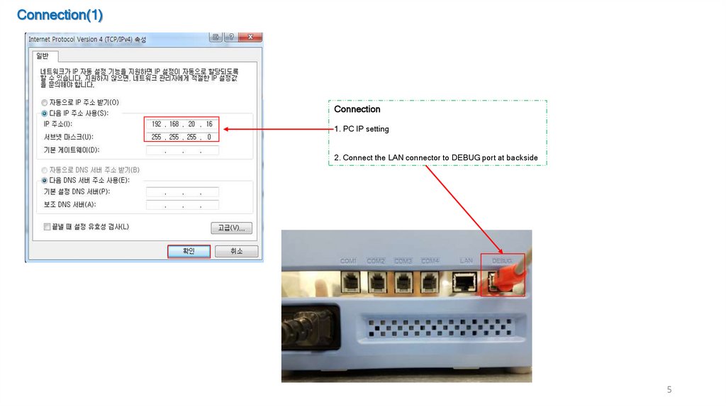
Connection(1)Connection
1. PC IP setting
2. Connect the LAN connector to DEBUG port at backside
5
6.
Connection(2)Connection
1
Click the “Connect” button
2
Waiting until the window pops up as shown below.
3
Connection Successful if Connected Lights Are Green as shown below
2. Waiting Dialog
4. Description for Lan Connection Status
Status of Connection
LAN
LAN connection success indicator
RP
RP loading success indicator
RPC
RPC loading success indicator
NMS
NMS loading success indicator
3. Lan Connection Status
Connected
Not-Connected
6
7.
Description – IRT/IRRChange Setting Values of IRT
1
2
3
4
1
Apply the changing value
2
Display the denomination
3
Display the IR value
4
Display the Threshold value
Reference
Condition for IRT/IRR reject
Process Result value < Threshold = Reject
Process Result value > Threshold = Accept
e.g)
Process Result Result = IR1 : 55
Threshold
= IR1 : 80
----------------------------------------------Rejected
7
8.
Description – Env MainDescription – Environment Main
1
1
2
3
4
2
3
5
6
7
CIS Ref Value
- The brightness value of images when images acquisitions
Image Skip Area
- Skip area setting value for the Full image when extracting the outline of the bank-note
Recognition Distance
- Recognition threshold value of bank-note
Max : Max threshold
Min : Min threshold
* If “Distance 1st" value from the processor result is over the Max threshold,
System will process "Not Match Denom" .
* If “Distance Final" value from the processor result is under the Min threshold,
System will process “Too Close Candidate" .
4
Breakage
Breakage Out Skip : Skip area value when system processes breakage detection.
DogEar Threshold : Classification setting value for DogEar & Missing Corner
Note Size Margin : Allowable margin for measurement of note size after complete
recognize denomination
5
Verify Defnomination
- Setting values for Old/New classification after recognition
6
US/IR/VLT Double
- Setting values for Double note detection.
7
Size Margin
- Allowable margin of note size when Mix & Auto Currency function operates
8
9.
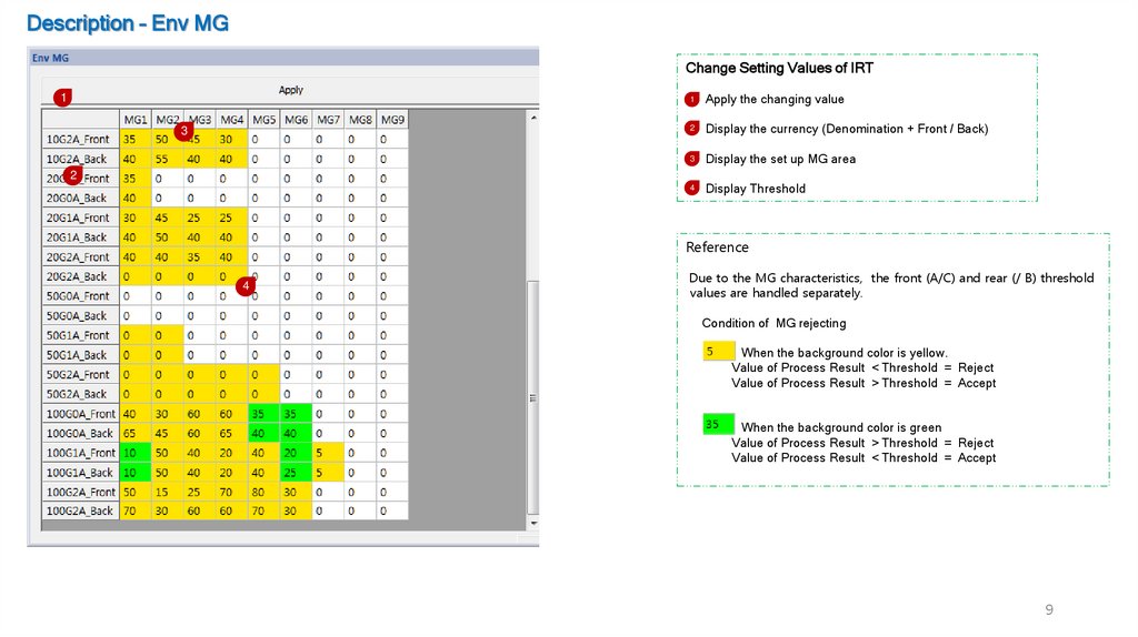
Description – Env MGChange Setting Values of IRT
1
3
1
Apply the changing value
2
Display the currency (Denomination + Front / Back)
3
Display the set up MG area
4
Display Threshold
2
Reference
4
Due to the MG characteristics, the front (A/C) and rear (/ B) threshold
values are handled separately.
Condition of MG rejecting
When the background color is yellow.
Value of Process Result < Threshold = Reject
Value of Process Result > Threshold = Accept
When the background color is green
Value of Process Result > Threshold = Reject
Value of Process Result < Threshold = Accept
9
10.
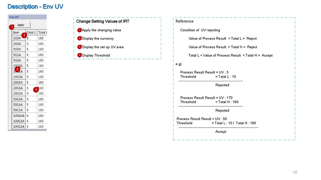
Description – Env UVChange Setting Values of IRT
1
1 Apply the changing value
3
Reference
Condition of UV rejecting
2 Display the currency
Value of Process Result < Total L = Reject
3 Display the set up UV area
Value of Process Result > Total H = Reject
4 Display Threshold
Total L < Value of Process Result < Total H = Accept
e.g)
2
Process Result Result = UV : 5
Threshold
= Total L : 10
------------------------------------------------------Rejected
4
Process Result Result = UV : 170
Threshold
= Total H : 160
------------------------------------------------------Rejected
Process Result Result = UV : 50
Threshold
= Total L : 10 / Total H : 160
-------------------------------------------------------------------Accept
10
11.
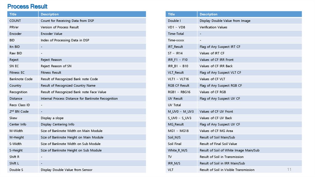
Process ResultTitle
Description
Title
Description
COUNT
Count for Receiving Data from DSP
Double I
Display Double Value from Image
PRVer
Version of Process Result
VD1 ~ VD8
Verification Values
Encoder
Encoder Value
Time-Total
-
BID
Index of Processing Data in DSP
Time-xxxxx
-
Itn BID
-
IRT_Result
Flag of Any Suspect IRT CF
Raw BID
-
ST ~ IR14
Values of IRT CF
Reject
Reject Reason
IRR_F1 ~ F10
Values of CF IRR Front
SN EC
Reject Reason of SN
IRR_B1 ~ B10
Values of CF IRR Back
Fitness EC
Fitness Result
VLT_Result
Flag of Any Suspect VLT CF
Banknote Code
Result of Recognized Bank note Code
VLT1 ~ VLT16
Values of CF VLT
Country
Result of Recognized Country Name
RGB CF Result
Flag of Any Suspect RGB CF
Recognition
Result of Recognized Bank note Face Value
RGB1 ~ RBG16
Values of CF RGB
Distance
Internal Process Distance for Banknote Recognition
UV Result
Flag of Any Suspect UV CF
Reco Class ID
-
UV Total
2nd BN Code
-
M_UV0 ~ M_UV3
Values of CF UV Front
Skew
Display a slope
S_UV0 ~ S_UV3
Values of CF UV Back
Center Info
Display Centering Info
MG_Result
Flag of Any Suspect UV CF
M-Width
Size of Banknote Width on Main Module
MG1 ~ MG18
Values of CF MG Area
M-Height
Size of Banknote Height on Main Module
Soil_M/S
Result of Soil Main/Sub
S-Width
Size of Banknote Width on Sub Module
Soil Final
Result of Final Soil Value
S-Height
Size of Banknote Height on Sub Module
White_R_M/S
Result of Soil of White Image Main/Sub
Shift R
-
TV
Result of Soil in Transmission
Shift L
-
IRR_M/S
Result of Soil in IRR Main/Sub
Double S
Display Double Value from Sensor
VLT
Result of Soil in Visible Transmission
11
12.
Process ResultTitle
Description
VL_R/G/B_M/S
Result of Soil in R/G/B Main/Sub
StF1 ~ StF8
Result of Stain Front 1 ~ 8
StB1 ~ StB8
Result of Stain Back 1 ~ 8
DeF1 ~ DeF8
Result of Deinked Front 1 ~ 8
DeB1 ~ DeB8
Result of Deinked Back 1 ~ 8
Brkg Cnt
Display Quantity of Detected Breakage
MC
Result of Missing Corner
Tear
Result of Tear
Hole
Result of Hole
DogEar
Result of Dog Ear
Oil
Result of Oil
Hologram
Result of Hologram
Tape
Result of Tape value
SN Size
Shows Number of Serial
SN Result
Shows Final Result of Recognized SN
Left_SN
Shows Recognized SN on Left Side
Right_SN
Shows Recognized SN on Right Side
12
13.
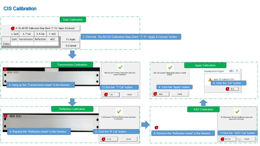
CIS CalibrationDark Calibration
1
1. Click the “Do All CIS Calibration Step (Dark / T / R / Apply & Cancel)” button
Transmission Calibration
Apply Calibration
2
2. Hang up the “Transmission sheet" in the Newton
9. Click the “OK” button
8. Click the “Apply” button
3.Click the “T Cal” button
3
9
8
Reflection Calibration
AGC Calibration
4
6
4. Replace the “Reflection sheet" in the Newton
5. Click the “R Cal” button
5
6. Remove the “Reflection sheet" in the Newton
7.Click the “AGC Cal” button
7
13
14.
UV CalibrationUV Calibration Mode On
1
1.Click the “Cal Mode On/Off” Button (Changing to the green color & ON on the status bar )
UV Calibration
3 UV Calibration Success 창 확인
2
2. Put on the UV Sheet on center of hopper.
Newton will insert the UV sheet.
3. Click the “OK” button
UV Calibration Apply
6
4
5. Click the “OK” button
5
14
15.
US CalibrationUS Calibration Mode On
1. Click the “Cal Mode On/Off” button (Changing to the green color & ON on the status bar )
1
2
2. Click the “OK” button
US Calibration
3
3. Put on the US Sheet on center of hopper.
Newton will insert the US sheet.
US Calibration Apply
US Calibration Success Check
7. Check the status bar
5. Click “Apply US Calibration” button
4. Click the “OK” button
5
7
6
4
6. Click the “OK” button
15
16.
MG CalibrationMG Calibration Sequence
1
3
2
4
5
1
Mark the “Start MG Calibration” .
2
Put on the MG Calibration Sheet .
3
Waiting the Warning Messages display.
4
If do not showing Warning Message , Click the “Apply” button.
6
Components Description
7
1
Enable/Disable Calibration mode
2
Cancel the Calibration
3
Apply the Calibration value
A4 Allowable maximum noise value
5
Value after Calibration
I 6 Inserted sheet image and MG position
7
Acquired MG data graph
16
17.
Usage – Floating and Docking DialogsThe adjustment program provides window screen for changing multiple
settings.
Various types of setup values are provided simultaneously to provide a
docking function.
The following figures are used for the use of docking windows.
1
Docking window on top
1
2
3
2
3
Docking Dialog
4
2
Docking window leftside
4
Docking window downside
3
Docking window rightside
17
18.
Trouble Shooting Guide- Reco Kisan Electronic R&D
2017 10 26
19.
Trouble Shooting1
Trouble. When there is a high IRT/IRR rejection? (Suspect IRT/IRR).
Solution 1. Remove dust on the CIS.
Solution 2.1. Check the IRT/IRR image using Test-Note
2.2. If the image is abnormal, Try CIS calibration.
Trouble. When there is a high MG rejection(Suspect MG)
Solution 1. Remove dust on the MR sensor.
Solution 2.1. Check the MG graph using Test-Note & ADJ SW
2.2. If the MG graph is abnormal, Try MG calibration.
2.3. If the MG graph is abnormal, Try to check GAP between sensor and roller.
Trouble. When there is a high IRT/IRR rejection in certain bank-note(Suspect IRT/IRR)
Solution 1.1. Connect ADJ SW with Newton
1.2. Check the IR value of Process Result( 1 )
1.3. Check the value of IR and IR Number( 2 )
1.4. Setting -> Click the “IRT or IRR”
1.5. Apply changing value of IR ( 3 )
Trouble. When there is a high MG rejection in certain bank-note(Suspect MG)
Solution 1.1. Connect ADJ SW with Newton
1.2. Check the MG value of Process Result ( 1 )
1.3. Check the value of MG and MG Number( 2 )
1.4. Setting -> Click the “Env MG”
1.5. Apply changing value of MG front or back ( 3 )
1
2
2
3
3
19
20.
Trouble ShootingTrouble. When there is a high UV rejection (Suspect UV)
Solution 1. Remove dust on the UV sensor
Solution 2.1. Check the UV graph using Test-Note & ADJ SW
2.2. If the UV graph is abnormal, Try UV calibration
Trouble. When there is a high UV rejection in certain bank-note (Suspect UV)
Solution 1.1. Connect ADJ SW with Newton
1.2. Check the UV Total value of Process Result ( 1 )
1.3. Setting ->Click the “ Env UV”
1.4. Apply changing value of UV ( 2 )
Trouble. When there is a high Double rejection (Double)
Solution 1. Remove dust on the US sensor .
Solution 2.1. Check the US graph using US Calibration sheet & ADJ SW
2.2. If the US graph is abnormal, Try US calibration
Trouble. When there is a high Double rejection in certain bank-note(Double)
Solution 1.1. Connect ADJ SW with Newton
1.2. Check the US Double S value of Process Result ( 1 )
1.3. Setting -> Click the “Env Main”
1.4. Apply changing value of US Double ( 2 )
1
1
2
2
20
21.
Trouble ShootingTrouble. When there is a lot of Pre-processing image error
Solution 1. Remove dust on the CIS.
Solution 2. Check the GAP of insert module using Test-Note
Solution 3. Adjust the GAP for insert module.
(- direction or + direction , P1.1 See picture below)
Solution 4. Check the skew using Test-Note. & newton APL
Solution 5. Update the currency SW again using USB.
Trouble. When there is a lot of denomination recognizing error(Reference F1.2)
Solution 1. Remove dust on the CIS.
Solution 2. Check the image using Test-Note.
Solution 3. If the image is abnormal, Try CIS calibration
Solution 4. Update the currency SW again using USB.
Trouble. When a US calibration fails ?
Solution 1. Remove dust on the US module and Try again
Solution 2 Try again changing the new US Calibration Sheet.
Solution 3. Replace the US sensor PCB
Trouble. When a MG calibration fails ?
Solution 1. Remove dust on the MR module and Try again
Solution 1. Try again changing the new MG Calibration Sheet.
Solution 3. Replace the MR sensor module
Trouble. When a CIS calibration fails
Solution 1. Remove dust on the CIS.
Solution 2. Try again changing the new CIS Calibration Sheet.
Solution 3. Check the fail point and replace the new CIS module.
Trouble. When a UV calibration fails
Solution 1. Remove dust on the UV module.
Solution 2. Try again changing the new UV Calibration Sheet .
Solution 3. Check the fail point and replace the new UV module PCB
F1.1 Pre-processing error
mage #0 Parallel Lines Error
Image #1Parallel Lines Error
Image #0 Apexs out of range Error
Image #1 Apexs out of range Error
Image #0 Overflow into range Error
Image #1 Overflow into range Error
Image #0 Too little edge data Error
Image #1 Too little edge data Error
Image out of scan area Error Top
Image out of scan area Error Bottom
Image out of scan area Error Left
Image out of scan area Error Right
Find Image Centering Info Error
F1.2 Denomination recognizing error
Not Match Denom
Too Close to Candidate
P1.1 투입구 조절 레버
Trouble. When there is in case of a continuous " Check CIS " message
Solution 1. Remove dust on the CIS.
Solution 2. Update the FPGA SW again using USB
Solution 3. Update the APL SW again using USB
Solution 4. Update the DSP SW again using USB
Trouble. When alert window does not disappear after removal of JAM
Solution 1. Try again open/close Main Cover & Back Cover
Solution 2. Update the Mecha SW again using USB
Solution 3. Replace the IR sensor PCB
21
22.
Appendix - DSP Log Access1.
2.
3.
4.
5.
Terminal 또는 Tera Term 등의 시리얼 통신 프로그램을 실행한다.
Port 설정 후 Baud Rate : 115200으로 세팅한다.
Terminal 창에서 Enter Key 입력 시 “C6748>” 출력 확인
지폐 계수 시 Log 출력 확인( 1 )
DSP Log Data 요청 시 출력 Text를 저장하여 발송
1
23.
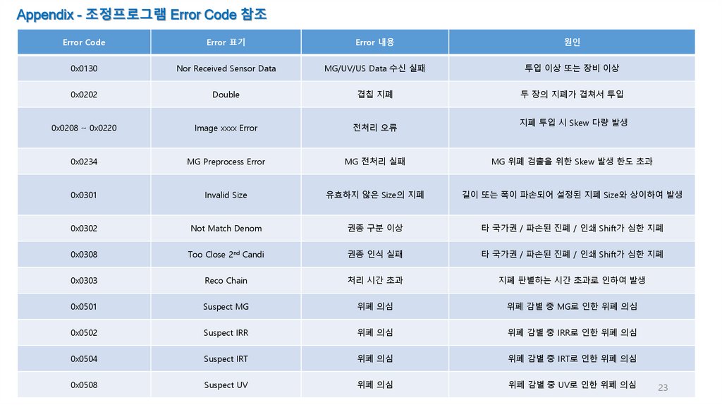
Appendix - 조정프로그램 Error Code 참조Error Code
Error 표기
Error 내용
원인
0x0130
Nor Received Sensor Data
MG/UV/US Data 수신 실패
투입 이상 또는 장비 이상
0x0202
Double
겹칩 지폐
두 장의 지폐가 겹쳐서 투입
0x0208 ~ 0x0220
Image xxxx Error
전처리 오류
0x0234
MG Preprocess Error
MG 전처리 실패
MG 위폐 검출을 위한 Skew 발생 한도 초과
0x0301
Invalid Size
유효하지 않은 Size의 지폐
길이 또는 폭이 파손되어 설정된 지폐 Size와 상이하여 발생
0x0302
Not Match Denom
권종 구분 이상
타 국가권 / 파손된 진폐 / 인쇄 Shift가 심한 지폐
0x0308
Too Close 2nd Candi
권종 인식 실패
타 국가권 / 파손된 진폐 / 인쇄 Shift가 심한 지폐
0x0303
Reco Chain
처리 시간 초과
지폐 판별하는 시간 초과로 인하여 발생
0x0501
Suspect MG
위폐 의심
위폐 감별 중 MG로 인한 위폐 의심
0x0502
Suspect IRR
위폐 의심
위폐 감별 중 IRR로 인한 위폐 의심
0x0504
Suspect IRT
위폐 의심
위폐 감별 중 IRT로 인한 위폐 의심
0x0508
Suspect UV
위폐 의심
위폐 감별 중 UV로 인한 위폐 의심
지폐 투입 시 Skew 다량 발생
23