


 Электроника
 Промышленность
Похожие презентации:


Shanghai WTL Welding Equipment
1.
MAGIC AC GTIG-200PShanghai WTL Welding Equipment
Manufacture Co.Ltd
March.2018
2.
Catalogue1、Introduction of working principle
2、Introduction of main circuit
3、Introduction of control circuit
4、Introduction of panel circuit
5、Troubleshooting
6、Component test
3.
1、Introduction ofworking principle
4.
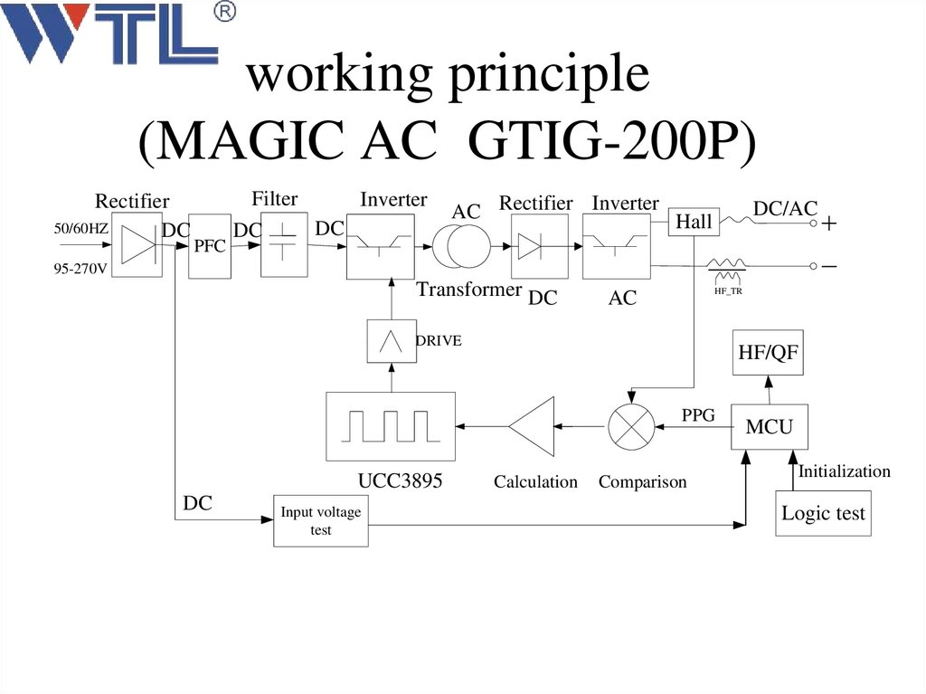
working principle(MAGIC AC GTIG-200P)
Rectifier
50/60HZ
DC
PFC
Filter
Inverter
DC
DC
AC Rectifier Inverter Hall
DC/AC
95-270V
Transformer DC
HF_TR
AC
DRIVE
HF/QF
PPG
UCC3895
DC
Input voltage
test
Calculation
Comparison
MCU
Initialization
Logic test
5.
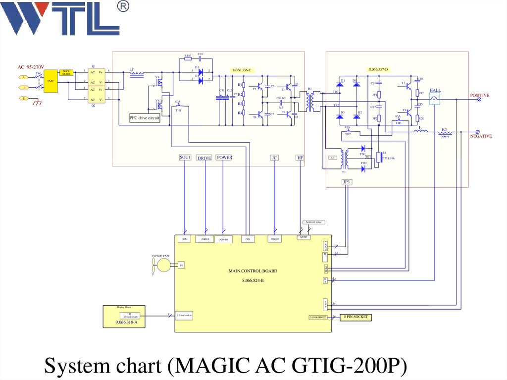
C10R187
Q1
AC 95-270V
SOFT
START
SW1
1
AC
V+
4
D3
LT
1
V8
A
EMC
2
B
1
E
2
AC
V-
AC
V+
AC
V-
1
3
8.066.337-D
8.066.336-C
2
AK
D4
2
AK
D1
R1
4
T5
C11 C12
T7
C26
B1
T3
TR1
C2 R2
3
C10
D4
C6
C5
R12
JP1
HALL
POSITIVE
C61/62
V8-1
80A
R3
Q2
TH1
R4
3uF
T6
C7
C15
C27
D3
T8
D2
C8
T4
PFC drive circuit
TR2
85A
JP2
R28
TH3
85A
L
TH2
SOU1
DRIVE
NEGATIVE
FD1
POWER
JC
HF
AC
L1
DC
7.731.146
FD2
T1
JP3
Solenoid Valve
SOU
8
DRIVE
2
3
POWER
OT1
110/220
2
QF/HF
MAIN CONTROL BOARD
W
A
WVIN
8.066.824-B
OT2
P1
F
Display Board
12
3
2
J8
DC24V FAN
J1
12-lead socket
2
ACPOUT
2
12-lead socket
GUN/REMOTE
4
2
5
B2
8 PIN SOCKET
9.066.318-A
System chart (MAGIC AC GTIG-200P)
6.
Explosive drawing7.
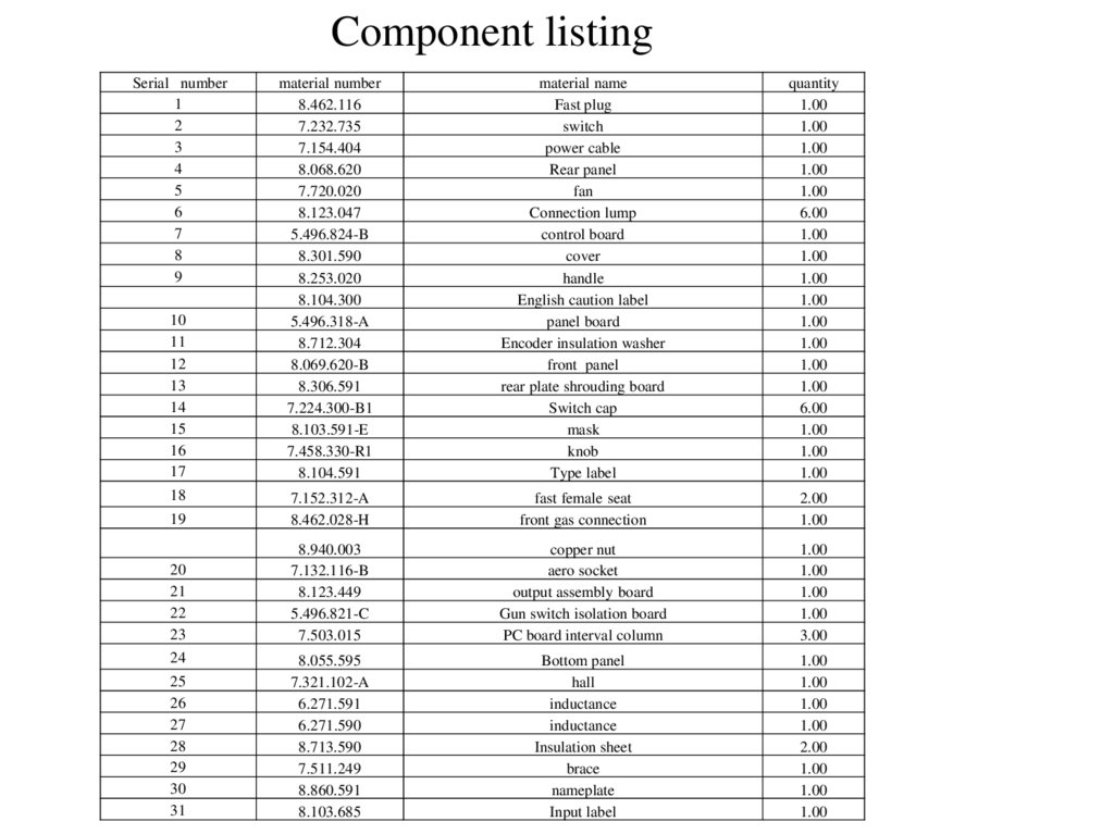
Component listingSerial number
1
2
3
4
5
6
7
8
9
material number
8.462.116
7.232.735
7.154.404
8.068.620
7.720.020
8.123.047
5.496.824-B
8.301.590
8.253.020
8.104.300
5.496.318-A
8.712.304
8.069.620-B
8.306.591
7.224.300-B1
8.103.591-E
7.458.330-R1
8.104.591
material name
Fast plug
switch
power cable
Rear panel
fan
Connection lump
control board
cover
handle
English caution label
panel board
Encoder insulation washer
front panel
rear plate shrouding board
Switch cap
mask
knob
Type label
quantity
1.00
1.00
1.00
1.00
1.00
6.00
1.00
1.00
1.00
1.00
1.00
1.00
1.00
1.00
6.00
1.00
1.00
1.00
19
7.152.312-A
8.462.028-H
fast female seat
front gas connection
2.00
1.00
20
21
22
23
8.940.003
7.132.116-B
8.123.449
5.496.821-C
7.503.015
copper nut
aero socket
output assembly board
Gun switch isolation board
PC board interval column
1.00
1.00
1.00
1.00
3.00
8.055.595
7.321.102-A
6.271.591
6.271.590
8.713.590
7.511.249
8.860.591
8.103.685
Bottom panel
hall
inductance
inductance
Insulation sheet
brace
nameplate
Input label
1.00
1.00
1.00
1.00
2.00
1.00
1.00
1.00
10
11
12
13
14
15
16
17
18
24
25
26
27
28
29
30
31
8.
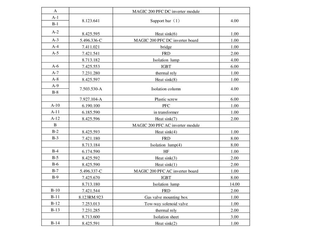
AA-1
B-1
A-2
A-3
A-4
A-5
A-6
A-7
A-8
A-9
B-8
A-10
A-11
A-12
B
B-2
B-3
B-4
B-5
B-6
B-7
B-9
B-10
B-11
B-12
B-13
B-14
MAGIC 200 PFC DC inverter module
8.123.641
Support bar 1
4.00
8.425.595
5.496.336-C
7.411.021
7.421.541
8.713.182
7.425.553
7.231.280
8.425.597
Heat sink(6)
MAGIC 200 PFC DC inverter board
bridge
FRD
Isolation lump
IGBT
thermal rely
Heat sink(8)
1.00
1.00
1.00
2.00
4.00
6.00
1.00
1.00
7.503.530-A
Isolation column
4.00
7.927.104-A
6.190.100
6.185.590
8.425.596
Plastic screw
PFC
in transformer
Heat sink(7)
MAGIC 200 PFC AC inverter module
Heat sink(4)
FRD
Isolation lump(4)
HF
Heat sink(3)
Heat sink(1)
MAGIC 200 PFC AC inverter board
IGBT
Isolation lump
FRD
Gas valve mounting box
Tow-way solenoid valve
thermal rely
Isolation sheet
Heat sink(2)
6.00
1.00
1.00
2.00
8.425.593
7.421.180
8.713.184
6.174.590
8.425.592
8.425.590
5.496.337-C
7.425.670
8.713.180
7.421.544
8.123RM.923
7.253.013
7.231.285
8.713.600
8.425.591
1.00
8.00
8.00
1.00
2.00
2.00
1.00
8.00
14.00
2.00
1.00
1.00
2.00
3.00
1.00
9.
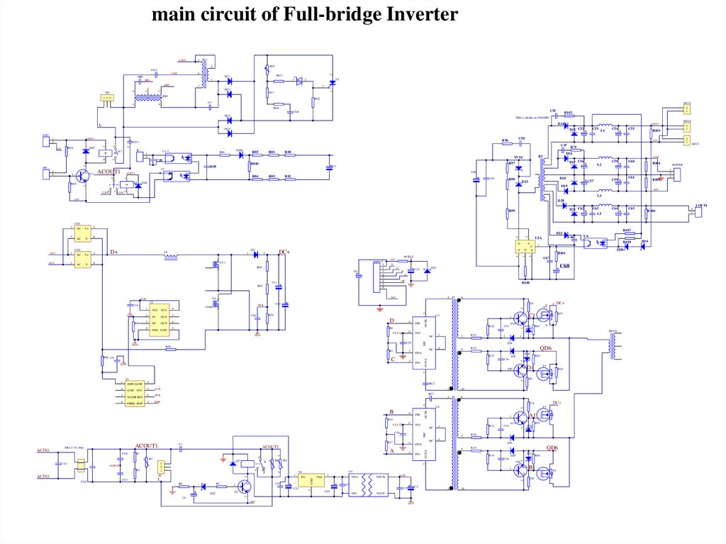
2、Introduction of main circuit10.
main circuit of Full-bridge Inverter5 TG1
5
HF1
1
RG3
V1
1
1
2
3
3
DG2
5
3
3
DG1
V2
G
LG1
45
THF
RG2
C3
4
1
1
2
3
12
KG
3
2
HF2
RG1
2
4
2
4
HFC
1 2
2
110V
1
220V
CG2
SOU3
RG4
C51
CG4
DG3
2
1
R102
VRD is disable on TIG/MIG
SOU2
D14
L
+24V1
D15 C52
DG4
1
2
U1-2
1
2
R08
2
220V
R00
1
K2
21
110V
D17 C56
C58
C60
R104
L2
R02
C49
D18
R98
C61
C59
C57
D13
DG6
SOU1
POWER
1
2
3
C48
R03
2
1
R71
C7
R04
2
1
R103
+24V
R97
R010
R09
C55
D16
B3
TVS1
U7
C54
R105
D19
-24V
2
7
3
RG5
R01
+24V1
7
5
3
E
B
R05
C18
ACOUT1
V3
5
1
3
1
2
C
HF
ZD02
L1
+01
C47
JC
C53
C50
R96
CG1
K1
2
4
43
DG5
3
RG6
+01
1 2
+24V1
21
1
2
1
SOU
L3
+01
D20
D21 C62
R99
C63
L5
C64
C65
J-OUT1
R106
UD1
1
AC
V+
AC
V-
2
R107
R108
D
R64
C6
C11
R65
V8
+UB
U2
INB
R8
5
6
VCC
R26
VCC
NC
C28
R50
R9
R46 C4
3
1
7
R25
C33
2
2
QD6
NC
8
9
C
2
4
6
ACOUT2
INB
D2
J1
R5
MIC
2
NC
7
R20
9
R18
C35
V39
R19
V40
B
C21
VIN+
VOUT+
VIN-
VOUT-
+UB
-24V
B
2
GND
2
2
2
T6
C
1
E
R7
ZD2
C8
3
C5
C2
C19
C29
3
R6
Vout
QD6
1
10
R94
B1
C
4
5
1
Vin
QD6
ZD3
D29
C36
U9
V4
1
C25
R93
ZD6
D28
R4
L
A1
B
8
GND
INA
T3
2
R21
1
7
3
2
1
AC
CU3
A
DC+
GA
1
VCC
6
R3
CU2
3
1
R1
R2
8
OUTA
R11
C1
ACOUT1
GDN
10
2 T8
U4
NC
CU1
1
C
BOP
E
2
5
C30
ACIN2
R24
GD
RC1
3
VFB
VCC
CU4
T2
1
+UB
6
R10
TR1(7.731.506)
R92
RC2
7
B
ACIN1
3
ZBYQ
1
FREQ BOP
R91
D1
E
2
ICOMVSEN
F
C
B
7
GND VCC
5
4
ISEN GATE
R27
S
QD6
ZD5
D26
C34
OUTB
3
DC+
G
R22
U1
8
2
D24
V37
1
2
ZD4
1
GND
INA
C11
B
V38
2 1
R23
C
1
D
T1
2
4
1
E
2
D
6
U3
3
R59
C20
AK
7
QD6
QD6
5
GC
8
1
GND GND
8
1
OUT
R100
2 T7
3
4
NC
A
OC
KA
3
OUT
C68
ZD7
C32
B
E
2
R48
IN
C
AK
2
D
5
VCC VCC
C67
15V
C12
VFB
1
QD6
IMOUT
1
2
3
4
5
6
7
8
-24V
C14
ZD8
R101
R12VCC
V8-1
4
X
S
DC+
2
AK
4
1
3
D4
LT
3
V-
D+
KA
AC
2
OUTB
3
V+
MIC
AC4
AC
OUTA
1
U6
1
C
UD2
AC3
C66
U5A
L
6
4
2
D22
3
GB
T4
ZD9
2
1
11.
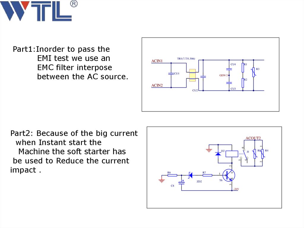
Part1:Inorder to pass theEMI test we use an
EMC filter interpose
between the AC source.
TR1(7.731.506)
ACIN1
CU4
R1
R3
CU1
GDN
R2
ACIN2
CU3
CU2
6
1
ACOUT2
D2
R5
R7
ZD2
C8
1
T6
B
E
R6
C
2
2
4
5
J1
3
Part2: Because of the big current
when Instant start the
Machine the soft starter has
be used to Reduce the current
impact .
-24V
R4
12.
PFC technology=greenpower energy
P=UI cosφ
cosφ=0.99
High power efficiency
Global input voltage:95V---270V
Avoid input voltage fluctuant
13.
PFC chip and theory• ICE3PCS03G(see the PDF document)
• Power input : 95V 270VAC
• PFC output: 360(working) 385(open circuit)
VDC
14.
1PFC theory: Boost
Inductance
Diode
4
2
Main
DC
capacitor
output
IGBT
3
AC input
Rectifier
PFC chip control
15.
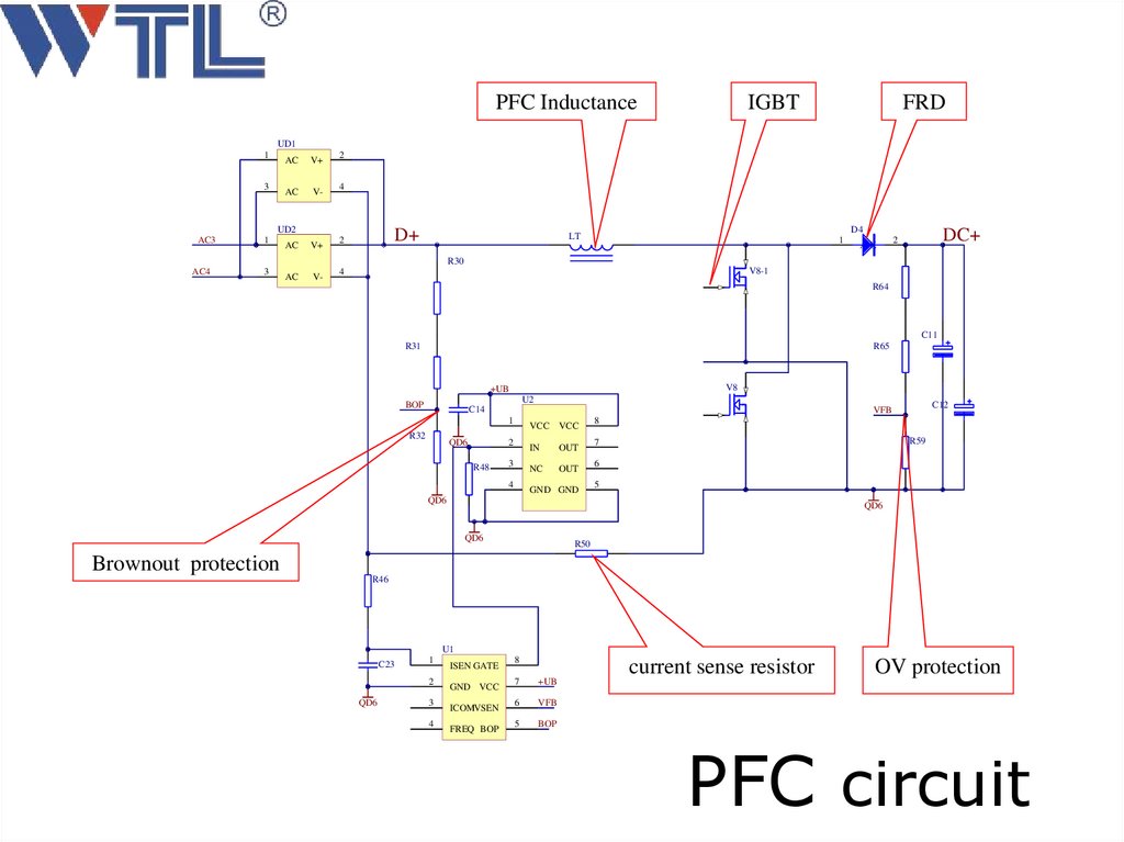
PFC InductanceIGBT
FRD
UD1
1
3
AC
V+
AC
V-
2
4
UD2
AC3
1
AC
V+
AC
V-
D+
2
D4
LT
1
AK
DC+
2
R30
AC4
3
V8-1
4
R64
C11
R31
R65
V8
+UB
U2
BOP
C14
R32
QD6
VCC VCC
2
R48
C12
VFB
1
IN
3
NC
4
OUT
OUT
GND GND
8
R59
7
6
5
QD6
QD6
QD6
R50
Brownout protection
R46
U1
C23
1
2
QD6
3
4
ISEN GATE
GND VCC
ICOMVSEN
FREQ BOP
8
7
+UB
6
VFB
5
BOP
current sense resistor
OV protection
PFC circuit
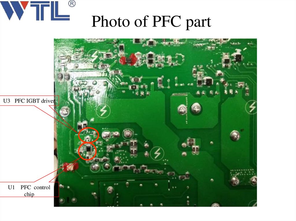
16.
Photo of PFC partU3 PFC IGBT driver
U1 PFC control
chip
17.
The location of PFC IGBT18.
Preparation of test PFC IGBT1、We must Switch off the machine
2、After 5 minutes we can test .
3、Turn the rotary switch to test diode.
4、keep 3 seconds when we test every step.
5、If the result we test as similar as the following
picture .we can say the IGBT is good. Otherwise
there are some IGBT damaged.
19.
PFC IGBT Test(A-1)PFC IGBT Test(A-2)
20.
PFC IGBT Test(A-3)PFC IGBT Test(A-4)
21.
PFC IGBT Test(A-5)PFC IGBT Test(A-6)
22.
Solutions when the IGBT is damaged1、 Check the circuit of PFC IGBT driver may
be there are some components damaged.
2、Remove IGBT one by one and test as
following page.
3、Replace IC TC4420.
4 、 Replace PFC control chip ICE3PCS03G .
23.
2 T78
GC
C28
3
C
7
R25
2
C
E
2
3
1
2 1
NC
8
9
INA
R91
S
3
ZBYQ
QD6
R22
GND
R23
2
R27
D24
ZD5
D26
C34
OUTA
R9
1
MIC
NC
ZD4
AK
VCC
V38
DC+
G
1
6
C33
3
VCC
R26
KA
INB
R8
C11
B
E
2
4
1
OUTB
D
U3
2
1
5
2
D
T1
V37
1
T2
D1
R24
2
C
7
B
R92
GD
RC2
1
10
2 T8
8
RC1
2
NC
2
R20
9
R18
C
E
2
R93
AK
ZD6
D28
GND
INA
V39
R19
QD6
ZD3
D29
C36
V40
7
A
3
7
C35
8
OUTA
R11
MIC
C30
R21
1
B
R94
B1
T4
2
C
1
KA
NC
3
VCC
A1
B
1
6
1
1
VCC
T3
E
2
INB
R10
3
5
4
OUTB
B
DC+
GA
U4
1
10
GB
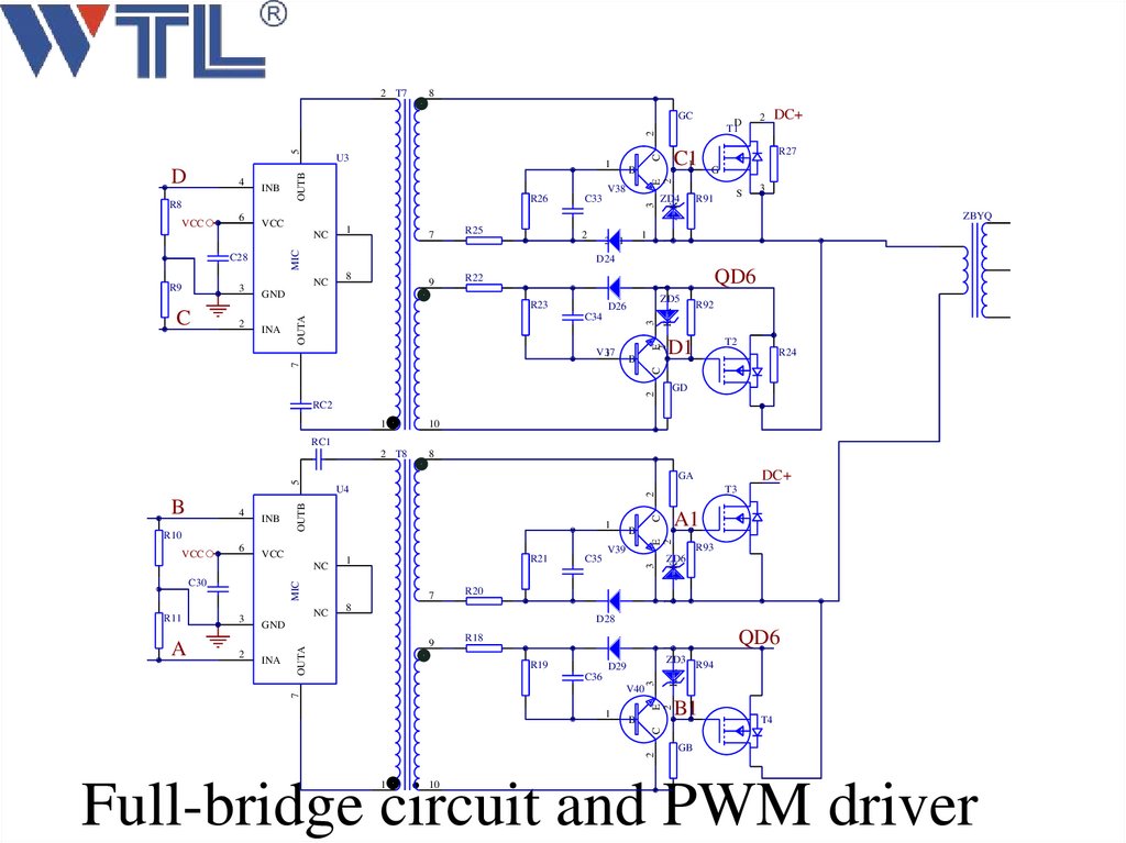
Full-bridge circuit and PWM driver
24.
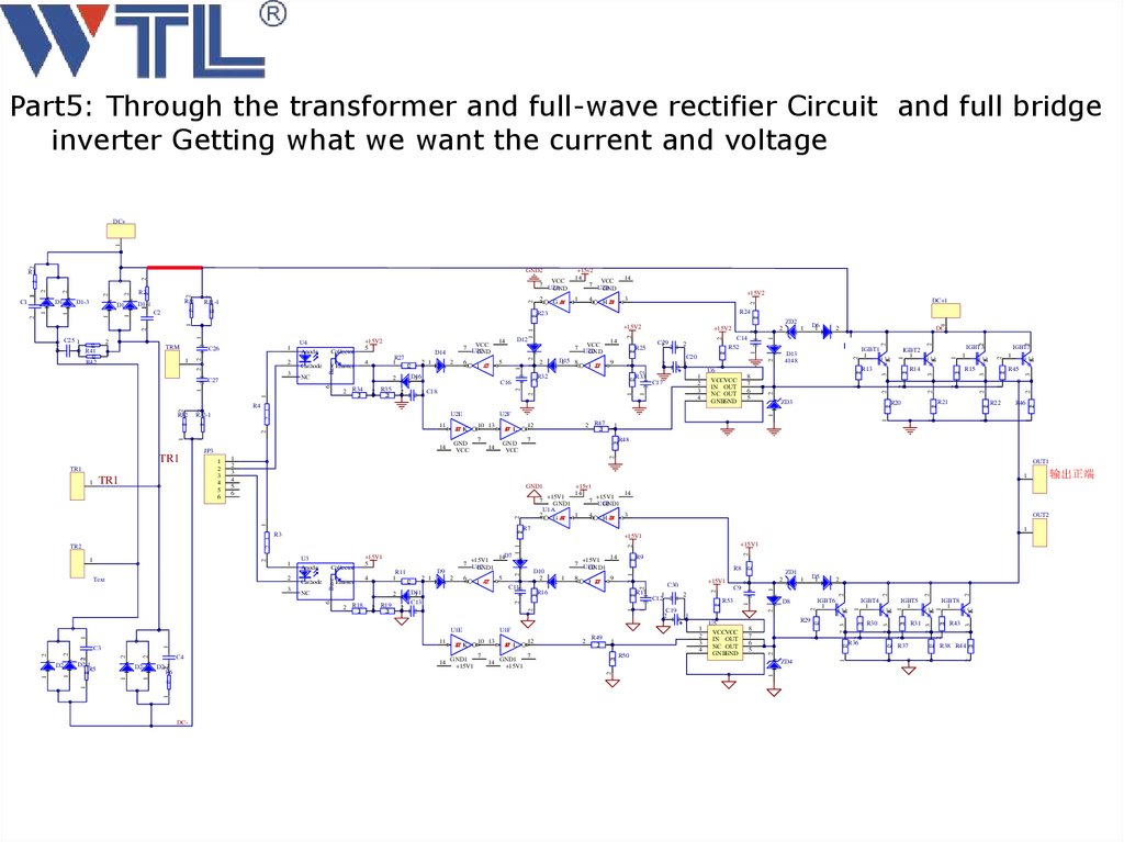
Part5: Through the transformer and full-wave rectifier Circuit and full bridgeinverter Getting what we want the current and voltage
2
E K
GND
VCC
10 13
2
1
1
12
2
2
EC
3
2
EC
G
R45
1
2
1
R22
R46
12
2
2
R21
1
1
1
1
12
12
R20
IGBT7
12
G
R15
2
2
ZD3
1
3
1
21
R14
3
21
3
IGBT3
2
1
8
7
6
5
12
R13
U6
VCCVCC
IN OUT
NC OUT
GNDGND
G
EC
IGBT2
1
1
EC
2
2
1
2
D13
4148
2
1
12
A K
2
2
12
2
DC+
IGBT1
1
G
1
2
+15v1
14
14
+15V1
+15V1
7
7 U1B
GND1
GND1
U1A
2
1
4
3
GA
HB
1
OUT2
R7
12
1
12
1 3
G
EC
2
2
R43
R38 R44
21
2
12
R37
21
EC
1
IGBT8
1
2 3
1
R31
G
2
12
R36
IGBT5
1
21
2 3
EC
2
2
1
EC
21
2 3
2
12
2
A K
ZD4
2
2 1
2
1
R30
G
1
R50
IGBT4
1
1
1
G
2
R49
21
8
7
6
5
2
12
2
U5
VCCVCC
IN OUT
NC OUT
GNDGND
K A
IGBT6
1
1
7
D8
1
12
1
2
3
4
D5
1
1
R29
K A
F L
GND1
14
+15V1
R53
A K
2
7
2
GND1
14
+15V1
U1F
10 13
C19
2
1
1 2
ZD1
2
1
E K
1
2
C12 2 1
12
R17
C9
1
R16
+15V1
C30
12
12
R9
R8
9
2
J D
14
2 1
A K
8
1
C11
+15V1
7 U1D
GND1
1
2
2
D10
2
12
D11
1
A K
C13
21
1
1 2
+15V1
2 1
A K
1 2
5
1
I C
14D7
1
21 R19
21
K A
6
1
2 R18
21
12
2
21
2
+15V1
7 U1C
GND1
D9
2 1
1 2
R11
1
4
21
NC
Emitter
+15V1
5
2
Cathode
Collector
2
U3
Anode
Base
1
+15V1
1 1
R3
6
2
12
1
DC-
2
R48
2
1
1
2
K A
1
2
K A
1
12
12
1
2 R47
21
7
GND
VCC
14
K A
GND1
2 1
1
2
2
K A
1
D2-3
R6
1
2
K A
1
D2-2
1
2
3
4
C17
D6
1
1
OUT1
11
D2-1
R5
R33
12
F L
7
U1E
D2
12
1 1
A K
1 2
R32
A K
1
3
C4
1 2
C20
1
U2F
1
2
3
4
5
6
2
Text
2
2 1
2
1
U2E
14
2
1
J D
9
C14
R52
2
K A
1 C18
JP3
A K
D15
1
8
R25
2 1
C16
2
+15V2
C29
1
1
1 2
5
14
1
21
11
1
2
3
4
5
6
I C
D16
1
A K
1
1
6
1
2
+15V2
VCC
7 U2D
GND
ZD2
21
21 R35
21
K A
2 1
1
1
2 R34
21
12
2 1
D12
14
DC+1
12
12
2
D14
12
2
12
2
R4
R27
1
4
VCC
7 U2C
GND
21
NC
Emitter
+15V2
5
1 2
C27
RJ2-1
TR1
C3
+15V2
R24
2
3
Cathode
Collector
6
2 1
2
RJ2
TR2
1
HB
2
1
C26
U4
Anode
Base
1
1
TR1
1
3
4
1
2
12
1
2
TR1
1
1
GA
1
1
1 2
TRM
2 2
2
2
R23
2
C25 1
12
2
1
1 R41
12
R42
14
1
2
2
RJ1-1
12
C2
+15v2
14
VCC
7 U2B
GND
2 1
2
12
RJ1
D1-1
1
2
1
D1
K A
2
K A
K A
1
D1-3
1
2
12
2
1
K A
D1-2
2
1
C1
R2
VCC
7 U2A
GND
12
GND2
R1
2
2
1
1
DC+
1
输出正端
25.
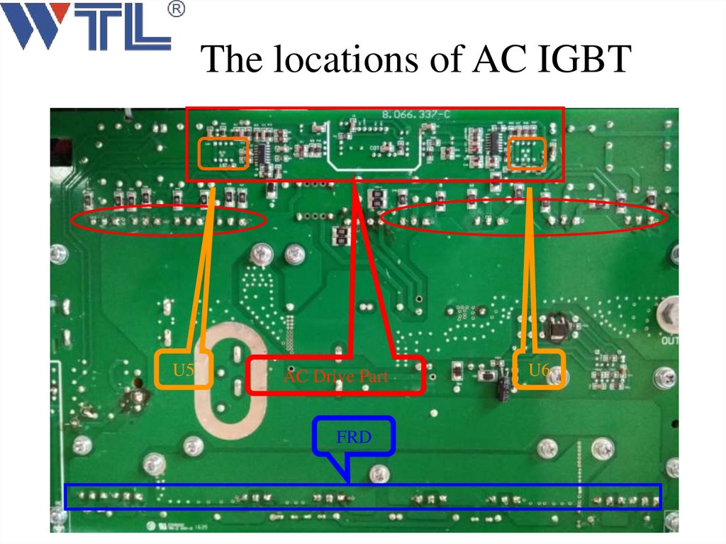
The locations of AC IGBTU5
AC Drive Part
FRD
U6
26.
Solutions when the IGBT is damaged1、 Check the circuit of AC IGBT driver may
be there are some components damaged.
2、Remove IGBT one by one and test as
following page.
3、Replace IC TC4420 and CD4066.
4 、Replace CNY17-4.
27.
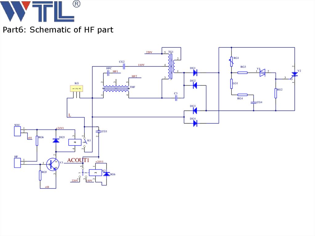
Part6: Schematic of HF part5 TG1
5
4
HF1
1
V1
1
3
5
DG2
LG1
RG2
C3
RG4
CG4
DG3
L
DG4
2
K1
2
4
CG1
2
1
DG5
21
RG6
43
+01
1 2
+24V1
3
1
2
1
SOU
ACOUT1
220V
+01
1
110V
21
7
5
3
7
RG5
+24V1
2
5
V3
E
B
3
1
3
1
2
C
HF
K2
DG6
2
3
45
3
3
RG3
DG1
1
THF
4
12
1
1
2
3
3
2
HF2
KG
4
2
110V
HFC
RG1
2
1 2
2
CG2
G
1
220V
V2
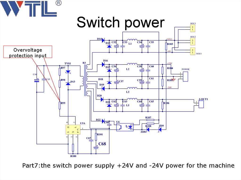
28.
Switch powerSOU3
2
1
SOU2
D14
+24V1
D15 C52
C53
L1
C54
C55
Overvoltage
protection input
2
1
+01
+24V
D17 C56
R97
C58
C60
R104
L2
D18
C61
C59
C57
D13
POWER
1
2
3
C48
R98
SOU1
D16
B3
TVS1
C49
2
1
R103
R105
D19
-24V
L3
D20
D21 C62
R99
2
L
6
D
C66
J-OUT1
R106
2
1
U6
ZD9
1
ZD8
F
X
C65
R108
C
S
C64
R107
D22
U5A
C63
L5
5
3
4
R101
C67
C68
R100
Part7:the switch power supply +24V and -24V power for the machine
29.
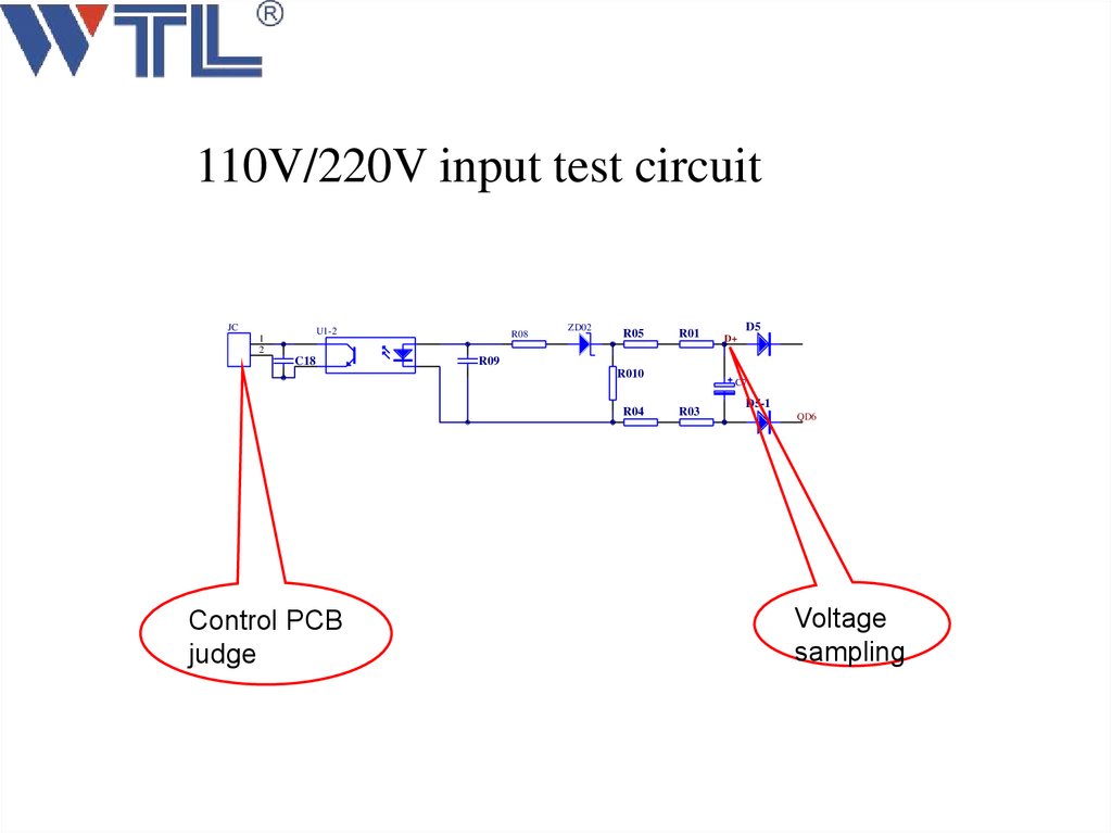
110V/220V input test circuitJC
U1-2
1
2
C18
R08
ZD02
R05
R01
R09
R010
R04
Control PCB
judge
D5
D+
C7
R03
D5-1
QD6
Voltage
sampling
30.
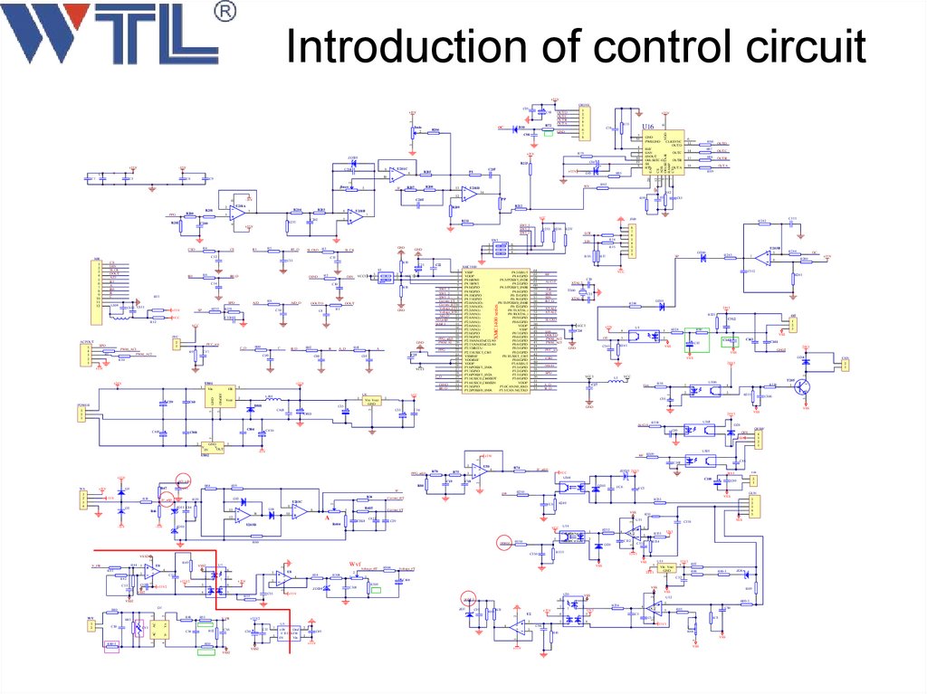
3、Introduction ofcontrol circuit
31.
Introduction of control circuit+15V
DRIVE
OC
R206
R72
D30
GND
U16
C78
5
16
GND
PWRGND
4
1
2
10
19
8
C204
U201C
9
R205
8
C1
R85
C9
3
R208
R207
IF
13
14
12
3
R202
7
VCC
5
C202
R217
4
C200
J300
R211
SW1_1
SW1_2
SW1_3
+15V
R235
R236
SOT
B1_D
R3
SLCKD
C12
MB
R6
B0_D
R2
DIND
3
4
VCC1
DIN
C14
2
1
VCC1
C10
SPD
C812 C811
+15V
R232
SP
R8
A/D
A/D_D
R231
R18
DOUTD
C16
DOUT
R1
C4
GND
C220
VCC
R12
VCC
PFC
ACPOUT
2
1
SPD
5
4
3
2
1
PWM_AC1
PWM_AC2
R7
GND
PFC_test
R00
C_D
R9
C
R02
B_D
C17
C09
B
R01
A_D
C00
A
C25
C01
R10
+15V
VCC1
U801
C60
3
3
2
1
4
FB
ON/OFF
GND
C59
POWER
+15V
Vin
Vout
U6
L801
2
1
D801
Vin Vout
GND
C35
C803
C22
D200
VSSP
VDDP
P4.6/HW0
P4.7/HW1
P4.8/GPIO
P4.9/GPIO
P4.10/GPIO
P4.11/GPIO
P2.0/AN(IO)
P2.1/AN(IO)
P2.2/AN(I)
P2.3/AN(I)
P2.4/AN(I)
P2.5/AN(I)
P2.6/AN(I)
P2.7/AN(I)
P2.8/GPIO
P2.9/GPIO
P2.10/AN(IO)/CCU40
P2.11/AN(IO)/CCU40
P2.12/BCCU
P2.13/USIC1_CH1
VSS/REF
VDD/REF
VDDP
P1.8/POSIF1_IN0A
P1.7/GPIO
P1.6/POSIF1_IN2A
P1.5/USIC0_CH0/SOT
P1.4/USIC0_CH0/SIN
P1.3/GPIO
P1.2/POSIF0_IN0A
64
63
62
61
60
59
58
57
56
55
54
53
52
51
50
49
48
47
46
45
44
43
42
41
40
39
38
37
36
35
34
33
P4.5/ERU1
P4.4/GPIO
P4.3/POSIF1_IN2B
P4.2/GPIO
P4.1/POSIF1_IN0B
P4.0/GPIO
P0.15/GPIO
P0.14/GPIO
P0.13/POSIF0_IN0B
P0.12/GPIO
P0.11(XTAL)
P0.10(XTAL)
P0.9/GPIO
P0.8/GPIO
VDDP
VSSP
P0.7/GPIO
P0.6/GPIO
P0.5/GPIO
P0.4/GPIO
P0.3/GPIO
P0.2/GPIO
P0.1/USIC1_CH1
P0.0/GPIO
P3.4/ERU1
P3.3/GPIO
P3.2/GPIO
P3.1/GPIO
P3.0/GPIO
VDDP
P1.0CAN.N0_RXD
P1.1/CAN.N0_TXD
C804
C20
AirCtrl
XTAL2
Fan
SOT
SIN
B1_D
T300
C23
XTAL1
D201
R248
24V1
XTAL1
XTAL2
R325
OT
C312
SLCKD
VCC1
+15V
C24
gun
DOUTD
PWM_AC2
PWM_AC1
4
OT
3
C
A
E
K
R324
1
1
2
3
R90
VSS
2
R141
C141
GND
PFC_test
U1
C143
C142
D204
24V1
remote
VCC1
A_D
B_D
VCC
L1
C27
R58
Fan
U306
1
2
A
C
K
E
GND
R316
4
3
R315
C410
QF/HF
C99
-15V
QF0
5
1
U50
R74
4
IF_adj0
ZD201 24V1
VCC
3
10
C313
VSS
C29
U14
VCC
4
R60
remote
R150
R252
1
Collector
LED Anode
3
4
2
Emitter
LED Cathode
D20
R151
C150
U15
7
3
6
4
5
1
7
3
+15V
Voltage_RT
U8
R54
4
VSS2
4
C55
R53
ZD204
R305
V_FB
C54
7
C97
R63 R31
+15V
R52
C56
C37
C30
7
5
+0V
Dnd
F1515S-1W
0V
Vin
4
2
C49
1
+15V
R50
VSS2
VSS2
U2
6
+15V2
U5
R67
R66
R66-1
+15V
1
5
C96
3
R45
8
7
ZD8
R69
VSS
U20
8
2
R51
15V1
3
C32
VSS
5
2
1
R48
V+
AC
AC
V4
CY1
3
R40-1
C301
ZD7
R43
Vin Vout
GND
24V1
pedal_I
D7
R40
C50
1
VSS
Voltage_FT
3
+15V
VSS2
1
2
R306
2
1
C404
6
5
R304
U13
VSS
Wvf
2
8
2
8
2
R154
VSS
1
1
R254
2
2
6
3
5
4
15V1
3
4
U12
C5
IN+
OUT
IN-
3
C5-1
4
R69-1
1
C90
R65
1
3
+15V2
1
15V1
15V1
2
+15V2
5
C52
2
V+ V-
C53
5
C51
U7
VSS2
1
4
VSS
C158
R153
V+ V-
R49
U0
R42
V+ V-
3
V+ V-
R44 1
R41
R70
1
IN+
OUT
3
INC152
C153
2
VSS2
V_FB
1
2
3
4
5
R253
R249
R404
U203D
ZD10
-15V
Current_FT
C413
5
-15V
Current_RT
R405
FC8
1
A
15V1
R71
1
8
14
12
GUN
VSS
2
2
R68
3
D14
13
2
1
FC5
R250
VSS
3
U203C
9
ZD11 C44
FC6
2
D13
R39
IF_adj0
gun
R34
C89
2
IF
R46
C100
D203
V+ V-
R38
D5
C18
R80
5
-15V
C45
R59
2
R47
D3
C19
R64
sou
24V1
U304
AD_adj0
WV
C88
C302
V- V+
PPG_adj0
R75
+15V
+15V
4
3
2
1
U301
HF R309
+15V
R78
T205
1
B
VSS
VSS
D28
3
3
1
2
3
4
C306
24V1
U303
R314
VSS
FAN
2
1
SPD
VSS
GND
V
V
OUT
IN
24V1
GND2
VSS
VSS
C34
U802
WA
C101
C87
VSS
CSD
1
2
+15V
R241
C411
C801
OC
R240
C112
VCC
HF
AirCtrl
C409
R244
7
XMC1400
1
2
3
4
5
SW1_1
6
SW1_2
7
SW1_3
8
Current_FT 9
Current_RT10
Voltage_FT11
Voltage_RT12
A/D_D
13
AD_adj0
14
pedal_I
15
16
17
18
PPG_adj0 19
PWM AL 20
21
PPG
22
23
24
25
26
27
28
C_D
29
30
DIND
31
B0_D
32
C91
C33
U203B
5
R243
SP
VCC
3
2
1
5
+24V
R15
R17
6
C21
R11
L804
R14
SIN
6
5
4
R16
R19
S1
B0
1
2
3
GND
C11
C13
CS
DIN
SLCK
DOUT
A/D
B1
A
B0
B
C
1
2
3
4
5
6
7
8
9
10
11
12
GND
SLCK
1
R5
B1
XMC1400 series
CS
C111
R242
8
7
6
5
4
3
2
1
R237
SW1
R4
CSD
C81
U201B
2
6
C
R203
R82
C02
R212
R209
E
PPG
R204
1
OUTA
2
11
R201
R200
U201A
2
R99
PP
C205
OUTB
R89
R83
WV
U201D
SP
1Imax
-15V
OUTC
17
R88
18
OUTA
OUTD
R87
3
C8
D15
20
C3
+15V
2
C7
C207
PI
10
OUTB
R86
14
1 2
-15V
+
R213
+15V
OUTC
CS
ADS
DELSETA-B
RAMP
CT
C80
EAP
ZD203
REF
EAN
ENOUT
DELSETC-D
SS
RT
12
11
9
3
7
R79
+15V
6
13
CLKSYNC
OUTD
3
C98
+15V
R73
15
Imin
2
1
2
3
4
5
6
7
8
OUTD
OUTC
OUTB
OUTA
1
C93
VDD
C95
+15V
32.
1+15V
Imin
2
3
R206
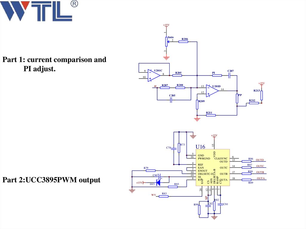
Part 1: current comparison and
PI adjust.
9
U201C
R205
8
C207
PI
10
IF
+15V
R208
R207
13
U201D
14
R213
12
PP
C205
R212
R209
R211
U16
R79
C80
+
D15
R85
20
+15V
REF
EAN
ENOUT
DELSETC-D
SS
RT
WV
OUTC
OUTB
OUTA
R99
C02
6
13
R86
R82
C81
OUTD
14
R87
OUTC
17
R88
OUTB
18
OUTA
R89
R83
SP
Part 2:UCC3895PWM output
CLKSYNC
OUTD
CS
ADS
DELSETA-B
RAMP
CT
4
1
2
10
19
8
GND
PWRGND
EAP
5
16
12
11
9
3
7
C78
VDD
R73
15
+15V
33.
C111R242
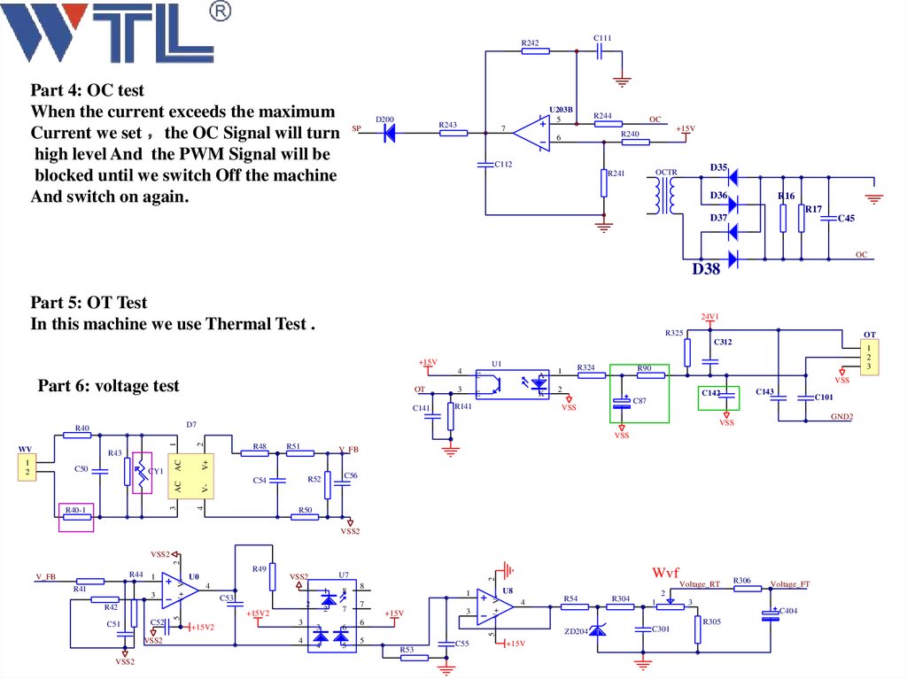
Part 4: OC test
When the current exceeds the maximum
Current we set the OC Signal will turn
high level And the PWM Signal will be
blocked until we switch Off the machine
And switch on again.
D200
U203B
5
R243
SP
R244
7
OC
+15V
R240
6
C112
D35
OCTR
R241
D36
R16
R17
D37
C45
OC
D38
Part 5: OT Test
In this machine we use Thermal Test .
24V1
R325
OT
C312
+15V
U1
4
Part 6: voltage test
OT
C141
3
C
A
E
K
R141
R324
1
R90
VSS
2
C143
C142
C101
C87
VSS
GND2
VSS
D7
R40
1
2
3
2
1
VSS
WV
R48
C50
R40-1
V_FB
V-
C56
R52
C54
4
3
AC
CY1
R51
V+
1
2
AC
R43
R50
VSS2
2
VSS2
3
C53
R42
2
2
+15V2
5
C52
1
+15V2
3
8
7
3
6
4
5
8
Wvf
1
7
+15V
3
Voltage_RT
U8
4
VSS2
VSS2
4
R54
5
R53
C55
R304
R306
Voltage_FT
2
1
3
C404
6
ZD204
5
C51
U7
VSS2
1
4
2
U0
V+ V-
R41
R49
V+ V-
R44 1
V_FB
+15V
C301
R305
34.
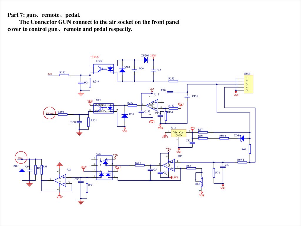
Part 7: gun、remote、pedal.The Connector GUN connect to the air socket on the front panel
cover to control gun、remote and pedal respectly.
ZD201 24V1
VCC
U304
D203
gun
FC6
FC5
R250
GUN
1
2
3
4
5
R253
R249
FC8
2
VSS
U14
3
R150
R252
1
Collector
LED Anode
4
2
Emitter
LED Cathode
R151
C150
IN+
OUT
3
INC152
C153
R153
15V1
R154
5
D20
VSS
C158
1
V+ V-
VCC
4
remote
R70
U15
15V1
U13
VSS
1
VSS
Vin Vout
GND
2
24V1
15V1
3
R67
R66
R66-1
VSS
+15V
C96
3
R45
3
5
4
15V1
3
2
C5
3
C5-1
4
R69-1
C90
R65
1
5
2
6
IN+
OUT
IN-
15V1
R71
1
1
7
4
2
2
R68
3
4
6
R254
2
U12
1
VSS
3
2
+15V
U2
1
V+ V-
R63 R31
V+ V-
C97
8
VSS
1
5
7
5
ZD7
8
R69
VSS
U20
pedal_I
ZD8
C32
VSS
35.
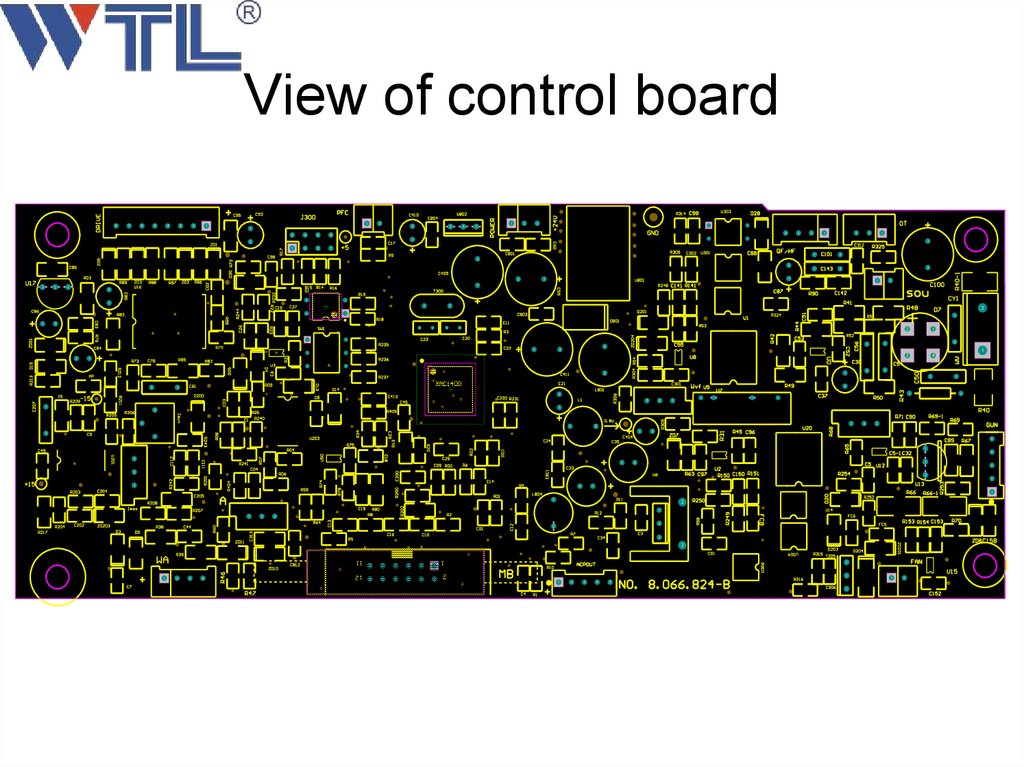
View of control board8
7
6
5
4
3
2
1
1
2
2
1
2
4
6
3
2
1
1
2
3
3
5
4
2
3
4
1
1
1
8
2
3
2
1
3
2
1
1
7
1
2
1
2
2
2
2
3
2
1
2
2
1
1
2
1
1
1
1
3
2
4
1
1
2
2
1
2
1
2
1
1
2
1
2
2
5
3
4
2
4
2
1
2
1
2
1
1
3
2
1
1
2
5
2
7
1
3
2
1
1
2
1
2
3
2
2
1
2
1
1
1
1
1
2
1
2
2
6
2
3
2
1
5
1
3
1
2
2
2
3
1
2
4
3
2
1
1
1
2
1
1
2
3
2
2
3
2
1
2
3
4
11
9
7
5
3
1
12
10
8
6
4
2
3
2
1
2
3
4
5
1
1
2
36.
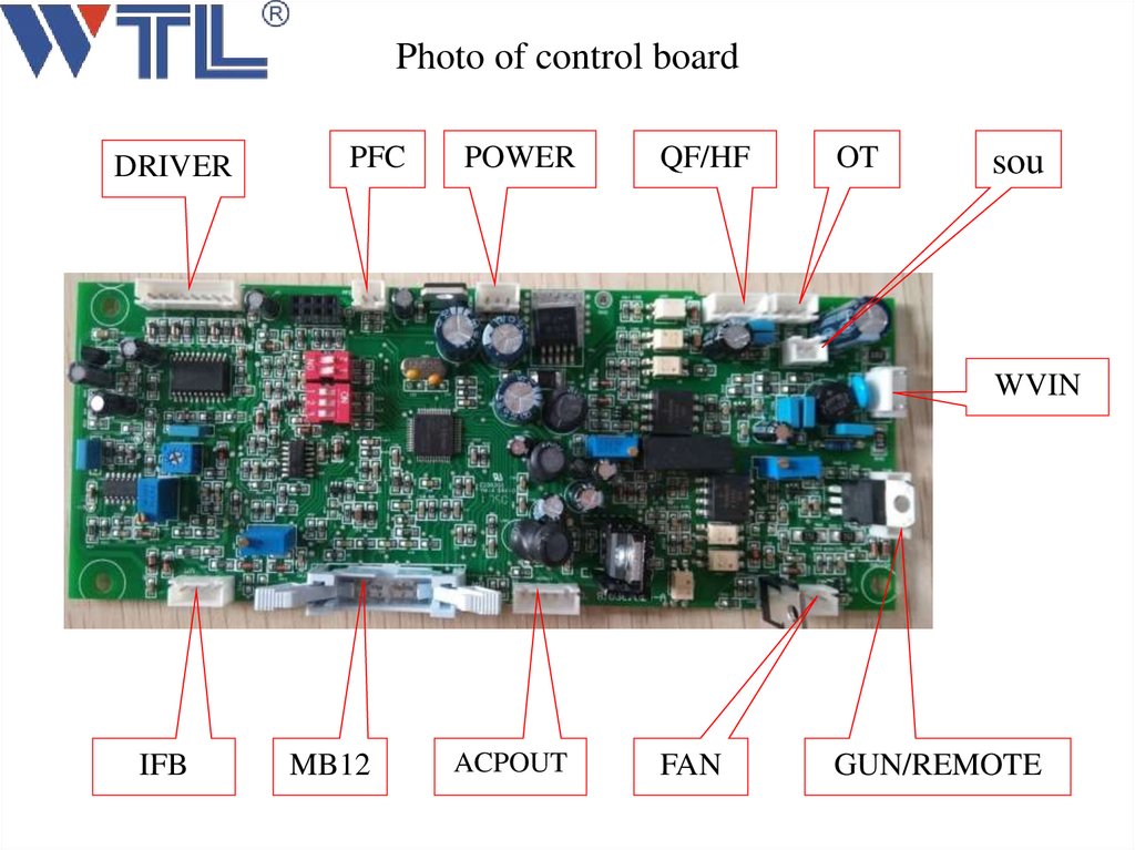
Photo of control boardDRIVER
PFC
POWER
QF/HF
OT
sou
WVIN
IFB
MB12
ACPOUT
FAN
GUN/REMOTE
37.
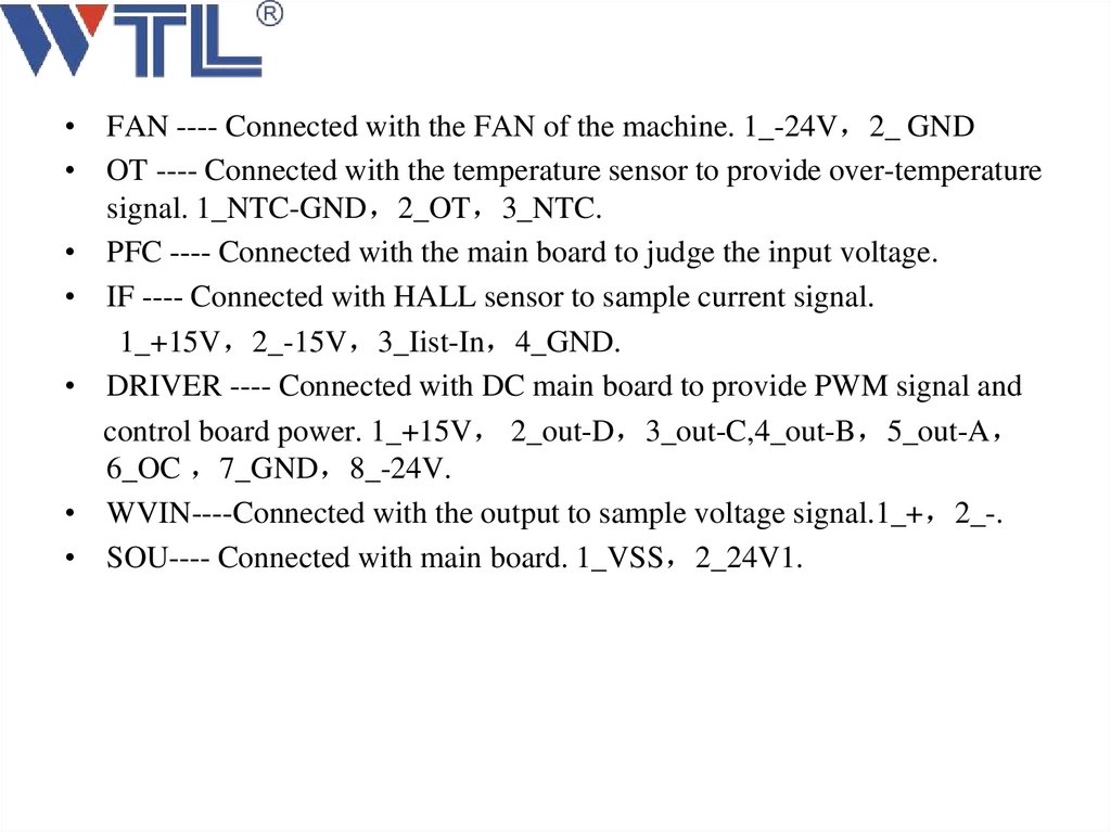
• FAN ---- Connected with the FAN of the machine. 1_-24V 2_ GND• OT ---- Connected with the temperature sensor to provide over-temperature
signal. 1_NTC-GND 2_OT 3_NTC.
• PFC ---- Connected with the main board to judge the input voltage.
• IF ---- Connected with HALL sensor to sample current signal.
1_+15V 2_-15V 3_Iist-In 4_GND.
• DRIVER ---- Connected with DC main board to provide PWM signal and
control board power. 1_+15V 2_out-D 3_out-C,4_out-B 5_out-A
6_OC 7_GND 8_-24V.
• WVIN----Connected with the output to sample voltage signal.1_+ 2_-.
• SOU---- Connected with main board. 1_VSS 2_24V1.
38.
GUN/REMOTE ---- Connected with the gun and remote to provide signal
POWER ---- Connected with main board. 1_+24V 2_GND 3_-24V.
MB12---- Connected with panel board .
QF/HF---- Connected with gas valve and main board to provide signal.
DRIVER ---- Connected with AC main board to provide PWM signal and
control board power. 1_+15V 2_GND 3_AC1,4_AC2.
39.
4、Introduction of panel circuit40.
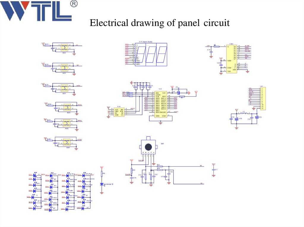
Electrical drawing of panel circuitU15 Ampere display
VCC
R113
3
C31
4
O1 O2
1
2
C1 C2
11
7
4
2
1
10
5
6
3
12
9
8
SEGA
SEGB
SEGC
SEGD
SEGE
SEGF
SEGG
gas
KG1
SEGDP
DIG0
DIG1
DIG2
VCC
R119
3
C40
4
O1 O2
1
HF
A
B
C
D
E
F
G
NC
DP
DIG1
DIG2
DIG3
A/D
U401
R3
3
C39
VCC
16
8
7
X0
X1
X2
X3
X4
X5
X6
X7
13
14
15
12
1
5
2
4
AC/DC
MMA
4T/2T
Encoder
11
10
9
6
A
B
C
gas
pulse
HF
VDD
C430
2
C1 C2
X
GND
A
B
C
INH
VEE
KG2
VCC
R118
3
C41
4
O1 O2
1
pulse
C33
3
DIN R44
CS
R45
SLCK R46
4
O1 O2
C32 1
3
8
6
7
5
C36
4
O1 O2
1
U14
VCC
VCC
DO
ORG SCK
DC
DI
GND
CS
4
2
3
1
1
12
13
2
11
6
7
3
10
5
8
24
DIG0
DIG1
DIG2
DIG3
DIG4
DIG5
DIG6
DIG7
4T/2T
2
C1 C2
KG4
VCC
R115
VCC
J12
C9
CS
DIN
SLCK
DOUT
A/D
B1
A
B0
B
C
U12
KG3
VCC
R114
R47 R48C34 R49 C35
2
C1 C2
DOUT
4
DIN
VCC
LOAD
CLK
ISET
DIG0 SEG A
DIG1 SEG B
DIG2 SEG C
DIG3 SEG D
DIG4 SEG E
DIG5 SEG F
DIG6 SEG G
DIG7
DOUTSEG DP
GND
GND
19
C5
18
14
16
20
23
21
15
17
SEGA
SEGB
SEGC
SEGD
SEGE
SEGF
SEGG
22
SEGDP
VCC
R1
VCC
1
9
C55
MMA
2
C1 C2
KG5
VCC
R116
3
C37 1
4
O1 O2
AC/DC
2
C1 C2
MP1
VCC
A
C
B
E
5
4
3
2
1
D
KG6
Encoder
VCC
R53
VCC
B0
R54
C1
SEGB
SEGC
hot start
SEGD
arc force
SEGE
pre flow
DIG6 SEGA
post_flow
DIG7
initial amps
crater current
MMA
up slope
width
DC
SEGG
SEGD
SEGE
frequency
SEGG
SEGC
base current
SEGF
FAULT 黄
RW
Encoder
C51
C50
C54
C52
C53
SEGB
peak current
AC-frequency
SEGF
SEGG
gas
V
SEGE
SEGF
SEGB
percent
SEGD
SEGE
HF
hertz
SEGC
SEGD
DIG5 SEGA
second
SEGB
SEGC
pulse
R52
DIG4 SEGA
R51
R50
A
SEGA
SEGF
SEGG
down_slope
2T
4T
clearence
AC
POWER 绿
B1
L1
1
C56
2
1
2
3
4
5
6
7
8
9
10
11
12
2
C01
C02
41.
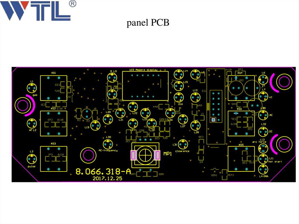
panel PCB12
2
4
2
11
10
9
8
2
7
1
2
1
3
1
1
1
2
2
2
1
1
1
2
1
1
1
3
2
2
4
2
3
4
5
2
1
2
1
11
12
9
10
7
8
5
6
3
4
1
2
2
4
2
1
2
1
2
1
3
1
2
2
2
1
1
2
2
2
1
1
2
3
3
2
1
2
1
2
1
1
1
2
2
2
1
1
2
1
2
1
1
2
2
1
4
2
3
1
4
1
2
4
1
1
2
2
1
1
3
5
1
4
2
2
1
2
1
42.
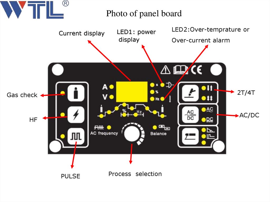
Photo of panel boardCurrent display
LED1: power
display
LED2:Over-temprature or
Over-current alarm
2T/4T
Gas check
AC/DC
HF
PULSE
Process selection
43.
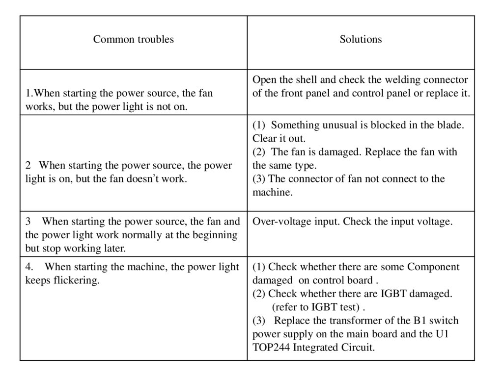
Common troubles1.When starting the power source, the fan
works, but the power light is not on.
2 When starting the power source, the power
light is on, but the fan doesn’t work.
Solutions
Open the shell and check the welding connector
of the front panel and control panel or replace it.
(1) Something unusual is blocked in the blade.
Clear it out.
(2) The fan is damaged. Replace the fan with
the same type.
(3) The connector of fan not connect to the
machine.
3 When starting the power source, the fan and
the power light work normally at the beginning
but stop working later.
Over-voltage input. Check the input voltage.
4. When starting the machine, the power light
keeps flickering.
(1) Check whether there are some Component
damaged on control board .
(2) Check whether there are IGBT damaged.
(refer to IGBT test) .
(3) Replace the transformer of the B1 switch
power supply on the main board and the U1
TOP244 Integrated Circuit.
44.
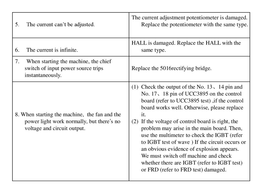
The current can’t be adjusted.The current adjustment potentiometer is damaged.
Replace the potentiometer with the same type.
6.
The current is infinite.
HALL is damaged. Replace the HALL with the
same type.
7.
When starting the machine, the chief
switch of input power source trips
instantaneously.
5.
8. When starting the machine, the fan and the
power light work normally, but there’s no
voltage and circuit output.
Replace the 5016rectifying bridge.
(1) Check the output of the No. 13、14 pin and
No. 17、18 pin of UCC3895 on the control
board (refer to UCC3895 test) ,if the control
board works well. Otherwise, please replace
it.
(2) If the voltage of control board is right, the
problem may arise in the main board. Then,
use the multimeter to check the IGBT (refer
to IGBT test of wave ) If the circuit occurs or
an obvious evidence of explosion appears.
We must switch off machine and check
whether there are IGBT (refer to IGBT test)
or FRD (refer to FRD test) damaged.
45.
5、Troubleshooting46.
A-1:When the machine is turned on , the powerLED is not on.
Resolution:
1.There is no input voltage , check whether there is
input voltage of the connection box on the rear panel;
2.The power LED is damaged or there is a poor
contact , repair the inside circuit of the power LED;
3.There is something wrong with the main board ,
repair it.
A-2:The digital display is not intact.
Resolution:
The nixie tube on the digital display is damaged ,
change it or change the front panel.
47.
A-3:The max/min welding current is not agree with the outfactory set value.Resolution:
1.If the min welding current is not agree with the out-factory set
value , adjust the Imin potentiometer on the control board;
2. If the max welding current is not agree with the out-factory set
value , adjust the Imax potentiometer on the control board.
48.
A-4:The display welding current is not agree with theactual current.
Resolution:
1.The min display welding current is not agree with the
actual current, value , adjust the A potentiometer on the
control board;
2. 1.The max display welding current is not agree with the
actual current, value, adjust the A potentiometer on the
control board.
A-5:The welding current can not be adjusted.
Resolution:
1.The welding current potentiometer on the panel is
damaged or has a poor contact , repair or change it;
2.The control board is damaged , repair or change it.
49.
A-6: the alarm LED is on , maby the following situation1.Over temperature:1)the welding current is too large,
decrease the output welding current;2)using it with too much
time , the fan is damaged, decrease the loading duty. Cycle ,
repair or change the pan.
2. Over voltage : the input power is unstable , insert an
stable or small fluctuation input.
3. Lacking voltage:1) voltage : the input power is unstable ,
insert an stable or small fluctuation input;2)there are too
many electric equipments , decrease the number.
4. over current :there is unusual current in the main circuit ,
check the main circuit and PCB.
50.
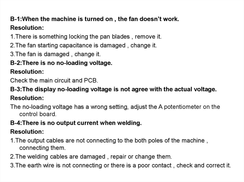
B-1:When the machine is turned on , the fan doesn’t work.Resolution:
1.There is something locking the pan blades , remove it.
2.The fan starting capacitance is damaged , change it.
3.The fan is damaged , change it.
B-2:There is no no-loading voltage.
Resolution:
Check the main circuit and PCB.
B-3:The display no-loading voltage is not agree with the actual voltage.
Resolution:
The no-loading voltage has a wrong setting, adjust the A potentiometer on the
control board.
B-4:There is no output current when welding.
Resolution:
1.The output cables are not connecting to the both poles of the machine ,
connecting them.
2.The welding cables are damaged , repair or change them.
3.The earth wire is not connecting or there is a poor contact , check and correct it.
51.
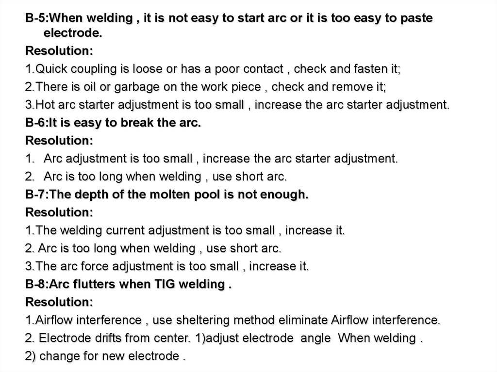
B-5:When welding , it is not easy to start arc or it is too easy to pasteelectrode.
Resolution:
1.Quick coupling is loose or has a poor contact , check and fasten it;
2.There is oil or garbage on the work piece , check and remove it;
3.Hot arc starter adjustment is too small , increase the arc starter adjustment.
B-6:It is easy to break the arc.
Resolution:
1. Arc adjustment is too small , increase the arc starter adjustment.
2. Arc is too long when welding , use short arc.
B-7:The depth of the molten pool is not enough.
Resolution:
1.The welding current adjustment is too small , increase it.
2. Arc is too long when welding , use short arc.
3.The arc force adjustment is too small , increase it.
B-8:Arc flutters when TIG welding .
Resolution:
1.Airflow interference , use sheltering method eliminate Airflow interference.
2. Electrode drifts from center. 1)adjust electrode angle When welding .
2) change for new electrode .
52.
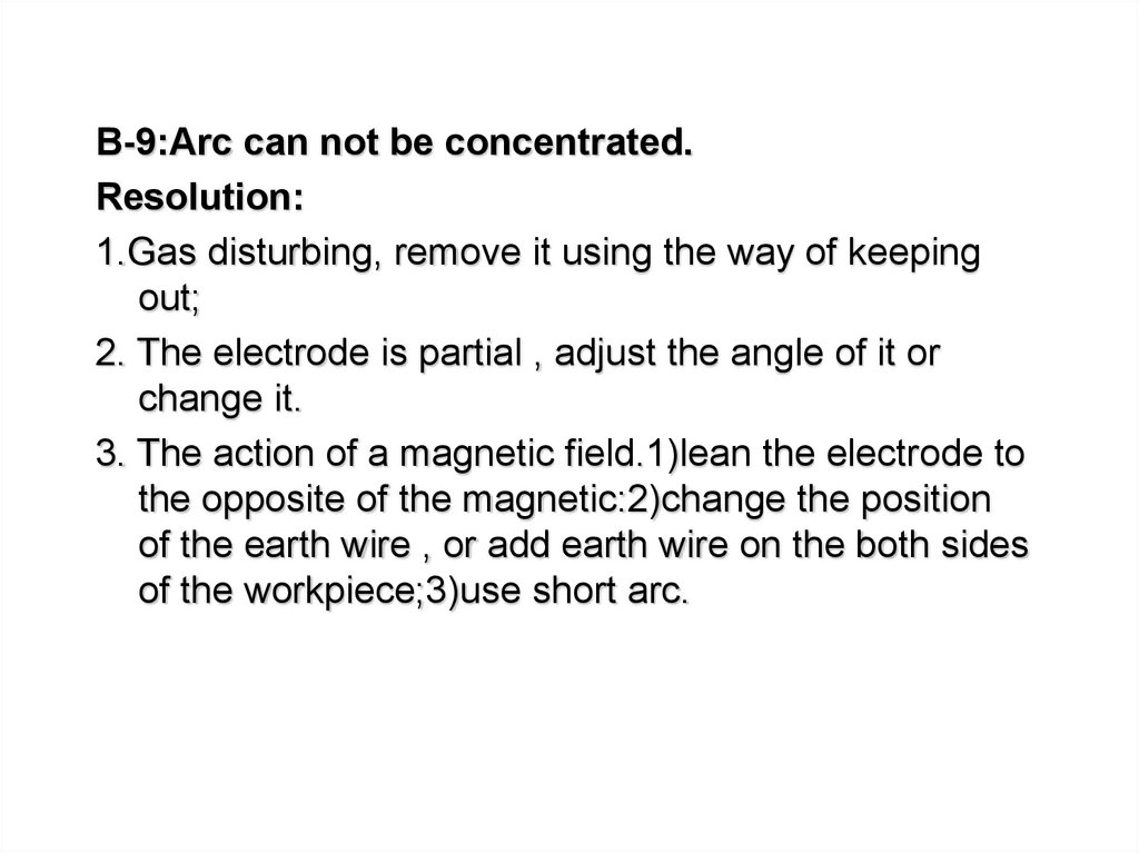
B-9:Arc can not be concentrated.Resolution:
1.Gas disturbing, remove it using the way of keeping
out;
2. The electrode is partial , adjust the angle of it or
change it.
3. The action of a magnetic field.1)lean the electrode to
the opposite of the magnetic:2)change the position
of the earth wire , or add earth wire on the both sides
of the workpiece;3)use short arc.
53.
6.Component test1、 UC3895 Test
2、IGBT Test
3、FRD Test
54.
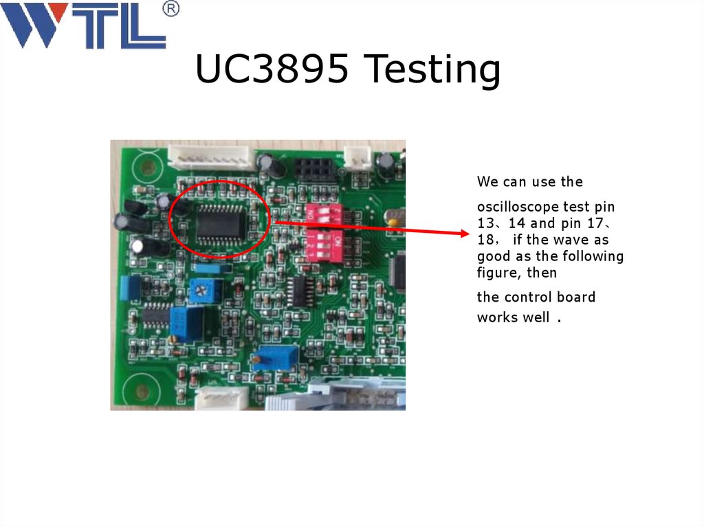
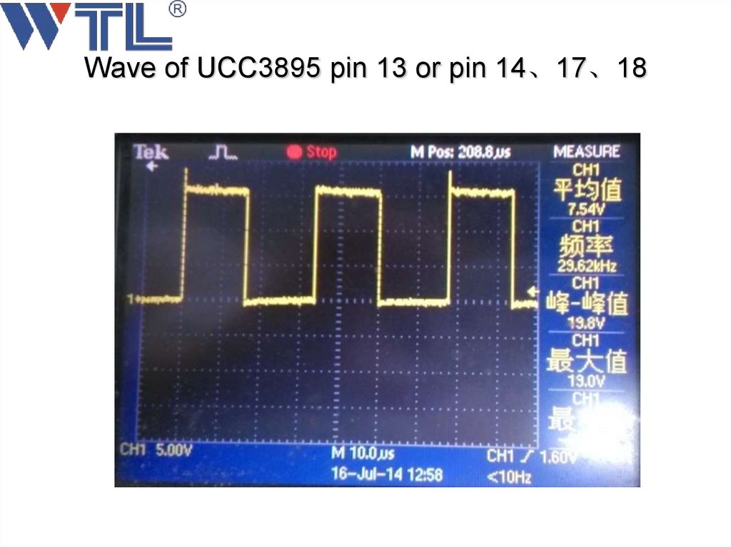
UC3895 TestingWe can use the
oscilloscope test pin
13、14 and pin 17、
18 if the wave as
good as the following
figure, then
the control board
works well .
55.
Wave of UCC3895 pin 13 or pin 14、17、1856.
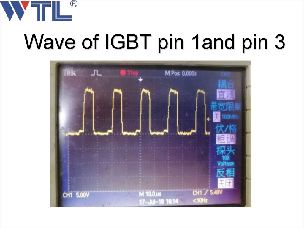
Wave of IGBT pin 1and pin 357.
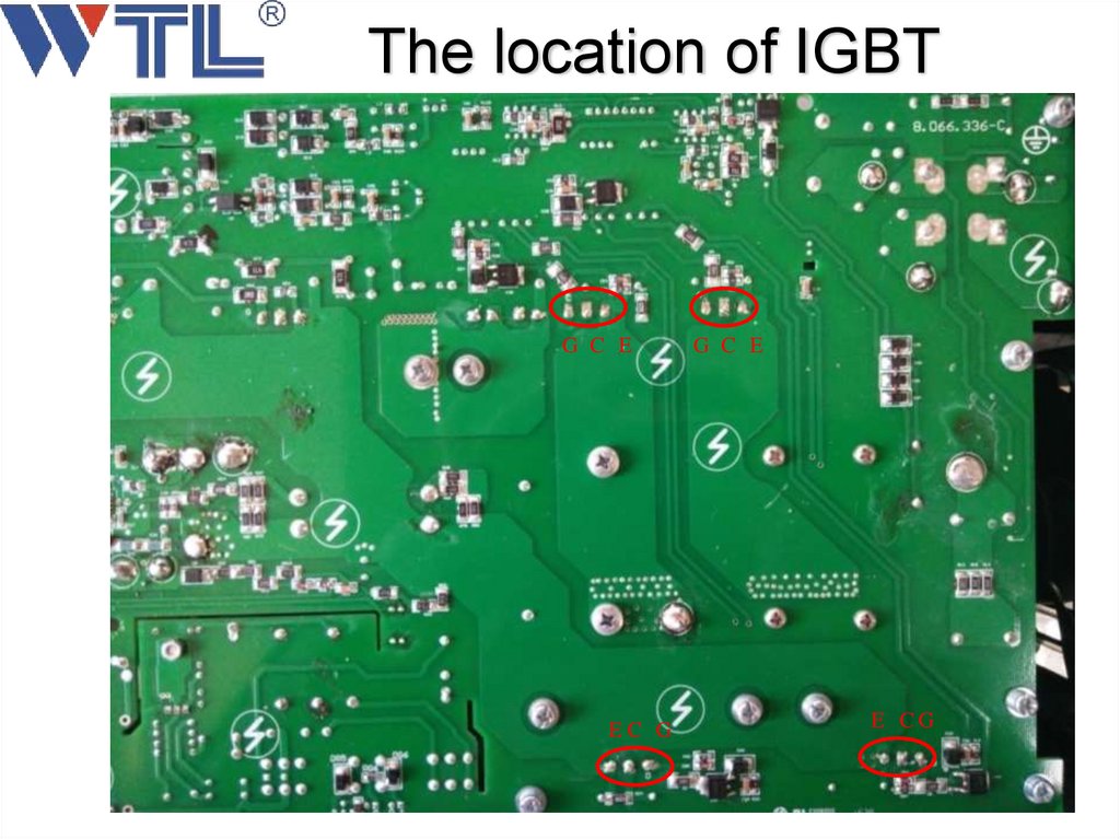
The location of IGBTG C E
EC G
G C E
E CG
58.
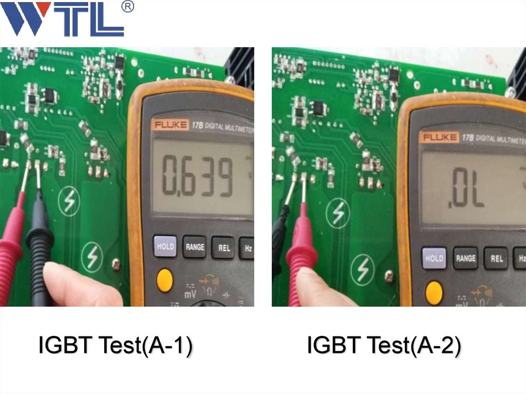
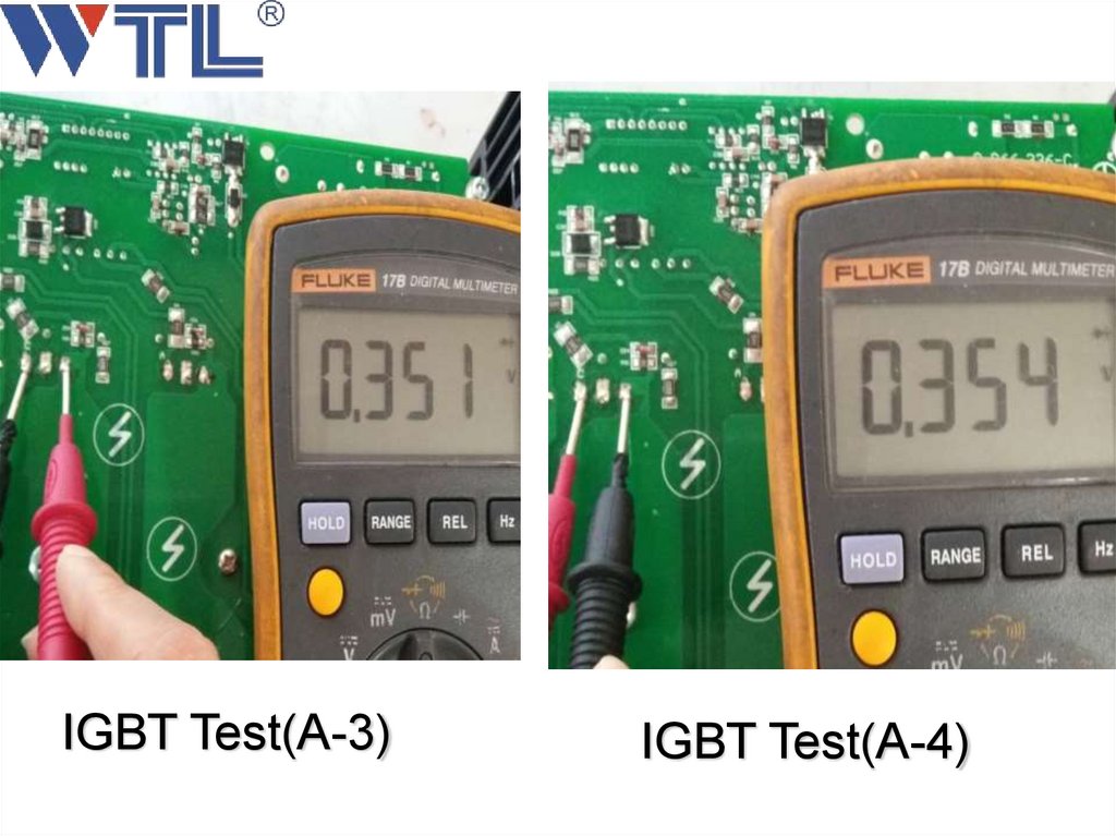
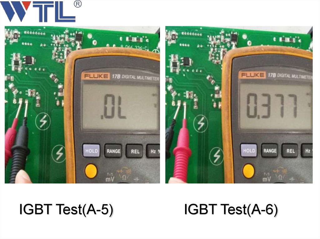
Preparation of test IGBT1、We must Switch off the machine
2、After 5 minutes we can test .
3、Turn the rotary switch to test diode.
4、keep 3 seconds when we test every step.
5、If the result we test as similar as the following
picture .we can say the IGBT is good. Otherwise
there are some IGBT damaged.
59.
IGBT Test(A-1)IGBT Test(A-2)
60.
IGBT Test(A-3)IGBT Test(A-4)
61.
IGBT Test(A-5)IGBT Test(A-6)
62.
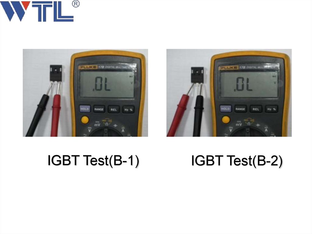
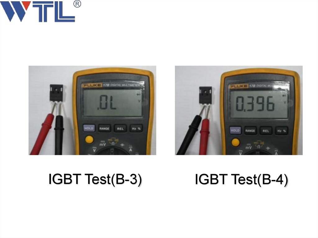
Solutions when the IGBT is damaged.1、 Check the circuit of IGBT driver, may be there
are some components damaged.
2、Remove IGBT one by one and test as following
page.
3、After we Remove the damaged IGBT. Check the
IGBT drive wave (between the G、E) as same as the
below.
4、If not ,we must Replace Components of driver
circuit .
5、Replace IC MIC 4424.
6、 If the wave is ok .Replace the damaged IGBT.
63.
64.
IGBT Test(B-1)IGBT Test(B-2)
65.
IGBT Test(B-3)IGBT Test(B-4)
66.
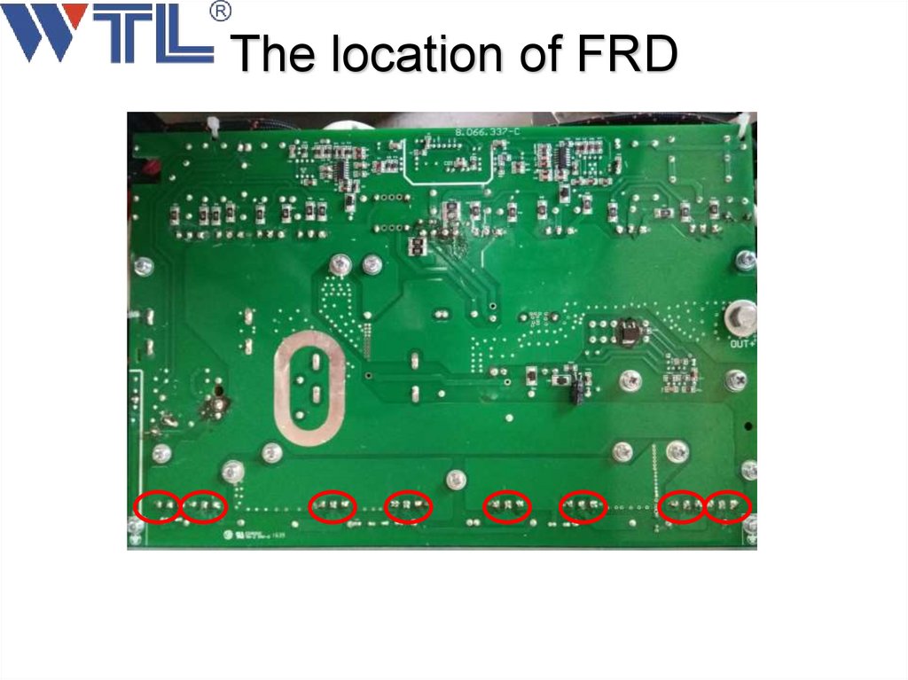
The location of FRD67.
Preparation of test FRD1、We must Switch off the machine
2、After 5 minutes we can test .
3、Turn the rotary switch to test diode.
4、keep 3 seconds when we test every step.
5、If the result we test as similar as the following
picture .we can say the FRD is good. Otherwise
maybe some MUR are damaged.
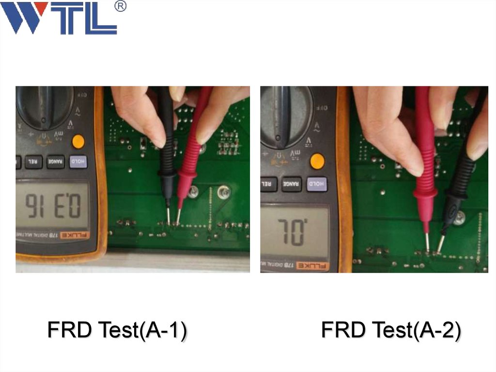
68.
FRD Test(A-1)FRD Test(A-2)
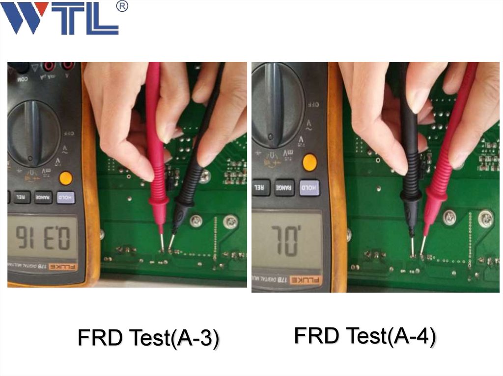
69.
FRD Test(A-3)FRD Test(A-4)
70.
Solutions when the FRD is damaged1、 Remove FRD one by one and test as following
page.
2、 Replace the damaged FRD.
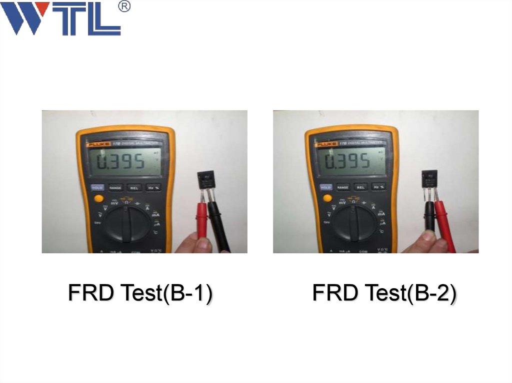
71.
FRD Test(B-1)FRD Test(B-2)
72.
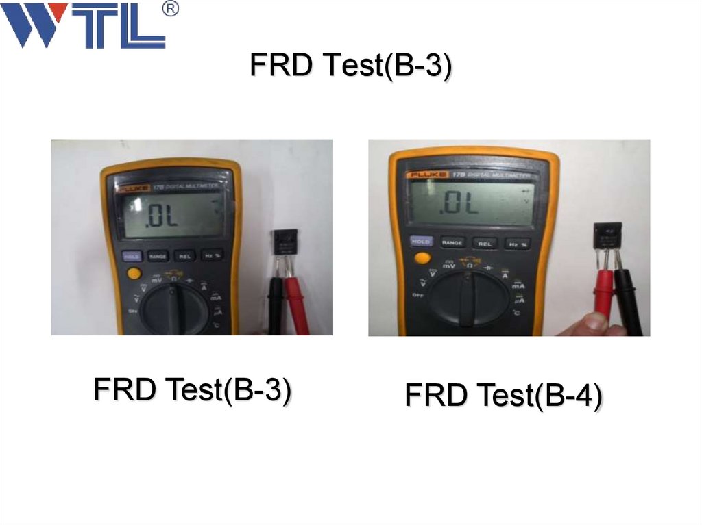
FRD Test(B-3)FRD Test(B-3)
FRD Test(B-4)
73.
Q&A74.
Thanks for yourattention!!!