


 Интернет
Похожие презентации:

")


")

Module 9: The Transport Layer
1.
Module 9: The Transport LayerInstructor Materials
CyberOps Associate v1.0
2.
Module 9: The Transport LayerCyberOps Associate v1.0
3.
Module ObjectivesModule Title: The Transport Layer
Module Objective: Explain how transport layer protocols support network functionality.
Topic Title
Transport Layer Characteristics
Transport Layer Session Establishment
Transport Layer Reliability
Topic Objective
Explain how transport layer protocols support network communication.
Explain how the transport layer establishes communication sessions.
Explain how the transport layer establishes reliable communications.
© 2020 Cisco and/or its affiliates. All rights reserved. Cisco Confidential
9
4.
9.1 Transport LayerCharacteristics
© 2020 Cisco and/or its affiliates. All rights reserved. Cisco Confidential
10
5.
The Transport LayerRole of the Transport Layer
• The transport layer is responsible for logical
communications between applications running on
different hosts.
• As shown in the figure, the transport layer is the
link between the application layer and the lower
layers that are responsible for network
transmission.
• The transport layer has no knowledge of the
destination host type, the type of media for which
the data must travel, the path taken by the data,
the congestion on a link, or the size of the network.
• The transport layer includes two protocols,
Transmission Control Protocol (TCP) and User
Datagram Protocol (UDP).
© 2020 Cisco and/or its affiliates. All rights reserved. Cisco Confidential
11
6.
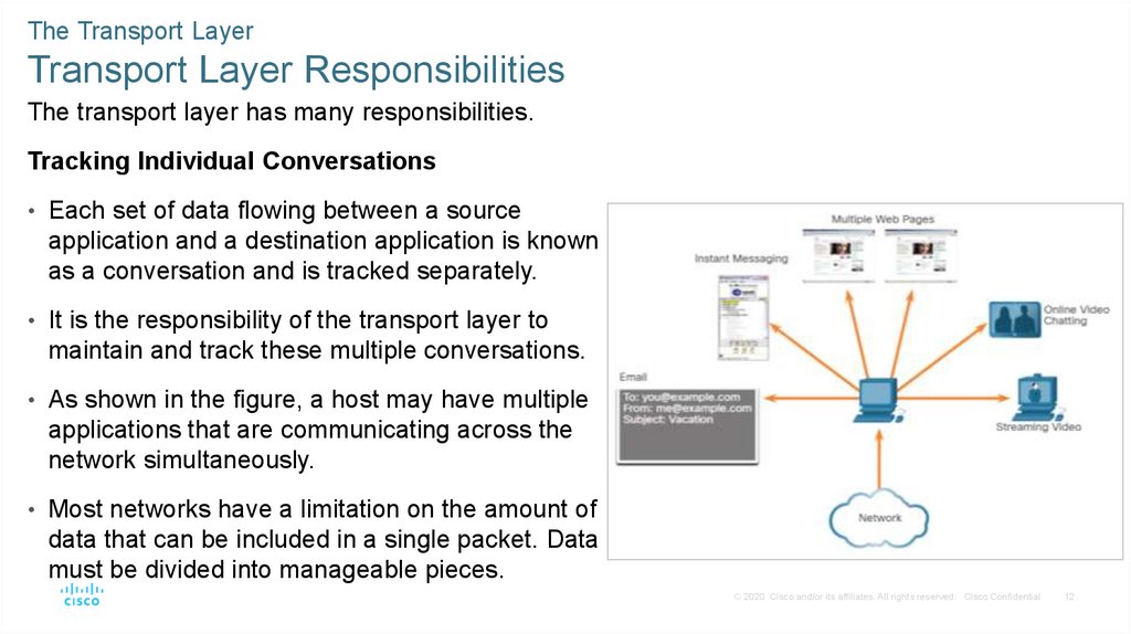
The Transport LayerTransport Layer Responsibilities
The transport layer has many responsibilities.
Tracking Individual Conversations
• Each set of data flowing between a source
application and a destination application is known
as a conversation and is tracked separately.
• It is the responsibility of the transport layer to
maintain and track these multiple conversations.
• As shown in the figure, a host may have multiple
applications that are communicating across the
network simultaneously.
• Most networks have a limitation on the amount of
data that can be included in a single packet. Data
must be divided into manageable pieces.
© 2020 Cisco and/or its affiliates. All rights reserved. Cisco Confidential
12
7.
The Transport LayerTransport Layer Responsibilities (Contd.)
Segmenting Data and Reassembling
Segments
• It is the transport layer responsibility to
divide the application data into
appropriately sized blocks.
• Depending on the transport layer protocol
used, the transport layer blocks are called
either segments or datagrams.
• The figure shows the transport layer using
different blocks for each conversation.
• The transport layer divides the data into
smaller blocks (segments or datagrams)
that are easier to manage and transport.
© 2020 Cisco and/or its affiliates. All rights reserved. Cisco Confidential
13
8.
The Transport LayerTransport Layer Responsibilities (Contd.)
Add Header Information
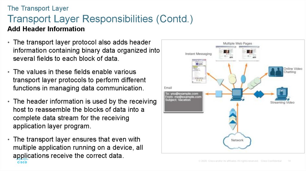
• The transport layer protocol also adds header
information containing binary data organized into
several fields to each block of data.
• The values in these fields enable various
transport layer protocols to perform different
functions in managing data communication.
• The header information is used by the receiving
host to reassemble the blocks of data into a
complete data stream for the receiving
application layer program.
• The transport layer ensures that even with
multiple application running on a device, all
applications receive the correct data.
© 2020 Cisco and/or its affiliates. All rights reserved. Cisco Confidential
14
9.
The Transport LayerTransport Layer Responsibilities (Contd.)
Identifying the Applications
• The transport layer must be able
to separate and manage multiple
communications with different
transport requirement needs.
• To pass data streams to the
proper applications, the transport
layer identifies the target
application using an identifier
called a port number.
• As shown in the figure, each
software process that needs to
access the network is assigned a
port number unique to that host.
© 2020 Cisco and/or its affiliates. All rights reserved. Cisco Confidential
15
10.
The Transport LayerTransport Layer Responsibilities (Contd.)
Conversation Multiplexing
• Sending some types of data across a network,
as one complete communication stream, can
consume all the available bandwidth.
• This prevents other communication
conversations from occurring at the same time
and also make error recovery and
retransmission of damaged data difficult.
• As shown in the figure, the transport layer uses
segmentation and multiplexing to enable
different communication conversations to be
interleaved on the same network.
• Error checking can be performed on the data
in the segment, to determine if the segment
was altered during transmission.
© 2020 Cisco and/or its affiliates. All rights reserved. Cisco Confidential
16
11.
The Transport LayerTransport Layer Protocols
• IP is concerned only with the structure,
addressing, and routing of packets.
• IP does not specify how the delivery or
transportation of the packets takes place.
• Transport layer protocols (TCP and UDP) specify
how to transfer messages between hosts, and
are responsible for managing reliability
requirements of a conversation.
• The transport layer includes the TCP and UDP
protocols.
• Different applications have different transport
reliability requirements. Therefore, TCP/IP
provides two transport layer protocols, as shown
in the figure.
© 2020 Cisco and/or its affiliates. All rights reserved. Cisco Confidential
17
12.
The Transport LayerTransmission Control Protocol (TCP)
• TCP is considered a reliable, full-featured transport layer protocol, which ensures that all of
the data arrives at the destination.
• TCP includes fields which ensure the delivery of the application data. These fields require
additional processing by the sending and receiving hosts.
• TCP transport is analogous to sending packages that are tracked from source to destination.
• TCP provides reliability and flow control using these basic operations:
• Number and track data segments transmitted to a specific host from a specific application
• Acknowledge received data
• Retransmit any unacknowledged data after a certain amount of time
• Sequence data that might arrive in wrong order
• Send data at an efficient rate that is acceptable by the receiver
Note: TCP divides data into segments.
© 2020 Cisco and/or its affiliates. All rights reserved. Cisco Confidential
18
13.
The Transport LayerTransmission Control Protocol (TCP) (Contd.)
In order to maintain the state of a
conversation and track the
information, TCP must first
establish a connection between
the sender and the receiver. This
is why TCP is known as a
connection-oriented protocol.
© 2020 Cisco and/or its affiliates. All rights reserved. Cisco Confidential
19
14.
The Transport LayerTCP Header
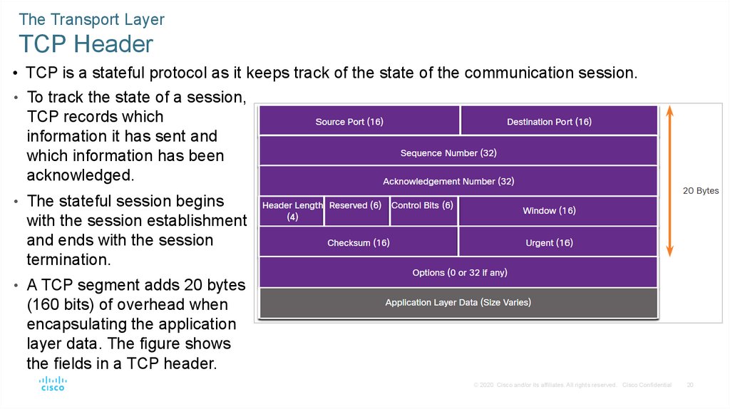
• TCP is a stateful protocol as it keeps track of the state of the communication session.
• To track the state of a session,
TCP records which
information it has sent and
which information has been
acknowledged.
• The stateful session begins
with the session establishment
and ends with the session
termination.
• A TCP segment adds 20 bytes
(160 bits) of overhead when
encapsulating the application
layer data. The figure shows
the fields in a TCP header.
© 2020 Cisco and/or its affiliates. All rights reserved. Cisco Confidential
20
15.
The Transport LayerTCP Header Fields
The table identifies and describes the ten fields in a TCP header.
TCP Header Field
Description
Source Port
A 16-bit field used to identify the source application by port number.
Destination Port
A 16-bit field used to identify the destination application by port number.
Sequence Number
A 32-bit field used for data reassembly purposes.
Acknowledgment
Number
A 32-bit field used to indicate that data has been received and the next byte expected
from the source.
Header Length
A 4-bit field known as ʺdata offsetʺ that indicates the length of the TCP segment header.
Reserved
A 6-bit field that is reserved for future use.
Control bits
A 6-bit field that includes bit codes, or flags, which indicate the purpose and function of
the TCP segment.
Window size
A 16-bit field used to indicate the number of bytes that can be accepted at one time.
Checksum
A 16-bit field used for error checking of the segment header and data.
Urgent
A 16-bit field used to indicate if the contained data is urgent.
© 2020 Cisco and/or its affiliates. All rights reserved. Cisco Confidential
21
16.
The Transport LayerUser Datagram Protocol (UDP)
• UDP is a simpler transport layer protocol than TCP.
• It does not provide reliability and flow control, which means it requires fewer header fields.
• The sender and the receiver UDP processes do not have to manage reliability and flow
control, this means UDP datagrams can be processed faster than TCP segments.
• UDP provides the basic functions for delivering datagrams between the appropriate
applications, with very little overhead and data checking.
• UDP is a connectionless protocol. Because UDP does not provide reliability or flow control,
it does not require an established connection.
• UDP is also known as a stateless protocol. Because UDP does not track information sent or
received between the client and server.
Note: UDP divides data into datagrams that are also referred to as segments.
© 2020 Cisco and/or its affiliates. All rights reserved. Cisco Confidential
22
17.
The Transport LayerUser Datagram Protocol (UDP) (Contd.)
• UDP is also known as a best-
effort delivery protocol
because there is no
acknowledgment that the data
is received at the destination.
• UDP is like placing a regular,
nonregistered, letter in the
mail. The sender of the letter
is not aware of the availability
of the receiver to receive the
letter. Nor is the post office
responsible for tracking the
letter or informing the sender
if the letter does not arrive at
the final destination.
© 2020 Cisco and/or its affiliates. All rights reserved. Cisco Confidential
23
18.
The Transport LayerUDP Header
• UDP is a stateless protocol meaning neither the client, nor the server, tracks the state of the
communication session. If reliability is required when using UDP as the transport protocol, it
must be handled by the application.
• The requirements for delivering live video and voice over the network is the data continues to
flow quickly. Live video and voice applications can tolerate some data loss and are perfectly
suited to UDP.
• The blocks of communication in UDP are called datagrams, or segments. These datagrams are
sent as best effort by the transport layer protocol.
• The UDP header is only has four fields and requires 8 bytes (64 bits). The figure shows the
fields in a UDP header.
© 2020 Cisco and/or its affiliates. All rights reserved. Cisco Confidential
24
19.
The Transport LayerUDP Header Fields
The table identifies and describes the four fields in a UDP header.
UDP Header Field
Description
Source Port
A 16-bit field used to identify the source application by port number.
Destination Port
A 16-bit field used to identify the destination application by port number.
Sequence Number
A 32-bit field used for data reassembly purposes.
Length
A 16-bit field that indicates the length of the UDP datagram header.
Checksum
A 16-bit field used for error checking of the datagram header and data.
© 2020 Cisco and/or its affiliates. All rights reserved. Cisco Confidential
25
20.
The Transport LayerSocket Pairs
• The source and destination ports are placed within the segment. The segments are then
encapsulated within an IP packet.
• The IP packet contains the IP address of the source and destination. The combination of the
source IP address and source port number, or the destination IP address and destination port
number is known as a socket.
• Sockets enable multiple processes, running on a client, to distinguish themselves from each
other, and multiple connections to a server process to be distinguished from each other.
• The source port number acts as a return address for the requesting application.
• The transport layer keeps track of this port and the application that initiated the request so
that when a response is returned, it can be forwarded to the correct application.
© 2020 Cisco and/or its affiliates. All rights reserved. Cisco Confidential
26
21.
The Transport LayerSocket Pairs (Contd.)
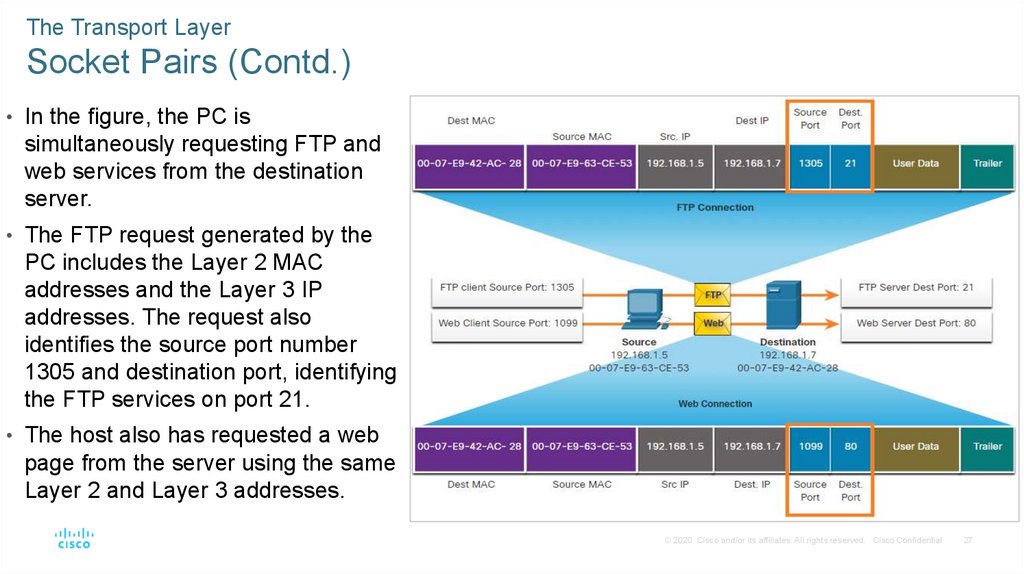
• In the figure, the PC is
simultaneously requesting FTP and
web services from the destination
server.
• The FTP request generated by the
PC includes the Layer 2 MAC
addresses and the Layer 3 IP
addresses. The request also
identifies the source port number
1305 and destination port, identifying
the FTP services on port 21.
• The host also has requested a web
page from the server using the same
Layer 2 and Layer 3 addresses.
© 2020 Cisco and/or its affiliates. All rights reserved. Cisco Confidential
27
22.
The Transport LayerSocket Pairs (Contd.)
• It is using the source port number
1099 and destination port identifying
the web service on port 80.
• The socket is used to identify the
server and service being requested
by the client.
• A client socket with 1099
representing the source port
number might be 192.168.1.5:1099.
The socket on a web server might
be 192.168.1.7:80. Together, these
two sockets combine to form
a socket pair: 192.168.1.5:1099,
192.168.1.7:80
© 2020 Cisco and/or its affiliates. All rights reserved. Cisco Confidential
28
23.
9.2 Transport Layer SessionEstablishment
© 2020 Cisco and/or its affiliates. All rights reserved. Cisco Confidential
29
24.
Transport Layer Session EstablishmentTCP Server Processes
• Each application process running on a server is configured to use a port number. The port
number is either automatically assigned or configured manually by a system administrator.
• An individual server cannot have two services assigned to the same port number within the
same transport layer services.
• A host running a web server application and a file transfer application cannot have both
configured to use the same port, such as TCP port 80.
• An active server application assigned to a specific port is considered open, which means that
the transport layer accepts, and processes segments addressed to that port.
• Any incoming client request addressed to the correct socket is accepted, and the data is
passed to the server application.
• There can be many ports open simultaneously on a server, one for each active server
application.
© 2020 Cisco and/or its affiliates. All rights reserved. Cisco Confidential
30
25.
Transport Layer Session EstablishmentTCP Server Processes (Contd.)
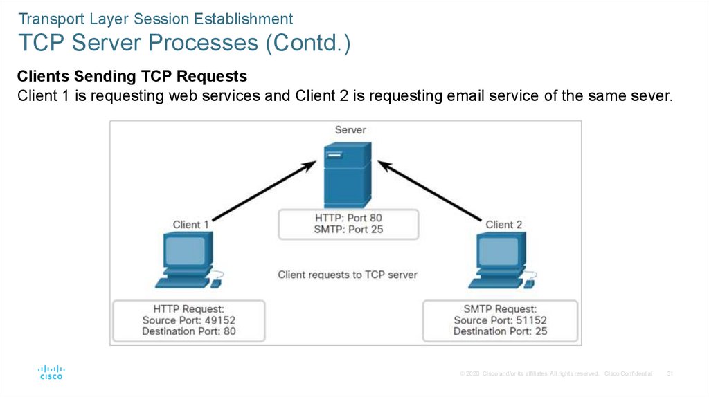
Clients Sending TCP Requests
Client 1 is requesting web services and Client 2 is requesting email service of the same sever.
© 2020 Cisco and/or its affiliates. All rights reserved. Cisco Confidential
31
26.
Transport Layer Session EstablishmentTCP Server Processes (Contd.)
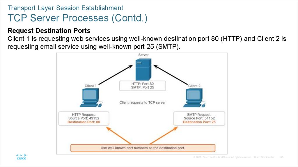
Request Destination Ports
Client 1 is requesting web services using well-known destination port 80 (HTTP) and Client 2 is
requesting email service using well-known port 25 (SMTP).
© 2020 Cisco and/or its affiliates. All rights reserved. Cisco Confidential
32
27.
Transport Layer Session EstablishmentTCP Server Processes (Contd.)
Request Source Ports
Client requests dynamically generate a source port number. In this case, Client 1 is using
source port 49152 and Client 2 is using source port 51152.
© 2020 Cisco and/or its affiliates. All rights reserved. Cisco Confidential
33
28.
Transport Layer Session EstablishmentTCP Server Processes (Contd.)
Response Destination Ports
When the server responds to the client requests, it reverses the destination and source ports of
the initial request. Notice that the Server response to the web request now has destination port
49152 and the email response now has destination port 51152.
© 2020 Cisco and/or its affiliates. All rights reserved. Cisco Confidential
34
29.
Transport Layer Session EstablishmentTCP Server Processes (Contd.)
Response Source Ports
The source port in the server response is the original destination port in the initial requests.
© 2020 Cisco and/or its affiliates. All rights reserved. Cisco Confidential
35
30.
Transport Layer Session EstablishmentTCP Connection Establishment
• In TCP connections, the host client
establishes the connection with the server
using the three-way handshake process.
• The three-way handshake validates that the
destination host is available to
communicate.
• The TCP connection establishment steps
are:
• Step 1. SYN: The initiating client requests
a client-to-server communication session
with the server.
© 2020 Cisco and/or its affiliates. All rights reserved. Cisco Confidential
36
31.
Transport Layer Session EstablishmentTCP Connection Establishment (Contd.)
Step 2. ACK and SYN: The server
acknowledges the client-to-server
communication session and requests a
server-to-client communication session.
Step 3. ACK: The initiating client acknowledges
the server-to-client communication session.
© 2020 Cisco and/or its affiliates. All rights reserved. Cisco Confidential
37
32.
Transport Layer Session EstablishmentSession Termination
• To close a connection, the Finish (FIN) control flag must be set in the segment header.
• To end each one-way TCP session, a two-way handshake, consisting of a FIN segment and
an Acknowledgment (ACK) segment, is used.
• Therefore, to terminate a single conversation supported by TCP, four exchanges are needed
to end both sessions. Either the client or the server can initiate the termination.
• The terms client and server are used as a reference for simplicity, but any two hosts that
have an open session can initiate the termination process.
• When all segments have been acknowledged, the session is closed.
© 2020 Cisco and/or its affiliates. All rights reserved. Cisco Confidential
38
33.
Transport Layer Session EstablishmentSession Termination (Contd.)
The session termination steps are:
Step 1. FIN: When the client has no more
data to send in the stream, it sends a
segment with the FIN flag set.
Step 2. ACK: The server sends an ACK to
acknowledge the receipt of the FIN to terminate
the session from client to server.
© 2020 Cisco and/or its affiliates. All rights reserved. Cisco Confidential
39
34.
Transport Layer Session EstablishmentSession Termination (Contd.)
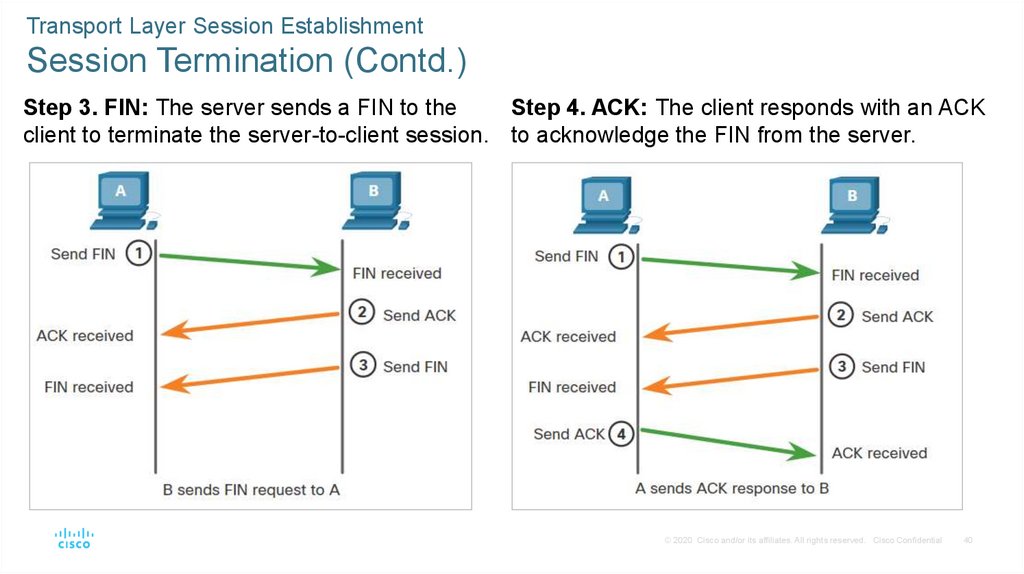
Step 3. FIN: The server sends a FIN to the
Step 4. ACK: The client responds with an ACK
client to terminate the server-to-client session. to acknowledge the FIN from the server.
© 2020 Cisco and/or its affiliates. All rights reserved. Cisco Confidential
40
35.
Transport Layer Session EstablishmentTCP Three-way Handshake Analysis
• Hosts maintain state, track each data segment within a session, and exchange information
about the data is received using the information in the TCP header.
• TCP is a full-duplex protocol, where each connection represents two one-way communication
sessions. To establish the connection, the hosts perform a three-way handshake. As shown
in the figure, control bits in the TCP header indicate the progress and status of the
connection.
• The functions of the three-way handshake are:
• It establishes that the destination device is present on the network.
• It verifies that the destination device has an active service and is accepting requests on the
destination port number that the initiating client intends to use.
• It informs the destination device that the source client intends to establish a communication
session on that port number.
• After the communication is completed the sessions are closed, and the connection is
terminated. The connection and session mechanisms enable TCP reliability function.
© 2020 Cisco and/or its affiliates. All rights reserved. Cisco Confidential
41
36.
Transport Layer Session EstablishmentTCP Three-way Handshake Analysis (Contd.)
The six bits in the Control Bits field of the TCP segment header are also known as flags. A flag is
a bit that is set to either on or off. The six control bits flags are as follows:
• URG - Urgent pointer field
significant
ACK - Acknowledgment flag
used in connection
establishment and session
termination
PSH - Push function
RST - Reset the connection
when an error or timeout occurs
SYN - Synchronize sequence
numbers used in connection
establishment
FIN - No more data from sender
and used in session termination
© 2020 Cisco and/or its affiliates. All rights reserved. Cisco Confidential
42
37.
Transport Layer Session EstablishmentVideo – TCP 3-Way Handshake
Watch the video to learn more of the TCP 3-way handshake.
© 2020 Cisco and/or its affiliates. All rights reserved. Cisco Confidential
43
38.
Transport Layer Session EstablishmentLab – Using Wireshark to Observe the TCP 3-Way Handshake
In this lab, you will complete the following objectives:
• Part 1: Prepare the Hosts to Capture the Traffic
• Part 2: Analyze the Packets using Wireshark
• Part 3: View the Packets using tcpdump
© 2020 Cisco and/or its affiliates. All rights reserved. Cisco Confidential
44
39.
9.3 Transport Layer Reliability© 2020 Cisco and/or its affiliates. All rights reserved. Cisco Confidential
45
40.
Transport Layer ReliabilityTCP Reliability - Guaranteed and Ordered Delivery
There may be times when either TCP segments do not arrive at their destination or arrive
out of order.
For the original message to be understood by the recipient, all the data must be received
and the data in these segments must be reassembled into the original order.
Sequence numbers are assigned in the header for each packet to achieve this goal. The
sequence number represents the first data byte of the TCP segment.
During session setup, an initial sequence number (ISN) is set, which represents the starting
value of the bytes that are transmitted to the receiving application.
As data is transmitted during the session, the sequence number is incremented by the
number of bytes that have been transmitted.
This data byte tracking enables each segment to be uniquely identified and acknowledged.
Missing segments can then be identified.
The ISN is effectively a random number which prevents certain types of malicious attacks.
© 2020 Cisco and/or its affiliates. All rights reserved. Cisco Confidential
46
41.
Transport Layer ReliabilityTCP Reliability - Guaranteed and Ordered Delivery (Contd.)
• Segment sequence numbers indicate
how to reassemble and reorder received
segments, as shown in the figure.
• The receiving TCP process places the
data from a segment into a receiving
buffer.
• Segments are then placed in the proper
sequence order and passed to the
application layer when reassembled.
• Any segments that arrive with sequence
numbers that are out of order are held for
later processing.
• Then, when the segments with the
missing bytes arrives, these segments
are processed in order.
© 2020 Cisco and/or its affiliates. All rights reserved. Cisco Confidential
47
42.
Transport Layer ReliabilityVideo - TCP Reliability – Sequence Numbers and
Acknowledgements
• One of the functions of TCP is to ensure that each segment reaches its destination. The TCP
services on the destination host acknowledge the data that have been received by the source
application.
• Click Play in the figure to view a lesson on TCP sequence numbers and acknowledgments.
© 2020 Cisco and/or its affiliates. All rights reserved. Cisco Confidential
48
43.
Transport Layer ReliabilityTCP Reliability - Data Loss and Retransmission
• TCP provides methods of managing the segment losses by retransmitting the segments for
unacknowledged data.
• The sequence (SEQ) number and acknowledgement (ACK) number are used together to
confirm receipt of the bytes of data contained in the transmitted segments.
• The SEQ number identifies the first byte of data in the segment being transmitted.
• TCP uses the ACK number sent back to the source to indicate the next byte that the receiver
expects to receive. This is called expectational acknowledgement.
• Prior to later enhancements, TCP could only acknowledge the next byte expected.
© 2020 Cisco and/or its affiliates. All rights reserved. Cisco Confidential
49
44.
Transport Layer ReliabilityTCP Reliability - Data Loss and Retransmission (Contd.)
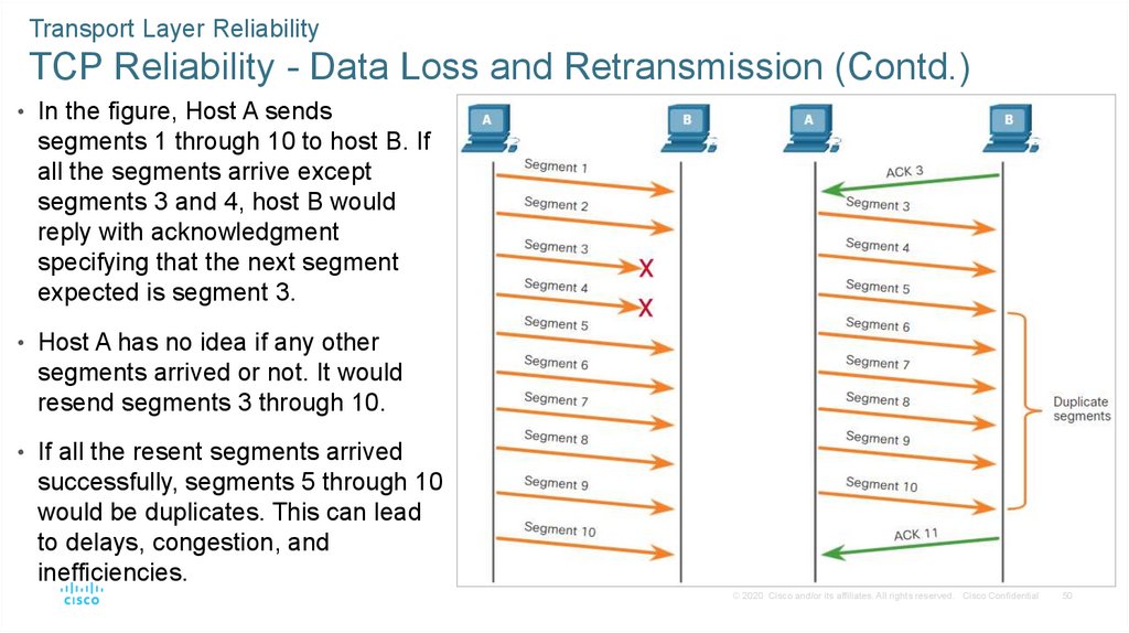
• In the figure, Host A sends
segments 1 through 10 to host B. If
all the segments arrive except
segments 3 and 4, host B would
reply with acknowledgment
specifying that the next segment
expected is segment 3.
• Host A has no idea if any other
segments arrived or not. It would
resend segments 3 through 10.
• If all the resent segments arrived
successfully, segments 5 through 10
would be duplicates. This can lead
to delays, congestion, and
inefficiencies.
© 2020 Cisco and/or its affiliates. All rights reserved. Cisco Confidential
50
45.
Transport Layer ReliabilityTCP Reliability - Data Loss and Retransmission (Contd.)
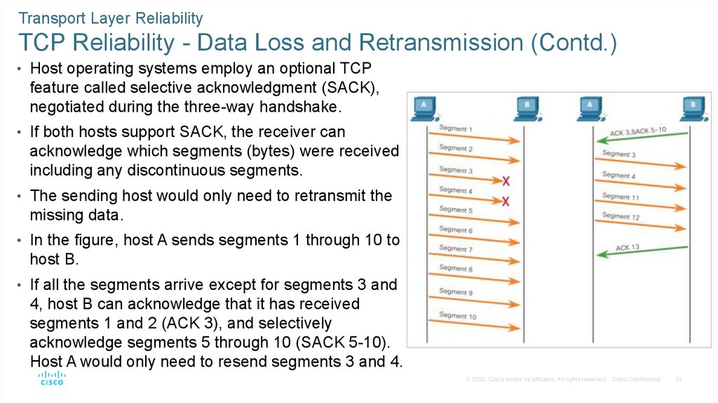
• Host operating systems employ an optional TCP
feature called selective acknowledgment (SACK),
negotiated during the three-way handshake.
• If both hosts support SACK, the receiver can
acknowledge which segments (bytes) were received
including any discontinuous segments.
• The sending host would only need to retransmit the
missing data.
• In the figure, host A sends segments 1 through 10 to
host B.
• If all the segments arrive except for segments 3 and
4, host B can acknowledge that it has received
segments 1 and 2 (ACK 3), and selectively
acknowledge segments 5 through 10 (SACK 5-10).
Host A would only need to resend segments 3 and 4.
© 2020 Cisco and/or its affiliates. All rights reserved. Cisco Confidential
51
46.
Transport Layer ReliabilityVideo - TCP Reliability - Data Loss and Retransmission
Click Play in the figure to view a lesson on TCP retransmission.
© 2020 Cisco and/or its affiliates. All rights reserved. Cisco Confidential
52
47.
Transport Layer ReliabilityTCP Flow Control - Window Size and Acknowledgments
• TCP also provides mechanisms for flow control. Flow control is the amount of data that the
destination can receive and process reliably.
• Flow control helps maintain the reliability of TCP transmission by adjusting the rate of data
flow between source and destination for a given session.
• To accomplish this, the TCP header includes a 16-bit field called the window size.
• The window size that determines the number of bytes that can be sent before expecting an
acknowledgment.
• The acknowledgment number is the number of the next expected byte.
• The window size is the number of bytes that the destination device of a TCP session can
accept and process at one time.
© 2020 Cisco and/or its affiliates. All rights reserved. Cisco Confidential
53
48.
Transport Layer ReliabilityTCP Flow Control - Window Size and Acknowledgments (Contd.)
• The figure shows an example of window
size and acknowledgments.
• The window size is included in every TCP
segment so the destination can modify the
window size at any time depending on
buffer availability.
• The initial window size is agreed upon
when the TCP session is established
during the three-way handshake.
• The source device must limit the number
of bytes sent to the destination device
based on the window size of the
destination. Only after the source receives
an acknowledgment, it can continue
sending more data for the session.
© 2020 Cisco and/or its affiliates. All rights reserved. Cisco Confidential
54
49.
Transport Layer ReliabilityTCP Flow Control - Window Size and Acknowledgments (Contd.)
• The destination will not wait for all the bytes for its window size to be received before replying
with an acknowledgment.
• As the bytes are received and processed, the destination will send acknowledgments to
inform the source that it can continue to send additional bytes.
• A destination sending acknowledgments as it processes bytes received, and the continual
adjustment of the source send window, is known as sliding windows.
• If the availability of the destination’s buffer space decreases, it may reduce its window size to
inform the source to reduce the number of bytes it should send without receiving an
acknowledgment.
Note: Devices today use the sliding windows protocol. The receiver sends an acknowledgment
after every two segments it receives. The advantage of sliding windows is that it allows the
sender to continuously transmit segments, as long as the receiver is acknowledging previous
segments.
© 2020 Cisco and/or its affiliates. All rights reserved. Cisco Confidential
55
50.
Transport Layer ReliabilityTCP Flow Control - Maximum Segment Size (MSS)
• In the figure, the source is
transmitting 1,460 bytes of data
within each TCP segment. This is the
Maximum Segment Size (MSS) that
the destination device can receive.
• The MSS is part of the options field
in the TCP header that specifies the
largest amount of data, in bytes, that
a device can receive in a single TCP
segment.
• The MSS size does not include the
TCP header.
• The MSS is included during the
three-way handshake.
© 2020 Cisco and/or its affiliates. All rights reserved. Cisco Confidential
56
51.
Transport Layer ReliabilityTCP Flow Control - Maximum Segment Size (MSS) (Contd.)
• A common MSS is 1,460 bytes when using IPv4. A host determines the value of its MSS field
by subtracting the IP and TCP headers from the Ethernet maximum transmission unit (MTU).
• On an Ethernet interface, the default MTU is 1500 bytes. Subtracting the IPv4 header of 20
bytes and the TCP header of 20 bytes, the default MSS size will be 1460 bytes, as shown in
the figure.
© 2020 Cisco and/or its affiliates. All rights reserved. Cisco Confidential
57
52.
Transport Layer ReliabilityTCP Flow Control - Congestion Avoidance
• When congestion occurs on a network, it results in packets being discarded by the
overloaded router.
• When packets containing TCP segments do not reach their destination, they are left
unacknowledged.
• By determining the rate at which TCP segments are sent but not acknowledged, the source
can assume a certain level of network congestion.
• Whenever there is congestion, retransmission of lost TCP segments from the source will
occur.
• If the retransmission is not properly controlled, the additional retransmission of the TCP
segments can make the congestion even worse.
• Not only are new packets with TCP segments introduced into the network, but the feedback
effect of the retransmitted TCP segments that were lost will also add to the congestion.
• To avoid and control congestion, TCP employs several congestion handling mechanisms,
timers, and algorithms.
© 2020 Cisco and/or its affiliates. All rights reserved. Cisco Confidential
58
53.
Transport Layer ReliabilityTCP Flow Control - Congestion Avoidance (Contd.)
• If the source determines that the TCP
segments are either not being
acknowledged or not acknowledged in a
timely manner, then it can reduce the
number of bytes it sends before receiving
an acknowledgment.
• As shown in the figure, PC A senses
there is congestion and therefore,
reduces the number of bytes it sends
before receiving an acknowledgment from
PC B.
• Acknowledgment numbers are for the
next expected byte and not for a
segment. The segment numbers used are
simplified for illustration purposes.
© 2020 Cisco and/or its affiliates. All rights reserved. Cisco Confidential
59
54.
Transport Layer ReliabilityLab – Exploring Nmap
• Port scanning is usually part of a reconnaissance attack.
• There are a variety of port scanning methods that can be used.
• We will explore how to use the Nmap utility. Nmap is a powerful network utility that
is used for network discovery and security auditing.
© 2020 Cisco and/or its affiliates. All rights reserved. Cisco Confidential
60
55.
9.4 The Transport LayerSummary
© 2020 Cisco and/or its affiliates. All rights reserved. Cisco Confidential
61
56.
The Transport Layer SummaryWhat Did I Learn in this Module?
• The transport layer is the link between the application layer and the lower layers of the OSI
model that are responsible for network transmission.
• The transport layer includes TCP and UDP. Transport layer protocols specify how to transfer
messages between hosts and is responsible for managing reliability requirements of a
conversation.
• The transport layer is responsible for tracking conversations (sessions), segmenting data and
reassembling segments, adding segment header information, identifying applications, and
conversation multiplexing.
• TCP is stateful and reliable. It acknowledges data, resends lost data, and delivers data in
sequenced order. TCP is used for email and the web.
• UDP is stateless and fast. It has low overhead, does not requires acknowledgments, does
not resend lost data, and processes data in the order in which it arrives. UDP is used for VoIP
and DNS.
© 2020 Cisco and/or its affiliates. All rights reserved. Cisco Confidential
62
57.
The Transport Layer SummaryWhat Did I Learn in this Module? (Contd.)
• The TCP and UDP transport layer protocols use port numbers to manage multiple
simultaneous conversations. This is why the TCP and UDP header fields identify a source
and destination application port number.
• The three-way handshake establishes that the destination device is present on the network. It
verifies that the destination device has an active service that is accepting requests on the
destination port number that the initiating client intends to use.
• The six control bits flags are: URG, ACK, PSH, RST, SYN, and FIN and are used to identify
the function of TCP messages that are sent.
• For the original message to be understood by the recipient, all the data must be received and
the data in these segments must be reassembled into the original order.
• Host operating systems today typically employ an optional TCP feature called selective
acknowledgment (SACK), which is negotiated during the three-way handshake.
• Flow control helps maintain the reliability of TCP transmission by adjusting the rate of data
flow between source and destination.
© 2020 Cisco and/or its affiliates. All rights reserved. Cisco Confidential
63