


 Информатика
Похожие презентации:


")


")

Compass-3d
1.
2.
• COMPASS is a product of the Russiancompany "ASKON".This is a
computer-aided design system with
the possibility of documentation in
accordance with the standards of the
ESKD series. The drawing and graphic
editor (COMPASS-Graph) is designed
to automate design work in various
industries. It can be successfully used
in mechanical engineering,
architecture, construction, drawing
up plans and diagrams - wherever it
is necessary to develop and produce
drawing and text documentation.
3.
• This CAD comes in severalversions:
• Compass-3D,
• Compass CHART,
• Compass-SPDS,
• Compass-3D LTCompass-3D
Home
• That are designed for threedimensional design and/or flat
drawing.
4.
• Compass-3D LT and Compass-3D Home areintended for non-commercial use.COMPASSGRAPH is used as an integrated 3D COMPASS
module with sketches and drawings, or as a
separate product that completely solves the
problems of two-dimensional design and the
release of the necessary documentation.
• The graph is able to automatically generate
associative views of 3-dimensional models
(sections, sections, local sections and views,
views with a gap and arrow). All of them are
associated with the model: changing the
model leads to the transformation of the
image in the drawing.
• Using the COMPASS system, you can create
three-dimensional associative models of
parts and individual units that contain
original or standardized components.
5.
• In the COMPASS CAD, various calculationsand analysis of products are performed by
the following modules: cablesand harnesses
3D - an addition that allows you to
automate the process of 3-dimensional
modeling of electrical harnesses and cables,
as well as to produce design documentation
for these products;
• Pipelines is a 3D module designed to
automate pipeline development work. This
library is used for the design of engineering
networks and in the field of mechanical
engineering;
• Spring is a module that provides calculation
(design or verification) of poppet springs,
cylindrical helical springs and torsion
springs.
6.
Program Features• Own core. The program is built on its own, unique core
that supports the application functions as much as
possible;
• Russian-language interface. The application is completely
in Russian and has a fairly simple and intuitive interface,
which will not be difficult to understand;
• Integration with other programs. Everything created in
Compass can be transferred to other CAD systems and
work with the source data without any problems.;
• Support for various file formats. You will have no
problems with exporting or importing the created
products: the program supports the most popular file
formats;
• Possibility of designing pipelines, cables and cable
systems. Thanks to CAD, most of the work can be done
automatically, without significant effort. This feature
greatly simplifies the design at various enterprises;Builtin module for creating electrical circuits.
7.
Commercial versions• Compass-3DThe Compass-3D system is
designed to create three-dimensional
associative models of individual parts and
assembly units containing both original and
standardized structural elements. Parametric
technology allows you to quickly obtain models
of standard products based on a previously
designed prototype. Numerous service
functions facilitate the solution of auxiliary
tasks of design and maintenance of
production.
• The Compass-3D system includes the following
components: a three-dimensional solid-state
modeling system, a universal computer-aided
design system "Compass-Graph" and a module
for generating specifications. The key feature
of Compass-3D is the use of its own
mathematical core and parametric
technologies.
8.
• The Compass-Graph system ispart of Compass-3D and is
designed to automate design
work in various industries
(mechanical engineering,
architecture, construction)
when creating drawings of
individual parts and assembly
units containing both original
and standardized structural
elements, diagrams,
specifications, tables,
instructions, design and
explanatory notes, technical
specifications, text and other
documents.
9.
Compass Builder• The Compass-Builder system is designed to automate design work in
the construction industry. It allows you to create working
documentation according to the SPDS standards.
10.
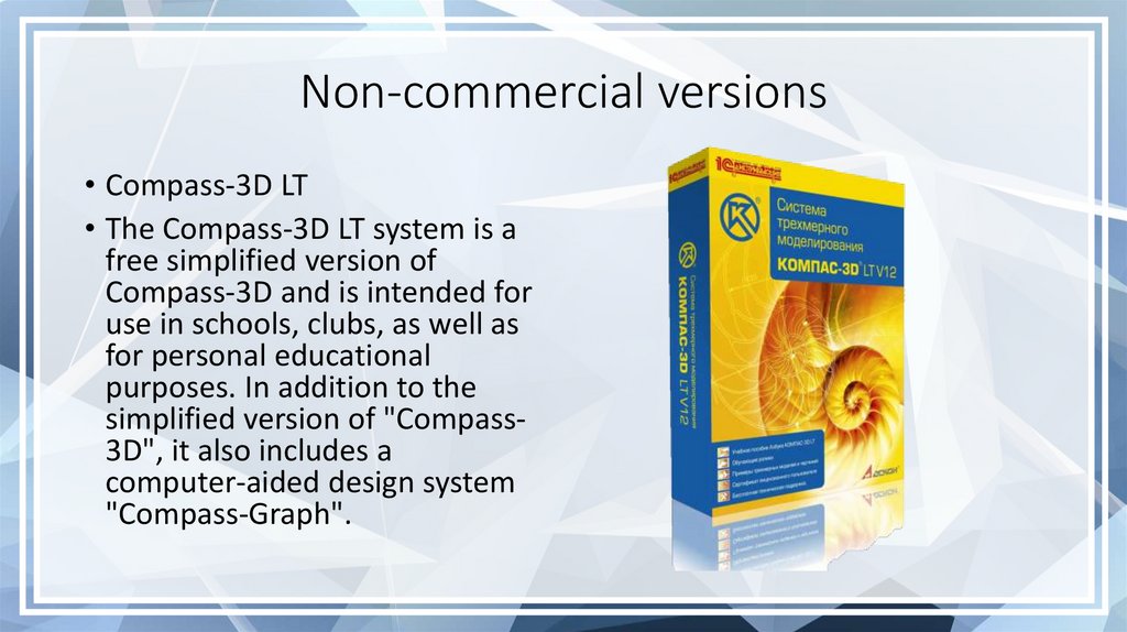
Non-commercial versions• Compass-3D LT
• The Compass-3D LT system is a
free simplified version of
Compass-3D and is intended for
use in schools, clubs, as well as
for personal educational
purposes. In addition to the
simplified version of "Compass3D", it also includes a
computer-aided design system
"Compass-Graph".
11.
Compass-3D Home• Released in 2011, the free Compass-3D Home system is designed for use in
home and educational purposes. As of 2013, the system included over 50
applications for mechanical engineering, instrumentation and construction.
The delivery with the Compass-3D Home system includes an interactive
textbook "Abc COMPASS" built into it with lessons on mastering 3D
technology. Functionally, "Compass-3D Home" differs from "Compass-3D" in
the absence of some libraries and applications.
12.
«The educational version of Compass-3D»• The system "Educational version
"Compass-3D", which is a fully
functional free version of "Compass3D", is intended for use by
schoolchildren, students and graduate
students on home computers for
educational purposes, is available for
download after registration on the
website of the educational program
Ascon. Use in the educational process
in educational institutions is not
provided. Functionally, the "Compass3D Training version" is no different
from the professional one and has a full
set of libraries and applications.
13.
The compass program and its features• COMPASS is a 3D multi-window and multi-document system.
Windows of all types of COMPASS documents can be opened
simultaneously in it - models, drawings, fragments, text and graphic
documents and specifications. Each document can be displayed in
multiple windows.
• Commands are called from the pages of the Main Menu, the context
menu, or using the buttons on the Toolbars.When working with any
type of document, the Main menu and several toolbars are displayed
on the screen: Standard, View, Current Status, Compact.
• The composition of menus and panels depends on the type of active
document. The commands that control the display of toolbars are
located in the View - Toolbar menu.
• The Library Manager is designed to manage libraries and use them.
The Message Bar displays suggestions for the current action or a
description of the selected command.
• The type of document created in the COMPASS-3D system depends
on the type of information stored in this document. Each type of
document corresponds to a file name extension and its own icon.
14.
• A part is a model of a product made of a homogeneousmaterial, without the use of assembly operations. The part file
has the m3d extension.
• Assembly is a model of a product consisting of several parts
with a given mutual position. The assembly may also include
other assemblies (subassemblies) and standard products. The
build file has the a3d extension.
• Drawing is the main type of graphic document in COMPASS-3D.
The drawing contains a graphic image of the product, the main
inscription, a frame, and sometimes additional design
elements (a sign of unspecified roughness, technical
requirements, etc.). The COMPASS-3D drawing may contain
one or more sheets. For each sheet, you can set the format,
multiplicity, orientation, etc. features. The COMPASS-3D
drawing file can contain not only drawings (in the sense of the
ESCD), but also diagrams, posters and other graphic
documents. The drawing file has the cdw extension.
• Fragment is an auxiliary type of graphic document in
COMPASS-3D. The fragment differs from the drawing in the
absence of a frame, the main inscription and other design
objects of the design document. It is used to store images that
do not need to be designed as a separate sheet (sketch
drawings, developments, etc.). In addition, the fragments also
store the created standard solutions for later use in other
documents. The fragment file has the frw extension.
15.
• Specification is a document containing information about the compositionof the assembly, presented in the form of a table. The specification is
framed and the main inscription. It is often multi-page. The specification
file has the spw extension.
• A text document is a document containing mainly textual information - a
text document. The text document is framed and the main inscription. It is
often multi-page. Explanatory notes, notices, technical specifications, etc.
can be created in a text document. The text document file has the
extension kdw.
16.
Familiarization with the system interface• An interface is a shell of a software product that carries out the
relationship between the user and the core of the program.
• The first line of the interface contains the title of the window,
where the name of the software product and the location of the
document are indicated. The second element is the Main Menu,
which offers the following groups of commands: File, Editor,
Select, View, Insert, Tools, Service, Window and Help. Each group
is a collection of commands that perform functionally similar
actions.
• The bottom two lines of the interface are occupied by the
Properties Panel and the Message Bar. The composition of the
properties panel depends on the operating mode and system
settings. Most of the commands in this panel are duplicated in
the Main Menu. This is done in order to reduce the execution
time of commands.
• Below the Main menu is a block of Toolbars. These panels
contain buttons for calling the necessary commands. Toolbars
can be combined into compact panels, the composition of which
the user can control their placement on the screen, as well as
create their own toolbars.
17.
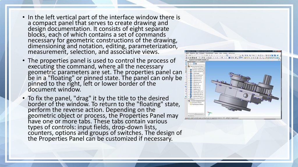
• In the left vertical part of the interface window there isa compact panel that serves to create drawing and
design documentation. It consists of eight separate
blocks, each of which contains a set of commands
necessary for geometric constructions of the drawing,
dimensioning and notation, editing, parameterization,
measurement, selection, and associative views.
• The properties panel is used to control the process of
executing the command, where all the necessary
geometric parameters are set. The properties panel can
be in a "floating" or pinned state. The panel can only be
pinned to the right, left or lower border of the
document window.
• To fix the panel, "drag" it by the title to the desired
border of the window. To return to the "floating" state,
perform the reverse action. Depending on the
geometric object or process, the Properties Panel may
have one or more tabs. These tabs contain various
types of controls: input fields, drop-down lists,
counters, options and groups of switches. The design of
the Properties Panel can be customized if necessary.
18.
• The last line of the interface window is occupied by a string ofmessages. It may reflect the following information: the system's
requirement for the data being entered at the moment, information
about the area of the screen to which the cursor is brought,
information about the current action of the system. The message
string allows you to adequately respond to system requests and
messages and avoid errors.The document window is a working field of
the drawing.
19.
• File. Activation of the menu bar is achieved by clicking on theimage of the command name. A mouse click is further
understood as clicking on the left mouse button. After clicking
the left mouse button on the File menu, a dialog box with a list
of commands will open.
• Editor. This main menu item is available if one graphic object is
selected. It triggers the process of editing the parameters of
the selected object. Another way to start editing the
parameters of an object is to double-click on this object. The
editor has 16 commands arranged in five blocks: a cancellation
block consisting of two commands, a cut-and-paste block (3
commands), a block for deleting and transforming objects (3
commands), a selection block (one command) and a block for
operations with graphic objects (7 commands).
• Select commands. On this page of the main menu there are
commands for selecting drawing or fragment objects. Using the
commands You can select objects in various ways or
combinations of them, as well as cancel the selection made.
• View. On this page of the Main Menu there are commands for
managing interface objects, drawings or fragments. This Main
Menu item has a submenu of seven commands
20.
• Insert. This menu page allows you to manage layers andcoordinate system. In fragment creation mode, it contains
a menu of two commands: Layer and Local SC. In the
drawing creation mode, it has a menu of the following
commands: View, View from the Model, Layer, Technical
Requirements, Unspecified Roughness, Main Label and
Local SC.
• Tools. This menu page contains a submenu of 6
commands. The submenu contains panels: Geometry,
Dimensions, Designations and Parameterization.
• Service. This page of the main menu contains a submenu
of 6 blocks of commands: Library Operations, Combine
into a Macro element, View Status, Measure, Calculator,
Interface Setup.
• Reference. When working on the creation of drawing and
graphic documentation, there is periodically a need for
operational reference information, especially during the
initial familiarization period. The Help system can be
accessed by pressing the last button in the Main Menu.
The Help page consists of the following sections: Content,
Contextual, What is it, Start page, Compass on the
Internet, Keyboard Commands, About the program.