


Похожие презентации:


Electrical Circuit Analogy of Stirling Type Pulse Tube Cryocooler (STPC)
1.
Electrical Circuit Analogy ofStirling Type Pulse Tube Cryocooler
(STPC)
ME 420 - Cryogenic Engineering 1
Seminar
2.
IntroductionAmong the many types of cryocoolers, the Stirling type
Pulse tube Cryocooler(STPC) has advantages of compact
structure, low vibration and high reliability.
So, it has been a topic of interest for many researchers to
analyze and optimize its cooling performance.
Electrical Circuit Analogy (ECA) is a novel method of
analyzing cryogenic systems using electrical circuits
theory.
3.
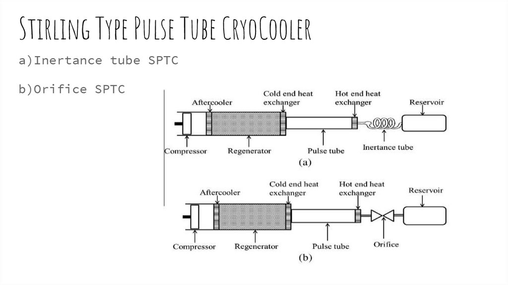
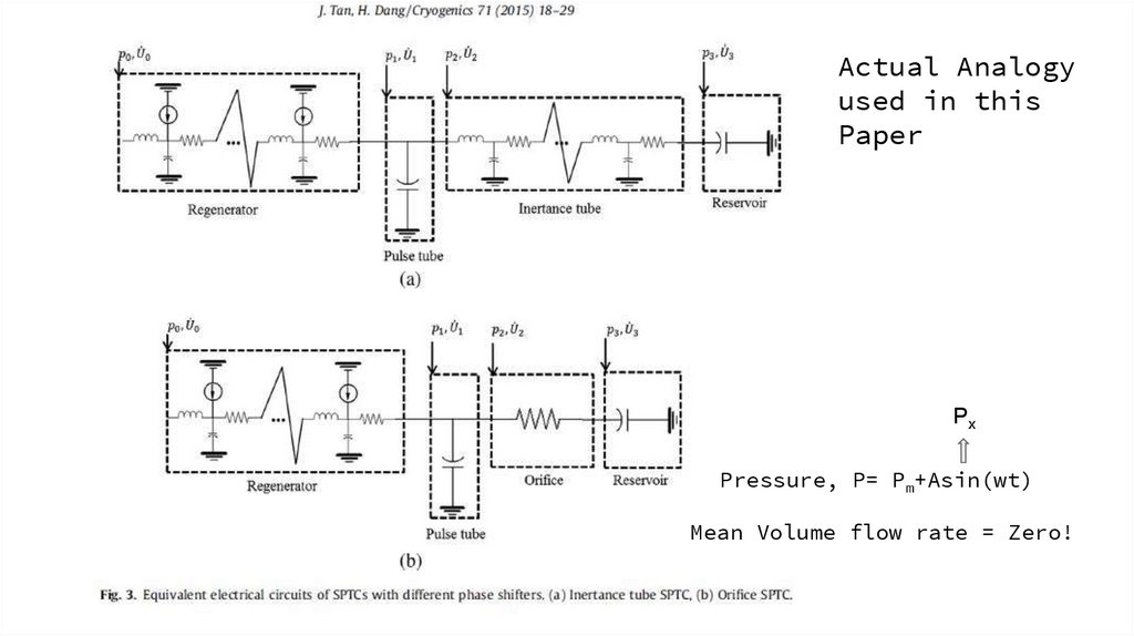
Stirling Type Pulse Tube CryoCoolera)Inertance tube SPTC
b)Orifice SPTC
4.
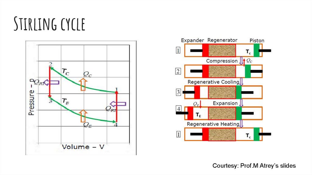
Stirling cycleCourtesy: Prof.M Atrey’s slides
5.
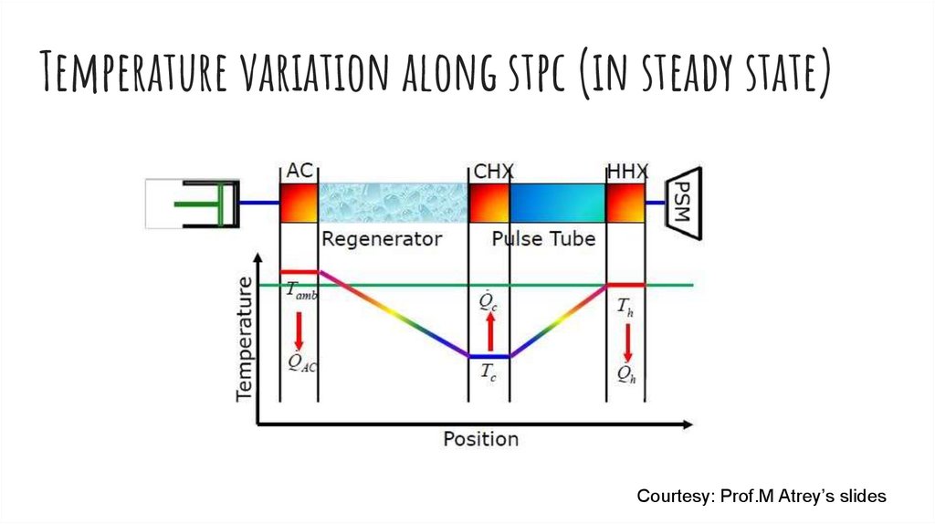
Temperature variation along stpc (in steady state)Courtesy: Prof.M Atrey’s slides
6.
Actual Analogyused in this
Paper
Px
Pressure, P= Pm+Asin(wt)
Mean Volume flow rate = Zero!
7.
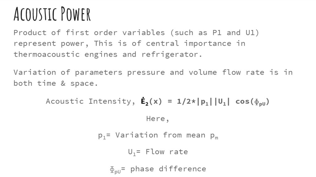
Acoustic PowerProduct of first order variables (such as P1 and U1)
represent power, This is of central importance in
thermoacoustic engines and refrigerator.
Variation of parameters pressure and volume flow rate is in
both time & space.
Acoustic Intensity, Ė2(x) = 1/2*|p1||U1| cos(ɸpU)
Here,
p1= Variation from mean pm
U1= Flow rate
ɸpU= phase difference
8.
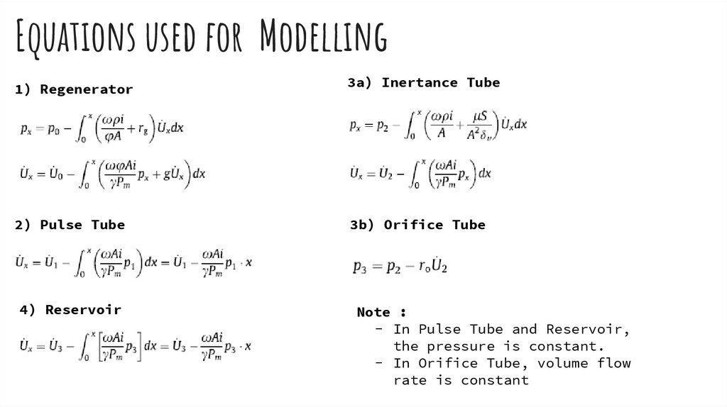
Equations used for Modelling1) Regenerator
3a) Inertance Tube
2) Pulse Tube
3b) Orifice Tube
4) Reservoir
Note :
- In Pulse Tube and Reservoir,
the pressure is constant.
- In Orifice Tube, volume flow
rate is constant
9.
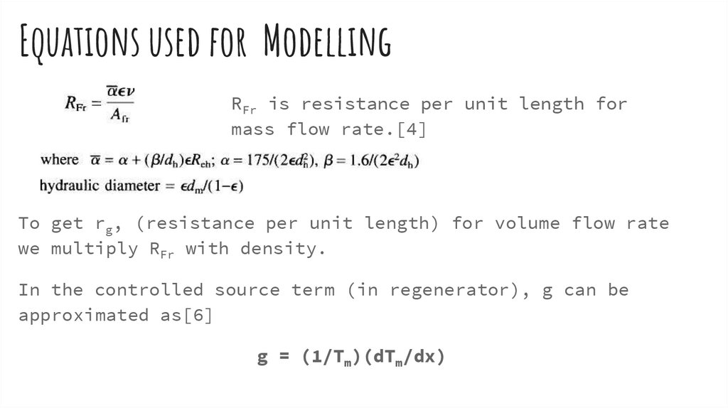
Equations used for ModellingRFr is resistance per unit length for
mass flow rate.[4]
To get rg, (resistance per unit length) for volume flow rate
we multiply RFr with density.
In the controlled source term (in regenerator), g can be
approximated as[6]
g = (1/Tm)(dTm/dx)
10.
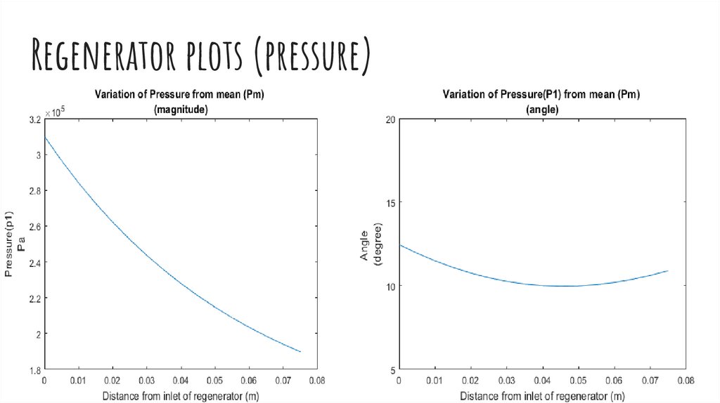
Regenerator plots (pressure)11.
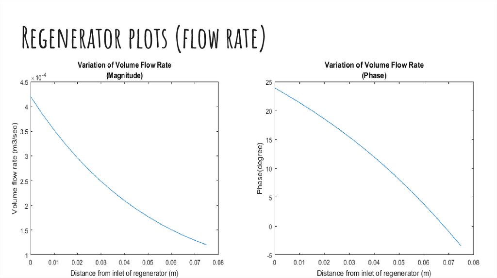
Regenerator plots (flow rate)12.
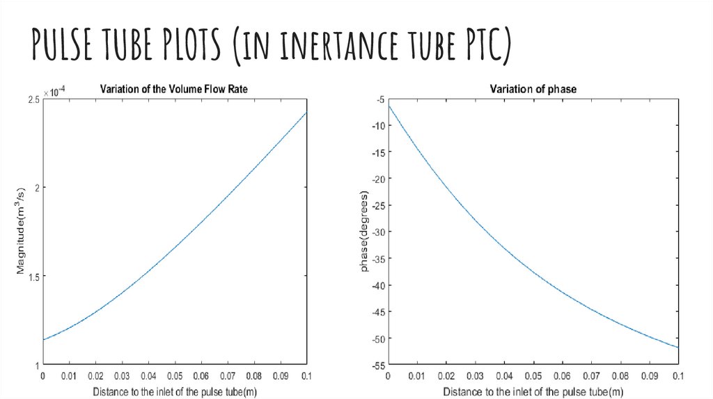
PULSE TUBE PLOTS (in inertance tube PTC)13.
PULSE TUBE PLOTS(from the paper)Look at the
difference
14.
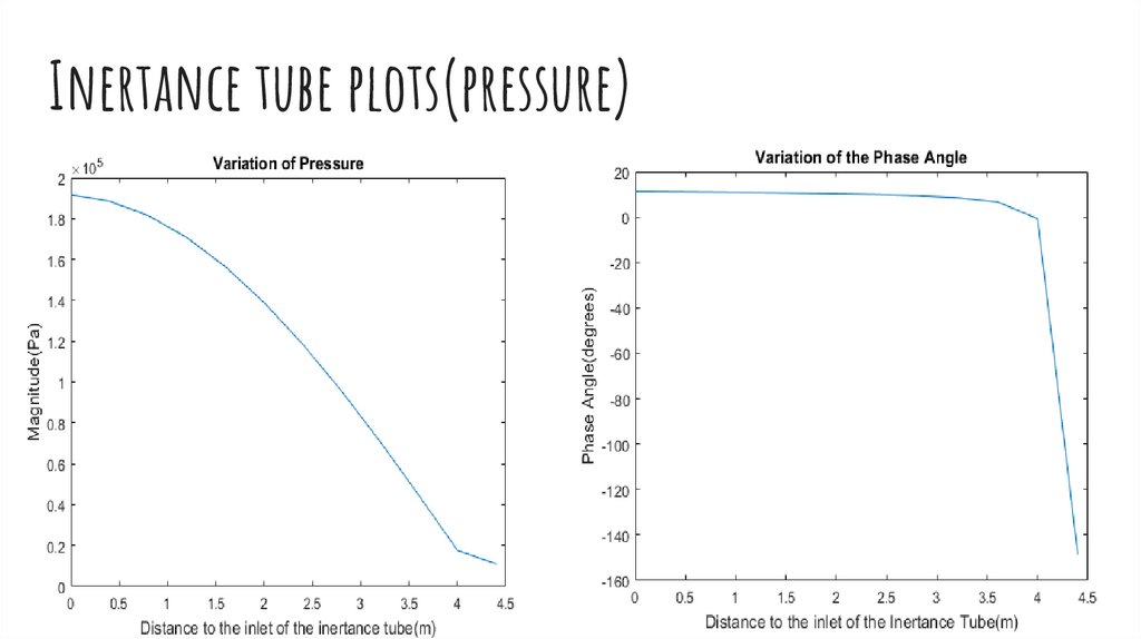
Inertance tube plots(pressure)15.
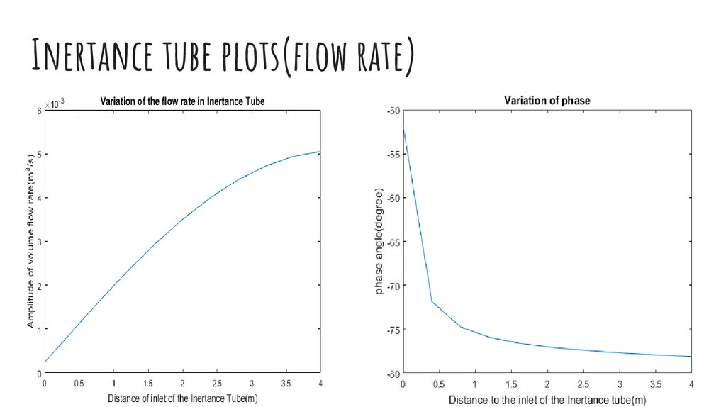
Inertance tube plots(flow rate)16.
Power loss in regeneratorPower loss happens only due to resistance but not from
compliance and inertance.
17.
The gross cooling capacity for a given (PV)0 at the hot endof the regenerator is high for a higher pressure and
lower volume flow rate as the loss is function of square
of the volume flow rate.
The volume flow rate decreases across the regenerator due
to the void volume.
Reduction in
turn would
decreasing
be done in
resistance would reduce pressure drop which in
increase the drop in volume flow rate, thus
losses.But, decreasing resistance can hardly
practice.
18.
Inertance tube (vs) Orifice TubeInertance tube is way longer(4.9m vs just a few mm) than
Orifice plate. The effects of pressure change take time
to propagate over the length of inertance tube. Also
experimentally it was observed that inertance tube was
better in terms of gross cooling capacity.
When the fluid in the tube is expanded, the fluid in the
inertance is still moving right. In this situation, a
fluid element in the tube moves less during both the
compression and the expansion phase than in the same
situation in an orifice pulse tube.
19.
references1.”An electrical circuit analogy model for analyses and
optimizations of the Stirling-type pulse tube cryocooler”,
Jun Tan, Haizheng Dang, Cryogenics 71 (2015) 18–29 -MAIN
PAPER
2.http://in.mathworks.com/help/symbolic/solve-a-singledifferential-equation.html
3.https://in.mathworks.com/help/symbolic/int.html
20.
4.Huang BJ, Chuang MD. System design of orifice pulse-tuberefrigerator using linear flow network analysis. Cryogenics
1996;36:889–902.
5.Comparison of the orifice, inertance and double inlet
pulse tube refrigerator, S.C.M. Aerts August 1999
6.”Thermoacoustics- A unifying perspective for some engines
and Refrigerators”, G.W.Swift
21.
Thanks!Gowtham Kuntumalla
- 140100091
Krishna Sandeep
- 140100104
Mohith Sai Nag
- 140100107
22.
Work Done till dateWe studied the working of a pulse tube cryocooler.
Tried deriving the relation between pressure and volume
flow rate from continuity and momentum equations
Looked at proposed electrical models of individual
components of the STPC.
Used MATLAB for simulating these electrical analogies and
obtained plots close to the actual plots.
Analytically studied the effect of phase between P,V(dot)
and relative magnitudes. How PV power is affected.
23.
Code in speaker note below and at the following link.https://github.com/gowthamkuntumalla/Cryogenics-ElectricalAnalogy-of-Pulse-tube-cryocooler