


 Электроника
Похожие презентации:

")


, Impedance (Z) and resonance")


Industrial Electronics. Fundamentals of Electric Circuits
1.
Industrial ElectronicsLI LI LI
李莉莉
浙江海洋学院
2014-10-09
2.
Chapter 1Fundamentals of Electric Circuits
Circuit is a current path, it is needed for
some electrical equipment by certain
Or elements combined in a certain way up.
3.
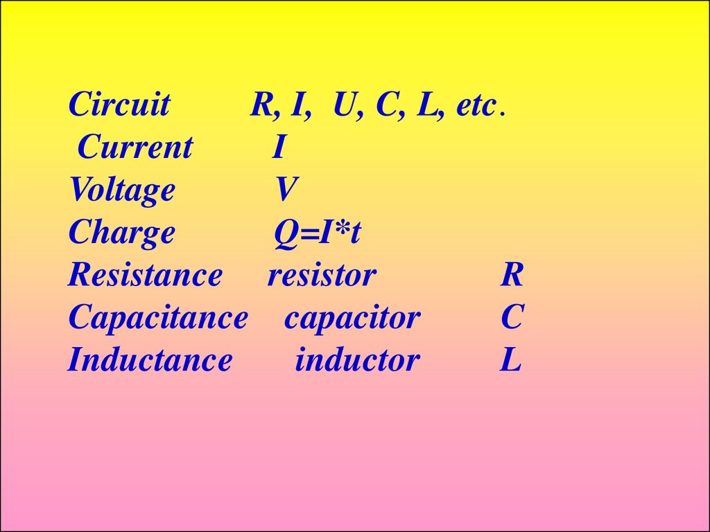
CircuitR, I, U, C, L, etc.
Current
I
Voltage
V
Charge
Q=I*t
Resistance resistor
R
Capacitance capacitor
C
Inductance
inductor
L
4.
Learning Objectives:1. Identify the principal elements of electric circuits:
nodes, loops, meshes, branches, voltage and
current sources;
2. Apply Kirchhoff’s laws to simple electric circuits
and derive the basic circuit equations.
3. Compute the power delivered or absorbed by
circuit elements.
4. Apply the voltage and current divider laws to
calculate unknown variables in simple series,
parallel, and series-parallel circuits.
5.
§1 Fundamentals of Electric Circuits§ 1-1 1. Circuit models 电路模型
The voltage source
Two active 有源 models
The current source
Three passive(无源 models
The resistor
The inductor
The capacitor
6.
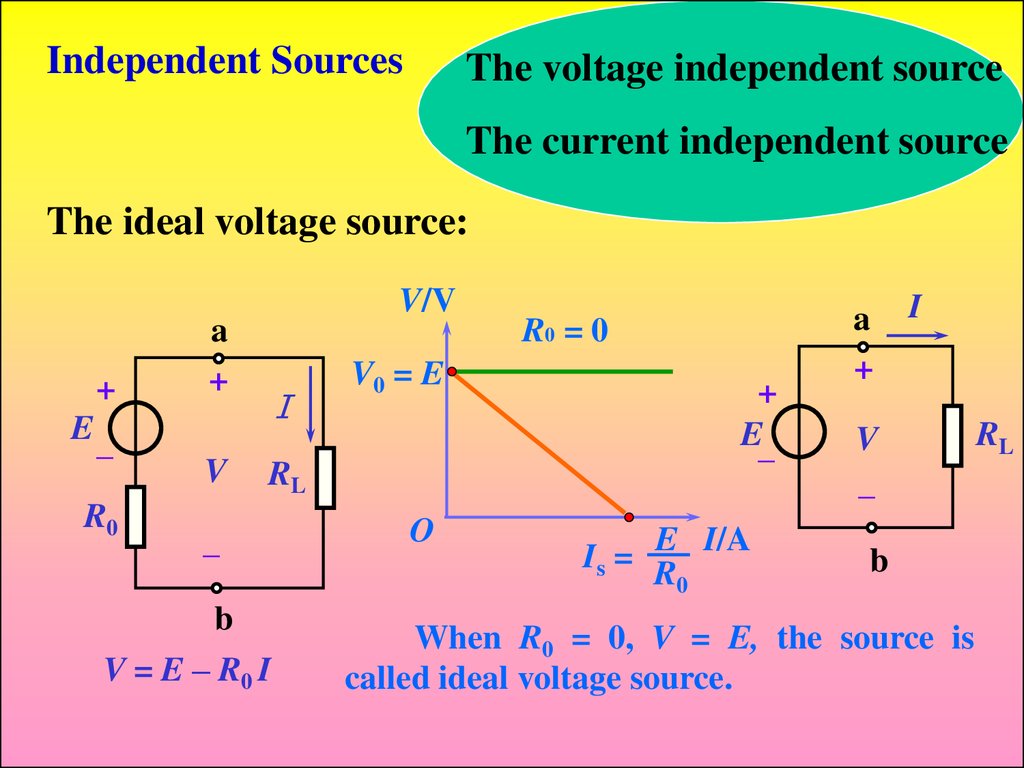
Independent SourcesThe voltage independent source
The current independent source
The ideal voltage source:
+
E_
R0
V/V
a
+
V
I
V0 = E
RL
_
b
V = E – R0 I
O
R0 = 0
+
E_
E I/A
Is = R
0
a
+
I
V
_
b
When R0 = 0, V = E, the source is
called ideal voltage source.
RL
7.
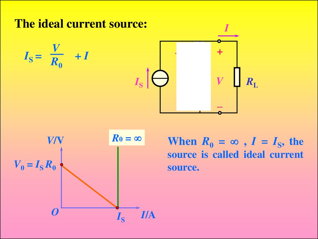
The ideal current source:V
IS = R
0
I
V
R0
+I
IS
R0
+
V
RL
–
V/V
R0 =
source is called ideal current
source.
V0 = IS R0
O
When R0 = , I = IS, the
IS
I/A
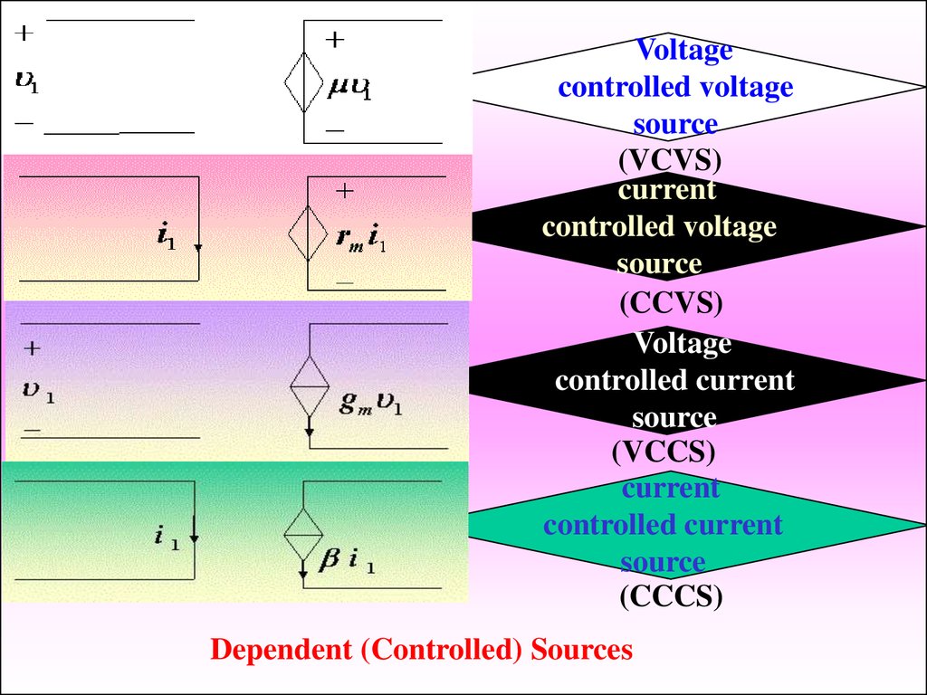
8.
Voltagecontrolled voltage
source
(VCVS)
current
controlled voltage
source
(CCVS)
Voltage
controlled current
source
(VCCS)
current
controlled current
source
(CCCS)
Dependent (Controlled) Sources
9.
2. Network variables (网络变量)The systems of units (单位制) : International system
of units; SI unit
Length [meter] (m)
Time [second] (s)
Mass [kilogram] (kg)
(1) Current -- i(t), I ----
(A, mA, μA...)
The net time-rate of transference (传递) of charge is
referred to as the flow of current.
t
dq
i(t )
q( t ) i ( )d
dt
d
: differentiation
dt
t
(2) Energy (or work) -- w(t) (J)
: int egration
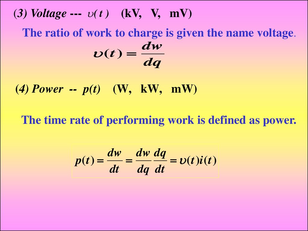
10.
(3) Voltage --- ( t ) (kV, V, mV)The ratio of work to charge is given the name voltage.
dw
(t )
dq
(4) Power -- p(t)
(W, kW, mW)
The time rate of performing work is defined as power.
dw dw dq
p( t )
( t )i ( t )
dt
dq dt
11.
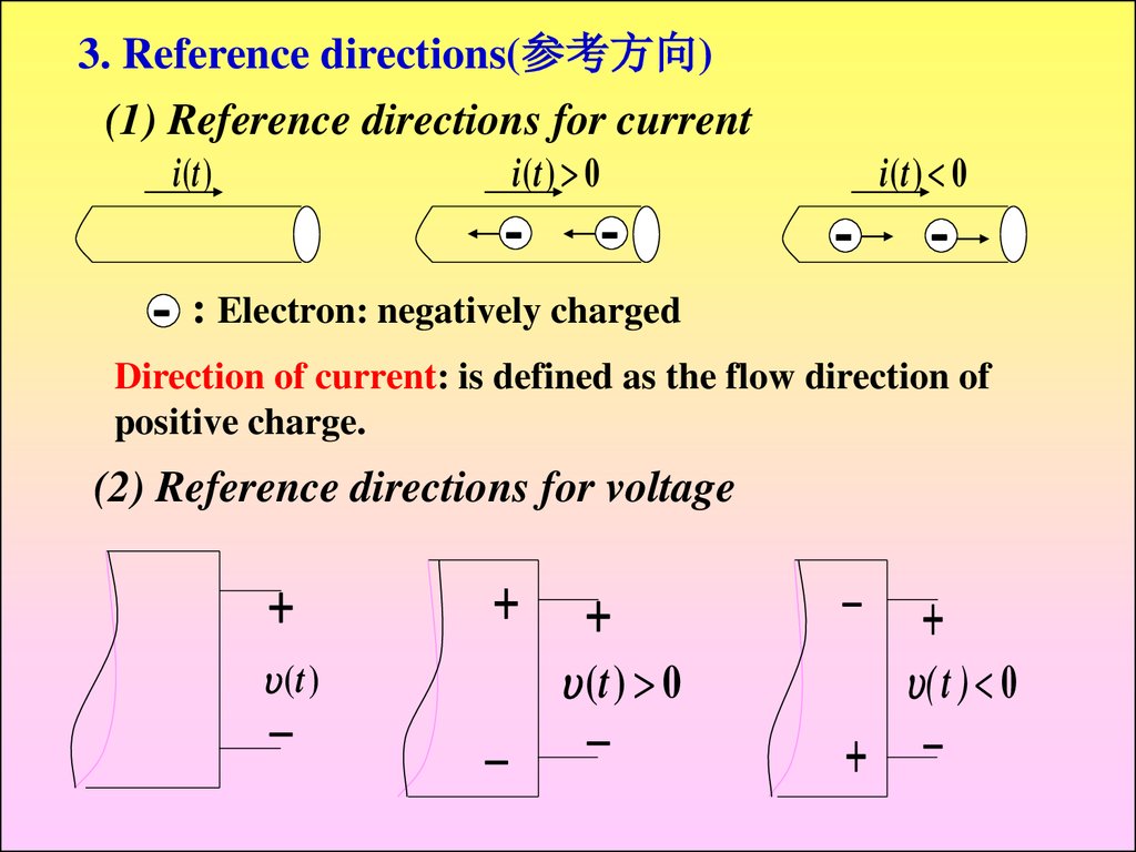
3. Reference directions(参考方向)(1) Reference directions for current
i(t ) 0
i (t )
: Electron: negatively charged
i(t ) 0
Direction of current: is defined as the flow direction of
positive charge.
(2) Reference directions for voltage
(t ) 0
(t )
( t ) 0
7
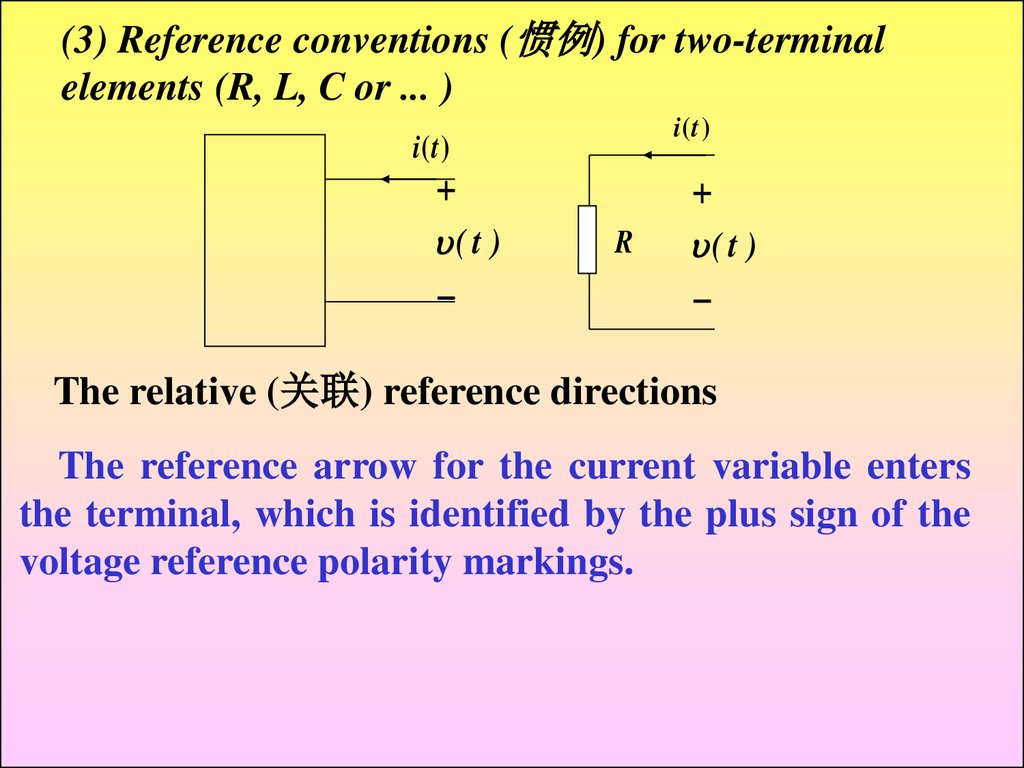
12.
(3) Reference conventions (惯例) for two-terminalelements (R, L, C or ... )
i (t )
i (t )
( t )
R
( t )
The relative (关联) reference directions
The reference arrow for the current variable enters
the terminal, which is identified by the plus sign of the
voltage reference polarity markings.
7
13.
(4) The reference for poweri (t )
( t )
p(t)>0
p( t ) ( t )i ( t )
the power absorbed by the element.
p(t)<0 the negative power absorbed by the
element, or it is actually generating power
and delivering it to some external element.
14.
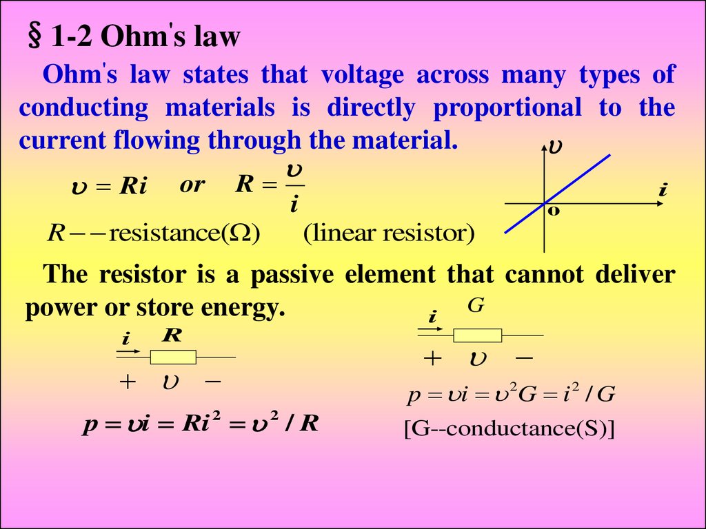
§1-2 Ohm's lawOhm's law states that voltage across many types of
conducting materials is directly proportional to the
current flowing through the material.
Ri or R
i
R resistance(Ω)
i
0
(linear resistor)
The resistor is a passive element that cannot deliver
G
power or store energy.
i
i
R
p i Ri 2 2 / R
p i 2G i 2 / G
[G--conductance(S)]
15.
The current through and voltage across a resistormust both vary with time in the same manner.
If : R 10Ω, (t ) 2sin100tV
We have
i / R 0.2sin100tA
and
p i 0.4(sin100t ) 2W
p
p
i
0
T
t
We define a "short circuit" as a resistance of zero ohms.
We define a "open circuit" as an infinite resistance.
16.
§1-3 Kirchhoff's lawsA point at which three or more elements have
common connection is called a node(节点).
a 1
1
3
3
2
b
2
Suppose that we start at one node in a network and
move through a simple element to the node at the
other…, if no node was encountered more than once,
then the set of nodes and elements that we have passed
through is defined as a path 路径 .
17.
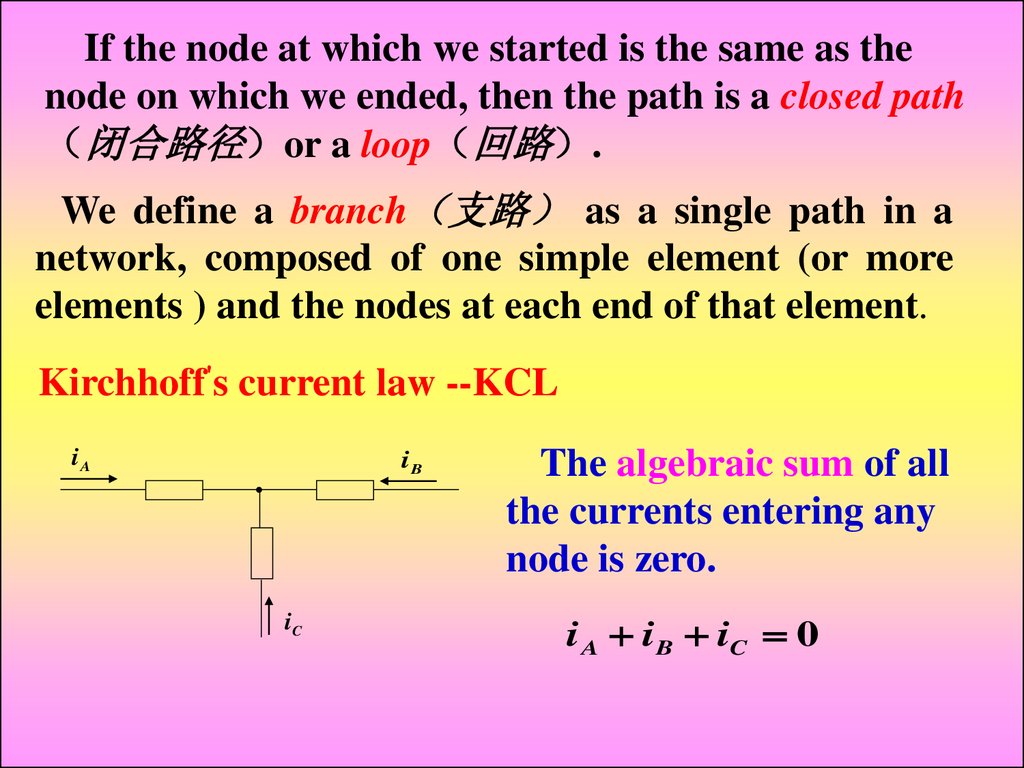
If the node at which we started is the same as thenode on which we ended, then the path is a closed path
闭合路径 or a loop 回路 .
We define a branch 支路 as a single path in a
network, composed of one simple element (or more
elements ) and the nodes at each end of that element.
Kirchhoff's current law --KCL
iA
iB
iC
The algebraic sum of all
the currents entering any
node is zero.
i A i B iC 0
18.
The algebraic sum of all the currents entering anynode is zero.
The algebraic sum of all the currents leaving a node
is zero.
or:
The algebraic sum of all the currents entering a
node must equal the algebraic sum of all the currents
leaving the node.
i1 i2 i3 i4 0
i2
i1 i2 i3 i4 0
i1
i4
i3
i1 i2 i3 i4
The three equivalent equations
19.
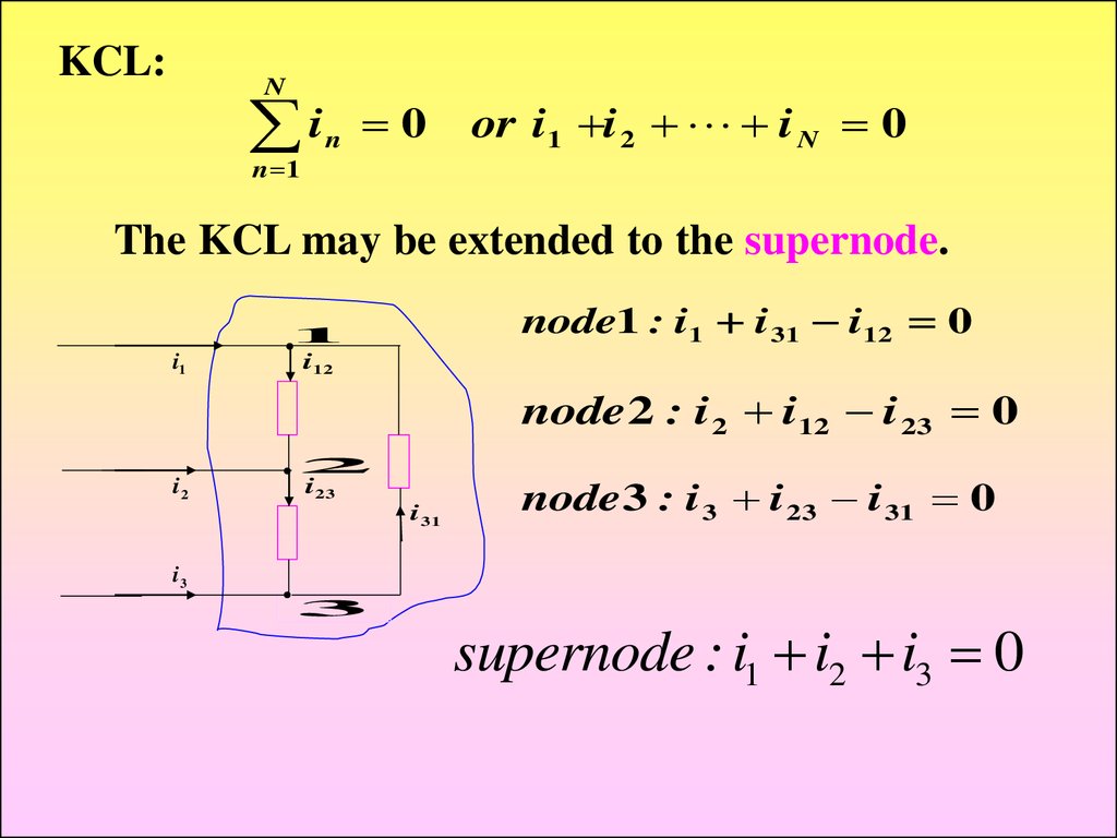
KCL:N
i
n 1
n
0
or i1 i 2 i N 0
The KCL may be extended to the supernode.
i1
node1 : i1 i 31 i12 0
1
i12
node 2 : i 2 i12 i 23 0
i2
2
i 23
i 31
node 3 : i 3 i 23 i 31 0
i3
3
supernode : i1 i2 i3 0
20.
Loop1Loop2
Loop3
A mesh (网孔 is a loop that does not contain other
loops.
3 loops: loop1, loop2, loop3;
2 meshes: loop1, loop2
21.
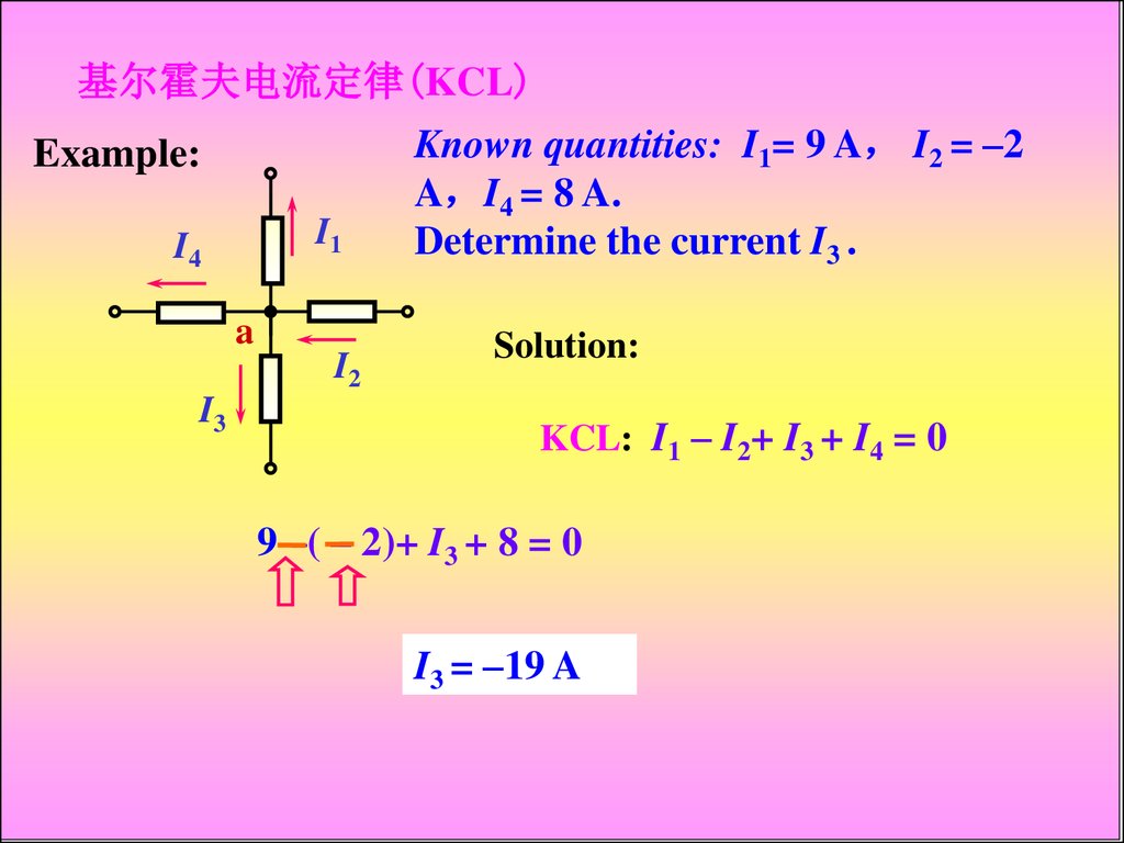
基尔霍夫电流定律(KCL)Example:
I1
I4
a
I2
I3
Known quantities: I1= 9 A I2 = –2
A I4 = 8 A.
Determine the current I3 .
Solution:
KCL: I1 – I2+ I3 + I4 = 0
9 –( – 2)+ I3 + 8 = 0
I3 = –19 A
22.
Kirchhoff's voltage law--KVLThe algebraic sum of the voltage around any closed
path in a circuit is zero.
A
clokwise : 1 2 0
1
2
counterclokwise : 1 2 0
B
N
KVL:
n 1
2
3
1
n
0
or
1 2 N 0
clokwise : 1 2 3 0
counterclokwise : 1 2 3 0
23.
§1-4 Series resistors and voltage divider ruleEquivalent series
resistance
i
i
R1
1
2
Req R1 R2
+
R2
R
–
Voltage
divider
R1
1 R1i R1
R1 R2 R1 R2
R2
2 R2 i R2
R1 R2 R1 R2
24.
§1-5 Parallel resistors and current divider ruleEquivalent parallel
resistance
i
i1
R1
i
i2
R2
+
R
R1 R2
Req
R1 R2
–
Current
divider
R1 R2
i
R2
R1 R2
i1
i
R1
R1
R1 R2
R1
i2
i
R1 R2
25.
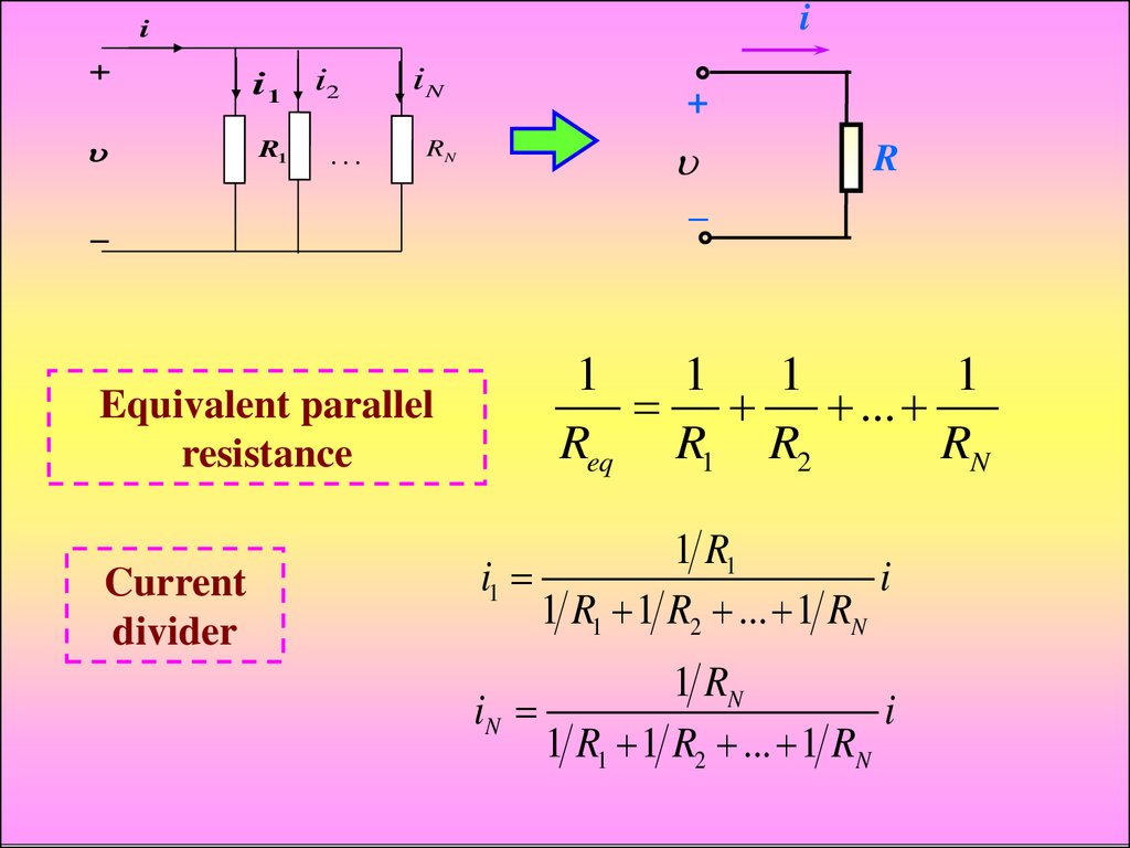
ii
i1
R1
i2
…
iN
RN
Equivalent parallel
resistance
Current
divider
+
R
–
1
1 1
1
...
Req R1 R2
RN
1 R1
i1
i
1 R1 1 R2 ... 1 RN
1 RN
iN
i
1 R1 1 R2 ... 1 RN
26.
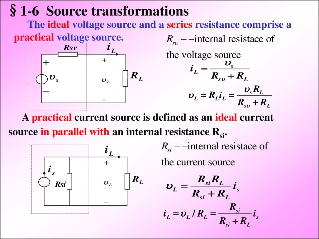
§1-6 Source transformationsThe ideal voltage source and a series resistance comprise a
practical voltage source.
Rs internal resistace of
Rsv
iL
the voltage source
s
L
iL
RL
s
Rs RL
L RL i L
s RL
Rs RL
A practical current source is defined as an ideal current
source in parallel with an internal resistance Rsi.
Rsi internal resistace of
i
L
is
Rsi
L
the current source
RL
Rsi RL
is
Rsi RL
Rsi
i L L / RL
is
Rsi RL
L
27.
We shall define two sources as being equivalent ifeach produces identical current and identical voltage
in any loads which is placed across its terminals.
s
Rsi
is
Conditions of equivalence: i L
Rs RL
s Rs i s
Rs Rsi Rs
s
iL
iL
Rsv
L
Rsi RL
is
RL
Rsi
L
RL
28.
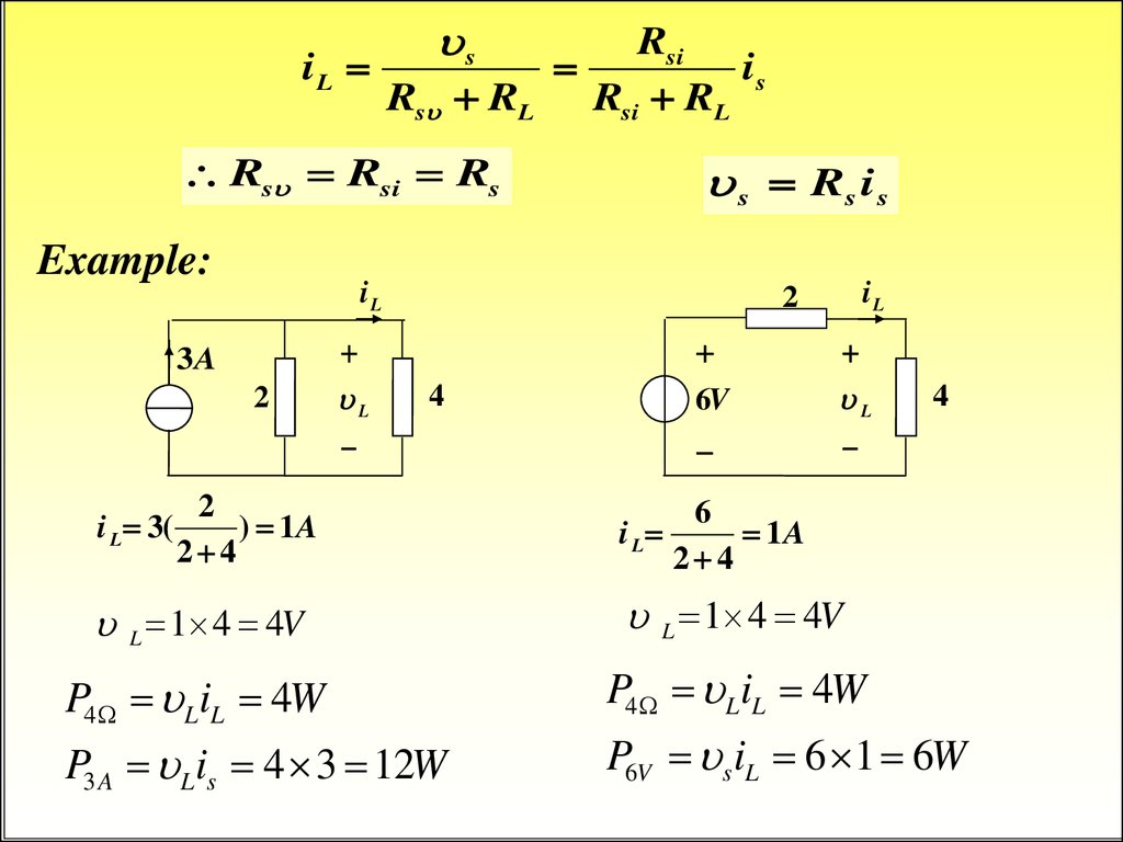
sRsi
iL
is
Rs RL
Rsi RL
Rs Rsi Rs
Example:
s Rs i s
iL
3A
2
L
iL
2
6V
L
4
2
i L 3(
) 1A
2 4
6
i L
1A
2 4
L 1 4 4V
L 1 4 4V
P4 LiL 4W
P4 LiL 4W
P3 A Lis 4 3 12W
4
P6V s iL 6 1 6W