


 Строительство
Похожие презентации:


")


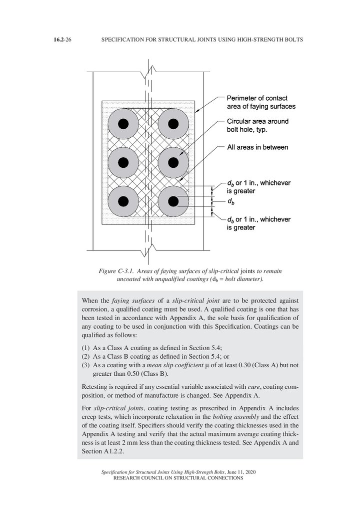
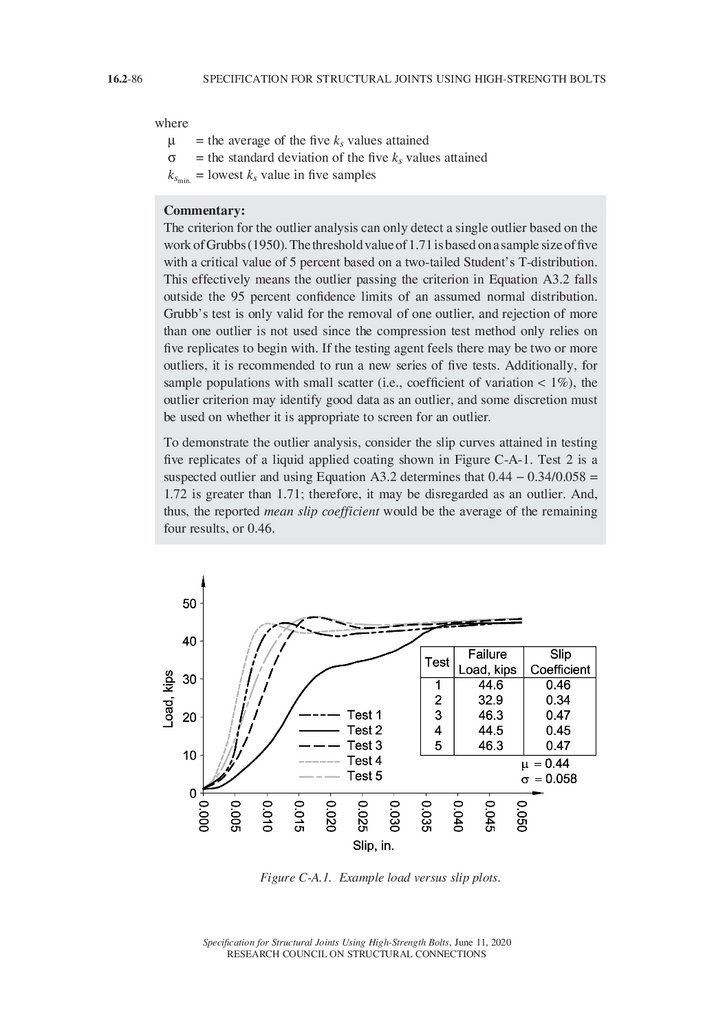
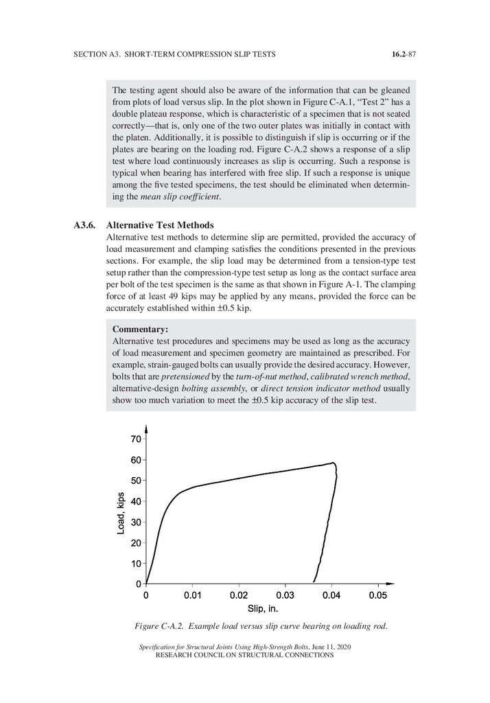
Structural Joints. Using HighStrength Bolts
1.
Specification forStructural Joints
Using HighStrength Bolts
June 11, 2020
Supersedes the August 1, 2014
Specification for Structural Joints Using High-Strength Bolts
Prepared by RCSC Committee A.1—Specifications and
approved by the Research Council on Structural Connections
2.
3.
Specification forStructural Joints
Using HighStrength Bolts
June 11, 2020
Supersedes the August 1, 2014
Specification for Structural Joints Using High-Strength Bolts
Prepared by RCSC Committee A.1—Specifications and
approved by the Research Council on Structural Connections
www.boltcouncil.org
RESEARCH COUNCIL ON STRUCTURAL CONNECTIONS
c/o AISC, 130 E Randolph Street, Suite 2000, Chicago, Illinois 60601
4.
16.2-ii© RCSC 2020
by
Research Council on Structural Connections
All rights reserved. This book or any part thereof must not be reproduced in any form without the written permission of the publisher.
The information presented in this publication has been prepared in accordance with recognized engineering principles and is for general information only. While it is believed to
be accurate, this information should not be used or relied upon for any specific application
without competent examination and verification of its accuracy, suitability, and applicability
by a licensed professional engineer, designer, or architect. The publication of the material
contained herein is not intended as a representation or warranty on the part of the Research
Council on Structural Connections or of any other person named herein, that this information is suitable for any general or particular use or of freedom from infringement of any
patent or patents. Anyone making use of this information assumes all liability arising from
such use.
Caution must be exercised when relying upon other specifications and codes developed by
other bodies and incorporated by reference herein since such material may be modified after
the printing of this edition. The Council bears no responsibility for such material it incorporates by reference at the time of the initial publication of this edition.
Printed in the United States of America
Specification for Structural Joints Using High-Strength Bolts, June 11, 2020
RESEARCH COUNCIL ON STRUCTURAL CONNECTIONS
5.
16.2-iiiPREFACE
The purpose of the Research Council on Structural Connections (RCSC) is:
(1) To stimulate and support such investigation as may be deemed necessary and valuable to determine the suitability, strength, and behavior of various types of structural
connections;
(2) To promote the knowledge of economical and efficient practices relating to such
structural connections; and
(3) To prepare and publish related specifications and such other documents as necessary
to achieve its purpose.
The Council membership consists of qualified structural engineers from academic and research
institutions, practicing design engineers, representatives of suppliers and manufacturers of
bolting components, steel fabricators, steel erectors, contractors, associations, and codewriting bodies.
The first Specification approved by the Council, called the Specification for Assembly of
Structural Joints Using High Tensile Steel Bolts, was published in January 1951. Since that time
the Council has published 18 successive editions. Each was developed through the deliberations and approval of the full Council membership and based upon past successful usage,
advances in the state of knowledge, and changes in engineering design practice. This edition
of the Council’s Specification for Structural Joints Using High-Strength Bolts continues the
tradition of earlier editions. The most significant changes are listed below.
1. Significant additions to Glossary (bolting assembly, bolting component, bolt tension
measurement device, calibrated gap, cure, initial tension, initial torque, job inspection
gap, matched bolting assembly, spline end, sufficient thread engagement).
2. Discussion of thermal break joints in commentary.
3. Expanded list of items to be addressed by engineer of record (EOR) in commentary.
4. Addition of 144 ksi, ASTM F3148 matched bolting assemblies.
5. Adoption of “Group” 120, 144, and 150 to categorize bolt strengths.
6. Short fully threaded bolts are to be designed with threads in the shear plane. (Table
2.5).
7. Expanded discussion of “alternative design” bolting components, bolting assemblies,
and pretensioning methods (2.12).
8. Removed requirement and prohibits hand wire brushing of galvanized faying surfaces
in slip-critical joints.
9. Added ASTM A1059 coating for DTIs.
10. Added zinc-aluminum coatings, ASTM F2833 and ASTM F3019.
11. Expanded discussion of storage and lubrication (2.10).
12. Moved discussion of “reuse” to new and expanded section (2.11).
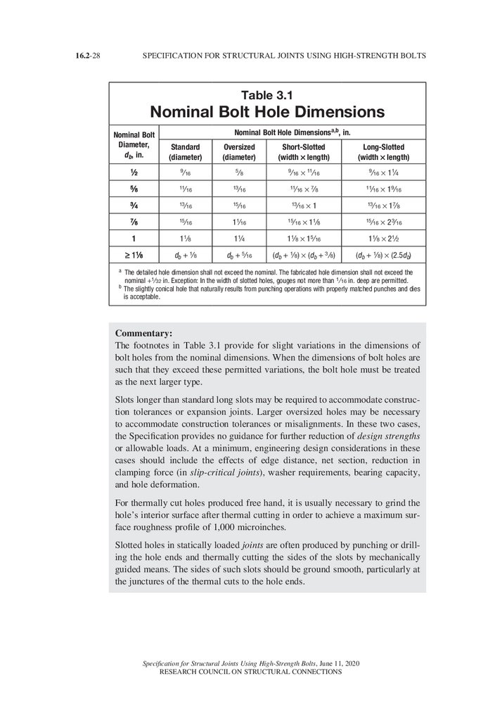
13. Increased standard bolt hole diameter and slot widths for bolts 1-in. in diameter and
greater (Table 3.1).
14. Table 8.1 Minimum Bolt Pretension moved to Table 5.2 in design.
15. Revised values for pre-installation verification testing and for pretension for Group
120 bolts larger than 1 in. diameter (Table 5.2).
Specification for Structural Joints Using High-Strength Bolts, June 11, 2020
RESEARCH COUNCIL ON STRUCTURAL CONNECTIONS
6.
16.2-ivSPECIFICATION FOR STRUCTURAL JOINTS USING HIGH-STRENGTH BOLTS
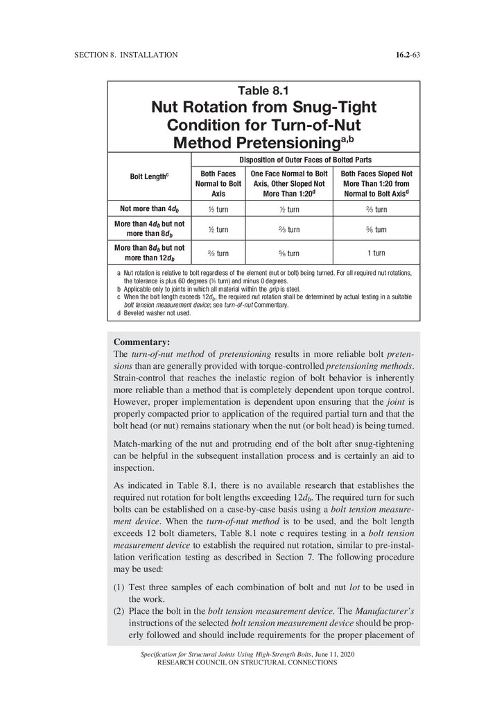
16. Revised tolerance for turn-of-nut (Table 8.1).
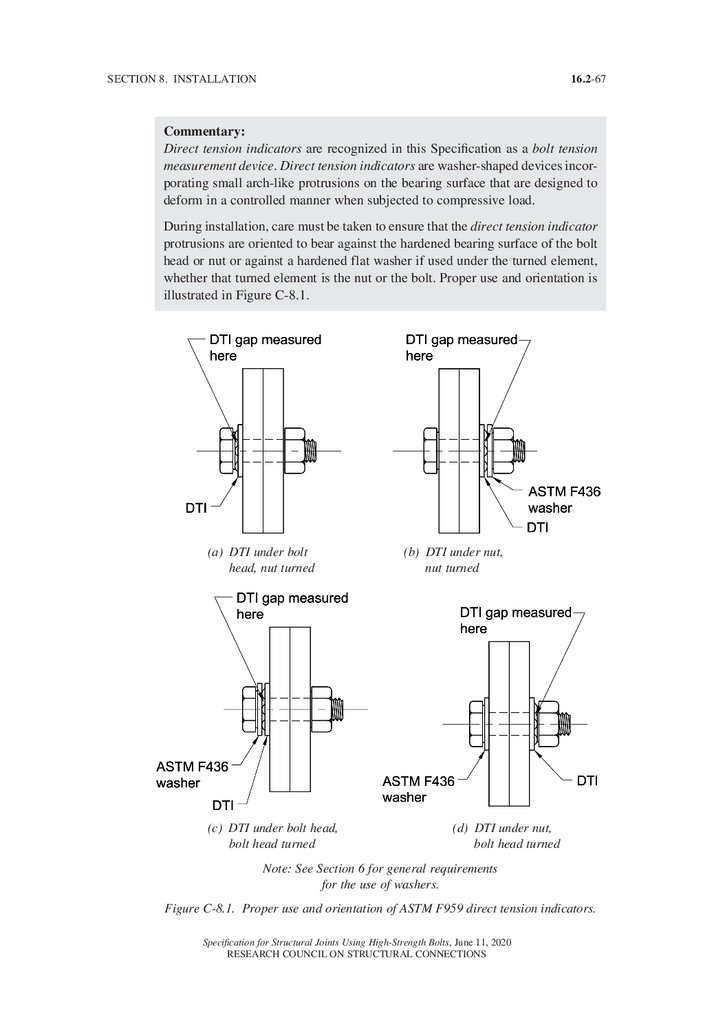
17. Corrected figure for DTI installation and washer requirements to agree with specification (Figure C-8.1, 8.2.4).
18. Clarified purpose and requirements for pre-installation verification testing (7).
19. Provided steps comprising pre-installation verification testing (7.2).
20. Provided steps for performing pretensioning using all five methods (8.2).
21. Added new “combined method” pretensioning method and inspection requirements
for this method (8.2.5, 9.2.5).
22.
Added instructions for determining required rotation when bolt length exceeds
12 bolt diameters (8.2.1 commentary).
23. Restricted the use of calibrated wrench pretension method to rotation of the nut
(8.2.2).
24. Clarified numbers of gaps permitted and required for DTI pretensioning and inspection (8.2.4, 9.2.4).
25. Added reference to AISC Specification for Structural Steel Buildings Chapter N,
Quality.
26. Added essential variables to Appendix A slip coefficient tests.
27. Added effective period for slip resistance test validity.
In addition, many editorial changes to the 2014 publication of the Specification are reflected
in this latest edition.
The Council wishes to express their gratitude to Gian A. Rassati for his extensive and diligent work managing the changes through many revisions and multiple ballots. His service
to the Council has been extraordinary and was instrumental for publication of this edition
of the Specification.
By the Research Council on Structural Connections,
Officers
Salim V. Brahimi
Robert Shaw
Jonathan McGormley
Chair Vice Chair Secretary/Treasurer
Directors
Toby Anderson
Curtis L. Mayes
Carly McGee
Gian A. Rassati
Task Groups
1 General Requirements
2 Products and Parts
3 Design
4 Installation
5 Inspection
Gian A. Rassati
Toby Anderson
James A. Swanson
Heath E. Mitchell/Chad M. Larson
Daniel J. Kaufman
Thomas J. Schlafly
Todd C. Ude
Specification for Structural Joints Using High-Strength Bolts, June 11, 2020
RESEARCH COUNCIL ON STRUCTURAL CONNECTIONS
7.
16.2-vPREFACE
Committees
A1
Specification
A2/A4 Research, Education and Projects
A3
Membership and Funding
A5
Organizational Liaison
B
Editorial
Staff Support
Members
Rodney L. Baxter
Jason Bell
Peter C. Birkemoe
David Bogaty
David Bornstein
Rich Brown
Garret O. Byrne
Chad T. Case
Derrick Castle
Jason Chadee
Helen Chen
Robert J. Connor
Bastiaan Cornelissen
Chris Curven
Nick E. Deal
Douglas B. Ferrell
John W. Fisher
Karl H. Frank
Michael C. Friel
Christopher Garrell
Albert Gelles
Bill Germuga
Rodney D. Gibble
Larry F. Kruth
Todd C. Ude
Salim V. Brahimi
Thomas J. Schlafly
Rachel Jordan
Philip A. Goldsby
Brian Goldsmith
Matthew Haaksma
Jerome F. Hajjar
Robert A Hay III
Charles J. Kanapicki
Peter F. Kasper
Daniel J. Kaufman
James S. Kennedy
Thomas J. Langill
Chad M. Larson
Donald Livi
Mike Marian
John C. Marvin
Ronnie Medlock
Jinesh K. Mehta
Heath E. Mitchell
Thomas M. Murray
James Neeley
Christian Noveral
Justin Ocel
Sarah Olthof
Anna Petroski
Brad Porter
Randy Reagan
Jordan Richardson
Joseph T. Ridgway
Sougata Roy
Jeremy Ruggio
Michael Samuels
Ben Seinola
Rachel Shanley
David F. Sharp
Victor Shneur
W. Lee Shoemaker
Nicholas Sovell
Mritunjaya Srivastava
Carlos Suarez Gullardo
James A. Swanson
Thomas S. Tarpy, Jr.
Chris Thorsen
Raymond H.R. Tide
Carmen Vertullo
Dan Wrobleski
Natasha Zamani
Specification for Structural Joints Using High-Strength Bolts, June 11, 2020
RESEARCH COUNCIL ON STRUCTURAL CONNECTIONS
8.
16.2-viTABLE OF CONTENTS
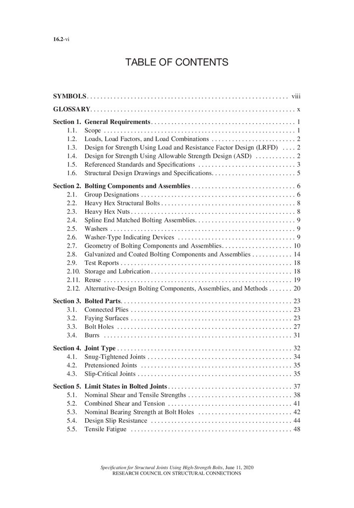
SYMBOLS. . . . . . . . . . . . . . . . . . . . . . . . . . . . . . . . . . . . . . . . . . . . . . . . . . . . . . . . . . . . . viii
GLOSSARY. . . . . . . . . . . . . . . . . . . . . . . . . . . . . . . . . . . . . . . . . . . . . . . . . . . . . . . . . . . . . x
Section 1. General Requirements. . . . . . . . . . . . . . . . . . . . . . . . . . . . . . . . . . . . . . . . . . . 1
1.1. Scope . . . . . . . . . . . . . . . . . . . . . . . . . . . . . . . . . . . . . . . . . . . . . . . . . . . . . . . . . 1
1.2. Loads, Load Factors, and Load Combinations . . . . . . . . . . . . . . . . . . . . . . . . . 2
1.3. Design for Strength Using Load and Resistance Factor Design (LRFD) . . . . 2
1.4. Design for Strength Using Allowable Strength Design (ASD) . . . . . . . . . . . . 2
1.5. Referenced Standards and Specifications . . . . . . . . . . . . . . . . . . . . . . . . . . . . . 3
1.6. Structural Design Drawings and Specifications. . . . . . . . . . . . . . . . . . . . . . . . . 5
Section 2. Bolting Components and Assemblies. . . . . . . . . . . . . . . . . . . . . . . . . . . . . . . 6
2.1. Group Designations. . . . . . . . . . . . . . . . . . . . . . . . . . . . . . . . . . . . . . . . . . . . . . 6
2.2. Heavy Hex Structural Bolts. . . . . . . . . . . . . . . . . . . . . . . . . . . . . . . . . . . . . . . . 8
2.3. Heavy Hex Nuts. . . . . . . . . . . . . . . . . . . . . . . . . . . . . . . . . . . . . . . . . . . . . . . . . 8
2.4. Spline End Matched Bolting Assemblies. . . . . . . . . . . . . . . . . . . . . . . . . . . . . . 9
2.5. Washers . . . . . . . . . . . . . . . . . . . . . . . . . . . . . . . . . . . . . . . . . . . . . . . . . . . . . . . 9
2.6. Washer-Type Indicating Devices . . . . . . . . . . . . . . . . . . . . . . . . . . . . . . . . . . . 9
2.7. Geometry of Bolting Components and Assemblies. . . . . . . . . . . . . . . . . . . . . 10
2.8. Galvanized and Coated Bolting Components and Assemblies. . . . . . . . . . . . 14
2.9. Test Reports. . . . . . . . . . . . . . . . . . . . . . . . . . . . . . . . . . . . . . . . . . . . . . . . . . . 18
2.10. Storage and Lubrication. . . . . . . . . . . . . . . . . . . . . . . . . . . . . . . . . . . . . . . . . . 18
2.11. Reuse . . . . . . . . . . . . . . . . . . . . . . . . . . . . . . . . . . . . . . . . . . . . . . . . . . . . . . . . 19
2.12. Alternative-Design Bolting Components, Assemblies, and Methods. . . . . . . 20
Section 3. Bolted Parts. . . . . . . . . . . . . . . . . . . . . . . . . . . . . . . . . . . . . . . . . . . . . . . . . . . 23
3.1. Connected Plies . . . . . . . . . . . . . . . . . . . . . . . . . . . . . . . . . . . . . . . . . . . . . . . . 23
3.2. Faying Surfaces . . . . . . . . . . . . . . . . . . . . . . . . . . . . . . . . . . . . . . . . . . . . . . . . 23
3.3. Bolt Holes . . . . . . . . . . . . . . . . . . . . . . . . . . . . . . . . . . . . . . . . . . . . . . . . . . . . 27
3.4. Burrs . . . . . . . . . . . . . . . . . . . . . . . . . . . . . . . . . . . . . . . . . . . . . . . . . . . . . . . . 31
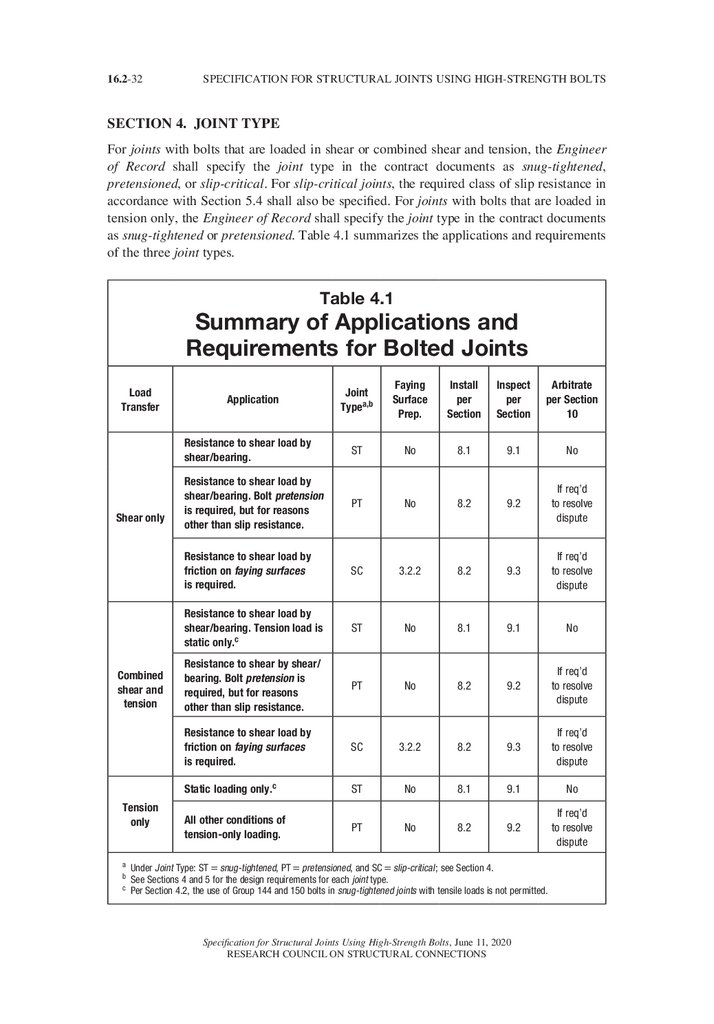
Section 4. Joint Type. . . . . . . . . . . . . . . . . . . . . . . . . . . . . . . . . . . . . . . . . . . . . . . . . . . . 32
4.1. Snug-Tightened Joints . . . . . . . . . . . . . . . . . . . . . . . . . . . . . . . . . . . . . . . . . . . 34
4.2. Pretensioned Joints . . . . . . . . . . . . . . . . . . . . . . . . . . . . . . . . . . . . . . . . . . . . . 35
4.3. Slip-Critical Joints . . . . . . . . . . . . . . . . . . . . . . . . . . . . . . . . . . . . . . . . . . . . . . 35
Section 5. Limit States in Bolted Joints. . . . . . . . . . . . . . . . . . . . . . . . . . . . . . . . . . . . . 37
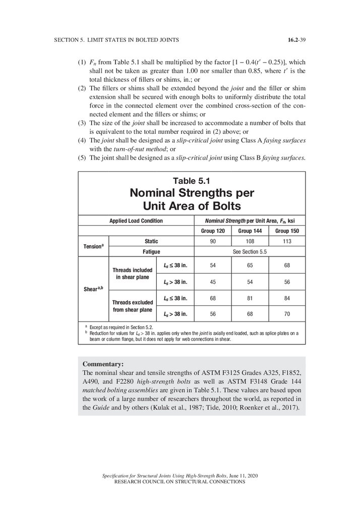
5.1. Nominal Shear and Tensile Strengths . . . . . . . . . . . . . . . . . . . . . . . . . . . . . . . 38
5.2. Combined Shear and Tension . . . . . . . . . . . . . . . . . . . . . . . . . . . . . . . . . . . . . 41
5.3. Nominal Bearing Strength at Bolt Holes . . . . . . . . . . . . . . . . . . . . . . . . . . . . 42
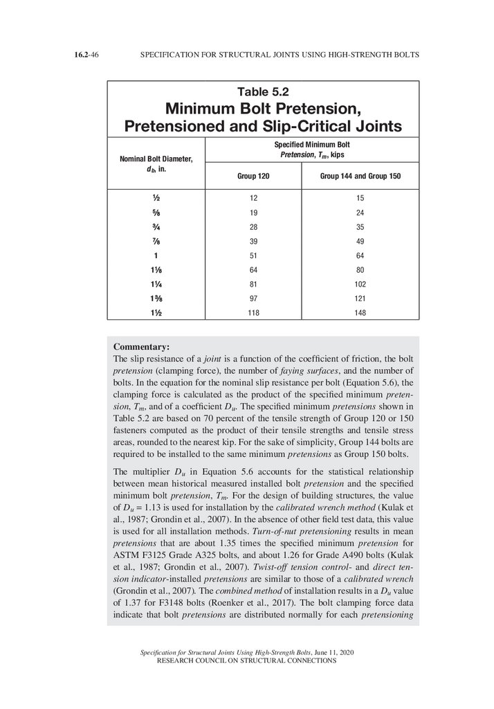
5.4. Design Slip Resistance . . . . . . . . . . . . . . . . . . . . . . . . . . . . . . . . . . . . . . . . . . 44
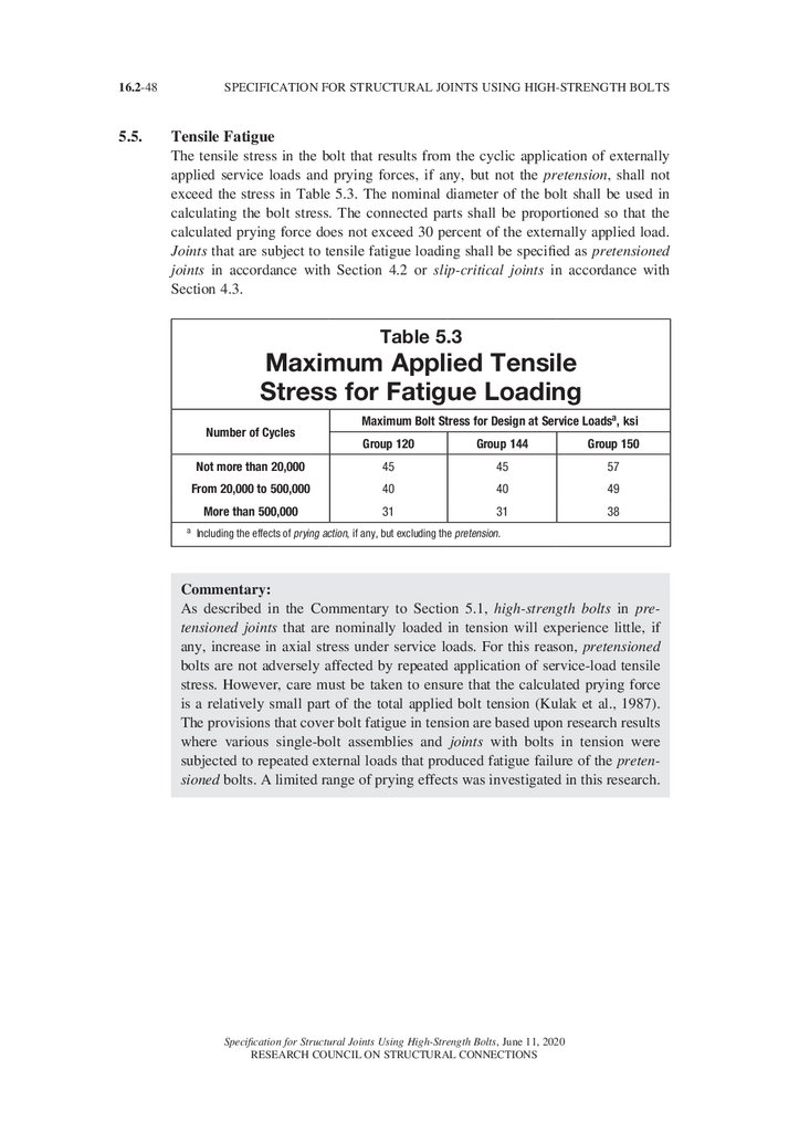
5.5. Tensile Fatigue . . . . . . . . . . . . . . . . . . . . . . . . . . . . . . . . . . . . . . . . . . . . . . . . 48
Specification for Structural Joints Using High-Strength Bolts, June 11, 2020
RESEARCH COUNCIL ON STRUCTURAL CONNECTIONS
9.
TABLE OF CONTENTS16.2-vii
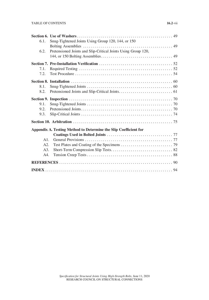
Section 6. Use of Washers. . . . . . . . . . . . . . . . . . . . . . . . . . . . . . . . . . . . . . . . . . . . . . . . 49
6.1. Snug-Tightened Joints Using Group 120, 144, or 150
Bolting Assemblies . . . . . . . . . . . . . . . . . . . . . . . . . . . . . . . . . . . . . . . . . . . . . 49
6.2. Pretensioned Joints and Slip-Critical Joints Using Group 120,
144, or 150 Bolting Assemblies. . . . . . . . . . . . . . . . . . . . . . . . . . . . . . . . . . . . 49
Section 7. Pre-Installation Verification. . . . . . . . . . . . . . . . . . . . . . . . . . . . . . . . . . . . . 52
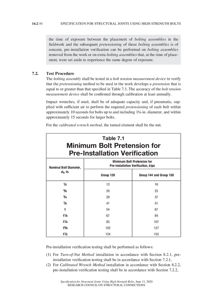
7.1. Required Testing . . . . . . . . . . . . . . . . . . . . . . . . . . . . . . . . . . . . . . . . . . . . . . . 52
7.2. Test Procedure. . . . . . . . . . . . . . . . . . . . . . . . . . . . . . . . . . . . . . . . . . . . . . . . . 54
Section 8. Installation . . . . . . . . . . . . . . . . . . . . . . . . . . . . . . . . . . . . . . . . . . . . . . . . . . . 60
8.1. Snug-Tightened Joints. . . . . . . . . . . . . . . . . . . . . . . . . . . . . . . . . . . . . . . . . . . 60
8.2. Pretensioned Joints and Slip-Critical Joints. . . . . . . . . . . . . . . . . . . . . . . . . . . 61
Section 9. Inspection . . . . . . . . . . . . . . . . . . . . . . . . . . . . . . . . . . . . . . . . . . . . . . . . . . . . . 70
9.1. Snug-Tightened Joints. . . . . . . . . . . . . . . . . . . . . . . . . . . . . . . . . . . . . . . . . . . 70
9.2. Pretensioned Joints. . . . . . . . . . . . . . . . . . . . . . . . . . . . . . . . . . . . . . . . . . . . . . 70
9.3. Slip-Critical Joints. . . . . . . . . . . . . . . . . . . . . . . . . . . . . . . . . . . . . . . . . . . . . . 74
Section 10. Arbitration . . . . . . . . . . . . . . . . . . . . . . . . . . . . . . . . . . . . . . . . . . . . . . . . . . 75
Appendix A. Testing Method to Determine the Slip Coefficient for
Coatings Used in Bolted Joints . . . . . . . . . . . . . . . . . . . . . . . . . . . . . . . . . 77
A1. General Provisions . . . . . . . . . . . . . . . . . . . . . . . . . . . . . . . . . . . . . . . . . . . . 77
A2. Test Plates and Coating of the Specimens. . . . . . . . . . . . . . . . . . . . . . . . . . 79
A3. Short-Term Compression Slip Tests. . . . . . . . . . . . . . . . . . . . . . . . . . . . . . . . 82
A4. Tension Creep Tests. . . . . . . . . . . . . . . . . . . . . . . . . . . . . . . . . . . . . . . . . . . 88
REFERENCES. . . . . . . . . . . . . . . . . . . . . . . . . . . . . . . . . . . . . . . . . . . . . . . . . . . . . . . . . 90
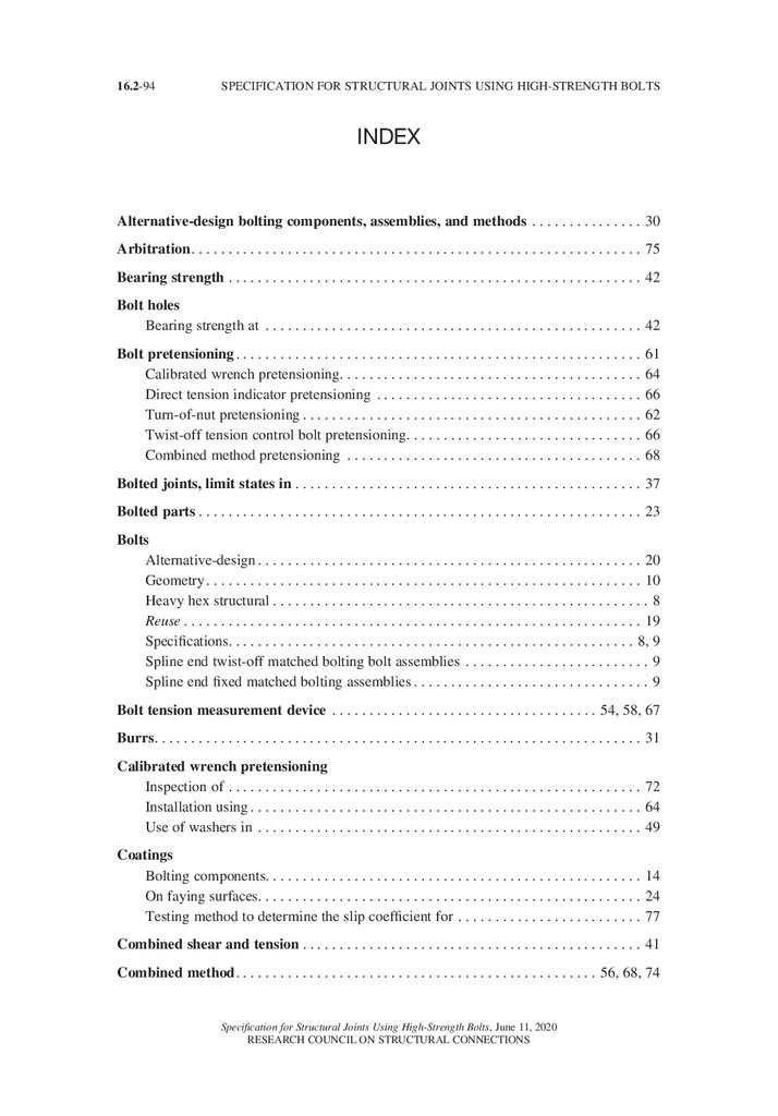
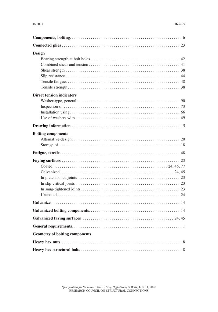
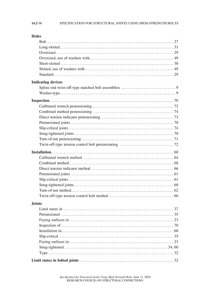
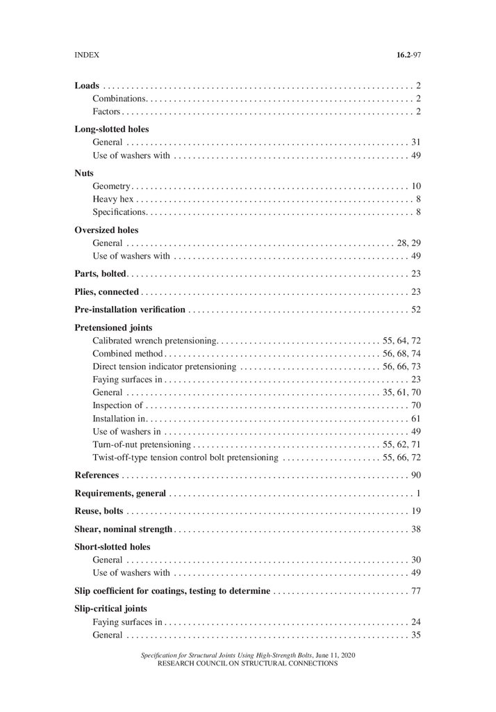
INDEX. . . . . . . . . . . . . . . . . . . . . . . . . . . . . . . . . . . . . . . . . . . . . . . . . . . . . . . . . . . . . . . . 94
Specification for Structural Joints Using High-Strength Bolts, June 11, 2020
RESEARCH COUNCIL ON STRUCTURAL CONNECTIONS
10.
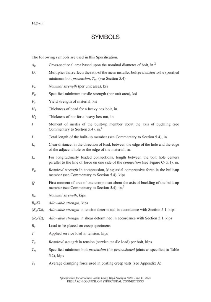
16.2-viiiSYMBOLS
The following symbols are used in this Specification.
Ab
Cross-sectional area based upon the nominal diameter of bolt, in.2
Du
Multiplier that reflects the ratio of the mean installed bolt pretension to the specified
minimum bolt pretension, Tm, (see Section 5.4)
Fn
Nominal strength (per unit area), ksi
Fu
Specified minimum tensile strength (per unit area), ksi
Fy
Yield strength of material, ksi
H1
Thickness of head for a heavy hex bolt, in.
H2
Thickness of nut for a heavy hex nut, in.
I
Moment of inertia of the built-up member about the axis of buckling (see
Commentary to Section 5.4), in.4
L
Total length of the built-up member (see Commentary to Section 5.4), in.
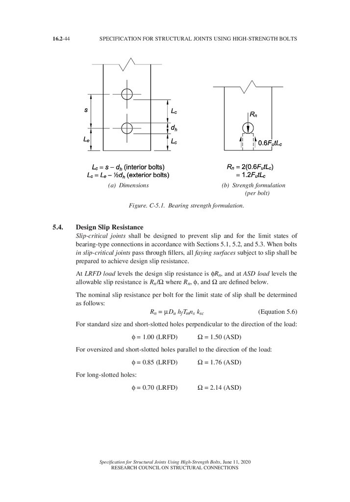
Lc Clear distance, in the direction of load, between the edge of the hole and the edge
of the adjacent hole or the edge of the material, in.
Ls
For longitudinally loaded connections, length between the bolt hole centers
parallel to the line of force on one side of the connection (see Figure C- 5.1), in.
Pu
Required strength in compression, kips; axial compressive force in the built-up
member (see Commentary to Section 5.4), kips
Q
First moment of area of one component about the axis of buckling of the built-up
member (see Commentary to Section 5.4), in.3
Rn
Nominal strength, kips
Rn /Ω
Allowable strength, kips
(Rn /Ω)t
Allowable strength in tension determined in accordance with Section 5.1, kips
(Rn /Ω)v
Allowable strength in shear determined in accordance with Section 5.1, kips
Rs
Load to be placed on creep specimens
T
Applied service load in tension, kips
Ta
Required strength in tension (service tensile load) per bolt, kips
Tm Specified minimum bolt pretension (for pretensioned joints as specified in Table
5.2), kips
Tt
Average clamping force used in coating creep tests (see Appendix A)
Specification for Structural Joints Using High-Strength Bolts, June 11, 2020
RESEARCH COUNCIL ON STRUCTURAL CONNECTIONS
11.
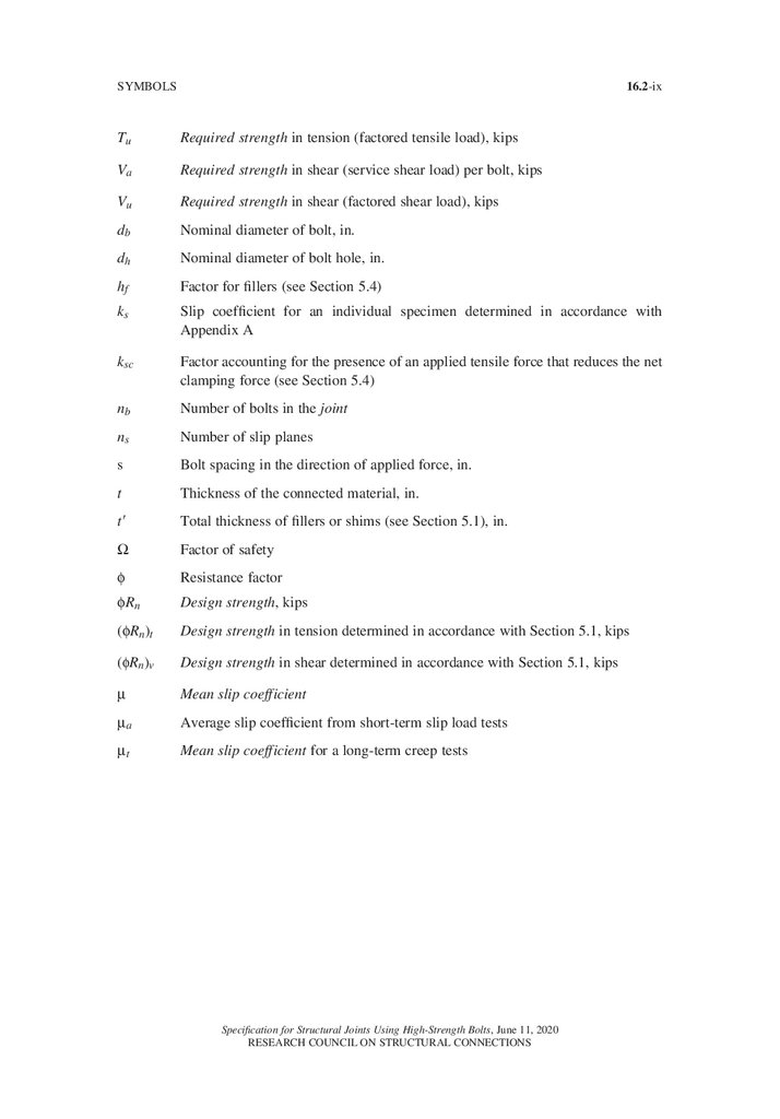
16.2-ixSYMBOLS
Tu
Required strength in tension (factored tensile load), kips
Va
Required strength in shear (service shear load) per bolt, kips
Vu
Required strength in shear (factored shear load), kips
db
Nominal diameter of bolt, in.
dh
Nominal diameter of bolt hole, in.
hf
Factor for fillers (see Section 5.4)
ks
Slip coefficient for an individual specimen determined in accordance with
Appendix A
ksc Factor accounting for the presence of an applied tensile force that reduces the net
clamping force (see Section 5.4)
nb
Number of bolts in the joint
ns
Number of slip planes
s
Bolt spacing in the direction of applied force, in.
t
Thickness of the connected material, in.
t9
Total thickness of fillers or shims (see Section 5.1), in.
W
Factor of safety
f
Resistance factor
fRn
Design strength, kips
(fRn)t
Design strength in tension determined in accordance with Section 5.1, kips
(fRn)v
Design strength in shear determined in accordance with Section 5.1, kips
µ
Mean slip coefficient
µa
Average slip coefficient from short-term slip load tests
µt
Mean slip coefficient for a long-term creep tests
Specification for Structural Joints Using High-Strength Bolts, June 11, 2020
RESEARCH COUNCIL ON STRUCTURAL CONNECTIONS
12.
16.2-xGLOSSARY
The following terms are used in this Specification. Where used, they are italicized to alert
the user that the term is defined in this Glossary.
Allowable Strength. The resistance to be used in ASD design; the nominal strength, Rn ,
divided by the safety factor, Ω.
Arbitration Torque. The torque used for the process of arbitration of disputes of pretensioned bolts (see Section 10).
Available Strength. Design Strength or Allowable Strength, as appropriate.
ASD Load. Load due to a load combination in the applicable building code intended for
allowable strength design (allowable stress design).
Bolt Tension Measurement Device. A calibrated device that is used to verify that the bolting assembly, the pretensioning method, and the tools used are capable to achieve the
required tensions when a pretensioned joint or slip-critical joint is specified.
Bolting Assembly. An assembly of bolting components that is installed as a unit.
Bolting Component. Bolt, nut, washer, direct tension indicator or other element used as a
part of a bolting assembly.
Bolting Material. Rod, flat plate, bar, sheet, or forging subsequently manufactured into a
bolting component.
Calibrated Gap. For verification testing, the average gap, measured to the nearest 0.001 in.,
between a direct tension indicator and the hardened surface on which the protrusion is
bearing when a pretension equal to that in Table 7.1 is applied.
Coated Faying Surface. A faying surface that has been primed, primed and painted, or
protected against corrosion, except by hot-dip galvanizing.
Connection. An assembly of one or more joints that is used to transmit forces between two
or more members.
Cure (noun). A condition of an applied coating in which physical properties such as hardness and slip resistance are achieved.
Cure (verb). The action of changing a coating from the physical properties it had when it
was applied to the physical properties it is expected to have in service.
Degree of Cure. Quantitative measurement or qualitative rating of a physical property, such
as hardness, to determine the development of acceptable intended in-service properties
of an applied coating.
Design Strength. fRn The resistance to be used in LRFD design; the product of the nominal
strength, Rn, and the resistance factor, f.
Specification for Structural Joints Using High-Strength Bolts, June 11, 2020
RESEARCH COUNCIL ON STRUCTURAL CONNECTIONS
13.
16.2-xiGLOSSARY
Direct Tension Indicator. A washer-shaped device incorporating small arch-like protrusions
on the bearing surface that are designed to deform in a controlled manner when subjected
to a compressive load.
Engineer of Record. The party responsible for the design of the structure and for the
approvals that are required in this Specification (see Section 1.6 and the corresponding
Commentary).
Faying Surface. In a connection the contact surface between two connected elements.
Firm Contact. The condition that exists on a faying surface when the plies are solidly seated
against each other, but not necessarily in continuous contact.
Galvanized Faying Surface. A faying surface that has been hot-dip galvanized.
Grip. The total thickness of material a bolt passes through, exclusive of washers or directtension indicators.
Guide. The Guide to Design Criteria for Bolted and Riveted Joints, 2nd Edition (Kulak et
al., 1987).
High-Strength Bolt. An ASTM F3125 or F3148 bolt, or an alternative design bolt that meets
the requirements in Section 2.12.
Initial Tension. Minimum bolt tension attained before application of the required rotation
when using the combined method to pretension bolting assemblies.
Initial Torque. Amount of torque necessary to reach the initial tension in a bolting assembly
pretensioned with the combined method.
Inspector. The party responsible to verify that the contractor has satisfied the provisions of
this Specification in the work.
Job Inspection Gap. A gap between a direct tension indicator and the hardened surface on
which it bears that is less than the gap measured in a bolt tension measurement device
when a tension equal to 1.05 times the minimum required pretension is applied to the
bolting assembly.
Joint. The area of a connection in which one weld or one group of bolting assemblies joins
two or more members or connection elements.
Lot. A quantity of uniquely identified bolting components or assemblies or matched bolting assemblies of the same nominal size and length produced consecutively at the initial
operation from a single mill heat of material and processed at one time, by the same
process, in the same manner, so that statistical sampling is valid.
LRFD Load. Load due to a load combination in the applicable building code intended for
strength design (load and resistance factor design).
Manufacturer. The party that produces one or more bolting components.
Matched Bolting Assembly. Bolting Assembly made of components that are supplied and
tested by the Manufacturer or Supplier in controlled lots as an assembly.
Specification for Structural Joints Using High-Strength Bolts, June 11, 2020
RESEARCH COUNCIL ON STRUCTURAL CONNECTIONS
14.
16.2-xiiSPECIFICATION FOR STRUCTURAL JOINTS USING HIGH-STRENGTH BOLTS
Mean Slip Coefficient. µ, the ratio of the frictional shear load at the faying surface to the
total normal force when slip occurs.
Nominal Strength. The capacity of a structure or component to resist the effects of loads, as
determined by computations using the specified material strengths and dimensions and
equations derived from accepted principles of structural mechanics or by field tests or
laboratory tests of scaled models, allowing for modeling effects and differences between
laboratory and field conditions.
Pretension (noun). A level of tensile force achieved in a bolting assembly through its installation, as required for pretensioned and slip-critical joints.
Pretension (verb). The act of tightening a bolting assembly to a level required for pretensioned and slip-critical joints.
Pretensioned Joint. A joint that transmits shear and/or tensile loads in which the bolts have
been installed in accordance with Section 8.2 to provide a minimum specified pretension
in the installed bolt.
Pretensioning Methods:
Calibrated Wrench Method. Pretensioning technique that relies upon application of an
installation wrench that has been calibrated to provide the required pretension in a
bolting assembly. (Section 8.2.2)
Combined Method. Pretensioning technique that relies upon application of an installation wrench that has been calibrated to provide the initial torque to attain the required
initial tension, followed by the application of the determined relative rotation between
a bolt and nut. (Section 8.2.5)
Direct Tension Indicator Method. Pretensioning technique that relies upon deformation
of the protrusions of a direct tension indicator. (Section 8.2.4)
Turn-of-Nut Method. Pretensioning technique that relies upon application of a designated
amount of relative rotation between bolt and nut. (Section 8.2.1)
Twist-Off Tension Control Bolt Method. Pretensioning technique that relies upon the
application of torque to the nut that causes the removal of the spline by the installation
wrench. (Section 8.2.3)
Protected Storage. Storage of bolting components or bolting assemblies that provides
protection from environmental conditions and contamination that are detrimental to the
installation of components and assemblies.
Prying Action. Lever action that exists in connections in which the line of application of the
applied load is eccentric to the axis of the bolt, causing deformation of the fitting and an
amplification of the axial tension in the bolt.
Required Strength. The load effect acting on an element or connection determined by
structural analysis from the factored loads using the most appropriate critical load
combination.
Reuse. Pretensioning of a bolting assembly that has been previously pretensioned and
subsequently loosened.
Routine Observation. Periodic monitoring of the work in progress.
Specification for Structural Joints Using High-Strength Bolts, June 11, 2020
RESEARCH COUNCIL ON STRUCTURAL CONNECTIONS
15.
16.2-xiiiGLOSSARY
Shear/Bearing Joint. A snug-tightened joint or pretensioned joint with bolts that transmit
shear loads and for which the design criteria are based upon the shear strength of the bolts
and the bearing strength of the connected materials.
Slip-Critical Joint. A joint that transmits shear loads or shear loads in combination with
tensile loads in which the bolting assemblies have been installed in accordance with
Section 8.2 to provide a pretension in the installed bolt (clamping force on the faying
surfaces), and with faying surfaces that have been prepared to provide a calculable resistance against slip.
Snug-Tight Condition. The joint condition in which the plies have been brought into firm
contact and each bolting assembly has at least the tightness attained with either a few
impacts of an impact wrench, resistance to a suitable non-impacting wrench, or the full
effort of an ironworker using an ordinary spud wrench.
Snug-Tightened Joint. A joint in which the bolting assemblies have been installed to the
snug-tight condition.
Spline End Matched Bolting Assemblies:
Fixed. A matched bolting assembly with a spline end that is to remain attached to the bolt
once the installation is complete.
Twist-Off. A matched bolting assembly with a spline end that is to be sheared off by the
installation wrench when using the twist-off tension control bolt method for installation.
Start of Work. Any time prior to the installation of high-strength bolts in structural
connections.
Style. The physical configuration of a high-strength bolt or bolting assembly (heavy hex,
twist-off)
Sufficient Thread Engagement. Having the end of the bolt, not including the spline of a
spline-end bolt, or the available bolt threads extending beyond or at least flush with the
outer face of the nut; a condition that develops the strength of the bolt.
Supplier. The party that sells the bolting components or matched bolting assemblies.
Temporary Bolts. Bolting components or bolting assemblies that are temporarily used in a
joint for purposes such as alignment, fit-up, or shipping.
Touching up. Re-tightening of a bolt loosened by the tightening of adjacent bolts.
Uncoated Faying Surface. A faying surface that has neither been primed, painted, nor
hot-dip galvanized.
Specification for Structural Joints Using High-Strength Bolts, June 11, 2020
RESEARCH COUNCIL ON STRUCTURAL CONNECTIONS
16.
16.2-xivSpecification for Structural Joints Using High-Strength Bolts, June 11, 2020
RESEARCH COUNCIL ON STRUCTURAL CONNECTIONS
17.
SECTION 1. GENERAL REQUIREMENTS16.2-1
SPECIFICATION FOR STRUCTURAL JOINTS
USING HIGH-STRENGTH BOLTS
SECTION 1. GENERAL REQUIREMENTS
1.1.
Scope
This Specification covers the design of bolted joints and the installation and
inspection of bolting components and bolting assemblies listed in Section 1.5.
The Specification also considers the use of alternative-design bolting components,
assemblies, or installation methods as permitted in Section 2.12. This Specification
relates only to those aspects of the connected materials that bear upon the performance of the bolted joints.
The Symbols, Glossary, and Appendix are a part of this Specification. The
Commentary to this Specification that is interspersed throughout is not part of this
Specification.
This Specification shall not be interpreted in a way that prevents the use of bolting components or assemblies and the use of installation methods not specifically
referred to herein, provided that the requirements of Section 2.12 are satisfied.
Commentary:
This Specification covers the design of bolted joints with collateral materials in
the grip that are made of steel. These provisions do not apply when materials
other than steel are included in the grip. These provisions are not applicable to
anchor rods.
Recently, other types of joints that contain low-modulus materials in the grip,
and most notably thermal break joints, have made an entrance in the market and
questions on their use, chiefly for components, such as cladding, awnings, and
roof posts, that are not part of a primary load-resisting system, have come forward. Thermal break joints are not intended for primary load resisting systems.
Several research projects have been conducted (Peterman et al., 2017; Peterman
et al., 2020; Hamel and White, 2016) investigating the structural properties of
thermal break joints showing that the presence within the grip of compressible
gaskets, insulation, or other materials or coatings will preclude the development
and/or retention of the installation pretension in the bolts.
Peterman et al. show that low-modulus materials are permissible in snugtightened joints with bolts subject to shear when long-term loads are limited
to 30% of the low-modulus materials’ ultimate load. Low-modulus materials
that showed acceptable behavior in that study had through-thickness modulus
of elasticity between 400 ksi and 800 ksi and through-thickness compressive
strength between 25 ksi and 65 ksi.
Additionally, with the presence of compressible materials in the grip, the snugtightening operation will not generate a sufficient force in the bolt to deform
the shank so that the head and/or the nut adapt to the slope of the surfaces
under them. Therefore, only surfaces that are near-perpendicular to the bolt axis
should be used in thermal break joints.
Specification for Structural Joints Using High-Strength Bolts, June 11, 2020
RESEARCH COUNCIL ON STRUCTURAL CONNECTIONS
18.
16.2-2SPECIFICATION FOR STRUCTURAL JOINTS USING HIGH-STRENGTH BOLTS
Based on the results in the literature, the Engineer of Record should consider, as
a minimum, the following aspects of a thermal break joint:
• The stiffness and strength of the inserted layers and their influence on the
intended performance of the joint;
• The maximum bolt tension that the layers in the grip can withstand without
losing integrity or performance;
• The installation instructions to prevent overtightening of bolts;
• The effects of the thickness of the added plies on the stiffness and strength of
the bolting assembly and of the connection as a whole;
• The resistance to exposure of the added plies, when applicable;
• The type of forces that the joint is intended to transfer (e.g., shear, shear and
tension, compression, tension without fatigue);
• The long-term behavior of the inserted layers; and
• The electro-chemical interactions of the inserted layers with coatings on steel,
if applicable.
1.2.
Loads, Load Factors, and Load Combinations
The design and construction of the structure shall conform to either an applicable
load and resistance factor design specification for steel structures or to an applicable allowable strength design specification for steel structures. Because factored
load combinations account for the reduced probabilities of maximum loads acting
concurrently, the design strengths given in this Specification shall not be increased.
1.3.
Design for Strength Using Load and Resistance Factor Design (LRFD)
Design according to the provisions for load and resistance factor design (LRFD)
satisfies the requirements of this Specification when the design strength of each
structural component or connection element equals or exceeds the required
strength determined on the basis of the LRFD load combinations.
Design shall be performed in accordance with Equation 1.1:
Ru ≤ φRn
where
Ru = required strength using LRFD load combinations
Rn = nominal strength
φ = resistance factor
φRn = design strength
1.4.
(Equation 1.1)
Design for Strength Using Allowable Strength Design (ASD)
Design according to the provisions for allowable strength design (ASD) satisfies
the requirements of this Specification when the design strength of each structural
component or connection element equals or exceeds the required strength determined on the basis of the ASD load combinations.
Specification for Structural Joints Using High-Strength Bolts, June 11, 2020
RESEARCH COUNCIL ON STRUCTURAL CONNECTIONS
19.
16.2-3SECTION 1. GENERAL REQUIREMENTS
Design shall be performed in accordance with Equation 1.2:
Ra ≤ Rn /Ω
(Equation 1.2)
where
Ra = required strength using ASD load combinations
Rn = nominal strength
Ω
= safety factor
Rn /Ω = allowable strength
Commentary:
This Specification is written in a dual format covering both load and resistance
factor design (LRFD) and allowable strength design (ASD). Both approaches
provide a method of proportioning structural components such that no applicable limit state is exceeded when the structure is subject to all appropriate load
combinations. When a structure or structural component ceases to fulfill the
intended purpose in some way, it is said to have exceeded a limit state. Strength
limit states concern maximum load-carrying capability and are related to safety.
Serviceability limit states are usually related to performance under normal
service conditions and usually are not related to strength or safety. The term
“resistance” includes both strength limit states and serviceability limit states.
Although loads, load factors, and load combinations are not explicitly specified
in this Specification, the safety and resistance factors herein are based upon
the loads, load factors, and load combinations specified in ASCE 7. When the
design is governed by other load criteria, the safety and resistance factors specified herein should be adjusted as appropriate.
1.5.
Referenced Standards and Specifications
The following standards and specifications are referenced herein:
American Institute of Steel Construction
ANSI/AISC 360-16 Specification for Structural Steel Buildings
American Society of Mechanical Engineers
ANSI/ASME B18.2.6-19 Fasteners for Use in Structural Applications
ASTM International
ASTM A123/A123M-17 Standard Specification for Zinc (Hot-Dip Galvanized)
Coatings on Iron and Steel Products
ASTM A194/A194M-20a Standard Specification for Carbon Steel, Alloy Steel,
and Stainless Steel Nuts for Bolts for High Pressure or High Temperature
Service, or Both
ASTM A563-15 Standard Specification for Carbon and Alloy Steel Nuts
ASTM A1059/A1059M-18 Standard Specification for Zinc Alloy ThermoDiffusion Coatings (TDC) on Steel Fasteners, Hardware, and Other Products
ASTM B695-04 (2016) Standard Specification for Coatings of Zinc Mechanically
Deposited on Iron and Steel
Specification for Structural Joints Using High-Strength Bolts, June 11, 2020
RESEARCH COUNCIL ON STRUCTURAL CONNECTIONS
20.
16.2-4SPECIFICATION FOR STRUCTURAL JOINTS USING HIGH-STRENGTH BOLTS
ASTM D3363-20 Standard Test Method for Film Hardness by Pencil Test
ASTM D4752-20 Standard Practice for Measuring MEK Resistance of Ethyl
Silicate (Inorganic) Zinc-Rich Primers by Solvent Rub
ASTM F436/F436M-19 Standard Specification for Hardened Steel Washers, Inch
and Metric Dimensions
ASTM F959/F959M-17a Standard Specification for Compressible-Washer-Type
Direct Tension Indicators for Use with Structural Fasteners, Inch and Metric
Series
ASTM F1136/F1136M-11 (2019) Standard Specification for Zinc/Aluminum Corrosion Protective Coatings for Fasteners
ASTM F2329/F2329M-15 Standard Specification for Zinc Coating, Hot-Dip,
Requirements for Application to Carbon and Alloy Steel Bolts, Screws, Washers,
Nuts, and Special Threaded Fasteners
ASTM F2833-11 (2017) Specification for Corrosion Protective Fastener Coatings
with Zinc Rich Base Coat and Aluminum Organic/Inorganic Type
ASTM F3019/F3019M-19 Standard Specification for Chromium Free Zinc-Flake
Composite, with or without Integral Lubricant, Corrosion Protective Coatings
for Fasteners
ASTM F3125/F3125M-19 Standard Specification for High Strength Structural
Bolts and Assemblies, Steel and Alloy Steel, Heat Treated, Inch Dimensions 120
ksi and 150 ksi Minimum Tensile Strength, and Metric Dimensions 830 MPa and
1040 MPa Minimum Tensile Strength
ASTM F3148-17a Standard Specification for High Strength Structural Bolt
Assemblies, Steel and Alloy Steel, Heat Treated, 144ksi Minimum Tensile
Strength, Inch Dimensions
ASTM F3393-20e1 Standard Specification for Zinc-Flake Coating Systems for
Fasteners
American Society of Civil Engineers
ASCE/SEI 7-16 Minimum Design Loads and Associated Criteria for Buildings and
Other Structures
IFI: Industrial Fastener Institute
IFI 144-2000 (R2013) Test Evaluation Procedures for Coating Qualification
Intended for Use on High-Strength Structural Bolts
SSPC: The Society for Protective Coatings
SSPC-PA2 (11/1/2018) Procedure for Determining Conformance to Dry Coating
Thickness Requirements
Commentary:
Dual-unit standards are cited only by the U.S. Customary standard name in this
specification.
Specification for Structural Joints Using High-Strength Bolts, June 11, 2020
RESEARCH COUNCIL ON STRUCTURAL CONNECTIONS
21.
SECTION 1. GENERAL REQUIREMENTS1.6.
16.2-5
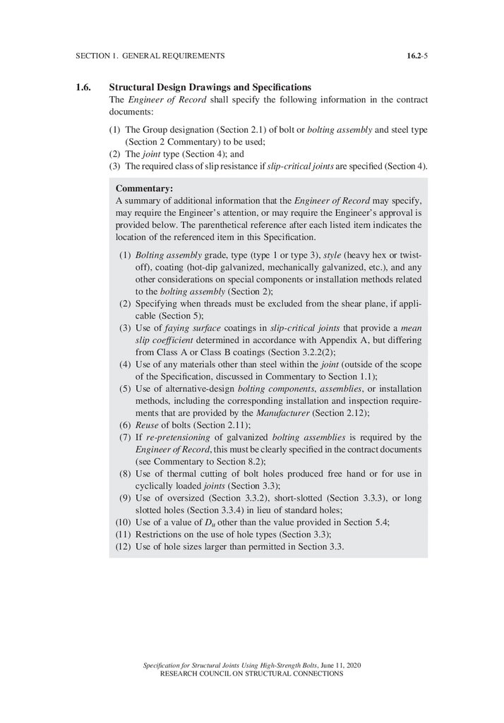
Structural Design Drawings and Specifications
The Engineer of Record shall specify the following information in the contract
documents:
(1) The Group designation (Section 2.1) of bolt or bolting assembly and steel type
(Section 2 Commentary) to be used;
(2) The joint type (Section 4); and
(3) The required class of slip resistance if slip-critical joints are specified (Section 4).
Commentary:
A summary of additional information that the Engineer of Record may specify,
may require the Engineer’s attention, or may require the Engineer’s approval is
provided below. The parenthetical reference after each listed item indicates the
location of the referenced item in this Specification.
(1) Bolting assembly grade, type (type 1 or type 3), style (heavy hex or twistoff), coating (hot-dip galvanized, mechanically galvanized, etc.), and any
other considerations on special components or installation methods related
to the bolting assembly (Section 2);
(2) Specifying when threads must be excluded from the shear plane, if applicable (Section 5);
(3) Use of faying surface coatings in slip-critical joints that provide a mean
slip coefficient determined in accordance with Appendix A, but differing
from Class A or Class B coatings (Section 3.2.2(2);
(4) Use of any materials other than steel within the joint (outside of the scope
of the Specification, discussed in Commentary to Section 1.1);
(5) Use of alternative-design bolting components, assemblies, or installation
methods, including the corresponding installation and inspection requirements that are provided by the Manufacturer (Section 2.12);
(6) Reuse of bolts (Section 2.11);
(7) If re-pretensioning of galvanized bolting assemblies is required by the
Engineer of Record, this must be clearly specified in the contract documents
(see Commentary to Section 8.2);
(8) Use of thermal cutting of bolt holes produced free hand or for use in
cyclically loaded joints (Section 3.3);
(9) Use of oversized (Section 3.3.2), short-slotted (Section 3.3.3), or long
slotted holes (Section 3.3.4) in lieu of standard holes;
(10) Use of a value of Du other than the value provided in Section 5.4;
(11) Restrictions on the use of hole types (Section 3.3);
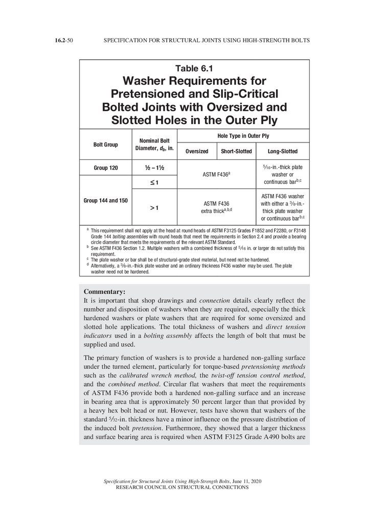
(12) Use of hole sizes larger than permitted in Section 3.3.
Specification for Structural Joints Using High-Strength Bolts, June 11, 2020
RESEARCH COUNCIL ON STRUCTURAL CONNECTIONS
22.
16.2-6SPECIFICATION FOR STRUCTURAL JOINTS USING HIGH-STRENGTH BOLTS
SECTION 2. BOLTING COMPONENTS AND ASSEMBLIES
2.1.
Group Designations
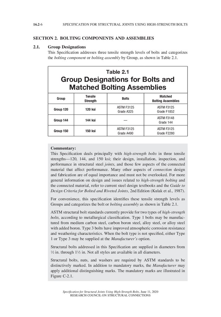
This Specification addresses three tensile strength levels of bolts and categorizes
the bolting component or bolting assembly by Group, as shown in Table 2.1.
Table 2.1
Group Designations for Bolts and
Matched Bolting Assemblies
Group
Tensile
Strength
Bolts
Matched
Bolting Assemblies
Group 120
120 ksi
ASTM F3125
Grade A325
ASTM F3125
Grade F1852
Group 144
144 ksi
—
ASTM F3148
Grade 144
Group 150
150 ksi
ASTM F3125
Grade A490
ASTM F3125
Grade F2280
Commentary:
This Specification deals principally with high-strength bolts in three tensile
strengths—120, 144, and 150 ksi; their design, installation, inspection, and
performance in structural steel joints, and those few aspects of the connected
material that affect performance. Many other aspects of connection design
and fabrication are of equal importance and must not be overlooked. For more
general information on design and issues related to high-strength bolting and
the connected material, refer to current steel design textbooks and the Guide to
Design Criteria for Bolted and Riveted Joints, 2nd Edition (Kulak et al., 1987).
For convenience, this specification identifies these tensile strength levels as
Groups and categorizes the bolt or bolting assembly as shown in Table 2.1.
ASTM structural bolt standards currently provide for two types of high-strength
bolts, according to metallurgical classification. Type 1 bolts may be manufactured from medium carbon steel, carbon boron steel, alloy steel, or alloy steel
with added boron. Type 3 bolts have improved atmospheric corrosion resistance
and weathering characteristics. When the bolt type is not specified, either Type
1 or Type 3 may be supplied at the Manufacturer’s option.
Structural bolts addressed in this Specification are supplied in diameters from
2 in. through 12 in. Not all styles are available in all diameters.
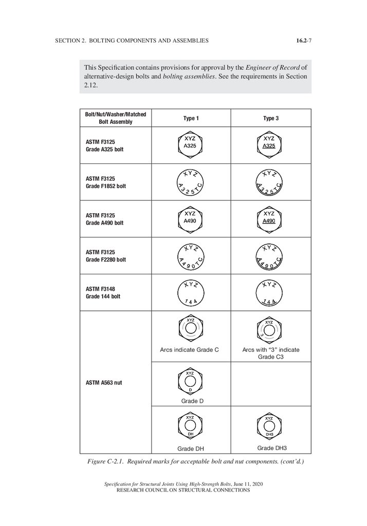
Structural bolts, nuts, and washers are required by ASTM standards to be
distinctively marked. In addition to mandatory marks, the Manufacturer may
apply additional distinguishing marks. The mandatory marks are illustrated in
Figure C-2.1.
Specification for Structural Joints Using High-Strength Bolts, June 11, 2020
RESEARCH COUNCIL ON STRUCTURAL CONNECTIONS
23.
16.2-7SECTION 2. BOLTING COMPONENTS AND ASSEMBLIES
This Specification contains provisions for approval by the Engineer of Record of
alternative-design bolts and bolting assemblies. See the requirements in Section
2.12.
Bolt/Nut/Washer/Matched
Bolt Assembly
Type 1
Type 3
Arcs indicate Grade C
Arcs with “3” indicate
Grade C3
ASTM F3125
Grade A325 bolt
ASTM F3125
Grade F1852 bolt
ASTM F3125
Grade A490 bolt
ASTM F3125
Grade F2280 bolt
ASTM F3148
Grade 144 bolt
ASTM A563 nut
Grade D
Grade DH
Grade DH3
Figure C-2.1. Required marks for acceptable bolt and nut components. (cont’d.)
Specification for Structural Joints Using High-Strength Bolts, June 11, 2020
RESEARCH COUNCIL ON STRUCTURAL CONNECTIONS
24.
16.2-8SPECIFICATION FOR STRUCTURAL JOINTS USING HIGH-STRENGTH BOLTS
ASTM F436 washers
ASTM F959 Direct
Tension Indicators for
Group 120
ASTM F959 Direct
Tension Indicators for
Groups 144 and 150
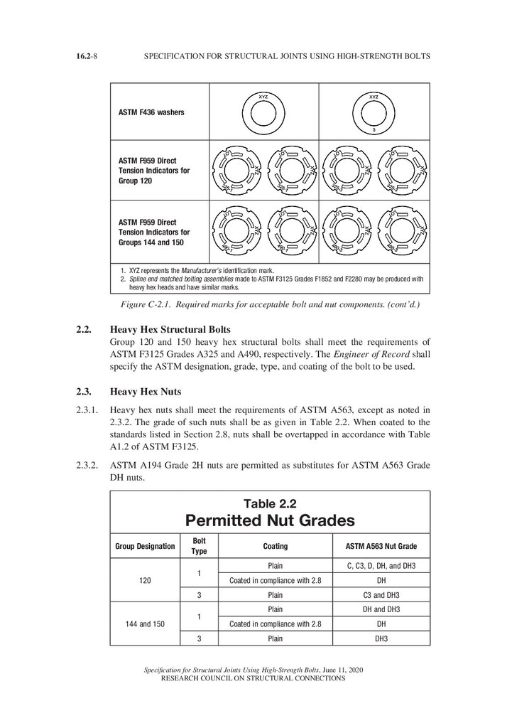
1. XYZ represents the Manufacturer’s identification mark.
2.
Spline end matched bolting assemblies made to ASTM F3125 Grades F1852 and F2280 may be produced with
heavy hex heads and have similar marks.
Figure C-2.1. Required marks for acceptable bolt and nut components. (cont’d.)
2.2.
Heavy Hex Structural Bolts
Group 120 and 150 heavy hex structural bolts shall meet the requirements of
ASTM F3125 Grades A325 and A490, respectively. The Engineer of Record shall
specify the ASTM designation, grade, type, and coating of the bolt to be used.
2.3.
Heavy Hex Nuts
2.3.1.
Heavy hex nuts shall meet the requirements of ASTM A563, except as noted in
2.3.2. The grade of such nuts shall be as given in Table 2.2. When coated to the
standards listed in Section 2.8, nuts shall be overtapped in accordance with Table
A1.2 of ASTM F3125.
2.3.2.
ASTM A194 Grade 2H nuts are permitted as substitutes for ASTM A563 Grade
DH nuts.
Table 2.2
Permitted Nut Grades
Group Designation
120
Bolt
Type
1
3
144 and 150
1
3
Coating
ASTM A563 Nut Grade
Plain
C, C3, D, DH, and DH3
Coated in compliance with 2.8
DH
Plain
C3 and DH3
Plain
DH and DH3
Coated in compliance with 2.8
DH
Plain
DH3
Specification for Structural Joints Using High-Strength Bolts, June 11, 2020
RESEARCH COUNCIL ON STRUCTURAL CONNECTIONS
25.
16.2-9SECTION 2. BOLTING COMPONENTS AND ASSEMBLIES
Commentary:
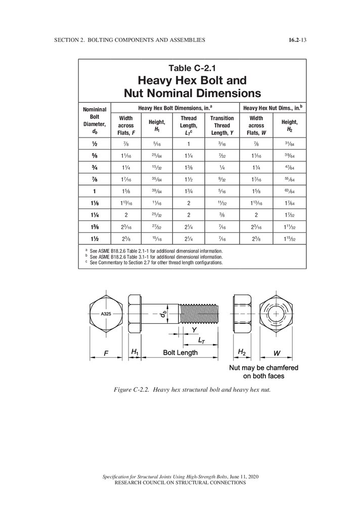
ASTM A563 nuts are manufactured to dimensions as specified in ASME
B18.2.6. The basic dimensions are listed in Table C-2.1 and illustrated in Figure
C-2.2.
Nuts for use with plain Grade 150 bolts are often specified with lubricant to
reduce the effort required to tighten the bolts and to increase their elongation
during installation.
2.4.
Spline End Matched Bolting Assemblies
2.4.1.
Group 120 and 150 spline end twist-off matched bolting assemblies shall meet the
requirements of ASTM F3125 Grade F1852 and Grade F2280, respectively. The
Engineer of Record shall specify the designation, grade, type, and coating of the
matched bolting assembly to be used. See Section 2.8.
Commentary:
ASTM F3125 Grades F1852 and F2280 spline end twist-off matched bolting
assemblies may be manufactured with a round head or a heavy hex head.
2.4.2.
Group 144 spline end fixed matched bolting assemblies shall meet the requirements
of ASTM F3148 Grade 144. The Engineer of Record shall specify the grade, type,
and coating of the matched bolting assembly to be used. See Section 2.8.
2.5.
Washers
Flat circular washers and beveled washers shall meet the requirements of ASTM
F436, except as provided in Table 6.1. The type (Type 1 or Type 3) of such washers
shall be the same as the bolt.
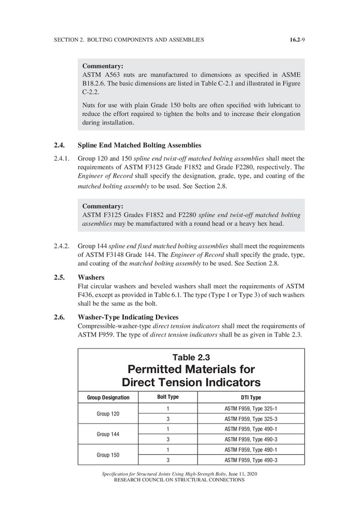
2.6.
Washer-Type Indicating Devices
Compressible-washer-type direct tension indicators shall meet the requirements of
ASTM F959. The type of direct tension indicators shall be as given in Table 2.3.
Table 2.3
Permitted Materials for
Direct Tension Indicators
Group Designation
Group 120
Group 144
Group 150
Bolt Type
DTI Type
1
ASTM F959, Type 325-1
3
ASTM F959, Type 325-3
1
ASTM F959, Type 490-1
3
ASTM F959, Type 490-3
1
ASTM F959, Type 490-1
3
ASTM F959, Type 490-3
Specification for Structural Joints Using High-Strength Bolts, June 11, 2020
RESEARCH COUNCIL ON STRUCTURAL CONNECTIONS
26.
16.2-10SPECIFICATION FOR STRUCTURAL JOINTS USING HIGH-STRENGTH BOLTS
Commentary:
ASTM F959 requires that coatings other than mechanically galvanized zinc and
thermally diffused zinc are to be used only when approved by the Manufacturer.
Because of common installation tension requirements, Group 150 direct tension
indicators are appropriate for installation with Group 144 bolting components.
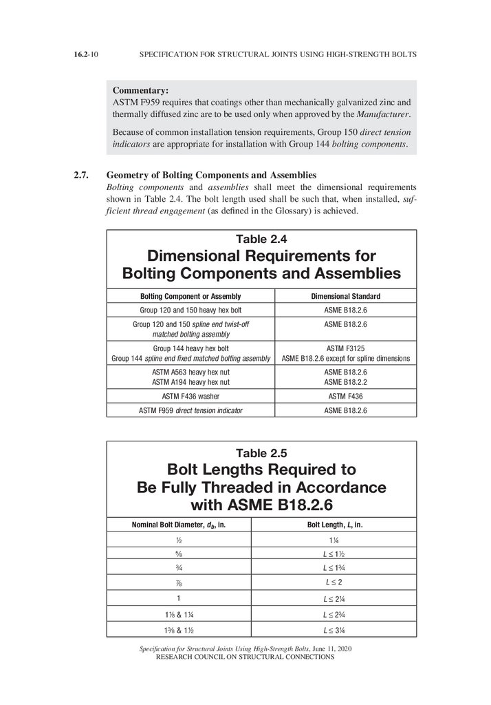
2.7.
Geometry of Bolting Components and Assemblies
Bolting components and assemblies shall meet the dimensional requirements
shown in Table 2.4. The bolt length used shall be such that, when installed, sufficient thread engagement (as defined in the Glossary) is achieved.
Table 2.4
Dimensional Requirements for
Bolting Components and Assemblies
Bolting Component or Assembly
Dimensional Standard
Group 120 and 150 heavy hex bolt
ASME B18.2.6
Group 120 and 150 spline end twist-off
matched bolting assembly
ASME B18.2.6
Group 144 heavy hex bolt
Group 144 spline end fixed matched bolting assembly
ASTM F3125
ASME B18.2.6 except for spline dimensions
ASTM A563 heavy hex nut
ASTM A194 heavy hex nut
ASME B18.2.6
ASME B18.2.2
ASTM F436 washer
ASTM F436
ASTM F959 direct tension indicator
ASME B18.2.6
Table 2.5
Bolt Lengths Required to
Be Fully Threaded in Accordance
with ASME B18.2.6
Nominal Bolt Diameter, db , in.
Bolt Length, L, in.
2
14
s
L ≤ 12
w
L ≤ 1w
d
L≤2
1
L ≤ 24
18 & 14
L ≤ 2w
1a & 12
L ≤ 34
Specification for Structural Joints Using High-Strength Bolts, June 11, 2020
RESEARCH COUNCIL ON STRUCTURAL CONNECTIONS
27.
SECTION 2. BOLTING COMPONENTS AND ASSEMBLIES16.2-11
Commentary:
Structural bolts are manufactured to the dimensions specified in ASME B18.2.6.
The basic dimensions are listed in Table C-2.1 and illustrated in Figure C-2.2.
The principal geometric features of heavy hex structural bolts that distinguish
them from bolts for general applications are the head size and the unthreaded
body length. Heavy hex structural bolt heads have the same width-across-flat
dimensions as heavy hex nuts so that an ironworker may use the same wrench
or socket on either the bolt head or the nut.
With the specific exception of fully threaded bolts and the other permitted variances discussed below, heavy hex structural bolts have shorter threaded lengths
than bolts for general applications. By making the body length of the bolt the
control dimension, it is possible to exclude the bolt threads from all shear planes
when desirable (except in cases of thin plies adjacent to the nut).
The shorter threaded lengths provided with heavy hex structural bolts tend to
minimize the threaded portion of the bolt within the grip. Accordingly, care
must be exercised to provide adequate threaded length between the nut and
the bolt head to enable appropriate installation without jamming the nut on the
thread run-out.
Depending upon the length increments of supplied bolts, for a bolting assembly
without washers, the full thread of a bolt may extend into the grip as far as a
in. for 2-, s-, w-, d-, 14- and 12-in. diameter bolts, and as far as 2 in. for 1,
18, and 1a in. diameter bolts. When the thickness of the ply closest to the nut
is less than these dimensions, it may still be possible to exclude the threads from
the shear plane, when required, depending upon the specific combination of bolt
length, grip, and number of washers used under the nut (Carter, 1996). If necessary, the next increment of bolt length can be specified along with ASTM F436
washers in sufficient quantity to both exclude the threads from the shear plane
and ensure that the bolting assembly can be properly installed with adequate
threads included in the grip.
At maximum accumulation of tolerances from all components in the bolting
assembly, the thread run-out may cross the shear plane for the critical combination of bolt length and grip used to select the foregoing rules of thumb for ply
thickness required to exclude the threads. Previous editions of this Specification
treated shear planes in the thread transition length (see dimension Y in Figure
C-2.2) as if the threads were excluded. Recent evaluation of this transition area
and the variations permitted by ASME B18.2.6 (Swanson et al., 2020a,b) have
caused the more conservative approach taken in this edition. See Section 5.1.
Specification for Structural Joints Using High-Strength Bolts, June 11, 2020
RESEARCH COUNCIL ON STRUCTURAL CONNECTIONS
28.
16.2-12SPECIFICATION FOR STRUCTURAL JOINTS USING HIGH-STRENGTH BOLTS
There are exceptions to the standard thread length requirements for F3125
Grades A325 and A490 bolts, Grades F1852 and 2280 matched bolting assemblies, and F3148 Grade 144 matched bolting assemblies. First, ASME B18.2.6
requires that bolts shorter than certain lengths be fully threaded. (Table 2.5
lists such bolt lengths, which vary by diameter.) However, due to different
Manufacturers’ production methods the threads on such short bolts may not
reach completely to the head and thus may leave the appearance of a usable
shank or full-diameter body. Since any such appearance may differ and its presence cannot be predicted reliably, for certain joints with thin plies where such
short, fully threaded bolts are used, the Engineer of Record should assume that
no usable shank or full-body diameter exists and should assume that in such
joints any shear planes will cross the bolt threads. Additional information on
this approach can be found in Swanson et al. (2020a,b).
Secondly, optional supplementary requirements for ASTM F3125 Grade A325
and F3148 bolts permit the purchaser to specify bolts that are threaded for the
full length of the shank if the nominal length of the bolt is equal to or less than
four times its nominal diameter. This option is provided to increase economy
through simplified ordering and inventory control in the fabrication and erection
of structures. It is particularly useful in those structures in which the strength
of the connection is dependent upon the bearing strength of relatively thin connected material rather than the shear strength of the bolt, whether with threads
in the shear plane or not. ASTM F3125 and ASTM F3148 require that bolts
ordered to such supplementary requirements be marked with the symbol “T”.
Lastly, optional supplementary requirements in ASTM F3125 permit the purchaser to specify threads of any length when necessary. ASTM F3125 requires
that such bolts are to be marked with an “S”. Such special thread lengths are
produced only when specifically ordered.
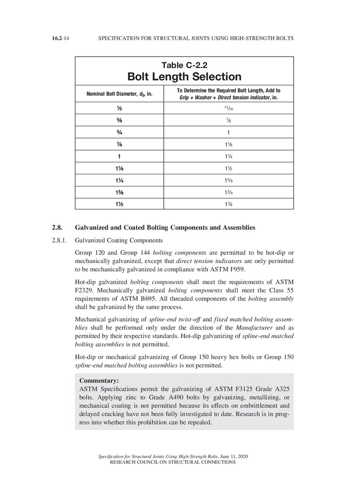
To determine the required bolt length, the value shown in Table C-2.2 should
be added to the grip (i.e., the total thickness of all connected material, exclusive
of washers). For each ASTM F436 washer that is used, add 5/32 in.; for each
beveled washer, add c in. The tabulated values provide for manufacturing
tolerances and sufficient thread engagement with a heavy hex nut. The length
determined by the use of Table C-2.2 should be adjusted to the nearest 4-in.
increment (or 2-in. increment for lengths exceeding 6 in.). A more extensive
table for bolt length selection based upon these rules is available (Carter, 1996;
Swanson et al., 2020a).
Specification for Structural Joints Using High-Strength Bolts, June 11, 2020
RESEARCH COUNCIL ON STRUCTURAL CONNECTIONS
29.
16.2-13SECTION 2. BOLTING COMPONENTS AND ASSEMBLIES
Table C-2.1
Heavy Hex Bolt and
Nut Nominal Dimensions
Heavy Hex Bolt Dimensions, in.a
Heavy Hex Nut Dims., in.b
Nomininal
Bolt
Diameter,
db
Width
across
Flats, F
Height,
H1
Thread
Length,
LT c
Transition
Thread
Length, Y
Width
across
Flats, W
Height,
H2
12
/
78
/
5 16
/
1
3 16
/
78
/
3 1 64
58
/
1 16
1/
25 64
/
14
1/
7 32
/
1 16
1/
3 9 64
34
/
1/
15 32
/
38
1/
14
/
1/
47 64
78
/
7 16
1/
35 64
/
12
1/
9 32
/
7 16
1/
55 64
1
58
1/
39 64
/
34
1/
5 16
/
58
1/
63 64
11/8
113/16
11 16
/
2
11 32
/
113/16
17/64
11/4
2
25 32
/
2
38
/
2
17/32
13/8
2 3/16
27 32
/
21/4
7 16
/
23/16
111/32
11/2
2 3/8
15 16
/
21/4
7 16
/
23/8
115/32
14
14
a See ASME B18.2.6 Table 2.1-1 for additional dimensional information.
b See ASME B18.2.6 Table 3.1-1 for additional dimensional information.
c See Commentary to Section 2.7 for other thread length configurations.
Figure C-2.2. Heavy hex structural bolt and heavy hex nut.
Specification for Structural Joints Using High-Strength Bolts, June 11, 2020
RESEARCH COUNCIL ON STRUCTURAL CONNECTIONS
/
/
/
/
/
30.
16.2-14SPECIFICATION FOR STRUCTURAL JOINTS USING HIGH-STRENGTH BOLTS
Table C-2.2
Bolt Length Selection
Nominal Bolt Diameter, db, in.
To Determine the Required Bolt Length, Add to
Grip + Washer + Direct tension indicator, in.
12
/
11 16
58
/
78
34
/
1
78
/
11/8
1
11/4
11/8
11/2
11/4
15/8
13/8
13/4
11/2
17/8
/
/
2.8.
Galvanized and Coated Bolting Components and Assemblies
2.8.1.
Galvanized Coating Components
Group 120 and Group 144 bolting components are permitted to be hot-dip or
mechanically galvanized, except that direct tension indicators are only permitted
to be mechanically galvanized in compliance with ASTM F959.
Hot-dip galvanized bolting components shall meet the requirements of ASTM
F2329. Mechanically galvanized bolting components shall meet the Class 55
requirements of ASTM B695. All threaded components of the bolting assembly
shall be galvanized by the same process.
Mechanical galvanizing of spline-end twist-off and fixed matched bolting assemblies shall be performed only under the direction of the Manufacturer and as
permitted by their respective standards. Hot-dip galvanizing of spline-end matched
bolting assemblies is not permitted.
Hot-dip or mechanical galvanizing of Group 150 heavy hex bolts or Group 150
spline-end matched bolting assemblies is not permitted.
Commentary:
ASTM Specifications permit the galvanizing of ASTM F3125 Grade A325
bolts. Applying zinc to Grade A490 bolts by galvanizing, metallizing, or
mechanical coating is not permitted because its effects on embrittlement and
delayed cracking have not been fully investigated to date. Research is in progress into whether this prohibition can be repealed.
Specification for Structural Joints Using High-Strength Bolts, June 11, 2020
RESEARCH COUNCIL ON STRUCTURAL CONNECTIONS
31.
SECTION 2. BOLTING COMPONENTS AND ASSEMBLIES16.2-15
Galvanizing or coating bolting components affects the stripping strength of the
bolting assembly. To accommodate the variation in coating thickness on bolt
threads, it is usual practice when coating bolting components to tap the nut
oversize (or “overtap”). This results in a reduction of thread engagement with
a consequent reduction of the stripping strength. It is important that the specified proof load of the nut be higher than the tensile strength of the bolt. Only the
hardened nut grades have adequate strength after overtapping to meet ASTM
structural bolt strength requirements. Therefore, only ASTM A563 Grades DH
and DH3 and ASTM A194 Grade 2H nuts are suitable for use as galvanized nuts.
Galvanized high-strength bolts and nuts must be considered as a matched
bolting assembly, and three principal factors must be considered so that the
provisions of this Specification are understood and properly applied. These are:
(1) The effect of the galvanizing process on the mechanical properties of highstrength bolting materials;
(2) The effect of overtapping galvanized nuts on the nut’s stripping strength;
and
(3) The effect of galvanizing and lubrication on the torque required for pretensioning.
Birkemoe and Herrschaft (1970) showed that, in the as-galvanized condition,
galvanizing increases the friction between the bolt and nut threads as well as
the variability of the torque-induced pretension. A lower required torque and
more consistent results are obtained if the nuts are lubricated. Thus, ASTM
F3125 requires that a galvanized bolt and a galvanized and lubricated nut be
assembled in a steel joint with an equivalently coated washer and tested by the
Supplier prior to shipment. This testing, called rotational capacity (or “rocap”)
testing, must show that the galvanized nut with the lubricant provided may be
rotated from the snug-tight condition well in excess of the rotation required for
pretensioned installation without stripping. This requirement applies to hot-dip
galvanized and mechanically galvanized bolting assemblies. The above requirements clearly indicate that:
(1) Galvanized high-strength bolts and nuts must be treated as a matched bolting assembly; and
(2) The Supplier must supply nuts that have been lubricated and tested with the
supplied bolts.
The purchase of galvanized high-strength bolts and nuts from separate Suppliers
is not in accordance with the intent of ASTM F3125 because the Supplier
responsibility for the performance of the bolting assembly clearly could not have
been provided as required.
Because some of the lubricants used to meet the requirements of ASTM standards are water soluble, it is advisable that galvanized high-strength bolts and
nuts be shipped and stored in sealed metal or plastic containers. Containers of
bolting components with wax-type lubricants should not be subjected to heat
that would cause depletion or change in the properties of the lubricant.
Specification for Structural Joints Using High-Strength Bolts, June 11, 2020
RESEARCH COUNCIL ON STRUCTURAL CONNECTIONS
32.
16.2-16SPECIFICATION FOR STRUCTURAL JOINTS USING HIGH-STRENGTH BOLTS
ASTM F3125 allows for both hot-dip galvanizing (ASTM F2329) and mechanical galvanizing (ASTM B695). The effects of the two coating processes on
the performance characteristics and installation requirements are different. In
accordance with ASTM F3125, all threaded components of the bolting assembly
must be galvanized by the same process. (The Supplier’s option is limited to one
process per item with no mixed processes in a lot.) Mixing high-strength bolts
that are galvanized by one process with nuts that are galvanized by the other
may result in an unworkable bolting assembly.
Steels with tensile strength of 200 ksi and higher are subject to embrittlement
if hydrogen is permitted to remain in the steel and the steel is subjected to high
tensile stress. The minimum tensile strength of ASTM F3125 Grades A325 and
F1852 bolts is 120 ksi, while the minimum for ASTM F3148 bolts is 144 ksi.
Maximum hardness limits result in production tensile strengths well below the
critical range. The minimum tensile strength for ASTM F3125 Grades A490
and F2280 bolts is 150 ksi and in addition, a maximum tensile strength limit of
173 ksi is specified to provide a margin below 200 ksi. The hardness maximum
of 38 HRC for ASTM F3125 Grade A490 bolts provides a safeguard against
hydrogen embrittlement. However, because Manufacturers must target their
production slightly higher than the required minimum, Grades A490 and F2280
bolts close to the critical range of tensile strength must be anticipated. For plain
finish high-strength bolts, this is not a cause for concern. However, if the bolt is
hot-dip galvanized, delayed brittle fracture in service is a concern because of the
possibility of the introduction of hydrogen during the pickling operation of the
hot-dip galvanizing process and the subsequent “sealing-in” of the hydrogen by
the zinc coating. There also exists the possibility of cathodic hydrogen absorption arising from the corrosion process in certain aggressive environments.
2.8.2.
Coated Bolting Components and Assemblies not including Direct Tension Indicators
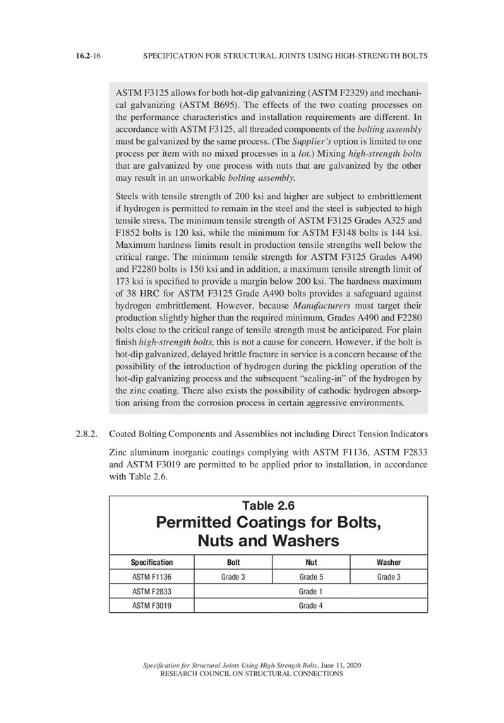
Zinc aluminum inorganic coatings complying with ASTM F1136, ASTM F2833
and ASTM F3019 are permitted to be applied prior to installation, in accordance
with Table 2.6.
Table 2.6
Permitted Coatings for Bolts,
Nuts and Washers
Specification
Bolt
ASTM F1136
Grade 3
Nut
Washer
Grade 5
Grade 3
ASTM F2833
Grade 1
ASTM F3019
Grade 4
Specification for Structural Joints Using High-Strength Bolts, June 11, 2020
RESEARCH COUNCIL ON STRUCTURAL CONNECTIONS
33.
SECTION 2. BOLTING COMPONENTS AND ASSEMBLIES16.2-17
Coating of spline-end twist-off and fixed-matched bolting assemblies shall be
performed only under the direction of the Manufacturer and as permitted by the
assemblies’ respective standards.
When Group 120 and Group 150 bolts are coated to the standards listed in Table
2.6, nuts shall be overtapped in accordance with Table A1.2 of ASTM F3125. For
Group 144 matched bolting assemblies, nuts shall be overtapped in accordance
with Table 1 of ASTM F3148.
The Engineer of Record is permitted to approve other coatings that have been
approved by ASTM for use on bolting components or matched bolting assemblies
between published editions of this Specification.
Commentary
Despite the thin film of the Zn/Al coatings, overtapping the nuts may be
necessary. Similar to mechanical galvanizing, such a process results in a comparatively uniform and evenly distributed coating.
Coated high-strength bolts and nuts must be considered as a matched bolting
assembly, and three principal factors must be considered so that the provisions
of this Specification are understood and properly applied. These are:
(1) The effect of the coating process on the mechanical properties of bolting
materials;
(2) The effect of overtapping coated nuts on the nut’s stripping strength; and
(3) The effect of coating and lubrication on the torque required for pretensioning.
Coatings in Table 2.6 have been tested to indicate they will not degrade the performance of Group 150 bolts due to selected conditions. Inclusion in that table
does not imply any specific corrosion protection performance.
ASTM F3393, Zinc-Flake Coating Systems for Fasteners, was adopted by
ASTM after preparation of this edition of this RCSC Specification. It is a
consolidation and replacement of the three ASTM zinc-flake coating standards
cited in this section (i.e., ASTM F1136, ASTM F2833, and ASTM F3019).
Users of this RCSC Specification should be aware that ASTM F3393, and the
subsequent withdrawal of the three current zinc-flake coating systems currently
listed above, will require additional consideration when such coating systems
are specified.
Investigations in accordance with IFI-144 were completed and presented to the
ASTM F16 Committee on Fasteners (Brahimi, 2006, 2011, 2014, 2017). These
investigations demonstrated that a Zn/Al Inorganic Coating applied in accordance with the relevant standards to ASTM F3125 Grade A490 bolts does not
cause delayed cracking by internal hydrogen embrittlement, nor does it accelerate environmental hydrogen embrittlement by hydrogen absorption. Thus, this
is an acceptable finish to be used on such bolts.
Specification for Structural Joints Using High-Strength Bolts, June 11, 2020
RESEARCH COUNCIL ON STRUCTURAL CONNECTIONS
34.
16.2-18SPECIFICATION FOR STRUCTURAL JOINTS USING HIGH-STRENGTH BOLTS
Although these bolts are typically not used in this manner, the Engineer of
Record should address the embedding of bolts in concrete if the bolts have
coatings containing aluminum. The alkalinity of wet and freshly hardened concrete (less than 7 days old) reacts with free aluminum leading to evolution of
hydrogen gas that consumes the aluminum and can lead to “wormholes” in the
concrete. No research has been performed to date to determine if the aluminum
bound within the coatings is susceptible to this reaction.
2.8.3.
Galvanized or Coated Direct Tension Indicators
Direct tension indicators are permitted to be mechanically galvanized in accordance with ASTM B695 Class 55 or thermo-diffusion coated in accordance with
ASTM A1059. Other coatings compatible with threaded components used in the
work are permitted with the approval of the DTI Manufacturer.
Commentary:
ASTM F959 requires that coatings other than mechanically galvanized zinc and
thermally diffused zinc shall be used only when approved by the direct tension
indicator Manufacturer.
2.9.
Test Reports
Test reports documenting conformance to the applicable specifications for all bolting components and matched bolting assemblies shall be available to the Engineer
of Record and Inspector prior to assembly or erection of structural steel.
Commentary:
Test reports provided by the Manufacturer or Supplier of bolting components
and matched bolting assemblies are required to verify that the components are
identifiable and meet the requirements of the applicable ASTM standard or appropriate consensus standard.
2.10.
Storage and Lubrication
2.10.1. Once received at the installation site, bolting components and bolting assemblies
shall be kept in protected storage.
2.10.2. Only as many bolting components and bolting assemblies as are anticipated to be
installed during the work shift shall be taken from protected storage.
2.10.3. Bolting components and bolting assemblies that are not incorporated into the work
shall be returned to protected storage at the end of the work shift.
2.10.4. Bolting components (including some bolting assemblies) may be field lubricated to
help with installation as deemed practical or necessary, except that the following
matched bolting assemblies shall not be relubricated by anyone other than the
Manufacturer:
Specification for Structural Joints Using High-Strength Bolts, June 11, 2020
RESEARCH COUNCIL ON STRUCTURAL CONNECTIONS
35.
SECTION 2. BOLTING COMPONENTS AND ASSEMBLIES16.2-19
(1) Spline end twist-off matched bolting assemblies;
(2)
Matched bolting assemblies when using the combined method and ASTM
F3148 Grade 144 spline end fixed matched bolting assemblies; and
(3) Alternative-design bolting components or matched bolting assemblies (see
Section 2.12).
2.10.5. Heavy hex head bolting components for snug-tightened joints that accumulate
rust or dirt shall not be incorporated into the work unless they are cleaned and
lubricated, if necessary.
2.10.6. Bolting components and bolting assemblies intended for pretensioned or slipcritical joints that accumulate rust or dirt shall not be incorporated into the work
unless they are cleaned and lubricated, if necessary, and then retested as specified
in Section 7. See Section 2.10.4 for prohibitions on relubrication.
2.10.7. Temporary bolts shall be exempt from this Section’s storage requirements.
Commentary:
Protected storage requirements are specified for high-strength bolts, nuts,
washers, and other bolting components so that the components’ as-manufactured
conditions are maintained as nearly as possible until they are incorporated in
the work.
Because Manufacturers may apply various coatings and lubricants to prevent
corrosion or to facilitate manufacture or installation, the condition of supplied
bolting components and bolting assemblies should not be altered.
If bolting components or bolting assemblies become dirty, rusty, or otherwise
have their as-received condition altered, they may be unsuitable for pretensioned installation. It is also possible that a bolting assembly may not pass the
pre-installation verification requirements of Section 7. Some components can be
cleaned and lubricated by the fabricator or the erector. Because the acceptability
of their installation is dependent upon specific lubrication, the following may be
lubricated only by the Manufacturer:
(1) Spline end twist-off matched bolting assemblies,
(2) Spline end fixed matched bolting assemblies,
(3) Heavy hex bolting assemblies sold as matched bolting assemblies to be
installed using the combined method, and
(4) Some alternative-design bolts and bolting assemblies as specified in the
relevant consensus standard.
2.11.
Reuse
2.11.1. Plain finish Group 120 heavy hex bolts may be reused (1) in snug-tightened joints
without Engineer of Record approval and (2) in pretensioned joints and slip-critical
joints with Engineer of Record approval.
2.11.2. Galvanized or coated bolts of any Group or grade, galvanized or coated spline end
bolting assemblies of any Group or grade, and Group 150 heavy hex bolts shall not
be reused.
Specification for Structural Joints Using High-Strength Bolts, June 11, 2020
RESEARCH COUNCIL ON STRUCTURAL CONNECTIONS
36.
16.2-20SPECIFICATION FOR STRUCTURAL JOINTS USING HIGH-STRENGTH BOLTS
2.11.3. Touching up shall not be considered a reuse.
Commentary:
Pretensioned installation involves the inelastic elongation of the portion of the
threaded length between the nut and the thread run-out. Plain finish ASTM
F3125 Grade A325 and F1852 bolts possess sufficient ductility to undergo more
than one pretensioned installation as suggested in the Guide (Kulak et al., 1987).
As a simple rule of thumb, a plain finish Grade A325 bolt is suitable for reuse
if the nut can be run all the way up the threads by hand.
On the other hand, while ASTM F3125 Grade A490 and F2280 bolts possess sufficient ductility to undergo one pretensioned installation, they are not
consistently ductile enough to undergo a second pretensioned installation. The
Guide also indicates that the coating on galvanized Grade A325 and F1852 bolts
reduces their nut rotation capacity and are thus not to be reused. For additional
guidance see Bowman and Betancourt (1991).
2.12.
Alternative-Design Bolting Components, Assemblies, and Methods
The Specification allows for innovation in bolting components and assemblies in
joints that transmit forces through shear, tension, combined tension and shear, or
friction on faying surfaces and that meet the requirements in this Section. Other
mechanical fasteners are not covered in this Specification. The provisions in this
Specification that are not explicitly covered by the relevant consensus standard of
an alternative-design bolting component or assembly shall still apply.
2.12.1. When approved by the Engineer of Record, alternative-design bolting components,
assemblies, or installation methods are permitted to replace or supplement bolting
components, assemblies, or installation methods described elsewhere in this
Specification under the following conditions:
(1)
Bolting components or assemblies shall meet the minimum manufacturing,
material, and mechanical properties of the grade and type being substituted;
(2)
When used in pretensioned or slip-critical joints, the alternative-design
product or method must meet minimum pretension requirements set in Table
5.2 for the Group being substituted; and
(3) When required by a product or consensus standard or the installation method,
the alternative-design bolting components shall be supplied and used in the
work as a matched bolting assembly.
2.12.2. When approved by the Engineer of Record, the use of consensus standards that are
not referenced in Section 2 is permitted, under the following conditions:
(1) Alternative design bolting components or assemblies must meet the minimum
manufacturing, material, and mechanical properties of an approved consensus
standard;
Specification for Structural Joints Using High-Strength Bolts, June 11, 2020
RESEARCH COUNCIL ON STRUCTURAL CONNECTIONS
37.
SECTION 2. BOLTING COMPONENTS AND ASSEMBLIES16.2-21
(2) When considering strength levels other than those provided in this Specification,
the consensus standard or Manufacturer shall provide, or the Engineer of
Record shall determine, the minimum (and maximum, when applicable) specified values for at least:
a. Proof load and tensile strength;
b. Nominal strength values for Table 5.1;
c. Minimum pretension values for Table 5.2, as required;
d. Fatigue strength values for Table 5.3, as required.
In addition, the consensus standard or Manufacturer shall provide:
e. Washer requirements, as required or if different than Section 6; and
f. Pre-installation verification test, installation, and inspection requirements, if
applicable.
(3) When required by a consensus standard or the installation method, the bolting components shall be supplied and used in the work as a matched bolting
assembly.
2.12.3. Alternative coatings shall meet the performance criteria as specified in the alternative
coating standard and shall not have a detrimental effect on the bolting components
or assemblies, specifically in conformance to Sections 2.12.1(1) and (2).
2.12.4. Alternative-design bolting components or assemblies are permitted to differ in
dimensions from those specified in Section 2 with the following limitations:
(1) Bolts shall have a body diameter and bearing area under the head equal to or
greater than that provided by an equivalent bolt in Section 2.7;
(2) Bolt thread lengths that differ from those in Section 2.7 shall be clearly identified and communicated to the Engineer of Record; and
(3) Nuts and washers shall have a bearing area that is equal to or greater than
that provided by a nut or washer of the same nominal dimensions specified in
Section 2.7, as applicable.
2.12.5. Installation methods shall be provided in the relevant consensus standard or by the
Manufacturer and shall be approved by the Engineer of Record. These instructions
shall provide, as a minimum:
(1) For pretensioned and slip-critical joints, the procedure and frequency of
pre-installation verification;
(2) The alignment of bolt holes to permit insertion of the bolt without undue
damage to the threads;
(3) The placement of bolting assemblies in all types and sizes of holes, including
placement and orientation of the alternative design devices (and ASTM F436/
436M washers, if any);
(4) The systematic assembly of the joint to the snug-tight condition, progressing from the most rigid part of the joint until the connected plies are in firm
contact; and
(5) For pretensioned and slip-critical joints, the subsequent systematic pretensioning of all bolting assemblies in the joint, progressing from the most rigid part of
the joint in a manner that will minimize relaxation of previously pretensioned
bolts.
Specification for Structural Joints Using High-Strength Bolts, June 11, 2020
RESEARCH COUNCIL ON STRUCTURAL CONNECTIONS
38.
16.2-22SPECIFICATION FOR STRUCTURAL JOINTS USING HIGH-STRENGTH BOLTS
2.12.6. Inspection instructions shall be provided in the relevant consensus standard or
by the Manufacturer and shall be approved by the Engineer of Record. These
instructions shall provide, as a minimum:
(1) Required observation of the pre-installation verification testing, when performed; and
(2) Subsequent routine observation to verify the proper use of the alternativedesign product or method.
Commentary:
RCSC’s policy has been to recognize only bolting components and matched
bolting assemblies that meet approved ASTM standards. Other consensus standards that could be considered by the Engineer of Record include EN, JIS, and
ISO standards. However, alternate products, standards, and installation methods
(known collectively as “alternative-designs”) may be used when approved by
the Engineer of Record. Alternative-designs fall into two categories:
(1) Product made as an alternative-design to an ASTM standard referenced in
this document and installed using RCSC installation methods or an alternate
installation method. See Section 2.12.1.
(2) Product made to an ASTM standard that is not referenced in this document
or made to another consensus standard and installed using RCSC installation methods or an alternate installation method. See Section 2.12.2.
When using alternative-designs it is important that the strength of the component and geometry be fully considered so that the requirements of joint design
are met as intended by this Specification. Particularly important are strength
requirements, such as tensile strength, shear strength, and minimum pretension,
along with certain dimensional characteristics vital to proper joint loading, such
as bearing area and bolt body diameter.
Alternative-design provisions are intended to provide flexibility to address
unique needs and design challenges and to enable the use of alternate technology, standards, and practices. This includes products or technology the Council
may not have had the time or opportunity to fully consider, or products with a
frequency of use that might not compel the Council to detail such use in this
document.
Specification for Structural Joints Using High-Strength Bolts, June 11, 2020
RESEARCH COUNCIL ON STRUCTURAL CONNECTIONS
39.
SECTION 3. BOLTED PARTS16.2-23
SECTION 3. BOLTED PARTS
3.1.
Connected Plies
Unless otherwise approved by the Engineer of Record, all connected plies in a joint
that are within the grip of the bolt and any materials that are used under the bolt
head or nut shall be steel with faying surfaces that are uncoated, coated, or galvanized as defined in Section 3.2.
The slope of the surfaces of parts in contact with the bolt head and nut shall be
equal to or less than 1:20 with respect to a plane that is normal to the bolt axis.
Commentary:
The presence of gaskets, insulation, or any compressible materials other than
the specified coatings within the grip will preclude the development and/
or retention of the installed pretensions in the bolts, when required. See the
Commentary to Section 1.1.
Structural bolting assemblies are generally ductile enough to deform to a surface
with a slope that is less than or equal to 1:20 with respect to a plane normal to
the bolt axis when pretensioned. Greater slopes are undesirable because the
resultant localized bending decreases both the strength and the ductility of the
bolt.
3.2.
Faying Surfaces
Faying surfaces and surfaces adjacent to the bolt head and nut shall be free of dirt
and other foreign material.
3.2.1.
Snug-Tightened Joints and Pretensioned Joints: The faying surfaces of snugtightened joints and pretensioned joints as defined in Sections 4.1 and 4.2 are
permitted to be uncoated, coated with coatings of any formulation, or galvanized.
Commentary:
In both snug-tightened joints and pretensioned joints, the ultimate strength is
dependent upon shear transmitted by the bolts and bearing of the bolts against
the connected material. It is independent of any frictional resistance that may
exist on the faying surfaces. Consequently, since slip resistance is not an issue,
the faying surfaces are permitted to be uncoated, coated, or galvanized without
regard to the resulting slip coefficient obtained.
For pretensioned joints, caution should be used in the specification and application of thick coatings within the faying surface, and on ply surfaces under the
bolt head, and under the nut or washer. Although slip resistance is not required,
bolting assemblies in joints with thick or multi-layer coatings may exhibit
significant loss of pretension because of compressive creep in softer coatings
such as epoxies, alkyds, vinyls, acrylics, and urethanes. Previous bolt relaxation
studies have been conducted using uncoated steel with plain finish bolts or
galvanized steel with galvanized bolts. Galvanized faying surfaces ranged up
to approximately 4 mils of thickness, of which approximately half the thickness
Specification for Structural Joints Using High-Strength Bolts, June 11, 2020
RESEARCH COUNCIL ON STRUCTURAL CONNECTIONS
40.
16.2-24SPECIFICATION FOR STRUCTURAL JOINTS USING HIGH-STRENGTH BOLTS
was the compressible soft pure zinc surface layer. The underlying zinc-iron layers are very hard and would exhibit little creep. See Guide, Section 4.4. Tests
have indicated that significant bolt pretension may be lost when the total coating
thickness within the joint approaches 15 mils per surface and that soft surface
coatings beneath the bolt head and nut can contribute to additional reduction in
pretension.
3.2.2.
Slip-Critical Joints: The faying surfaces of slip-critical joints, including those of
filler plates and finger shims, shall meet the following requirements:
(1) Uncoated Faying Surfaces: Uncoated faying surfaces (a) shall be free of scale
(except tight mill scale), coatings, and overspray (i) in areas closer than one
bolt diameter but not less than 1 in. from the edge of any hole, and (ii) in all
areas within the bolt pattern, or (b) shall be blast cleaned prior to assembly.
(2) Coated Faying Surfaces: Coated faying surfaces shall first be blast cleaned
and subsequently coated with a coating that is qualified in accordance with
Appendix A as a Class A or Class B coating (as defined in Section 5.4).
Alternatively, when approved by the Engineer of Record, coatings that provide
a mean slip coefficient that differs from Class A or Class B are permitted when:
(i) The mean slip coefficient m is established by testing in accordance with the
requirements in Appendix A; and
(ii) The design slip resistance is determined in accordance with Section 5.4
using this coefficient, except that, for design purposes, a value of µ greater
than 0.50 shall not be used.
The plies of slip-critical joints with coated faying surfaces shall not be assembled
before the coating has fully cured and in no case before the minimum time that was
used in the qualifying tests or provided in the coating manufacturer’s application
instructions.
On members coated with non-qualified coatings, the faying surfaces shall be free
of coating and overspray (1) in areas closer than one bolt diameter but not less than
1 in. from the edge of any hole, and (2) in all areas within the bolt pattern. See
Figure C-3.1.
(3) Galvanized Faying Surfaces: Galvanized faying surfaces shall be hot-dip galvanized in accordance with the requirements of ASTM A123. Power or hand
wire brushing is not permitted. Galvanized faying surfaces are designated as
Class A for design.
Commentary:
Slip-critical joints are those joints that have specified faying surface conditions
that, in the presence of the clamping force provided by pretensioned bolting
assemblies, resist a design load solely by friction and without displacement at
the faying surfaces. Consequently, it is necessary to prepare the faying surfaces
in a manner such that the desired slip performance is achieved.
Specification for Structural Joints Using High-Strength Bolts, June 11, 2020
RESEARCH COUNCIL ON STRUCTURAL CONNECTIONS
41.
SECTION 3. BOLTED PARTS16.2-25
Clean mill scale steel surfaces (Class A, see Section 5.4) and blast-cleaned steel
surfaces (Class B, see Section 5.4) can be used within slip-critical joints. When
used, it is necessary to keep the faying surfaces free of coatings, including inadvertent overspray.
Corrosion often occurs on uncoated blast-cleaned steel faying surfaces (Class B,
see Section 5.4) due to exposure between the time of fabrication and subsequent
erection. In normal atmospheric exposures, this corrosion is not detrimental and
may actually increase the slip resistance of the joint. Yura et al. (1981) found
that the Class B slip coefficient could be maintained for up to one year prior to
joint assembly.
Polyzois and Frank (1986) demonstrated that, for plate material with thickness
in the range of a in. to w in., the contact pressure caused by bolt pretension
is concentrated on the faying surfaces in annular rings around and close to the
bolts. In this study, unqualified paint on the faying surfaces away from the
edge of the bolt hole by at least one bolt diameter but not less than 1 in. did
not reduce the slip resistance. However, this would not likely be the case for
joints involving thicker material, particularly those with a large number of bolts
on multiple gage lines; the minimum bolt pretension in Table 5.2 might not be
adequate to completely flatten and pull thicker material into tight contact around
every bolt. Instead, the bolt pretension would be balanced by contact pressure
on the regions of the faying surfaces that are in contact. To account for both
possibilities, it is required in this Specification that for unqualified coatings all
areas between the bolts be free of coatings, including overspray, as illustrated
in Figure C-3.1.
As a practical matter, the smaller coating-free area can be laid out and protected
more easily using masking located relative to the bolt-hole pattern than relative to the limits of the complete area of faying surface contact with varying
and uncertain edge distance. Furthermore, the narrow coating strip around
the perimeter of the faying surface minimizes the required field touch-up of
uncoated material outside of the joint.
Polyzois and Frank (1986) also investigated the effect of various degrees of
inadvertent overspray on slip resistance. It was found that even a small amount
of overspray of unqualified paint (that is, not qualified as a Class A or Class B
coating) within the specified coating-free area on clean mill scale can reduce
the slip resistance significantly. On blast-cleaned surfaces, however, the presence of a small amount of overspray was not as detrimental. For simplicity,
this Specification requires that all overspray be prohibited from areas that are
required to be free of coatings in slip-critical joints regardless of whether the
surface is clean mill scale steel or blast-cleaned steel.
Specification for Structural Joints Using High-Strength Bolts, June 11, 2020
RESEARCH COUNCIL ON STRUCTURAL CONNECTIONS
42.
16.2-26SPECIFICATION FOR STRUCTURAL JOINTS USING HIGH-STRENGTH BOLTS
Figure C-3.1. Areas of faying surfaces of slip-critical joints to remain
uncoated with unqualified coatings (db = bolt diameter).
When the faying surfaces of a slip-critical joint are to be protected against
corrosion, a qualified coating must be used. A qualified coating is one that has
been tested in accordance with Appendix A, the sole basis for qualification of
any coating to be used in conjunction with this Specification. Coatings can be
qualified as follows:
(1) As a Class A coating as defined in Section 5.4;
(2) As a Class B coating as defined in Section 5.4; or
(3) As a coating with a mean slip coefficient µ of at least 0.30 (Class A) but not
greater than 0.50 (Class B).
Retesting is required if any essential variable associated with cure, coating composition, or method of manufacture is changed. See Appendix A.
For slip-critical joints, coating testing as prescribed in Appendix A includes
creep tests, which incorporate relaxation in the bolting assembly and the effect
of the coating itself. Specifiers should verify the coating thicknesses used in the
Appendix A testing and verify that the actual maximum average coating thickness is at least 2 mm less than the coating thickness tested. See Appendix A and
Section A1.2.2.
Specification for Structural Joints Using High-Strength Bolts, June 11, 2020
RESEARCH COUNCIL ON STRUCTURAL CONNECTIONS
43.
SECTION 3. BOLTED PARTS16.2-27
Frank and Yura (1981) also investigated the effect of varying the time between
coating the faying surfaces and assembly of the joint and pretensioning the bolts
in order to ascertain if partially cured paint continued to cure within the assembled joint over a period of time. The results indicated that all curing effectively
ceased at the time the joint was assembled and paint that was not fully cured at
that time acted as a lubricant. The slip resistance of a joint that was assembled
after a time less than the curing time used in the qualifying tests was severely
reduced. Thus, the degree of cure prior to mating the faying surfaces is an essential parameter to be specified and controlled during construction.
Prior versions of this Specification included a requirement to hand wire-brush
galvanized surfaces in slip-critical joints, but recent research in combination
with current galvanizing practices has revealed that such brushing does not
improve slip resistance capacity and may reduce it (Donahue et al., 2014).
Field experience and test results have indicated that galvanized assemblies may
continue to slip under sustained loading (Kulak et al., 1987). Tests of hot-dip
galvanized joints subjected to sustained loading show a creep-type behavior
that was not observed in short-duration or fatigue-type load application. See
Appendix A and Commentary to A4.2.
3.3.
Bolt Holes
The nominal dimensions of standard, oversized, short-slotted, and long-slotted
holes for high-strength bolts shall be equal to or less than those shown in Table 3.1.
Holes detailed larger than those shown in Table 3.1 are permitted when specified
or approved by the Engineer of Record. When complete connection design is not
shown in the structural design drawings, the Engineer of Record shall be notified
of the type and dimensions of holes to be used. Oversized holes, short slots not
perpendicular to the applied load, and long slots in any direction shall be subject
to approval by the Engineer of Record. Any restrictions on the use of hole types
permitted in this section shall be specified in the design documents.
Thermally cut holes produced by mechanically guided means are permitted in statically loaded joints. The surface roughness profile of the hole shall not exceed 1,000
microinches as defined in ASME B46.1. Occasional gouges not more than z in. in
depth are permitted. Thermally cut holes produced free hand shall be permitted in
statically loaded joints upon approval by the Engineer of Record.
For cyclically loaded slip-critical joints, mechanically guided thermally cut holes
shall be permitted. For other cyclically loaded joints, thermally cut holes shall be
permitted upon approval by the Engineer of Record.
Specification for Structural Joints Using High-Strength Bolts, June 11, 2020
RESEARCH COUNCIL ON STRUCTURAL CONNECTIONS
44.
16.2-28SPECIFICATION FOR STRUCTURAL JOINTS USING HIGH-STRENGTH BOLTS
Table 3.1
Nominal Bolt Hole Dimensions
Nominal Bolt Hole Dimensionsa,b, in.
Nominal Bolt
Diameter,
d b, in.
Standard
(diameter)
Oversized
(diameter)
12
/
9 16
/
58
/
9 16
58
/
11 16
/
13 16
/
11 16
34
/
13 16
/
15 16
/
78
/
15 16
/
11/16
1
11/8
≥ 11/8
db + 1/8
Short-Slotted
(width × length)
Long-Slotted
(width × length)
/ × 11/16
9 16
/ × 11/4
/ × 7/8
11 16
13 16
/ ×1
13 16
15 16
/ × 11/8
15 16
11/4
11/8 × 15/16
11/8 × 21/2
db + 5/16
(db + 1/8 ) × (db + 3/8)
(db + 1/8 ) × (2.5db)
/ × 19/16
/ × 17/8
/ × 2 3/16
a The detailed hole dimension shall not exceed the nominal. The fabricated hole dimension shall not exceed the
nominal +1/32 in. Exception: In the width of slotted holes, gouges not more than 1/16 in. deep are permitted.
b The slightly conical hole that naturally results from punching operations with properly matched punches and dies
is acceptable.
Commentary:
The footnotes in Table 3.1 provide for slight variations in the dimensions of
bolt holes from the nominal dimensions. When the dimensions of bolt holes are
such that they exceed these permitted variations, the bolt hole must be treated
as the next larger type.
Slots longer than standard long slots may be required to accommodate construction tolerances or expansion joints. Larger oversized holes may be necessary
to accommodate construction tolerances or misalignments. In these two cases,
the Specification provides no guidance for further reduction of design strengths
or allowable loads. At a minimum, engineering design considerations in these
cases should include the effects of edge distance, net section, reduction in
clamping force (in slip-critical joints), washer requirements, bearing capacity,
and hole deformation.
For thermally cut holes produced free hand, it is usually necessary to grind the
hole’s interior surface after thermal cutting in order to achieve a maximum surface roughness profile of 1,000 microinches.
Slotted holes in statically loaded joints are often produced by punching or drilling the hole ends and thermally cutting the sides of the slots by mechanically
guided means. The sides of such slots should be ground smooth, particularly at
the junctures of the thermal cuts to the hole ends.
Specification for Structural Joints Using High-Strength Bolts, June 11, 2020
RESEARCH COUNCIL ON STRUCTURAL CONNECTIONS
45.
SECTION 3. BOLTED PARTS16.2-29
For cyclically loaded joints, test results have indicated that when no major slip
occurs in the joint, fretting fatigue failure usually occurs in the gross section
prior to fatigue failure in the net section (Kulak et al., 1987). Conversely, when
slip occurs in the joints of cyclically loaded connections, failure usually occurs
in the net section and the edge of a bolt hole becomes the point of crack initiation (Kulak et al., 1987). Therefore, for cyclically loaded joints designed as
slip-critical, the method used to produce bolt holes (either thermal cutting or
drilling) should not influence the ultimate failure load, as failure usually occurs
in the gross section when no major slip occurs.
3.3.1.
Standard Holes: Standard holes are permitted to be used in all plies of bolted joints.
Commentary:
The use of bolt holes z in. larger than the bolt installed in them has been
permitted since the first publication of this Specification. The increase in bolt
hole diameter in this edition for standard holes and the width of short and long
slotted holes is to facilitate entry of larger diameter bolts into holes. For bolts of
1a-in. and 12-in. diameter, the permitted tolerance for swell or fin under the
head or any die seam on the body exceeds the previous hole clearance of z in.
For bolts of ¾-in. through 14-in. diameter, these tolerances would allow only
0.02-in. clearance. Smaller diameter bolts are commonly cold-formed with little
swell, fins, or seams. Larger bolt diameters are commonly hot-forged where
these issues are more common. Based upon typical production and use, the
hole diameter and slot width clearance were increased to 8 in. for bolts 1-in.
diameter and greater, and clearances for smaller bolts remained unchanged. The
increase is also intended to reduce the need for reaming during joint assembly
and the use of oversized holes for large diameter bolts that requires joints to
be designed as slip-critical joints, as well as to bring bolt hole diameters into
closer alignment with other major international steel construction standards. The
change was supported by research by Allan (1967), Allan and Fisher (1968),
Fisher and Beedle (1964), Chesson et al. (1964), Hoyer (1960), and Borello
(2009). Allan and Fisher (1968) showed that even larger holes could be permitted for high-strength bolts without adversely affecting the bolt shear or member
bearing strength. However, the slip resistance can be reduced by the failure to
achieve adequate pretension initially or by the relaxation of the bolt pretension
as the highly compressed material yields at the edge of the hole or slot.
3.3.2.
Oversized Holes
3.3.2.1. For snug-tightened or pretensioned joints subject to shear or combined shear and
tension, oversized holes are not permitted. In such joints subject to tension only,
oversized holes are permitted upon approval by the Engineer of Record.
3.3.2.2. For slip-critical joints, oversized holes are permitted in any or all plies upon
approval by the Engineer of Record.
Specification for Structural Joints Using High-Strength Bolts, June 11, 2020
RESEARCH COUNCIL ON STRUCTURAL CONNECTIONS
46.
16.2-30SPECIFICATION FOR STRUCTURAL JOINTS USING HIGH-STRENGTH BOLTS
Commentary:
The provisions for oversized holes in this Specification are based upon the findings of Allan and Fisher (1968) and the additional concern for the consequences
of a slip of significant magnitude that can occur as permitted by the oversized
hole.
3.3.3.
Short-Slotted Holes
3.3.3.1. For snug-tightened or pretensioned joints, short-slotted holes are permitted in only
one ply at any individual faying surface of any joint, provided the applied load is
approximately perpendicular (between 80 and 100 degrees) to the axis of the slot.
When complete connection design is not shown in the structural design drawings,
the Engineer of Record shall be notified when short-slotted holes are used in this
manner.
3.3.3.2. For snug-tightened or pretensioned joints, upon approval by the Engineer of
Record, short-slotted holes are permitted in more than one or all plies, provided the
applied load is approximately perpendicular (between 80 and 100 degrees) to the
axis of the slot(s).
3.3.3.3. For slip-critical joints, upon approval by the Engineer of Record, short-slotted
holes are permitted in any or all plies without regard for the direction of the applied
load.
Commentary:
For beam end connections, the use of short-slotted holes approximately perpendicular to the applied load in conjunction with snug-tight bolts can provide the
shear capacity and may allow the beam to rotate consistently with the design
assumptions. Deformation of connections can be a concern where the beam is
not laterally or torsionally restrained by floor, roof, or other framing.
Short slots are used to account for minor adjustments in main members such
as web thickness differences and member length. This practice is prevalent
enough that this Specification permits it unless it is specifically prohibited by
the Engineer of Record in the design documents. This specification requires the
Engineer of Record to be notified of the hole types and dimensions by showing
this information on shop detail drawings or by obtaining prior approval of the
Engineer of Record.
The provision limiting the use of short slotted holes to one ply with snug-tight
bolts is to avoid the use of short slotted holes in opposing plies of a faying
surface. The use of short slotted holes with snug-tight bolts in connections with
multiple plies that do not share a faying surface is still permitted. An example
that would be permitted with multiple plies includes beam end connections on
opposing sides of a column web.
Specification for Structural Joints Using High-Strength Bolts, June 11, 2020
RESEARCH COUNCIL ON STRUCTURAL CONNECTIONS
47.
SECTION 3. BOLTED PARTS3.3.4.
16.2-31
Long-Slotted Holes:
3.3.4.1. For snug-tightened or pretensioned joints, upon approval by the Engineer of
Record, long-slotted holes are permitted in only one ply at any individual faying
surface, provided the applied load is approximately perpendicular (between 80 and
100 degrees) to the axis of the slot.
3.3.4.2. For slip-critical joints, upon approval by the Engineer of Record, long-slotted holes
are permitted in only one ply at any individual faying surface, without regard for
the direction of the applied load.
3.3.4.3. Fully inserted finger shims between the faying surfaces of load-transmitting
elements of bolted joints are not considered a long-slotted element of a joint, nor
are they considered to be a ply at any individual faying surface. However, for slipcritical joints, finger shims shall have the same surface preparation as the plies.
Commentary:
See the Commentary to Section 3.3.1. Finger shims are devices that are often
used to permit the alignment and plumbing of structures. When these devices
are fully and properly inserted, they do not have the same effect on bolt pretension relaxation or the connection performance as do long-slotted holes in an
outer ply. When fully inserted, the shim provides support around approximately
75 percent of the perimeter of the bolt in contrast to the greatly reduced area
that exists with a bolt that is centered in a long slot. Furthermore, finger shims
are always enclosed on both sides by the connected material, which should be
effective in bridging the space between the fingers.
3.4.
Burrs
Burrs less than or equal to z in. in height are permitted to remain on faying surfaces of all joints. Burrs larger than z in. in height shall be removed or reduced to
z in. or less from the faying surfaces of all joints.
Commentary:
Polyzois and Yura (1985) and McKinney and Zwerneman (1993) demonstrated
that the slip resistance of joints was either unchanged or slightly improved by
the presence of burrs. Therefore, small (z in. or less in height) burrs need
not be removed. On the other hand, parallel tests in the same program demonstrated that large burrs (over z in. in height) could cause a small increase in
the required nut rotation from the snug-tight condition to achieve the specified
pretension with the turn-of-nut method. Therefore, the Specification requires
that all large burrs be removed or reduced in height.
Note that prior to pretensioning, the snug-tightening procedure is required to
bring the plies into firm contact. If firm contact has not been achieved after
snugging due to the presence of burrs, additional snugging is required to flatten
them and bring the plies into firm contact.
Specification for Structural Joints Using High-Strength Bolts, June 11, 2020
RESEARCH COUNCIL ON STRUCTURAL CONNECTIONS
48.
16.2-32SPECIFICATION FOR STRUCTURAL JOINTS USING HIGH-STRENGTH BOLTS
SECTION 4. JOINT TYPE
For joints with bolts that are loaded in shear or combined shear and tension, the Engineer
of Record shall specify the joint type in the contract documents as snug-tightened,
pretensioned, or slip-critical. For slip-critical joints, the required class of slip resistance in
accordance with Section 5.4 shall also be specified. For joints with bolts that are loaded in
tension only, the Engineer of Record shall specify the joint type in the contract documents
as snug-tightened or pretensioned. Table 4.1 summarizes the applications and requirements
of the three joint types.
Table 4.1
Summary of Applications and
Requirements for Bolted Joints
Load
Transfer
Shear only
Combined
shear and
tension
Tension
only
Application
Joint
Typea,b
Faying
Surface
Prep.
Install
per
Section
Inspect
per
Section
Arbitrate
per Section
10
Resistance to shear load by
shear/bearing.
ST
No
8.1
9.1
No
Resistance to shear load by
shear/bearing. Bolt pretension
is required, but for reasons
other than slip resistance.
PT
No
8.2
9.2
If req’d
to resolve
dispute
Resistance to shear load by
friction on faying surfaces
is required.
SC
3.2.2
8.2
9.3
If req’d
to resolve
dispute
Resistance to shear load by
shear/bearing. Tension load is
static only.c
ST
No
8.1
9.1
No
Resistance to shear by shear/
bearing. Bolt pretension is
required, but for reasons
other than slip resistance.
PT
No
8.2
9.2
If req’d
to resolve
dispute
Resistance to shear load by
friction on faying surfaces
is required.
SC
3.2.2
8.2
9.3
If req’d
to resolve
dispute
Static loading only.c
ST
No
8.1
9.1
No
All other conditions of
tension-only loading.
PT
No
8.2
9.2
If req’d
to resolve
dispute
a Under Joint Type: ST = snug-tightened, PT = pretensioned, and SC = slip-critical ; see Section 4.
b See Sections 4 and 5 for the design requirements for each joint type.
c Per Section 4.2, the use of Group 144 and 150 bolts in snug-tightened joints with tensile loads is not permitted.
Specification for Structural Joints Using High-Strength Bolts, June 11, 2020
RESEARCH COUNCIL ON STRUCTURAL CONNECTIONS
49.
SECTION 4. JOINT TYPE16.2-33
Commentary:
When first approved by the Research Council on Structural Connections in January 1951,
the “Specification for Assembly of Structural Joints Using High-Strength Bolts” merely
permitted the substitution of a like number of ASTM A325 bolts for hot-driven ASTM
A1411 steel rivets of the same nominal diameter. Additionally, it was required that all
bolts be pretensioned and that all faying surfaces be free of paint; hence, satisfying the
requirements for a slip-critical joint by the present-day definition. As revised in 1954,
the omission of paint was required to apply only to “joints subject to stress reversal,
impact or vibration, or to cases where stress redistribution due to joint slippage would
be undesirable.” This relaxation of the earlier provision recognized the fact that, in many
applications, movement of the connected parts that brings the bolts into bearing against
the sides of their holes is in no way detrimental. Bolted joints were then designated
as “bearing type,” “friction type,” or “direct tension.” With the 1985 edition of this
Specification, these designations were changed to “shear/bearing,” “slip-critical,” and
“direct tension,” respectively, and snug-tightened installation was permitted for many
shear/bearing joints. Snug-tightened joints are also permitted for qualified applications
involving Group 120 bolts in direct tension. It is important that the snug-tightened bolting assemblies are tightened uniformly to ensure that all bolting assemblies participate
equally in carrying the load to match the design assumption.
If non-pretensioned bolts are used in the type of joint that places the bolts in shear,
load is transferred by shear in the bolts and bearing stress in the connected material.
At the ultimate limit state, failure will occur by shear failure of the bolts, by bearing
failure of the connected material, or by failure of the member itself. On the other hand,
if pretensioned bolts are used in such a joint, the frictional force that develops between
the connected plies will initially transfer the load. Until the frictional force is exceeded,
there is no shear in the bolts and no bearing stress in the connected components. A further
increase of load places the bolts into shear and against the connected material in bearing,
just as was the case when non-pretensioned bolts were used. Since it is known that the
pretension in bolts will have been dissipated by the time bolt shear failure takes place
(Kulak et al., 1987), the ultimate limit state of a pretensioned bolted joint is the same as
an otherwise identical joint that uses non-pretensioned bolts.
Because the consequences of slip into bearing vary from application to application, the
determination of whether a joint can be designated as snug-tightened or as pretensioned,
or rather must be designated as slip-critical, is best left to judgment and a decision on
the part of the Engineer of Record. In the case of joints with three or more bolts in holes
with only a small clearance, the freedom to slip generally does not exist. It is probable
that normal fabrication tolerances and erection procedures are such that one or more bolts
are in bearing even before additional load is applied. Such is the case for standard holes
and for slotted holes loaded transversally to the axis of the slot.
1 ASTM A141 (discontinued in 1967) became identified as ASTM A502 Grade 1.
Specification for Structural Joints Using High-Strength Bolts, June 11, 2020
RESEARCH COUNCIL ON STRUCTURAL CONNECTIONS
50.
16.2-34SPECIFICATION FOR STRUCTURAL JOINTS USING HIGH-STRENGTH BOLTS
Joints that are required to be slip-critical joints include:
(1) Those cases where slip movement could theoretically exceed an amount deemed by
the Engineer of Record to affect the serviceability of the structure, or through excessive distortion cause a reduction in strength or stability, even though the resistance to
fracture of the connection and yielding of the member may be adequate; and
(2) Those cases where slip of any magnitude must be prevented, such as in joints subject to significant load reversal and joints between elements of built-up compression
members in which any slip could cause a reduction of the flexural stiffness, which is
required for the stability of the built-up member.
In this Specification, the provisions for the design, installation, and inspection of bolted
joints are dependent upon the type of joint that is specified by the Engineer of Record.
Consequently, it is required that the Engineer of Record identify the joint type in the
contract documents.
4.1.
Snug-Tightened Joints
Except as required in Sections 4.2 and 4.3, snug-tightened joints are permitted.
Bolts in snug-tightened joints shall be designed in accordance with the applicable
provisions of Sections 5.1, 5.2 and 5.3, installed in accordance with Section 8.1,
and inspected in accordance with Section 9.1. As indicated in Table 4.1, requirements for faying surface condition shall not apply to snug-tightened joints.
Commentary:
Recognizing that the ultimate strength of a connection is independent of the bolt
pretension and slip movement, there are numerous practical cases in the design
of structures where, if slip occurs, it will not be detrimental to the serviceability
of the structure. Additionally, there are cases where slip of the joint is desirable
to permit rotation in a joint or to minimize the transfer of moment. To provide
for these cases while at the same time making use of the shear strength of highstrength bolts, snug-tightened joints are permitted.
The maximum amount of slip that can occur in a joint is, theoretically, equal
to twice the hole clearance. In practical terms, it is observed in laboratory and
field experience to be much less; usually, about one-half the hole clearance.
Acceptable inaccuracies in the location of holes within a pattern of bolts usually cause one or more bolts to be in bearing in the initial, unloaded condition.
Furthermore, even with perfectly positioned holes, the usual method of erection
causes the weight of the connected elements to put some of the bolts into direct
bearing at the time the member is supported on loose bolts and the lifting crane
is unhooked. Additional loading in the same direction would not cause additional joint slip of any significance.
Specification for Structural Joints Using High-Strength Bolts, June 11, 2020
RESEARCH COUNCIL ON STRUCTURAL CONNECTIONS
51.
SECTION 4. JOINT TYPE4.2.
16.2-35
Pretensioned Joints
Pretensioned joints are required in the following applications:
(1)
Joints in which bolt pretension is required in the specification or code that
invokes this Specification;
(2) Joints that are subject to significant load reversal;
(3) Joints that are subject to fatigue load with no reversal of the loading direction;
(4) Joints with Group 120 bolting assemblies that are subject to tensile fatigue; and
(5)
Joints with Group 144 or Group 150 bolting assemblies that are subject to tension or combined shear and tension, with or without fatigue.
Bolts in pretensioned joints subject to shear shall be designed in accordance with
the applicable provisions of Sections 5.1 and 5.3, installed in accordance with
Section 8.2, and inspected in accordance with Section 9.2. Bolts in pretensioned
joints subject to tension or combined shear and tension shall be designed in accordance with the applicable provisions of Sections 5.1, 5.2, 5.3, and 5.5; installed
in accordance with Section 8.2; and inspected in accordance with Section 9.2. As
indicated in Table 4.1, requirements for faying surface condition shall not apply to
pretensioned joints.
Commentary:
Certain shear connections had previously been listed in other specifications that
were required to be pretensioned but were not required to be slip-critical joints,
regardless of whether the potential for slip was a concern (AISC, 2010). Those
connections included:
(1) Column splices in buildings with high ratios of height to width;
(2) Connections of members that provide bracing to columns in tall buildings;
(3) Various connections in buildings with cranes over 5-ton capacity; and
(4)
Connections for supports of running machinery and other sources of impact
or stress reversal.
When pretension is desired for reasons other than the necessity to prevent slip,
a pretensioned joint should be specified in the contract documents.
4.3.
Slip-Critical Joints
Slip-critical joints are required in the following applications involving shear or
combined shear and tension:
(1) Joints that are subject to fatigue load with reversal of the loading direction;
(2) Joints that utilize oversized holes;
(3)
Joints that utilize slotted holes, except those with applied load approximately
normal (within 80 to 100 degrees) to the direction of the long dimension of
the slot; and
(4)
Joints in which slip at the faying surfaces would be detrimental to the performance of the structure.
Specification for Structural Joints Using High-Strength Bolts, June 11, 2020
RESEARCH COUNCIL ON STRUCTURAL CONNECTIONS
52.
16.2-36SPECIFICATION FOR STRUCTURAL JOINTS USING HIGH-STRENGTH BOLTS
Bolts in slip-critical joints shall be designed in accordance with the applicable provisions of Sections 5.1, 5.2, 5.3, 5.4, and 5.5; installed in accordance with Section
8.2; and inspected in accordance with Section 9.3.
Commentary:
In certain cases, slip of a bolted joint in shear under service loads would be
undesirable or must be precluded. Clearly, joints that are subject to reversed
fatigue load must be slip-critical joints since slip may result in back-and-forth
movement of the joint and have potential for accelerated fatigue failure. Unless
slip is intended, as desired in a sliding expansion joint, slip in joints with longslotted holes that are parallel to the direction of the applied load might be large
enough to invalidate structural analyses that are based upon the assumption of
small displacements.
For joints subject to fatigue load with respect to shear of the bolts that do not
involve a reversal of load direction, there are two alternatives for fatigue design.
The designer can provide either a slip-critical joint that is proportioned on the
basis of the applied stress range on the gross section or a pretensioned joint that
is proportioned on the basis of the applied stress range on the net section.
Specification for Structural Joints Using High-Strength Bolts, June 11, 2020
RESEARCH COUNCIL ON STRUCTURAL CONNECTIONS
53.
SECTION 5. LIMIT STATES IN BOLTED JOINTS16.2-37
SECTION 5. LIMIT STATES IN BOLTED JOINTS
The available shear strength and available tensile strength of bolts shall be determined in
accordance with Section 5.1. The interaction of combined shear and tension on bolts shall be
limited in accordance with Section 5.2. The available bearing strength of the connected parts
at bolt holes shall be determined in accordance with Section 5.3. Each of these available
strengths shall be equal to or greater than the required strength. The axial load in bolts that
are subject to tension or combined shear and tension shall be calculated with consideration
of the effects of the externally applied tensile load and any additional tension resulting from
prying action produced by deformation of the connected parts.
When slip resistance is required at the faying surfaces subject to shear or combined shear
and tension, slip resistance shall be checked at either the LRFD-load level or ASD-load
level, at the option of the Engineer of Record. When slip of the joint under applied loads
would affect the ability of the structure to support the loads, the available strength determined in accordance with Section 5.4 shall be equal to or greater than the required strength.
In addition, slip-critical joints shall meet the strength requirements of shear/bearing joints.
Therefore, the strength requirements of Sections 5.1, 5.2, and 5.3 shall also be met.
When bolts are subject to cyclic application of axial tension, the stress determined in accordance with Section 5.5 shall be equal to or greater than the stress due to the effect of the
service loads, including any additional tension resulting from prying action produced by
deformation of the connected parts.
Commentary:
This section of the Specification provides the design requirements for high-strength bolts
in bolted joints. However, this information is not intended to provide comprehensive
coverage of the design of high-strength bolted connections. Other design considerations
of importance to the satisfactory performance of the connected material—such as block
shear rupture, shear lag, prying action, and connection stiffness and its effect on the
performance of the structure are beyond the scope of this Specification and Commentary.
The design of bolted joints that transmit shear requires consideration of the shear strength
of the bolts and the bearing strength of the connected material. If such joints are designated as slip-critical joints, the slip resistance must also be checked.
Parameters that influence the shear strength of bolted joints include:
(1) Geometric parameters—the ratio of the net area to the gross area of the connected
parts, the ratio of the net area of the connected parts to the total shear-resisting area
of the bolts, and the length of the joint; and
(2) Material parameter—the ratio of the yield strength to the tensile strength of the
connected parts.
Using both mathematical models and physical testing, it was possible to study the influences of these parameters (Kulak et al., 1987). These showed that, under the rules that
existed at that time, the longest (and often the most important) joints had the lowest
factor of safety, about 2.0 based on ultimate strength.
Specification for Structural Joints Using High-Strength Bolts, June 11, 2020
RESEARCH COUNCIL ON STRUCTURAL CONNECTIONS
54.
16.2-38SPECIFICATION FOR STRUCTURAL JOINTS USING HIGH-STRENGTH BOLTS
In general, bolted joints that are designed in accordance with the provisions of this
Specification will have a higher reliability than the members they connect. This occurs
primarily because the resistance factors used in limit states for the design of bolted
joints were chosen to provide a reliability higher than that used for member design.
Additionally, the controlling strength limit state in the structural member, such as yielding or deflection, is usually reached well before the strength limit state in the connection,
such as bolt shear strength or bearing strength of the connected material. The installation requirements vary with joint type and influence the behavior of the joints within
the service-load range; however, this influence is ignored in all strength calculations.
Secondary tensile stresses that may be produced in bolts in shear/bearing joints, such as
through the flexing of double-angle connections to accommodate the simple-beam end
rotation, need not be considered.
It is sometimes necessary to use high-strength bolts and fillet welds in the same connection, particularly as the result of remedial work. When these fastening elements act in
the same shear plane, it is recommended to make reference to the Guide or AISC 360
Section J1.8 for guidance.
5.1.
Nominal Shear and Tensile Strengths
Shear and tensile strengths shall not be reduced by the installed bolt pretension.
For joints, the nominal shear and tensile strengths shall be taken as the sum of the
strengths of the individual bolts.
The design strength in shear or tension for a Group 120, 144, or 150 bolt is fRn,
where f = 0.75 and the allowable strength in shear or tension is Rn /W, where
W = 2.00 and:
Rn = Fn Ab
(Equation 5.1)
where
Rn = nominal strength (shear strength per shear plane or tensile strength) of a
bolt, kips
Fn = nominal strength per unit area from Table 5.1 for the appropriate applied
load conditions, ksi, adjusted for the presence of fillers as required below
Ab = cross-sectional area based upon the nominal diameter of bolt, in.2
Bolts with lengths indicated in Table 2.5 are considered to be fully threaded in
accordance with ASME B18.2.6. The shear strength of these bolts shall be determined based on the assumption that the threads are included in the shear plane.
When a bolt that carries load passes through fillers or shims in a shear plane that
are equal to or less than 4 in. thick, Fn from Table 5.1 shall be used without reduction. When a bolt that carries load passes through fillers or shims that are greater
than 4 in. thick, the connection shall be designed in accordance with one of the
following procedures:
Specification for Structural Joints Using High-Strength Bolts, June 11, 2020
RESEARCH COUNCIL ON STRUCTURAL CONNECTIONS
55.
16.2-39SECTION 5. LIMIT STATES IN BOLTED JOINTS
(1)
Fn from Table 5.1 shall be multiplied by the factor [1 - 0.4(t9 - 0.25)], which
shall not be taken as greater than 1.00 nor smaller than 0.85, where t9 is the
total thickness of fillers or shims, in.; or
(2) The fillers or shims shall be extended beyond the joint and the filler or shim
extension shall be secured with enough bolts to uniformly distribute the total
force in the connected element over the combined cross-section of the connected element and the fillers or shims; or
(3) The size of the joint shall be increased to accommodate a number of bolts that
is equivalent to the total number required in (2) above; or
(4) The joint shall be designed as a slip-critical joint using Class A faying surfaces
with the turn-of-nut method; or
(5) The joint shall be designed as a slip-critical joint using Class B faying surfaces.
Table 5.1
Nominal Strengths per
Unit Area of Bolts
Nominal Strength per Unit Area, Fn , ksi
Applied Load Condition
Tensiona
Static
Group 120
Group 144
Group 150
90
108
113
Fatigue
Threads included
in shear plane
Shear a,b
Threads excluded
from shear plane
See Section 5.5
Ls ≤ 38 in.
54
65
68
Ls > 38 in.
45
54
56
Ls ≤ 38 in.
68
81
84
Ls > 38 in.
56
68
70
a Except as required in Section 5.2.
b Reduction for values for L > 38 in. applies only when the joint is axially end loaded, such as splice plates on a
s
beam or column flange, but it does not apply for web connections in shear.
Commentary:
The nominal shear and tensile strengths of ASTM F3125 Grades A325, F1852,
A490, and F2280 high-strength bolts as well as ASTM F3148 Grade 144
matched bolting assemblies are given in Table 5.1. These values are based upon
the work of a large number of researchers throughout the world, as reported in
the Guide and by others (Kulak et al., 1987; Tide, 2010; Roenker et al., 2017).
Specification for Structural Joints Using High-Strength Bolts, June 11, 2020
RESEARCH COUNCIL ON STRUCTURAL CONNECTIONS
56.
16.2-40SPECIFICATION FOR STRUCTURAL JOINTS USING HIGH-STRENGTH BOLTS
The nominal shear strength of a single high-strength bolt is taken as 0.625 times
the tensile strength of that bolt (Kulak et al., 1987). In addition, a reduction factor of 0.90 is applied to joints up to 38 in. in length to account for an increase
in bolt force due to minor secondary effects resulting from simplifying assumptions made in the modeling of structures that are commonly accepted in practice
(e.g., equal force distribution in all the bolts of a shear connection). Secondorder effects such as those resulting from the action of the applied loads on the
deformed structure should be accounted for through a second-order analysis of
the structure. The average shear strength of bolts in joints longer than 38 in. is
reduced by a factor of 0.75 instead of 0.90. This factor accounts for both the
non-uniform force distribution between the bolts in a long joint and the minor
secondary effects discussed above. Note that the 0.75 reduction factor does not
apply in cases where the distribution of force is essentially uniform along the
joint, such as a web shear connection of a beam or girder.
The average ratio of nominal shear strength for bolts with threads included in the
shear plane to the nominal shear strength for bolts with threads excluded from
the shear plane is 0.83 with a standard deviation of 0.03 (Frank and Yura, 1981).
Conservatively, a reduction factor of 0.80 is used to account for the reduction in
shear strength for a bolt with threads included in the shear plane but calculated
with the area corresponding to the nominal bolt diameter. The case of a bolt in
double shear with a non-threaded section in one shear plane and a threaded section in the other shear plane is not covered in this Specification for two reasons.
First, the manner in which load is shared between these two dissimilar shear
areas is uncertain. Second, the detailer’s lack of certainty as to the orientation of
the bolt placement might leave both shear planes in the threaded section. Thus,
if threads are included in one shear plane, the conservative assumption is made
that threads are included in all shear planes.
The tensile strength of a high-strength bolt is the product of its ultimate tensile
strength per unit area and some area through the threaded portion. This area,
called the tensile stress area, is a derived quantity that is a function of the relative thread size and pitch. For the usual sizes of structural bolts, it is about 75
percent of the nominal cross-sectional area of the bolt. Hence, the nominal tensile strengths per unit area given in Table 5.1 are 0.75 times the tensile strength
of the bolt material. According to Equation 5.1, the nominal area of the bolt is
then used to calculate the design strength or allowable strength in tension. The
strengths so calculated are intended to form the basis for comparison with the
externally applied bolt tension plus any additional tension that results from prying action that is produced by deformation of the connected elements.
Reliability studies of bolts and bolted joints in shear have shown that the reliability indices for bolted joints is approximately 4.0 to 5.0 in most cases at a
ratio of live load to dead load of L/D = 3 (Moore et al., 2008; Taylor et al., 2008;
Tide, 2010; Roenker et al., 2017). The reliability is slightly higher for compact
bolted joints than it is for intermediate length or long bolted joints, and the reliability of bolts with threads excluded from the shear plane is slightly higher than
that of bolts with threads not excluded from the shear plane.
Specification for Structural Joints Using High-Strength Bolts, June 11, 2020
RESEARCH COUNCIL ON STRUCTURAL CONNECTIONS
57.
16.2-41SECTION 5. LIMIT STATES IN BOLTED JOINTS
If pretensioned bolts are used in a joint that loads the bolts in tension, the question arises as to whether the pretension and the applied tension are additive.
Because the compressed parts are being unloaded during the application of the
external tensile force, the increase in bolt tension is minimal until the parts separate (Kulak et al., 1987). Thus, there will be little increase in bolt force above
the pretension load under service loads. After the parts separate, the bolt acts as
a tension member, as expected.
Pretensioned bolts have torsion present during the installation process. Once the
installation is completed, any residual torsion is quite small and will disappear
entirely when the bolt is loaded to the point of plate separation. Hence, there is
no question of torsion-tension interaction when considering the ultimate tensile
strength of a high-strength bolt (Kulak et al., 1987).
When required, pretension is induced in a bolt by imposing a small axial elongation during installation. When the joint is subsequently loaded in shear, tension,
or combined shear and tension, the bolts will undergo significant deformations
prior to failure that have the effect of overriding the small axial elongation
that was introduced during installation, thereby removing the pretension.
Measurements taken in laboratory tests confirm that the pretension that would
be sustained if the applied load were removed is essentially zero before the bolt
fails in shear (Kulak et al., 1987). Thus, the shear and tensile strengths of a bolt
are not affected by the presence of an initial pretension in the bolt.
See also the Commentary to Section 5.5.
Tests of connections with 24 18-in.-diameter A490 bolts indicated the reduction factor for bolt shear strength in connections with fillers as required in
Section 5.1 (1) is limited to a minimum of 85 percent. (Borello et al., 2009).
5.2.
Combined Shear and Tension
When combined shear and tension loads are transmitted by a Group 120, 144, or
150 bolt, the factored limit-state interaction shall be:
2
2
Tu Vu
+
≤1
(fRn )t (fRn )v
(Equation 5.2a)
where
Tu
= required strength in tension (factored tensile load) per bolt, kips
Vu
= required strength in shear (factored shear load) per bolt, kips
(fRn)t = design strength in tension determined in accordance with Section 5.1,
kips
(fRn)v = design strength in shear determined in accordance with Section 5.1, kips
Specification for Structural Joints Using High-Strength Bolts, June 11, 2020
RESEARCH COUNCIL ON STRUCTURAL CONNECTIONS
58.
16.2-42SPECIFICATION FOR STRUCTURAL JOINTS USING HIGH-STRENGTH BOLTS
When combined shear and tension loads are transmitted by a Group 120, 144, or
150 bolt, the allowable limit-state interaction shall be:
2
2
Ta Va
+
≤1
( Rn Ω )t ( Rn Ω )v
(Equation 5.2b)
where
Ta
= required strength in tension (service tensile load) per bolt, kips
Va
= required strength in shear (service shear load) per bolt, kips
(Rn /W)t = allowable strength in tension determined in accordance with Section
5.1, kips
(Rn /W)v = allowable strength in shear determined in accordance with Section
5.1, kips
Commentary:
When both shear forces and tensile forces act on a bolt, the interaction can
be conveniently expressed as an elliptical solution (Chesson et al., 1965) that
includes the elements of the bolt acting in shear alone and the bolt acting in
tension alone. Although the elliptical solution provides the best estimate of
the strength of bolts subject to combined shear and tension and is thus used
in this Specification, the nature of the elliptical solution is such that it can be
approximated conveniently using three straight lines (Carter et al., 1997). Earlier
editions of this Specification have used such linear representations for the convenience of design calculations. The elliptical interaction equation in effect shows
that, for design purposes, significant interaction does not occur until either force
component exceeds 20 percent of the limiting strength for that component.
5.3.
Nominal Bearing Strength at Bolt Holes
For joints, the nominal bearing strength shall be taken as the sum of the strengths
of the connected material at the individual bolt holes.
The design bearing strength is fRn, where f = 0.75 and the allowable bearing
strength is Rn /W, where W = 2.00 of the connected material at a standard bolt hole,
oversized bolt hole, short-slotted bolt hole independent of the direction of loading,
or long-slotted bolt hole with the slot parallel to the direction of the bearing load and:
(1) When deformation of the bolt hole at service load is a design consideration,
Rn = 1.2 LctFu ≤ 2.4 dbtFu
(Equation 5.3)
(2) When deformation of the bolt hole at service load is not a design consideration,
Rn = 1.5LctFu ≤ 3dbtFu
(Equation 5.4)
The design bearing strength is fRn, where f = 0.75 and the allowable bearing
strength is Rn/W, where W = 2.00 of the connected material at a long-slotted bolt
hole with the slot perpendicular to the direction of the bearing load and:
Rn = LctFu ≤ 2 dbtFu
Specification for Structural Joints Using High-Strength Bolts, June 11, 2020
RESEARCH COUNCIL ON STRUCTURAL CONNECTIONS
(Equation 5.5)
59.
SECTION 5. LIMIT STATES IN BOLTED JOINTS16.2-43
In Equations 5.3, 5.4, and 5.5,
Rn = nominal strength (bearing strength of the connected material), kips
Fu = specified minimum tensile strength per unit area of the connected material,
ksi
Lc = clear distance, in the direction of load, between the edge of the hole and the
edge of the adjacent hole or the edge of the material, in.
db = nominal diameter of bolt, in.
t = thickness of the connected material, in.
Commentary:
The contact pressure at the interface between a bolt and the connected material
can be expressed as a bearing stress on the bolt or on the connected material.
The connected material is always critical. For simplicity, the bearing area is
expressed as the bolt diameter times the thickness of the connected material
in bearing. The governing value of the bearing stress has been determined
from extensive experimental research, and a further limitation on strength was
derived from the case of a bolt at the end of a tension member or near another
bolt.
The design equations are based upon the models presented in the Guide (Kulak
et al., 1987), except that the clear distance to another hole or edge is used in the
Specification formulation rather than the bolt spacing or end distance as used in
the Guide (see Figure C-5.1). Equation 5.3 is derived from tests (Kulak et al.,
1987) that showed that the total elongation, including local bearing deformation,
of a standard hole that is loaded to obtain the ultimate strength equal to 3dbtFu
in Equation 5.4 was on the order of the diameter of the bolt.
This apparent hole elongation results largely from bearing deformation of the
material that is immediately adjacent to the bolt. The lower value of 2.4dbtFu
in Equation 5.3 provides a bearing strength limit-state that is attainable at reasonable deformation (4 in.). Strength and deformation limits were thus used to
jointly evaluate bearing strength test results for design.
When long-slotted holes are oriented with the long dimension perpendicular to
the direction of load, the bending component of the deformation in the material between adjacent holes or between the hole and the edge of the plate is
increased. The nominal bearing strength is limited to 2dbtFu, which again provides a bearing strength limit-state that is attainable at reasonable deformation.
Specification for Structural Joints Using High-Strength Bolts, June 11, 2020
RESEARCH COUNCIL ON STRUCTURAL CONNECTIONS
60.
16.2-44SPECIFICATION FOR STRUCTURAL JOINTS USING HIGH-STRENGTH BOLTS
(a) Dimensions
(b) Strength formulation
(per bolt)
Figure. C-5.1. Bearing strength formulation.
5.4.
Design Slip Resistance
Slip-critical joints shall be designed to prevent slip and for the limit states of
bearing-type connections in accordance with Sections 5.1, 5.2, and 5.3. When bolts
in slip-critical joints pass through fillers, all faying surfaces subject to slip shall be
prepared to achieve design slip resistance.
At LRFD load levels the design slip resistance is fRn, and at ASD load levels the
allowable slip resistance is Rn /Ω where Rn, f, and Ω are defined below.
The nominal slip resistance per bolt for the limit state of slip shall be determined
as follows:
Rn = mDu hf Tmns ksc
(Equation 5.6)
For standard size and short-slotted holes perpendicular to the direction of the load:
f = 1.00 (LRFD) Ω = 1.50 (ASD)
For oversized and short-slotted holes parallel to the direction of the load:
f = 0.85 (LRFD) Ω = 1.76 (ASD)
For long-slotted holes:
f = 0.70 (LRFD) Ω = 2.14 (ASD)
Specification for Structural Joints Using High-Strength Bolts, June 11, 2020
RESEARCH COUNCIL ON STRUCTURAL CONNECTIONS
61.
16.2-45SECTION 5. LIMIT STATES IN BOLTED JOINTS
where
m = mean slip coefficient for Class A or B surfaces, as applicable, and determined as follows, or as established by tests:
(1) For Class A surfaces (unpainted clean mill scale steel surfaces or
surfaces with Class A coatings on blast-cleaned steel or hot-dipped
galvanized)
m = 0.30
(2) For Class B surfaces (unpainted blast-cleaned steel surfaces or surfaces
with Class B coatings on blast-cleaned steel)
m = 0.50
Du = 1.13 for building structures, 1.00 for bridge structures. Other values may
be used with the approval by the Engineer of Record or by a Specification
body
Tm = minimum bolt pretension given in Table 5.2, kips
hf = factor for fillers, determined as follows:
(1) Where there are no fillers or bolts have been added to distribute loads
in the filler
hf = 1.0
(2) Where bolts have not been added to distribute the load in the filler:
(i) For one filler between connected parts
hf = 1.0
(ii) For two or more fillers between connected parts
hf = 0.85
ns = number of slip planes required to permit the connection to slip
ksc = 1 −
Tu
≥0
DuTm nb
(LRFD)
(Equation 5.7a)
ksc = 1 −
1.5Ta
≥ 0 (ASD)
DuTm nb
(Equation 5.7b)
where
Ta = required tension force using ASD load combinations, kips
Tu = required tension force using LRFD load combinations, kips
nb = number of bolts carrying the applied tension
Specification for Structural Joints Using High-Strength Bolts, June 11, 2020
RESEARCH COUNCIL ON STRUCTURAL CONNECTIONS
62.
16.2-46SPECIFICATION FOR STRUCTURAL JOINTS USING HIGH-STRENGTH BOLTS
Table 5.2
Minimum Bolt Pretension,
Pretensioned and Slip-Critical Joints
Nominal Bolt Diameter,
d b, in.
Specified Minimum Bolt
Pretension, Tm , kips
Group 120
Group 144 and Group 150
12
/
12
15
58
/
19
24
34
/
28
35
78
/
39
49
1
51
64
11/8
64
80
14
1/
81
102
1 3/8
97
121
1/
118
148
12
Commentary:
The slip resistance of a joint is a function of the coefficient of friction, the bolt
pretension (clamping force), the number of faying surfaces, and the number of
bolts. In the equation for the nominal slip resistance per bolt (Equation 5.6), the
clamping force is calculated as the product of the specified minimum pretension, Tm , and of a coefficient Du. The specified minimum pretensions shown in
Table 5.2 are based on 70 percent of the tensile strength of Group 120 or 150
fasteners computed as the product of their tensile strengths and tensile stress
areas, rounded to the nearest kip. For the sake of simplicity, Group 144 bolts are
required to be installed to the same minimum pretensions as Group 150 bolts.
The multiplier Du in Equation 5.6 accounts for the statistical relationship
between mean historical measured installed bolt pretension and the specified
minimum bolt pretension, Tm . For the design of building structures, the value
of Du = 1.13 is used for installation by the calibrated wrench method (Kulak et
al., 1987; Grondin et al., 2007). In the absence of other field test data, this value
is used for all installation methods. Turn-of-nut pretensioning results in mean
pretensions that are about 1.35 times the specified minimum pretension for
ASTM F3125 Grade A325 bolts, and about 1.26 for Grade A490 bolts (Kulak
et al., 1987; Grondin et al., 2007). Twist-off tension control- and direct tension indicator-installed pretensions are similar to those of a calibrated wrench
(Grondin et al., 2007). The combined method of installation results in a Du value
of 1.37 for F3148 bolts (Roenker et al., 2017). The bolt clamping force data
indicate that bolt pretensions are distributed normally for each pretensioning
Specification for Structural Joints Using High-Strength Bolts, June 11, 2020
RESEARCH COUNCIL ON STRUCTURAL CONNECTIONS
63.
SECTION 5. LIMIT STATES IN BOLTED JOINTS16.2-47
method. Field studies (Kulak and Birkemoe, 1993) of installed bolts in various structural applications indicate that the pretensions in Table 5.2 have been
achieved as anticipated in the laboratory research.
For the design of bridge structures, a value of Du = 1.00 is typically used.
However, it is noted that in the AASHTO-LRFD Specification (AASHTO,
2020), the slip resistance of bolted joints is compared to loads that are computed
using a different load combination than those used for checking the strength of
main members and components.
In any of the foregoing installation methods, it can be expected that a portion of
the bolt assembly (the threaded portion of the bolt within the grip length and/
or the engaged threads of the nut and bolt) will reach the inelastic region of
behavior. This permanent distortion has no undesirable effect on the subsequent
performance of the bolt.
For most applications, the assumption that the slip resistance at each bolt is
equal and additive with that at the other bolts is based on the fact that all locations must develop the slip force before a total joint slip can occur at that plane.
Similarly, the forces developed at various slip planes do not necessarily develop
simultaneously, but one can assume that the full slip resistances must be mobilized at each plane before full joint slip can occur.
Section 3.2.2(2) permits the Engineer of Record to authorize the use of faying
surfaces with a mean slip coefficient, m, that is less than 0.50 (Class B) and other
than 0.30 (Class A). This authorization requires that the mean slip coefficient, µ,
be determined in accordance with Appendix A.
In built-up compression members, such as double-angle struts in trusses, a
small relative slip between the elements, especially at the end connections,
can increase the effective length of the combined cross-section to that of the
individual components and significantly reduce the compressive strength of the
strut. Therefore, the connection between the elements at the ends of built-up
members should be checked to prevent slip, whether or not a slip-critical joint is
required for serviceability. As given by Sherman and Yura (1998), the required
slip resistance is 0.08PuLQ/I, where Pu is the axial compressive force in the
built-up member, kips; L is the total length of the built-up member, in.; Q is the
first moment of area of one component about the axis of buckling of the built-up
member, in.3; and I is the moment of inertia of the built-up member about the
axis of buckling, in.4.
In joints with long-slotted holes that are parallel to the direction of the applied
load, the joint is designed to prevent slip, however, the effect of the factored
loads acting on the deformed structure (deformed by the maximum amount of
slip in the long slots at all locations) should be included in the structural analysis.
In joints subject to fatigue, design should be based upon service-load criteria
and the design slip resistance of the governing cyclic design specification
because fatigue is a function of the service load performance rather than that of
the factored load.
Specification for Structural Joints Using High-Strength Bolts, June 11, 2020
RESEARCH COUNCIL ON STRUCTURAL CONNECTIONS
64.
16.2-485.5.
SPECIFICATION FOR STRUCTURAL JOINTS USING HIGH-STRENGTH BOLTS
Tensile Fatigue
The tensile stress in the bolt that results from the cyclic application of externally
applied service loads and prying forces, if any, but not the pretension, shall not
exceed the stress in Table 5.3. The nominal diameter of the bolt shall be used in
calculating the bolt stress. The connected parts shall be proportioned so that the
calculated prying force does not exceed 30 percent of the externally applied load.
Joints that are subject to tensile fatigue loading shall be specified as pretensioned
joints in accordance with Section 4.2 or slip-critical joints in accordance with
Section 4.3.
Table 5.3
Maximum Applied Tensile
Stress for Fatigue Loading
Number of Cycles
Maximum Bolt Stress for Design at Service Loadsa, ksi
Group 120
Group 144
Group 150
Not more than 20,000
45
45
57
From 20,000 to 500,000
40
40
49
More than 500,000
31
31
38
a Including the effects of prying action, if any, but excluding the pretension.
Commentary:
As described in the Commentary to Section 5.1, high-strength bolts in pretensioned joints that are nominally loaded in tension will experience little, if
any, increase in axial stress under service loads. For this reason, pretensioned
bolts are not adversely affected by repeated application of service-load tensile
stress. However, care must be taken to ensure that the calculated prying force
is a relatively small part of the total applied bolt tension (Kulak et al., 1987).
The provisions that cover bolt fatigue in tension are based upon research results
where various single-bolt assemblies and joints with bolts in tension were
subjected to repeated external loads that produced fatigue failure of the pretensioned bolts. A limited range of prying effects was investigated in this research.
Specification for Structural Joints Using High-Strength Bolts, June 11, 2020
RESEARCH COUNCIL ON STRUCTURAL CONNECTIONS
65.
SECTION 6. USE OF WASHERS16.2-49
SECTION 6. USE OF WASHERS
6.1.
Snug-Tightened Joints Using Group 120, 144, or 150 Bolting Assemblies
Washers are not required in snug-tightened joints, except as required in Sections
6.1.1 and 6.1.2.
6.1.1.
Sloping Surfaces: When the outer face of the joint has a slope that is greater than
1:20 with respect to a plane that is normal to the bolt axis, an ASTM F436 beveled
washer shall be used to compensate for the lack of parallelism.
6.1.2.
Slotted Hole: When a slotted hole occurs in an outer ply, an ASTM F436 washer
or c-in. thick common plate washer shall be used as required to completely cover
the hole.
6.2. Pretensioned Joints and Slip-Critical Joints Using Group 120, 144, or
150 Bolting Assemblies
Washers are not required in pretensioned joints and slip-critical joints, except as
required in Sections 6.1.1, 6.1.2, 6.2.1, 6.2.2, 6.2.3, 6.2.4, 6.2.5, and 6.2.6.
6.2.1.
Specified Minimum Yield Strength of Connected Material Less Than 40 ksi:
When Group 144 or Group 150 bolts are pretensioned in connected material with
specified minimum yield strength less than 40 ksi, ASTM F436 washers shall be
used under both the bolt head and nut, except that a washer is not needed under the
head of an ASTM F3125 Grade F2280 round head bolt or an ASTM F3148 Grade
144 round head bolt.
6.2.2.
Calibrated Wrench Method: When the calibrated wrench method for pretensioning
is used, an ASTM F436 washer shall be used under the nut.
6.2.3.
Twist-Off Tension-Control Bolt Method: When the twist-off tension control bolt
method for pretensioning is used, an ASTM F436 washer shall be used under the
nut as part of the bolting assembly.
6.2.4.
Combined Method: When the combined method for pretensioning is used, an
ASTM F436 washer shall be used under the nut.
6.2.5.
Direct Tension Indicator Method: When the direct tension indicator method for
pretensioning is used, and the direct tension indicator is located under the turned
element, an ASTM F436 washer shall be used between the turned element and the
direct tension indicator.
6.2.6.
Oversized or Slotted Hole: When an oversized or slotted hole occurs in an outer
ply, the washer requirements shall be as given in Table 6.1. The washer used shall
be of sufficient size to completely cover the hole.
Specification for Structural Joints Using High-Strength Bolts, June 11, 2020
RESEARCH COUNCIL ON STRUCTURAL CONNECTIONS
66.
16.2-50SPECIFICATION FOR STRUCTURAL JOINTS USING HIGH-STRENGTH BOLTS
Table 6.1
Washer Requirements for
Pretensioned and Slip-Critical
Bolted Joints with Oversized and
Slotted Holes in the Outer Ply
Bolt Group
Group 120
Nominal Bolt
Diameter, db , in.
/ – 11/2
12
≤1
Group 144 and 150
>1
Hole Type in Outer Ply
Oversized
Short-Slotted
Long-Slotted
ASTM F436a
/ -in.-thick plate
washer or
continuous bar b,c
ASTM F436
extra thicka,b,d
ASTM F436 washer
with either a 3/8-in.thick plate washer
or continuous bar b,c
5 16
a This requirement shall not apply at the head at round heads of ASTM F3125 Grades F1852 and F2280, or F3148
Grade 144 bolting assemblies with round heads that meet the requirements in Section 2.4 and provide a bearing
circle diameter that meets the requirements of the relevant ASTM Standard.
b See ASTM F436 Section 1.2. Multiple washers with a combined thickness of 5/16 in. or larger do not satisfy this
requirement.
c The plate washer or bar shall be of structural-grade steel material, but need not be hardened.
d Alternatively, a 3/8-in.-thick plate washer and an ordinary thickness F436 washer may be used. The plate
washer need not be hardened.
Commentary:
It is important that shop drawings and connection details clearly reflect the
number and disposition of washers when they are required, especially the thick
hardened washers or plate washers that are required for some oversized and
slotted hole applications. The total thickness of washers and direct tension
indicators used in a bolting assembly affects the length of bolt that must be
supplied and used.
The primary function of washers is to provide a hardened non-galling surface
under the turned element, particularly for torque-based pretensioning methods
such as the calibrated wrench method, the twist-off tension control method,
and the combined method. Circular flat washers that meet the requirements
of ASTM F436 provide both a hardened non-galling surface and an increase
in bearing area that is approximately 50 percent larger than that provided by
a heavy hex bolt head or nut. However, tests have shown that washers of the
standard 5/32-in. thickness have a minor influence on the pressure distribution of
the induced bolt pretension. Furthermore, they showed that a larger thickness
and surface bearing area is required when ASTM F3125 Grade A490 bolts are
Specification for Structural Joints Using High-Strength Bolts, June 11, 2020
RESEARCH COUNCIL ON STRUCTURAL CONNECTIONS
67.
SECTION 6. USE OF WASHERS16.2-51
used with material that has a minimum specified yield strength that is less than
40 ksi. This is necessary to mitigate the effects of local yielding of the material
in the vicinity of the contact area of the head and nut.
With the 2011 revision of ASTM F436, special c-in.-thick ASTM F436 washers are now called “extra thick.” Extra thick ASTM F436 washers are required
to cover oversized and short-slotted holes in external plies, when ASTM F3125
Grade A490 or Grade F2280 or F3148 Grade 144 bolts of diameter larger than 1
in. are used, except as permitted by Table 6.1 footnotes a and d. This was found
to be necessary to distribute the high clamping pressure so as to prevent collapse
of the hole perimeter and enable the development of the desired clamping force.
Preliminary investigation has shown that a similar but less severe deformation
occurs when oversized or slotted holes are in the interior plies. The reduction in
clamping force may be offset by “keying,” which tends to increase the resistance
to slip. These effects are accentuated in joints of thin plies. When long-slotted
holes occur in an outer ply, a-in.-thick plate washers or continuous bars and one
ASTM F436 washer are required in Table 6.1. This requirement can be satisfied with material of any structural grade. Alternatively, either of the following
options can be used:
(1) The use of material with Fy greater than 40 ksi will eliminate the need to
also provide ASTM F436 washers in accordance with the requirements
in Section 6.2.1 for ASTM F3125 Grade A490 or Grade F2280 or F3148
Grade 144 bolts of any diameter; or
(2) Material with Fy equal to or less than 40 ksi can be used with ASTM F436
washers in accordance with the requirements in Section 6.2.1.
This specification previously required a washer under bolt heads with a bearing
area smaller than that provided by an ASTM F436 washer. Tests indicate that
the pretension achieved with a bolt having the minimum ASTM F3125 Grade
F1852 or Grade F2280 bearing circle diameter is the same as that of a bolt with
the larger bearing circle diameter equal to the size of an ASTM F436 washer,
provided that the hole size meets the RCSC Specification limitations (Schnupp
and Murray, 2003). Similar considerations apply to ASTM F3148 Grade 144
bolts with round heads.
Specification for Structural Joints Using High-Strength Bolts, June 11, 2020
RESEARCH COUNCIL ON STRUCTURAL CONNECTIONS
68.
16.2-52SPECIFICATION FOR STRUCTURAL JOINTS USING HIGH-STRENGTH BOLTS
SECTION 7. PRE-INSTALLATION VERIFICATION
The requirements in this Section shall apply only as required in Section 8.2.
Commentary:
Pre-installation Verification Testing is essential for:
(1) Evaluating the suitability of the bolting assembly, including the lubrication that is
applied by the Manufacturer or specially applied, to develop the specified minimum
pretension;
(2) Verifying the adequacy and proper use of the specified pretensioning method to
be used;
(3) Determining the installation torque for the calibrated wrench method of pretensioning;
(4) Verifying the initial torque applied achieves at least the required initial tension when
using the combined method of pretensioning; and
(5) Demonstrating the suitability of the bolt tightening equipment to be used during
installation.
Pre-installation verification testing provides a practical means for ensuring that nonconforming bolting assemblies are not incorporated into the work. Experience on many
projects has shown that bolts, nuts, and/or bolting assemblies not meeting the requirements of the applicable ASTM standards would have been identified prior to installation
if they had been tested as an assembly in a bolt tension measurement device. The expense
of replacing bolts installed in the structure when the non-conforming bolts were discovered at a later date would have been avoided.
Additionally, pre-installation verification testing clarifies for the bolting crew and the
Inspector the proper implementation of the selected pretensioning method and the
adequacy of the installation equipment. It will also identify potential sources of problems, such as the need for lubrication (when permitted) to prevent failure of bolts by
combined high torque with tension, under-strength assemblies resulting from excessive
overtapping of hot-dip galvanized nuts, or other failures to meet strength or geometry
requirements of applicable ASTM standards, such as the use of mismatched bolting
components (e.g., a Grade C nut on an F3125 Grade A490 bolt).
7.1.
Required Testing
Pre-installation verification testing shall be performed in compliance with all of
the following:
(1) At the site of installation;
(2) Prior to the placement of bolting assemblies of verified lots in the work;
(3) On a sample of not fewer than three complete bolting assemblies of each combination of diameter, length, grade, and lot to be used in the work;
(4) Using bolting assemblies that are representative of the condition of those that
will be pretensioned in the work;
(5) Using ASTM F436 washers positioned in accordance with Section 6.2; and
(6) In accordance with the test procedure in Section 7.2.
Specification for Structural Joints Using High-Strength Bolts, June 11, 2020
RESEARCH COUNCIL ON STRUCTURAL CONNECTIONS
69.
SECTION 7. PRE-INSTALLATION VERIFICATION16.2-53
For pretensioned installation in accordance with Section 8.3.2 (calibrated wrench
method), this testing shall be performed daily, prior to the installation, for the calibration of each installation wrench.
For pretensioned installation in accordance with Section 8.3.5 (combined method),
this testing shall be performed at least weekly to verify that each installation tool
continues to have the capability to produce the required initial torque used in the
pre-installation verification testing in Table 7.3 for the bolting assemblies that are
being installed. This weekly testing need only be performed on a single lot combination of three bolting assemblies for each installation tool.
Alternatively, if there is a means to measure the torque output of the tool while in
use, this testing can be performed during installation.
Commentary:
The bolting assemblies and bolting components listed in Section 2 are manufactured under separate ASTM standards, each of which includes tolerances
that are appropriate for the individual component covered. While these tolerances are intended to provide for a reasonable and workable fit between the
components when used in an assembly, the cumulative effect of the individual
tolerances permits a significant variation in the installation characteristics of
the complete bolting assembly. It is the intent of this Specification that the
responsibility rests with the Supplier for the proper performance of the bolting
assembly, the components of which may have been produced by more than one
Manufacturer.
When pretensioned installation is required, it is essential that the effects of the
accumulation of tolerances, surface condition, and lubrication be taken into
account. Hence, pre-installation verification testing of the complete bolting
assembly is required as indicated in Section 8 to ensure that the bolting assemblies and installation method to be used in the work will provide a pretension
that exceeds those specified in Table 5.2. It is not, however, intended to verify
conformance with the individual ASTM standards.
The pre-installation verification requirements in this Section presume that
bolting assemblies so verified will be pretensioned before the condition of the
bolting assemblies, the equipment, and the steelwork have changed significantly. Research by Kulak and Undershute (1998) and by Tan et al. (2005) on
spline end twist-off bolt assemblies from various Manufacturers showed that
installed pretensions could be a function of the time and environmental conditions of storage and exposure. The reduced performance of these bolts was
caused by a deterioration of the lubricity of the assemblies.
All bolt pretensioning that is achieved through rotation of the nut (or the bolt
head) is affected by the reliance upon torque for tightening. Bolting assemblies
that require high installation torque have demonstrated an adverse effect on the
development of the desired pretension. Thus, it is required that the condition of
the bolting assemblies must be replicated in pre-installation verification. When
Specification for Structural Joints Using High-Strength Bolts, June 11, 2020
RESEARCH COUNCIL ON STRUCTURAL CONNECTIONS
70.
16.2-54SPECIFICATION FOR STRUCTURAL JOINTS USING HIGH-STRENGTH BOLTS
the time of exposure between the placement of bolting assemblies in the
fieldwork and the subsequent pretensioning of those bolting assemblies is of
concern, pre-installation verification can be performed on bolting assemblies
removed from the work or on extra bolting assemblies that, at the time of placement, were set aside to experience the same degree of exposure.
7.2.
Test Procedure
The bolting assembly shall be tested in a bolt tension measurement device to verify
that the pretensioning method to be used in the work develops a pretension that is
equal to or greater than that specified in Table 7.1. The accuracy of the bolt tension
measurement device shall be confirmed through calibration at least annually.
Impact wrenches, if used, shall be of adequate capacity and, if pneumatic, supplied with sufficient air to perform the required pretensioning of each bolt within
approximately 10 seconds for bolts up to and including 1¼-in. diameter, and within
approximately 15 seconds for larger bolts.
For the calibrated wrench method, the turned element shall be the nut.
Table 7.1
Minimum Bolt Pretension for
Pre-Installation Verification
Nominal Bolt Diameter,
db , in.
Minimum Bolt Pretension for
Pre-Installation Verification, kips
Group 120
Group 144 and Group 150
12
/
13
16
58
/
20
25
34
/
29
37
78
/
41
51
1
54
67
18
1/
67
84
11/4
85
107
13/8
102
127
1/
124
155
12
Pre-installation verification testing shall be performed as follows:
(1) For Turn-of-Nut Method installation in accordance with Section 8.2.1, preinstallation verification testing shall be in accordance with Section 7.2.1,
(2) For Calibrated Wrench Method installation in accordance with Section 8.2.2,
pre-installation verification testing shall be in accordance with Section 7.2.2,
Specification for Structural Joints Using High-Strength Bolts, June 11, 2020
RESEARCH COUNCIL ON STRUCTURAL CONNECTIONS
71.
SECTION 7. PRE-INSTALLATION VERIFICATION16.2-55
(3) For Twist-Off Tension Control Bolt Method installation in accordance with
Section 8.2.3, pre-installation verification testing shall be in accordance with
Section 7.2.3,
(4) For Direct Tension Indicator Method installation in accordance with Section
8.2.4, pre-installation verification testing shall be in accordance with Section
7.2.4, and
(5) For Combined Method installation in accordance with Section 8.2.5, pre-installation verification testing shall be in accordance with Section 7.2.5.
7.2.1.
Turn-of-Nut Method
Step 1: Snug-Tightening
The bolting assembly shall be installed to the snug-tight condition in the bolt
tension measurement device using the tools, bolting components, assembly configuration, and installation methods to be used in the work.
Step 2: Matchmarking
If matchmarking is to be used in the work, the bolting assembly shall be matchmarked.
Step 3: Pretensioning
The rotation specified in Table 8.1 shall be applied to the bolting assembly.
Step 4: Final Verification
If the actual pretension developed in the bolting assembly is less than that specified in Table 7.1, the cause(s) shall be determined and resolved before the bolting
assemblies are used in the work. Cleaning, lubrication, and retesting of these bolting assemblies is permitted provided that all assemblies are treated in the same
manner.
7.2.2.
Calibrated Wrench Method
Step 1: Snug-Tightening
The bolting assembly shall be installed to the snug-tight condition in the bolt
tension measurement device using the tools, bolting components, assembly configuration, and installation methods to be used in the work.
Step 2: Pretensioning
The torque required for the installation tool to develop a pretension in the bolting
assembly equal to or greater than that specified in Table 7.1 shall be determined.
The installation torque shall be applied to the nut. The highest torque measured
from the three assemblies tested shall be the minimum installation torque to be
used in the work.
7.2.3.
Twist-Off Tension Control Bolt Method
Step 1: Snug-Tightening
The bolting assembly shall be installed to the snug-tight condition using the tools,
bolting components, assembly configuration, and installation methods to be used
in the work.
Step 2: Intermediate Verification
It shall be verified that the splined end is not severed.
Specification for Structural Joints Using High-Strength Bolts, June 11, 2020
RESEARCH COUNCIL ON STRUCTURAL CONNECTIONS
72.
16.2-56SPECIFICATION FOR STRUCTURAL JOINTS USING HIGH-STRENGTH BOLTS
Step 3: Pretensioning
The twist-off tension control bolt installation wrench shall be used to sever the
splined end from the bolt.
Step 4: Final Verification
It shall be verified that the splined end is severed. If the actual pretension developed
in the bolting assembly is less than that specified in Table 7.1, the cause(s) shall
be determined and resolved before the bolting assemblies are used in the work.
Cleaning, lubrication, and retesting of these bolting assemblies is not permitted,
except as allowed in Section 2.10, provided that all assemblies are treated in the
same manner.
7.2.4.
Direct Tension Indicator Method
Step 1: Snug-Tightening
The bolting assembly shall be installed to the snug-tight condition using the tools,
bolting components, assembly configuration, and installation methods to be used
in the work. Snug tightening shall not exceed the pretension specified in Table 7.1.
Step 2: Intermediate Verification
The bolting assembly shall be further tightened to a pretension that is equal to that
required in Table 7.1. It shall then be verified that the job inspection gap has not
closed prematurely. To prove acceptability, the feeler gage used to verify the job
inspection gap shall be able to be inserted in half or more of the spaces between
the protrusions of the direct tension indicator. Verification with the feeler gage in
this step satisfies verification for both Step 1 and Step 2.
Step 3: Pretensioning
The bolting assembly shall be further tightened, as needed, until the feeler gage is
refused (i.e., cannot be inserted) in more than half of the spaces between the protrusions of the direct tension indicator.
Step 4: Final Verification
It shall be verified that the pretension achieved is at least that specified in Table
7.1. If the actual pretension developed in the bolting assembly is less than that
specified in Table 7.1, the cause(s) shall be determined and resolved before the
bolting assemblies are used in the work. Cleaning, lubrication, and retesting of
these bolting assemblies is permitted provided that all assemblies are treated in the
same manner.
7.2.5.
Combined Method
Step 1: Initial Tensioning
The bolting assembly shall be installed in the bolt tension measurement device
using the tools, bolting components, assembly configuration, and installation methods to be used in the work. The initial torque shall be applied to the nut. If the
initial torque has not been provided by the Supplier, then the torque in Table 7.3
shall be used. Tools used shall demonstrate or have certified output that does not
vary by more than ±10 percent during use.
Specification for Structural Joints Using High-Strength Bolts, June 11, 2020
RESEARCH COUNCIL ON STRUCTURAL CONNECTIONS
73.
16.2-57SECTION 7. PRE-INSTALLATION VERIFICATION
Step 2: Intermediate Verification
If the actual tension developed in the bolting assembly is less than the initial tension specified in Table 7.2, the cause(s) shall be determined and resolved before
the bolting assemblies are used in the work. Cleaning, lubrication, and retesting of
these bolting assemblies is not permitted, except as allowed in Section 2.10, provided that all assemblies are treated in the same manner.
Step 3: Pretensioning
If match-marking is to be used in the work, the bolting assembly shall be matchmarked. The rotation specified in Table 8.2 shall be applied to the bolting assembly.
Step 4: Final Verification
If the actual pretension developed in the bolting assembly is less than that specified in Table 7.1, the cause(s) shall be determined and resolved before the bolting
assemblies are used in the work.
Table 7.2
Minimum Initial Tension for
Pre-Installation Verification of
Installation in Accordance with
Section 8.2.5 (Combined Method)
Nominal Bolt Diameter,
db , in.
Minimum Initial Tension for
Pre-Installation Verification, kips
Group 120
Group 144 and Group 150
12
/
5
7
58
/
9
11
34
/
13
16
78
/
17
22
1
23
29
18
1/
29
36
11/4
37
46
38
1/
44
55
11/2
53
66
Specification for Structural Joints Using High-Strength Bolts, June 11, 2020
RESEARCH COUNCIL ON STRUCTURAL CONNECTIONS
74.
16.2-58SPECIFICATION FOR STRUCTURAL JOINTS USING HIGH-STRENGTH BOLTS
Table 7.3
Default Initial Torque Range for
Pre-installation Verification of Initial
Tension in Accordance with Section
8.2.5 (Combined Method)
Torque Range for
Pre-Installation Verification, lb-fta
Nominal Bolt
Diameter,
db , in.
Group 144b and Group 150
Group 120
Min
Max
Min
Max
12
/
45
50
60
75
58
/
100
120
120
145
34
/
170
205
210
250
78
/
260
310
335
400
1
405
480
510
605
18
1/
570
680
710
845
11/4
810
965
1010
1200
13/8
1060
1260
1325
1575
11/2
1390
1655
1735
2065
a This table shall not be used in lieu of Supplier-provided torque values and shall only be used when torque has
not been provided for a bolting assembly by the bolt Supplier.
b F3148 Group 144 bolting assemblies are only available up to 11/4-in. diameter.
Commentary:
A bolt tension measurement device must be readily available whenever highstrength bolts are to be pretensioned.
Hydraulic bolt tension measurement devices undergo a slight deformation
during bolt pretensioning. Hence, when bolts are pretensioned according to
Section 8.2.1, the nut rotation corresponding to a given pretension reading may
be somewhat larger than it would be if the same bolt were pretensioned in a
solid steel assembly. Stated differently, the reading of a hydraulic bolt tension
measurement device tends to underestimate the pretension that a given rotation
of the turned element would induce in a bolt in a pretensioned joint.
Specification for Structural Joints Using High-Strength Bolts, June 11, 2020
RESEARCH COUNCIL ON STRUCTURAL CONNECTIONS
75.
SECTION 7. PRE-INSTALLATION VERIFICATION16.2-59
Direct tension indicators (DTIs) may be used as bolt tension measurement
devices, except in the case of the turn-of-nut method and the combined method.
This method is especially useful for, but not restricted to, bolts that are too short
to fit into a hydraulic bolt tension measurement device. The DTIs to be used for
verification testing must first have the average gap determined for the specific
level of pretension required by Table 7.1, measured to the nearest 0.001 in.
This is termed the “calibrated gap.” Such measurements should be made for
each lot of DTIs being used for verification testing, termed the “verification
lot.” The bolting assembly may then be installed in a standard size hole with the
additional verification DTI. The prescribed pretensioning procedure is followed,
and it is verified that the average gap in the verification DTI is equal to or less
than the calibrated gap for the verification lot. For calibrated wrench installation, the verification DTI should be placed at the head. For twist-off tension
control bolt method installation, the verification DTI must be placed beneath
the bolt head, with an additional ASTM F436 washer between the bolt head and
verification DTI, and the bolt head is not permitted to turn. For DTI installation,
the verification DTI must be placed at the end opposite the placement of the
production DTI.
This technique cannot be used for the turn-of-nut method or for the combined
method because the deformation of the DTI consumes a portion of the turns provided. For turn-of-nut method pre-installation verification of bolts too short to fit
into a bolt tension measurement device, installing the bolting assembly in a steel
plate with the proper size hole and applying the required turns is adequate. The
assembly is then to be removed from the steel plate using a wrench to confirm
that stripping has not occurred. No verification is required for achieved pretension to meet Table 7.1. This test demonstrates that the bolting assembly will not
fracture or strip during tightening, and the turn-of-nut method assures a strain
that will produce the minimum required pretension.
It is recognized in this Specification that a natural scatter is found in the
results of the pre-installation verification testing that is required in Section
8.2. Furthermore, it is recognized that the pretensions developed in tests of a
representative sample of the bolting components that will be installed in the
work must be slightly higher to provide confidence that the majority of bolting
assemblies will achieve the minimum required pretension as given in Table 5.2.
Accordingly, the minimum pretension to be used in pre-installation verification is 1.05 times that required for installation and inspection, rounded to the
nearest kip.
The minimum initial bolt tension for pre-installation verification of installation
in accordance with Section 8.2.5 (Combined Method) is 0.45 multiplied by the
specified minimum bolt tensions rounded to the nearest kip.
Specification for Structural Joints Using High-Strength Bolts, June 11, 2020
RESEARCH COUNCIL ON STRUCTURAL CONNECTIONS
76.
16.2-60SPECIFICATION FOR STRUCTURAL JOINTS USING HIGH-STRENGTH BOLTS
SECTION 8. INSTALLATION
The storage and lubrication of bolting assemblies and bolting components shall comply with
the requirements of Section 2.10. For joints that are designated in the contract documents as
snug-tightened joints, the bolting assemblies shall be installed in accordance with Section
8.1. For joints that are designated in the contract documents as pretensioned joints or slipcritical joints, the bolting assemblies shall be installed in accordance with Section 8.2.
8.1.
Snug-Tightened Joints
Snug-tightened joints shall comply with all of the following:
(1) All bolt holes shall be aligned to permit insertion of the bolts without undue
damage to the threads;
(2) Bolts shall be placed in all holes with washers positioned as required in Section
6.1 and nuts threaded to complete the assembly;
(3) Compacting the joint shall progress systematically from the most rigid part of
the joint; and
(4) The joint shall be installed to the snug-tight condition with sufficient thread
engagement.
Commentary:
As discussed in the Commentary to Section 4, the bolted joints in most shear
connections and in many tension connections can be specified as snug-tightened
joints. The snug-tightened condition is typically achieved with a few impacts of
an impact wrench, application of an electric torque wrench until the wrench
begins to slow, or the full effort of a worker on an ordinary spud wrench. More
than one cycle through the bolt pattern may be required to achieve the snugtightened condition.
The splines on spline end twist-off bolts may be twisted off or left in place in
snug-tightened joints.
The actual tensions that result in individual bolts in snug-tightened joints will
vary from joint to joint depending upon the thickness, flatness, and degree of
parallelism of the connected plies, as well as the effort applied. In most joints,
plies of joints involving material of ordinary thickness and flatness can be drawn
into firm contact at relatively low levels of bolt tension. However, in some joints
in thick material or in material with large burrs, it may not be possible to achieve
faying surface contact at all bolt hole locations as is commonly achieved in joints
of thinner plates. This is generally not detrimental to the performance of the joint.
As used in Section 8.1, the term “undue damage” is intended to mean damage
that would be sufficient to render the product unfit for its intended use.
The definition of a snug-tightened joint was temporarily changed in the 2009
specification and, in the 2014 edition, reverted back to the same definition
specified in 2004. While the 2009 definition was suitable for inspection of
snug-tightened joints and shear/bearing joints installed with other methods, that
definition was found to be inadequate to define a suitable starting point for the
turn-of-nut method.
Specification for Structural Joints Using High-Strength Bolts, June 11, 2020
RESEARCH COUNCIL ON STRUCTURAL CONNECTIONS
77.
SECTION 8. INSTALLATION8.2.
16.2-61
Pretensioned Joints and Slip-Critical Joints
The pre-installation verification procedures specified in Section 7 shall be performed using bolting assemblies that are representative of the condition of those
that will be pretensioned in the work.
(1) Pretensioning methods
One of the following installation methods shall be used to pretension the bolting assemblies in the joint:
a. For Group 120 or 150 bolting assemblies, one of the pretensioning methods
in Sections 8.2.1 through 8.2.5 shall be used;
b. For ASTM F3148 Grade 144 matched bolting assemblies, the pretensioning
method in Section 8.2.5 shall be used; and
c. For alternative-design bolting components or assemblies that meet the
requirements of Section 2.12, the installation instructions provided by
the consensus standard or Manufacturer and approved by the Engineer of
Record shall be used.
(2) Procedures for pretensioned installation in accordance with Sections 8.2.1
through 8.2.4,
a. All bolting assemblies shall be installed to the snug-tight condition in
accordance with the requirements in Section 8.1, with washers positioned
as required in Section 6.2; and
b. Subsequently, the installation method verified for the bolting assemblies
shall be used as specified in Sections 8.2.1 through 8.2.4.
(3) For pretensioned installation in accordance with Section 8.2.5,
a. All bolting assemblies shall be installed in accordance with the requirements in Section 8.1 (1), (2), and (3) with washers positioned as required
in Section 6.2. Each bolting assembly shall have been tightened by application of the initial torque used in the pre-installation verification testing, and
the plies shall have been brought into firm contact with sufficient thread
engagement. The initial torque shall be applied only by turning the nut
b. Subsequently, the bolting assemblies shall be installed as specified in
Section 8.2.5.
For all methods, the part not turned by the wrench shall be prevented from rotating
during pretensioning. When it is impractical to turn the nut, pretensioning by turning the bolt head is permitted while rotation of the nut is prevented, provided that
the washer requirements in Section 6.2 are met and the calibrated wrench method
of pretensioning is not used. Upon completion of the pretensioning, it is not permitted to turn the nut or the head in the loosening direction except for the purpose
of complete removal of the individual bolting assembly. Removed bolting assemblies shall not be reused except as permitted in Section 2.11.
Specification for Structural Joints Using High-Strength Bolts, June 11, 2020
RESEARCH COUNCIL ON STRUCTURAL CONNECTIONS
78.
16.2-62SPECIFICATION FOR STRUCTURAL JOINTS USING HIGH-STRENGTH BOLTS
Commentary:
Five pretensioning methods are provided without preference in this Specification.
Each method may be relied upon to provide satisfactory results when conscientiously implemented with the specified bolting components or assemblies in good
condition. However, it must be recognized that misuse or abuse is possible with
any method. With all installation methods, it is important to first install bolts in
all holes of the joint and to compact the joint until the connected plies are in firm
contact. Only after completion of this operation can the joint be reliably pretensioned. Both the initial phase of compacting the joint and the subsequent phase
of pretensioning should begin at the most rigidly fixed or stiffest point.
In some joints in thick material, it may not be possible to reach continuous
contact throughout the faying surface area, as is commonly achieved in joints
of thinner plates. This is not detrimental to the performance of the joint. If the
specified pretension is present in all bolting assemblies of the completed joint,
the clamping force, which is equal to the total of the pretensions in all bolting
assemblies, will be transferred at the locations that are in contact and the joint
will be fully effective in resisting slip through friction.
If individual bolting assemblies are pretensioned in a single continuous
operation in a joint that has not first been properly compacted or fitted up, the
pretension in the bolting assemblies that are pretensioned first may be relaxed
or removed by the pretensioning of adjacent bolting assemblies. The resulting
reduction in total clamping force will reduce the slip resistance.
In the case of galvanized coatings, especially if the joint consists of many plies
of thickly coated material, relaxation of bolt pretension may be significant and
re-pretensioning of the bolting assemblies may be required subsequent to the
initial pretensioning. Munse (1967) showed that a loss of pretension of approximately 6.5 percent occurred for galvanized plates and bolts due to relaxation
as compared with 2.5 percent for uncoated joints. This loss of bolt pretension
occurred in five days; loss recorded thereafter was negligible. Either this loss
can be allowed for in design, or pretension may be brought back to the prescribed level by re-pretensioning the bolts after an initial period of “settling-in.”
If re-pretensioning of galvanized joints is required by the Engineer of Record,
this must be clearly specified in the contract documents.
As stated in the Guide (Kulak et al., 1987), “…it seems reasonable to expect
an increase in bolt force relaxation as the grip length is decreased. Similarly,
increasing the number of plies for a constant grip length might also lead to an
increase in bolt relaxation.”
8.2.1.
Turn-of-Nut Method Pretensioning
After the snug-tightening operation has been performed, the nut or head rotation
specified in Table 8.1 shall be applied to all bolting assemblies in the joint, progressing systematically from the most rigid part of the joint in a manner that will
minimize relaxation of previously pretensioned bolting assemblies.
Specification for Structural Joints Using High-Strength Bolts, June 11, 2020
RESEARCH COUNCIL ON STRUCTURAL CONNECTIONS
79.
16.2-63SECTION 8. INSTALLATION
Table 8.1
Nut Rotation from Snug-Tight
Condition for Turn-of-Nut
Method Pretensioninga,b
Disposition of Outer Faces of Bolted Parts
Bolt Lengthc
Both Faces
Normal to Bolt
Axis
One Face Normal to Bolt
Axis, Other Sloped Not
More Than 1:20d
Both Faces Sloped Not
More Than 1:20 from
Normal to Bolt Axisd
Not more than 4db
3 turn
2 turn
q turn
More than 4db but not
more than 8db
2 turn
q turn
y turn
More than 8db but not
more than 12db
q turn
y turn
1 turn
a Nut rotation is relative to bolt regardless of the element (nut or bolt) being turned. For all required nut rotations,
the tolerance is plus 60 degrees (6 turn) and minus 0 degrees.
b Applicable only to joints in which all material within the grip is steel.
c When the bolt length exceeds 12db , the required nut rotation shall be determined by actual testing in a suitable
bolt tension measurement device; see turn-of-nut Commentary.
d Beveled washer not used.
Commentary:
The turn-of-nut method of pretensioning results in more reliable bolt pretensions than are generally provided with torque-controlled pretensioning methods.
Strain-control that reaches the inelastic region of bolt behavior is inherently
more reliable than a method that is completely dependent upon torque control.
However, proper implementation is dependent upon ensuring that the joint is
properly compacted prior to application of the required partial turn and that the
bolt head (or nut) remains stationary when the nut (or bolt head) is being turned.
Match-marking of the nut and protruding end of the bolt after snug-tightening
can be helpful in the subsequent installation process and is certainly an aid to
inspection.
As indicated in Table 8.1, there is no available research that establishes the
required nut rotation for bolt lengths exceeding 12db. The required turn for such
bolts can be established on a case-by-case basis using a bolt tension measurement device. When the turn-of-nut method is to be used, and the bolt length
exceeds 12 bolt diameters, Table 8.1 note c requires testing in a bolt tension
measurement device to establish the required nut rotation, similar to pre-installation verification testing as described in Section 7. The following procedure
may be used:
(1) Test three samples of each combination of bolt and nut lot to be used in
the work.
(2) Place the bolt in the bolt tension measurement device. The Manufacturer’s
instructions of the selected bolt tension measurement device should be properly followed and should include requirements for the proper placement of
Specification for Structural Joints Using High-Strength Bolts, June 11, 2020
RESEARCH COUNCIL ON STRUCTURAL CONNECTIONS
80.
16.2-64SPECIFICATION FOR STRUCTURAL JOINTS USING HIGH-STRENGTH BOLTS
spacers and/or bushings to reduce the prying action that results from excessive stick-out at the turned element so that accurate tension testing for long
bolts can be achieved.
(3) Install the bolting assembly to the requirements of Section 8.1 using the
tools and installation methods to be used in the work.
(4) Determine the rotation from the snug-tight condition required to develop a
pretension in the bolting assembly equal to or greater than that specified in
Table 7.1.
(5) For the convenience of the installer, round the rotation up to the next higher
6-turn increment (e.g., if 270 degrees (w turn) is required, round up to
y turn).
(6) If the resultant rotation requirement is less than that provided in Table 8.1,
use the value for 12 bolt diameters (db) as provided in Table 8.1.
Significant research indicates that, at rotations exceeding those specified in
Table 8.1, the level of pretension in the bolt will still be above the specified
minimum pretension. In addition, the pretension is likely to remain high until
just prior to failure of the bolt. The rotational margin against bolt failure is
large. A325 and A490 bolts d in. diameter and 52 in. long with 8 in. of thread
in the grip were tested. The installation condition for bolts of this length and
diameter is 2 turn past snug. The A325 bolts did not fail until about 1w turns
past snug, and the A490 bolts did not fail until about 14 turns past snug. Bolts
with additional threads in the grip would exhibit additional ductility and tolerance for over-rotation.
Non-heat-treated nuts (ASTM A563 Grades C, C3, and D) manufactured near
the lower range of permitted strength and hardness may strip if the bolt is tightened far beyond the specified level of pretension. For Group 120 bolts, nuts
with a hardness of 89 HRB or higher should have adequate resistance to thread
stripping. For Group 150 bolts, only heat-treated nuts are used. Deliberate
over-rotation should be avoided to minimize risk of inducing nut stripping with
low-hardness nuts or inducing nut cracking with high-hardness and heat-treated
nuts. Nut stripping or cracking would be considered cause for rejection of the
installed bolting assembly.
8.2.2.
Calibrated Wrench Method Pretensioning
After the snug-tightening operation has been performed, the installation torque
determined in the pre-installation verification of the bolting assembly (Section
7.2.2) shall be applied by turning the nuts (not the bolt heads) in the joint, progressing systematically from the most rigid part of the joint in a manner that will
minimize relaxation of previously pretensioned bolting assemblies. It is prohibited
to use this method by turning the bolt head. Torque values determined from tables
or from equations that claim to relate torque to pretension without verification shall
not be used.
Application of the installation torque need not produce a relative rotation between
the bolt and nut that is equal to or greater than the rotation specified in Table 8.1.
Specification for Structural Joints Using High-Strength Bolts, June 11, 2020
RESEARCH COUNCIL ON STRUCTURAL CONNECTIONS
81.
SECTION 8. INSTALLATION16.2-65
Commentary:
The scatter in installed pretension can be significant when torque-controlled
methods of installation are used. The variables that affect the relationship
between torque and pretension include:
(1) The finish and tolerance on the bolt and nut threads;
(2) The uniformity, degree, and condition of lubrication;
(3) The shop or job-site conditions that contribute to dust, dirt, or corrosion on
the threads or mating nut and washer surfaces;
(4) The friction that exists to a varying degree between the turned element (the
nut face or bearing area of the bolt head) and the supporting surface;
(5) The variability of the air supply parameters on pneumatic impact wrenches
that results from the length of air lines or number of wrenches operating
from the same source;
(6) The condition, lubrication, and power supply for the torque wrench, which
may change within a work shift; and
(7) The repeatability of the performance of any wrench that senses or responds
to the level of the applied torque.
The nut must be the turned element when using the calibrated wrench method.
If the bolt was the turned element, the potential friction between the bolt shaft
and the surrounding steel plies would be highly unpredictable, rendering the
calibration performed in a bolt tension measurement device unreliable.
In the first edition of this Specification, which was published in 1951, a table of
torque-to-pretension relationships for bolts of various diameters was included.
It was soon demonstrated in research that a variation in the torque-to-pretension
ratio as high as ±40 percent must be anticipated unless the relationship is established individually for each bolt lot, diameter, and bolting component condition.
Hence, in the 1954 edition of this Specification, recognition of relationships
between torque and pretension in the form of tabulated values or equations
was withdrawn. However, recognition of the calibrated wrench method of
pretensioning was retained until 1980, but with the requirement that the torque
required for installation be determined specifically for the bolts being installed
on a daily basis. Recognition of the method was withdrawn in 1980 because of
the continuing controversy that resulted from the failure of users to adhere to
the requirements for the valid use of the method during both installation and
inspection.
In the 1985 edition of this Specification, the calibrated wrench method of pretensioning was reinstated, but with more emphasis on detailed requirements
that must be carefully followed. For calibrated wrench method pretensioning,
wrenches must be calibrated:
(1) Daily;
(2) When the lot of any component of the bolting assembly is changed;
(3) When any component of the bolting assembly is relubricated;
(4) When significant differences are noted in the surface condition of the bolt
threads, nuts, or washers; or
Specification for Structural Joints Using High-Strength Bolts, June 11, 2020
RESEARCH COUNCIL ON STRUCTURAL CONNECTIONS
82.
16.2-66SPECIFICATION FOR STRUCTURAL JOINTS USING HIGH-STRENGTH BOLTS
(5) When any major component of the wrench—including lubrication, hose,
and air supply—are altered.
It is also important that:
(1)
Bolting components are protected from dirt and moisture at the shop or job
site as required in Section 2.10;
(2) Washers are used as specified in Section 6;
(3) The time between removal from protected storage, wrench calibration, and
final pretensioning is minimal; and
(4) Only the nut is to be turned during calibration and installation.
8.2.3.
Twist-Off Tension Control Bolt Method Pretensioning
After the snug-tightening operation is performed, the installer shall verify that the
splined end has not been severed, and if this has occurred, the bolting assembly
shall be removed and replaced.
All bolts in the joint shall be pretensioned with the spline end twist-off bolt installation wrench, progressing systematically from the most rigid part of the joint in a
manner that will minimize relaxation of previously pretensioned bolts.
Commentary:
Spline end twist-off matched bolting assemblies have a splined end that extends
beyond the threaded portion of the bolt. During installation, this splined end
is gripped by a specially designed wrench chuck and provides a means for
turning the nut relative to the bolt. This product is, in fact, based upon a torquecontrolled installation method to which the bolting assembly variables affecting
torque that were discussed in the Commentary to Section 8.2.2 apply, except
for wrench calibration, because torque is controlled within the bolting assembly.
Spline end twist-off matched bolting assemblies must be used in the as-delivered, clean, lubricated condition as specified in Section 2. Adherence to the
requirements in this Specification, especially those for storage, cleanliness, and
verification, is necessary for their proper use.
8.2.4.
Direct Tension Indicator Method Pretensioning
After the snug-tightening operation is performed, the installer shall verify that the
direct tension indicator protrusions have not been compressed to a gap that is less
than the job inspection gap in half or more of the locations, and if this has occurred,
the direct tension indicator shall be removed and replaced.
All bolts in the joint shall be pretensioned, progressing systematically from the
most rigid part of the joint in a manner that will minimize relaxation of previously
pretensioned bolts. The installer shall verify that the direct tension indicator protrusions have been compressed to a gap that is less than the job inspection gap in
more than half of the locations.
Specification for Structural Joints Using High-Strength Bolts, June 11, 2020
RESEARCH COUNCIL ON STRUCTURAL CONNECTIONS
83.
16.2-67SECTION 8. INSTALLATION
Commentary:
Direct tension indicators are recognized in this Specification as a bolt tension
measurement device. Direct tension indicators are washer-shaped devices incorporating small arch-like protrusions on the bearing surface that are designed to
deform in a controlled manner when subjected to compressive load.
During installation, care must be taken to ensure that the direct tension indicator
protrusions are oriented to bear against the hardened bearing surface of the bolt
head or nut or against a hardened flat washer if used under the turned element,
whether that turned element is the nut or the bolt. Proper use and orientation is
illustrated in Figure C-8.1.
(a) DTI under bolt
head, nut turned
(c) DTI under bolt head,
bolt head turned
(b) DTI under nut,
nut turned
(d) DTI under nut,
bolt head turned
Note: See Section 6 for general requirements
for the use of washers.
Figure C-8.1. Proper use and orientation of ASTM F959 direct tension indicators.
Specification for Structural Joints Using High-Strength Bolts, June 11, 2020
RESEARCH COUNCIL ON STRUCTURAL CONNECTIONS
84.
16.2-68SPECIFICATION FOR STRUCTURAL JOINTS USING HIGH-STRENGTH BOLTS
In some cases, more than a single cycle of systematic partial pretensioning may
be required to deform the direct tension indicator protrusions to the gap that is
specified by the Manufacturer. If the gaps fail to close or when the washer lot
is changed, another verification procedure using the bolt tension measurement
device must be performed.
Provided the connected plies are in firm contact, partial compression of the
direct tension indicator protrusions is commonly taken as an indication that the
snug-tight condition has been achieved.
8.2.5.
Combined Method Pretensioning
After the application of the initial torque and when the plies have been brought
into firm contact, the rotation specified in Table 8.2 shall be applied to all bolting
assemblies in the joint, progressing systematically from the most rigid part of the
joint in a manner that will minimize relaxation of previously pretensioned bolting
assemblies.
Table 8.2
Nut Rotation from
Initial Torque for Combined
Method Pretensioninga,b
Bolt Lengthc
Rotation
Not more than 4db
90° (4 turn)
More than 4db but not more than 8db
120° (3 turn)
a Nut rotation is relative to bolt regardless of the element (nut or bolt) being turned. For all required nut rotations,
the tolerance is plus 45 degrees (6 turn) and minus 0 degrees.
b Applicable only to joints in which all material within the grip is steel.
c When the bolt length exceeds 8d , the required nut rotation shall be determined by actual testing in a suitable
b
bolt tension measurement device; see combined method Commentary.
Commentary:
The combined method relies on an established relationship between fastener
torque and tension to achieve or surpass the prescribed initial tension. Next,
the bolt or nut is rotated by a designated additional amount relative to the bolt
to reliably achieve the minimum specified pretension. This final pretensioning
step is similar to the turn-of-nut method, but the angle of rotation is different and
likely less because it is relative to the initial tension condition of the combined
method, which is usually higher than the minimum snug condition required for
the turn-of-nut method. Matchmarking of the nut and protruding end of the bolt
after initial tensioning can be helpful in subsequent installation and as an aid to
inspection.
Specification for Structural Joints Using High-Strength Bolts, June 11, 2020
RESEARCH COUNCIL ON STRUCTURAL CONNECTIONS
85.
SECTION 8. INSTALLATION16.2-69
Bolting assemblies used for the combined method should be treated as matched
bolting assemblies.
As indicated in Table 8.2, there is no available research that establishes the
required nut rotation for bolt lengths exceeding 8db. In the absence of procedures provided by the Manufacturer, the required turn for such bolts can be
established on a case-by-case basis using a bolt tension measurement device.
When the combined method is to be used and the bolt length exceeds 8db, Table
8.2. note c requires testing in a bolt tension measurement device to establish the
required nut rotation, similar to pre-installation verification testing as described
in Section 7.
(1) Test three samples of each bolting assembly to be used in the work.
(2) Place the bolt in the bolt tension measurement device. The Manufacturer’s
instructions of the selected bolt tension measurement device should be properly followed and should include requirements for the proper placement of
spacers and/or bushings to reduce the prying action that results from excessive stick-out at the turned element, so that accurate tension testing for long
bolts can be achieved.
(3) Install the bolting assembly to the initial tension requirements of Section
7.2.5 using the tools and installation methods to be used in the work.
(4) Determine the rotation from the initial tension condition required to develop
a pretension in the bolting assembly equal to or greater than that specified
in Table 7.1.
(5) For the convenience of the installer, round the rotation up to the next higher
6-turn increment (e.g., if 150 degrees is required, round up to 2 turn).
(6) If the resulting rotation requirement is less than that provided in Table 8.2,
use the value for a bolt length up to 8 bolt diameters as provided in Table
8.2.
Specification for Structural Joints Using High-Strength Bolts, June 11, 2020
RESEARCH COUNCIL ON STRUCTURAL CONNECTIONS
86.
16.2-70SPECIFICATION FOR STRUCTURAL JOINTS USING HIGH-STRENGTH BOLTS
SECTION 9. INSPECTION
Inspection tasks prior to bolting and during bolting shall be performed in accordance with
the invoking specification or standard and as required in this Section.
Commentary:
For buildings, Chapter N, Section 6 of AISC 360 contains requirements for inspection of
high-strength bolting. In particular, inspection tasks prior to, during, and after bolting are
summarized in Tables N5.6-1, N5.6-2, and N5.6-3 of AISC 360, respectively.
Generally, torque measurements do not provide consistent results for inspection, as they
are greatly dependent on the friction between bearing faces and threads and area influenced by the lubrication conditions of the bolting components. Routine observation of
installation methods is always preferred.
9.1.
Snug-Tightened Joints
Prior to the start of work, it shall be verified that all bolting components to be used
in the work meet the requirements in Section 2. Subsequently, it shall be verified
that all connected plies meet the requirements in Section 3.1 and all bolt holes
meet the requirements in Sections 3.3 and 3.4. After the connections have been
assembled to the requirements of Section 8.1, it shall be visually verified that the
plies of the connected elements have been brought into firm contact and that washers have been used as required in Section 6. No further evidence of conformity is
required for snug-tightened joints.
Commentary:
Inspection requirements for snug-tightened joints consist of verification that the
proper bolting components were used, the connected elements were fabricated
properly, and the bolted joint was drawn into firm contact, and the bolting
assemblies appear to be in the snug-tightened condition. Because pretension is
not required for the proper performance of a snug-tightened joint, the installed
bolts should not be inspected to determine the actual installed pretension.
Likewise, the arbitration procedures described in Section 10 are not applicable.
9.2.
Pretensioned Joints
For pretensioned joints, the following inspection shall be performed in addition to
that required in Section 9.1:
(1) When the turn-of-nut method is used for pretensioning, the inspection shall be
in accordance with Section 9.2.1;
(2) When the calibrated wrench method is used for pretensioning, the inspection
shall be in accordance with Section 9.2.2;
(3) When the twist-off tension control bolt method is used for pretensioning, the
inspection shall be in accordance with Section 9.2.3;
(4) When the direct tension indicator method is used for pretensioning, the inspection shall be in accordance with Section 9.2.4;
Specification for Structural Joints Using High-Strength Bolts, June 11, 2020
RESEARCH COUNCIL ON STRUCTURAL CONNECTIONS
87.
SECTION 9. INSPECTION16.2-71
(5) When the combined method is used for pretensioning, the inspection shall be
in accordance with Section 9.2.5; and
(6) When alternative-design bolting components, assemblies, or installation methods that meet the requirements of Section 2.12 are used, the inspection shall be
in accordance with inspection instructions provided by the consensus standard
or Manufacturer and approved by the Engineer of Record.
Commentary:
When joints are designated as pretensioned, they are not subject to the same
faying surface inspection requirements as are specified for slip-critical joints
in Section 9.3.
9.2.1.
Turn-of-Nut Method Pretensioning
The Inspector shall:
(1) Observe the pre-installation verification testing required in Section 7;
(2) Verify by routine observation that the snug-tight condition has been achieved
in accordance with Section 8.1; and
(3) Verify by routine observation that the bolting crew subsequently rotates the
turned element relative to the unturned element by the amount specified in
Table 8.1. Alternatively, when bolting assemblies are match-marked after
snug-tightening of the joint but prior to pretensioning, visual inspection after
pretensioning is permitted in lieu of routine observation. No further evidence
of conformity is required.
A pretension that is greater than the value specified in Table 5.2 shall not be cause
for rejection. A rotation that exceeds the required values, including tolerance,
specified in Table 8.1 shall not be cause for rejection.
Commentary:
Matchmarking of the assembly during installation as discussed in the
Commentary to Section 8.2.1 improves the ability to inspect bolts that have
been pretensioned with the turn-of-nut method. When impact tools are used the
sides of nuts and bolt heads that have been impacted sufficiently to induce the
minimum pretension in Table 5.2 will appear slightly peened.
Proper inspection of the bolting assemblies pretensioned with this method is for
the Inspector to observe the required pre-installation verification testing of the
bolting assemblies and the method to be used, followed by monitoring of the
work in progress to verify that the method is routinely and properly applied, or
visual inspection of match-marked assemblies.
Some problems with the turn-of-nut method have been encountered with galvanized or coated bolts. In some cases, the problems have been attributed to
especially effective lubricants applied by the Manufacturer to ensure that bolts
and nuts from stock will meet the ASTM Standard requirements for rotational
Specification for Structural Joints Using High-Strength Bolts, June 11, 2020
RESEARCH COUNCIL ON STRUCTURAL CONNECTIONS
88.
16.2-72SPECIFICATION FOR STRUCTURAL JOINTS USING HIGH-STRENGTH BOLTS
capacity of galvanized or coated bolting assemblies. Jobsite testing in a bolt
tension measurement device demonstrated that the lubricant reduced the coefficient of friction between the bolt and nut to the degree that “the full effort of
an ironworker using an ordinary spud wrench” to snug-tighten the joint actually
induced the full required pretension. Well lubricated high-strength bolts may
require significantly less torque to induce the specified pretension. The required
pre-installation verification will reveal this.
Conversely, the absence of lubrication or lack of proper overtapping of galvanized or coated bolts can cause seizing of the nut and bolt threads, which will
result in a twisting failure of the bolt at less than the specified pretension. For
such situations, the use of a bolt tension measurement device to check the bolt
assemblies to be installed will be helpful in establishing the need for lubrication.
9.2.2.
Calibrated Wrench Method Pretensioning
The Inspector shall:
(1) Observe the pre-installation verification testing required in Section 7;
(2) Verify by routine observation that the snug-tight condition has been achieved
in accordance with Section 8.1; and
(3) Verify by routine observation that the bolting crew subsequently applies the
calibrated wrench to the nut. No further evidence of conformity is required.
A pretension that is greater than the value specified in Table 5.2 shall not be cause
for rejection. The use of a torque greater than the minimum installation torque shall
not be cause for rejection.
Commentary:
For proper inspection of the method, it is necessary for the Inspector to observe
the required pre-installation verification testing of the bolting assemblies and the
method to be used, followed by monitoring of the work in progress to verify that
the method is routinely and properly applied between removal from protected
storage and final pretensioning.
9.2.3.
Twist-Off Tension Control Bolt Method Pretensioning
The Inspector shall:
(1) Observe the pre-installation verification testing required in Section 7;
(2) Verify by routine observation that the snug-tight condition has been achieved
in accordance with Section 8.1 and that splined ends are intact after snugtightening; and
(3) Verify by routine observation that the splined ends are subsequently twisted
off during pretensioning by the bolting crew. No further evidence of conformity is required.
A pretension that is greater than the value specified in Table 5.2 shall not be cause
for rejection.
Specification for Structural Joints Using High-Strength Bolts, June 11, 2020
RESEARCH COUNCIL ON STRUCTURAL CONNECTIONS
89.
SECTION 9. INSPECTION16.2-73
Commentary:
The sheared-off splined end of an installed twist-off tension control bolting
assembly merely signifies that, at some time, the bolt was subjected to a torque
that was sufficient to cause the separation of the spline. If all bolting assemblies
are individually pretensioned in a single continuous operation without first
properly snug-tightening all bolting assemblies, relaxation of previously tightened bolts may occur, and this may give a misleading indication that the bolts
have been properly pretensioned. Therefore, it is necessary that the Inspector
verify by routine observation that the snug-tight condition has been achieved
in the joints in accordance with Section 8.1. This is followed by monitoring of
the work in progress to verify that the method is routinely and properly applied
within the limits on time between removal from protected storage and final
twist-off of the splined end.
9.2.4.
Direct Tension Indicator Method Pretensioning
The Inspector shall:
(1) Observe the pre-installation verification testing required in Section 7.
(2) Verify by routine observation that the snug-tight condition has been achieved
in accordance with Section 8.1, that the appropriate feeler gage is accepted in
half or more of the spaces between the protrusions of the direct tension indicator, and that the protrusions are properly oriented away from the work. If the
appropriate feeler gage is accepted in fewer than half of the spaces, the direct
tension indicator shall be removed and replaced.
(3) After pretensioning, verify by routine observation that the appropriate feeler
gage is refused entry into more than half of the spaces between the protrusions.
No further evidence of conformity is required.
A pretension that is greater than that specified in Table 5.2 or feeler gage refusal in
all locations shall not be cause for rejection.
Commentary:
When the joint is initially snug-tightened, the direct tension indicator arch-like
protrusions will generally compress partially. Whenever the snug-tightening
operation causes one half or more of the gaps between these arch-like protrusions to close to less than the job inspection gap, the direct tension indicator
must be replaced. Only after this initial operation should the bolts be pretensioned in a systematic manner. If the bolting assemblies are installed and
pretensioned in a single continuous operation, direct tension indicators may
give the Inspector a misleading indication that the bolting assemblies have been
properly pretensioned. Therefore, it is necessary that the Inspector observe
that the snug-tight condition has been achieved before this final pretensioning.
Following this operation, the Inspector should monitor the work in progress to
verify that the method is routinely and properly applied.
Specification for Structural Joints Using High-Strength Bolts, June 11, 2020
RESEARCH COUNCIL ON STRUCTURAL CONNECTIONS
90.
16.2-749.2.5
SPECIFICATION FOR STRUCTURAL JOINTS USING HIGH-STRENGTH BOLTS
Combined Method Pretensioning
The Inspector shall:
(1) Observe the pre-installation verification testing required in Section 7;
(2) Verify by routine observation that the bolting crew applies to the nut the initial torque used in pre-installation verification testing, that the plies have been
brought into firm contact, and that the requirements of Section 8.1 have been
met; and
(3) Verify by routine observation that the bolting crew properly rotates the turned
element relative to the unturned element by the amount specified in Table
8.2. Alternatively, when bolting assemblies are match-marked after the initial
application of the torque, but prior to pretensioning, visual inspection after
pretensioning is permitted in lieu of routine observation. No further evidence
of conformity is required.
A pretension that is greater than the value specified in Table 5.2 shall not be cause
for rejection. A rotation that exceeds the required values, including tolerance, in
Table 8.2, shall not be cause for rejection.
Commentary:
Matchmarking of the assembly during installation as discussed in the
Commentary to Section 8.2.1 improves the ability to inspect bolting assemblies
that have been pretensioned with the combined method of pretensioning. The
sides of nuts and bolt heads that have been pretensioned using impact wrenches
sufficiently to induce the minimum pretension in Table 5.2 may appear slightly
peened.
Proper inspection of the bolting assemblies pretensioned with this method is for
the Inspector to observe that the required initial torque is applied to the bolting
assemblies in the joint and that the plies have been brought into firm contact
before the prescribed rotation is applied to the turned element. Subsequently, the
Inspector shall observe that the prescribed rotation was applied.
9.3.
Slip-Critical Joints
Prior to assembly, it shall be visually verified that the faying surfaces of slipcritical joints meet the requirements in Section 3.2.2. Subsequently, the inspection
required in Section 9.2 shall be performed.
Commentary:
When joints are specified as slip-critical joints, it is necessary to verify that
the faying surface condition meets the requirements as specified in the contract
documents prior to assembly of the joint and that the bolts are properly pretensioned after they have been installed. Accordingly, the inspection requirements
for slip-critical joints are identical to those specified in Section 9.2, with additional faying surface condition inspection requirements.
Specification for Structural Joints Using High-Strength Bolts, June 11, 2020
RESEARCH COUNCIL ON STRUCTURAL CONNECTIONS
91.
SECTION 10. ARBITRATION16.2-75
SECTION 10. ARBITRATION
When it is suspected after inspection in accordance with Section 9.2 or Section 9.3 that
bolts in pretensioned or slip-critical joints do not have the proper pretension, the following
arbitration procedure is permitted.
(1) A representative sample of five bolt and nut assemblies of each combination of diameter, length, grade and lot in question shall be installed in a bolt tension measurement
device. The material under the turned element shall be the same as in the actual installation—that is, structural steel or hardened washer. The bolt shall be partially tightened
to approximately 15 percent of the pretension specified in Table 5.2. Subsequently, the
bolt shall be pretensioned to the minimum value specified in Table 5.2.
(2) A torque wrench that indicates torque by means of a readout, or one that may be
adjusted to give an indication that a defined torque has been reached, shall be applied
to the pretensioned bolt. The torque that is necessary to rotate the nut or bolt head five
degrees (approximately 1 in. at 12-in. radius) relative to its mating component in the
tightening direction shall be determined.
(3) The arbitration torque shall be determined by rejecting the high and low values and
averaging the remaining three.
(4) Bolts represented by the above sample shall be tested by applying the arbitration torque
in the tightening direction to 10 percent of the bolting assemblies, but no fewer than two
bolting assemblies, selected at random in each joint in dispute. If no nut or bolt head is
turned relative to its mating component by the application of the arbitration torque, the
joint shall be accepted as properly pretensioned.
If verification of bolt pretension is required after the passage of a period of time and exposure of the completed joints, an alternative arbitration procedure that is appropriate to the
specific situation shall be used.
If any nut or bolt is turned relative to its mating component by an attempted application of
the arbitration torque, all bolts in the joint shall be tested. Those bolts whose nut or head is
turned relative to its mating component by the application of the arbitration torque shall be
re-pretensioned by the Fabricator or Erector and reinspected. Alternatively, the Fabricator
or Erector, at his/her option, is permitted to re-pretension all of the bolts in the joint and
subsequently resubmit the joint for inspection.
Commentary:
When bolt pretension is arbitrated using torque wrenches after pretensioning, such
arbitration is subject to all of the uncertainties of torque-controlled calibrated wrench
method installation that are discussed in the Commentary to Section 8.3.2. Additionally,
the reliability of after-the-fact torque wrench arbitration is reduced by the absence of
many of the controls that are necessary to minimize the variability of the torque-topretension relationship, such as:
Specification for Structural Joints Using High-Strength Bolts, June 11, 2020
RESEARCH COUNCIL ON STRUCTURAL CONNECTIONS
92.
16.2-76SPECIFICATION FOR STRUCTURAL JOINTS USING HIGH-STRENGTH BOLTS
(1) The use of hardened washers2;
(2) Careful attention to lubrication; and
(3) The uncertainty of the effect of passage of time and exposure in the installed condition.
Furthermore, in many cases such arbitration may have to be based upon an arbitration
torque that is determined either using bolts that can only be assumed to be representative
of the bolts used in the actual job or using bolts that are removed from completed joints.
Ultimately, such arbitration may wrongly reject bolting assemblies that were subjected to
a properly implemented installation procedure or accept bolting assemblies that were not
properly installed. The arbitration procedure contained in this Specification is provided,
in spite of its limitations, as the most feasible available at this time.
Arbitration using an ultrasonic extensometer or a mechanical one capable of measuring
changes in bolt length can be performed on a sample of bolting assemblies that is representative of those that have been installed in the work. Several manufacturers produce
equipment specifically for this application. The use of appropriate techniques, which
includes calibration, can produce a very accurate measurement of the actual pretension.
The method involves measurement of the change in bolt length during the release of the
nut, combined with either a load calibration of the removed bolting assembly or a theoretical calculation of the force corresponding to the measured elastic release or “stretch.”
Reinstallation of the released bolting assembly or installation of a replacement bolting
assembly is required.
The required release suggests that the direct use of extensometers as an inspection tool
be used in only the most critical cases. The problem of reinstallation may require bolting
assembly replacement unless torque can be applied slowly using a manual or hydraulic
wrench, which will permit the restoration of the original elongation.
2
For example, because the reliability of the turn-of-nut method is not dependent upon the presence
or absence of washers under the turned element, washers are not generally required, except for
other reasons as indicated in Section 6. Thus, in the absence of washers, after-the-fact, torque-based
arbitration is particularly unreliable when the turn-of-nut method has been used for installation.
Specification for Structural Joints Using High-Strength Bolts, June 11, 2020
RESEARCH COUNCIL ON STRUCTURAL CONNECTIONS
93.
SECTION A1. GENERAL PROVISIONS16.2-77
APPENDIX A. TESTING METHOD TO DETERMINE
THE SLIP COEFFICIENT FOR COATINGS
USED IN BOLTED JOINTS
SECTION A1. GENERAL PROVISIONS
A1.1.
Purpose and Scope
The purpose of this testing procedure is to determine the mean slip coefficient of
a coating for use in the design of slip-critical joints. The mean slip coefficient is
determined upon successful completion of both short-term compression tests and
long-term tension creep tests.
Commentary:
The Research Council on Structural Connections first approved the testing
method developed by Yura and Frank (1985) that tested bare steel faying surfaces with adherent mill scale, blast cleaned bare steel faying surfaces, and blast
cleaned faying surfaces with liquid applied coatings. It has since been revised to
incorporate changes resulting from the intervening years of experience with the
testing method, and is included as an appendix to this Specification.
Testing programs using the methods in this Appendix have already assessed the
mean slip resistance of clean mill scale, blast cleaned bare steel, and hot-dip
galvanized faying surfaces. This Appendix presents a generic test method for
assessing coatings or combinations of coatings other than these three universally
adopted.
It is noted that this Appendix describes a method to determine the certification
of a slip coefficient of a faying surface or coating and does not address how
that certification should be applied. Coating reducer, percent coating reduction,
coating dry film thickness, cure time, temperature, relative humidity, and degree
of cure are variables measured during testing. Satisfactory degree of cure can
be achieved using a reducer, percent reduction, cure time, temperature, and
relative humidity other than those recorded at time of test as long as they are
within the coating manufacturer’s recommendations. Degree of cure may be
evaluated using one or more of the following: Sclerometer Hardness (ISO 45862), Pencil Hardness (ASTM D3363), MEK Double Rub Test (ASTM D4752),
and/or by other means as recommended by the coating manufacturer. Coating
dry film thickness and degree of cure are essential variables as recorded on the
certification.
A1.2.
Definition of Essential Variables
Essential variables are those that, if changed, will require retesting of the coating to
determine its mean slip coefficient. The essential variables and the relationship of
these variables to the limitations of application of the coating for structural joints
are given below. The slip coefficient testing shall be repeated if there is any change
in these essential variables.
Specification for Structural Joints Using High-Strength Bolts, June 11, 2020
RESEARCH COUNCIL ON STRUCTURAL CONNECTIONS
94.
16.2-78SPECIFICATION FOR STRUCTURAL JOINTS USING HIGH-STRENGTH BOLTS
A1.2.1. Degree of Cure: Degree of cure is an essential variable. Cure shall be performed
according to published coating manufacturer’s recommendations. The degree of
cure of the coating shall be evaluated using one or more of the following: (a)
Sclerometer Hardness, (b) Pencil Hardness, (c) MEK Double Rub Test, or (d) by
other means as recommended by the coating manufacturer. Each evaluation method
recommended by the coating manufacturer shall be performed at the time of test
and shall be recorded on the certification.
A1.2.2. Coating Thickness: The coating thickness is an essential variable. The maximum
average coating thickness, as per SSPC PA2, allowed on the faying surfaces is
2 mils less than the average thickness, rounded to the nearest whole mil, of the
coating that is used on the test specimens.
A1.2.3. Coating Composition and Method of Manufacture: The composition of the coating
and its method of manufacture are essential variables.
A1.3.
Retesting
A coating that fails to meet the creep requirements in Section A4 may be retested in
accordance with methods in Section A4 at a lower slip coefficient without repeating
the static short-term tests specified in Section A3. Essential variables shall remain
unchanged in the retest.
A1.4.
Duration of Coating Slip Certificate
Any coating slip certificate issued under this Appendix for a coating is valid for a
term of 84 months after the certificate has been issued. After 84 months, the coating
shall be fully retested according to this Appendix and reissued a new certificate.
Specification for Structural Joints Using High-Strength Bolts, June 11, 2020
RESEARCH COUNCIL ON STRUCTURAL CONNECTIONS
95.
SECTION A2. TEST PLATES AND COATING OF THE SPECIMENS16.2-79
SECTION A2. TEST PLATES AND COATING OF THE SPECIMENS
A2.1.
Test Plates
The test specimen plates for the short-term static tests are shown in Figure A-1. The
plates are 4 in. × 4 in. × s in. thick, with a 1-in.-diameter hole drilled 12 in. ± z
in. from one edge. The test specimen plates for the creep tests are shown in Figure
A-2. The plates are 4 in. × 7 in. × s in. thick with two 1-in.-diameter holes drilled
12 in. ± z in. from each end. The edges of the plates may be milled, as-rolled, or
saw-cut; thermally cut edges are not permitted. The contact surfaces shall be flat
enough to ensure that they will be in reasonably full contact over the faying surface.
All burrs, lips, or rough edges shall be removed. The arrangement of the specimen
plates for the testing is shown in Figure A-2. The plates shall be fabricated from a
steel with a specified minimum yield strength that is between 36 and 50 ksi.
If specimens with more than one bolt are desired, the contact surface per bolt shall
be 4 in. × 3 in. as shown for the single-bolt specimen in Figure A-1.
Commentary:
The use of 1-in.-diameter bolt holes in the specimens is to ensure that adequate
clearance is available for slip. Fabrication tolerances, coating buildup on the
holes, and assembly tolerances tend to reduce the apparent clearances.
Figure A-1. Compression slip test specimen.
Specification for Structural Joints Using High-Strength Bolts, June 11, 2020
RESEARCH COUNCIL ON STRUCTURAL CONNECTIONS
96.
16.2-80SPECIFICATION FOR STRUCTURAL JOINTS USING HIGH-STRENGTH BOLTS
Figure A-2. Creep test specimen assembly.
Specification for Structural Joints Using High-Strength Bolts, June 11, 2020
RESEARCH COUNCIL ON STRUCTURAL CONNECTIONS
97.
SECTION A2. TEST PLATES AND COATING OF THE SPECIMENSA2.2.
16.2-81
Specimen Coating
Coatings are to be applied to the specimens in a manner that is consistent with that
to be used in the actual intended structural application. The method of applying the
coating and the surface preparation shall be given in the test report. The specimens
are to be coated to an average thickness that is 2 mils greater than the maximum
thickness to be used in the structure on both of the plate surfaces (the faying and
outer surfaces). The thickness of the total coating and the primer, if used, shall be
measured on the contact surface of the specimens. The thickness shall be measured
in accordance with SSPC-PA2. Two spot readings (six gage readings) shall be
made for each contact surface. The overall average thickness from the three plates
comprising a specimen is the average thickness for the specimen. This value shall
be reported for each specimen. The average coating thickness of the creep specimens shall be calculated and reported.
The time between application of the coating and specimen assembly shall be the
same for all specimens within ±4 hours. The average time shall be calculated and
reported.
Specification for Structural Joints Using High-Strength Bolts, June 11, 2020
RESEARCH COUNCIL ON STRUCTURAL CONNECTIONS
98.
16.2-82SPECIFICATION FOR STRUCTURAL JOINTS USING HIGH-STRENGTH BOLTS
SECTION A3. SHORT-TERM COMPRESSION SLIP TESTS
The methods and procedures described herein are used to experimentally determine the
mean slip coefficient under short-term static loading for slip-critical joints. The mean slip
coefficient shall be determined by testing one set of five specimens and then verified for
long-term tension creep loading covered in Section A4.
Commentary:
The proposed test method is designed to provide the necessary information to evaluate the suitability of a coating for slip-critical joints and to determine the mean slip
coefficient to be used in the design of the joints. The initial testing of the short-term
compression specimens provides a measure of the scatter of the slip coefficient. The
slip coefficient under short-term static loading has been found to be independent of the
magnitude of the clamping force, normal variation in applied coating thickness, and bolt
hole diameter.
A3.1.
Compression Test Setup
The test setup shown in Figure A-3 has two major loading components, one to
apply a clamping force to the specimen plates and another to apply a compressive
load to the specimen so that the load is transferred across the faying surfaces by
friction.
Commentary:
The slip coefficient can be easily determined using the hydraulic bolt test setup
included in this Specification. The clamping force system simulates the clamping action of a pretensioned high-strength bolt through a controlled and directly
measurable way.
A3.1.1. Clamping Force System: The clamping force system consists of a d-in.-diameter
threaded rod that passes through the specimen and a centerhole compression ram.
An ASTM A563 Grade DH nut is used at both ends of the rod and a hardened
washer is used at each side of the test specimen. Between the ram and the specimen
is a specially modified d-in.-diameter ASTM A563 Grade DH nut in which the
threads have been drilled out so that it will slide with little resistance along the rod.
When oil is pumped into the centerhole ram, the piston rod extends, thus forcing
the special nut against one of the outside plates of the specimen. This action puts
tension in the threaded rod and applies a clamping force to the specimen, thereby
simulating the effect of a pretensioned bolt. If the diameter of the centerhole ram
is greater than 1 in., additional plate washers will be necessary at the ends of the
ram. The clamping force system shall have a capability to apply a load of at least
49 kips.
Specification for Structural Joints Using High-Strength Bolts, June 11, 2020
RESEARCH COUNCIL ON STRUCTURAL CONNECTIONS
99.
SECTION A3. SHORT-TERM COMPRESSION SLIP TESTS16.2-83
Commentary:
The loading rod should be made of steel with a strength greater than or equal to
an ASTM F3125 Grade A490 bolt. Understrength rods may fracture under loading causing flying debris that could injure test operators and it is recommended
to proof test the rod to 55 kips before use in testing. Testing agencies should
consider regular replacement of the loading rod.
A3.1.2. Compressive Load System: A compressive load shall be applied to the specimen
until slip occurs. This compressive load shall be applied with a compression test
machine or a reaction frame using a hydraulic loading device. The loading device
and the necessary supporting elements shall be able to support a force of 120 kips.
A3.1.3. Load Train Alignment: The testing agency shall ensure that the loading system is
constructed such that the lines of action from the spherical head and the centerhole
ram intersect at the theoretical center of the three test plates. A tolerance of ±8 in.
is considered allowable in any direction. This alignment shall be checked every
time a new specimen is installed.
A3.2.
Instrumentation
A3.2.1. Clamping Force: The clamping force may be measured by pressure in the ram or
placing a load cell in series with the ram. The device measuring clamping load shall
be calibrated annually and be accurate within ±0.5 kip.
A3.2.2. Compression Load: The compression load shall be measured during the test by
direct reading from a compression testing machine, a load cell in series with the
specimen, and the compression loading device or pressure readings on a calibrated
compression ram. The device measuring compression load shall be calibrated
annually and be accurate within ±1.0 kip.
Figure A-3. Compression slip test setup.
Specification for Structural Joints Using High-Strength Bolts, June 11, 2020
RESEARCH COUNCIL ON STRUCTURAL CONNECTIONS
100.
16.2-84SPECIFICATION FOR STRUCTURAL JOINTS USING HIGH-STRENGTH BOLTS
A3.2.3. Slip Deformation: The displacement of the center plate relative to the two outside
plates shall be measured. This displacement, called “slip” for simplicity, shall be
the average of the displacement gauges on each side of the specimen. Deflections
shall be measured by dial gauges or any other calibrated device that has a resolution
of at least 0.001 in. and shall be calibrated annually.
Commentary:
The preferred method of measuring the relative displacement is by referencing
the displacement measurement between the plates directly, and not between
the loading platens. Referencing the displacement between the loading platens
may result in a load versus slip displacement response with a low initial stiffness due to seating of the specimen into the loading platens, more so than can
be overcome by the 5-kip offset described in Section A3.3. The low stiffness
may erroneously affect determination of the slip load described in Section A3.4.
More details about the initial displacement response and means to mount displacement gauges can be found in Ocel et al. (2014).
A3.3.
Test Procedure
The specimen shall be installed in the test setup as shown in Figure A-3. Before
the hydraulic clamping force is applied, the individual plates shall be positioned
so that they are in, or close to, full bearing contact with the d-in. threaded rod in
a direction that is opposite to the planned compressive loading to ensure obvious
slip deformation. Care shall be taken in positioning the two outside plates so that
the specimen is perpendicular to the base with both plates in contact with the base.
After the plates are positioned, the centerhole ram shall be engaged to produce a
clamping force of 49 kips. The applied clamping force shall be maintained within
±0.5 kip during the test until slip occurs.
The spherical head of the compression loading machine shall be brought into contact with the center plate of the specimen after the clamping force is applied. The
spherical head or other appropriate device ensures concentric loading. In order to
eliminate seating displacement of the specimens, the displacement gauges shall be
engaged, attached, or zeroed at a compressive load of 5.0 kips.
When the slip gauges are in place, the compression load shall be applied at a rate
that does not exceed 25 kips per minute nor 0.003 in. of slip displacement per
minute until the slip load is reached. It is the intent of these limits to provide a test
that will take approximately 5 minutes to attain the failure load. The test shall be
terminated when a slip of 0.04 in. or greater is recorded. The load-slip relationship shall be continuously recorded in a manner sufficient to evaluate the slip load
defined in Section A3.4.
Commentary:
It is helpful to use a temporary support beneath the center plate before application of the clamping load to maximize the amount of slip before the plates go
into bearing on the loading rod once clamped.
Specification for Structural Joints Using High-Strength Bolts, June 11, 2020
RESEARCH COUNCIL ON STRUCTURAL CONNECTIONS
101.
SECTION A3. SHORT-TERM COMPRESSION SLIP TESTSA3.4.
16.2-85
Slip Load
Typical load-slip response is shown in Figure A-4. Three types of curves are usually observed and the slip load associated with each type is defined as follows:
Curve (a) Slip load is the maximum load, provided this maximum occurs before a
slip of 0.02 in. is recorded.
Curve (b) Slip load is the load at which the slip rate increases suddenly.
Curve (c) Slip load is the load corresponding to a deformation of 0.02 in. This definition applies when the load versus slip curves show a gradual change in response.
A3.5.
Slip Coefficient
The slip coefficient for an individual specimen ks shall be calculated as follows:
ks =
Slip load
2 × Clamping force
(Equation A3.1)
The mean slip coefficient, m, for one set of five specimens shall be calculated as the
average of the five samples. Alternatively, in case the result of one of the samples
is substantially lower than the average of the other four, the mean slip coefficient
may be calculated as the average of four samples provided the lowest attained value
passes the following criteria:
µ - ksmin .
≥ 1.71
s
Figure A-4. Definition of slip load.
Specification for Structural Joints Using High-Strength Bolts, June 11, 2020
RESEARCH COUNCIL ON STRUCTURAL CONNECTIONS
(Equation A3.2)
102.
16.2-86SPECIFICATION FOR STRUCTURAL JOINTS USING HIGH-STRENGTH BOLTS
where
m
= the average of the five ks values attained
s
= the standard deviation of the five ks values attained
ksmin. = lowest ks value in five samples
Commentary:
The criterion for the outlier analysis can only detect a single outlier based on the
work of Grubbs (1950). The threshold value of 1.71 is based on a sample size of five
with a critical value of 5 percent based on a two-tailed Student’s T-distribution.
This effectively means the outlier passing the criterion in Equation A3.2 falls
outside the 95 percent confidence limits of an assumed normal distribution.
Grubb’s test is only valid for the removal of one outlier, and rejection of more
than one outlier is not used since the compression test method only relies on
five replicates to begin with. If the testing agent feels there may be two or more
outliers, it is recommended to run a new series of five tests. Additionally, for
sample populations with small scatter (i.e., coefficient of variation < 1%), the
outlier criterion may identify good data as an outlier, and some discretion must
be used on whether it is appropriate to screen for an outlier.
To demonstrate the outlier analysis, consider the slip curves attained in testing
five replicates of a liquid applied coating shown in Figure C-A-1. Test 2 is a
suspected outlier and using Equation A3.2 determines that 0.44 - 0.34/0.058 =
1.72 is greater than 1.71; therefore, it may be disregarded as an outlier. And,
thus, the reported mean slip coefficient would be the average of the remaining
four results, or 0.46.
Figure C-A.1. Example load versus slip plots.
Specification for Structural Joints Using High-Strength Bolts, June 11, 2020
RESEARCH COUNCIL ON STRUCTURAL CONNECTIONS
103.
SECTION A3. SHORT-TERM COMPRESSION SLIP TESTS16.2-87
The testing agent should also be aware of the information that can be gleaned
from plots of load versus slip. In the plot shown in Figure C-A.1, “Test 2” has a
double plateau response, which is characteristic of a specimen that is not seated
correctly—that is, only one of the two outer plates was initially in contact with
the platen. Additionally, it is possible to distinguish if slip is occurring or if the
plates are bearing on the loading rod. Figure C-A.2 shows a response of a slip
test where load continuously increases as slip is occurring. Such a response is
typical when bearing has interfered with free slip. If such a response is unique
among the five tested specimens, the test should be eliminated when determining the mean slip coefficient.
A3.6.
Alternative Test Methods
Alternative test methods to determine slip are permitted, provided the accuracy of
load measurement and clamping satisfies the conditions presented in the previous
sections. For example, the slip load may be determined from a tension-type test
setup rather than the compression-type test setup as long as the contact surface area
per bolt of the test specimen is the same as that shown in Figure A-1. The clamping
force of at least 49 kips may be applied by any means, provided the force can be
accurately established within ±0.5 kip.
Commentary:
Alternative test procedures and specimens may be used as long as the accuracy
of load measurement and specimen geometry are maintained as prescribed. For
example, strain-gauged bolts can usually provide the desired accuracy. However,
bolts that are pretensioned by the turn-of-nut method, calibrated wrench method,
alternative-design bolting assembly, or direct tension indicator method usually
show too much variation to meet the ±0.5 kip accuracy of the slip test.
Figure C-A.2. Example load versus slip curve bearing on loading rod.
Specification for Structural Joints Using High-Strength Bolts, June 11, 2020
RESEARCH COUNCIL ON STRUCTURAL CONNECTIONS
104.
16.2-88SPECIFICATION FOR STRUCTURAL JOINTS USING HIGH-STRENGTH BOLTS
SECTION A4. TENSION CREEP TEST
The test method outlined is intended to ensure that the coating will not undergo significant
creep deformation under sustained service loading. The test also indicates the loss in clamping force in the bolt due to the compression or creep of the coating. Three replicate specimens
are to be tested. Adherence to this testing method provides that the creep deformation of the
coating due to both the clamping force of the bolt and the service-load joint shear are such
that the coating will provide satisfactory performance under sustained loading.
Commentary:
Tests of bolted specimens revealed that the clamping force may not be constant but
decreases with time due to the compressive creep of the coating on the faying surfaces and
under the nut and bolt head. Thicker coatings tend to creep more than thinner coatings.
The reduction in clamping force can be considerable for joints with high clamping
force and thick coatings (as much as a 20 percent loss). This reduction in clamping
force causes a corresponding reduction in the slip load. The resulting reduction in slip
load must be considered in the overall test procedure. The loss in clamping force is a
characteristic of the coating. Consequently, it cannot be accounted for by an increase in
the factor of safety or a reduction in the clamping force used for design without unduly
penalizing coatings that do not exhibit this behavior.
A4.1.
Test Setup
Tension-type specimens, as shown in Figure A-2, shall be used. The replicate
specimens shall be linked together in a single chain-like arrangement, using loose
pin bolts, so the same load is applied to all specimens. The specimens shall be
assembled so the specimen plates are bearing against the bolt in a direction opposite
to the applied tension loading. Care shall be taken in the assembly of the specimens
to ensure the centerline of the holes used to accept the pin bolts is in line with the
bolts used to assemble the joint. The load level, specified in Section A4.2, shall
be maintained constant within ±1 percent by springs, load maintainers, servo
controllers, dead weight, or other suitable equipment. The bolts used to clamp the
specimens together shall be d-in. diameter ASTM F3125 Grade A490 bolts. All
bolts shall come from the same lot.
The clamping force in the bolts shall be a minimum of 49 kips. The clamping force
shall be determined by calibrating the bolt force with bolt elongation, if standard
bolts are used. Alternatively, special bolting assemblies that control the clamping
force by other means, such as calibrated bolt torque, strain gauges, or direct tension
indicating washers are permitted. A minimum of three bolt calibrations shall be
performed using the technique selected for bolt force determination. The average of
the three-bolt calibration shall be calculated and reported. The method of measuring bolt force shall ensure the clamping force is within ±2 kips of the average value.
The relative slip between the outside plates and the center plates shall be measured
to an accuracy of 0.001 in. These slips are to be measured on both sides of each
specimen.
Specification for Structural Joints Using High-Strength Bolts, June 11, 2020
RESEARCH COUNCIL ON STRUCTURAL CONNECTIONS
105.
16.2-89SECTION A4. TENSION CREEP TEST
A4.2.
Test Procedure
The load placed on the creep specimen is as follows:
Rs =
2µ tTt
1.5
(Equation A4.1)
where
mt = mean slip coefficient for the particular slip coefficient category under consideration
Tt = average clamping force from the three-bolt calibrations ≥ 49 kips
The load shall be placed on the specimen and held for 1,000 hours. The creep
deformation of a specimen is calculated using the average reading of the two displacements on either side of the specimen. The difference between the average after
1,000 hours and the initial average reading taken within one-half hour after loading
the specimens is defined as the creep deformation of the specimen. This value shall
be reported for each specimen. If the creep deformation of any specimen exceeds
0.005 in., the coating has failed the test for the slip coefficient used. The coating
may be retested using new specimens in accordance with this Section at a load corresponding to a lower value of slip coefficient.
Commentary:
The mean slip coefficient, mt, used to determine the creep test load shall be the
slip coefficient corresponding to the design classification or, in the case of coating specific slip coefficient, the average of the short-term slip tests.
Rate of creep deformation increases as the applied load approaches the slip load.
Extensive testing has shown that the rate of creep is not constant with time;
rather, it decreases with time. After about 1,000 hours of loading, the additional
creep deformation is negligible.
Specification for Structural Joints Using High-Strength Bolts, June 11, 2020
RESEARCH COUNCIL ON STRUCTURAL CONNECTIONS
106.
16.2-90SPECIFICATION FOR STRUCTURAL JOINTS USING HIGH-STRENGTH BOLTS
REFERENCES
Allan, R.N. (1967), “The Effect of Oversize and Slotted Holes on the Behavior of a Bolted
Joint,” Thesis and Dissertation, Lehigh University, Bethlehem, PA.
Allan, R.N. and Fisher, J.W. (1968), “Bolted Joints with Oversize or Slotted Holes,”
Journal of the Structural Division, Vol. 94, No. ST9, September, ASCE, Reston, VA.
AASHTO. (2017). AASHTO LRFD Bridge Design Specifications (8th ed.). Washington,
DC: American Association of State Highway and Transportation Officials.
American Institute of Steel Construction, (2010). Specification for Structural Steel Buildings, AISC, Chicago, IL.
American Institute of Steel Construction, (2016), Specification for Structural Steel Buildings, AISC, Chicago, IL.
Birkemoe, P.C. and Herrschaft, D.C. (1970), “Bolted Galvanized Bridges—Engineering
Acceptance Near,” Civil Engineering, April, ASCE, Reston, VA.
Borello, D., Denavit, M., and Hajjar, J. (2009) “Behavior of Bolted Steel Slip Critical
Connections with Fillers,” UIUC, Champaign, IL.
Bowman, M. and Betancourt, M. (1991), “Reuse of A325 and A490 High-Strength Bolts,”
Engineering Journal, Vol 28, No. 3 (3rd Qtr.), AISC, Chicago, IL.
Brahimi, S. (2006), “Qualification of Dacromet for Use with ASTM A490 High-Strength
Structural Bolts—An Investigation per IFI-144,” ASTM Committee F16 on Fasteners,
IBECA Technologies Research Report.
Brahimi, S. (2011), “Qualification of ASTM F2833 Coatings for Use on ASTM A490 High
Strength Structural Bolts,” ASTM Committee F16 on Fasteners, IBECA Technologies
Research Report.
Brahimi, S. (2014), “Qualification of ASTM F1136 Non-chrome (GEOMET 321 for Use
with ASTM A490 High-Strength Structural Bolts—An Investigation per IFI-144,”
ASTM Committee F16 on Fasteners, IBECA Technologies Research Report.
Brahimi, S. (2017), “Qualification of F3019/F3019M Coatings DELTA PROTEKT®KL
105 for Use on ASTM A490 High Strength Structural Bolts,” ASTM Committee F16 on
Fasteners, IBECA Technologies Research Report.
Carter, C.J. (1996), “Specifying Bolt Length for High-Strength Bolts,” Engineering
Journal, Vol. 33, No. 2 (2nd Qtr.), AISC, Chicago, IL.
Carter, C.J., Tide, R.H.R., and. Yura, J.A. (1997), “A Summary of Changes and Derivation
of LRFD Bolt Design Provisions,” Engineering Journal, Vol. 34, No. 3 (3rd Qtr.), AISC,
Chicago, IL.
Chesson, Jr., E., Faustino, N.L., and Munse, W.H. (1964), “Static Strength of High-Strength
Bolt under Combined Tension and Shear,” SRS No. 288, UIUC Urbana, IL.
Specification for Structural Joints Using High-Strength Bolts, June 11, 2020
RESEARCH COUNCIL ON STRUCTURAL CONNECTIONS
107.
16.2-91REFERENCES
Chesson, Jr., E., Faustino, N.L., and Munse, W.H. (1965), “High-Strength Bolts Subjected
to Tension and Shear,” Journal of the Structural Division, Vol. 91, No. ST5, October,
ASCE, Reston, VA.
Donahue, S., Helwig, T., and Yura, J. (2014), “Final Report for Study: Slip Coefficients for
Galvanized Surfaces,” University of Texas at Austin, Austin, TX.
Fisher, J.W. and Beedle, L.S. (1964), “High Strength Bolting in the USA,” IABSE Congress
Report.
Fisher, J.W. and Rumpf, J.L. (1965), “Analysis of Bolted Butt Joints,” Journal of the
Structural Division, Vol. 91, No. ST5, October, ASCE, Reston, VA.
Frank, K.H. and Yura, J.A. (1981), “An Experimental Study of Bolted Shear Connections,”
FHWA/RD-81/148, December, Federal Highway Administration, Washington, D.C.
Grondin, G., Jin, M., and Josi, G. (2007), Slip-Critical Bolted Connections—A Reliability
Analysis for the Design at Ultimate Limit State, Preliminary Report prepared for the
American Institute of Steel Construction, University of Alberta, Edmonton, Alberta,
Canada.
Grubbs, F.E. (1950), “Sample Criteria for Testing Outlying Observations,” The Annals of
Mathematical Statistics, Vol. 21, No. 1, pp. 27–28, doi: 10.1214/aoms/1177729885.
Hamel S. and White S. (2016), Thermo-Mechanical Modeling and Testing of Thermal
Breaks in Structural Steel Point Transmittances, Research Report for the American
Institute of Steel Construction, University of Alaska Anchorage, AK.
Hoyer, W. (1960) Uber Gleitfeste Schraubenverbindungen (3 Bericht) Hochfeste Schrauben
mit Verschiedenem Lochspiel (On Slideproof Bolted Connections (3rd Report) HighStrength Bolts with Different Hole Clearance, (3rd report), Wissenschaftliches Zeitschrift
der Hochschule fuer Bauwesen, Cottbus, 1959/1960, Vol. 1, Cottbus, Germany.
ISO: International Organization for Standardization, ISO 4586-2:2018, High-pressure decorative laminates (HPL, HPDL)—Sheets based on thermosetting resins (usually called
laminates)—Part 2: Determination of properties.
Kulak, G.L. and Birkemoe, P.C. (1993), “Field Studies of Bolt Pretension,” Journal of
Constructional Steel Research, No. 25, pp. 95–106.
Kulak, G.L., Fisher, J.W., and Struik, J.H.A. (1987), Guide to Design Criteria for Bolted
and Riveted Joints, (2nd ed.), John Wiley & Sons, New York, NY.
Kulak, G.L. and Undershute, S.T. (1998) , “Tension Control Bolts: Strength and Installation,”
Journal of Bridge Engineering, Vol. 3, No. 1, February, ASCE, Reston, VA.
McKinney, M. and Zwerneman, F.J. (1993), “The Effect of Burrs on the Slip Capacity
in Multiple Bolt Connections,” Final Report to the Research Council on Structural
Connections, August.
Moore, A.M., Rassati, G.A., and Swanson, J.A. (2008), Evaluation of the Current
Resistance Factors for High-Strength Bolts, Research Report to the Research Council on
Structural Connections, Chicago, IL.
Specification for Structural Joints Using High-Strength Bolts, June 11, 2020
RESEARCH COUNCIL ON STRUCTURAL CONNECTIONS
108.
16.2-92SPECIFICATION FOR STRUCTURAL JOINTS USING HIGH-STRENGTH BOLTS
Munse, W.H. (1967), “Structural Behavior of Hot Galvanized Bolted Connections,”
Proceedings of the 8th International Conference on Hot-Dip Galvanizing, June, London,
England.
Ocel, J., Kogler, R., and Ali, M. (2014), Interlaboratory Variability of Slip Coefficient
Testing for Bridge Coatings, FHWA-HRT-14-093, Federal Highway Administration,
McLean, VA.
Peterman, K.D., Kordas, J., Moradei, J., Coleman, K., Hajjar, J.F., D’Aloisio, J.A., Webster,
M.D., and Der Ananian, J. (2017), Thermal Break Strategies for Cladding Systems in
Building Structures, Research Report to the Charles Pankow Foundation, Vancouver,
WA.
Peterman, K.D., Webster, M.D., D’Aloisio, J.A., and Hajjar, J.F., (2020), “Structural
Performance of Steel Shelf Angles with Thermally-Improved Detailing” ASCE Journal
of Structural Engineering.
Polyzois, D. and Frank, K.H. (1986), “Effect of Overspray and Incomplete Masking of
Faying Surfaces on the Slip Resistance of Bolted Connections,” Engineering Journal,
Vol. 23, No. 2 (2nd Qtr.), AISC, Chicago, IL.
Polyzois, D. and Yura, J.A. (1985), “Effect of Burrs on Bolted Friction Connections,”
Engineering Journal, Vol. 22, No. 3 (3rd Qtr.), AISC, Chicago, IL.
Roenker, A., Rassati G.A., and Swanson J.A. (2017) “Testing of Torque-and-Angle HighStrength Fasteners,” University of Cincinnati, Cincinnati, OH.
Schnupp, K.O. and Murray, T.M. (2003), “Effects of Head Size on the Performance of
Twist-Off Bolts,” Virginia Polytechnic Institute and State University, CC/VTI-ST 03/09,
July 2003.
Sherman, D.R. and Yura, J.A. (1998), “Bolted Double-Angle Compression Members,”
Journal of Constructional Steel Research, Vol. 47, pp. 1–3, Paper No. 197, Elsevier
Science Ltd., Kidlington, Oxford, UK.
Swanson J.A., Rassati G.A., and Larson, C.M. (2020a), “Dimensional Tolerance and Length
Determination of High-Strength Bolts,” Engineering Journal, Vol. 57, No. 1 (1st Qtr.),
AISC, Chicago, IL.
Swanson J.A., Rassati G.A., and Larson C.M. (2020b), “Reliability Study of Joints with
Bolts Designed as X but Installed as N,” Engineering Journal, Vol. 57, No. 1 (1st Qtr.),
AISC, Chicago, IL.
Tan, W., Maleev, V.V., and Birkemoe, P.C. (2005), “Installation Characteristics of ASTM
F1852 Twist-Off Type Tension Control Structural Bolt/Nut/Washer Assemblies,” Final
Report Phase 1, June 2005, University of Toronto.
Taylor, A.T., Rassati, G.A., and Swanson, J.A. (2008), Evaluation of the Resistance Factors
for Fully Threaded High Strength Fasteners, Research Report to the Metal Building
Manufacturers Association, Cleveland, OH.
Tide, R.H.R. (2010), “Bolt Shear Design Considerations,” Engineering Journal, Vol. 47,
No. 1 (1st Qtr.), AISC, Chicago, IL.
Specification for Structural Joints Using High-Strength Bolts, June 11, 2020
RESEARCH COUNCIL ON STRUCTURAL CONNECTIONS
109.
16.2-93REFERENCES
Yura, J.A. and Frank, K.H. (1985), “Testing Method to Determine Slip Coefficient for
Coatings Used in Bolted Joints,” Engineering Journal, Vol. 22, No. 3 (3rd Qtr.), AISC,
Chicago, IL.
Yura, J.A., Frank, K.H., and Cayes, L. (1981), “Bolted Friction Connections with
Weathering Steel,” Journal of the Structural Division, Vol. 107, No. ST11, November,
ASCE, Reston, VA.
Specification for Structural Joints Using High-Strength Bolts, June 11, 2020
RESEARCH COUNCIL ON STRUCTURAL CONNECTIONS
110.
16.2-94SPECIFICATION FOR STRUCTURAL JOINTS USING HIGH-STRENGTH BOLTS
INDEX
Alternative-design bolting components, assemblies, and methods . . . . . . . . . . . . . . . 30
Arbitration. . . . . . . . . . . . . . . . . . . . . . . . . . . . . . . . . . . . . . . . . . . . . . . . . . . . . . . . . . . . . 75
Bearing strength. . . . . . . . . . . . . . . . . . . . . . . . . . . . . . . . . . . . . . . . . . . . . . . . . . . . . . . . 42
Bolt holes
Bearing strength at . . . . . . . . . . . . . . . . . . . . . . . . . . . . . . . . . . . . . . . . . . . . . . . . . . . . 42
Bolt pretensioning. . . . . . . . . . . . . . . . . . . . . . . . . . . . . . . . . . . . . . . . . . . . . . . . . . . . . . . 61
Calibrated wrench pretensioning. . . . . . . . . . . . . . . . . . . . . . . . . . . . . . . . . . . . . . . . . . 64
Direct tension indicator pretensioning . . . . . . . . . . . . . . . . . . . . . . . . . . . . . . . . . . . . . 66
Turn-of-nut pretensioning. . . . . . . . . . . . . . . . . . . . . . . . . . . . . . . . . . . . . . . . . . . . . . . 62
Twist-off tension control bolt pretensioning. . . . . . . . . . . . . . . . . . . . . . . . . . . . . . . . . 66
Combined method pretensioning . . . . . . . . . . . . . . . . . . . . . . . . . . . . . . . . . . . . . . . . . 68
Bolted joints, limit states in. . . . . . . . . . . . . . . . . . . . . . . . . . . . . . . . . . . . . . . . . . . . . . . 37
Bolted parts. . . . . . . . . . . . . . . . . . . . . . . . . . . . . . . . . . . . . . . . . . . . . . . . . . . . . . . . . . . . . 23
Bolts
Alternative-design. . . . . . . . . . . . . . . . . . . . . . . . . . . . . . . . . . . . . . . . . . . . . . . . . . . . . 20
Geometry. . . . . . . . . . . . . . . . . . . . . . . . . . . . . . . . . . . . . . . . . . . . . . . . . . . . . . . . . . . . 10
Heavy hex structural. . . . . . . . . . . . . . . . . . . . . . . . . . . . . . . . . . . . . . . . . . . . . . . . . . . . 8
Reuse. . . . . . . . . . . . . . . . . . . . . . . . . . . . . . . . . . . . . . . . . . . . . . . . . . . . . . . . . . . . . . . 19
Specifications. . . . . . . . . . . . . . . . . . . . . . . . . . . . . . . . . . . . . . . . . . . . . . . . . . . . . . . 8, 9
Spline end twist-off matched bolting bolt assemblies . . . . . . . . . . . . . . . . . . . . . . . . . . 9
Spline end fixed matched bolting assemblies. . . . . . . . . . . . . . . . . . . . . . . . . . . . . . . . . 9
Bolt tension measurement device . . . . . . . . . . . . . . . . . . . . . . . . . . . . . . . . . . . . . 54, 58, 67
Burrs. . . . . . . . . . . . . . . . . . . . . . . . . . . . . . . . . . . . . . . . . . . . . . . . . . . . . . . . . . . . . . . . . . . 31
Calibrated wrench pretensioning
Inspection of. . . . . . . . . . . . . . . . . . . . . . . . . . . . . . . . . . . . . . . . . . . . . . . . . . . . . . . . . 72
Installation using. . . . . . . . . . . . . . . . . . . . . . . . . . . . . . . . . . . . . . . . . . . . . . . . . . . . . . 64
Use of washers in . . . . . . . . . . . . . . . . . . . . . . . . . . . . . . . . . . . . . . . . . . . . . . . . . . . . . 49
Coatings
Bolting components. . . . . . . . . . . . . . . . . . . . . . . . . . . . . . . . . . . . . . . . . . . . . . . . . . . 14
On faying surfaces. . . . . . . . . . . . . . . . . . . . . . . . . . . . . . . . . . . . . . . . . . . . . . . . . . . . . 24
Testing method to determine the slip coefficient for. . . . . . . . . . . . . . . . . . . . . . . . . . 77
Combined shear and tension. . . . . . . . . . . . . . . . . . . . . . . . . . . . . . . . . . . . . . . . . . . . . . . 41
Combined method. . . . . . . . . . . . . . . . . . . . . . . . . . . . . . . . . . . . . . . . . . . . . . . . . . 56, 68, 74
Specification for Structural Joints Using High-Strength Bolts, June 11, 2020
RESEARCH COUNCIL ON STRUCTURAL CONNECTIONS
111.
16.2-95INDEX
Components, bolting. . . . . . . . . . . . . . . . . . . . . . . . . . . . . . . . . . . . . . . . . . . . . . . . . . . . . . . 6
Connected plies. . . . . . . . . . . . . . . . . . . . . . . . . . . . . . . . . . . . . . . . . . . . . . . . . . . . . . . . . . 23
Design
Bearing strength at bolt holes. . . . . . . . . . . . . . . . . . . . . . . . . . . . . . . . . . . . . . . . . . . . 42
Combined shear and tension. . . . . . . . . . . . . . . . . . . . . . . . . . . . . . . . . . . . . . . . . . . . . 41
Shear strength. . . . . . . . . . . . . . . . . . . . . . . . . . . . . . . . . . . . . . . . . . . . . . . . . . . . . . . . 38
Slip resistance. . . . . . . . . . . . . . . . . . . . . . . . . . . . . . . . . . . . . . . . . . . . . . . . . . . . . . . . 44
Tensile fatigue. . . . . . . . . . . . . . . . . . . . . . . . . . . . . . . . . . . . . . . . . . . . . . . . . . . . . . . . 48
Tensile strength. . . . . . . . . . . . . . . . . . . . . . . . . . . . . . . . . . . . . . . . . . . . . . . . . . . . . . . 38
Direct tension indicators
Washer-type, general. . . . . . . . . . . . . . . . . . . . . . . . . . . . . . . . . . . . . . . . . . . . . . . . . . . 90
Inspection of. . . . . . . . . . . . . . . . . . . . . . . . . . . . . . . . . . . . . . . . . . . . . . . . . . . . . . . . . 73
Installation using. . . . . . . . . . . . . . . . . . . . . . . . . . . . . . . . . . . . . . . . . . . . . . . . . . . . . . 66
Use of washers with . . . . . . . . . . . . . . . . . . . . . . . . . . . . . . . . . . . . . . . . . . . . . . . . . . . 49
Drawing information . . . . . . . . . . . . . . . . . . . . . . . . . . . . . . . . . . . . . . . . . . . . . . . . . . . . . . 5
Bolting components
Alternative-design. . . . . . . . . . . . . . . . . . . . . . . . . . . . . . . . . . . . . . . . . . . . . . . . . . . . . 20
Storage of . . . . . . . . . . . . . . . . . . . . . . . . . . . . . . . . . . . . . . . . . . . . . . . . . . . . . . . . . . . 18
Fatigue, tensile. . . . . . . . . . . . . . . . . . . . . . . . . . . . . . . . . . . . . . . . . . . . . . . . . . . . . . . . . . . 48
Faying surfaces. . . . . . . . . . . . . . . . . . . . . . . . . . . . . . . . . . . . . . . . . . . . . . . . . . . . . . . . . . 23
Coated. . . . . . . . . . . . . . . . . . . . . . . . . . . . . . . . . . . . . . . . . . . . . . . . . . . . . . . . 24, 45, 77
Galvanized. . . . . . . . . . . . . . . . . . . . . . . . . . . . . . . . . . . . . . . . . . . . . . . . . . . . . . . . 24, 45
In pretensioned joints . . . . . . . . . . . . . . . . . . . . . . . . . . . . . . . . . . . . . . . . . . . . . . . . . . 23
In slip-critical joints . . . . . . . . . . . . . . . . . . . . . . . . . . . . . . . . . . . . . . . . . . . . . . . . . . . 23
In snug-tightened joints. . . . . . . . . . . . . . . . . . . . . . . . . . . . . . . . . . . . . . . . . . . . . . . . . 23
Uncoated. . . . . . . . . . . . . . . . . . . . . . . . . . . . . . . . . . . . . . . . . . . . . . . . . . . . . . . . . . . . 24
Galvanize. . . . . . . . . . . . . . . . . . . . . . . . . . . . . . . . . . . . . . . . . . . . . . . . . . . . . . . . . . . . . . . 14
Galvanized bolting components. . . . . . . . . . . . . . . . . . . . . . . . . . . . . . . . . . . . . . . . . . . . . 14
Galvanized faying surfaces . . . . . . . . . . . . . . . . . . . . . . . . . . . . . . . . . . . . . . . . . . . . . 24, 45
General requirements. . . . . . . . . . . . . . . . . . . . . . . . . . . . . . . . . . . . . . . . . . . . . . . . . . . . . . 1
Geometry of bolting components
Heavy hex nuts . . . . . . . . . . . . . . . . . . . . . . . . . . . . . . . . . . . . . . . . . . . . . . . . . . . . . . . . . . . 8
Heavy hex structural bolts. . . . . . . . . . . . . . . . . . . . . . . . . . . . . . . . . . . . . . . . . . . . . . . . . . 8
Specification for Structural Joints Using High-Strength Bolts, June 11, 2020
RESEARCH COUNCIL ON STRUCTURAL CONNECTIONS
112.
16.2-96SPECIFICATION FOR STRUCTURAL JOINTS USING HIGH-STRENGTH BOLTS
Holes
Bolt . . . . . . . . . . . . . . . . . . . . . . . . . . . . . . . . . . . . . . . . . . . . . . . . . . . . . . . . . . . . . . . . 27
Long-slotted. . . . . . . . . . . . . . . . . . . . . . . . . . . . . . . . . . . . . . . . . . . . . . . . . . . . . . . . . 31
Oversized. . . . . . . . . . . . . . . . . . . . . . . . . . . . . . . . . . . . . . . . . . . . . . . . . . . . . . . . . . . . 29
Oversized, use of washers with. . . . . . . . . . . . . . . . . . . . . . . . . . . . . . . . . . . . . . . . . . . 49
Short-slotted . . . . . . . . . . . . . . . . . . . . . . . . . . . . . . . . . . . . . . . . . . . . . . . . . . . . . . . . . 30
Slotted, use of washers with. . . . . . . . . . . . . . . . . . . . . . . . . . . . . . . . . . . . . . . . . . . . . 49
Standard. . . . . . . . . . . . . . . . . . . . . . . . . . . . . . . . . . . . . . . . . . . . . . . . . . . . . . . . . . . . . 29
Indicating devices
Spline end twist-off-type matched bolt assemblies . . . . . . . . . . . . . . . . . . . . . . . . . . . . 9
Washer-type. . . . . . . . . . . . . . . . . . . . . . . . . . . . . . . . . . . . . . . . . . . . . . . . . . . . . . . . . . 9
Inspection. . . . . . . . . . . . . . . . . . . . . . . . . . . . . . . . . . . . . . . . . . . . . . . . . . . . . . . . . . . . . . . 70
Calibrated wrench pretensioning. . . . . . . . . . . . . . . . . . . . . . . . . . . . . . . . . . . . . . . . . . 72
Combined method pretensioning . . . . . . . . . . . . . . . . . . . . . . . . . . . . . . . . . . . . . . . . . 74
Direct tension indicator pretensioning . . . . . . . . . . . . . . . . . . . . . . . . . . . . . . . . . . . . . 73
Pretensioned joints . . . . . . . . . . . . . . . . . . . . . . . . . . . . . . . . . . . . . . . . . . . . . . . . . . . . 70
Slip-critical joints . . . . . . . . . . . . . . . . . . . . . . . . . . . . . . . . . . . . . . . . . . . . . . . . . . . . . 74
Snug-tightened joints. . . . . . . . . . . . . . . . . . . . . . . . . . . . . . . . . . . . . . . . . . . . . . . . . . 70
Turn-of-nut pretensioning. . . . . . . . . . . . . . . . . . . . . . . . . . . . . . . . . . . . . . . . . . . . . . . 71
Twist-off-type tension control bolt pretensioning . . . . . . . . . . . . . . . . . . . . . . . . . . . . 72
Installation. . . . . . . . . . . . . . . . . . . . . . . . . . . . . . . . . . . . . . . . . . . . . . . . . . . . . . . . . . . . . . 60
Calibrated wrench method . . . . . . . . . . . . . . . . . . . . . . . . . . . . . . . . . . . . . . . . . . . . . . 64
Combined method. . . . . . . . . . . . . . . . . . . . . . . . . . . . . . . . . . . . . . . . . . . . . . . . . . . . . 68
Direct tension indicator method. . . . . . . . . . . . . . . . . . . . . . . . . . . . . . . . . . . . . . . . . . 66
Pretensioned joints . . . . . . . . . . . . . . . . . . . . . . . . . . . . . . . . . . . . . . . . . . . . . . . . . . . . 61
Slip-critical joints . . . . . . . . . . . . . . . . . . . . . . . . . . . . . . . . . . . . . . . . . . . . . . . . . . . . . 61
Snug-tightened joints. . . . . . . . . . . . . . . . . . . . . . . . . . . . . . . . . . . . . . . . . . . . . . . . . . 60
Turn-of-nut method. . . . . . . . . . . . . . . . . . . . . . . . . . . . . . . . . . . . . . . . . . . . . . . . . . . . 62
Twist-off-type tension control bolt method . . . . . . . . . . . . . . . . . . . . . . . . . . . . . . . . . 66
Joints
Limit states in. . . . . . . . . . . . . . . . . . . . . . . . . . . . . . . . . . . . . . . . . . . . . . . . . . . . . . . . 37
Pretensioned . . . . . . . . . . . . . . . . . . . . . . . . . . . . . . . . . . . . . . . . . . . . . . . . . . . . . . . . . 35
Faying surfaces in. . . . . . . . . . . . . . . . . . . . . . . . . . . . . . . . . . . . . . . . . . . . . . . . . . . . . 23
Inspection of. . . . . . . . . . . . . . . . . . . . . . . . . . . . . . . . . . . . . . . . . . . . . . . . . . . . . . . . . 70
Installation in. . . . . . . . . . . . . . . . . . . . . . . . . . . . . . . . . . . . . . . . . . . . . . . . . . . . . . . . . 60
Slip-critical . . . . . . . . . . . . . . . . . . . . . . . . . . . . . . . . . . . . . . . . . . . . . . . . . . . . . . . . . . 35
Faying surfaces in. . . . . . . . . . . . . . . . . . . . . . . . . . . . . . . . . . . . . . . . . . . . . . . . . . . . . 23
Snug-tightened. . . . . . . . . . . . . . . . . . . . . . . . . . . . . . . . . . . . . . . . . . . . . . . . . . . . 34, 60
Type. . . . . . . . . . . . . . . . . . . . . . . . . . . . . . . . . . . . . . . . . . . . . . . . . . . . . . . . . . . . . . . . 32
Limit states in bolted joints. . . . . . . . . . . . . . . . . . . . . . . . . . . . . . . . . . . . . . . . . . . . . . . . 32
Specification for Structural Joints Using High-Strength Bolts, June 11, 2020
RESEARCH COUNCIL ON STRUCTURAL CONNECTIONS
113.
16.2-97INDEX
Loads . . . . . . . . . . . . . . . . . . . . . . . . . . . . . . . . . . . . . . . . . . . . . . . . . . . . . . . . . . . . . . . . . . . 2
Combinations. . . . . . . . . . . . . . . . . . . . . . . . . . . . . . . . . . . . . . . . . . . . . . . . . . . . . . . . . 2
Factors. . . . . . . . . . . . . . . . . . . . . . . . . . . . . . . . . . . . . . . . . . . . . . . . . . . . . . . . . . . . . . . 2
Long-slotted holes
General . . . . . . . . . . . . . . . . . . . . . . . . . . . . . . . . . . . . . . . . . . . . . . . . . . . . . . . . . . . . . 31
Use of washers with . . . . . . . . . . . . . . . . . . . . . . . . . . . . . . . . . . . . . . . . . . . . . . . . . . . 49
Nuts
Geometry. . . . . . . . . . . . . . . . . . . . . . . . . . . . . . . . . . . . . . . . . . . . . . . . . . . . . . . . . . . . 10
Heavy hex. . . . . . . . . . . . . . . . . . . . . . . . . . . . . . . . . . . . . . . . . . . . . . . . . . . . . . . . . . . . 8
Specifications. . . . . . . . . . . . . . . . . . . . . . . . . . . . . . . . . . . . . . . . . . . . . . . . . . . . . . . . . 8
Oversized holes
General . . . . . . . . . . . . . . . . . . . . . . . . . . . . . . . . . . . . . . . . . . . . . . . . . . . . . . . . . . 28, 29
Use of washers with . . . . . . . . . . . . . . . . . . . . . . . . . . . . . . . . . . . . . . . . . . . . . . . . . . . 49
Parts, bolted. . . . . . . . . . . . . . . . . . . . . . . . . . . . . . . . . . . . . . . . . . . . . . . . . . . . . . . . . . . . . 23
Plies, connected. . . . . . . . . . . . . . . . . . . . . . . . . . . . . . . . . . . . . . . . . . . . . . . . . . . . . . . . . . 23
Pre-installation verification. . . . . . . . . . . . . . . . . . . . . . . . . . . . . . . . . . . . . . . . . . . . . . . . 52
Pretensioned joints
Calibrated wrench pretensioning. . . . . . . . . . . . . . . . . . . . . . . . . . . . . . . . . . . . 55, 64, 72
Combined method. . . . . . . . . . . . . . . . . . . . . . . . . . . . . . . . . . . . . . . . . . . . . . . 56, 68, 74
Direct tension indicator pretensioning . . . . . . . . . . . . . . . . . . . . . . . . . . . . . . . 56, 66, 73
Faying surfaces in. . . . . . . . . . . . . . . . . . . . . . . . . . . . . . . . . . . . . . . . . . . . . . . . . . . . . 23
General . . . . . . . . . . . . . . . . . . . . . . . . . . . . . . . . . . . . . . . . . . . . . . . . . . . . . . . 35, 61, 70
Inspection of. . . . . . . . . . . . . . . . . . . . . . . . . . . . . . . . . . . . . . . . . . . . . . . . . . . . . . . . . 70
Installation in. . . . . . . . . . . . . . . . . . . . . . . . . . . . . . . . . . . . . . . . . . . . . . . . . . . . . . . . . 61
Use of washers in . . . . . . . . . . . . . . . . . . . . . . . . . . . . . . . . . . . . . . . . . . . . . . . . . . . . . 49
Turn-of-nut pretensioning. . . . . . . . . . . . . . . . . . . . . . . . . . . . . . . . . . . . . . . . . 55, 62, 71
Twist-off-type tension control bolt pretensioning . . . . . . . . . . . . . . . . . . . . . . 55, 66, 72
References. . . . . . . . . . . . . . . . . . . . . . . . . . . . . . . . . . . . . . . . . . . . . . . . . . . . . . . . . . . . . . 90
Requirements, general. . . . . . . . . . . . . . . . . . . . . . . . . . . . . . . . . . . . . . . . . . . . . . . . . . . . . 1
Reuse, bolts . . . . . . . . . . . . . . . . . . . . . . . . . . . . . . . . . . . . . . . . . . . . . . . . . . . . . . . . . . . . . 19
Shear, nominal strength. . . . . . . . . . . . . . . . . . . . . . . . . . . . . . . . . . . . . . . . . . . . . . . . . . . 38
Short-slotted holes
General . . . . . . . . . . . . . . . . . . . . . . . . . . . . . . . . . . . . . . . . . . . . . . . . . . . . . . . . . . . . . 30
Use of washers with . . . . . . . . . . . . . . . . . . . . . . . . . . . . . . . . . . . . . . . . . . . . . . . . . . . 49
Slip coefficient for coatings, testing to determine. . . . . . . . . . . . . . . . . . . . . . . . . . . . . . 77
Slip-critical joints
Faying surfaces in. . . . . . . . . . . . . . . . . . . . . . . . . . . . . . . . . . . . . . . . . . . . . . . . . . . . . 24
General . . . . . . . . . . . . . . . . . . . . . . . . . . . . . . . . . . . . . . . . . . . . . . . . . . . . . . . . . . . . . 35
Specification for Structural Joints Using High-Strength Bolts, June 11, 2020
RESEARCH COUNCIL ON STRUCTURAL CONNECTIONS
114.
16.2-98SPECIFICATION FOR STRUCTURAL JOINTS USING HIGH-STRENGTH BOLTS
Inspection of. . . . . . . . . . . . . . . . . . . . . . . . . . . . . . . . . . . . . . . . . . . . . . . . . . . . . . . . . 74
Installation in. . . . . . . . . . . . . . . . . . . . . . . . . . . . . . . . . . . . . . . . . . . . . . . . . . . . . . . . . 61
Use of washers in . . . . . . . . . . . . . . . . . . . . . . . . . . . . . . . . . . . . . . . . . . . . . . . . . . . . . 49
Slip resistance. . . . . . . . . . . . . . . . . . . . . . . . . . . . . . . . . . . . . . . . . . . . . . . . . . . . . . . . . . . 44
Slotted hole, use of washers with. . . . . . . . . . . . . . . . . . . . . . . . . . . . . . . . . . . . . . . . . . . . 49
Snug-tightened joints
Faying surfaces in. . . . . . . . . . . . . . . . . . . . . . . . . . . . . . . . . . . . . . . . . . . . . . . . . . . . . 23
General . . . . . . . . . . . . . . . . . . . . . . . . . . . . . . . . . . . . . . . . . . . . . . . . . . . . . . . . . . . . . 34
Inspection of. . . . . . . . . . . . . . . . . . . . . . . . . . . . . . . . . . . . . . . . . . . . . . . . . . . . . . . . . 70
Installation in. . . . . . . . . . . . . . . . . . . . . . . . . . . . . . . . . . . . . . . . . . . . . . . . . . . . . . . . . 60
Use of washers in . . . . . . . . . . . . . . . . . . . . . . . . . . . . . . . . . . . . . . . . . . . . . . . . . . . . . 49
Specifications
Bolts. . . . . . . . . . . . . . . . . . . . . . . . . . . . . . . . . . . . . . . . . . . . . . . . . . . . . . . . . . . . . . . . 6
General . . . . . . . . . . . . . . . . . . . . . . . . . . . . . . . . . . . . . . . . . . . . . . . . . . . . . . . . . . . . . . 3
Nuts. . . . . . . . . . . . . . . . . . . . . . . . . . . . . . . . . . . . . . . . . . . . . . . . . . . . . . . . . . . . . . . . . 8
Twist-off-type tension control bolt assemblies. . . . . . . . . . . . . . . . . . . . . . . . . . . . . . . . 9
Washers. . . . . . . . . . . . . . . . . . . . . . . . . . . . . . . . . . . . . . . . . . . . . . . . . . . . . . . . . . . . . . 9
Spline end matched bolting assembly. . . . . . . . . . . . . . . . . . . . . . . . . . . . . . . . . . . . . . . . . 9
Spline end twist-off matched bolting assembly. . . . . . . . . . . . . . . . . . . . . . . . . . . . . . . . . 9
Standard holes. . . . . . . . . . . . . . . . . . . . . . . . . . . . . . . . . . . . . . . . . . . . . . . . . . . . . . . . . . . 29
Standards. . . . . . . . . . . . . . . . . . . . . . . . . . . . . . . . . . . . . . . . . . . . . . . . . . . . . . . . . . . . . . . . 3
Storage of fastener components. . . . . . . . . . . . . . . . . . . . . . . . . . . . . . . . . . . . . . . . . . . . . 18
Strength
Combined shear and tension. . . . . . . . . . . . . . . . . . . . . . . . . . . . . . . . . . . . . . . . . . . . . 41
Bearing . . . . . . . . . . . . . . . . . . . . . . . . . . . . . . . . . . . . . . . . . . . . . . . . . . . . . . . . . . 38, 42
Shear. . . . . . . . . . . . . . . . . . . . . . . . . . . . . . . . . . . . . . . . . . . . . . . . . . . . . . . . . . . . . . . 38
Slip resistance. . . . . . . . . . . . . . . . . . . . . . . . . . . . . . . . . . . . . . . . . . . . . . . . . . . . . . . . 44
Tensile. . . . . . . . . . . . . . . . . . . . . . . . . . . . . . . . . . . . . . . . . . . . . . . . . . . . . . . . . . . . . . 38
Tensile fatigue. . . . . . . . . . . . . . . . . . . . . . . . . . . . . . . . . . . . . . . . . . . . . . . . . . . . . . . . 48
Surfaces, faying. . . . . . . . . . . . . . . . . . . . . . . . . . . . . . . . . . . . . . . . . . . . . . . . . . . . . . . . . . 23
Tensile design strength. . . . . . . . . . . . . . . . . . . . . . . . . . . . . . . . . . . . . . . . . . . . . . . . . . . . 38
Tensile fatigue. . . . . . . . . . . . . . . . . . . . . . . . . . . . . . . . . . . . . . . . . . . . . . . . . . . . . . . . . . . 48
Testing, slip coefficient for coatings . . . . . . . . . . . . . . . . . . . . . . . . . . . . . . . . . . . . . . . . . 77
Test reports. . . . . . . . . . . . . . . . . . . . . . . . . . . . . . . . . . . . . . . . . . . . . . . . . . . . . . . . . . . . . 18
Turn-of-nut pretensioning
Inspection of. . . . . . . . . . . . . . . . . . . . . . . . . . . . . . . . . . . . . . . . . . . . . . . . . . . . . . . . . 71
Installation using. . . . . . . . . . . . . . . . . . . . . . . . . . . . . . . . . . . . . . . . . . . . . . . . . . . . . . 62
Specification for Structural Joints Using High-Strength Bolts, June 11, 2020
RESEARCH COUNCIL ON STRUCTURAL CONNECTIONS
115.
16.2-99INDEX
Twist-off-type tension control bolt assemblies
Geometry. . . . . . . . . . . . . . . . . . . . . . . . . . . . . . . . . . . . . . . . . . . . . . . . . . . . . . . . . . . . 10
Inspection of. . . . . . . . . . . . . . . . . . . . . . . . . . . . . . . . . . . . . . . . . . . . . . . . . . . . . . . . . 72
Installation using. . . . . . . . . . . . . . . . . . . . . . . . . . . . . . . . . . . . . . . . . . . . . . . . . . . . . . 66
Specifications. . . . . . . . . . . . . . . . . . . . . . . . . . . . . . . . . . . . . . . . . . . . . . . . . . . . . . . . . 9
Use of washers in . . . . . . . . . . . . . . . . . . . . . . . . . . . . . . . . . . . . . . . . . . . . . . . . . . . . . 49
Uncoated faying surfaces. . . . . . . . . . . . . . . . . . . . . . . . . . . . . . . . . . . . . . . . . . . . . . . . . . 24
Use of washers. . . . . . . . . . . . . . . . . . . . . . . . . . . . . . . . . . . . . . . . . . . . . . . . . . . . . . . . . . . 49
Verification, pre-installation . . . . . . . . . . . . . . . . . . . . . . . . . . . . . . . . . . . . . . . . . . . . . . . 52
Washers
General . . . . . . . . . . . . . . . . . . . . . . . . . . . . . . . . . . . . . . . . . . . . . . . . . . . . . . . . . . . 9, 49
Use of 144. . . . . . . . . . . . . . . . . . . . . . . . . . . . . . . . . . . . . . . . . . . . . . . . . . . . . . . . . . . 49
Washer-type indicating devices. . . . . . . . . . . . . . . . . . . . . . . . . . . . . . . . . . . . . . . . . . . . . . 9
Zinc/aluminum coatings. . . . . . . . . . . . . . . . . . . . . . . . . . . . . . . . . . . . . . . . . . . . . . . . . . . 16
Specification for Structural Joints Using High-Strength Bolts, June 11, 2020
RESEARCH COUNCIL ON STRUCTURAL CONNECTIONS
116.
117.
118.
boltcouncil.orgA348-20