


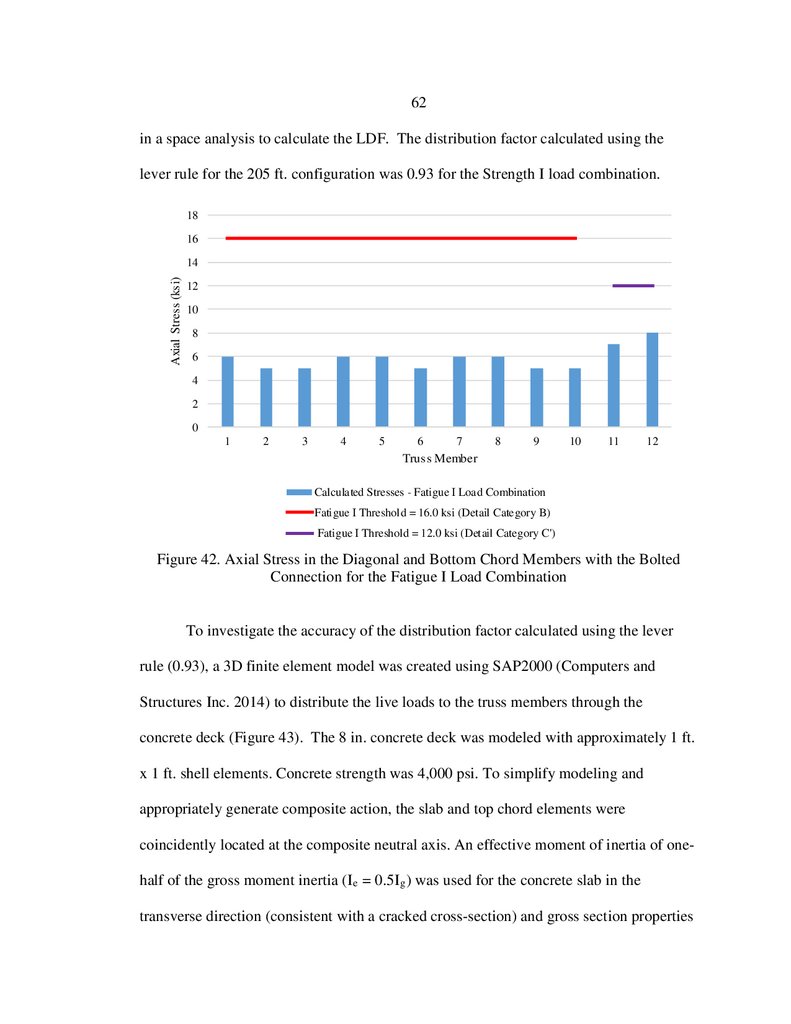


 Строительство
Похожие презентации:


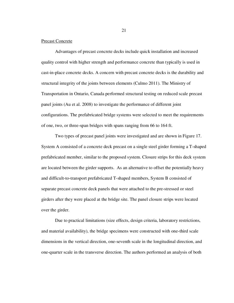
An investigation of a prefabricated steel truss girder bridge with a composite concrete deck (by Tyler William Kuehl)
1.
AN INVESTIGATION OF A PREFABRICATED STEEL TRUSSGIRDER BRIDGE WITH A COMPOSITE CONCRETE DECK
by
Tyler William Kuehl
A thesis submitted in partial fulfillment
of the requirements for the degree
of
Master of Science
in
Civil Engineering
MONTANA STATE UNIVERSITY
Bozeman, Montana
April 2018
2.
©COPYRIGHTby
Tyler William Kuehl
2018
All Rights Reserved
3.
iiACKNOWLEDGEMENTS
I would like to express the upmost gratitude to my advisor, Dr. Damon Fick, who
aided me in my coursework and research during my time at Montana State University. I
would also like to recognize the other members of my committee, Dr. Jerry Stephens, Dr.
Mike Berry, and Mr. Anders Larsson for their contributions to my research and
education.
An additional note of gratitude is extended to the various other professors and
graduate students who helped with my research and education along the way. Thank you
to the Montana Department of Transportation who provided the funding for the research.
Lastly, I would like to extend a thank you to my wife, Alyson Kuehl, who has stood by
my side through the many years of schooling and came on this adventure of moving
across the country to Montana.
4.
iiiTABLE OF CONTENTS
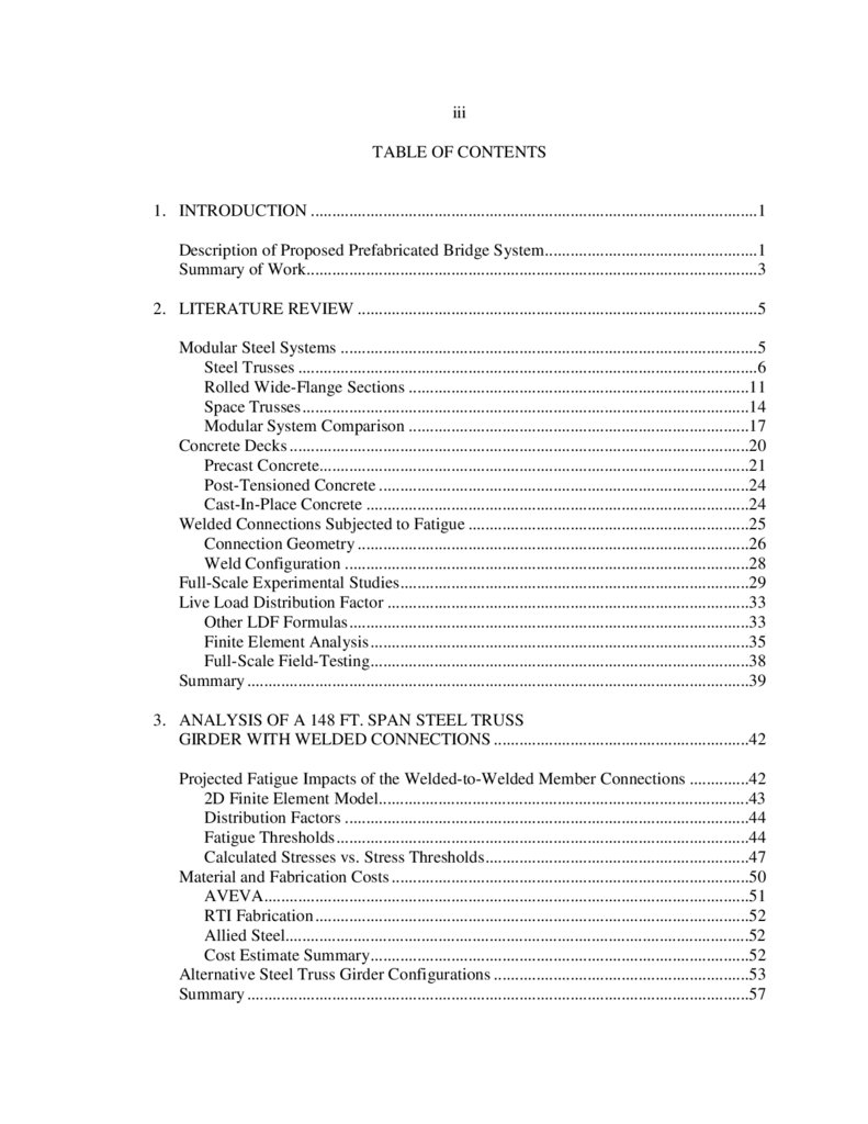
1. INTRODUCTION .........................................................................................................1
Description of Proposed Prefabricated Bridge System ..................................................1
Summary of Work..........................................................................................................3
2. LITERATURE REVIEW ..............................................................................................5
Modular Steel Systems ..................................................................................................5
Steel Trusses ............................................................................................................6
Rolled Wide-Flange Sections ................................................................................11
Space Trusses .........................................................................................................14
Modular System Comparison ................................................................................17
Concrete Decks ............................................................................................................20
Precast Concrete.....................................................................................................21
Post-Tensioned Concrete .......................................................................................24
Cast-In-Place Concrete ..........................................................................................24
Welded Connections Subjected to Fatigue ..................................................................25
Connection Geometry ............................................................................................26
Weld Configuration ...............................................................................................28
Full-Scale Experimental Studies ..................................................................................29
Live Load Distribution Factor .....................................................................................33
Other LDF Formulas ..............................................................................................33
Finite Element Analysis .........................................................................................35
Full-Scale Field-Testing.........................................................................................38
Summary ......................................................................................................................39
3. ANALYSIS OF A 148 FT. SPAN STEEL TRUSS
GIRDER WITH WELDED CONNECTIONS ............................................................42
Projected Fatigue Impacts of the Welded-to-Welded Member Connections ..............42
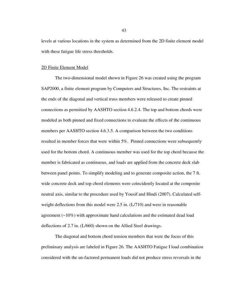
2D Finite Element Model.......................................................................................43
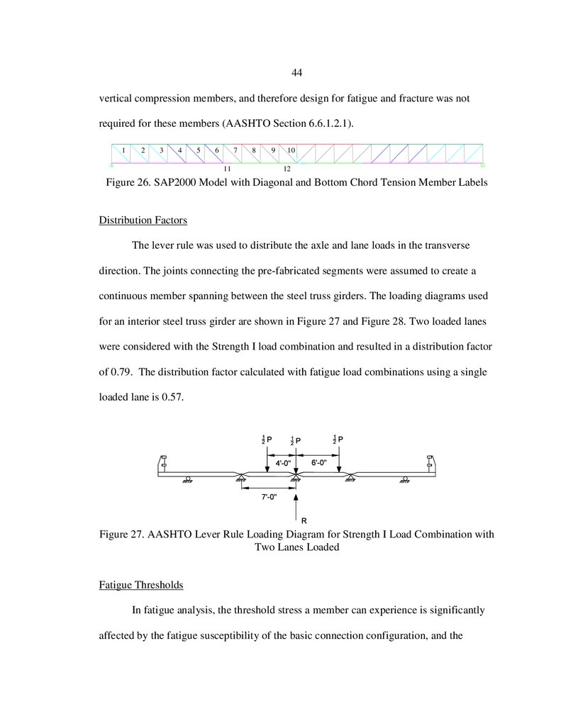
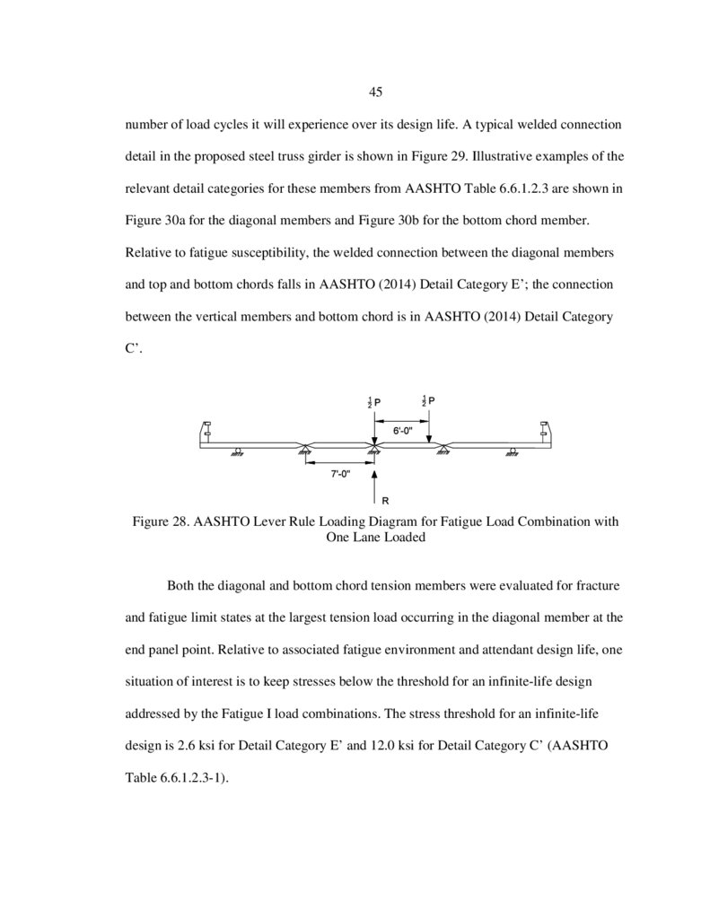
Distribution Factors ...............................................................................................44
Fatigue Thresholds .................................................................................................44
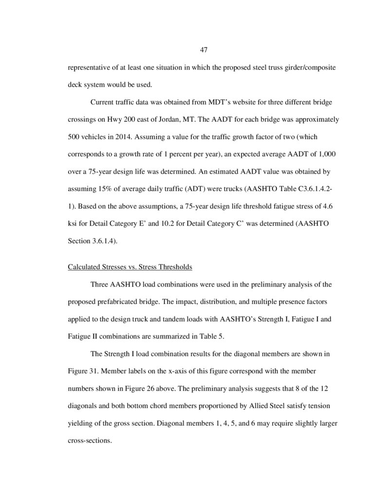
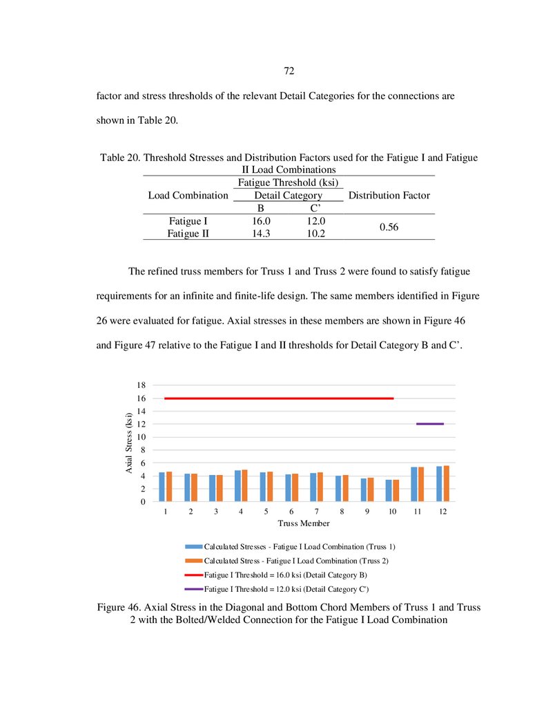
Calculated Stresses vs. Stress Thresholds ..............................................................47
Material and Fabrication Costs ....................................................................................50
AVEVA..................................................................................................................51
RTI Fabrication ......................................................................................................52
Allied Steel.............................................................................................................52
Cost Estimate Summary.........................................................................................52
Alternative Steel Truss Girder Configurations ............................................................53
Summary ......................................................................................................................57
5.
ivTABLE OF CONTENTS CONTINUED
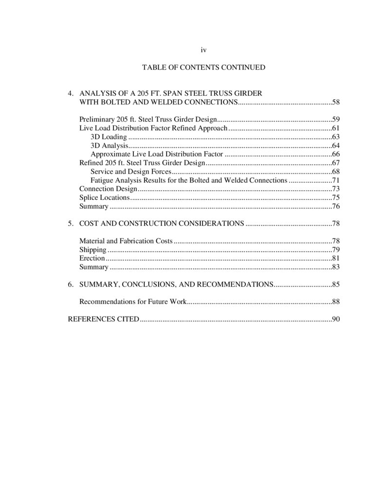
4. ANALYSIS OF A 205 FT. SPAN STEEL TRUSS GIRDER
WITH BOLTED AND WELDED CONNECTIONS..................................................58
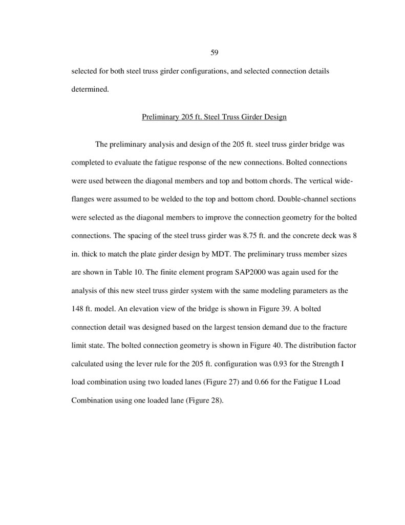
Preliminary 205 ft. Steel Truss Girder Design.............................................................59
Live Load Distribution Factor Refined Approach .......................................................61
3D Loading ............................................................................................................63
3D Analysis ............................................................................................................64
Approximate Live Load Distribution Factor .........................................................66
Refined 205 ft. Steel Truss Girder Design ...................................................................67
Service and Design Forces .....................................................................................68
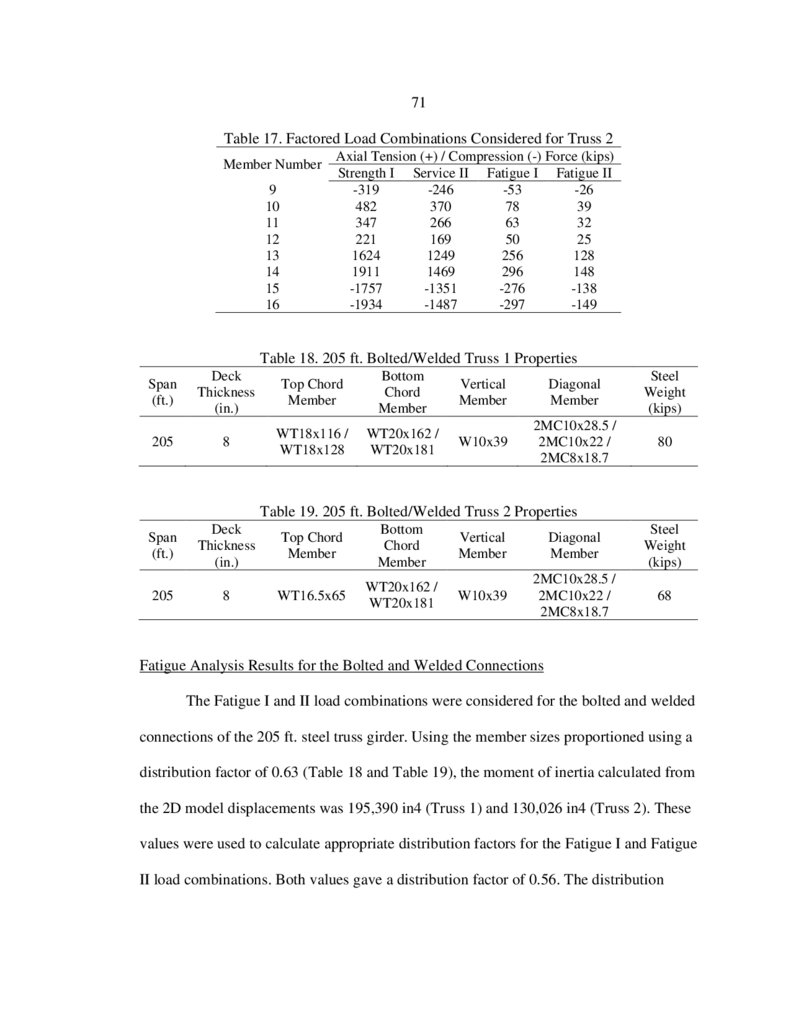
Fatigue Analysis Results for the Bolted and Welded Connections .......................71
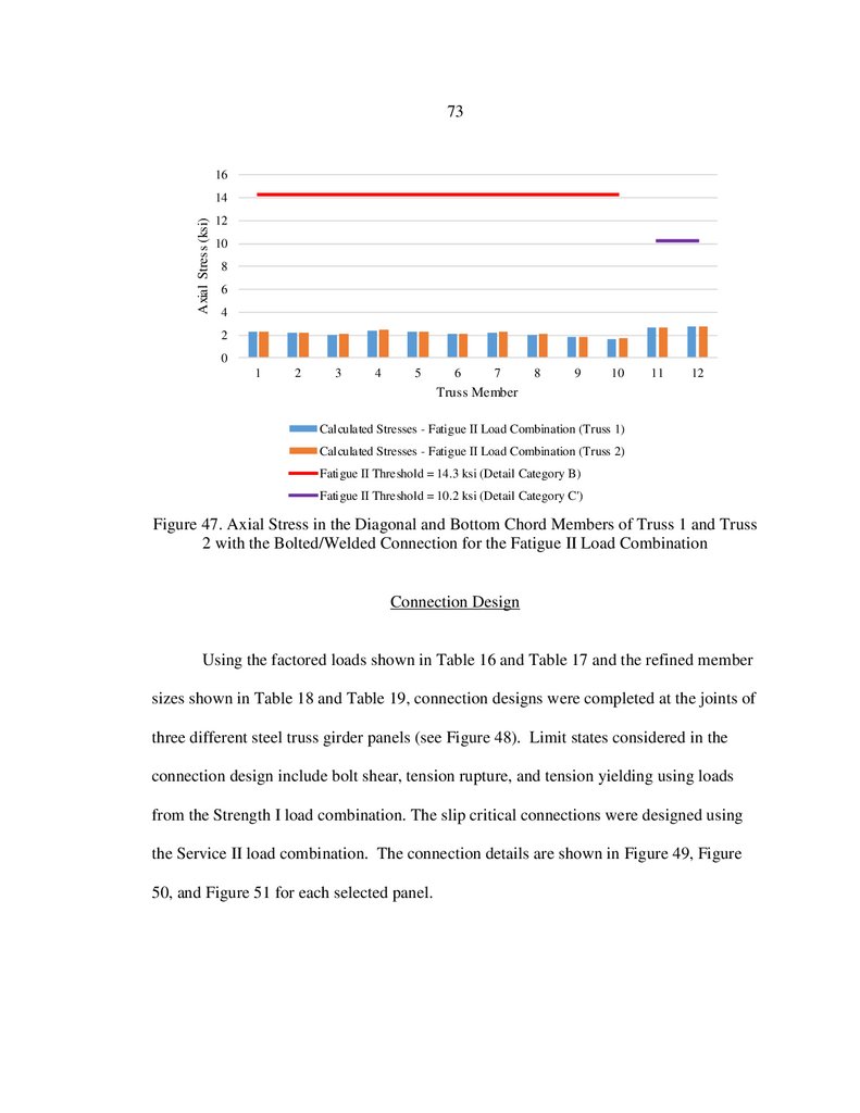
Connection Design .......................................................................................................73
Splice Locations ...........................................................................................................75
Summary ......................................................................................................................76
5. COST AND CONSTRUCTION CONSIDERATIONS ..............................................78
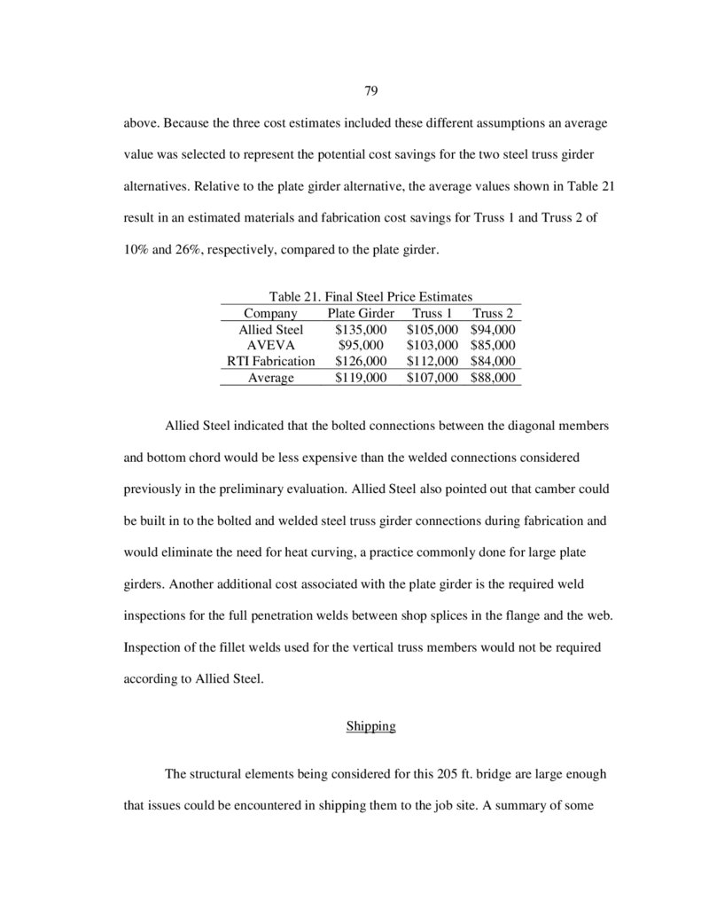
Material and Fabrication Costs ....................................................................................78
Shipping .......................................................................................................................79
Erection ........................................................................................................................81
Summary ......................................................................................................................83
6. SUMMARY, CONCLUSIONS, AND RECOMMENDATIONS...............................85
Recommendations for Future Work.............................................................................88
REFERENCES CITED ......................................................................................................90
6.
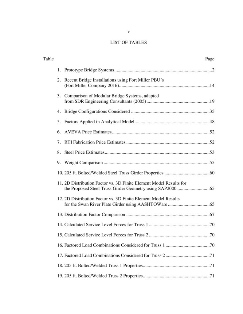
vLIST OF TABLES
Table
Page
1. Prototype Bridge Systems ..................................................................................2
2. Recent Bridge Installations using Fort Miller PBU’s
(Fort Miller Company 2016)............................................................................14
3. Comparison of Modular Bridge Systems, adapted
from SDR Engineering Consultants (2005) .....................................................19
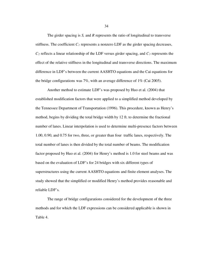
4. Bridge Configurations Considered ..................................................................35
5. Factors Applied in Analytical Model ...............................................................48
6. AVEVA Price Estimates ..................................................................................52
7. RTI Fabrication Price Estimates ......................................................................52
8. Steel Price Estimates ........................................................................................53
9. Weight Comparison .........................................................................................55
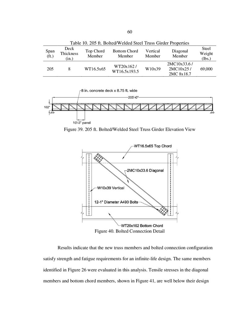
10. 205 ft. Bolted/Welded Steel Truss Girder Properties ......................................60
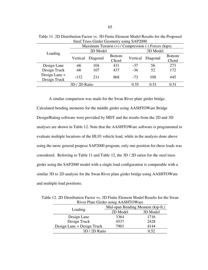
11. 2D Distribution Factor vs. 3D Finite Element Model Results for
the Proposed Steel Truss Girder Geometry using SAP2000 ...........................65
12. 2D Distribution Factor vs. 3D Finite Element Model Results
for the Swan River Plate Girder using AASHTOWare ...................................65
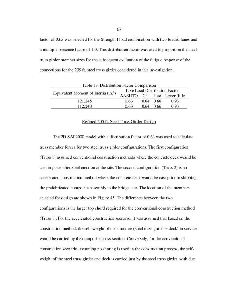
13. Distribution Factor Comparison ......................................................................67
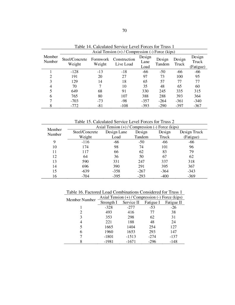
14. Calculated Service Level Forces for Truss 1 ...................................................70
15. Calculated Service Level Forces for Truss 2 ...................................................70
16. Factored Load Combinations Considered for Truss 1 .....................................70
17. Factored Load Combinations Considered for Truss 2 .....................................71
18. 205 ft. Bolted/Welded Truss 1 Properties ........................................................71
19. 205 ft. Bolted/Welded Truss 2 Properties ........................................................71
7.
viLIST OF TABLES CONTINUED
Table
Page
20. Threshold Stresses and Distribution Factors used for
the Fatigue I and Fatigue II Load Combinations .............................................72
21. Final Steel Price Estimates...............................................................................79
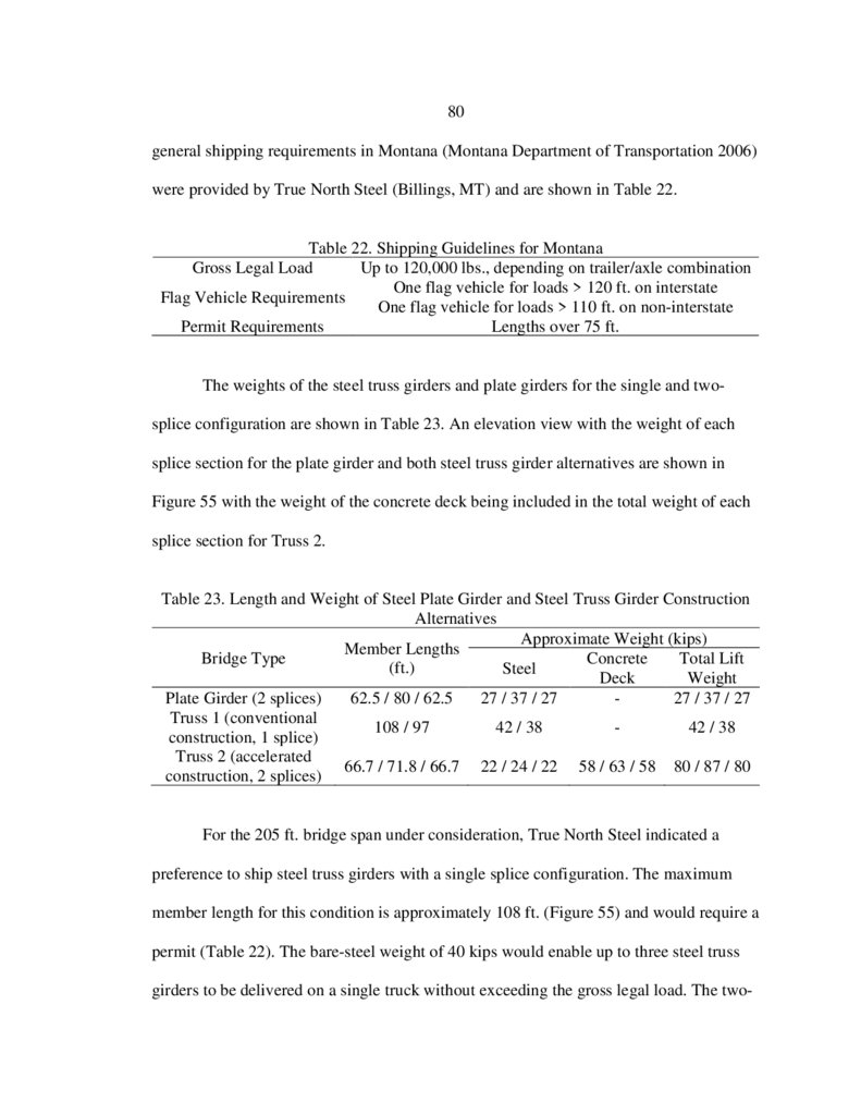
22. Shipping Guidelines for Montana ....................................................................80
23. Length and Weight of Steel Plate Girder and Steel
Truss Girder Construction Alternatives ...........................................................80
8.
viiLIST OF FIGURES
Figure
Page
1. Proposed (a) Cross-Section and (b) Elevation View of
the Prefabricated Steel Truss Girder Bridge Option 1 .......................................2
2. Detail of a Bailey Bridge Panel (Klaiber and Wipf 2004) .................................6
3. Bailey Configurations (SDR Engineering Consultants 2005) ...........................7
4. Bailey Bridge Launching Diagram
(SDR Engineering Consultants 2005)................................................................7
5. Acrow Bridge assembled using Several Layers of Panels
to Achieve the Span (Acrow Corporation of America 2015) ............................8
6. US Bridge Design, the “Viking Bridge” (U.S. Bridge 2015) ..........................10
7. Crosier Bottom Crossing (McConahy 2004) ...................................................12
8. Prefabricated Wide-Flange Beams topped
with a Composite Concrete Deck ....................................................................13
9. Prefabricated Bridge Units cast Upside-Down
(Fort Miller Company 2016)............................................................................13
10. I-87 Prefabricated Bridge Unit Installation, I-87 Bridge
Reconstruction (Fort Miller Company 2016) ..................................................14
11. Roize (a) Cross-Section and (b) Elevation View (Muller 1993) .....................15
12. Space Truss Superstructure of the Roize Bridge (Muller 1993) ......................16
13. Lully Viaduct (a) Cross-Section and (b) Elevation View,
SI Dimensions (Dauner et al. 1998).................................................................17
14. Lully Viaduct Space Truss (Dauner et al. 1998)..............................................17
15. Modular Precast Concrete Bridge Concept
(SDR Engineering Consultants 2005)..............................................................19
16. Continuous Precast Modular Bridge Concept
(SDR Engineering Consultants 2005)..............................................................20
9.
viiiLIST OF FIGURES CONTINUED
Figure
Page
17. Typical Transverse Sections of Prefabricated
Bridge System Specimens (Au et al. 2008) .....................................................22
18. Closure Strip Details for Four Configurations
Considered (Au et al. 2008) .............................................................................23
19. Proposed Cross-Section for a Cast-In-Place Concrete Deck
without Formwork (SDR Engineering Consultants 2005)...............................25
20. Connection Configurations Tested (Battistini et al. 2014) ..............................27
21. Angle-Plate Cross-Frame Specimens (McDonald and Frank 2009)................28
22. Full-Scale Bailey Bridge Model (King et al. 2013) .........................................30
23. Hillsville Truss (Hickey et al. 2009) ................................................................31
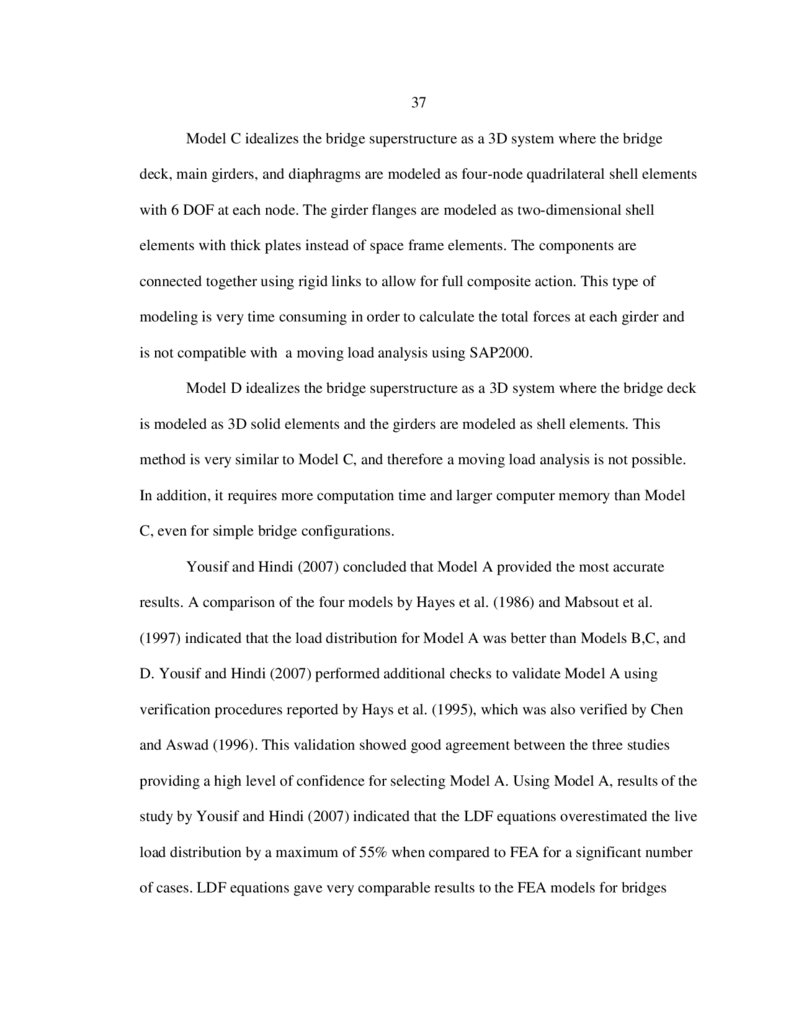
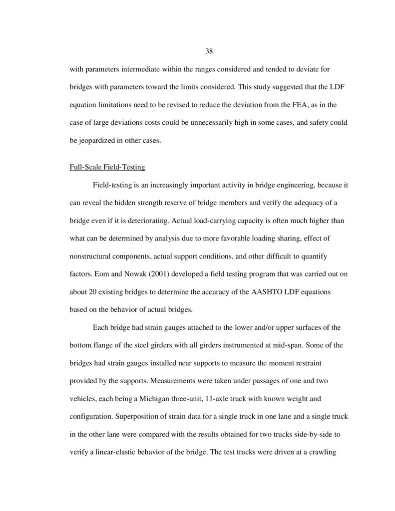
24. Finite Element Model A Technique
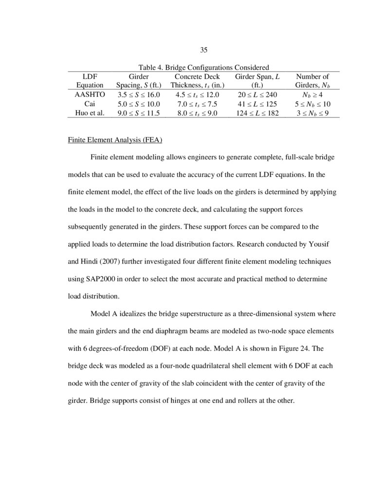
(Yousif and Hindi 2007) ..................................................................................36
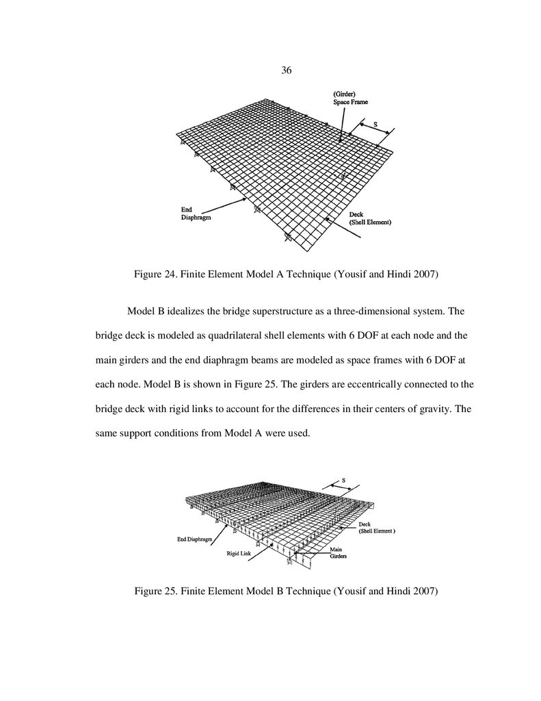
25. Finite Element Model B Technique
(Yousif and Hindi 2007) ..................................................................................36
26. SAP2000 Model with Diagonal and Bottom
Chord Tension Member Labels .......................................................................44
27. AASHTO Lever Rule Loading Diagram for Strength I
Load Combination with Two Lanes Loaded ...................................................44
28. AASHTO Lever Rule Loading Diagram for Fatigue
Load Combination with One Lane Loaded ......................................................45
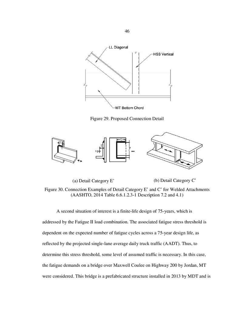
29. Proposed Connection Detail ............................................................................46
30. Connection Examples of Detail Category E’ and C’ for
Welded Attachments (AASHTO, 2014 Table
6.6.1.2.3-1 Description 7.2 and 4.1) ................................................................46
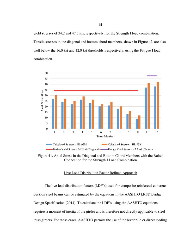
31. Axial Stress in the Diagonal and Bottom Chord Members with
the Welded Connection for the Strength I Load Combination ........................48
10.
ixLIST OF FIGURES CONTINUED
Figure
Page
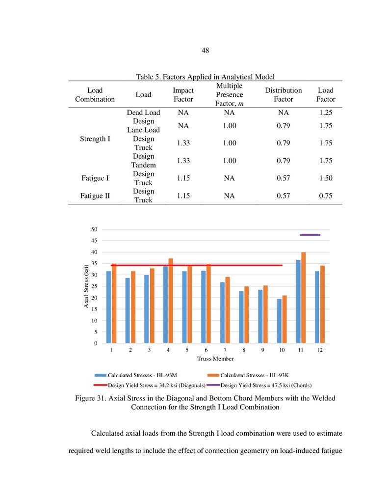
32. Axial Stress in the Diagonal and Bottom Chord Members with
the Welded Connection for the Fatigue I Load Combination ..........................49
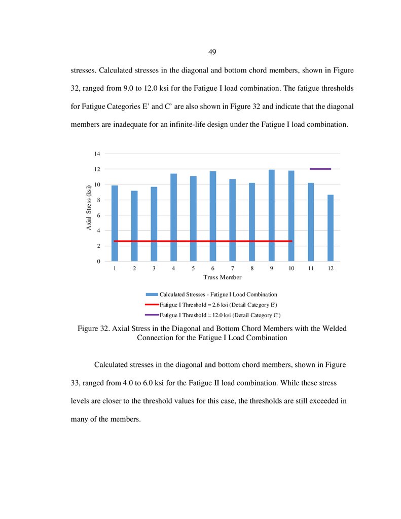
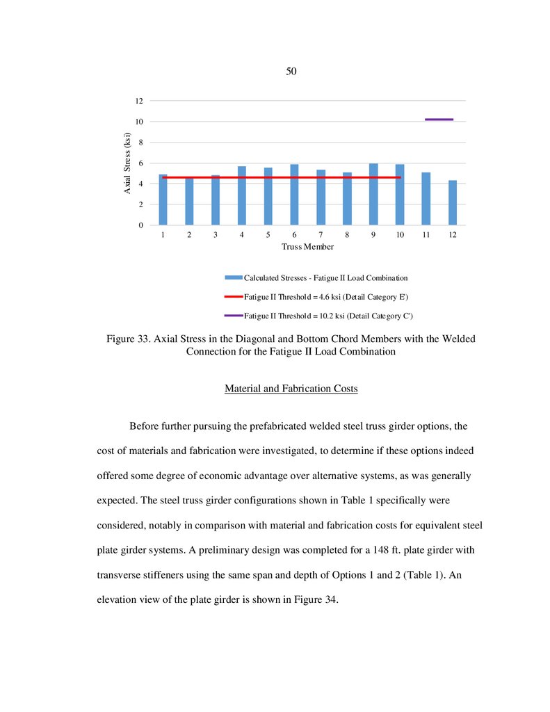
33. Axial Stress in the Diagonal and Bottom Chord Members with
the Welded Connection for the Fatigue II Load Combination ........................50
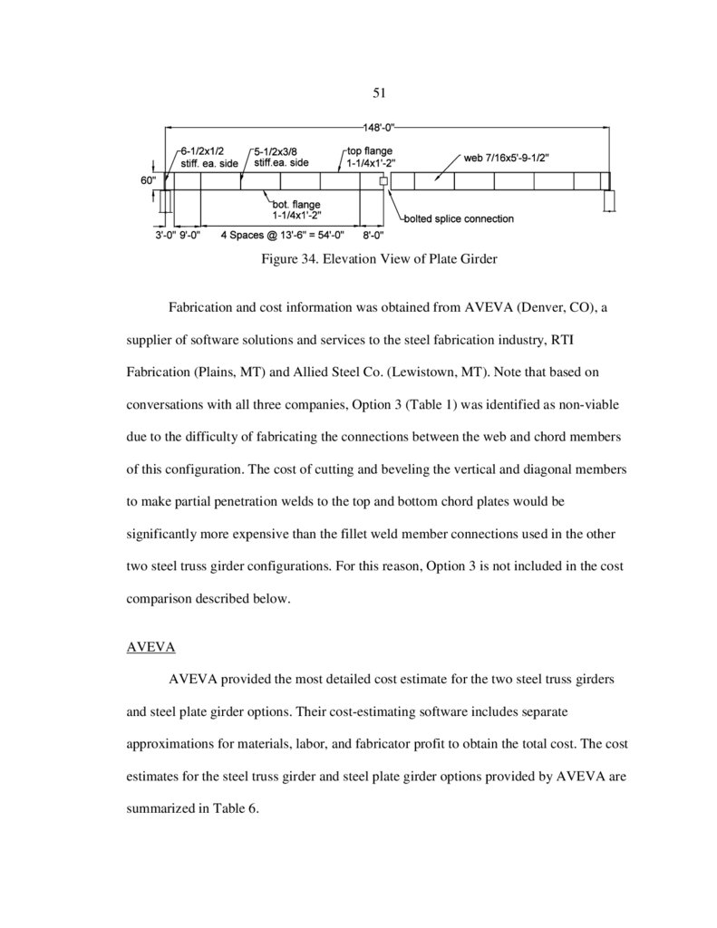
34. Elevation View of Plate Girder ........................................................................51
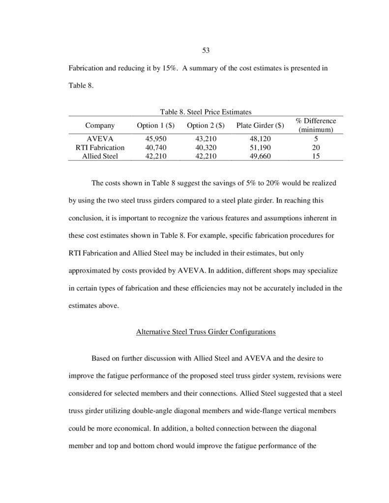
35. Diagonal Member Connection Examples of Detail Category B for
Longitudinally Loaded Bolted Attachments (AASHTO 2014
Table 6.6.1.2.3-1 Description 2.5) ...................................................................54
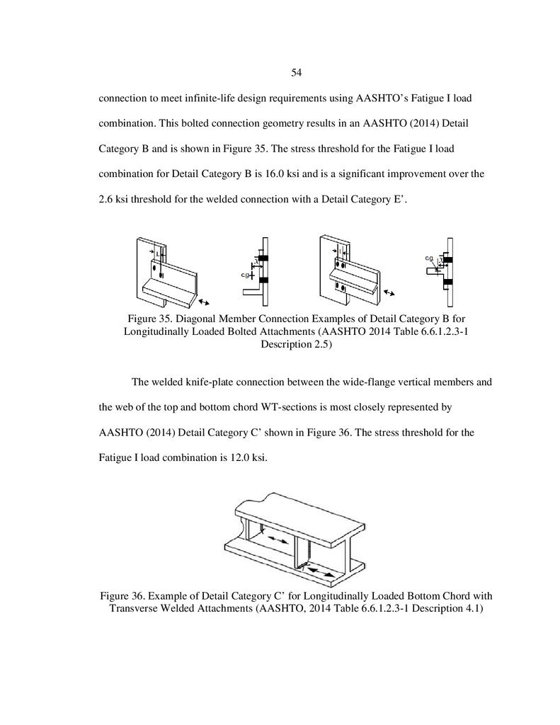
36. Example of Detail Category C’ for Longitudinally Loaded
Bottom Chord with Transverse Welded Attachments
(AASHTO, 2014 Table 6.6.1.2.3-1 Description 4.1).......................................54
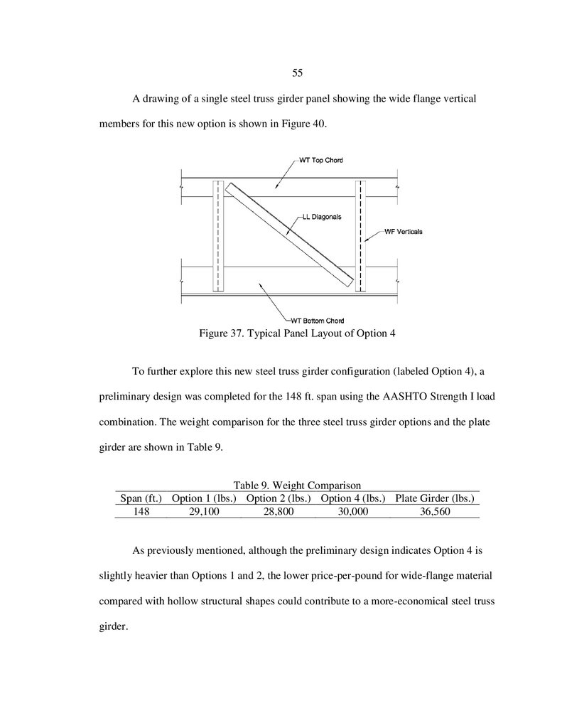
37. Typical Panel Layout of Option 4....................................................................55
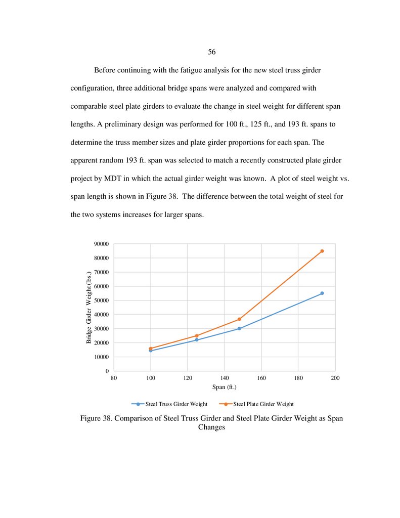
38. Comparison of Steel Truss Girder and Steel Plate
Girder Weight as Span Changes ......................................................................56
39. 205 ft. Bolted/Welded Steel Truss Girder Elevation View..............................60
40. Bolted Connection Detail .................................................................................60
41. Axial Stress in the Diagonal and Bottom Chord Members with
the Bolted Connection for the Strength I Load Combination ..........................61
42. Axial Stress in the Diagonal and Bottom Chord Members with
the Bolted Connection for the Fatigue I Load Combination............................62
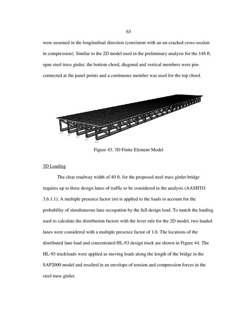
43. 3D Finite Element Model.................................................................................63
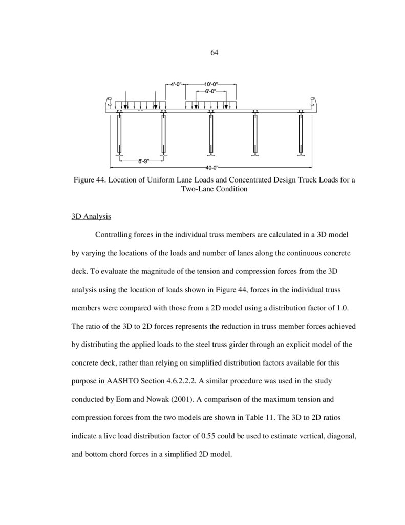
44. Location of Uniform Lane Loads and Concentrated Design
Truck Loads for a Two-Lane Condition ..........................................................64
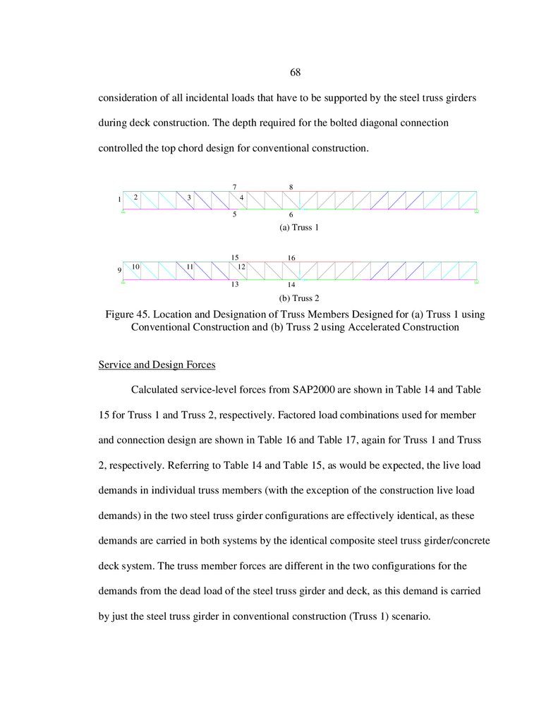
45. Location and Designation of Truss Members Designed
for (a) Truss 1 using Conventional Construction and
(b) Truss 2 using Accelerated Construction.....................................................68
11.
xLIST OF FIGURES CONTINUED
Figure
Page
46. Axial Stress in the Diagonal and Bottom Chord Members
of Truss 1 and Truss 2 with the Bolted/Welded Connection
for the Fatigue I Load Combination.................................................................72
47. Axial Stress in the Diagonal and Bottom Chord Members
of Truss 1 and Truss 2 with the Bolted/Welded Connection
for the Fatigue II Load Combination ...............................................................73
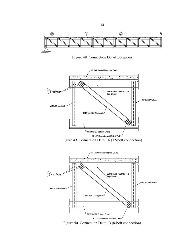
48. Connection Detail Locations............................................................................74
49. Connection Detail A (12-bolt connection) .......................................................74
50. Connection Detail B (8-bolt connection) .........................................................74
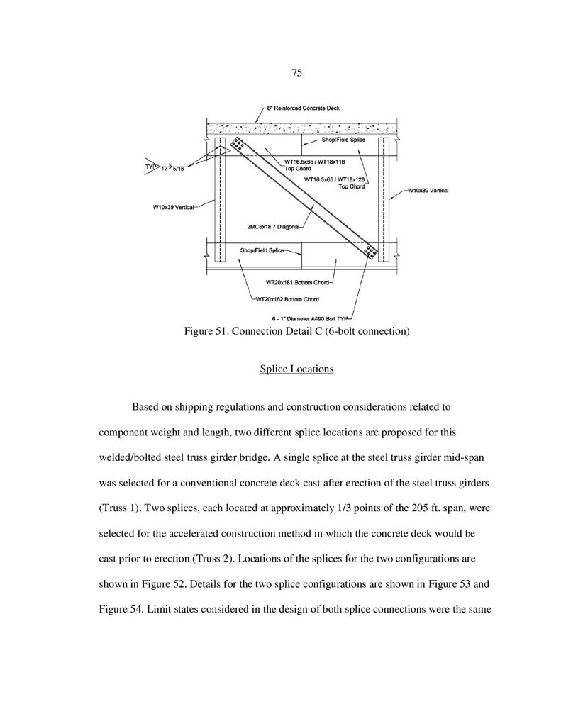
51. Connection Detail C (6-bolt connection) .........................................................75
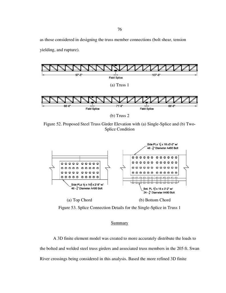
52. Proposed Steel Truss Girder Elevation with (a) Single-Splice
and (b) Two-Splice Condition .........................................................................76
53. Splice Connection Details for the Single-Splice in Truss 1 .............................76
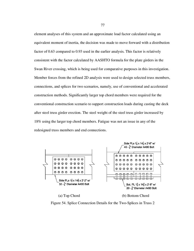
54. Splice Connection Details for the Two-Splices in Truss 2 ..............................77
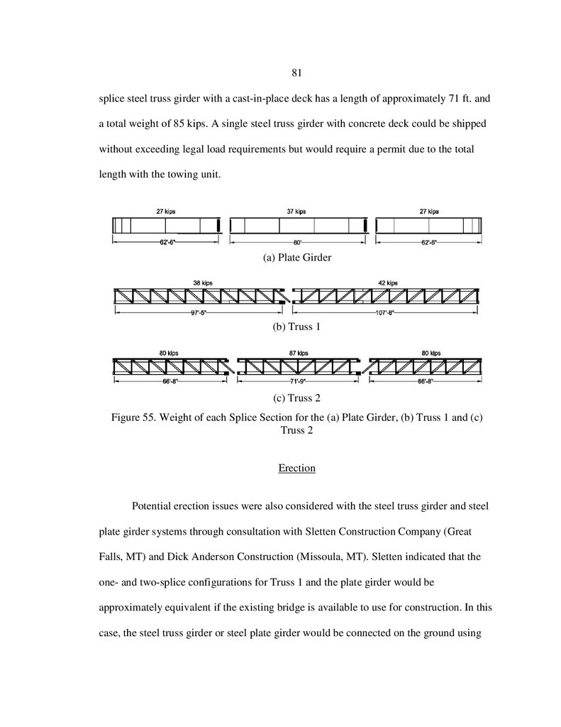
55. Weight of each Splice Section for the (a) Plate Girder,
(b) Truss 1 and (c) Truss 2 ...............................................................................81
12.
xiABSTRACT
Steel truss girder bridges are an efficient and aesthetic option for highway
crossings. Their relatively light weight compared with steel plate girder systems make
them a desirable alternative for both material savings and constructability. A prototype of
a welded steel truss girder constructed with an integral concrete deck has been proposed
as a potential alternative for accelerated bridge construction (ABC) projects in Montana.
This system consists of a prefabricated welded steel truss girder topped with a concrete
deck that can be cast at the fabrication facility (for ABC projects) or in the field after
erection (for conventional projects). To investigate possible solutions to the fatigue
limitations of certain welded member connections in these steel truss girders, bolted
connections between the diagonal tension members and the top and bottom chords of the
steel truss girders were evaluated.
A 3D finite element model was used to more accurately represent the distribution
of lane and truckloads to the individual steel truss girders. This distribution was
compared to an approximate factor calculated using an equivalent moment of inertia with
expressions for steel plate girders from AASHTO. A 2D analytical model was used to
investigate the fatigue strength of the bolted and welded connections for both a
conventional cast in place deck system and an accelerated bridge deck system (cast
integral with the steel truss girder).
Truss members and connections for both construction alternatives were designed
using loads from AASHTO Strength I, Fatigue I, Fatigue II, and Service II load
combinations. A comparison was made between the two steel truss girder configurations
and 205 ft. steel plate girder used in a previously designed bridge over the Swan River.
Material and fabrication estimates suggest the cost of the conventional and accelerated
construction methods is 10% and 26% less, respectively, than the steel plate girder
designed for the Swan River crossing.
13.
1CHAPTER ONE
INTRODUCTION
A prototype bridge structure has been proposed as a potential alternative for
accelerated bridge construction (ABC) projects in Montana. Accelerated bridge
construction is rapidly gaining momentum in the United States as a common bridge
building practice due to the increased safety and decreased impact on the public that
results from the associated reduced construction times. The proposed system consists of a
prefabricated welded steel truss girder topped with a composite concrete deck cast-inplace at the fabrication facility. These composite members are transported to the site,
where they are set next to each other on a prepared foundation to create the bridge.
Description of Proposed Prefabricated Bridge System
Allied Steel completed preliminary designs for three different prefabricated steel
truss girder/integral concrete deck bridge systems, namely two configurations of a 148 ft.
bridge over Cooper Creek (Thompson Falls, MT) and a 108 ft. bridge over Big Dry
Creek (Jordan, MT). The prefabricated elements for these systems consist of a single
steel truss girder supporting 10 ft. - 4 in. (Big Dry Creek) and 7 ft. (Cooper Creek) wide
concrete decks cast at the steel fabrication facility. Member sizes for these preliminary
designs are shown in Table 1.
In all cases, the vertical and diagonal steel truss girder members are welded to the
top and bottom chords of the steel truss girder. Two (or more) prefabricated elements are
14.
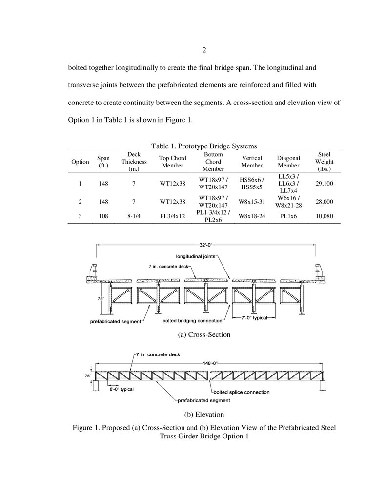
2bolted together longitudinally to create the final bridge span. The longitudinal and
transverse joints between the prefabricated elements are reinforced and filled with
concrete to create continuity between the segments. A cross-section and elevation view of
Option 1 in Table 1 is shown in Figure 1.
Table 1. Prototype Bridge Systems
Option
Span
(ft.)
Deck
Thickness
(in.)
Top Chord
Member
Bottom
Chord
Member
Vertical
Member
1
148
7
WT12x38
WT18x97 /
WT20x147
HSS6x6 /
HSS5x5
2
148
7
WT12x38
3
108
8-1/4
PL3/4x12
WT18x97 /
WT20x147
PL1-3/4x12 /
PL2x6
W8x15-31
W8x18-24
Diagonal
Member
LL5x3 /
LL6x3 /
LL7x4
W6x16 /
W8x21-28
PL1x6
Steel
Weight
(lbs.)
29,100
28,000
10,080
(a) Cross-Section
(b) Elevation
Figure 1. Proposed (a) Cross-Section and (b) Elevation View of the Prefabricated Steel
Truss Girder Bridge Option 1
15.
3Summary of Work
The literature review (Chapter 2) identified the current state-of-practice related to
the analysis, design, and construction of similar bridge systems constructed on an
accelerated schedule. The review focused on four primary topics pertinent to the
proposed bridge system and this project: 1) modular systems, 2) concrete decks, 3)
welded connections subjected to fatigue, 4) full-scale experimental studies, and 5) live
load distribution factors.
The objectives of Chapter 3 were to 1) identify any impacts on the projected
service life of the prototype steel truss girder bridge configurations based on fatigue of
the welded member-to-member connections, 2) perform a cost analysis for the proposed
systems and compare the results with the cost of plate girder alternatives, 3) as necessary
and possible, suggest potential generic changes in member connection details to improve
fatigue performance, and 4) for a specific 205 ft. span, identify a steel truss bridge
configuration with the greatest potential for material and construction efficiencies. The
205 ft. span was selected so that these results could be readily compared with the Swan
River plate girder project currently being designed by MDT.
In Chapter 4, a bolted/welded prefabricated steel truss girder bridge was
investigated as an alternative to the welded steel truss girder bridge. Use of bolted
connections at selected locations in the steel truss girders offers improved fatigue
performance, allowing for lighter weight members, and making it a viable alternative for
bridge replacement projects using either conventional or accelerated construction
methods. The proposed system consists of bolted diagonal and welded vertical member
16.
4connections to the top and bottom chords. Tasks included 1) developing a 3D finite
element model used to more accurately calculate the distribution of lane and truck loads
to the steel truss girder members, 2) investigating approximate distribution factors using
an equivalent moment of inertia, and 3) determining member sizes and connection
geometry to satisfy AASHTO Strength I, Fatigue I, and Service II load combinations for
both conventional and accelerated construction methods.
The final designs of the two steel truss girder configurations developed in Chapter
4 were used in Chapter 5 to estimate potential cost savings related to materials,
fabrication, and construction of these alternatives compared with the 205 ft. Swan River
plate girders.
Summary and conclusions are presented in Chapter 6.
17.
5CHAPTER TWO
LITERATURE REVIEW
In reviewing prefabricated bridge systems with a view toward investigating their
deployment, five subject areas of interest were identified and researched in the literature:
1) modular steel systems, 2) concrete decks, 3) welded connections subjected to fatigue,
4) full-scale experimental studies, and 5) live load distribution factors. Each topic,
discussed in the following subsections, was selected for its impact on the analysis, design
and construction of a prefabricated steel-truss bridge in Montana.
With these topics in mind, a thorough search was performed using four resource
databases: Engineering Village, MDT Library, Transportation Research Board, and
Google Scholar. The keyword “Prefabricated Bridges” was successfully combined with
“Steel Truss,” and “Deck Systems” to identify potential works of interest. The articles
were reviewed and further organized into categories related to the components of the
proposed modular steel system. This review and filtering process identified 37 sources
(journal publications, trade journal articles, and state, federal, and private reports) as the
most relevant to the proposed prefabricated steel truss girder bridge.
Modular Steel Systems
Prefabricated steel bridges have been constructed using a truss configuration,
most notably in the Bailey Bridge and its successors. Other prefabricated steel systems
include steel girders with composite concrete decks and composite space trusses.
18.
6Steel Trusses
One of the earliest forms of prefabricated bridges was the Bailey Bridge. Patented
in 1943, the Bailey Bridge was designed by Sir Donald Bailey for use by the Allied
Forces to build crossings during World War II (SDR Engineering Consultants 2005). A
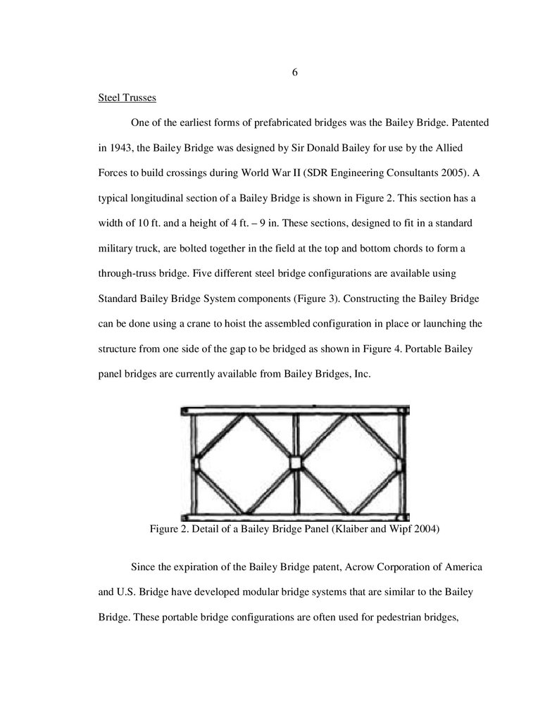
typical longitudinal section of a Bailey Bridge is shown in Figure 2. This section has a
width of 10 ft. and a height of 4 ft. – 9 in. These sections, designed to fit in a standard
military truck, are bolted together in the field at the top and bottom chords to form a
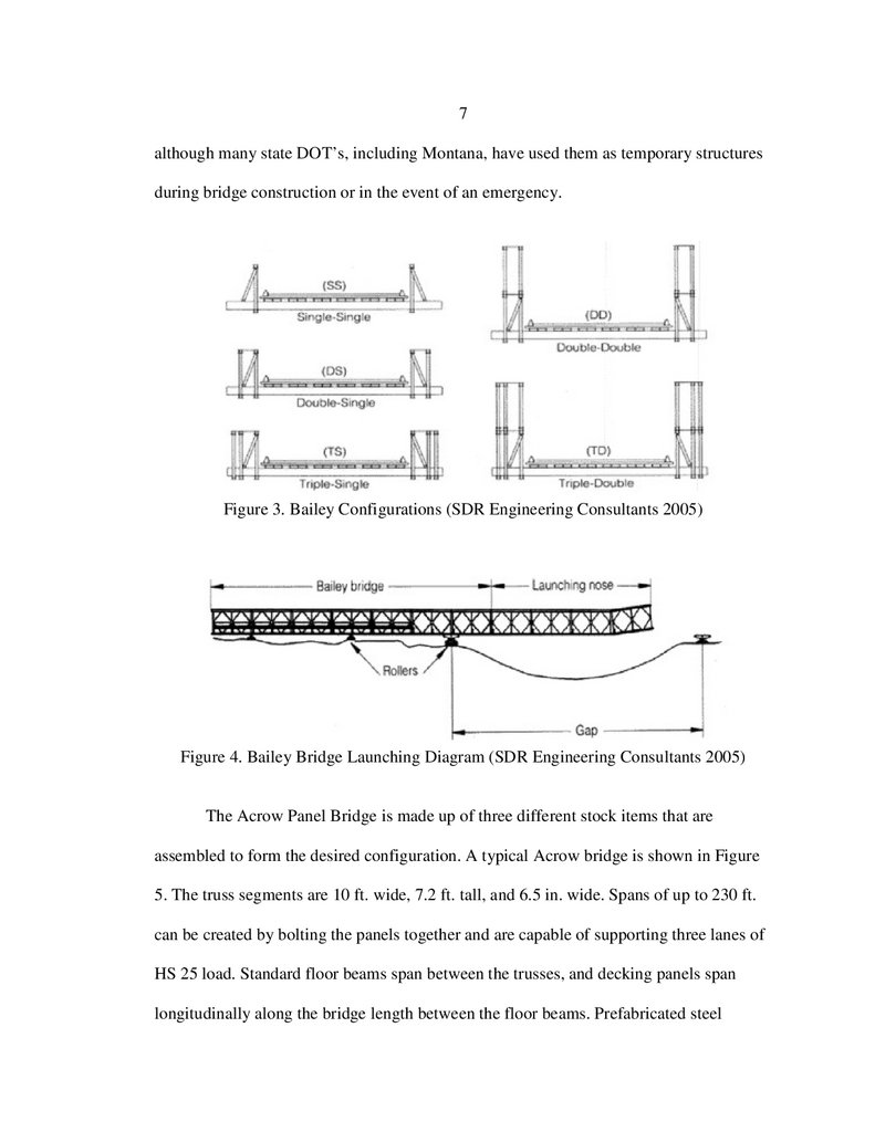
through-truss bridge. Five different steel bridge configurations are available using
Standard Bailey Bridge System components (Figure 3). Constructing the Bailey Bridge
can be done using a crane to hoist the assembled configuration in place or launching the
structure from one side of the gap to be bridged as shown in Figure 4. Portable Bailey
panel bridges are currently available from Bailey Bridges, Inc.
Figure 2. Detail of a Bailey Bridge Panel (Klaiber and Wipf 2004)
Since the expiration of the Bailey Bridge patent, Acrow Corporation of America
and U.S. Bridge have developed modular bridge systems that are similar to the Bailey
Bridge. These portable bridge configurations are often used for pedestrian bridges,
19.
7although many state DOT’s, including Montana, have used them as temporary structures
during bridge construction or in the event of an emergency.
Figure 3. Bailey Configurations (SDR Engineering Consultants 2005)
Figure 4. Bailey Bridge Launching Diagram (SDR Engineering Consultants 2005)
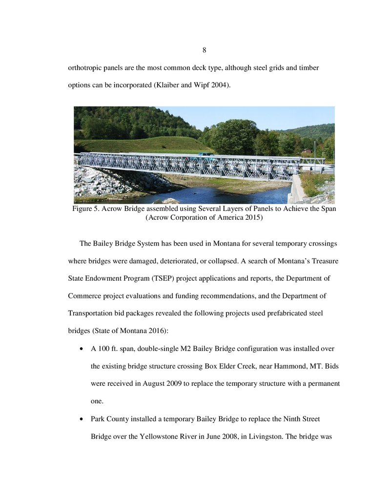
The Acrow Panel Bridge is made up of three different stock items that are
assembled to form the desired configuration. A typical Acrow bridge is shown in Figure
5. The truss segments are 10 ft. wide, 7.2 ft. tall, and 6.5 in. wide. Spans of up to 230 ft.
can be created by bolting the panels together and are capable of supporting three lanes of
HS 25 load. Standard floor beams span between the trusses, and decking panels span
longitudinally along the bridge length between the floor beams. Prefabricated steel
20.
8orthotropic panels are the most common deck type, although steel grids and timber
options can be incorporated (Klaiber and Wipf 2004).
Figure 5. Acrow Bridge assembled using Several Layers of Panels to Achieve the Span
(Acrow Corporation of America 2015)
The Bailey Bridge System has been used in Montana for several temporary crossings
where bridges were damaged, deteriorated, or collapsed. A search of Montana’s Treasure
State Endowment Program (TSEP) project applications and reports, the Department of
Commerce project evaluations and funding recommendations, and the Department of
Transportation bid packages revealed the following projects used prefabricated steel
bridges (State of Montana 2016):
A 100 ft. span, double-single M2 Bailey Bridge configuration was installed over
the existing bridge structure crossing Box Elder Creek, near Hammond, MT. Bids
were received in August 2009 to replace the temporary structure with a permanent
one.
Park County installed a temporary Bailey Bridge to replace the Ninth Street
Bridge over the Yellowstone River in June 2008, in Livingston. The bridge was
21.
9installed over the existing structure and was posted with a speed limit of 5 mph
and a maximum vehicle weight of 3 tons.
A collapsed bridge over Fish Creek near Ryegate, in Golden Valley County, was
replaced with a temporary Bailey Bridge. Bids were received in August 2014 to
replace the temporary structure with 83 ft. pre-stressed bulb-tee beams.
TSEP emergency funds were used to construct a temporary Bailey Bridge over a
damaged bridge crossing Racetrack Creek in Powell County (pre-2005).
Mineral County used a temporary Bailey Bridge over the 52 ft. damaged timber
Cedar Creek Bridge (pre-2005).
In December of 2002, Madison County installed a Bailey Bridge over the
deteriorating Upper South Boulder Bridge to provide a temporary crossing until a
permanent solution could be implemented.
The panel sizes, span lengths, and load capacities of the Bailey type bridges are
consistent with the proposed systems considered in this investigation. Their long history
demonstrates that modular prefabricated truss systems are an effective bridge
construction strategy. That being said, these bridges are used in a through truss
configuration, while the proposed systems use an underslung truss arrangement. The
decks in these systems do not act compositely with the trusses, while composite action
between the concrete decks and steel trusses in the proposed systems is expected to offer
improved structural efficiency and stiffness.
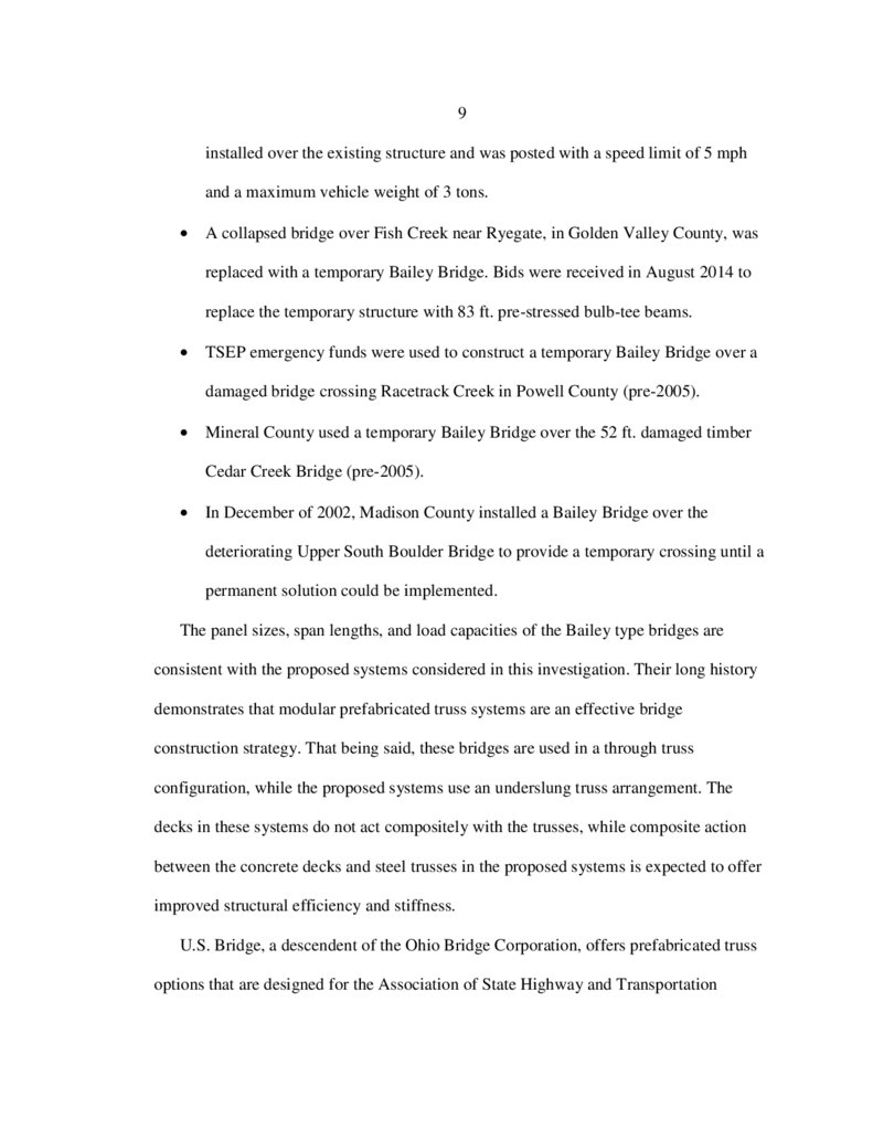
U.S. Bridge, a descendent of the Ohio Bridge Corporation, offers prefabricated truss
options that are designed for the Association of State Highway and Transportation
22.
10Officials (AASHTO) HS10, HS15, HS25, and HL93 loadings (U.S. Bridge 2015). Unlike
the Bailey/Acrow Panel Bridge, where identical panel segments are bolted together in the
field, the U.S. Bridge System uses longer, all-welded truss systems that can then be
bolted together in the field. The trusses panels are prefabricated with standard Wsections, and the entire welded segments are then hot-dipped galvanized (Klaiber and
Wipf 2004). The trusses are through-type with parallel top and bottom chords and are
available in standard lengths of up to 150 ft. For longer spans, a camel back configuration
is used and is shown in Figure 6. A common deck system includes underslung floor
beams carrying simply supported stringers. Traditional concrete filled pans and timber
decks can also be provided.
Figure 6. US Bridge Design, the “Viking Bridge” (U.S. Bridge 2015)
Completely prefabricating steel-truss bridge superstructures could potentially be a
more cost- effective and permanent solution for counties that install temporary bridge
structures. Albany County in New York State investigated this alternative to find cost-
23.
11efficient bridge solutions in rural areas with lower traffic volumes (Heine 1990). The
county replaced a 70 ft. truss bridge built in 1898 with Warren trusses and welded
connections prefabricated by the Ohio Bridge Corporation. The estimated cost to install
the bridge on the existing abutments was $50 per sq. ft. and included the cost of material,
erection, and placement of a wooden deck. Bid prices were 5 to 6 times this amount for a
standard replacement (Heine 1990).
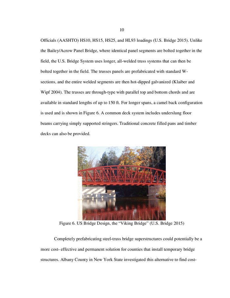
A second example of a permanent welded prefabricated truss installation is the
Crosier Bottom culvert in Meade County, Kentucky (McConahy 2004). The solution for
the bridge replacement was a design-build process using 80 ft. prefabricated steel trusses
(Figure 7). This alternative was substantially cheaper than a cast-in-place concrete bridge
(McConahy 2004). The steel trusses were a U.S. Bridge product, and each truss was
shipped in two 40-foot sections that were bolted together to form the final 80 ft. length
and then lifted by crane onto the abutments. The bridge was finished with a cast-in-place
concrete deck. The entire project, including a soil investigation, design, and construction
was completed in 30 days. A detailed timeline of the construction was not provided. The
Crosier Bottom bridge replacement highlights the benefits that prefabricated steel trusses
can provide.
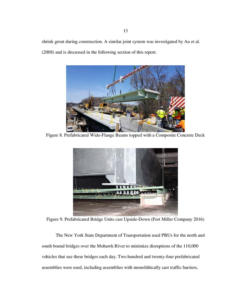
Rolled Wide-Flange Sections
Another type of prefabricated modular system consists of wide-flange beams
topped with a composite concrete deck, as shown in Figure 8. One such system,
originally patented under the name “Inverset,” is now marketed by Fort Miller Co., Inc.
(Schuylerville, NY) as Prefabricated Bridge Units (PBU). The composite system is
24.
12similar to the proposed prefabricated system of the current study; however, the
assemblies consist of two wide-flange sections, rather than steel trusses, topped with a
concrete deck. Common or typical segment sizes are not provided on Fort Miller
Company’s website.
Figure 7. Crosier Bottom Crossing (McConahy 2004)
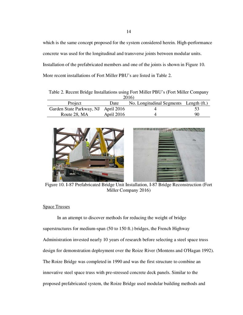
The PBU/Inverset system uses an innovative fabrication method to obtain a more
efficient composite cross-section. The segments are cast in an upside down orientation, as
shown in Figure 9, in such a manner that upon subsequent erection, stresses in the
composite elements are near zero in the bottom steel flange and are tensile in the top
concrete flange (Klaiber and Wipf 2004). The result is a more efficient section for short
to medium span bridges where stresses are dominated by live loading. The Fort Miller
PBU’s have been used for spans up to 126 ft. long with skews that exceed 45 degrees
(Fort Miller Company 2016). The specific span and width of the prefabricated segments
were not provided. Keys cast in the overhanging slabs are grouted together with non-
25.
13shrink grout during construction. A similar joint system was investigated by Au et al.
(2008) and is discussed in the following section of this report.
Figure 8. Prefabricated Wide-Flange Beams topped with a Composite Concrete Deck
Figure 9. Prefabricated Bridge Units cast Upside-Down (Fort Miller Company 2016)
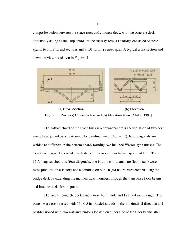
The New York State Department of Transportation used PBUs for the north and
south bound bridges over the Mohawk River to minimize disruptions of the 110,000
vehicles that use these bridges each day. Two hundred and twenty-four prefabricated
assemblies were used, including assemblies with monolithically cast traffic barriers,
26.
14which is the same concept proposed for the system considered herein. High-performance
concrete was used for the longitudinal and transverse joints between modular units.
Installation of the prefabricated members and one of the joints is shown in Figure 10.
More recent installations of Fort Miller PBU’s are listed in Table 2.
Table 2. Recent Bridge Installations using Fort Miller PBU’s (Fort Miller Company
2016)
Project
Date
No. Longitudinal Segments Length (ft.)
Garden State Parkway, NJ April 2016
4
53
Route 28, MA
April 2016
4
90
Figure 10. I-87 Prefabricated Bridge Unit Installation, I-87 Bridge Reconstruction (Fort
Miller Company 2016)
Space Trusses
In an attempt to discover methods for reducing the weight of bridge
superstructures for medium-span (50 to 150 ft.) bridges, the French Highway
Administration invested nearly 10 years of research before selecting a steel space truss
design for demonstration deployment over the Roize River (Montens and O'Hagan 1992).
The Roize Bridge was completed in 1990 and was the first structure to combine an
innovative steel space truss with pre-stressed concrete deck panels. Similar to the
proposed prefabricated system, the Roize Bridge used modular building methods and
27.
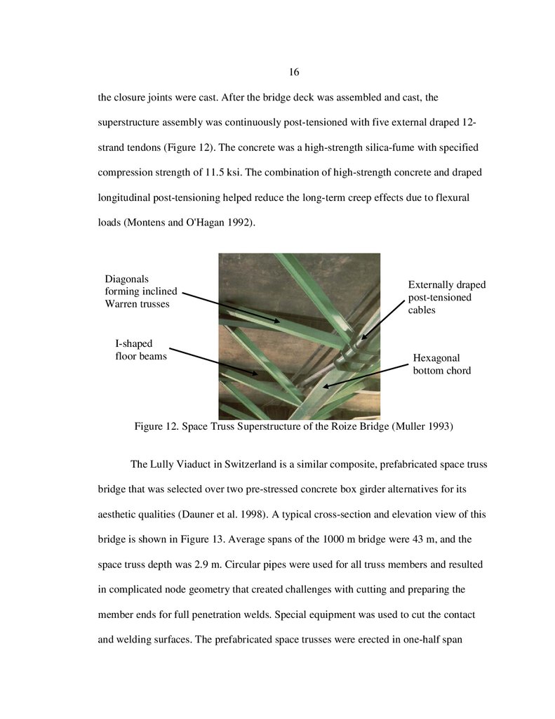
15composite action between the space truss and concrete deck, with the concrete deck
effectively acting as the “top chord” of the truss system. The bridge consisted of three
spans: two 118 ft. end sections and a 131 ft. long center span. A typical cross-section and
elevation view are shown in Figure 11.
(a) Cross-Section
(b) Elevation
Figure 11. Roize (a) Cross-Section and (b) Elevation View (Muller 1993)
The bottom chord of the space truss is a hexagonal cross section made of two bent
steel plates joined by a continuous longitudinal weld (Figure 12). Four diagonals are
welded to stiffeners in the bottom chord, forming two inclined Warren-type trusses. The
top of the diagonals is welded to I-shaped transverse floor beams spaced at 13 ft. These
13 ft. long tetrahedrons (four diagonals, one bottom chord, and one floor beam) were
mass produced in a factory and assembled on-site. Rigid nodes were created along the
bridge deck by extending the inclined truss members through the transverse floor beams
and into the deck closure pour.
The precast concrete deck panels were 40 ft. wide and 12 ft. - 4 in. in length. The
panels were pre-stressed with 54 - 0.5 in. bonded strands in the longitudinal direction and
post-tensioned with two 4-strand tendons located on either side of the floor beams after
28.
16the closure joints were cast. After the bridge deck was assembled and cast, the
superstructure assembly was continuously post-tensioned with five external draped 12strand tendons (Figure 12). The concrete was a high-strength silica-fume with specified
compression strength of 11.5 ksi. The combination of high-strength concrete and draped
longitudinal post-tensioning helped reduce the long-term creep effects due to flexural
loads (Montens and O'Hagan 1992).
Diagonals
forming inclined
Warren trusses
I-shaped
floor beams
Externally draped
post-tensioned
cables
Hexagonal
bottom chord
Figure 12. Space Truss Superstructure of the Roize Bridge (Muller 1993)
The Lully Viaduct in Switzerland is a similar composite, prefabricated space truss
bridge that was selected over two pre-stressed concrete box girder alternatives for its
aesthetic qualities (Dauner et al. 1998). A typical cross-section and elevation view of this
bridge is shown in Figure 13. Average spans of the 1000 m bridge were 43 m, and the
space truss depth was 2.9 m. Circular pipes were used for all truss members and resulted
in complicated node geometry that created challenges with cutting and preparing the
member ends for full penetration welds. Special equipment was used to cut the contact
and welding surfaces. The prefabricated space trusses were erected in one-half span
29.
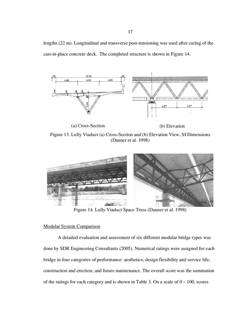
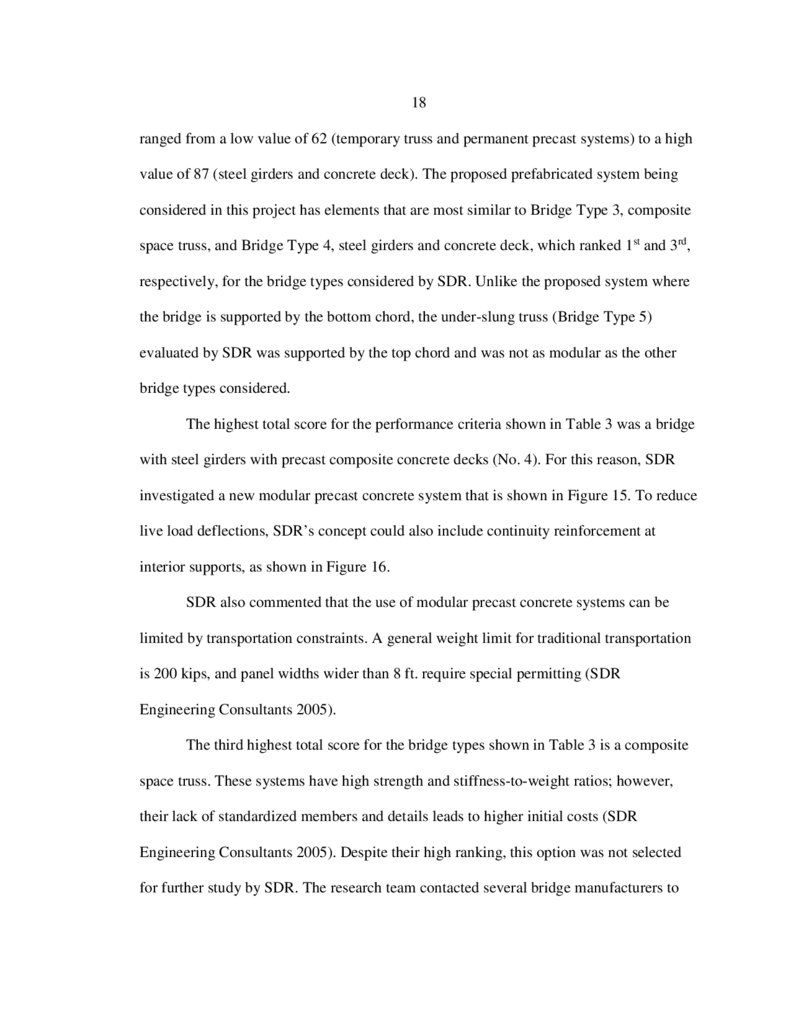
17lengths (22 m). Longitudinal and transverse post-tensioning was used after curing of the
cast-in-place concrete deck. The completed structure is shown in Figure 14.
(a) Cross-Section
(b) Elevation
Figure 13. Lully Viaduct (a) Cross-Section and (b) Elevation View, SI Dimensions
(Dauner et al. 1998)
Figure 14. Lully Viaduct Space Truss (Dauner et al. 1998)
Modular System Comparison
A detailed evaluation and assessment of six different modular bridge types was
done by SDR Engineering Consultants (2005). Numerical ratings were assigned for each
bridge in four categories of performance: aesthetics; design flexibility and service life;
construction and erection; and future maintenance. The overall score was the summation
of the ratings for each category and is shown in Table 3. On a scale of 0 – 100, scores
30.
18ranged from a low value of 62 (temporary truss and permanent precast systems) to a high
value of 87 (steel girders and concrete deck). The proposed prefabricated system being
considered in this project has elements that are most similar to Bridge Type 3, composite
space truss, and Bridge Type 4, steel girders and concrete deck, which ranked 1st and 3rd,
respectively, for the bridge types considered by SDR. Unlike the proposed system where
the bridge is supported by the bottom chord, the under-slung truss (Bridge Type 5)
evaluated by SDR was supported by the top chord and was not as modular as the other
bridge types considered.
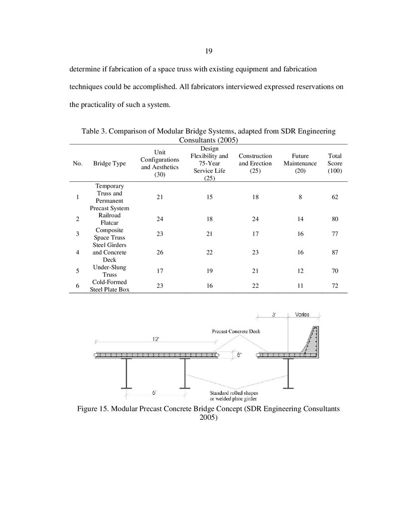
The highest total score for the performance criteria shown in Table 3 was a bridge
with steel girders with precast composite concrete decks (No. 4). For this reason, SDR
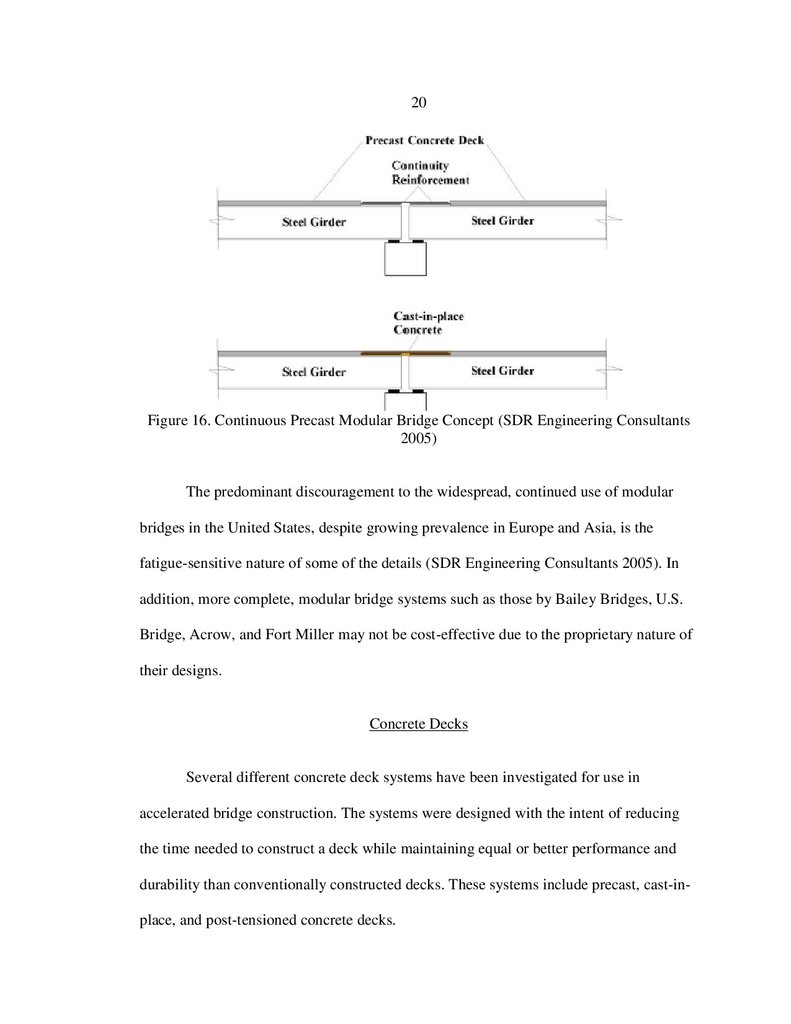
investigated a new modular precast concrete system that is shown in Figure 15. To reduce
live load deflections, SDR’s concept could also include continuity reinforcement at
interior supports, as shown in Figure 16.
SDR also commented that the use of modular precast concrete systems can be
limited by transportation constraints. A general weight limit for traditional transportation
is 200 kips, and panel widths wider than 8 ft. require special permitting (SDR
Engineering Consultants 2005).
The third highest total score for the bridge types shown in Table 3 is a composite
space truss. These systems have high strength and stiffness-to-weight ratios; however,
their lack of standardized members and details leads to higher initial costs (SDR
Engineering Consultants 2005). Despite their high ranking, this option was not selected
for further study by SDR. The research team contacted several bridge manufacturers to
31.
19determine if fabrication of a space truss with existing equipment and fabrication
techniques could be accomplished. All fabricators interviewed expressed reservations on
the practicality of such a system.
Table 3. Comparison of Modular Bridge Systems, adapted from SDR Engineering
Consultants (2005)
No.
1
2
3
4
5
6
Bridge Type
Temporary
Truss and
Permanent
Precast System
Railroad
Flatcar
Composite
Space Truss
Steel Girders
and Concrete
Deck
Under-Slung
Truss
Cold-Formed
Steel Plate Box
Unit
Configurations
and Aesthetics
(30)
Design
Flexibility and
75-Year
Service Life
(25)
Construction
and Erection
(25)
Future
Maintenance
(20)
Total
Score
(100)
21
15
18
8
62
24
18
24
14
80
23
21
17
16
77
26
22
23
16
87
17
19
21
12
70
23
16
22
11
72
Figure 15. Modular Precast Concrete Bridge Concept (SDR Engineering Consultants
2005)
32.
20Figure 16. Continuous Precast Modular Bridge Concept (SDR Engineering Consultants
2005)
The predominant discouragement to the widespread, continued use of modular
bridges in the United States, despite growing prevalence in Europe and Asia, is the
fatigue-sensitive nature of some of the details (SDR Engineering Consultants 2005). In
addition, more complete, modular bridge systems such as those by Bailey Bridges, U.S.
Bridge, Acrow, and Fort Miller may not be cost-effective due to the proprietary nature of
their designs.
Concrete Decks
Several different concrete deck systems have been investigated for use in
accelerated bridge construction. The systems were designed with the intent of reducing
the time needed to construct a deck while maintaining equal or better performance and
durability than conventionally constructed decks. These systems include precast, cast-inplace, and post-tensioned concrete decks.
33.
21Precast Concrete
Advantages of precast concrete decks include quick installation and increased
quality control with higher strength and performance concrete than typically is used in
cast-in-place concrete decks. A concern with precast concrete decks is the durability and
structural integrity of the joints between elements (Culmo 2011). The Ministry of
Transportation in Ontario, Canada performed structural testing on reduced scale precast
panel joints (Au et al. 2008) to investigate the performance of different joint
configurations. The prefabricated bridge systems were selected to meet the requirements
of one, two, or three-span bridges with spans ranging from 66 to 164 ft.
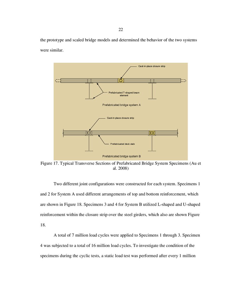
Two types of precast panel joints were investigated and are shown in Figure 17.
System A consisted of a concrete deck precast on a single steel girder forming a T-shaped
prefabricated member, similar to the proposed system. Closure strips for this deck system
are located between the girder supports. As an alternative to offset the potentially heavy
and difficult-to-transport prefabricated T-shaped members, System B consisted of
separate precast concrete deck panels that were attached to the pre-stressed or steel
girders after they were placed at the bridge site. The panel closure strips were located
over the girder.
Due to practical limitations (size effects, design criteria, laboratory restrictions,
and material availability), the bridge specimens were constructed with one-third scale
dimensions in the vertical direction, one-seventh scale in the longitudinal direction, and
one-quarter scale in the transverse direction. The authors performed an analysis of both
34.
22the prototype and scaled bridge models and determined the behavior of the two systems
were similar.
Figure 17. Typical Transverse Sections of Prefabricated Bridge System Specimens (Au et
al. 2008)
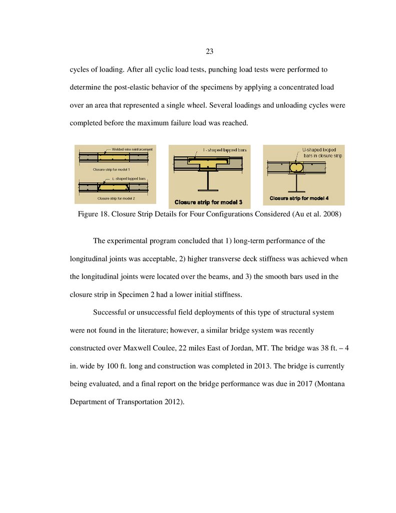
Two different joint configurations were constructed for each system. Specimens 1
and 2 for System A used different arrangements of top and bottom reinforcement, which
are shown in Figure 18. Specimens 3 and 4 for System B utilized L-shaped and U-shaped
reinforcement within the closure strip over the steel girders, which also are shown Figure
18.
A total of 7 million load cycles were applied to Specimens 1 through 3. Specimen
4 was subjected to a total of 16 million load cycles. To investigate the condition of the
specimens during the cyclic tests, a static load test was performed after every 1 million
35.
23cycles of loading. After all cyclic load tests, punching load tests were performed to
determine the post-elastic behavior of the specimens by applying a concentrated load
over an area that represented a single wheel. Several loadings and unloading cycles were
completed before the maximum failure load was reached.
Figure 18. Closure Strip Details for Four Configurations Considered (Au et al. 2008)
The experimental program concluded that 1) long-term performance of the
longitudinal joints was acceptable, 2) higher transverse deck stiffness was achieved when
the longitudinal joints were located over the beams, and 3) the smooth bars used in the
closure strip in Specimen 2 had a lower initial stiffness.
Successful or unsuccessful field deployments of this type of structural system
were not found in the literature; however, a similar bridge system was recently
constructed over Maxwell Coulee, 22 miles East of Jordan, MT. The bridge was 38 ft. – 4
in. wide by 100 ft. long and construction was completed in 2013. The bridge is currently
being evaluated, and a final report on the bridge performance was due in 2017 (Montana
Department of Transportation 2012).
36.
24Post-Tensioned Concrete
Transverse post-tensioning in concrete deck slabs is a common method for
connecting precast concrete segments and could be used with the proposed bridge
system. The tendons could be threaded through ducts in the prefabricated slab and
grouted after post-tensioning. Research has shown that transverse post-tensioning
improves the performance of the shear key joint and the durability of the bridge decks by
reducing the number and width of cracks (Grace et al. 2012; Poston 1984). Satisfactory
performance of transverse post-tensioned joints was observed in an experimental program
conducted on a precast concrete deck panel system subjected to static and fatigue loading
(Yamane et al. 1995). This deck system was designed and developed specifically for
rapid construction and rehabilitation.
One of the challenges with post-tensioning deck panels assembled on site are
construction tolerances. In a case study in Michigan (Attanayake et al. 2014), posttensioning ducts were misaligned because the skew of the bridge was not correctly
considered. When placing the precast panels on the pre-stressed bridge girders, some of
the shear connector pockets did not provide enough tolerance for the twist (sweep) of the
beams. This particular case study demonstrated the importance of providing adequate
tolerances on precast members for efficient construction.
Cast-In-Place Concrete
Full-depth cast-in-place concrete decks are not a viable option for accelerated
bridge construction due to the formwork and shoring required during construction. A
partial-depth cast-in-place system that includes a precast or pre-manufactured form
37.
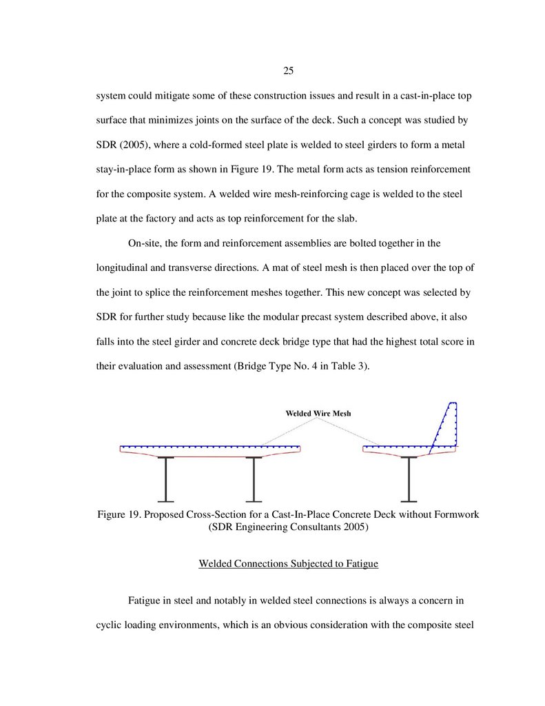
25system could mitigate some of these construction issues and result in a cast-in-place top
surface that minimizes joints on the surface of the deck. Such a concept was studied by
SDR (2005), where a cold-formed steel plate is welded to steel girders to form a metal
stay-in-place form as shown in Figure 19. The metal form acts as tension reinforcement
for the composite system. A welded wire mesh-reinforcing cage is welded to the steel
plate at the factory and acts as top reinforcement for the slab.
On-site, the form and reinforcement assemblies are bolted together in the
longitudinal and transverse directions. A mat of steel mesh is then placed over the top of
the joint to splice the reinforcement meshes together. This new concept was selected by
SDR for further study because like the modular precast system described above, it also
falls into the steel girder and concrete deck bridge type that had the highest total score in
their evaluation and assessment (Bridge Type No. 4 in Table 3).
Figure 19. Proposed Cross-Section for a Cast-In-Place Concrete Deck without Formwork
(SDR Engineering Consultants 2005)
Welded Connections Subjected to Fatigue
Fatigue in steel and notably in welded steel connections is always a concern in
cyclic loading environments, which is an obvious consideration with the composite steel
38.
26truss/concrete deck modular system being studied in this project. The welded connection
types included in the proposed prefabricated system are longitudinal welds in a knifeplate configuration and transverse welds made at the ends of the vertical and diagonal
web members. The research summarized below identifies recent articles related to
connection geometry and weld configuration that can be applied to the investigation of
the proposed system.
Connection Geometry
Extensive testing was carried out at the University of Texas at Austin with regard
to fatigue strength of welded connections used in steel bridges (Battistini et al. 2014). The
experimental program investigated the fatigue performance of five cross-frame
connection configurations by measuring stiffness, ultimate strength, and fatigue
resistance. The project objectives were to determine the connection type that was most
economical to fabricate and construct, while still providing adequate strength and
stiffness for the connecting members.
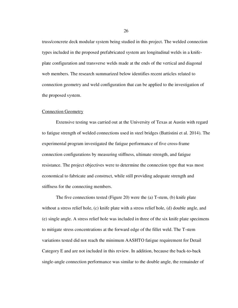
The five connections tested (Figure 20) were the (a) T-stem, (b) knife plate
without a stress relief hole, (c) knife plate with a stress relief hole, (d) double angle, and
(e) single angle. A stress relief hole was included in three of the six knife plate specimens
to mitigate stress concentrations at the forward edge of the fillet weld. The T-stem
variations tested did not reach the minimum AASHTO fatigue requirement for Detail
Category E and are not included in this review. In addition, because the back-to-back
single-angle connection performance was similar to the double angle, the remainder of
39.
27this section will focus on the two knife plate connections (b, c) and the double- angle
connection (d) shown in Figure 20.
(a) T-Stem
(b) Knife Plate
(KP)
(c) KP with
Stress Relief
(d) Double-Angle
(e) Single-Angle
Figure 20. Connection Configurations Tested (Battistini et al. 2014)
Many of the results presented were related to the specific behavior of different
brace configurations, such as X-, Z-, and K-frames. Improvements to fatigue behavior
were observed in some of these frame configurations when thicker center gusset plates
were used and when an additional transverse weld was included on the reverse side of the
angle. The following specific conclusions were made related to the fatigue tests and
welded connections:
The T-stem connections (square, round, and diamond) had poor fatigue
performance, likely due to a small local eccentricity that existed in the geometry.
The knife plate connection performed adequately in fatigue, with 5 of the 6
specimens achieving E classification; the stress relief hole further increased the
connection fatigue life.
40.
28The double-angles achieved connection E classification. The fatigue cracking
initiated in the angle when the member stress range was larger than the gusset
plate stress range.
The measured fatigue life of the connections tested in this study correlated well
with the tabulated fatigue categories provided by AASHTO for common
connection geometries.
Weld Configuration
The influence of weld geometry was investigated by McDonald and Frank (2009)
to determine if balanced welds had an influence on the fatigue strength of single-angle
connections. This study attempted to estimate fatigue performance based on the
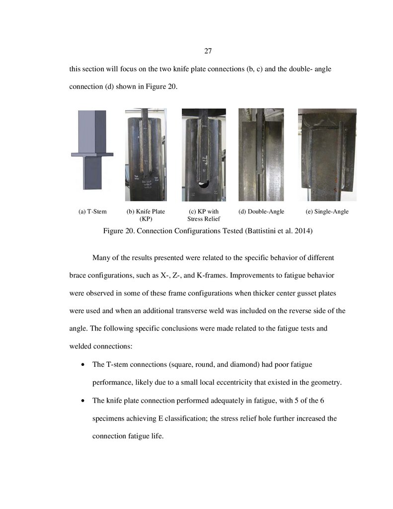
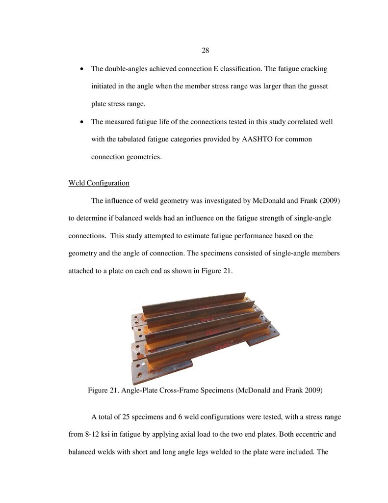
geometry and the angle of connection. The specimens consisted of single-angle members
attached to a plate on each end as shown in Figure 21.
Figure 21. Angle-Plate Cross-Frame Specimens (McDonald and Frank 2009)
A total of 25 specimens and 6 weld configurations were tested, with a stress range
from 8-12 ksi in fatigue by applying axial load to the two end plates. Both eccentric and
balanced welds with short and long angle legs welded to the plate were included. The
41.
29balanced welds were detailed to meet the requirements of AASHTO (2012). The study
concluded that the balanced welds consistently performed better than specimens with
equal length welds; however, due to the fact that angle and plate length varied, it was
inconclusive as to whether the balancing of welds or frame geometry led to improved
fatigue performance.
A parametric study using finite element analysis (FEA) was also performed by
McDonald and Frank (2009) to investigate the factors affecting the stress concentrations
in the steel plate connected to the single angles. The results of the parametric study
suggested that the factor with the highest influence on the stress concentration was the
length of the outstanding leg of the angle. Battistini et al. (2014) focused their parametric
analysis on the axial stiffness reduction factor for a single angle cross frame. They
concluded that the length of the diagonal member of a frame affects the stiffness as well,
with a longer diagonal increasing the magnitude of the reduction factor.
Full-Scale Experimental Studies
Full-scale tests on bridge systems with elements similar to those being
investigated here were identified in the literature and provide information relevant to the
strength and analytical modeling aspects of steel trusses.
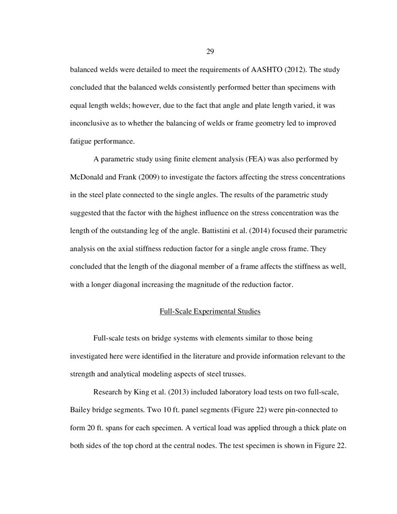
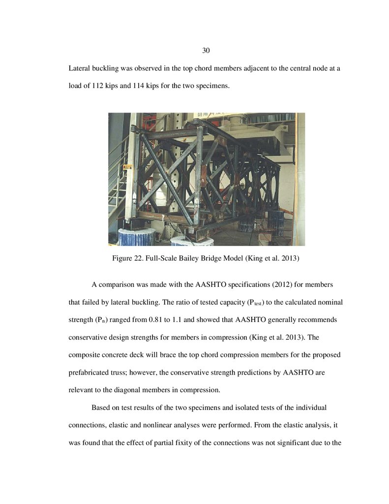
Research by King et al. (2013) included laboratory load tests on two full-scale,
Bailey bridge segments. Two 10 ft. panel segments (Figure 22) were pin-connected to
form 20 ft. spans for each specimen. A vertical load was applied through a thick plate on
both sides of the top chord at the central nodes. The test specimen is shown in Figure 22.
42.
30Lateral buckling was observed in the top chord members adjacent to the central node at a
load of 112 kips and 114 kips for the two specimens.
Figure 22. Full-Scale Bailey Bridge Model (King et al. 2013)
A comparison was made with the AASHTO specifications (2012) for members
that failed by lateral buckling. The ratio of tested capacity (P test ) to the calculated nominal
strength (P n ) ranged from 0.81 to 1.1 and showed that AASHTO generally recommends
conservative design strengths for members in compression (King et al. 2013). The
composite concrete deck will brace the top chord compression members for the proposed
prefabricated truss; however, the conservative strength predictions by AASHTO are
relevant to the diagonal members in compression.
Based on test results of the two specimens and isolated tests of the individual
connections, elastic and nonlinear analyses were performed. From the elastic analysis, it
was found that the effect of partial fixity of the connections was not significant due to the
43.
31connections remaining elastic during the test. Results from the 2D nonlinear analysis
compared well with the measured load displacement response, but the predicted capacity
was higher because the analytical model could not capture the out-of-plane stability
behavior that was observed in the test (King et al. 2013).
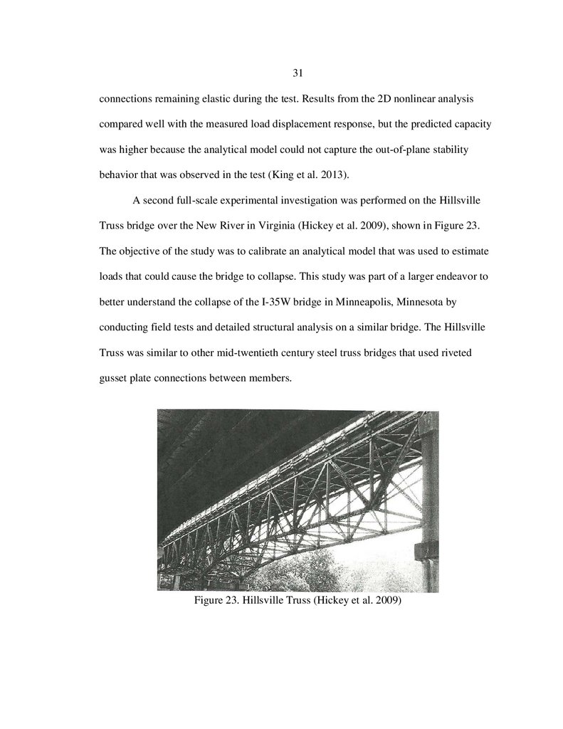
A second full-scale experimental investigation was performed on the Hillsville
Truss bridge over the New River in Virginia (Hickey et al. 2009), shown in Figure 23.
The objective of the study was to calibrate an analytical model that was used to estimate
loads that could cause the bridge to collapse. This study was part of a larger endeavor to
better understand the collapse of the I-35W bridge in Minneapolis, Minnesota by
conducting field tests and detailed structural analysis on a similar bridge. The Hillsville
Truss was similar to other mid-twentieth century steel truss bridges that used riveted
gusset plate connections between members.
Figure 23. Hillsville Truss (Hickey et al. 2009)
44.
32Loaded trucks with known dimensions and weights were parked along the bridge,
and strain gauges were strategically placed to record various member responses. The field
test results were used to calibrate a 2-dimensional linear elastic steel truss bridge model,
after which a failure analysis was conducted. The truss model with simple connections at
the joints did not correlate with the data, so the model was updated to a frame model
where bending moment could be considered. Adding the transverse floor beams and
stringer elements to the frame model resulted in calculated results that most closely
correlated with the collected data (Hickey et al. 2009). The authors concluded that the
models provided evidence that moment was being transferred through the connections of
the truss members, and therefore the connections should be evaluated to include flexural
stresses.
An important observation from the analytical modeling of the Bailey Bridge
segments and Hillsville Truss is that different conclusions were made related to the
restraint provided by the connections. The welded connections for the Bailey Bridge did
not provide significant restraint to member rotations and the results suggested the
connections could be modeled as pinned. The pinned connections assumed for the riveted
gusset plate connections in the Hillsville Truss however, did not compare well with the
measured data, and additional connection restraint was necessary. These are important
observations for the analytical modeling task of the current research project and were
included in the analysis of the proposed prefabricated system.
45.
33Live Load Distribution Factor
The live load distribution factor equations in the AASHTO LRFD Bridge Design
Specification (2014) were developed under National Cooperative Highway Research
Program Project 12-26 (Zokaie et al. 1991). This project was initiated to improve the
accuracy of the S/D formulas contained in the AASHTO specifications (Standard 1996).
The girder spacing is S, and D is a constant based on the bridge type and the number of
design lanes loaded. The S/D formulas generated valid results for bridges of typical
geometry (i.e., girder spacing near 6 ft. and span length of about 60 ft.), but notably were
less accurate for bridge spans shorter or longer than 60 ft. (Zokaie 2000). For these cases,
span length and stiffness properties must be considered to gain better accuracy. This
study led to the development of a set of formulas that provided better accuracy and
included a broader range of bridges. These new equations first appeared in the 1998
LRFD Bridge Design specification.
Other LDF Formulas
Because of the complexity of current LDF equations, a new format for the
equations has been proposed by Cai (2005), to help improve user understanding of
effects different parameters have on load distribution. The parameters included in the
proposed LDF’s by Cai have practical and meaningful effect on load distribution while
maintaining simplicity and intuition. The new LDF equation is represented by: