


 Физика
Похожие презентации:


Fundamentals of Electrical Engineering
1.
Fundamentals ofElectrical Engineering
COMPILED BY RAKHIM AIBAT
2.
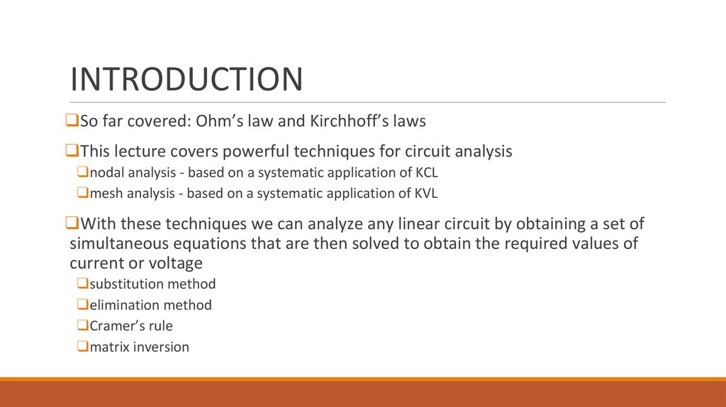
INTRODUCTION❑So far covered: Ohm’s law and Kirchhoff’s laws
❑This lecture covers powerful techniques for circuit analysis
❑nodal analysis - based on a systematic application of KCL
❑mesh analysis - based on a systematic application of KVL
❑With these techniques we can analyze any linear circuit by obtaining a set of
simultaneous equations that are then solved to obtain the required values of
current or voltage
❑substitution method
❑elimination method
❑Cramer’s rule
❑matrix inversion
3.
commonground
ground
chassis
ground
Nodal Analysis
❑In nodal analysis, we are interested in finding the node voltages by applying KCL
1. Select a node as the reference node, assign voltages V1, V2, …, Vn-1 to the remaining nodes, the voltages are referenced
with respect to the reference node
2. Apply KCL to each of the nonreference nodes, use Ohm’s law to express the branch currents in terms of node voltages.
3. Solve the resulting simultaneous equations to obtain the unknown node voltages
❑ The reference node is commonly called the ground since it is assumed to have zero potential
4.
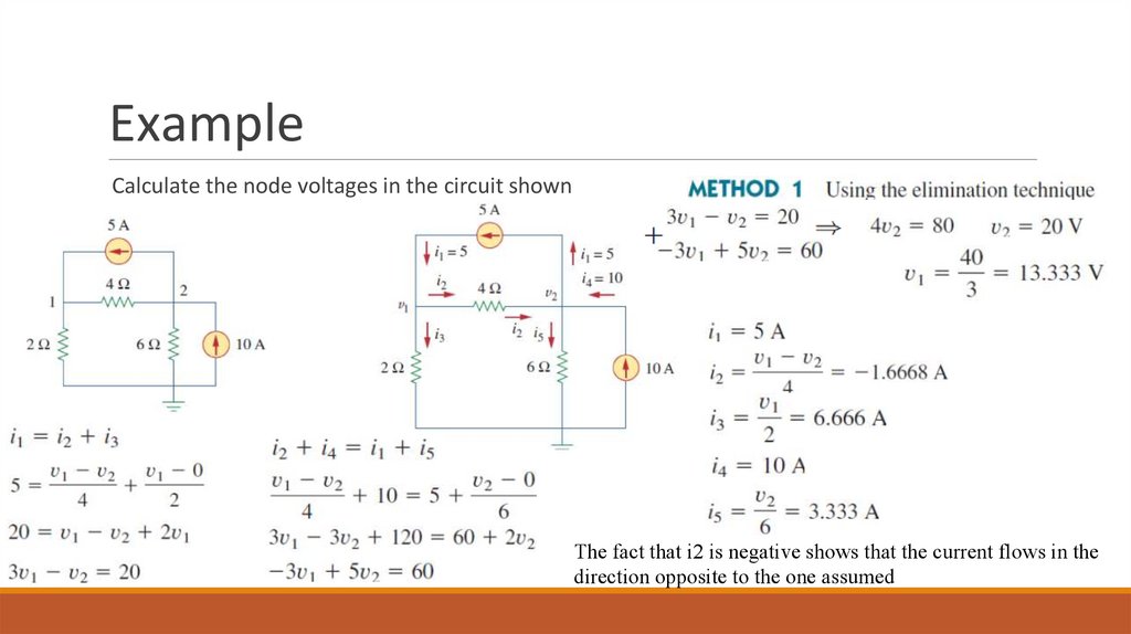
ExampleCalculate the node voltages in the circuit shown
The fact that i2 is negative shows that the current flows in the
direction opposite to the one assumed
5.
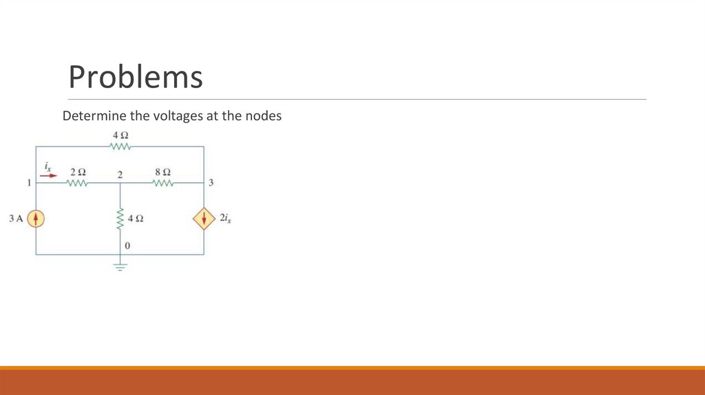
ProblemsDetermine the voltages at the nodes
6.
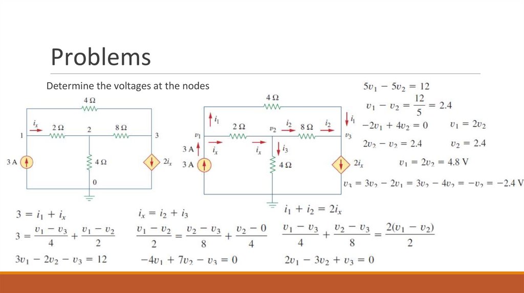
ProblemsDetermine the voltages at the nodes
7.
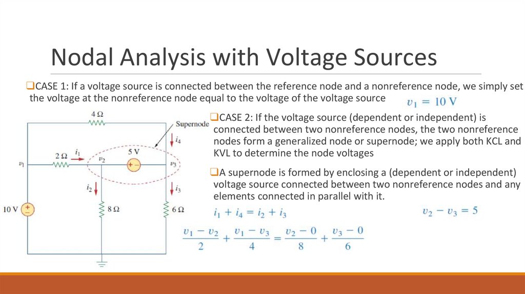
Nodal Analysis with Voltage Sources❑CASE 1: If a voltage source is connected between the reference node and a nonreference node, we simply set
the voltage at the nonreference node equal to the voltage of the voltage source
❑CASE 2: If the voltage source (dependent or independent) is
connected between two nonreference nodes, the two nonreference
nodes form a generalized node or supernode; we apply both KCL and
KVL to determine the node voltages
❑A supernode is formed by enclosing a (dependent or independent)
voltage source connected between two nonreference nodes and any
elements connected in parallel with it.
8.
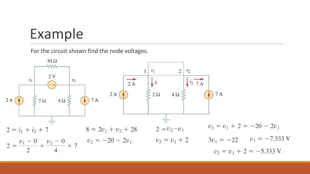
ExampleFor the circuit shown find the node voltages.
9.
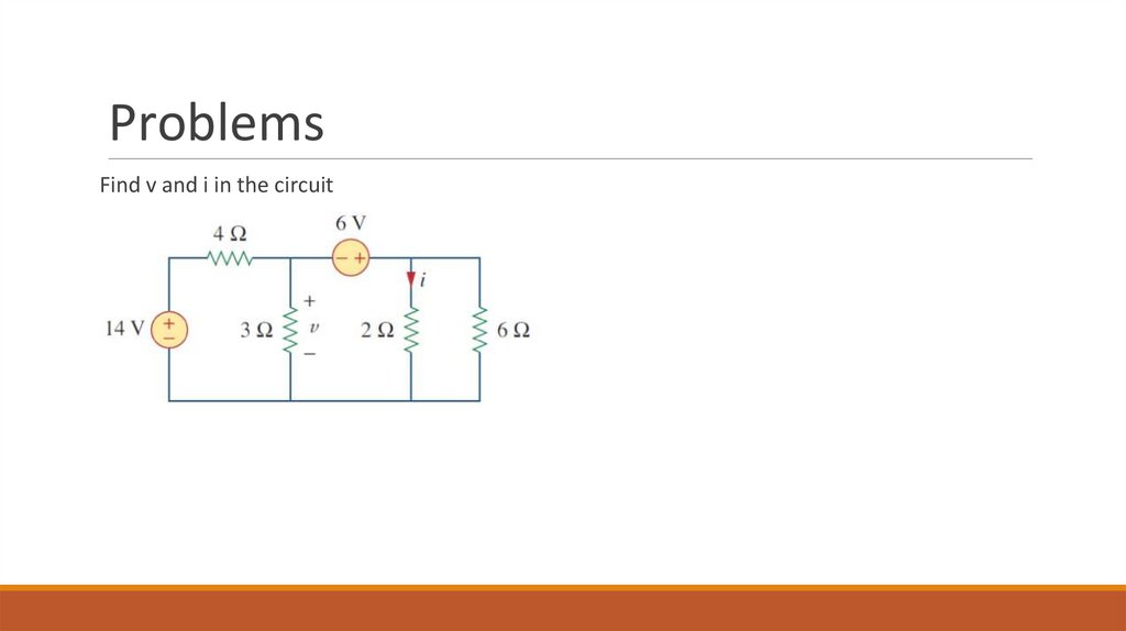
ProblemsFind v and i in the circuit
10.
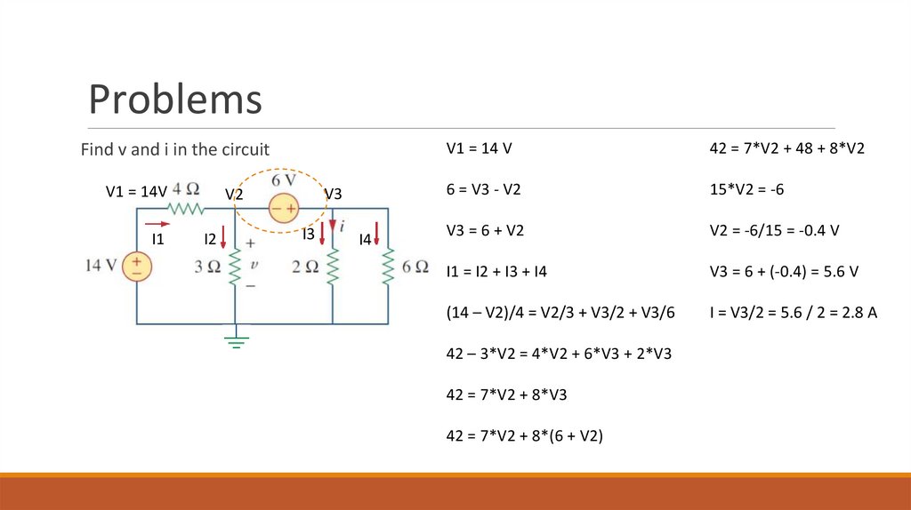
ProblemsFind v and i in the circuit
V1 = 14V
I1
V3
V2
I2
I3
I4
V1 = 14 V
42 = 7*V2 + 48 + 8*V2
6 = V3 - V2
15*V2 = -6
V3 = 6 + V2
V2 = -6/15 = -0.4 V
I1 = I2 + I3 + I4
V3 = 6 + (-0.4) = 5.6 V
(14 – V2)/4 = V2/3 + V3/2 + V3/6
I = V3/2 = 5.6 / 2 = 2.8 A
42 – 3*V2 = 4*V2 + 6*V3 + 2*V3
42 = 7*V2 + 8*V3
42 = 7*V2 + 8*(6 + V2)
11.
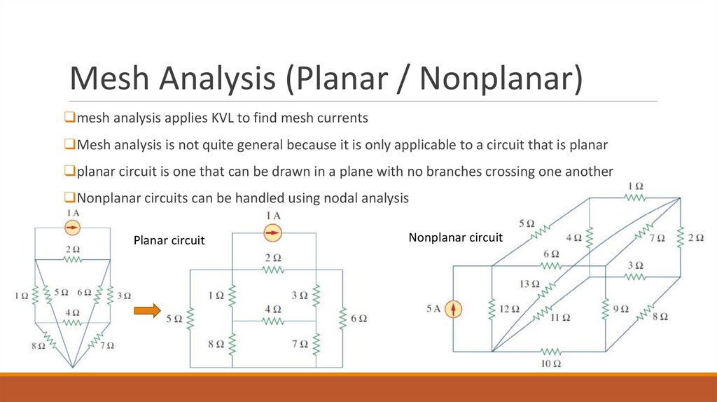
Mesh Analysis (Planar / Nonplanar)❑mesh analysis applies KVL to find mesh currents
❑Mesh analysis is not quite general because it is only applicable to a circuit that is planar
❑planar circuit is one that can be drawn in a plane with no branches crossing one another
❑Nonplanar circuits can be handled using nodal analysis
Planar circuit
Nonplanar circuit
12.
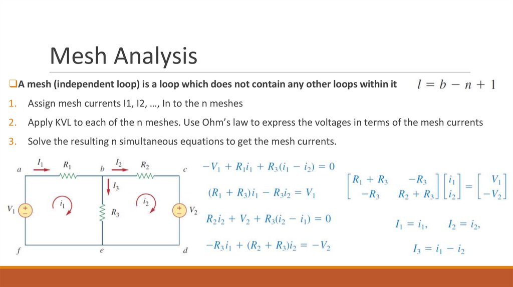
Mesh Analysis❑A mesh (independent loop) is a loop which does not contain any other loops within it
1.
Assign mesh currents I1, I2, …, In to the n meshes
2.
Apply KVL to each of the n meshes. Use Ohm’s law to express the voltages in terms of the mesh currents
3.
Solve the resulting n simultaneous equations to get the mesh currents.
13.
ExampleFor the circuit, find the branch currents using mesh analysis
14.
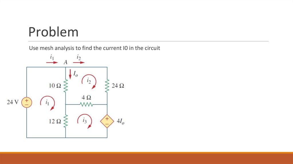
ProblemUse mesh analysis to find the current I0 in the circuit
15.
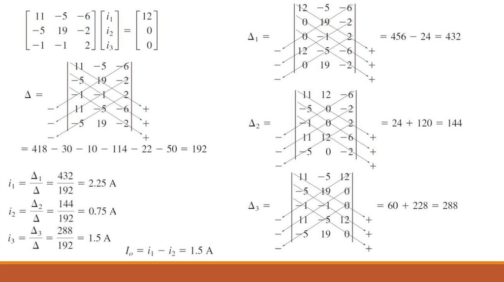
ProblemUse mesh analysis to find the current I0 in the circuit
16.
17.
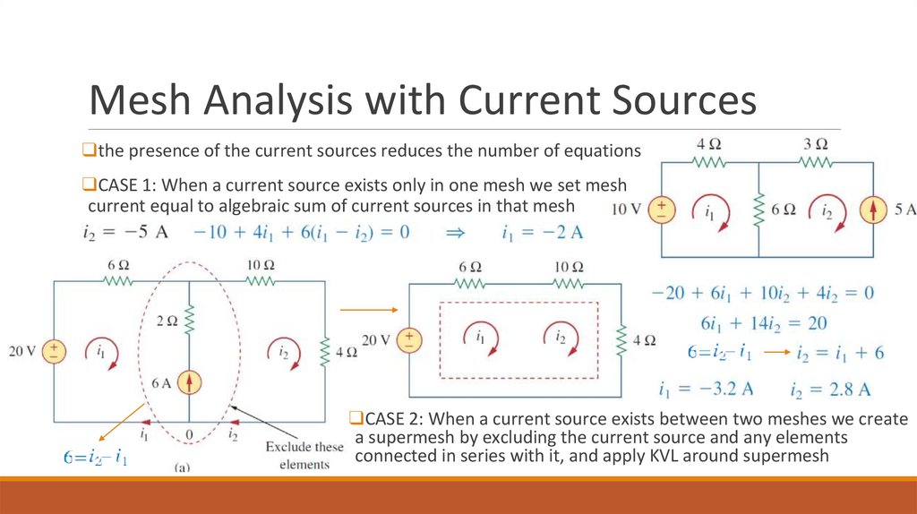
Mesh Analysis with Current Sources❑the presence of the current sources reduces the number of equations
❑CASE 1: When a current source exists only in one mesh we set mesh
current equal to algebraic sum of current sources in that mesh
❑CASE 2: When a current source exists between two meshes we create
a supermesh by excluding the current source and any elements
connected in series with it, and apply KVL around supermesh
18.
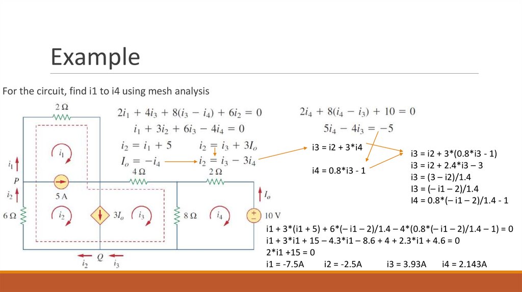
ExampleFor the circuit, find i1 to i4 using mesh analysis
i3 = i2 + 3*i4
i4 = 0.8*i3 - 1
i3 = i2 + 3*(0.8*i3 - 1)
i3 = i2 + 2.4*i3 – 3
i3 = (3 – i2)/1.4
I3 = (– i1 – 2)/1.4
I4 = 0.8*(– i1 – 2)/1.4 - 1
i1 + 3*(i1 + 5) + 6*(– i1 – 2)/1.4 – 4*(0.8*(– i1 – 2)/1.4 – 1) = 0
i1 + 3*i1 + 15 – 4.3*i1 – 8.6 + 4 + 2.3*i1 + 4.6 = 0
2*i1 +15 = 0
i1 = -7.5A
i2 = -2.5A
i3 = 3.93A
i4 = 2.143A
19.
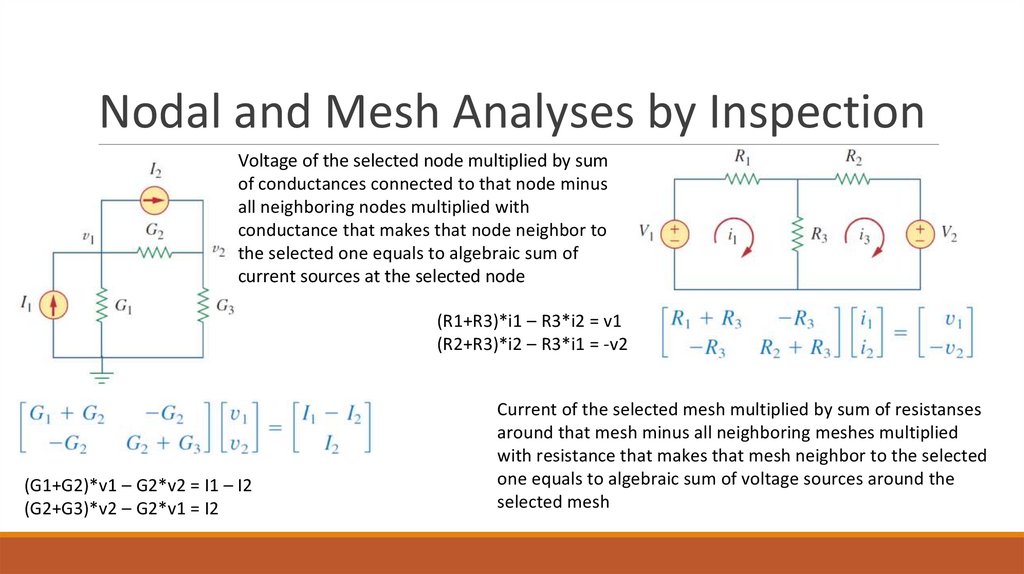
Nodal and Mesh Analyses by InspectionVoltage of the selected node multiplied by sum
of conductances connected to that node minus
all neighboring nodes multiplied with
conductance that makes that node neighbor to
the selected one equals to algebraic sum of
current sources at the selected node
(R1+R3)*i1 – R3*i2 = v1
(R2+R3)*i2 – R3*i1 = -v2
(G1+G2)*v1 – G2*v2 = I1 – I2
(G2+G3)*v2 – G2*v1 = I2
Current of the selected mesh multiplied by sum of resistanses
around that mesh minus all neighboring meshes multiplied
with resistance that makes that mesh neighbor to the selected
one equals to algebraic sum of voltage sources around the
selected mesh
20.
Nodal Versus Mesh Analysis❑first factor is the nature of the particular network
❑Networks that contain many series-connected elements, voltage sources, or supermeshes are more
suitable for mesh analysis
❑whereas networks with parallel-connected elements, current sources, or supernodes are more suitable
for nodal analysis
❑circuit with fewer nodes than meshes is better analyzed using nodal analysis
❑circuit with fewer meshes than nodes is better analyzed using mesh analysis
❑second factor is the information required
❑If node voltages are required, it may be better to apply nodal analysis
❑If branch or mesh currents are required, it may be better to use mesh analysis
21.
Home WorkFrom book Fundamentals of Electric Circuits (FIFTH EDITION) by Charles K. Alexander and
Matthew N. O. Sadiku solve:
Chapter 3, Problems section (pages 114-124):
Problems – 3.1, 3.2, 3.10, 3.11, 3.15, 3.16, 3.33, 3.36, 3.41, 3.44, 3.45, 3.49, 3.51