


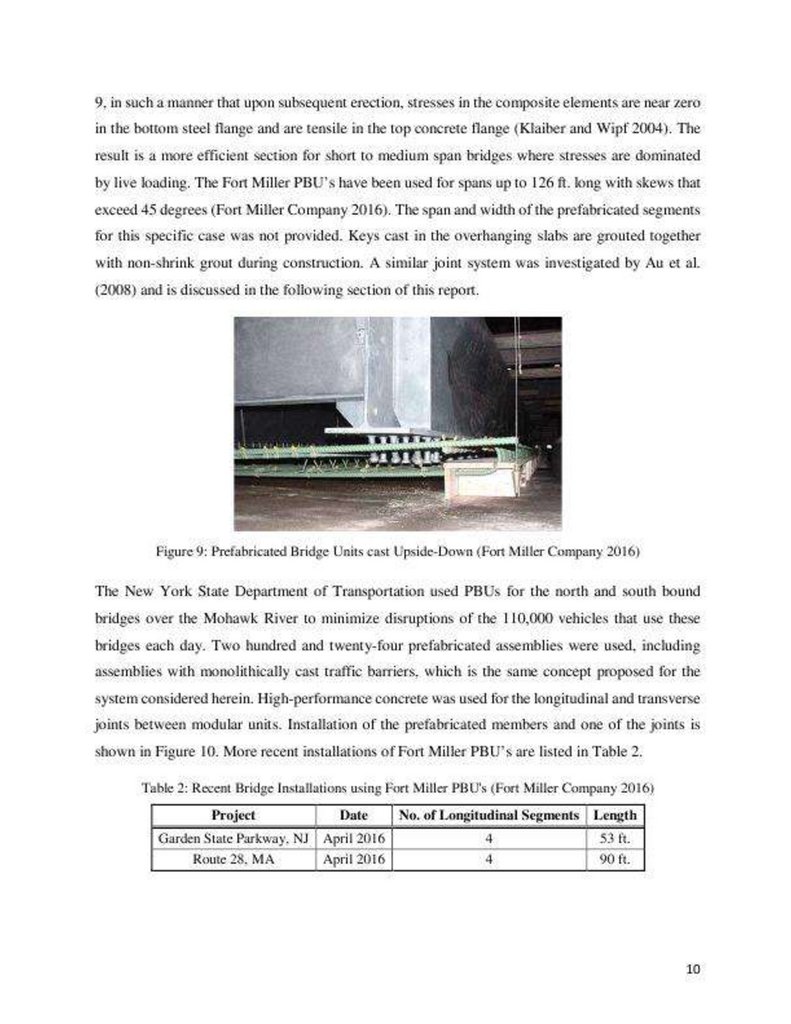

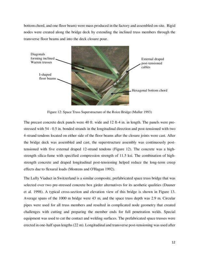


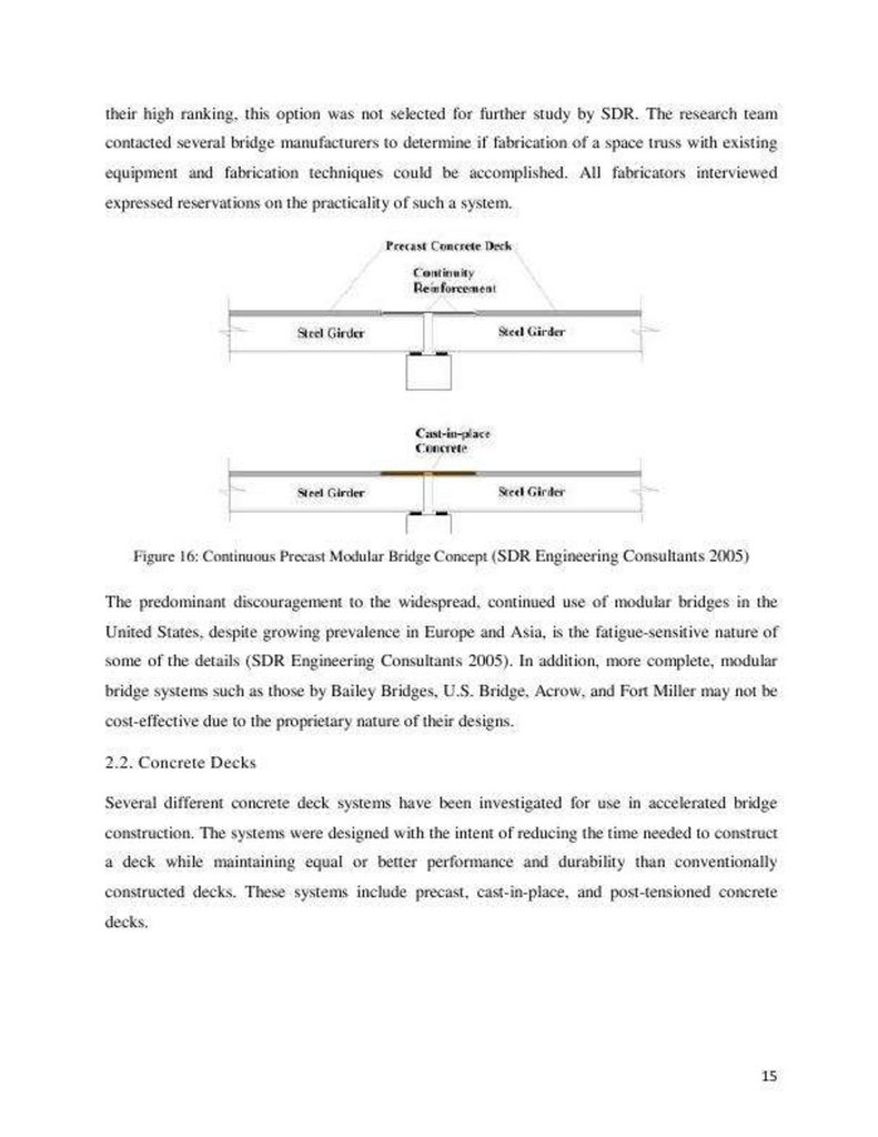


 Строительство
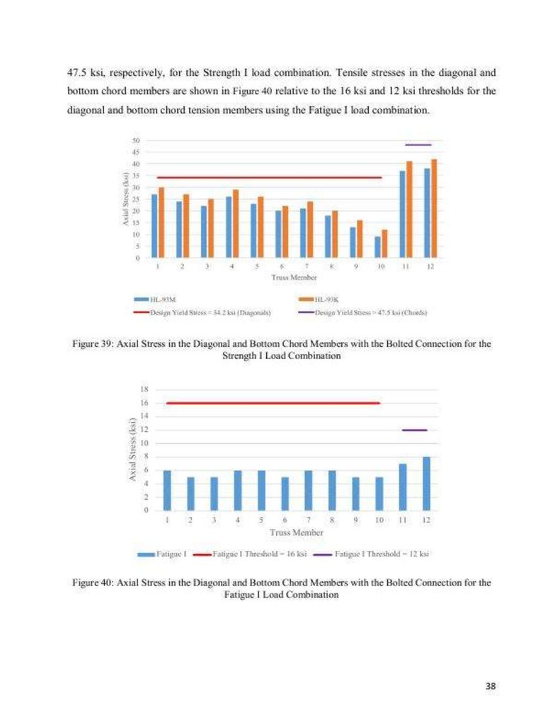
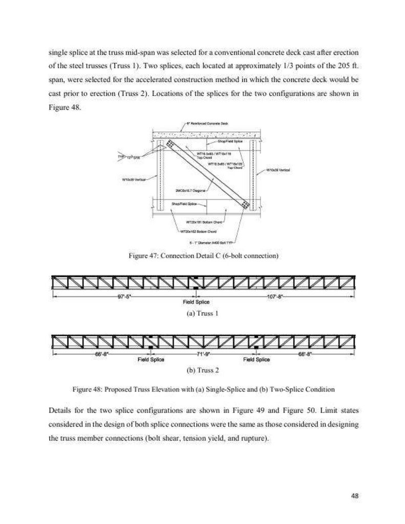
Похожие презентации:


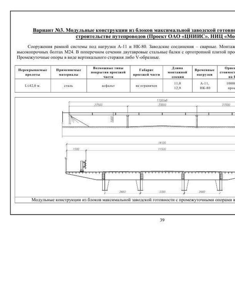
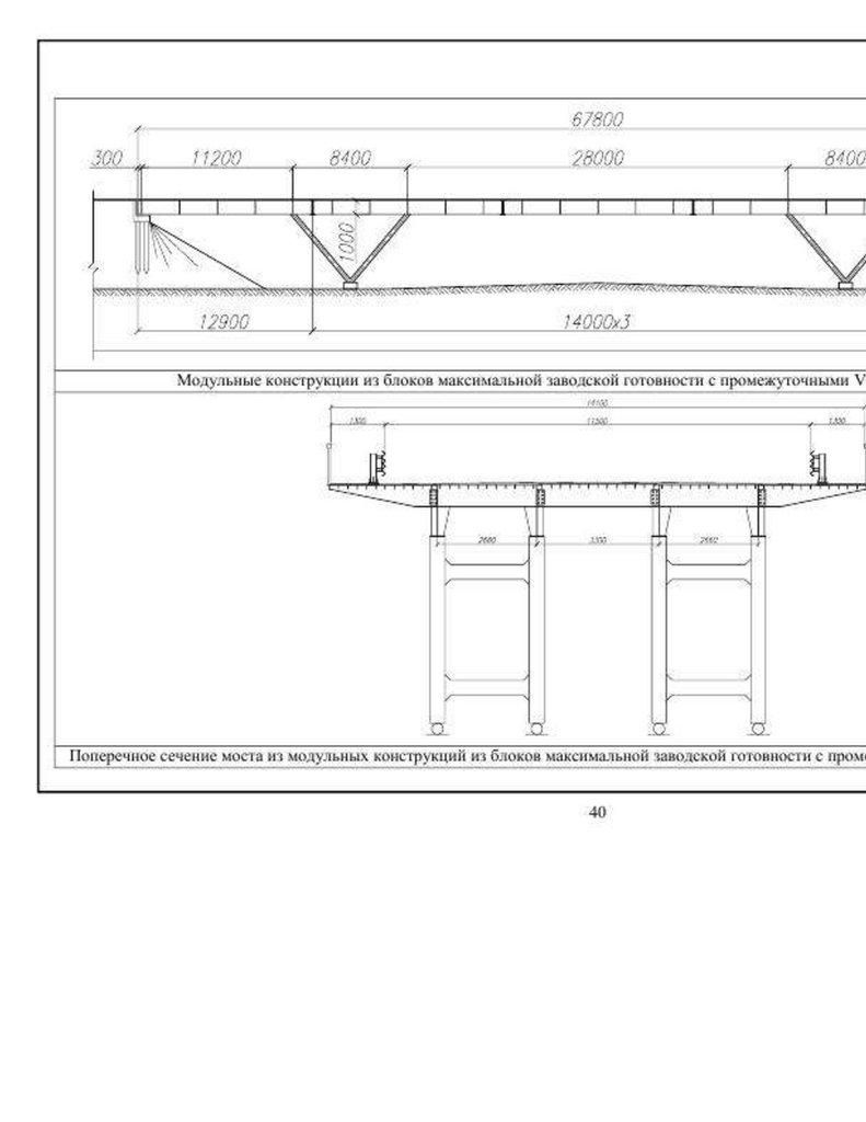
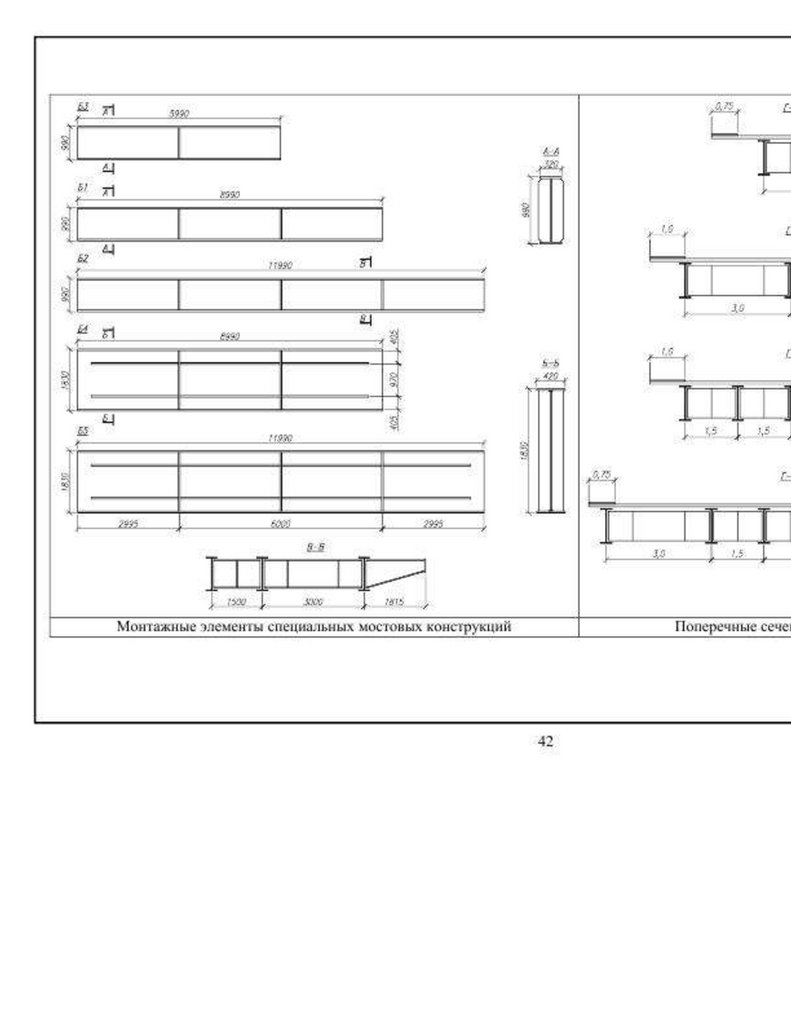
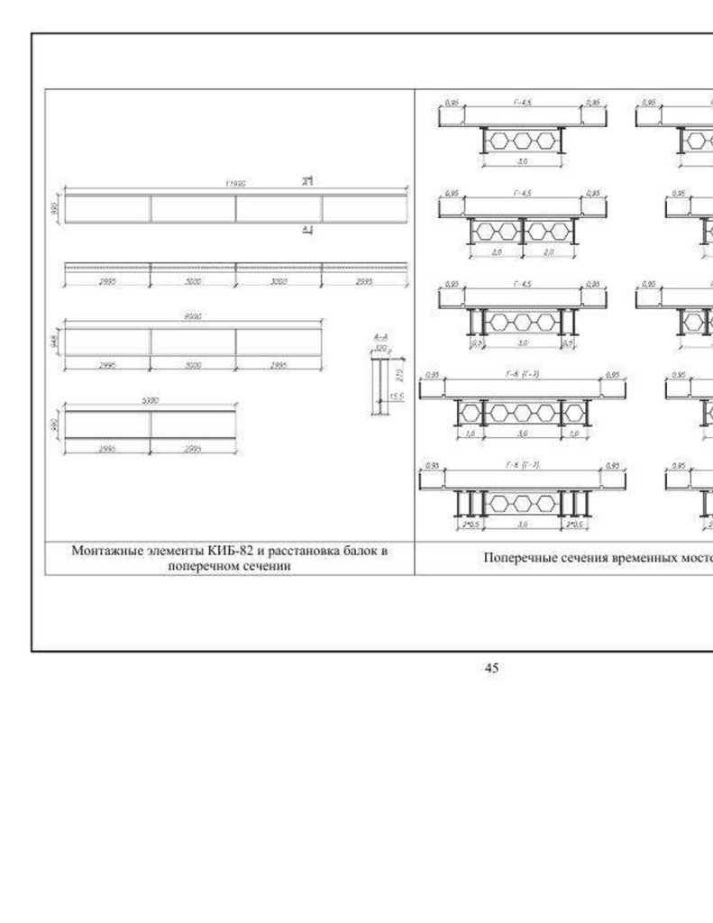
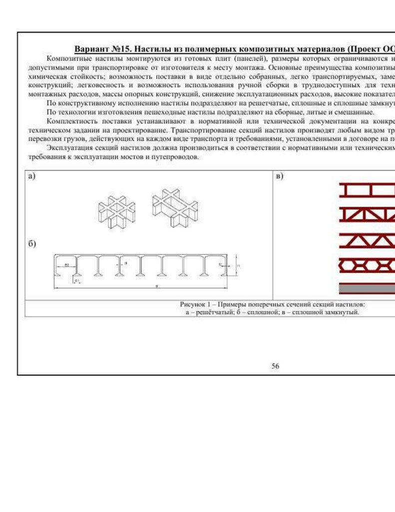
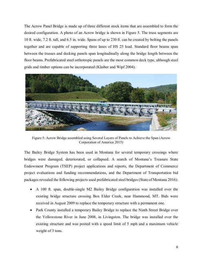
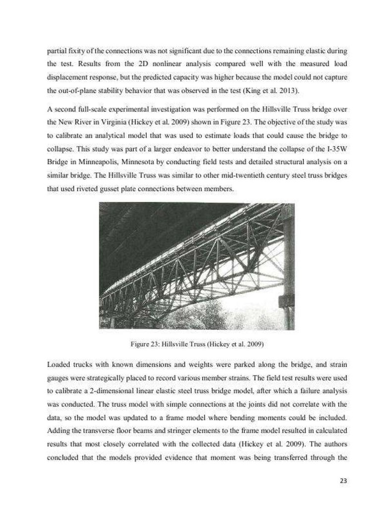
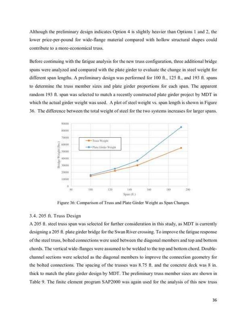
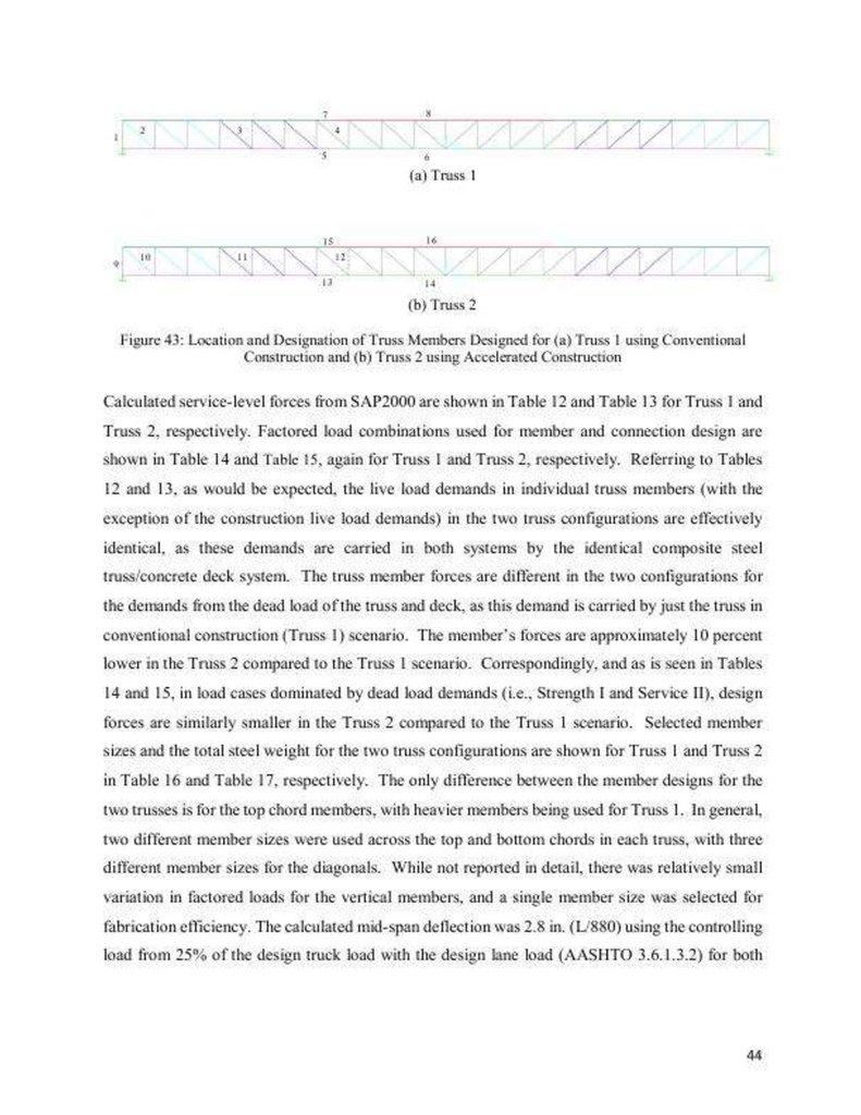
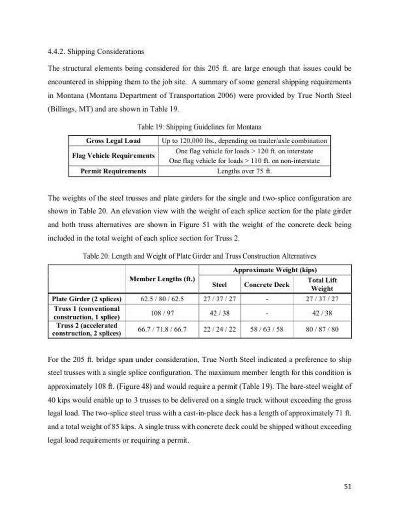
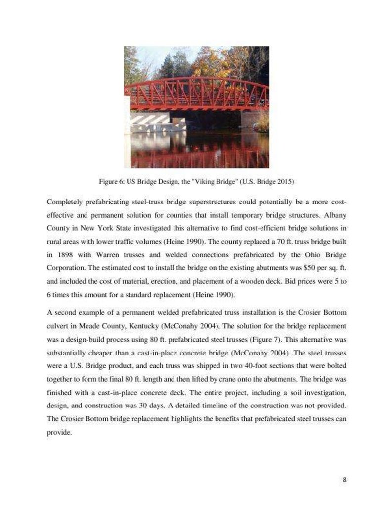
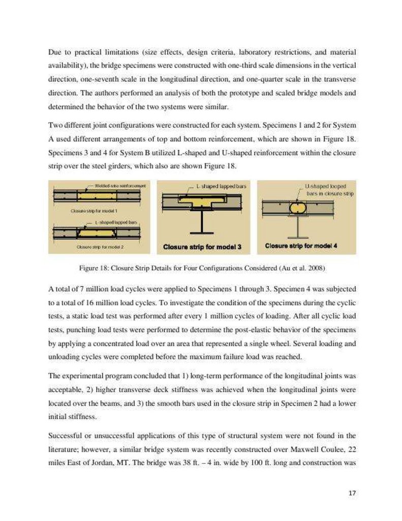
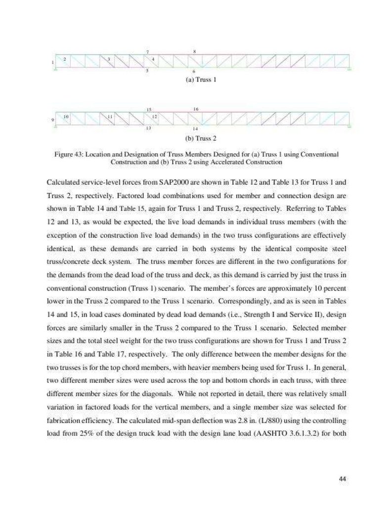
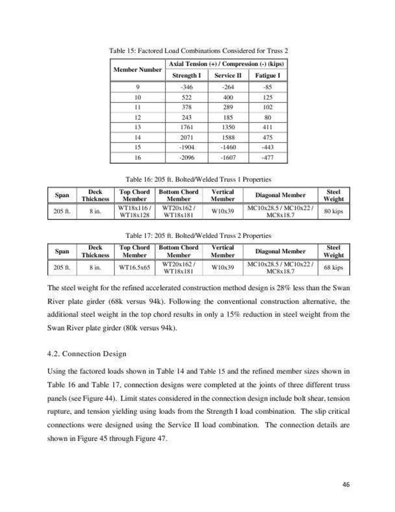
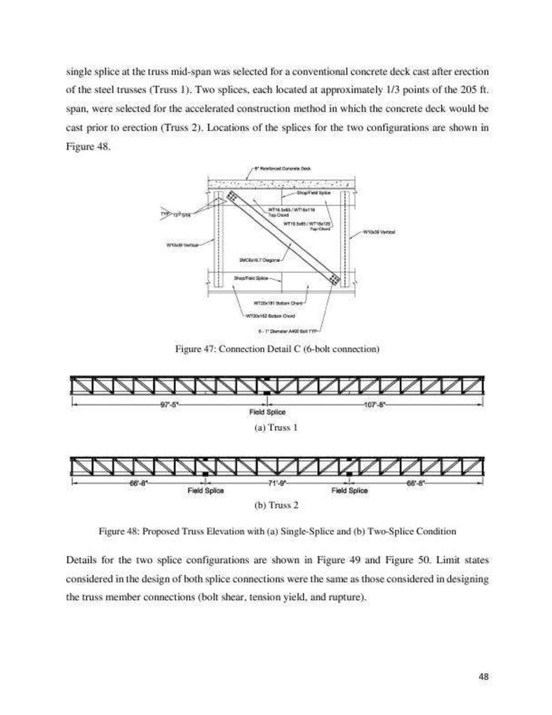
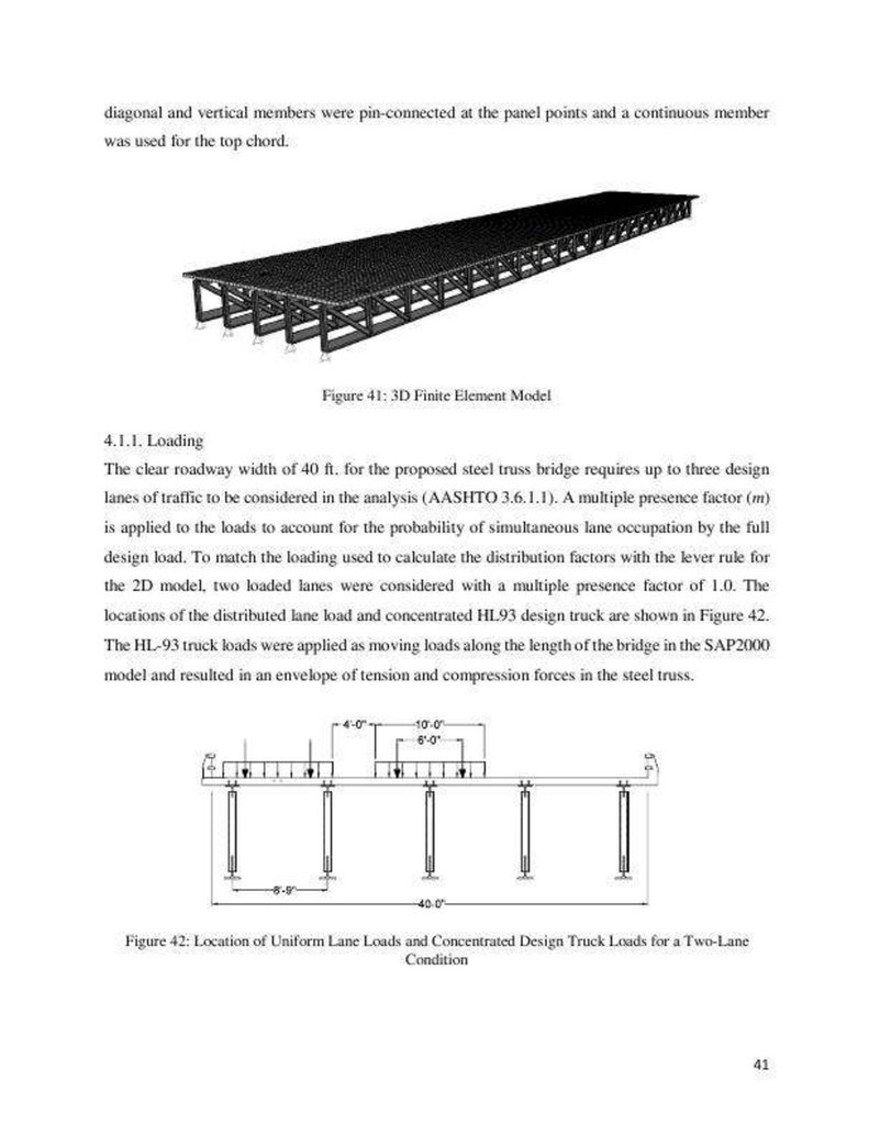
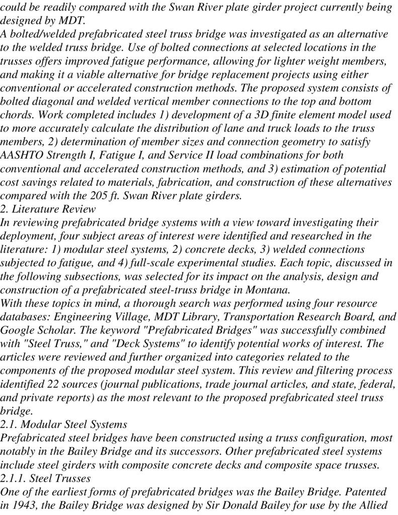
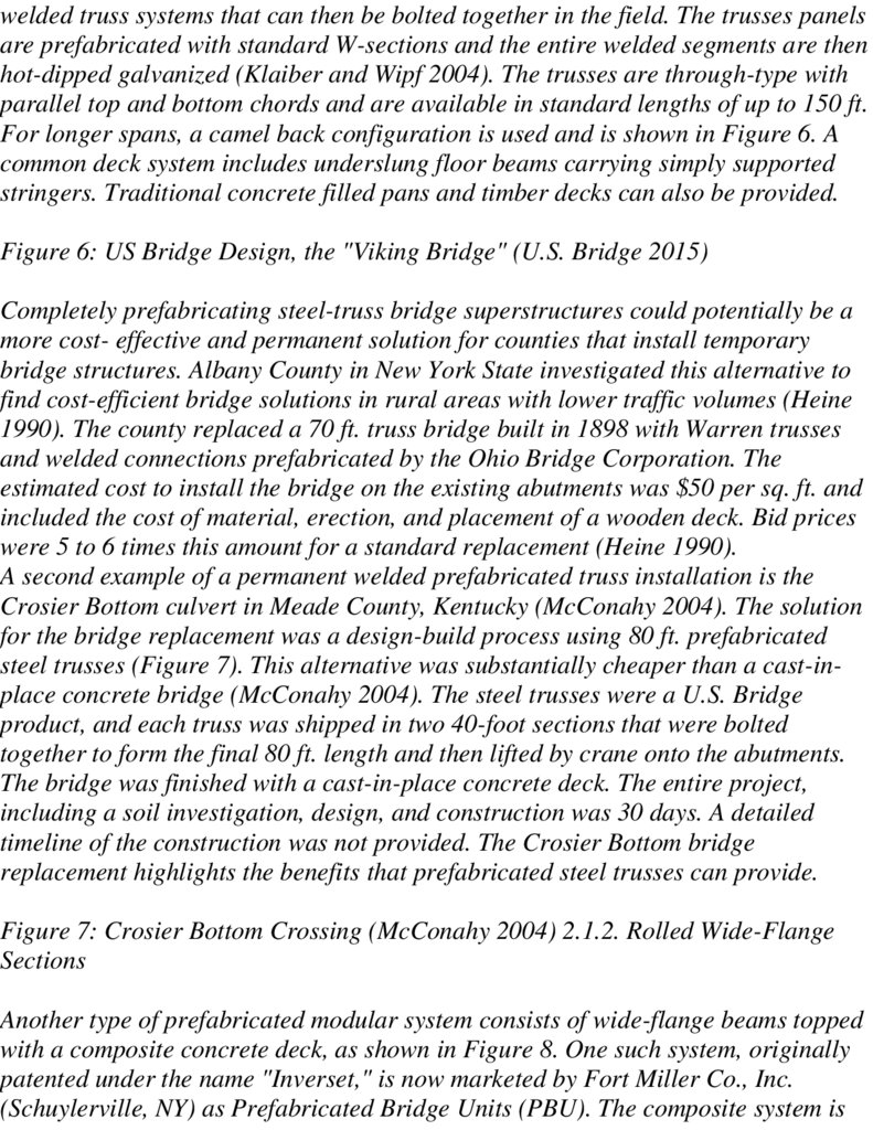
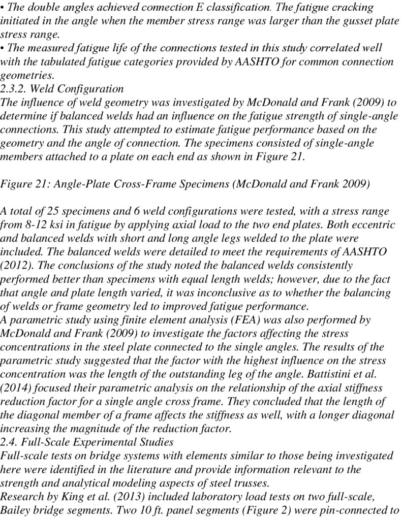
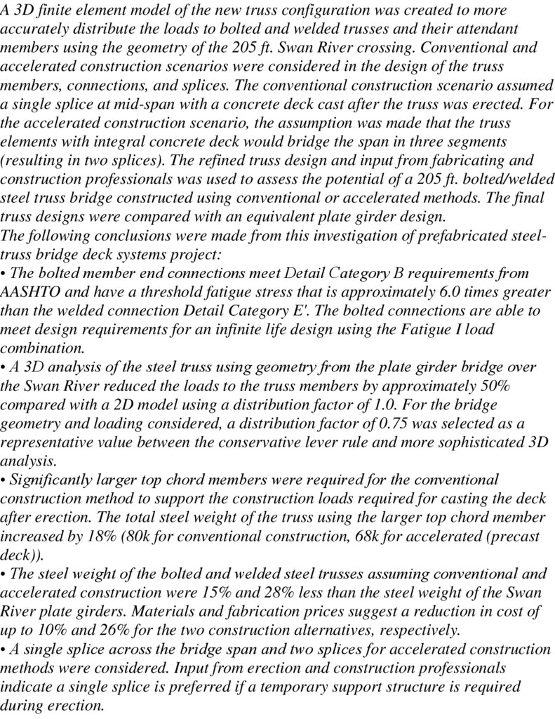
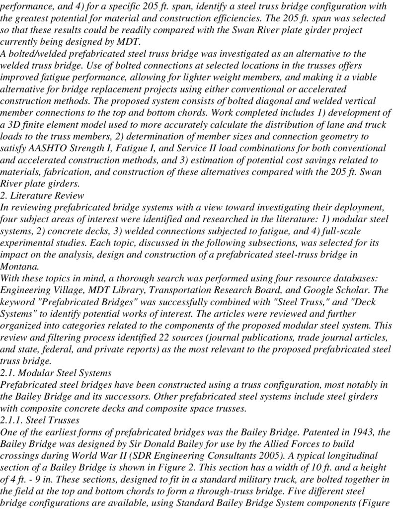
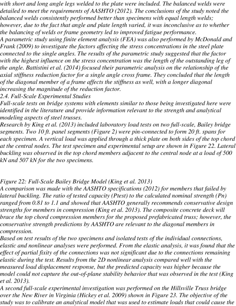
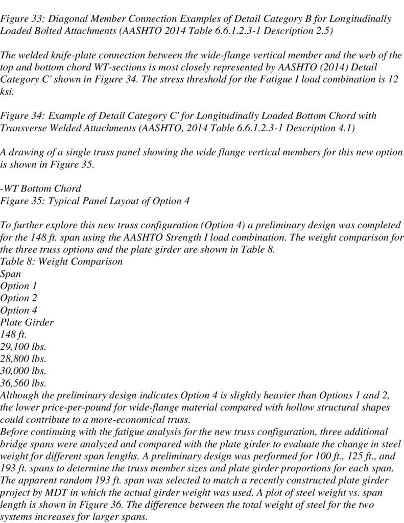
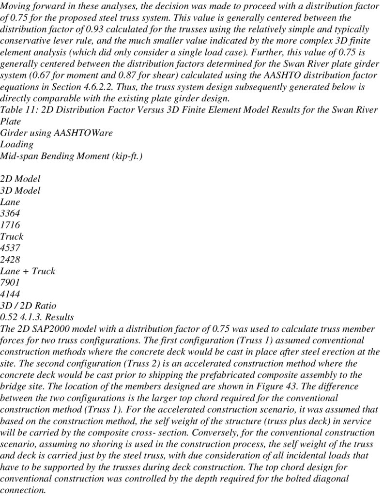
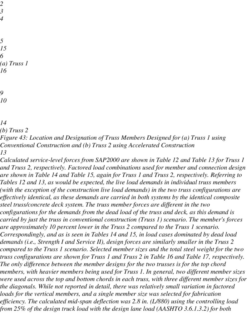
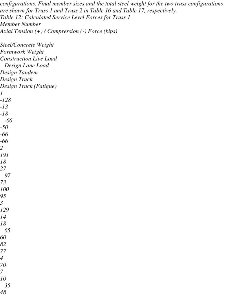
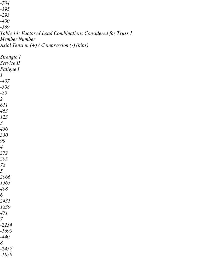
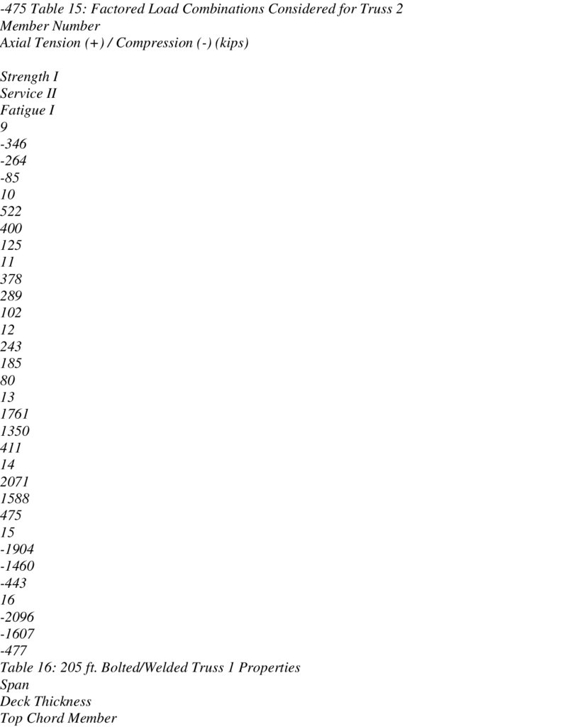
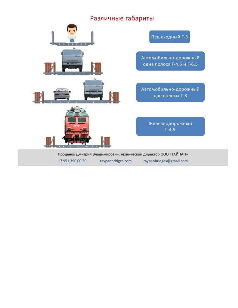
Применения быстро возводимых мостов и переправ из стальных конструкций покрытий производственных здании пролетами 18, 24 и 30 м
1.
ФОНДА ПОДДЕРЖКИ И РАЗВИТИЯ СЕЙСМОСТОЙКОГО СТРОИТЕЛЬСТВА "ЗАЩИТА И БЕЗОПАСНОСТЬ ГДля научно-практическая конференция «Интеллектуальные технологии на
и в гражданском строительстве» (Smart technologies in transport and civil eng
Внимание! Срок приема статей в журналы, индексируемые SCOPUS, продлен до
Индексация в SCOPUS будет 2023 годом!
[email protected]
Ежегодно в апреле в Петербургском государственном университете путей сообщ
Александра I проводится Научно-практическая конференция «Интеллектуальные
2.
на транспорте и в гражданском строительстве».Конференция проводится в заочном формате.
Основные направления Конференции:
Развитие высокоскоростного железнодорожного сообщения и магнитолевит
технологий;
Безопасная транспортная экосистема магистральной инфраструктуры;
Развитие объектов транспортной инфраструктуры в Арктической зоне Росси
Цифровая экосистема интеллектуальных приоритетов для транспорта и логи
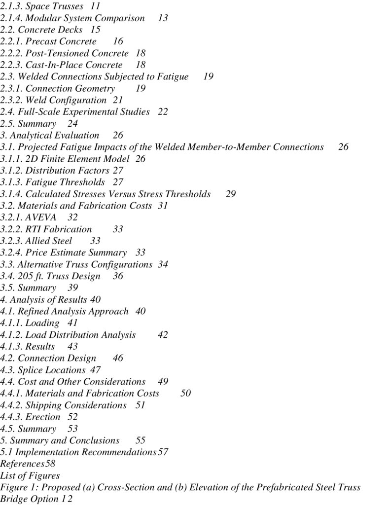
ОРГАН ПО СЕРТИФИКАЦИИ: ФГБОУ СПб ГАСУ № RA.RU.21 СТ39 от 27.05.2015, 190005, СПб, 2-я Крас
организация «Сейсмофонд» при СПб ГАСУ ОГРН: 1022000000824, т/ф (812) 694-78-10, (996)[email protected] (аттестат № RA.RU.21СТ39, выдан 27.05.2015)
Испытательного центра СПб ГАСУ, аккредитован Федеральной службой по
аккредитации (аттестат № RA.RU.21СТ39, выдан 27.05.2015), организация
"Сейсмофонд" при СПб ГАСУ, ОГРН: 1022000000824 т/ф (812) 694-78-10, 190005,
СПб, 2-я Красноармейская ул д 4 ФГБОУ СПб ГАСУ № RA.RU.21СТ39 от 27.05.2015,
190005, СПб, 2-я Красноармейская ул. д 4, Организация «Сейсмофонд» при СПб ГАСУБ, ИНН:
2014000780 [email protected] [email protected] [email protected]
[email protected] [email protected] (911) 175-84-65, (996) 798-26-54, (921) 962-67-78
3.
олное наименованиеокращенное наименование
ОГРН
ИНН
ФОНДА ПОДДЕРЖКИ И РАЗВИТИЯ СЕЙ
И БЕЗОПАСНОСТЬ ГОРОДОВ" "СЕЙСМО
Организация «СЕЙСМОФО
1022000000824
2014000780
4.
ППЮридический адрес
201401001
364024, г.Грозный, ул. им. С.Ш. Лорсанова, д
190005, СПб, 2-я Красноармейская у
1022000000824
Фактический адрес
елефон и факс
резидент
т/ф (812) 694-78-10 c694
Мажиев Хасан Нажоевич
21.12 Деятельность проф
ОКВЭД
ОКПО
ОКАТО
азвание банка СБЕР 2202 2006 4085 5233
СБЕР № 40817810455030402987
45270815
96401364
Счет получателя
Счет получателя СБЕР № 4081
асчетный счет
ИК
орреспондентский счет
40817810555031236845
044030653
30101810500000000653
ttp://188.254.71.82/rao_rf_pub/?show=view&id_object=DCB44608D54849B2A27CFEFEBEF970D4
идетельства, аттестаты и ккредитация. Подробнее в zip архиве на сайте : seismofond.ru
[email protected]
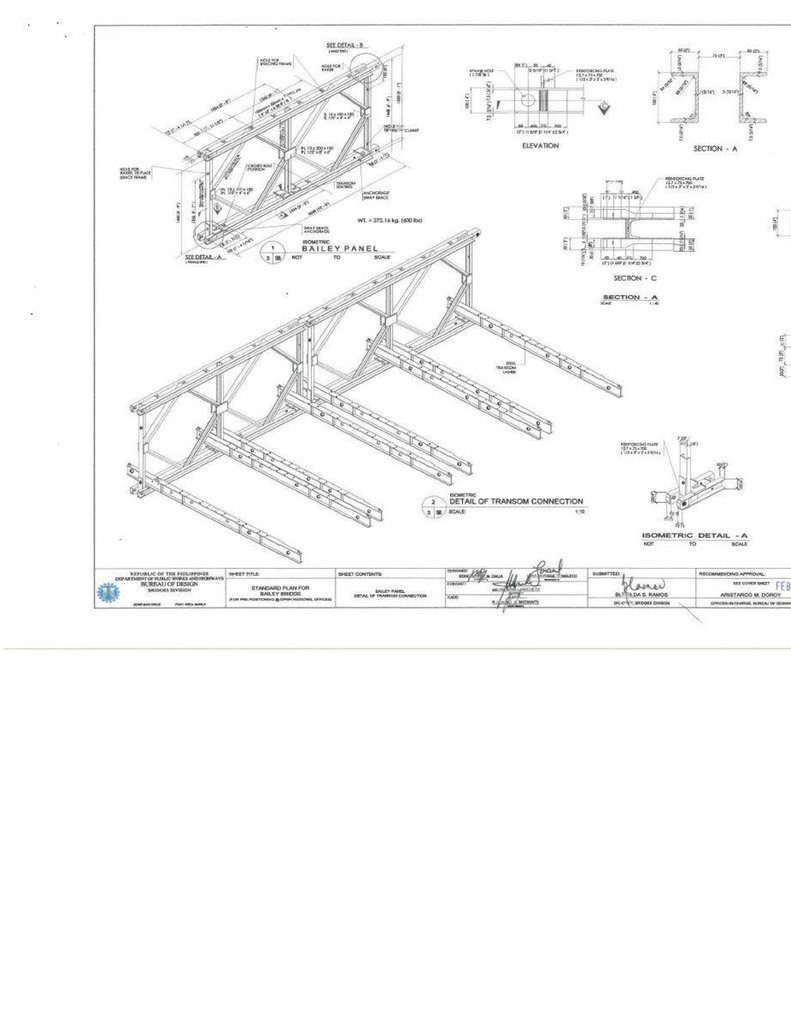
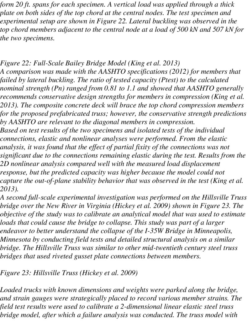
ПРИМЕНЕНИЯ БЫСТРО ВОЗВОДИМЫХ МОСТОВ И
ПЕРЕПРАВ из стальных конструкций покрытий
производственных здании пролетами 18, 24 и 30 м с
применением замкнутых гнутосварных профилей
прямоугольного сечения типа «Молодечно» (серия 1.460.314 ГПИ «Ленпроектстальконструкция» ) для системы
несущих элементов и элементов проезжей части
армейского сборно-разборного пролетного надвижного
строения железнодорожного моста, с быстросъемными
упругопластичными компенсаторам, гасителем
вибрационных напряжений от динамических нагрузок от
прохождения гусеничной груженной военной техники (
Т-72 весит 80 тонн ) с боеприпасами , со сдвиговой
фрикционно-демпфирующей жесткостью с
5.
использованием и учетом опыта наших х партеров изблока НАТО, США, Канады, Великобритании Смотри
приложение на английском языке
Выводы Перспективы применения быстровозводимых
мостов и переправ очевидны. Не имея хорошей
методической, научной, технической и практической
базы, задачи по быстрому временному восстановлению
мостовых переходов будут невыполнимы. Это приведет к
предсказуемым потерям Русское армии при переправе
через реку Днепр
Заключение по использованию упругопластического сдвигового
компенсатора гасителя сдвиговых напряжений для быстро
собираемых на антисейсмических фрикционно-подвижных
соединениях для сборно–разборного железнодорожного
армейского моста
1. Штыревые монтажные соединения секций разборного
пролетного строения временного моста позволяют существенно
ускорить процесс возведения и последующей разборки
конструкций, однако при этом являются причиной увеличения
общих деформаций пролетного строения, кроме
упругопластического сдвигового компенсатора, гасителя
сдвиговых напряжений для быстрособираемых на
антисейсмических фрикционно-подвижных соединениях для
6.
сборно–разборного железнодорожного армейского моста профдтн ПГУПС А.М.Уздина
2. Штатное двухпутное движение при двухсекционной
компоновке конструкций САРМ под современной автомобильной
нагрузкой не обеспечено прочностью как основного сечения секций,
так и элементов штыревых соединений, а использование
упругопластического сдвигового , компенсатора, гасителя
сдвиговых напряжений для быстро собираемых на
антисейсмических фрикционно-подвижных соединениях для
сборно–разборного железнодорожного армейского моста , все
напряжения снимает
3. В металле элементов штыревых соединений при
современной нагрузке накапливаются пластические деформации,
приводящие к выработке контактов «штырь-проушина» и
нарастанию общих деформаций (провисов), а упругопластический
сдвиговой компенсатор гаситель сдвиговых напряжений для
быстрособираемых на антисейсмических фрикционно-подвижных
соединениях для сборно–разборного железнодорожного
армейского моста гасить напряжения
4. Ускорению процесса износа элементов штыревых соединений
способствует многократная сборка-разборка пролетных
строений и их эксплуатация под интенсивной динамической
нагрузкой и не гасит сдвиговых напряжений для быстро
собираемых на антисейсмических фрикционно-подвижных
соединениях для сборно–разборного железнодорожного
армейского моста
7.
5. Образующийся провис пролетного строения создаетненормативное состояние продольного профиля ездового
полотна, снижающее пропускную способность и безопасность
движения, упругопластический сдвиговой компенсатор гаситель
сдвиговых напряжений для быстро собираемых на
антисейсмических фрикционно-подвижных соединениях для
сборно–разборного железнодорожного армейского моста
сдвиговый нагрузки «поглощает»
6. Изначально разборные конструкции САРМ проектировались под
нужды военного ведомства для мобильного и кратковременного
применения и штыревые монтажные соединения в полной мере
соответствуют такому назначению. При применении в
гражданском строительстве эту особенность следует
учитывать в разработке проектных решений, назначении и
соблюдении режима эксплуатации, например путем уменьшения
полос движения или увеличения числа секций в поперечной
компоновке, а использование сдвигового компенсатора,
гасителя сдвиговых напряжений для быстро собираемых на
антисейсмических фрикционно-подвижных соединениях для
сборно–разборного железнодорожного армейского моста
исключает обрушение железнодорожного моста
Дальнейшие исследования видятся в аналитическом обзоре
применяемых конструкций разборных мостов, разработке
8.
отвечающих современным требованиям проектных решенийвариантов поперечной и продольной компоновки пролетных
строений с использованием упругопластических , сдвиговых
компенсатор, которые гасят, сдвиговые напряжения для
быстро собираемых, на антисейсмических фрикционноподвижных соединениях , для отечественного сборно–разборного
железнодорожного армейского моста «Уздина»
Выводы Перспективы применения быстровозводимых мостов
и переправ очевидны. Не имея хорошей методической,
научной, технической и практической базы, задачи по
быстрому временному восстановлению мостовых переходов
будут невыполнимы. Это приведет к предсказуемым потерям
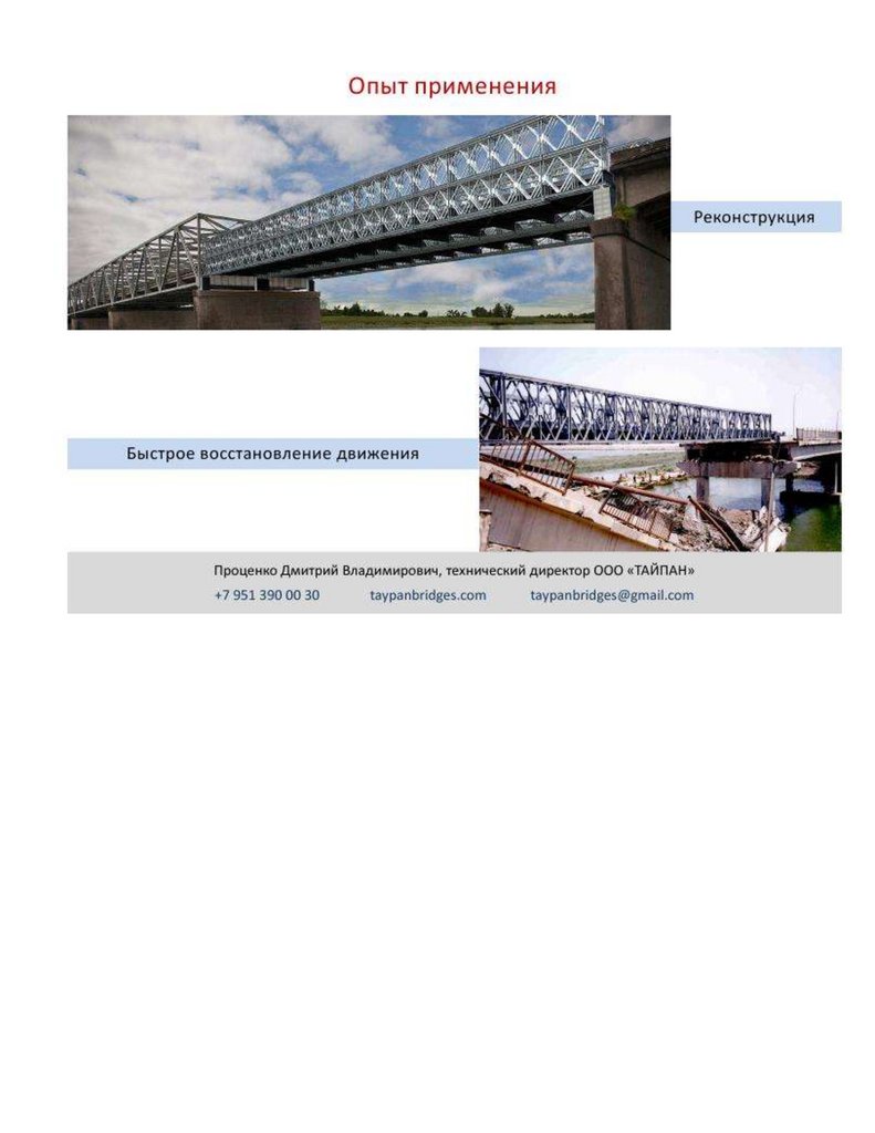
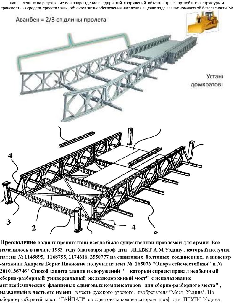
Преодоление водных препятствий всегда было существенной проблемой для армии. Все
изменилось в начале 1983 году благодаря проф дтн ЛИИЖТ А.М.Уздину , который получил
патент № 1143895, 1168755, 1174616, 2550777 на сдвиговых болтовых соединениях, а инженер механик Андреев Борис Иванович получил патент № 165076 "Опора сейсмостойкая" и №
2010136746 "Способ защита здания и сооружений ", который спроектировал необычный сборноразборный армейский универсальный железнодорожный мост" с использование
антисейсмических фланцевых сдвиговых компенсаторов, пластический сдвиговой компенсатор (
Сдвиговая прочность при действии поперечной силы СП 16.13330.2011, Прочностные проверки
SCAD Закон Гука ) для сборно-разборного моста" , названный в честь его имени в честь русского
ученого, изобретателя "Мост Уздина". Но сборно-разборный мост "ТАЙПАН" со сдвиговым
компенсатором проф дтн ПГУПС Уздина , пока на бумаге. Sborno-razborniy bistrosobiraemiy
universalniy most UZDINA PGUPS 453 str https://ppt-online.org/1162626
https://disk.yandex.ru/d/iCyG5b6MR568RA
Зато, западные партнеры из блока НАТО , уже внедрили похожие изобретения проф дтн ПГУПС
Уздина А М. по использованию сдвигового компенсатора под названием армейский Bailey bridge
при использовании сдвиговой нагрузки, по заявке на изобретение № 2022111669 от 27.04.2022
входящий ФИПС 024521 "Конструкция участка постоянного железобетонного моста неразрезной
системы" , № 2021134630 от 06.05.2022 "Фрикционно-демпфирующий компенсатор для
трубопроводов", а20210051 от 29 июля 2021 Минск "Спиральная сейсмоизолирующая опора с
9.
упругими демпферами сухого терния" . № а 20210217 от 23 сентября 2021, Минск " Фланцевоесоединение растянутых элементов трубопровода со скошенными торцами"
Однако, на переправе Северский Донец из выжило очень мало русский солдат. В Луганской области
при форсировании реки Северский Донец российская армия потеряла много военнослужащих
семьдесят четвёртой мотострелковой бригады из-за отсутствия на вооружение наплавных ложных
мостов , согласно изобретениям № 185336, № 77618. Об этом сообщил американский Институт
изучения войны. "11 мая украинская артиллерия с гаубиц М 777 уничтожила российские понтонные
мосты и плотно сконцентрированные вокруг них российские войска и технику, в результате чего, как
сообщается, погибло много русских солдат и было повреждено более 80 единиц техники», —
отмечается в публикации. По оценке института, войска РФ допустили значительные тактические
ошибки при попытке форсирования реки в районе Кременной, что привело к таким потерям. Ранее в
Институте изучения войны отмечали, что российские войска сосредотачиваются на битве за
Северодонецк, отказавшись от плана крупномасштабного окружения ВСУ и выхода на
административные границы Донецкой области https://disk.yandex.ru/i/3ncRcfqDyBToqg
Administratsiya Armeyskie mosti uprugoplasticheskim sdvigovoy jestkostyu 176 str
https://ppt-online.org/1235168
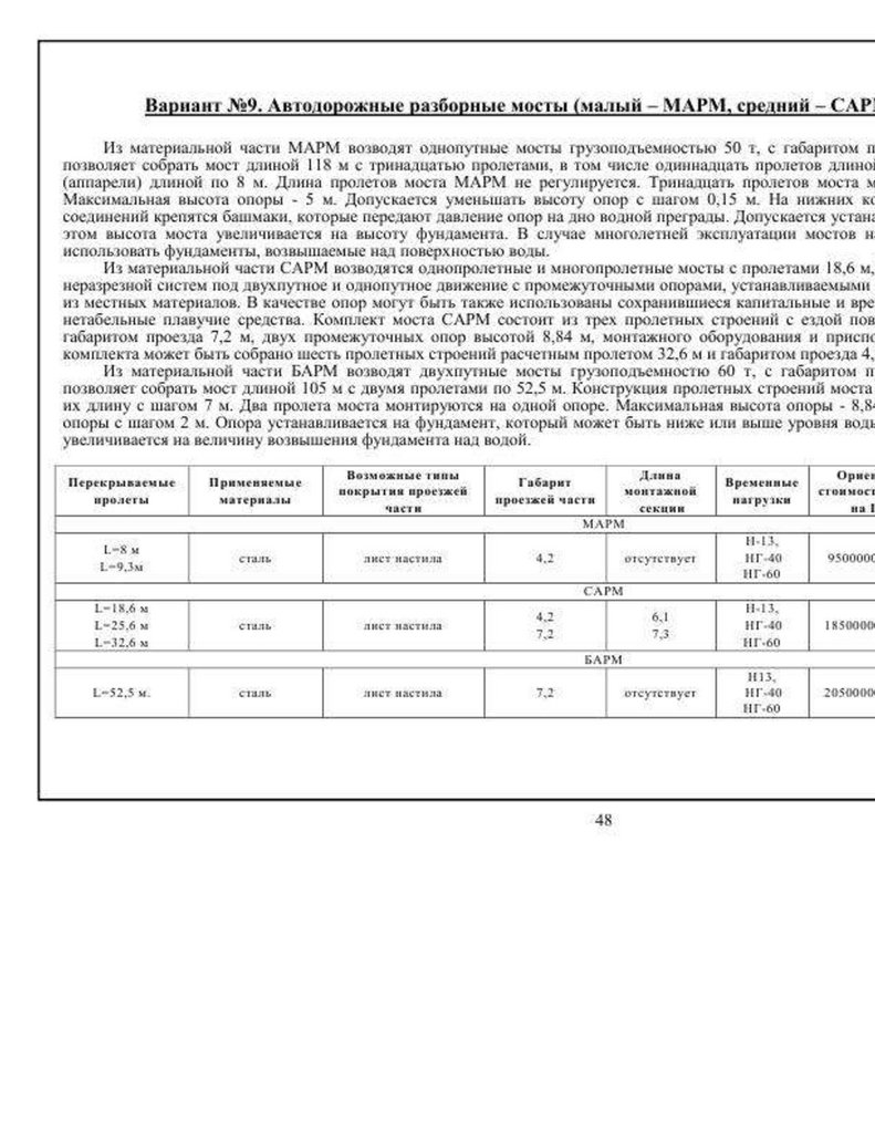
Среди прочих мостов , в том числе и современных разборных конструкций мостов,
особое место занимает средний автомобильный разборный мост (САРМ),
разработанный в 1968 г. и модернизированный в 1982 г. для нужд Минобороны СССР. В
процессе вывода накопленных на хранении комплектов САРМ в гражданский сектор
строительства выяснилась значительная востребованность этих конструкций,
обусловленная следующими их преимуществами: полная укомплектованность всеми
элементами моста, включая опоры; возможность перекрытия пролетов 18,6, 25,6,
32,6 м с габаритами ездового полотна 4,2 м при однопутном и 7,2 м при двухпутном
проезде. Паспортная грузоподъемность обозначена как 40 т при однопутном проезде
и 60 т при двухпутном проезде.
Так как по ряду геометрических и технических параметров конструкции САРМ не в
полной мере соответствуют требованиям современных норм для капитальных
мостов, то применение их ориентировано в основном как временных.
Следует отметить, что при незначительной доработке - постановке современных
ограждений и двухпутной поперечной компоновке секций для однополосного
движения можно добиться соответствия требуемым геометрическим параметрам
ездового полотна и общей грузоподъемности для мостов на дорогах общего
пользования IV и V технической категории.
10.
В статье рассматривается конструктивная особенность штыревых монтажныхсоединений секций разборного пролетного строения как фактор, определяющий
грузоподъемность, характер общих деформаций и в итоге влияющий на
транспортно- эксплуатационные характеристики мостового сооружения.
Целью настоящего исследования является анализ работы штыревых монтажных
соединений секций пролетного строения САРМ с оценкой напряженного состояния
элементов узла соединения. Новизной в рассмотрении вопроса полагаем оценку
прочности элементов штыревых соединений и ее влияние на общие деформации прогибы главных балок.
Ключевые слова: пролетное строение; нижний пояс; верхний пояс; штыревое
соединение; проушина; прочность; прогиб, методом оптимизации и идентификации
статических задач теории устойчивости надвижного армейского моста (жесткостью) при
действии проперченных сил в ПK SCAD СП 16.1330.2011. SCAD п.7.1.1 в механике деформируемых
сред и конструкций с учетом сдвиговой прочности при математическом моделировании.
Введение
Наряду с постоянными, капитальными мостами на автомобильных дорогах
общего пользования востребованы сооружения на дорогах временных, объездных,
внутрихозяйственных с приоритетом сборно-разборности и мобильности
конструкций надвижного армейского моста (жесткостью) при действии проперченных сил в ПK
SCAD СП 16.1330.2011. SCAD п.7.1.1 в механике деформируемых сред и конструкций с учетом
сдвиговой прочности при математическом моделировании методом оптимизации и
идентификации статических задач теории устойчивости надвижного армейского моста
(жесткостью) при действии проперченных сил в ПK SCAD СП 16.1330.2011. SCAD п.7.1.1 в механике
деформируемых сред и конструкций с учетом сдвиговой прочности при математическом
моделировании.
. Прокладка новых дорог, а также ремонты и реконструкции существующих
неизбежно сопровождаются временными мостами, первоначально пропускающими
движение основной магистрали или решающими технологические задачи строящихся
сооружений. Подобные сооружения могут быть пионерными в развитии
транспортных сетей регионов с решением освоения удаленных сырьевых районов.
11.
В книге А.В. Кручинкина «Сборно-разборные временные мосты» *1+ сборно-разборныемосты классифицированы как временные с меньшим, чем у постоянных мостов
сроком службы, обусловленным продолжительностью выполнения конкретных задач.
Так, для пропуска основного движения и обеспечения технологических нужд при
строительстве нового или ремонте (реконструкции) существующего моста срок
службы временного определен от нескольких месяцев до нескольких лет. Для
транспортного обеспечения лесоразработок, разработки и добычи полезных
ископаемых с ограниченными запасами временные мосты могут служить до 10-20
лет *1+. Временные мосты применяют также для обеспечения транспортного
сообщения сезонного характера и для разовых транспортных операций.
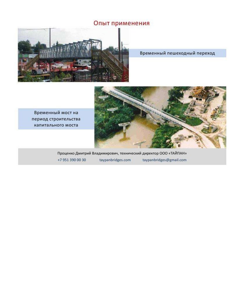
Особая роль отводится временным мостам в чрезвычайных ситуациях, когда
решающее значение имеют мобильность и быстрота возведения для срочного
восстановления прерванного движения транспорта.
В силу особенностей применения к временным мостам как отдельной ветви
мостостроения уделяется достаточно много внимания и, несмотря на развитие
сети дорог, повышение технического уровня и надежности постоянных сооружений,
задача совершенствования временных средств обеспечения переправ остается
актуальной *2+.
Что касается материала временных мостов, то традиционно применялась
древесина как широко распространенный и достаточно доступный природный
ресурс. В настоящее время сталь, конкурируя с железобетоном, активно расширяет
свое применение в сфере мостостроения становясь все более доступным и
обладающим лучшим показателем «прочность-масса» материалом. Давно
проявилась тенденция проектирования и строительства стальных пролетных
строений постоянных мостов даже средних и малых, особенно в удаленных
территориях с недостаточной транспортной доступностью и слабо развитой
инфраструктурой. Разумеется, для мобильных и быстровозводимых временных
мостов сталь - давно признанный и практически единственно возможный материал.
Конструктивное развитие временных мостов можно разделить на следующие
направления:
12.
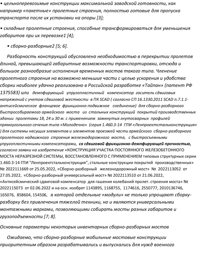
• цельноперевозимые конструкции максимальной заводской готовности, какнапример «пакетные» пролетные строения, полностью готовые для пропуска
транспорта после их установки на опоры *3+;
• складные пролетные строения, способные трансформироваться для уменьшения
габаритов при их перевозке1 *4+;
• сборно-разборные2 *5; 6+.
Разборность конструкций обусловлена необходимостью в перекрытии пролетов
длиной, превышающей габаритные возможности транспортировки, отсюда и
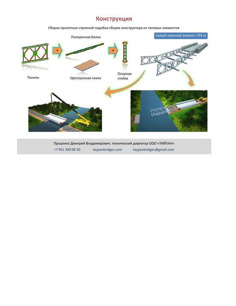
большое разнообразие исполнения временных мостов такого типа. Членение
пролетного строения на возможно меньшие части с целью ускорения и удобства
сборки наиболее удачно реализовано в Российской разработке «Тайпан» (патент РФ
1375583) или демпфирующий упругопластичный компенсатор гаситель сдвиговых
напряжений с учетом сдвиговой жесткости в ПК SCAD ( согласно СП 16.1330.2011 SCAD п.7.1.1антисейсмическое фланцевое фрикционно-подвижное соединение) для сборно-разборного
быстрособираемого армейского моста из стальных конструкций покрытий производственных
здании пролетами 18, 24 и 30 м. с применением замкнутых гнутосварных профилей
прямоугольного сечения типа «Молодечно» (серия 1.460.3-14 ГПИ «Ленпроектстальконструкция»
) для системы несущих элементов и элементов проезжей части армейского сборно-разборного
пролетного надвижного строения железнодорожного моста, с быстросъемными
упругопластичными компенсаторами, со сдвиговой фрикционно-демпфирующей прочностью,
согласно заявки на изобретение «КОНСТРУКЦИЯ УЧАСТКА ПОСТОЯННОГО ЖЕЛЕЗОБЕТОННОГО
МОСТА НЕРАЗРЕЗНОЙ СИСТЕМЫ, ВОССТАНОВЛЕННОГО С ПРИМЕНЕНИЕМ типовых структурных серии
1.460.3-14 ГПИ "Ленпроектстальконструкция", стальные конструкции покрытий производственных»
№ 2022111669 от 25.05.2022, «Сборно-разборный железнодорожный мост» № 2022113052 от
27.05.2022, «Сборно-разборный универсальный мост» № 2022113510 от 21.06.2022,
«Антисейсмический сдвиговой компенсатор для гашения колебаний пролет. строения моста» №
2022115073 от 02.06.2022 и на осн. изобрет 1143895, 1168755, 1174616, 2550777, 2010136746,
165076, 858604, 154506, в которой отдельные «модули» не только упрощают сборку-
разборку без привлечения тяжелой техники, но и являются универсальными
монтажными марками, позволяющими собирать мосты разных габаритов и
грузоподъемности *7; 8+.
Основные параметры некоторых инвентарных сборно-разборных мостов
Ожидаемо, что сборно-разборные мобильные мостовые конструкции
приоритетным образом разрабатывались и выпускались для нужд военного
13.
ведомства и с течением времени неизбежно попадали в гражданский сектормостостроения. Обзор некоторых подобных конструкций приведен в ссылке
ВЛИЯНИЕ МОНТАЖНЫХ СОЕДИНЕНИЙ СЕКЦИЙ РАЗБОРНОГО МОСТА НА ЕГО НАПРЯЖЕННО-ДЕФОРМИРОВАННОЕ СОСТОЯНИЕ
ТОМИЛОВ СЕРГЕЙ НИКОЛАЕВИЧ 1
1
ФГБОУ ВО «Тихоокеанский государственный университет», Хабаровск Россия
https://elibrary.ru/item.asp?id=43813437
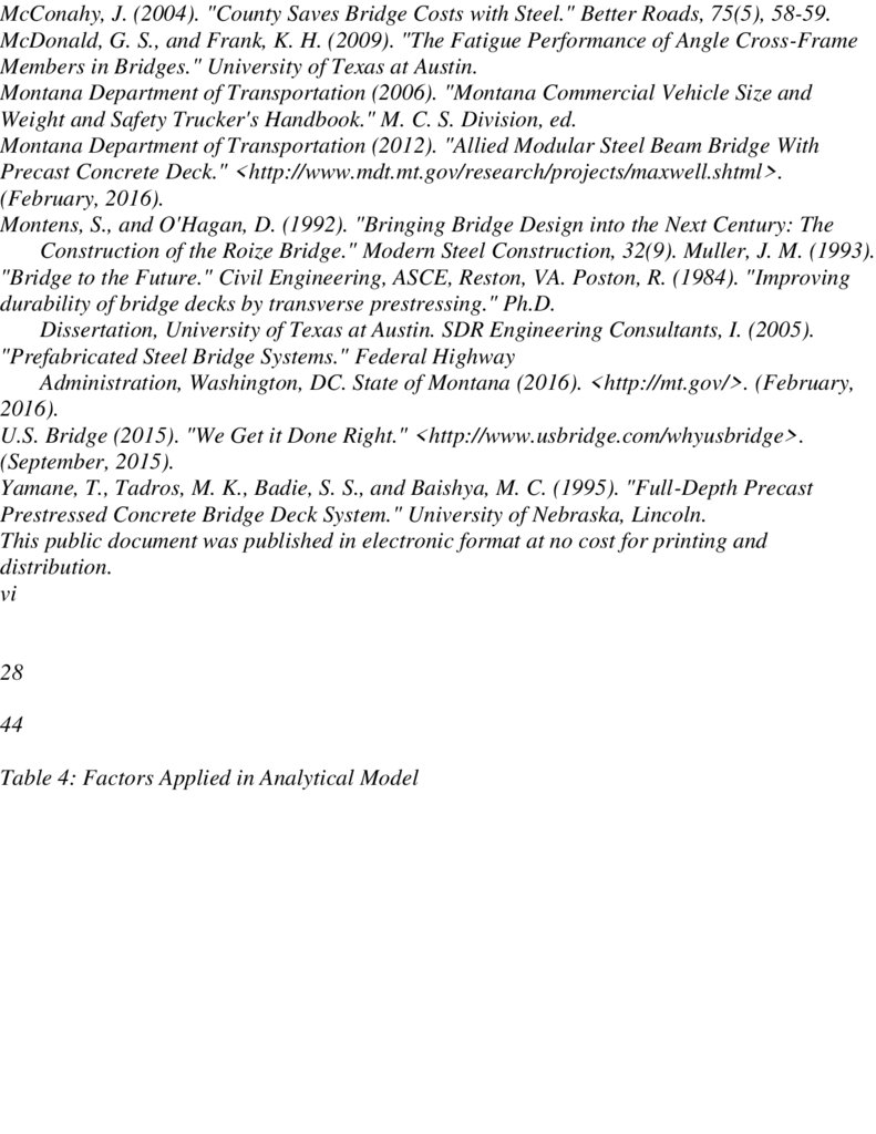
Временные мосты необходимы для обеспечения движения при возведении или
ремонте (реконструкции) капитальных мостовых сооружений, оперативной связи
прерванных путей в различных аварийных ситуациях, для разовых или сезонных
транспортных сообщений.
В мостах такого назначения целесообразны мобильные быстровозводимые
конструкции многократного применения. Инвентарные комплекты сборноразборных мостов разрабатывались и производились прежде всего в интересах
военного ведомства, но в настоящее время широко востребованы и применяются в
гражданском секторе мостостроения в силу их экономичности, мобильности,
доступности в транспортировке. Среди прочих, в том числе и современных
разборных конструкций мостов, особое место занимает средний автомобильный
разборный мост (САРМ), разработанный в 1968 г. и модернизированный в 1982 г. для
нужд Минобороны СССР. В процессе вывода накопленных на хранении комплектов
САРМ в гражданский сектор строительства выяснилась значительная
востребованность этих конструкций, обусловленная следующими их
преимуществами: полная укомплектованность всеми элементами моста, включая
опоры; возможность перекрытия пролетов 18,6, 25,6, 32,6 м с габаритами ездового
полотна 4,2 м при однопутном и 7,2 м при двухпутном проезде...
Однако, смотрите ссылку антисейсмический сдвиговой
фрикционно-демпфирующий компенсатор, фрикци-болт
с гильзой, для соединений секций разборного моста
https://ppt-online.org/1187144
Более подробно смотри автора статьи ТОМИЛОВ СЕРГЕЙ НИКОЛАЕВИЧ
ВЛИЯНИЕ МОНТАЖНЫХ СОЕДИНЕНИЙ СЕКЦИЙ РАЗБОРНОГО МОСТА НА ЕГО
14.
НАПРЯЖЕННО-ДЕФОРМИРОВАННОЕ СОСТОЯНИЕhttps://elibrary.ru/item.asp?id=43813437
Most Bailey bridge USA kompensator uprugoplastichniy gasitel napryajeniy 390 str
https://ppt-online.org/1235890
Mistroy tex zadanie dogovor proektirovanie sborno-razbornix mostov 500 str
https://ppt-online.org/1237042 https://t-s.today/PDF/25SATS220.pdf
Несмотря на наличие современных разработок *7; 8+, инвентарные комплекты
сборно-разборных мостов в процессе вывода их из мобилизационного резерва широко
востребованы в гражданском секторе мостостроения в силу их экономичности,
мобильности, доступности в транспортировке и многократности применения *9;
10].
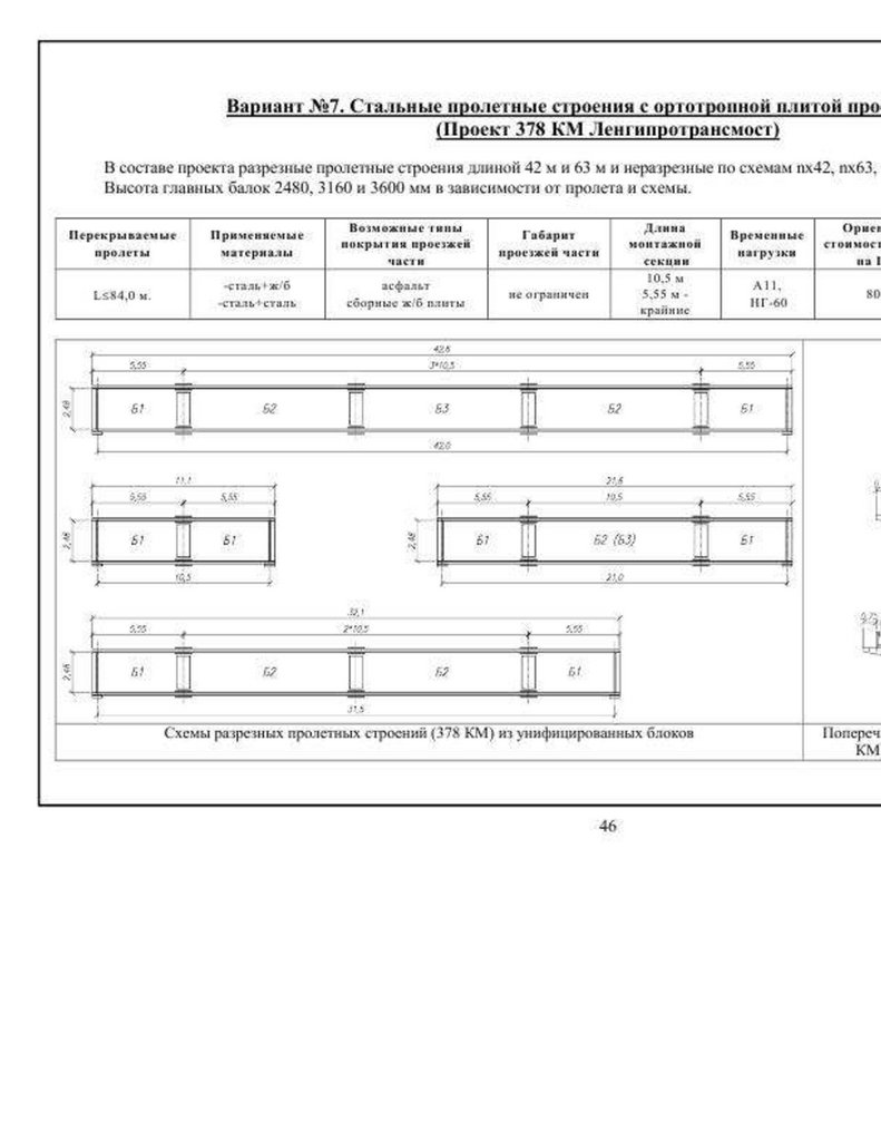
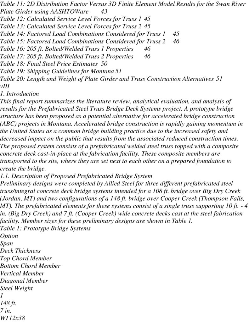
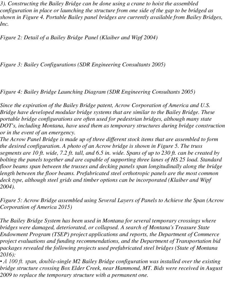
Среди описанных в таблице 1 инвентарных комплектов мостов особое место
занимает САРМ (средний автомобильный разборный мост) 4 . Разработанный в 1968
г. и модернизированный в 1982 г. инвентарный комплект позволяет перекрывать
пролеты 18,6, 25,6 и 32,6 м с габаритом ездового полотна 4,2 м при однопутном и 7,2
м при двухпутном проезде (рисунок 1). Удобный и эффективный в применении
комплект САРМ в процессе вывода накопленных на хранении конструкций в
гражданский сектор строительства показал значительную востребованность,
обусловленную, кроме отмеченных выше преимуществ также и полную
укомплектованность всеми элементами моста, включая опоры. Факт широкого
применения конструкций САРМ в гражданском мостостроении отмечен тем, что
федеральное дорожное агентство «Росавтодор» в 2013 году выпустило
нормативный документ ОДМ 218.2.029 - 20135, специально разработанный для
применения этого инвентарного комплекта.
К недостаткам проекта САРМ следует отнести несоответствия некоторых его
геометрических и конструктивных параметров действующим нормам
проектирования: габариты ездового полотна 4,2 м при однопутном и 7,2 м при
двухпутном проезде, также штатные инвентарные ограждения (колесоотбои) не
соответствуют требованиям действующих норм СП 35.1333.20116, ГОСТ Р 5260720067, ГОСТ 26804-20128. Выполнение требований указанных выше норм может быть
обеспечено ограничением двухсекционной поперечной компоновки однопутным
15.
проездом с установкой добавочных ограждений *10+ или нештатной поперечнойкомпоновкой в виде трех и более секций, рекомендуемой нормами ОДМ 218.2.029
20135.
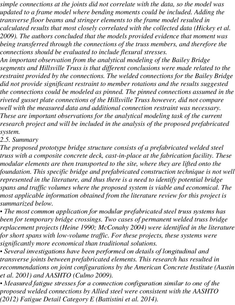
Пролетное строение среднего автомобильного разборного моста (САРМ) в
продольном направлении набирается из средних и концевых секций расчетной длиной
7,0 и 5,8 м соответственно. Количество средних секций (1, 2 или 3) определяет
требуемую в каждом конкретном случае длину пролета 18,6, 25,6, 32,6 м (рисунок 1).
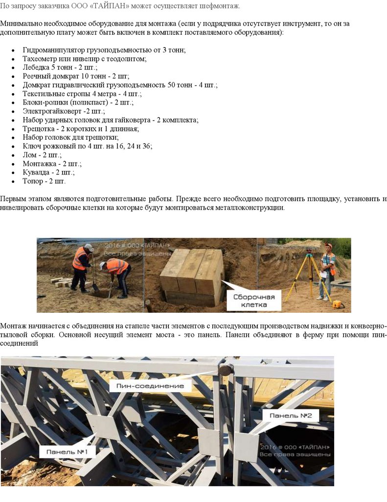
Объединение секций в продольном направлении в сечениях 3 (рисунок 1)
выполняется с помощью штырей, вставляемых в отверстия (проушины) верхнего и
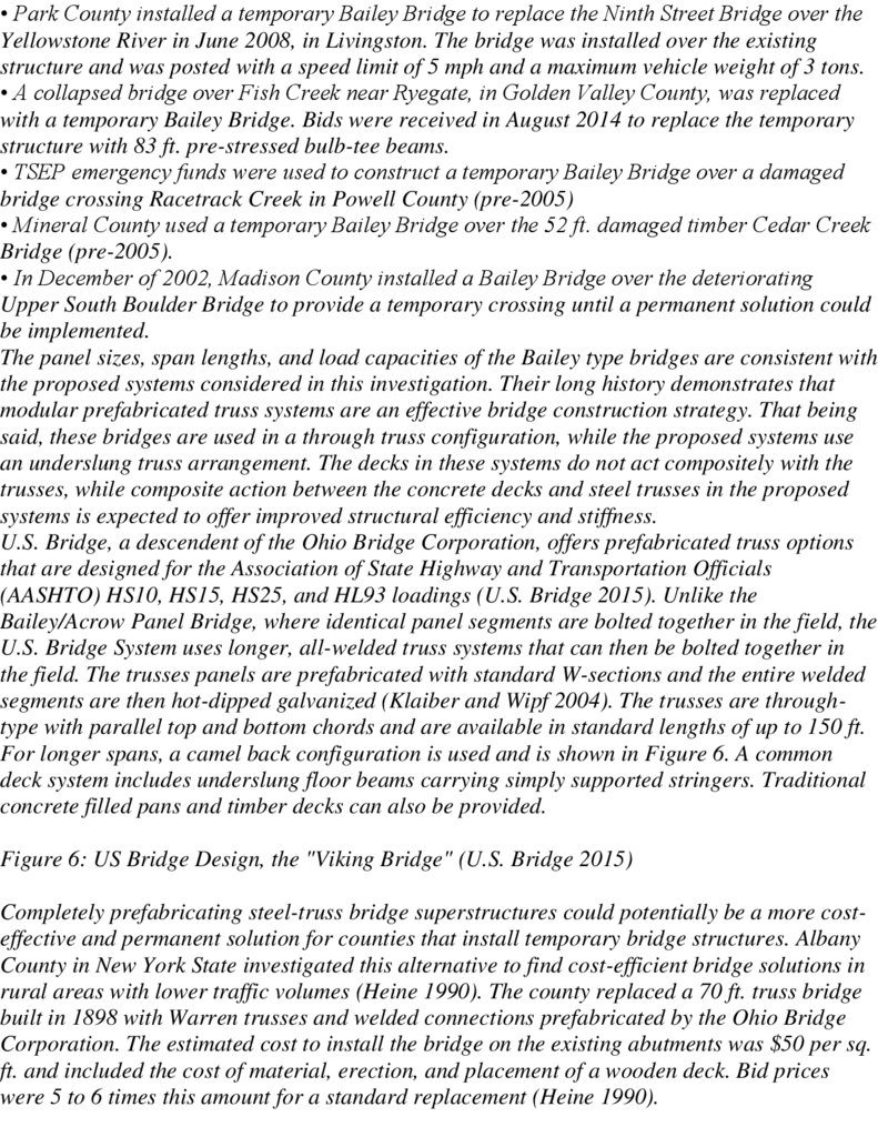
нижнего поясов секций. В поперечном направлении в стыке одной секции расположены
два штыревых соединения в уровне верхнего и два - в уровне нижнего пояса (рисунок
2).
4 Средний автодорожный разборный мост. Техническое описание и инструкция по
эксплуатации / Министерство обороны СССР. -М.: Военное изд-во мин. обороны СССР,
1982. - 137 с.
5 Методические рекомендации по использованию комплекта среднего
автодорожного разборного моста (САРМ) на автомобильных дорогах в ходе
капитального ремонта и реконструкции капитальных искусственных сооружений:
Отраслевой дорожный методический документ ОДМ 218.2.029 - 2013. - М.:
Федеральное дорожное агентство (РОСАВТОДОР), 2013. - 57 с.
6 Свод правил. СП 35.13330.2011. Мосты и трубы. Актуализированная редакция
СНиП 2.05.03-84* (с Изменениями № 1, 2) / ОАО ЦНИИС. - М.: Стандартинформ, 2019.
7 ГОСТ Р 52607-2006. Технические средства организации дорожного движения.
Ограждения дорожные удерживающие боковые для автомобилей. Общие
технические требования / ФДА Минтранса РФ, ФГУП РосдорНИИ, Российский
технический центр безопасности дорожного движения, ОАО СоюздорНИИ, МАДИ
(ГТУ), ДО БДД МВД России, НИЦ БДДМВД России. - М.: Стандартинформ, 2007, - 21 с.
8 ГОСТ 26804-2012. Ограждения дорожные металлические барьерного типа.
Технические условия / ЗАО СоюздорНИИ, ФГУП РосдорНИИ, ООО НПП «СК Мост». - М.:
Стандартинформ, 2014, - 24 с.
16.
Страница 4 из 1425SATS220
1 - концевая секция; 2 - средняя секция; 3 - сечения штыревых соединений секций
Рисунок : Томилова Сергей Николаевича вставлен
Рисунок 1. Фасад пролетного строения разборного моста САРМ с вариантами длины
18,6 м (а), 25,6 м (б), 32,6 м (в) (разработано автором)
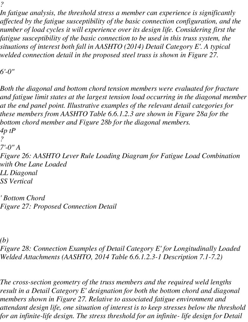
Каждое соединение верхнего пояса секций включает тягу в виде пластины с двумя
отверстиями и два вертикальных штыря, а соединение нижнего пояса выполнено
одним горизонтальным штырем через проушины смежных секций (рисунок 4).
Таким образом, продольная сборка пролетного строения осуществляется путем
выгрузки и проектного расположения секций, совмещения проушин смежных секций и
постановки штырей.
17.
1 - штыревые соединения верхнего пояса; 2 - штыревые соединения нижнего пояса; а расстояние между осями штыревых соединенийРисунок 2. Двухсекционная компоновка поперечного сечения пролетного строения
(разработано автором)
Постановка задачи
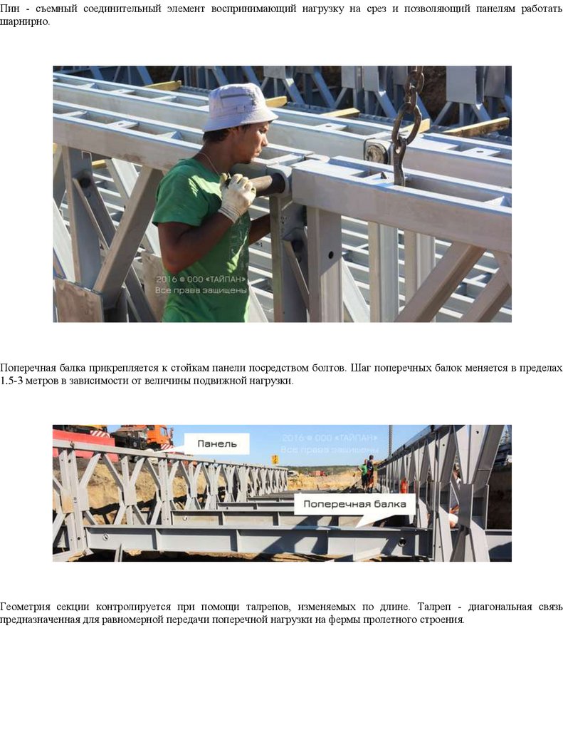
Штыревое соединение секций пролетных строений позволяет значительно
сократить время выполнения работ, но это обстоятельство оборачивается и
недостатком - невозможностью обеспечения плотного соединения при работе его
на сдвиг. Номинальный диаметр соединительных штырей составляет 79 мм, а
отверстий под них и проушин - 80 мм.
Разница в 1 мм необходима для возможности постановки штырей при сборке
пролетных строений.
Цель настоящего исследования - оценить напряженное состояние узла штыревого
соединения, сравнить возникающие в материале элементов соединения напряжения
18.
смятия и среза с прочностными параметрами стали, возможность проявленияпластических деформаций штыря и проушин и как следствие - их влияние на общие
деформации пролетного строения.
Штыревые соединения как концентраторы напряжений в конструкциях мостов
уже привлекали внимание исследователей *11+ и также отмечался характерный для
транспортных сооружений фактор длительного циклического воздействия *8+.
Изначально неплотное соединение «штырь-проушина» и дальнейшая его выработка
создает концентрацию напряжения до 20 % против равномерного распределения
*11+, что может привести к ускорению износа, особенно с учетом цикличного и
динамического воздействия подвижной автотранспортной нагрузки.
В настоящей статье рассмотрены напряжения смятия и деформации в
штыревых соединениях и как их следствие - общие деформации (прогибы) пролетного
строения. Оценка напряженного состояния в соединении выполнена исходя из
гипотезы равномерного распределения усилий по расчетным сечениям.
Сравнительный расчет выполним для распространенного пролета 32,6 м в
следующей последовательности: прочность основного сечения одной секции при
изгибе; прочность штыревого соединения по смятию металла проушин; прочность
металла штыря на срез.
Паспортная (проектная) грузоподъемность при двухсекционной поперечной
компоновке и двухпутном ездовом полотне - временные вертикальные нагрузки Н-13,
НГ-60 по нормам СН 200-621. Так как конструкции САРМ запроектированы на нагрузки,
уступающие современным, то для обеспечения приемлемой грузоподъемности
можно использовать резервы в компоновке - например двухсекционная поперечная
компоновка будет пропускать только одну полосу движения, что на практике
зачастую не организовано и транспорт движется двумя встречными полосами.
Рассмотрим именно такой случай и в качестве полосной автомобильной нагрузки
примем А11 по СП 35.1333.20116, хотя и меньшую, чем принятая для нового
проектирования А14, но в полной мере отражающую состав транспортных средств
регулярного поточного движения. При постоянстве поперечного сечения по длине
пролета и исходя из опыта проектирования для оценочного усилия выбираем
изгибающий момент.
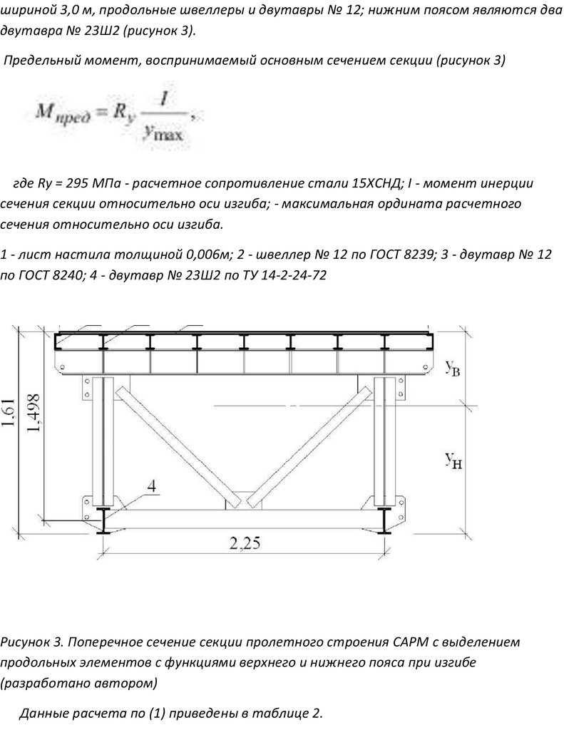
В работе основного сечения одной секции при изгибе участвуют продольные
элементы верхнего и нижнего пояса: верхним поясом являются лист настила
19.
шириной 3,0 м, продольные швеллеры и двутавры № 12; нижним поясом являются двадвутавра № 23Ш2 (рисунок 3).
Предельный момент, воспринимаемый основным сечением секции (рисунок 3)
где Ry = 295 МПа - расчетное сопротивление стали 15ХСНД; I - момент инерции
сечения секции относительно оси изгиба; - максимальная ордината расчетного
сечения относительно оси изгиба.
1 - лист настила толщиной 0,006м; 2 - швеллер № 12 по ГОСТ 8239; 3 - двутавр № 12
по ГОСТ 8240; 4 - двутавр № 23Ш2 по ТУ 14-2-24-72
Рисунок 3. Поперечное сечение секции пролетного строения САРМ с выделением
продольных элементов с функциями верхнего и нижнего пояса при изгибе
(разработано автором)
Данные расчета по (1) приведены в таблице 2.
20.
Расчет предельного изгибающего момента основного сечения секции САРМРасчет предельного изгибающего момента основного сечения секции САРМ
Для сравнительной оценки несущей способности основного сечения секции
(предельный изгибающий момент, таблица 2) представим расчетный изгибающий
момент от временной нагрузки А11 для двухпутного проезда, а именно 1 полоса А11 на 1 секцию в поперечном направлении.
Для выделения полезной части грузоподъемности из предельного удерживается
изгибающий момент от постоянной нагрузки. Расчетными сечениями по длине
пролета принимаем его середину и сечение штыревого соединения, ближайшее к
середине пролета. Результаты расчета путем загружения линий влияния
изгибающего момента в выбранных сечениях приведены в таблице 3.
Как видно, предельный изгибающий момент основного сечения секции (3894,9 кН-м)
только на 59,4 % обеспечивает восприятие момента (1134,5 + 5418,6 = 6553,1 кН-м)
от суммы постоянной и временной А11 расчетных нагрузок.
Оценить напряженное состояние металла проушин по смятию штырем можно по
схеме контакта штыря с внутренней поверхностью проушин, где усилие N с плечом a
составляет внутренний момент, уравновешивающий внешний, обусловленный
нагрузкой на пролет (рисунок 4).
21.
Рисунок 5. Схема штыревого соединения нижнего пояса, вид сверху (разработаноавтором). Но , есть упругопластический сдвиговой компенсатор гаситель сдвиговых
напряжений для быстро собираемых на антисейсмических фрикционно-подвижных соединениях
для сборно–разбороного железнодорожного армейского моста и он надежнее
1 - одинарная проушина; 2 - двойная проушина; 3 - штырь
Сравним полученные в (3) и (4) результаты с прочностными характеристиками
стали 15ХСНД, из которой изготовлены несущие элементы моста САРМ, таблица 4.
Следует определить суммарный расчетный изгибающий момент М от
постоянной Мпост и временной Мвр (А11) нагрузок для сечения ближайшего к
середине пролета стыка по данным таблицы 3.
M = Mпост + Mвр = 1081,2 + 5195,3 = 6276,5 кН- м.
1 - вертикальный штырь верхнего пояса; 2 - горизонтальный штырь нижнего пояса
Рисунок 4. Схема стыка секций пролетного строения
При суммарной толщине элементов проушины нижнего пояса, сминаемых в одном
направлении, 0,06 м и диаметре штыря 0,079 м площадь смятия составит А = 0,060,079 = 0,0047 м2 на один контакт (рисунок 5). При наличии двух контактов нижнего
пояса в секции напряжение смятия металла проушины составит
22.
Для расчета сечения штыря на срез следует учесть, что каждый из двух контактовна секцию имеет две плоскости среза (рисунок 5), тогда напряжение сдвига
Примечание:расчетные сопротивления стали смятию и сдвигу определены по
таблице 8.3 СП 35.13330.20116 (составлено автором)
Сравнение полученных от воздействия нагрузки А11 напряжений с
характеристиками прочности стали 15ХСНД
Напряжение сдвига в штыре превосходит расчетное сопротивление стали, а
напряжение смятия в контакте штырь-проушина превосходит как расчетное
сопротивление, так и предел текучести, что означает невыполнение условия
прочности, выход металла за предел упругости и накопление пластических
деформаций при регулярном и неорганизованном воздействии временной нагрузки
А11.
Практическое наблюдение
В организациях, применяющих многократно использованные конструкции САРМ,
отмечают значительные провисы (прогибы в незагруженном состоянии) пролетных
строений, величина которых для длин 32,6 м доходит до 0,10-0,15 м. Это создает
искажение продольного профиля ездового полотна и негативно влияет на
пропускную способность и безопасность движения. При этом визуально по линии
прогиба отчетливо наблюдаются переломы в узлах штыревых соединений секций.
При освидетельствовании таких пролетных строений отмечается повышенный
зазор между штырем и отверстием (рисунок 6).
23.
Рисунок 6. Повышенный зазор в штыревом соединении секций пролетного строенияСАРМ (разработано автором)
Смещения в штыревых соединениях, обусловленные пластическими деформациями
перенапряженного металла, определяют величину общих деформаций (прогибов)
пролетных строений (рисунок 7).
24.
Рисунок 7. Схема общих деформаций вследствие смещения в штыревых соединениях(разработано автором)
Полное смещение (подвижка) на одно соединение с0 = с + с2, где с1 = 1 мм - исходное
конструктивное; с2 - добавленное за счет смятия в соединении (рисунок 7).
Вертикальное перемещение f (прогиб) в середине пролета для рассмотренного
примера будет суммой xi и Х2 (рисунок 7).
f = Xi + Х2.
Величины x1 и x2 можно определить, зная углы а и 2а, которые вычисляются через
угол
где а - расстояние между осями штыревых соединений верхнего и нижнего поясов;
I1 - длина средней секции пролетного строения; I2 - длина концевой секции
пролетного строения.
В качестве примера рассмотрим временный объездной мост через р. Черниговка
на автодороге Хабаровск - Владивосток «Уссури», который был собран и
эксплуатировался в составе одного пролета длиной 32,6 м из комплекта САРМ на
период строительства постоянного моста. Были отмечены значительные провисы
пролетных строений временного моста величиной в пределах 130-150 мм в середине
пролета, что вызвало беспокойство организаторов строительства. При
обследовании была установлена выработка всех штыревых соединений главных
ферм в среднем на 2,5 мм сверх номинального 1 мм.
25.
Таким образом смещение (подвижка) на одно соединение с0 = с1 + с2 = 1 + 2,5 = 3,5мм, а так как в уровне верхнего пояса в качестве связующего элемента применена
продольная тяга с двумя отверстиями и двумя расположенными последовательно
штырями, то суммарное смещение, отнесенное к уровню нижнего пояса с = 3,5-3 =
10,5 мм.
Далее следуют вычисления по формулам (5) при а = 1,37 м; h = 7,0 м; I2 = 5,8 м.
а = arcsin 0,0105 = 0,205o; а = 2 • 0,205 = 0,41o; xi = 7,0 • sin 0,41 = 0,05 м;
2 2 • 1,47
1
2а = 2 • 0,41 = 0,82o; x2 = 5,8 • sin 0,82o = 0,083 м.
Полная величина прогиба f = Х1 + Х2 = 0,05 + 0,083 = 0,133 м, что вполне согласуется
с фактически замеренными величинами f.
Заключение по использованию упругопластического сдвигового
компенсатора гасителя сдвиговых напряжений для быстро
собираемых на антисейсмических фрикционно-подвижных
соединениях для сборно–разборного железнодорожного
армейского моста
1. Штыревые монтажные соединения секций разборного
пролетного строения временного моста позволяют существенно
ускорить процесс возведения и последующей разборки
конструкций, однако при этом являются причиной увеличения
общих деформаций пролетного строения, кроме
упругопластического сдвигового компенсатора, гасителя
сдвиговых напряжений для быстрособираемых на
антисейсмических фрикционно-подвижных соединениях для
сборно–разборного железнодорожного армейского моста проф
дтн ПГУПС А.М.Уздина
26.
2. Штатное двухпутное движение при двухсекционнойкомпоновке конструкций САРМ под современной автомобильной
нагрузкой не обеспечено прочностью как основного сечения секций,
так и элементов штыревых соединений, а использование
упругопластического сдвигового , компенсатора, гасителя
сдвиговых напряжений для быстро собираемых на
антисейсмических фрикционно-подвижных соединениях для
сборно–разборного железнодорожного армейского моста , все
напряжения снимает
3. В металле элементов штыревых соединений при
современной нагрузке накапливаются пластические деформации,
приводящие к выработке контактов «штырь-проушина» и
нарастанию общих деформаций (провисов), а упругопластический
сдвиговой компенсатор гаситель сдвиговых напряжений для
быстрособираемых на антисейсмических фрикционно-подвижных
соединениях для сборно–разборного железнодорожного
армейского моста гасить напряжения
4. Ускорению процесса износа элементов штыревых соединений
способствует многократная сборка-разборка пролетных
строений и их эксплуатация под интенсивной динамической
нагрузкой и не гасит сдвиговых напряжений для быстро
собираемых на антисейсмических фрикционно-подвижных
соединениях для сборно–разборного железнодорожного
армейского моста
5. Образующийся провис пролетного строения создает
ненормативное состояние продольного профиля ездового
полотна, снижающее пропускную способность и безопасность
27.
движения, упругопластический сдвиговой компенсатор гасительсдвиговых напряжений для быстро собираемых на
антисейсмических фрикционно-подвижных соединениях для
сборно–разборного железнодорожного армейского моста
сдвиговый нагрузки «поглощает»
6. Изначально разборные конструкции САРМ проектировались
под нужды военного ведомства для мобильного и
кратковременного применения и штыревые монтажные
соединения в полной мере соответствуют такому назначению.
При применении в гражданском строительстве эту особенность
следует учитывать в разработке проектных решений,
назначении и соблюдении режима эксплуатации, например путем
уменьшения полос движения или увеличения числа секций в
поперечной компоновке, а использование сдвигового
компенсатора, гасителя сдвиговых напряжений для быстро
собираемых на антисейсмических фрикционно-подвижных
соединениях для сборно–разборного железнодорожного
армейского моста исключает обрушение железнодорожного
моста
Дальнейшие исследования видятся в аналитическом обзоре
применяемых конструкций разборных мостов, разработке
отвечающих современным требованиям проектных решений
вариантов поперечной и продольной компоновки пролетных
строений с использованием упругопластических , сдвиговых
компенсатор, которые гасят, сдвиговые напряжения для
быстро собираемых, на антисейсмических фрикционно-
28.
подвижных соединениях , для отечественного сборно–разборногожелезнодорожного армейского моста «Уздина»
ЛИТЕРАТУРА
1. Кручинкин А.В. Сборно-разборные временные мосты. - М.: Транспорт, 1987. - 191 с.
2. Тыдень В.П., Малахов Д.Ю., Постников А.И. Реализация современных требований к
переправочно-мостовым средствам в концепции выгружаемого переправочнодесантного парома // Вестник Московского автомобильно- дорожного
государственного технического университета (МАДИ). - М.: Изд-во МАДИ(ГТУ), 2019.
- Вып. 3 (58). - С. 69-74.
3. Томилов С.Н. О применении стальных пакетных конструкций в постоянных мостах
// Научные чтения памяти профессора М.П. Даниловского: материалы
Восемнадцатой Национальной научно-практической конференции: в 2 т. - Хабаровск:
Изд-во Тихоокеан. гос. ун-та, 2018. - 2 т. - С. 360-363.
4. Mohamad Nabil Aklif Biro, Noor Zafirah Abu Bakar. Design and Analysis of Collapsible
Scissor Bridge. MATEC Web of Conferences. Vol. 152, 02013 (2018). DOI:
https://doi.org/10.1051/matecconf/201815202013.
5. Дианов Н.П., Милородов Ю.С. Табельные автодорожные разборные мосты: учебное
пособие. - М.: Изд-во МАДИ (ГТУ), 2009. - 236 с.
6. Adil Kadyrov, Aleksandr Ganyukov, Kyrmyzy Balabekova. Development of Constructions of
Mobile Road Overpasses. MATEC Web of Conferences. Vol. 108, 16002 (2017). DOI:
https://doi.org/10.1051/matecconf/201710816002.
7. Бокарев С.А., Проценко Д.В. О предпосылках создания новых конструкций временных
мостовых сооружений // Интернет-журнал «Науковедение». 2014. № 5(24). URL:
https://naukovedenie.ru/PDF/26KO514.pdf. - С. 1-11.
8. Проценко Д.В. Совершенствование конструктивно-технологических параметров
системы несущих элементов и элементов проезжей части универсального сборноразборного пролетного строения с быстросъемными шарнирными соединениями.
Диссертация на соискание ученой степени кандидата технических наук / Сибирский
государственный университет путей сообщения (СГУПС). Новосибирск: 2018.
29.
9. Матвеев А.В., Петров И.В., Квитко А.В. Оценка по теории инженерногопрогнозирования новых образцов мостового имущества МЛЖ-ВФ-ВТ и ИМЖ- 500 //
Вестник гражданских инженеров. - СПб: Изд-во Санкт-Петербургского гос. арх.строит. ун-та, 2018. Вып. 4 (69). - С. 138-142.
10. Томилов С.Н., Николаев А.Р. Применение комплекта разборного моста под
современные нагрузки // Дальний Восток. Автомобильные дороги и безопасность
движения: международный сборник научных трудов (под. ред. А.И. Ярмолинского). Хабаровск: Изд-во Тихоокеан. гос. ун-та, 2018. - № 18. - С. 125-128.
11. Сухов И.С. Совершенствование конструктивно-технологических решений
шарнирных соединений автодорожных мостов. Автореферат диссертации на
соискание ученой степени кандидата технических наук / Научно- исследовательский
институт транспортного строительства (ОАО ЦНИИС). М.: 2011.
30.
31.
32.
33.
34.
35.
36.
37.
38.
39.
40.
41.
42.
43.
44.
45.
46.
47.
48.
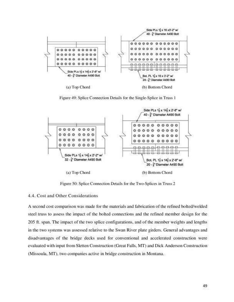
49.
50.
51.
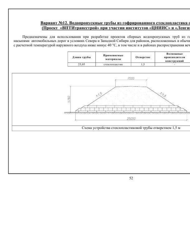
52.
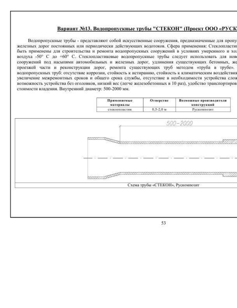
53.
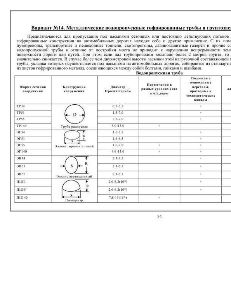
54.
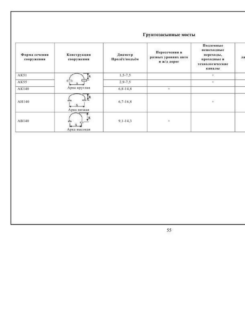
55.
56.
57.
58.
59.
60.
61.
62.
63.
64.
65.
66.
67.
68.
Конструктивные системы в природе и строительной техникеТемнов В. Г. 1987 г. https://dwg.ru/lib/1147
В книге освещены вопросы организации конструктивных систем организмов живой природы в процессе эволюции. Рассмотрены
бионические принципы оптимизации конструктивных систем. Впервые предложены алгоритмы синтеза оптимальных конструктивных
систем на основе бионических принципов. Представлены строительные конструкции, созданные на основе бионических принципов, и
освещен опыт их применения в практике строительства.
Книга предназначена для научных и инженерно-технических работников.
ПРИНЯТИЕ РЕШЕНИЙ ПРИ ПРОЕКТИРОВАНИИ
ИСКУССТВЕННОЙ СРЕДЫ ОБИТАНИЯ С ИСПОЛЬЗОВАНИЕМ
69.
БИОНИЧЕСКИХ ПРИНЦИПОВ КОНСТРУИРОВАНИЯ1
ТЕМНОВ ВЛАДИМИР ГРИГОРЬЕВИЧ 1
Петербургский государственный университет путей сообщения
https://www.elibrary.ru/item.asp?id=17303643
https://cyberleninka.ru/article/n/ekologiya-i-arhitekturnaya-tektonika-stroitelnyh-obektov-gorodskoy-sredy-obitaniya
Книга Темновва В Г СПб ГАСУ зам президента "Сейсмофонд" при СПб ГАСУ ОГРН:
Темнов В Г дтн, проф ПГУПС аттестата испытательной лаборатории СПб ГАСУ № RA.RU.21СТ39 от 27.05.2015 (999) 535-47-29
Темнов В Н Подтверждение компетентности Номер решения о прохождении процедуры подтверждения компетентности
8590-гу (А-5824) Сведения об аккредитации проф СПб ГАСУ В. Г.Темнова
https://pub.fsa.gov.ru/ral/view/26088/applicant
Егорова Ольга Александровна Преподаватель ПГГУПС Теоретическая механика (МТ
Президент ОО «СейсмоФонд» Х.Н.Мажиев , ИНН 2014000780 [email protected] (994) 434-44-70
СПб ГАСУ проф. дтн Ю.Л.Рутман СПб ГАСУ автор статьи "Пластичность при сейсмическом проектировании зданий и
сооружений" для гашения динамических колебаний [email protected] тел (911) 175-84-65
СПб ГАСУ доц. ктн И.У.Аубакирова [email protected] (996) 798-26-54 , (812) 694-78-10
СПб
ГАСУ проф дтн Ю М Тихонов [email protected] [email protected] ( 951) 644-16-48
Редакция газеты Земля РОССИИ и Крестьянское информационное агентство ждет помощи от депутата ГД РФ от КПРФ
Виктор Ивановича Соболева для боевых братьев, ветеранов боевых действий сражающихся за Русский мир в Киевской Руси,
где приходится преодолевать водные преграды 11 мая 2022г, при отсутствии армейских быстрособираемых сборноразборных универсальных мостов -переправ (гаубиц М 777 уничтожила российские понтонные мосты ) , где под Белогоровкой, через
реку Северский Донец, из 550 военнослужащих из семьдесят четвёртой мотострелковой бригады выжило только 65 русских
военнослужащих . (11 мая украинская артиллерия с гаубиц М 777 уничтожила российские понтонные мосты и плотно сконцентрированные
вокруг них российские войска и технику, в результате чего, погибло 485 человек и было повреждено более 80 единиц техники )
Газета ЗЕМЛЯ РОССИИ Доброго времени суток Ваше сообщение получено, информация будет изучена и применена в
дальнейшей работе в случае её актуальности. С Уважением, В.И. Соболев [email protected]
70.
Газета ЗЕМЛЯ РОССИИ <[email protected]> писал(а): Антисейсмические устройства в мостостроении 1972 или конструктор длявзрослых Преодоление водных препятствий всегда было существенной проблемой для армии. Все изменилось в начале 1940-х
годов благодаря британскому
инженеру-строителю Дональду Бэйли, который спроектировал необычный балочный
мост, названный в честь его имени "Bailey bridge". https://ppt-online.org/1159614 https://disk.yandex.ru/d/Tk25oTCT-3aaLA
https://zen.yandex.ru/media/guns_review/most-beili-chudo-britanskoi-injenerii-vtoroi-mirovoi-voiny-5d3cbda2027a1500beff7356
https://www.9111.ru/questions/7777777771895950/
https://vk.com/sertifikatsiya45
https://pdsnpsr.ru/articles/11731-kogda-savl-stanet-pavlom_10032022
https://ppt-online.org/1156971
https://vk.com/wall441435402_1665 https://ok.ru/profile/597112530458/statuses/154744951770394
https://diary.ru/~krestyaninformburo/p221185666_preodolenie-vodnyh-prepyatstvij-vsegda-bylo-suwestvennoj-problemoj-dlya-armiido-vtoro.htm http://ooc.su/gb
https://stroyone.com/bridge/bailey-bridge.html
https://bukvoed.livejournal.com/338402.html
https://docs.cntd.ru/document/1200075951
https://ppt-online.org/848180
Обеспечение сейсмической надежности антисейсмических демпфирующих косых компенсаторов с перемещениями на
фрикционно – подвижных болтовых соединениях, для обеспечения
сейсмостойкости технологических трубопроводов из полиэтилена, для установки
очистки хозяйственно –бытовых сточных вод КОС «Гермес Групп», для увеличения
демпфирующей способности косого компенсатора , преимущественно при
импульсных растягивающих нагрузках , согласно изобретениям проф. дтн ПГУПС
А.М.Уздина №№ 1143895, 1168755, 1174616, 165076 "Опора сейсмостойкая",
2010136746 "Способ защита зданий и сооружений при взрыве с использованием
сдвигоустойситвых и легко сбрасываемых соединений , использующие систему
демпфирования фрикционности и сейсмоизоляцию для поглощения взрывной и
сейсмической энергии" https://programmersought.com/article/38523555097/
https://yadi.sk/i/z6_3wOS_SobMCQ https://yadi.sk/i/oGs8NElm7_szCg
https://ppt-online.org/863358 https://ok.ru/video/2020159654625
https://www.iitk.ac.in/nicee/wcee/article/13_966.pdf
https://programmersought.com/article/38523555097/
https://interestingengineering.com/a-cautionary-tale-the-tacoma-narrows-bridge-collapse
https://ok.ru/video/3939035318998 https://ok.ru/video/myVideo
https://disk.yandex.ru/i/cUpjadHPtTW1dw<неиhttps://ppt-online.org/1159781
https://ppt-online.org/1159782 https://ppt-online.org/1159783
PGUPS antiseismocheskoe flantsevoe friktsionnoe soedinenie dlya sborno-razbornogo
mosta 439 str Соболев В.И. *[email protected]+
71.
Для Соболева Виктор Ивановичу КПРФ ОБЩЕРОССИЙСКОЕ ОБЩЕСТВЕННОЕ ДВИЖЕНИЕ «В ПОДДЕРЖКУ АРМИИ,ОБОРОННОЙ ПРОМЫШЛЕННОСТИ И ВОЕННОЙ НАУКИ» 127051, г. Москва, ул. Трубная, д. 19/12 стр.2 Тел. +7(905) 782-82-66
[email protected],ru
Прилагается изобретение проф дтн ПГУПС Уздина А М например : Скоростной способ восстановление конструкций участка автодорожного
моста неразрезной системы из типовых пространственных перекрестного-стержневых комбинированных конструкций, из замкнутым
гнутосварных прямоугольных профилей серии 1.460.3 -14 "Молодечно", МАРХИ ПСПК, "Кисловодск" пролетами 18, 24 и 30 метров,
разработанные и изобретенные в СССР, но внедрены (патентное ворье смотри ссылку : https://politikus.ru/v-rossii/85673-patentovannoe-voreamerikancy-kradut-u-nas-ne-tolko-izobreteniya-no-dazhe-pesni.html https://politikus.ru/v-rossii/85673-patentovannoe-vore-amerikancy-kradut-unas-ne-tolko-izobreteniya-no-dazhe-pesni.html ) нашими партнерами из блока НАТО, при восстановлении разрушенных мостов в
Афганистане, Ираке Смотри: Logistic Support Bridge
Преодоление водных препятствий всегда было существенной проблемой для армии. Все изменилось в начале 1983 году благодаря проф
дтн ЛИИЖТ А.М.Уздину , который получил патент № 1143895, 1168755, 1174616, 2550777 на сдвиговых болтовых соединениях, а
инженер -механик Андреев Борис Иванович получил патент № 165076 "Опора сейсмостойкая" и № 2010136746 "Способ защита здания и
сооружений " который спроектировал необычный сборно-разборный универсальный железнодорожный мост" с использование
антисейсмических фланцевых соединений для сборно-разборного моста" , названный в честь его имени в честь русского ученого,
изобретателя "Мост Уздина". Но мост Уздина , пока на бумаге.
Зато, западные партнеры из блока НАТО , уже внедрили изобретения проф дтн ПГУПС Уздина А М. по использованию сдвигового
компенсатора под названием Bailey bridge. https://ppt-online.org/1159614 https://disk.yandex.ru/d/Tk25oTCT-3aaLA
ЮРИЙ ПОДОЛЯКА ПОД БЕЛОГОРОВКОЙ о ситуации, произошедшей на переправе у Белогоровки, где из-за крайне неудачной организации
переправы под артиллерийские удары ВСУ попала целая батальонно-тактическая группа. https://vk.com/wall-86201393_66116
Под Белогоровкой: Что произошло на переправе через реку Северский Донец Подробнее: https://eadaily.com/ru/news/2022/05/15/razgrompod-belogorovkoy-chto-proizoshlo-na-pereprave-cherez-reku-severskiy-donec На переправе Северский Донец из 550 ветеранов боевых действий
выжило только 65. В Луганской области при форсировании реки Северский Донец российская армия потеряла 485 военнослужащих
семьдесят четвёртой мотострелковой бригады. Об этом сообщил американский Институт изучения войны. «11 мая украинская артиллерия с
гаубиц М 777 уничтожила российские понтонные мосты и плотно сконцентрированные вокруг них российские войска и технику, в результате
чего, как сообщается, погибло 485 человек и было повреждено более 80 единиц техники», — отмечается в публикации. По оценке института,
войска РФ допустили значительные тактические ошибки при попытке форсирования реки в районе Кременной, что привело к таким потерям.
Ранее в Институте изучения войны отмечали, что российские войска сосредотачиваются на битве за Северодонецк, отказавшись от плана
крупномасштабного окружения ВСУ и выхода на административные границы Донецкой области.
https://www.youtube.com/watch?v=CNI4fcgJ26Y https://eadaily.com/ru/news/2022/05/15/razgrom-pod-belogorovkoy-chto-proizoshlo-napereprave-cherez-reku-severskiy-donec https://ok.ru/profile/580659891158/statuses/154786195665878 Более подробно быстрособираемых
универсальных сборно-разборных мостов Уздина модернизированных, улучшенных для переврав в Киевской Руси для форсирования
мотострелковых бригад через реку Северный Донец смотрите аналог моста Дональда Бейли по ссылкам : Bailey Bridge bay detail
https://www.fhwa.dot.gov/bridge/prefab/psbsreport03.cfm
Инструкция по возведению моста Уздина на английском языке Nycnherwbz Bailey Bridge-revised https://ppt-online.org/1159973
Чертежи на английском языке сборно-разборного быстрособираемого моста Уздина для уменьшения потерь русской армии PNABS580
https://ppt-online.org/1159974
Инструкция на английском языке Newhouse https://ppt-online.org/1159974
Построенные в Великобритании сборно -разборный мосты Уздина без фланцевых фрикционных сдвиговых компенсаторов имеют
локальные разрушения Newhouse https://ppt-online.org/1159981
Разрушенные сборно-разборные мосты смонтированные без сдвигового компенсатора проф Уздина А М см изобретение Андреева Борис
Александровича и др № 165076 "Опора сейсмостойкая" , 2010136746
posts-67-structural-assessment-of-collapsed-bailey-bridge-over-tuirini-river1 (1) https://ppt-online.org/1159982
Мост Бейли чертежи fm5-277(86) (1) https://ppt-online.org/1155559
Антисейсмические устройства для мостов СССР 1972 https://ppt-online.org/1159782
72.
Bailey Bridge bay detail https://www.fhwa.dot.gov/bridge/prefab/psbsreport03.cfmЧертежи сборно -разборного быстрособираемого моста The Army Technical Manual Tm5-277 Bailey Bridge
https://archive.org/details/in.ernet.dli.2015.164262/..
The Army Technical Manual Tm5-277 Bailey Bridge http://www.bits.de/NRANEU/others/amd-us-archive/fm5-2..
<iframe src="https://archive.org/embed/in.ernet.dli.2015.164262" width="560" height="384" frameborder="0" webkitallowfullscreen="true"
mozallowfullscreen="true" allowfullscreen></iframe>
[archiveorg in.ernet.dli.2015.164262 width=560 height=384 frameborder=0 webkitallowfullscreen=true mozallowfullscreen=true]
http://www.bits.de/NRANEU/others/amd-us-archive/fm5-2..
https://archive.org/details/in.ernet.dli.2015.164262/..https://archive.org/details/DepartmentOfTheArmyTechni..
Prefabricated Steel Bridge Systems Final Report 26 str https://ppt-online.org/1160006 Научная публикация на английском языке об
использовании за рубежом сдвигового компенсатора Уздина для мостов 000805895 https://ppt-online.org/1160008 https://pptonline.org/1160010 https://ppt-online.org/1160012
Более подробно смотри поданную заявку на изобретение ( отправлена в Роспатент, ФИПС 27.04.2022, регистрационный 20221116 69
, входящий 024521 Роспатент , Л.Б Добренкова под названием : "КОНСТРУКЦИЯ УЧАСТКА ПОСТОЯННОГО ЖЕЛЕЗОБЕТОННОГО
МОСТА НЕРАЗРЕЗНОЙ СИСТЕМЫ, ВОССТАНОВЛЕННОГО С ПРИМЕНЕНИЕМ типовых структурных серии 1.460.3 -14 ГПИ
Ленпроектстальконструкция", стальные конструкции покрытий производственных зданий пролетами 18, 24 и 30 метров с
применением замкнутых, гнутых профилей прямоугольного сечения типа "Молодечно" Чертежи КМ E01D 12/00 , аналог
изобретения № № 69 086, 68 528 https://ppt-online.org/1140453 https://ppt-online.org/1152584 https://ppt-online.org/1141400
https://ppt-online.org/1152586 https://ppt-online.org/1142605
https://ppt-online.org/1152436 https://ppt-online.org/1141600 https://ppt-online.org/1152294
Руководствуясь принципом гуманизма в целях укрепления гражданского мира и согласия, в соответствии с пунктом "ж" части 1 статьи
103 Конституции РФ, редакция ИА «КРЕСТЬЯНинформ" направляет в ГД РФ журналистский запрос редакционного Совета редакции ИА
"Крестьянское информационное агентство" и обращается к депутатам законодательного Собрания 7 Созыва Бельскому Александр
Николаевичу, Бондаренко Николай Леонидовичу , Высоцскому Игорь Владимировичу и другим депутатам Законодательного Собрания СПб
переслать обращение -заявление письмо редакции газеты "Земля РОССИИ" к члену Совета Общероссийского офицерского собрания (ООС)
Соболеву Виктор Ивановичу, генерал-лейтенанту, Председателю движения в поддержку армии, оборонной промышленности и военной
науки ДПА, Фракция КПРФ в ГД РФ, Председателю ОБЩЕРОССИЙСКОГО ОБЩЕСТВЕННОГО ДВИЖЕНИЯ «В ПОДДЕРЖКУ АРМИИ,
ОБОРОННОЙ ПРОМЫШЛЕННОСТИ И ВОЕННОЙ НАУКИ» по адресу: 127051, г. Москва, ул. Трубная, д. 19/12 стр.2 Тел. +7(905) 782-82-66
[email protected] [email protected] [email protected] [email protected] для направления в СК РФ, ген.прокуратуру РФ для прокурорского
реагирования по ст. Статья 281 УК РФ. Диверсия. 1. Совершение, направленных на разрушение или повреждение предприятий, сооружений,
объектов транспортной инфраструктуры и транспортных средств, средств связи, объектов жизнеобеспечения населения в целях подрыва
экономической безопасности РФ Редакция газеты "Земля РОССИИ" просить депутата ГБ РФ от КПРФ Соболева В И деп ЗакСобрания СПб
Высоцкого Игорь Владимировича оплатить работу инженеру -патентоведу (волонтеру) для оформлению и выдаче по заявки на изобретение
, и выделить деньги для разработки альбома типовых чертежей "Сборно-разборный универсальный мост Уздина , со сдвиговыми
компенсаторами" по изобретениям проф дтн ПГУПС А.М. в память о погибших братьев , боевых товарищах , ветеранов боевых действий . От
оплаты патентной пошлины ветеран боевых действий 1994-1994 Бамут, Шали, Грозный освобожден. Позывной военкора газеты "Земля
РОССИИ" ВДВ .
[email protected] [email protected] (994) 434-44-70 190005, СПб, 2-я Красноармейская ул.д 4 ОГРН 1022000000824
[email protected]
Mabey-Bridge-Bridging-the-World
https://ppt-online.org/1161565
Prefabricated Steel Bridge Systems 23 str
https://ppt-online.org/1161569
Key Engineering Materials
https://ppt-online.org/846899
73.
Buckling-restrained bracehttps://ppt-online.org/846859
Навигация по требованиям проектных решений моментной рамы
https://ppt-online.org/878983
LISI konstruktor dlya vzroslix sborno razbornie bistrosobiraemie armeyskie mosti 54 str
https://ppt-online.org/1161574
Военный Вестник "КрестьянИнформАгентство" № 41
https://ppt-online.org/1152586 https://ppt-online.org/1152584
Однако, можно приобрети новые технологии модульные мосты super bailey, производство Китай
http://china.org.ru/product/ru/60625831216
Цена сборно-разборного высокая для МО РФ 22 601,37 ₽ - 30 135,16 ₽* электронный адрес Китайской торговой компании
по приобретению сборно-разборного армейского моста
[email protected] сайт Китайский http://china.org.ru/product/ru/60625831216
Сборных мостов завода в Китае, Вы можете непосредственно заказать продукты в списке. [email protected]
А специальные технические условия и проектная документация Русского армейского сборно-разборного универсального
быстрособираемого моста стоит 100 тр , испытание жесткого сдвигового компенсатора проф Уздина А М : 50 тр , разработка
типового альбома
согласно заявки на изобретение № 2022111669, от 27.04.2022, входящий в ФИПС № 024521, отдел 17 [email protected] fips.ru
[email protected] (495) 531-65-63 и заявки на изобретение полезная модель "Фрикционно -демпфирующий компенсатор
для трубопроводов " F16L 23/00 № 2021134630 от 06.05.2022 , https://ppt-online.org/1114289 https://ppt-online.org/1104264
https://ppt-online.org/1119205
"Огнестойкий компенсатор гаситель термических напряжений" МПК А15/д 27/2 . Письмо ФИПС от 11.05.2022 № 41-061794-12
Заведующего формальной экспертизой заявок А.Ю.Селиванов исп Ю.М.Никонорова (495) 531-65-63, КОП -22001238, П 22062731 https://ppt-online.org/1083027
https://ppt-online.org/1082400 https://ppt-online.org/1087722 https://ppt-online.org/1100738
https://ppt-online.org/1114289 https://ppt-online.org/1119205 https://ppt-online.org/1097848
Главный специалист отдела формальной экспертизы заявок на изобретение ФИПС Е.С.Нефедова тел (495) 531-65-63
"КОНСТРУКЦИЯ УЧАСТКА ПОСТОЯННОГО ЖЕЛЕЗОБЕТОННОГО МОСТА НЕРАЗРЕЗНОЙ СИСТЕМЫ, ВОССТАНОВЛЕННОГО С
ПРИМЕНЕНИЕМ типовых структурных серии 1.460.3-14 ГПИ Ленпроектстальконструкция", стальные конструкции
покрытий производственных зданий пролетами 18, 24 и 30 метров с применением замкнутых, гнутых профилей
прямоугольного сечения типа "Молодечно" Чертежи КМ E01D 12/00 , аналог изобретения № № 69 086, 68 528
https://ppt-online.org/1140453 https://ppt-online.org/1152584 https://ppt-online.org/1141400 цена типового альбома 500
тр
74.
Изготовление на заводе "Молодечненский ЗМК " на основе стропильной фермы пролетом 24 метра на сдвиговыхболтовых фланцевых фрикционных соединениях" Изготовитель РЧ КМ организация "Сейсмофонд" при СПб ГАСУ
ОГРН: 1022000000824 ИНН 2014000780 Президент организации "Сейсмофонд"при СПб ГАСУ Мажиев Хасан Нажоевич
[email protected] [email protected] [email protected] [email protected]
(994) 434-44-70, (951) 644-16-48
Сборных мостов заводов. Мы предоставим вам полные списки надёжных китайских
Сборных мостов заводов / производителей, поставщиков, экспортеров и трейдеры,
подтвержденные инспектором в качестве третьей стороны ОПИСАНИЕ И ОТЗЫВЫ
ХАРАКТЕРИСТИКИ
Порт:
Shanghai
Условия оплаты:
L/C,T/T,Cash or ESCROW
Возможности поставки:
10000 т за Year Сборный супер Бейли мосты
Наименование:
BAILEY
Марка:
Q345B-Q460C
Толерантность:
± 3%
Port:
Shanghai
Product Name:
New Technology prefab super bailey bridges China Manufacture
Grade:
Q345B-Q460C
Модели:
HD200 Bailey Bridge
Стандарт:
AISI,Американское общество по испытанию материалов,BS (британский стандарт),DIN,ГБ,JIS
Model Number:
HD200 Bailey Bridge
Supply Ability:
10000 Ton/Tons per Year
MOQ:
1 PC
Brand Name:
BAILEY
Применение:
Металлоконструкции для моста
Payment:
L/C, T/T, ESCROW
Происхождение товара:
Jiangsu Китай
Delivery Detail:
According to the order
Packing:
40' standard HQ containers
Тип:
Тяжелый
75.
prefab super bailey bridges packing : 40' standard HQ containersИнформация об упаковке:
Alibaba
Индивидуальный Китайский Армейский Мост Bailey - Buy Мост Бейли,Мост Бейли, Китай Product on Alibaba.com
Индивидуальный китайский армейский мост bailey
https://russian.alibaba.com/product-detail/customized-china-army-bailey-bridge-62338807382.html
https://russian.alibaba.com/p-detail/portable-1600423679437.html?spm=a2700.details.0.0.5c8c2e85wssQHu
https://russian.alibaba.com/p-detail/New-60625831216.html?spm=a2700.7724857.topad_creative.d_image.7b952cecl73EPW
ОАО «Молодечненский завод металлоконструкций»
ОАО «Молодечненский завод металлоконструкций»
+375 (17) 658-14-48
Еремеев А. И. нач. ОМиС
+375 (17) 677-19-53
Отдел маркетинга и сбыта
Александр Еремеев
ул. Великий Гостинец, 31а, Молодечно, Беларусь
mzmk.by
https://deal.by/cs/4695
+375 (17) 658-14-48
+375 (17) 677-19-53
ОАО Молодечненский ЗМК http://mzmk.epfr.by
Полное наименование юридического лица:
Открытое акционерное общество "Молодечненский завод металлоконструкций"
Юридический адрес:
222310, Беларусь, Минская область, Молодечненский район, Молодечно, ул. Великий Гастинец, д. 31а
УНП: 600136845
Приемная: +375 (176) 77-04-02
Факс: +375 (176) 58-14-37
76.
E-mail: [email protected] Сайт: mzmk.by http://mzmk.epfr.by77.
78.
79.
80.
81.
82.
83.
84.
85.
86.
87.
88.
89.
90.
91.
92.
93.
94.
95.
96.
97.
98.
99.
100.
101.
102.
103.
104.
105.
106.
107.
108.
109.
110.
111.
112.
113.
114.
115.
116.
117.
118.
119.
120.
121.
122.
123.
124.
125.
126.
127.
128.
129.
130.
131.
132.
133.
134.
135.
136.
137.
138.
139.
140.
141.
142.
143.
144.
145.
146.
147.
148.
149.
150.
151.
152.
153.
154.
155.
156.
157.
158.
159.
160.
161.
162.
163.
164.
165.
166.
167.
168.
169.
170.
171.
172.
173.
174.
175.
176.
177.
178.
179.
180.
181.
182.
183.
184.
185.
186.
187.
188.
189.
190.
191.
192.
193.
194.
195.
196.
197.
198.
199.
200.
201.
202.
203.
204.
205.
206.
207.
208.
209.
210.
211.
212.
213.
214.
215.
216.
217.
218.
219.
220.
221.
222.
223.
224.
225.
226.
227.
228.
229.
230.
231.
232.
233.
234.
235.
236.
237.
238.
239.
240.
241.
242.
243.
244.
245.
246.
247.
248.
249.
250.
251.
252.
253.
254.
255.
256.
257.
258.
259.
260.
261.
262.
263.
264.
265.
266.
267.
268.
269.
270.
271.
272.
273.
274.
275.
276.
277.
278.
279.
280.
281.
282.
283.
284.
Investigation of Prefabricated Steel-Truss Bridge Deck SystemsFinal Report
Prepared by
Damon Fick, Assistant Professor Montana State University
Tyler Kuehl, Graduate Research Assistant Montana State University
Michael Berry, Associate Professor Montana State University
Jerry Stephens, Professor Montana State University
Western Transportation Institute Civil Engineering Department Montana State
University - Bozeman
Prepared for
Montana Department of Transportation 2701 Prospect Avenue
P.O. Box 201001 Helena, MT 59620-1001
December 2017
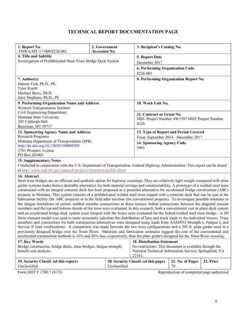
TECHNICAL REPORT DOCUMENTATION PAGE
1. Report No. 2. Government
FHWA/MT-17-009/8226-001 Accession No.
3. Recipient's Catalog No.
4. Title and Subtitle
Investigation of Prefabricated Steel-Truss Bridge Deck System
5. Report Date
December 2017
6. Performing Organization Code
8226-001
7. Author(s)
Damon Fick, Ph.D., PE Tyler Kuehl Michael Berry, Ph.D. Jerry Stephens, Ph.D.,
PE
8. Performing Organization Report No.
9. Performing Organization Name and Address
Western Transportation Institute Civil Engineering Department Montana State
University 205 Cobleigh Hall Bozeman, MT 59717
10. Work Unit No.
11. Contract or Grant No.
MSU Project Number 4W5107 MDT Project Number 8226
12. Sponsoring Agency Name and Address
Research Programs
285.
Montana Department of Transportation (SPR)http://dx.doi.org/10.13039/100009209 2701 Prospect Avenue PO Box 201001
13. Type of Report and Period Covered
Final, September 2014 - December 2017
14. Sponsoring Agency Code
5401
15. Supplementary Notes
Conducted in cooperation with the U.S. Department of Transportation, Federal
Highway Administration. This report can be found at
http://www.mdt.mt.gov/research/projects/structures/prefab.shtml
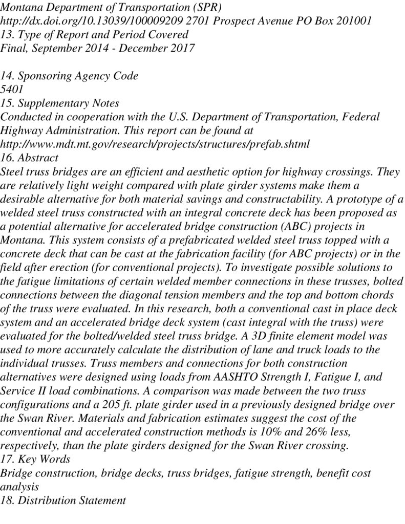
16. Abstract
Steel truss bridges are an efficient and aesthetic option for highway crossings. They
are relatively light weight compared with plate girder systems make them a
desirable alternative for both material savings and constructability. A prototype of a
welded steel truss constructed with an integral concrete deck has been proposed as
a potential alternative for accelerated bridge construction (ABC) projects in
Montana. This system consists of a prefabricated welded steel truss topped with a
concrete deck that can be cast at the fabrication facility (for ABC projects) or in the
field after erection (for conventional projects). To investigate possible solutions to
the fatigue limitations of certain welded member connections in these trusses, bolted
connections between the diagonal tension members and the top and bottom chords
of the truss were evaluated. In this research, both a conventional cast in place deck
system and an accelerated bridge deck system (cast integral with the truss) were
evaluated for the bolted/welded steel truss bridge. A 3D finite element model was
used to more accurately calculate the distribution of lane and truck loads to the
individual trusses. Truss members and connections for both construction
alternatives were designed using loads from AASHTO Strength I, Fatigue I, and
Service II load combinations. A comparison was made between the two truss
configurations and a 205 ft. plate girder used in a previously designed bridge over
the Swan River. Materials and fabrication estimates suggest the cost of the
conventional and accelerated construction methods is 10% and 26% less,
respectively, than the plate girders designed for the Swan River crossing.
17. Key Words
Bridge construction, bridge decks, truss bridges, fatigue strength, benefit cost
analysis
18. Distribution Statement
286.
No restrictions. This document is available through the National TechnicalInformation Service, Springfield, VA 22161.
19. Security Classif. (of this report) 20. Security Classif. (of this page) 21. No. of
Pages 22. Price
Unclassified Unclassified 70
Form DOT F 1700.7 (8-72)
Reproduction of completed page authorized
Disclaimer Statement
This document is disseminated under the sponsorship of the Montana Department of
Transportation (MDT) and the United States Department of Transportation
(USDOT) in the interest of information exchange. The State of Montana and the
United States assume no liability for the use or misuse of its contents.
The contents of this document reflect the views of the authors, who are solely
responsible for the facts and accuracy of the data presented herein. The contents do
not necessarily reflect the views or official policies of MDT or the USDOT.
The State of Montana and the United States do not endorse products of
manufacturers. This document does not constitute a standard, specification, policy
or regulation.
Alternative Format Statement
MDT attempts to provide accommodations for any known disability that may
interfere with a person participating in any service, program, or activity of the
Department. Alternative accessible formats of this information will be provided
upon request. For further information, call 406/444.7693, TTY 800/335.7592, or
Montana Relay at 711.
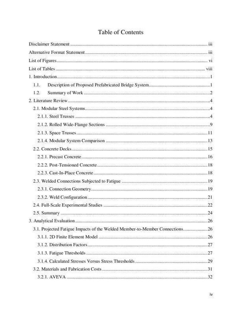
Table of Contents
Disclaimer Statement iii
Alternative Format Statement
iii
List of Figuresvi
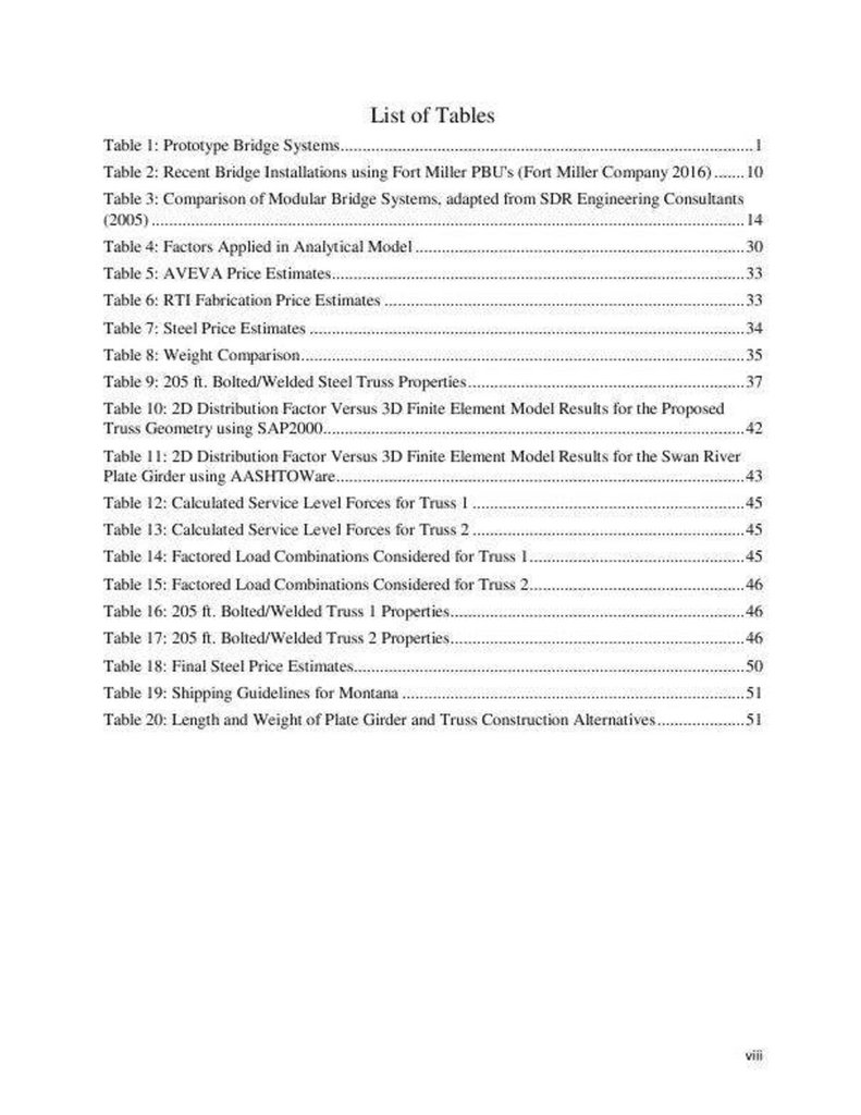
List of Tables viii
1. Introduction
1
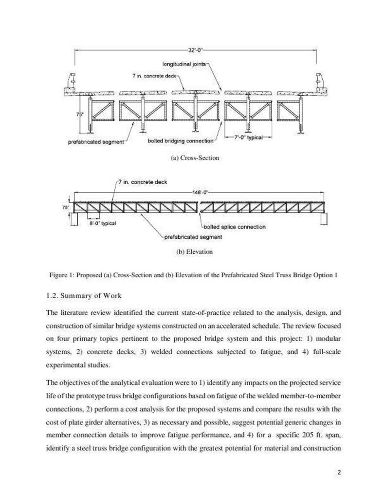
1.1. Description of Proposed Prefabricated Bridge System 1
1.2. Summary of Work 2
2. Literature Review
4
2.1. Modular Steel Systems 4
2.1.1. Steel Trusses 4
2.1.2. Rolled Wide-Flange Sections
9
2.1.3. Space Trusses
11
287.
2.1.4. Modular System Comparison13
2.2. Concrete Decks
15
2.2.1. Precast Concrete 16
2.2.2. Post-Tensioned Concrete 18
2.2.3. Cast-In-Place Concrete
18
2.3. Welded Connections Subjected to Fatigue 19
2.3.1. Connection Geometry 19
2.3.2. Weld Configuration 21
2.4. Full-Scale Experimental Studies 22
2.5. Summary 24
3. Analytical Evaluation 26
3.1. Projected Fatigue Impacts of the Welded Member-to-Member Connections
26
3.1.1. 2D Finite Element Model 26
3.1.2. Distribution Factors 27
3.1.3. Fatigue Thresholds
27
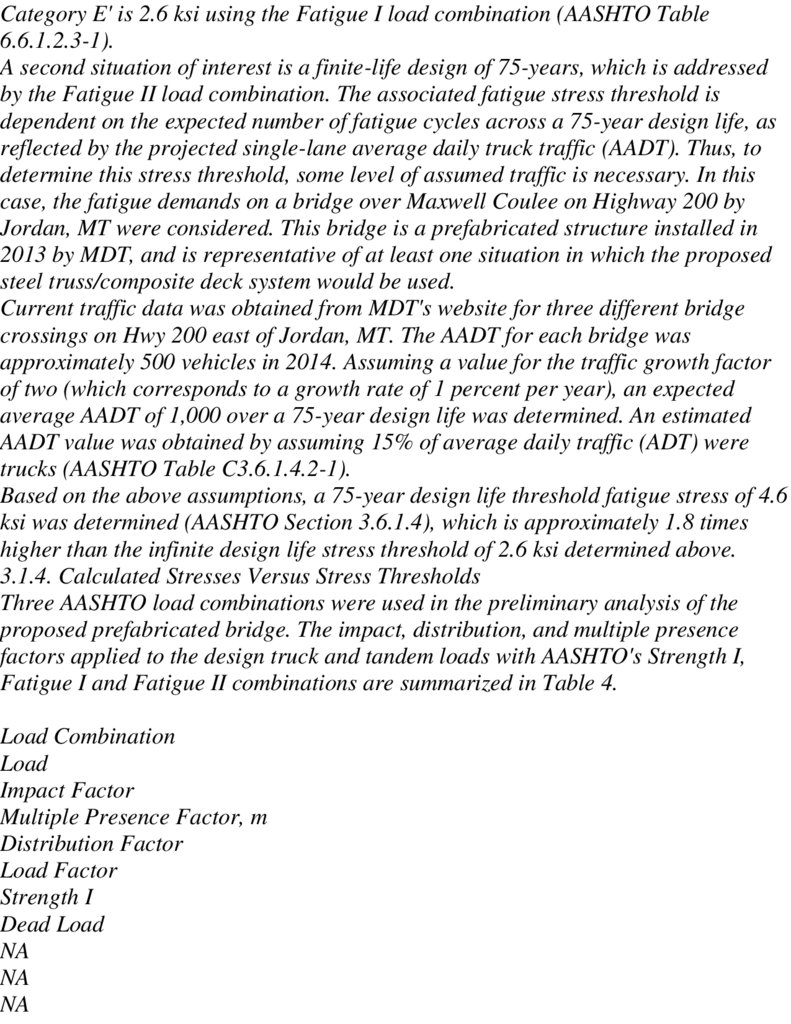
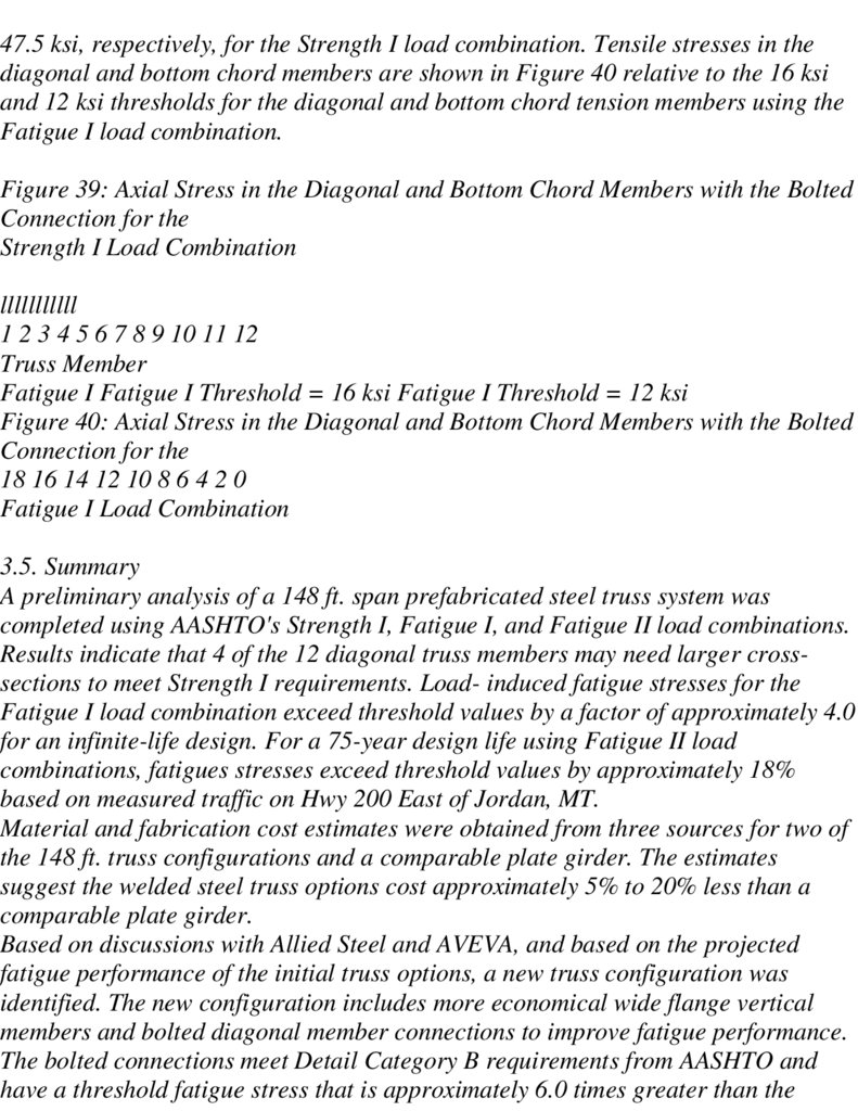
3.1.4. Calculated Stresses Versus Stress Thresholds 29
3.2. Materials and Fabrication Costs 31
3.2.1. AVEVA 32
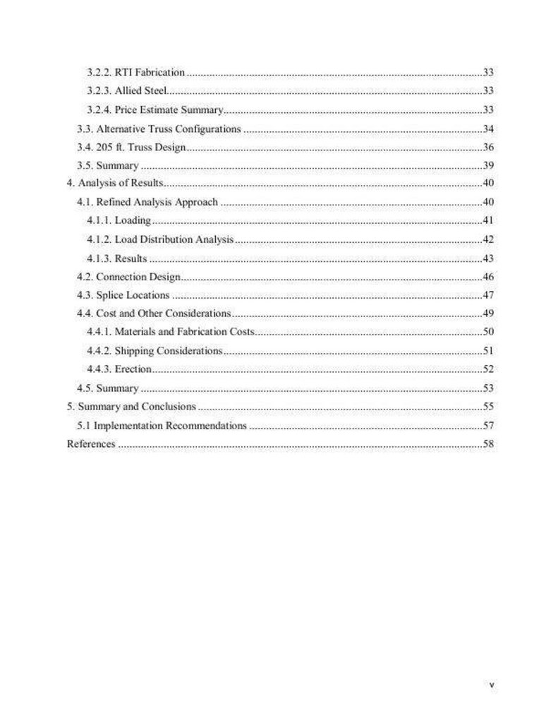
3.2.2. RTI Fabrication 33
3.2.3. Allied Steel 33
3.2.4. Price Estimate Summary 33
3.3. Alternative Truss Configurations 34
3.4. 205 ft. Truss Design
36
3.5. Summary 39
4. Analysis of Results 40
4.1. Refined Analysis Approach 40
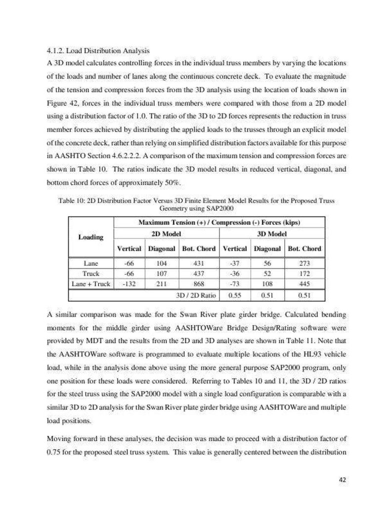
4.1.1. Loading 41
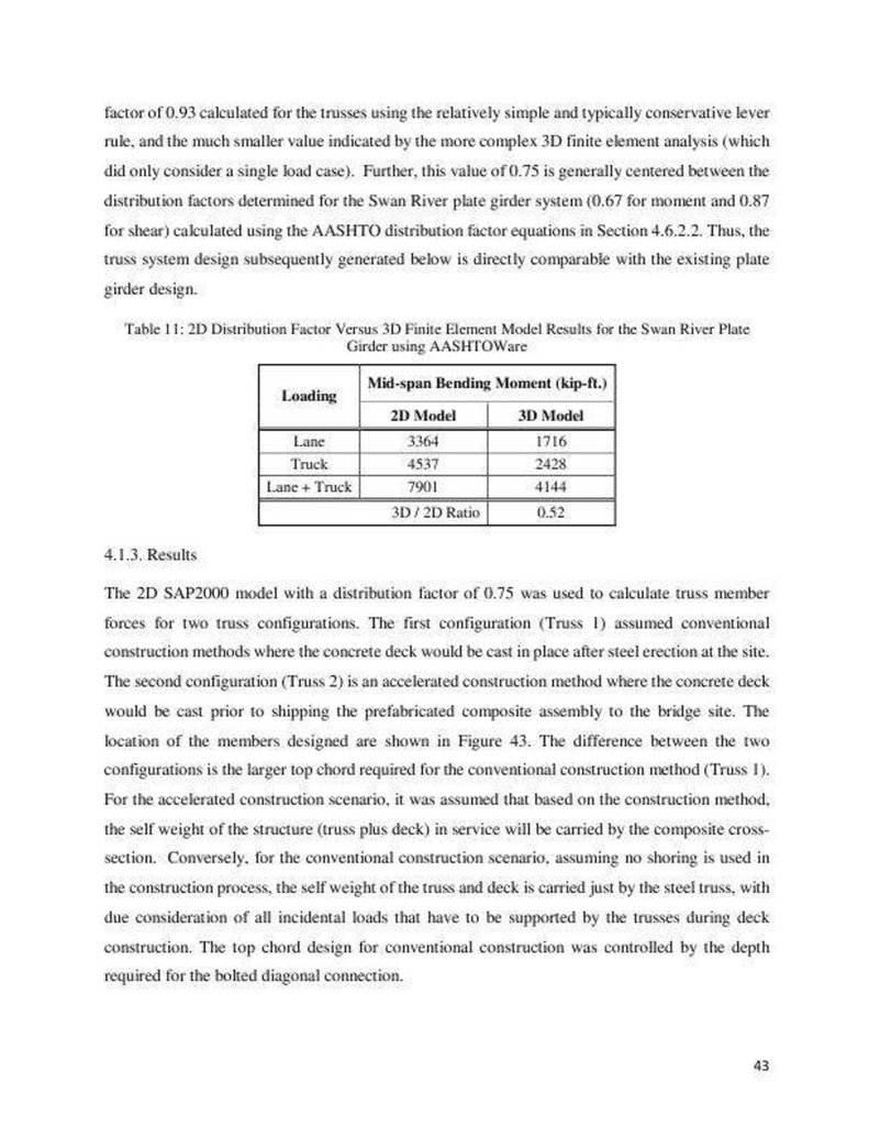
4.1.2. Load Distribution Analysis 42
4.1.3. Results 43
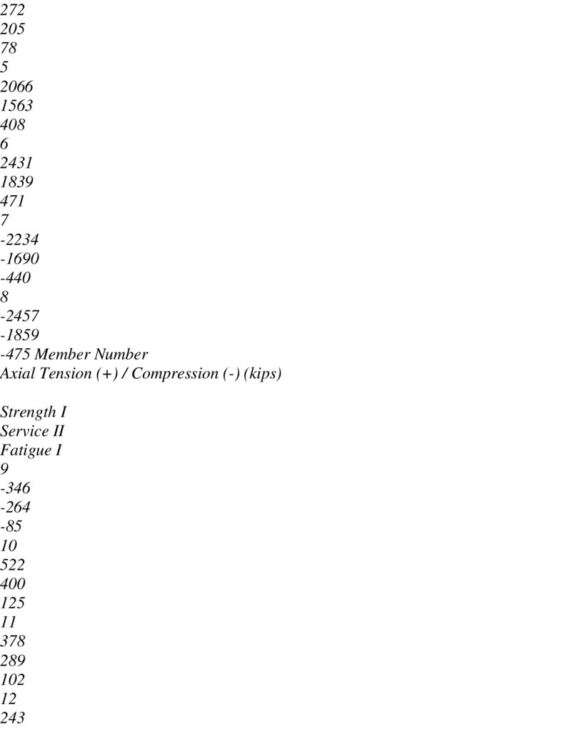
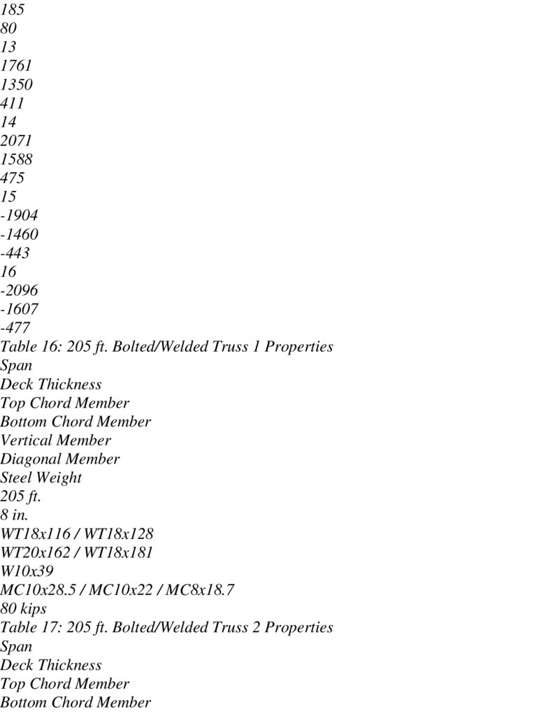
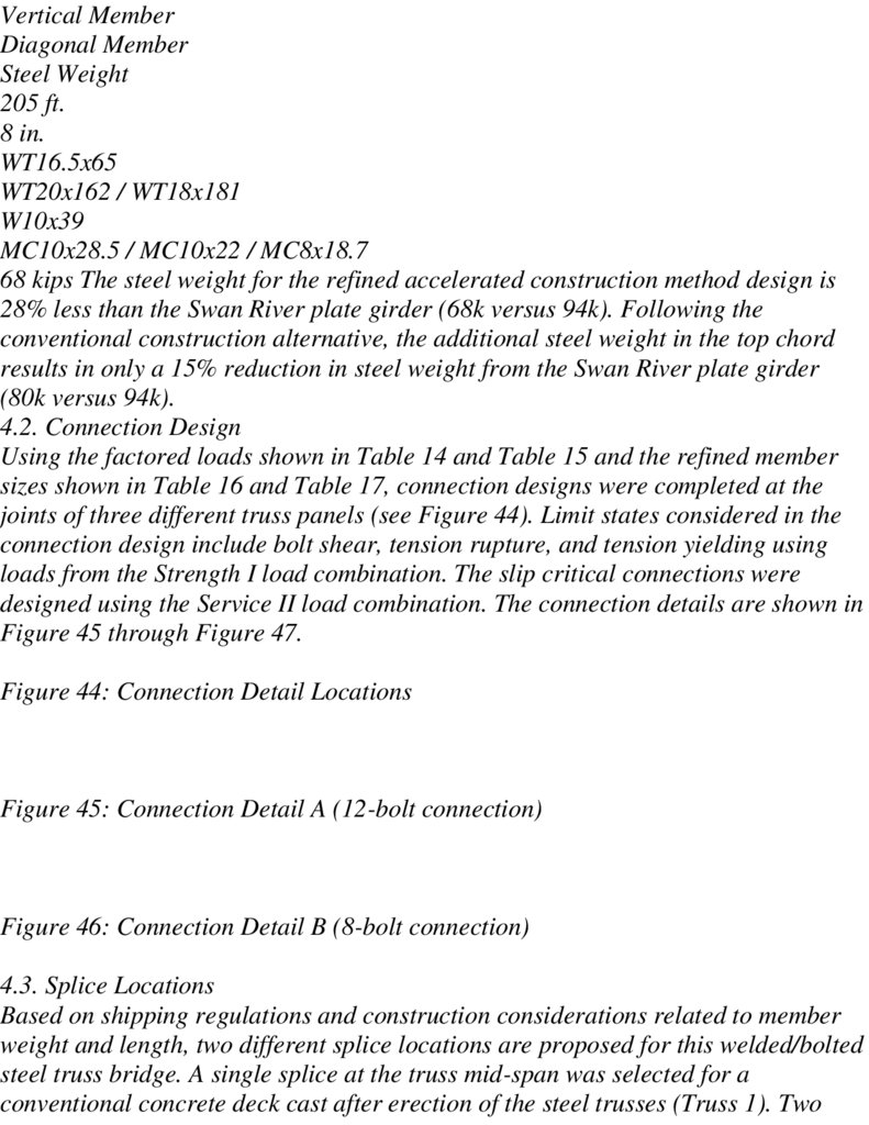
4.2. Connection Design 46
4.3. Splice Locations 47
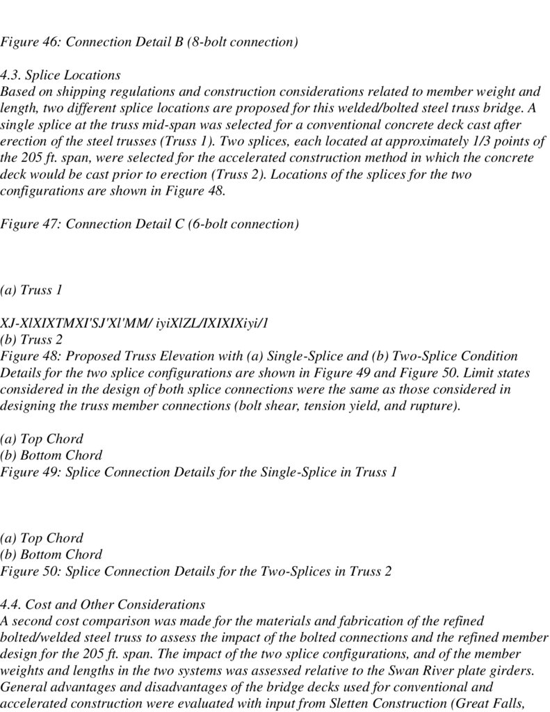
4.4. Cost and Other Considerations 49
4.4.1. Materials and Fabrication Costs 50
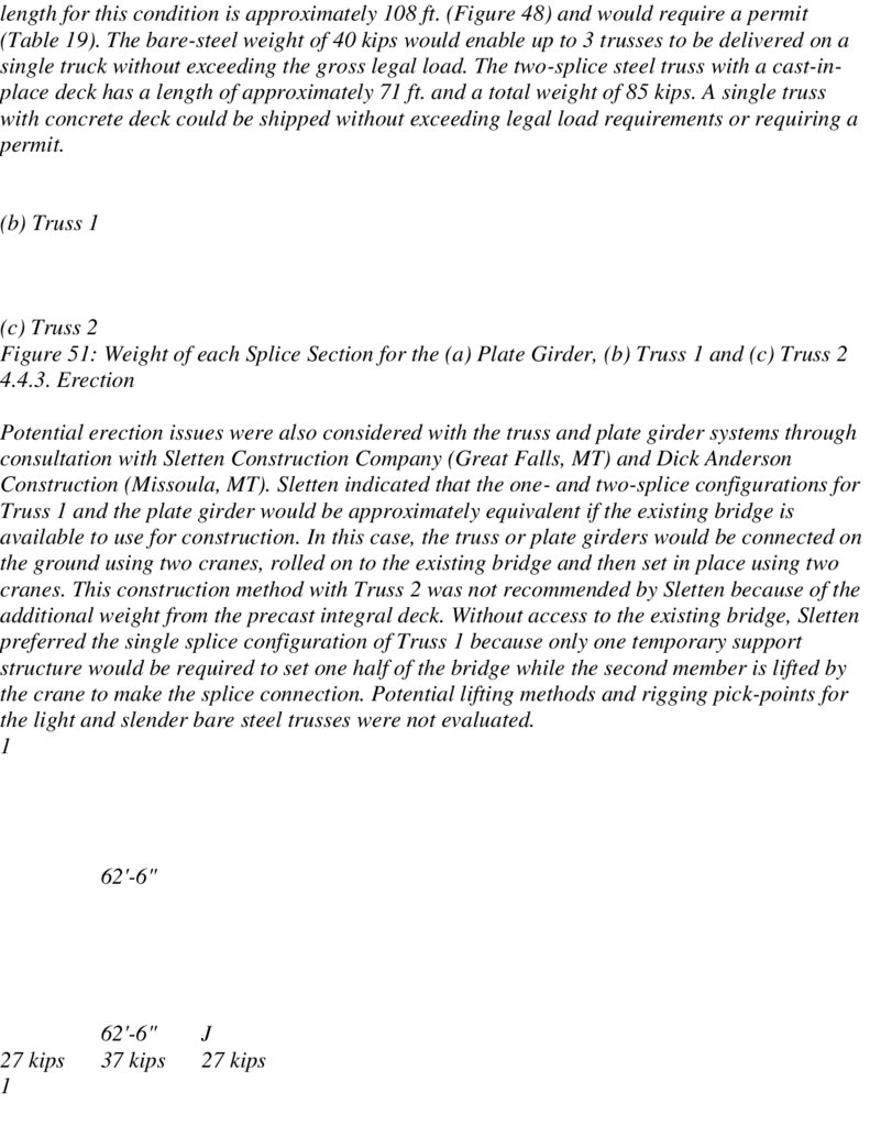
4.4.2. Shipping Considerations 51
4.4.3. Erection
52
4.5. Summary 53
5. Summary and Conclusions 55
288.
5.1 Implementation Recommendations 57References
58
List of Figures
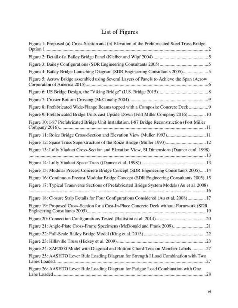
Figure 1: Proposed (a) Cross-Section and (b) Elevation of the Prefabricated Steel
Truss Bridge Option 1 2
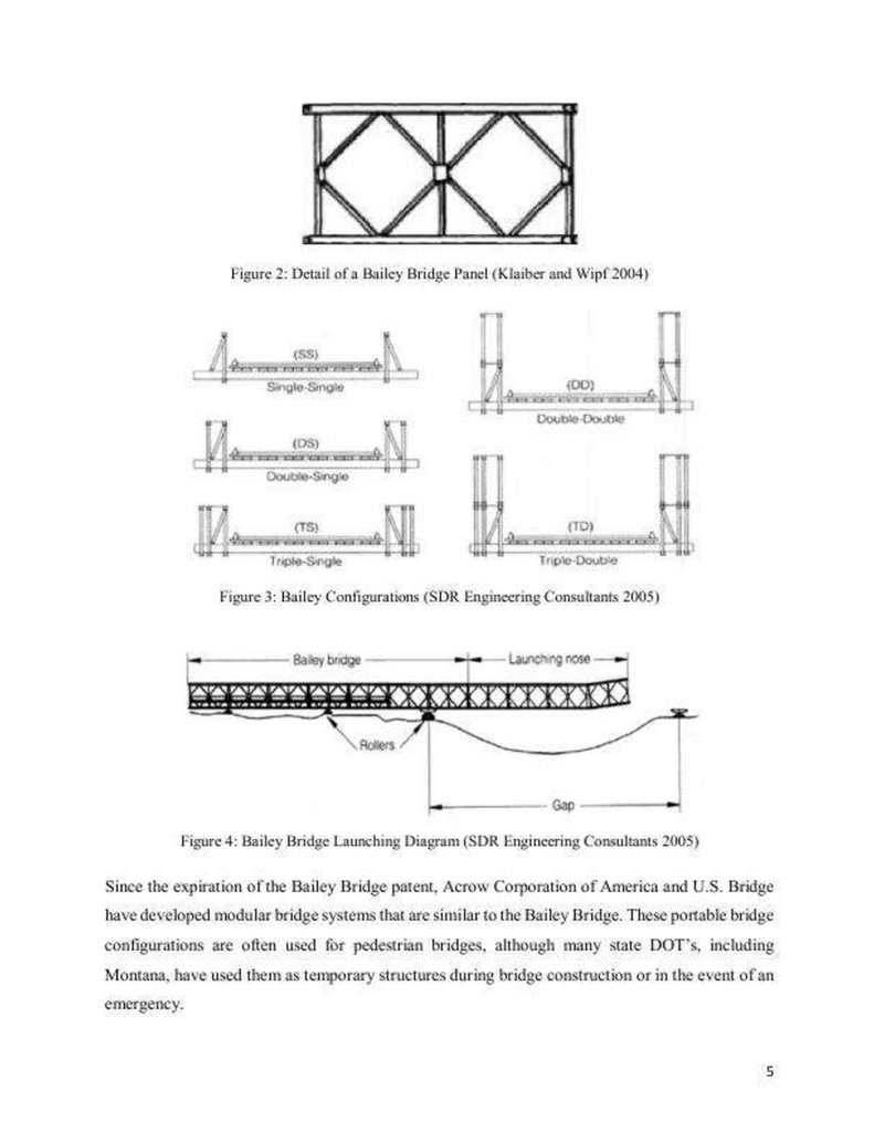
Figure 2: Detail of a Bailey Bridge Panel (Klaiber and Wipf 2004) 5
Figure 3: Bailey Configurations (SDR Engineering Consultants 2005) 5
Figure 4: Bailey Bridge Launching Diagram (SDR Engineering Consultants 2005) 5
Figure 5: Acrow Bridge assembled using Several Layers of Panels to Achieve the
Span (Acrow Corporation of America 2015)6
Figure 6: US Bridge Design, the "Viking Bridge" (U.S. Bridge 2015)
8
Figure 7: Crosier Bottom Crossing (McConahy 2004)
9
Figure 8: Prefabricated Wide-Flange Beams topped with a Composite Concrete
Deck
9
Figure 9: Prefabricated Bridge Units cast Upside-Down (Fort Miller Company
2016)
10
Figure 10: I-87 Prefabricated Bridge Unit Installation, I-87 Bridge Reconstruction
(Fort Miller Company 2016) 11
Figure 11: Roize Bridge Cross-Section and Elevation View (Muller 1993)
11
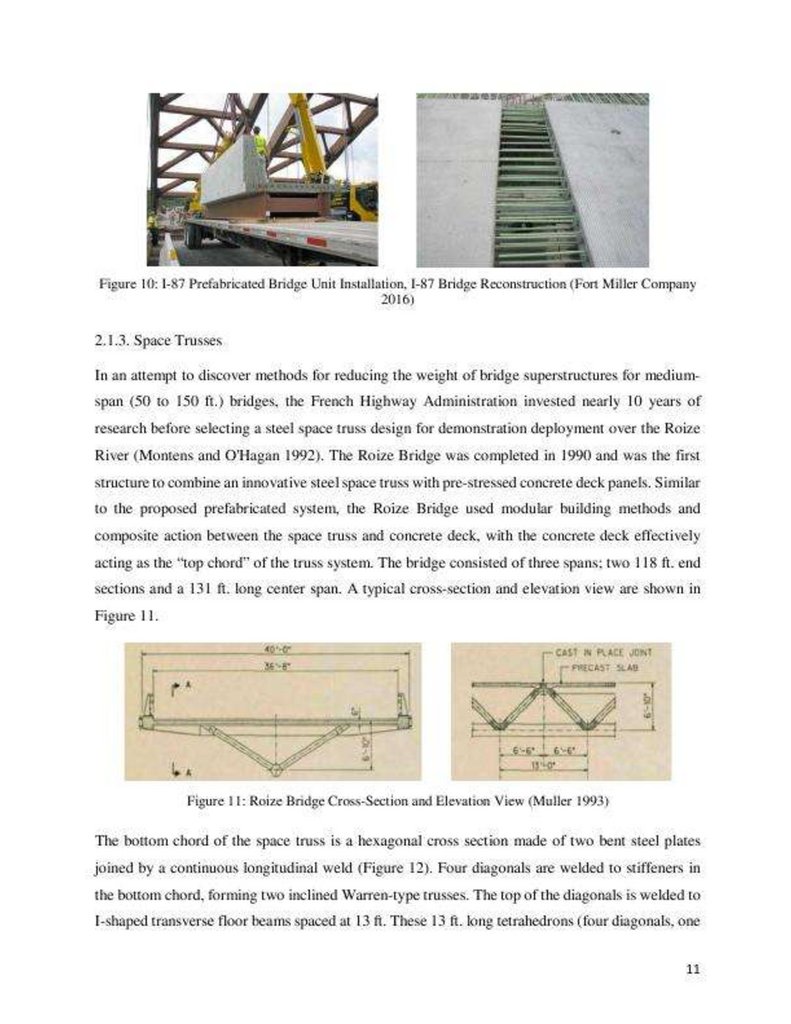
Figure 12: Space Truss Superstructure of the Roize Bridge (Muller 1993) 12
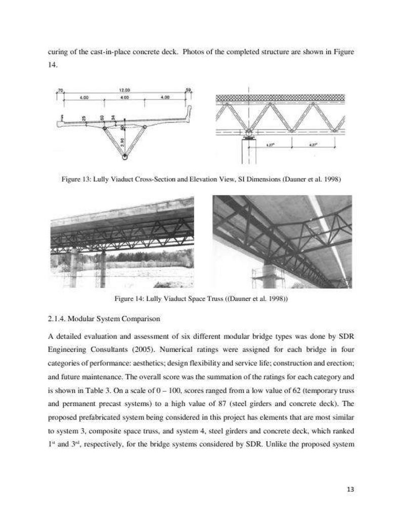
Figure 13: Lully Viaduct Cross-Section and Elevation View, SI Dimensions (Dauner
et al. 1998) 13
Figure 14: Lully Viaduct Space Truss ((Dauner et al. 1998)) 13
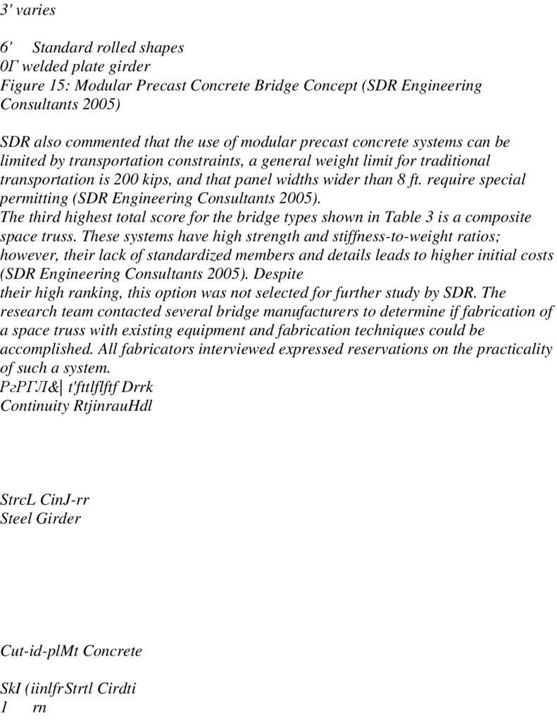
Figure 15: Modular Precast Concrete Bridge Concept (SDR Engineering
Consultants 2005) 14
Figure 16: Continuous Precast Modular Bridge Concept (SDR Engineering
Consultants 2005) . 15
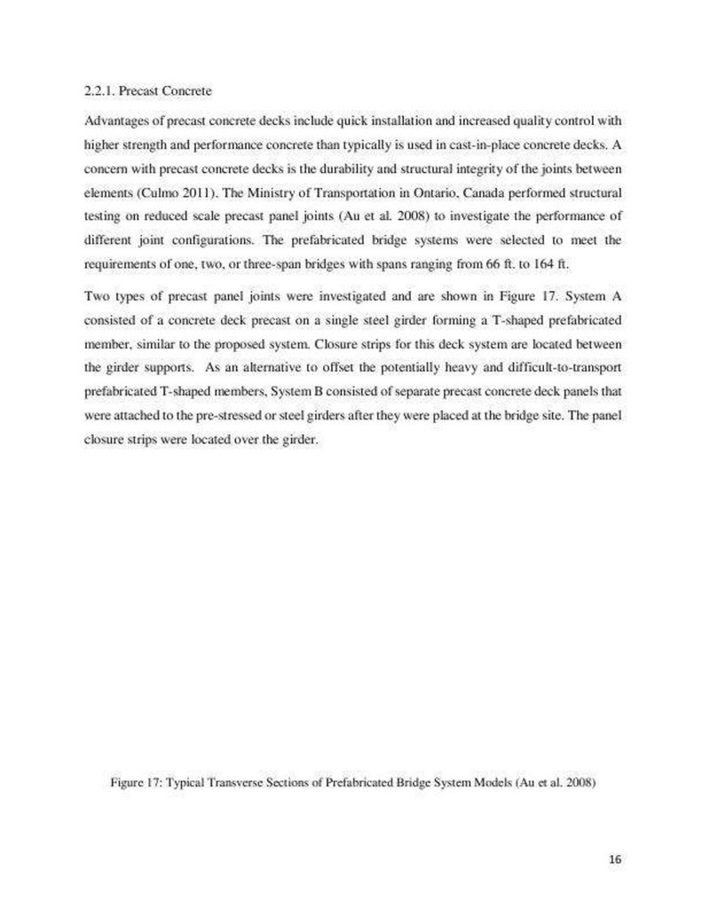
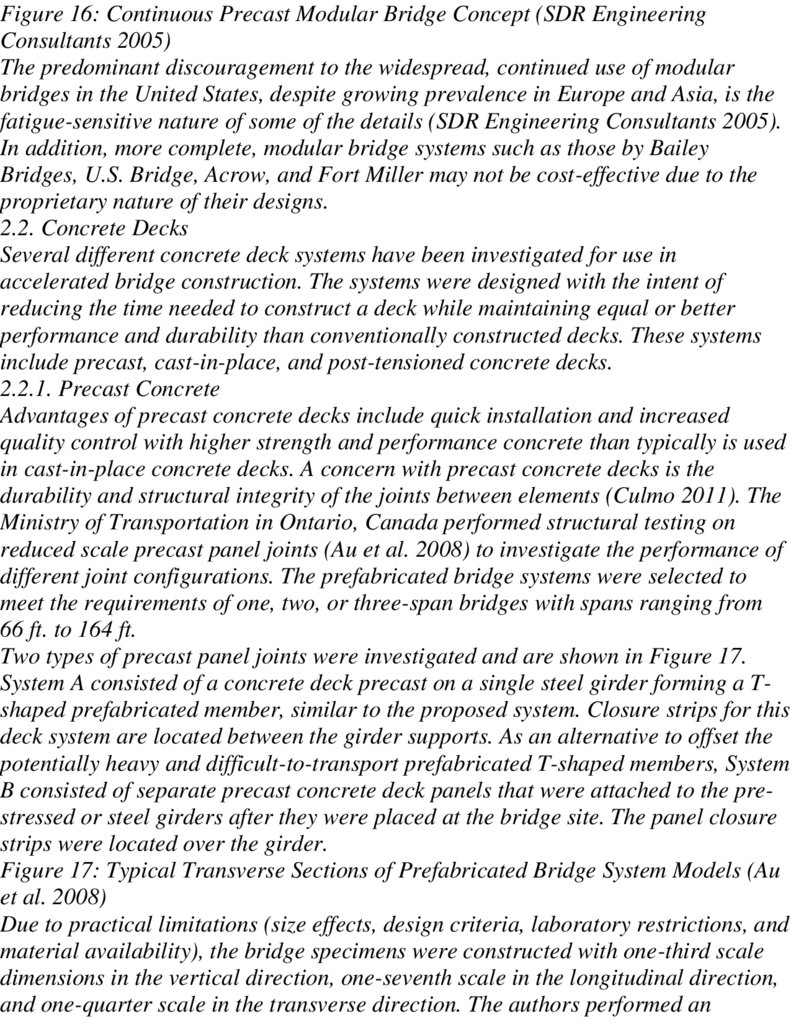
Figure 17: Typical Transverse Sections of Prefabricated Bridge System Models (Au
et al. 2008) 16
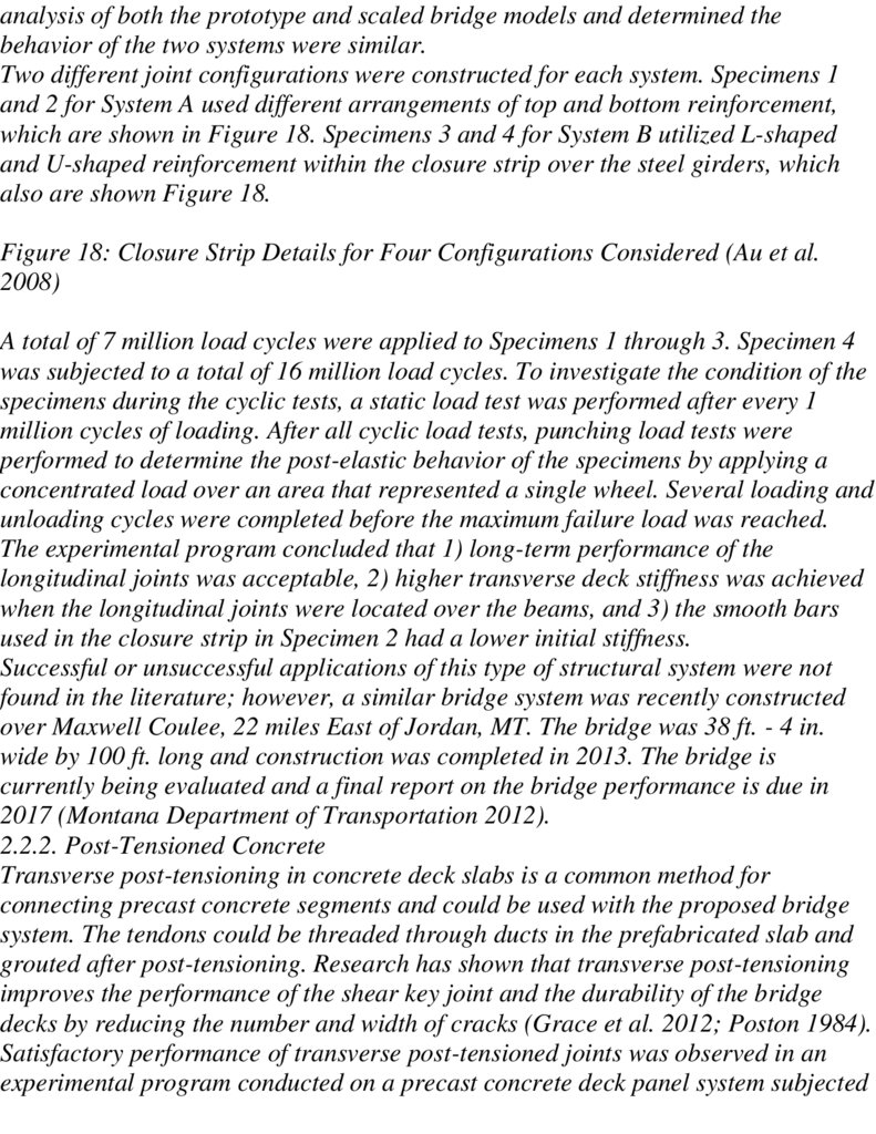
Figure 18: Closure Strip Details for Four Configurations Considered (Au et al.
2008)
17
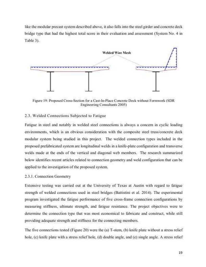
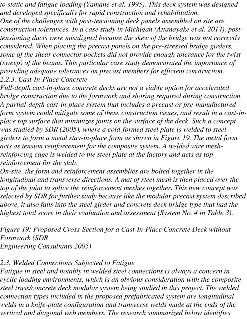
Figure 19: Proposed Cross-Section for a Cast-In-Place Concrete Deck without
Formwork (SDR Engineering Consultants 2005) 19
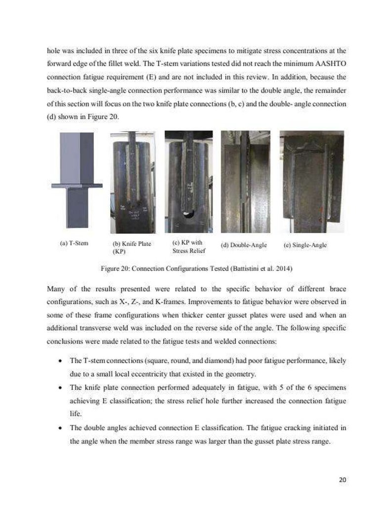
Figure 20: Connection Configurations Tested (Battistini et al. 2014) 20
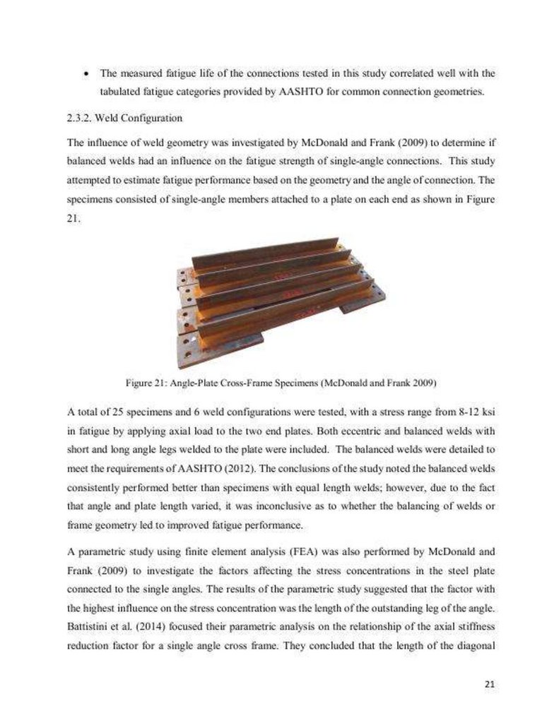
Figure 21: Angle-Plate Cross-Frame Specimens (McDonald and Frank 2009) 21
Figure 22: Full-Scale Bailey Bridge Model (King et al. 2013) 22
Figure 23: Hillsville Truss (Hickey et al. 2009) 23
289.
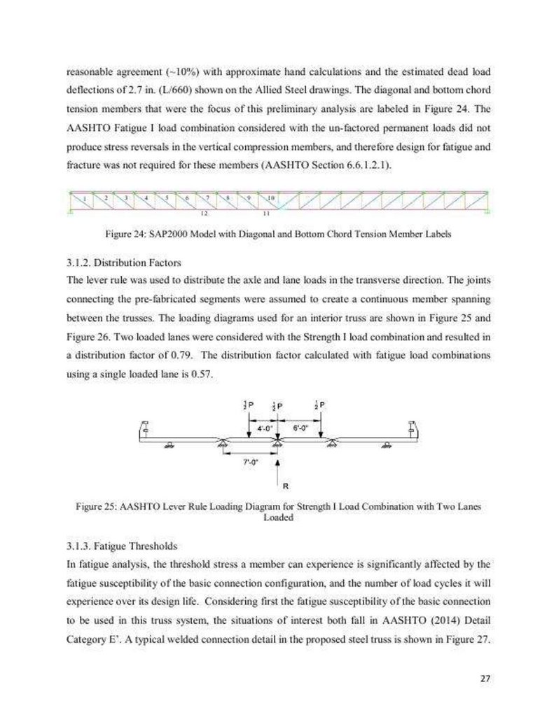
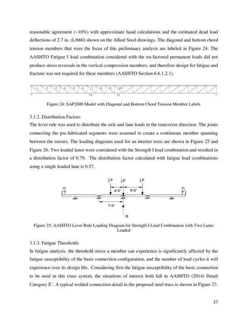
Figure 24: SAP2000 Model with Diagonal and Bottom Chord Tension MemberLabels 27
Figure 25: AASHTO Lever Rule Loading Diagram for Strength I Load Combination
with Two Lanes Loaded 27
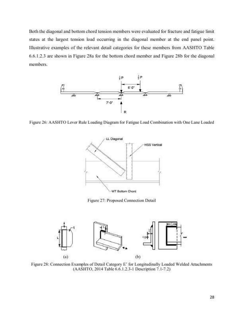
Figure 26: AASHTO Lever Rule Loading Diagram for Fatigue Load Combination
with One Lane Loaded 28
Figure 27: Proposed Connection Detail
28
Figure 28: Connection Examples of Detail Category E' for Longitudinally Loaded
Welded Attachments (AASHTO, 2014 Table 6.6.1.2.3-1 Description 7.1-7.2) 28
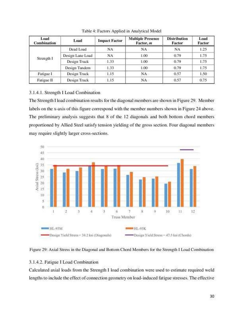
Figure 29: Axial Stress in the Diagonal and Bottom Chord Members for the
Strength I Load Combination 30
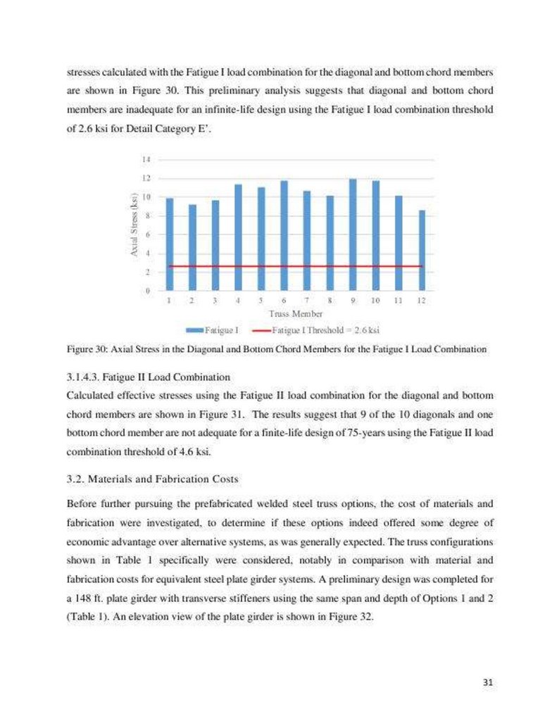
Figure 30: Axial Stress in the Diagonal and Bottom Chord Members for the Fatigue
I Load Combination
31
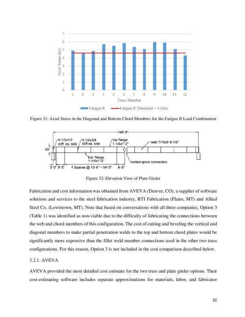
Figure 31: Axial Stress in the Diagonal and Bottom Chord Members for the Fatigue
II Load Combination 32
Figure 32: Elevation View of Plate Girder 32
Figure 33: Diagonal Member Connection Examples of Detail Category B for
Longitudinally Loaded Bolted Attachments (AASHTO 2014 Table 6.6.1.2.3-1
Description 2.5) 34
Figure 34: Example of Detail Category C' for Longitudinally Loaded Bottom Chord
with Transverse Welded Attachments (AASHTO, 2014 Table 6.6.1.2.3-1 Description
4.1) 35
Figure 35: Typical Panel Layout of Option 4
35
Figure 36: Comparison of Truss and Plate Girder Weight as Span Changes 36
Figure 37: 205 ft. Bolted/Welded Steel Truss Elevation View 37
Figure 38: Bolted Connection Detail 37
Figure 39: Axial Stress in the Diagonal and Bottom Chord Members with the Bolted
Connection for the Strength I Load Combination 38
Figure 40: Axial Stress in the Diagonal and Bottom Chord Members with the Bolted
Connection for the Fatigue I Load Combination 38
Figure 41: 3D Finite Element Model 41
Figure 42: Location of Uniform Lane Loads and Concentrated Design Truck Loads
for a Two- Lane Condition 41
Figure 43: Location and Designation of Truss Members Designed for (a) Truss 1
using Conventional Construction and (b) Truss 2 using Accelerated Construction
44
Figure 44: Connection Detail Locations
47
Figure 45: Connection Detail A (12-bolt connection) 47
290.
Figure 46: Connection Detail B (8-bolt connection) 47Figure 47: Connection Detail C (6-bolt connection) 48
Figure 48: Proposed Truss Elevation with (a) Single-Splice and (b) Two-Splice
Condition
48
Figure 49: Splice Connection Details for the Single-Splice in Truss 1
49
Figure 50: Splice Connection Details for the Two-Splices in Truss 2 49
Figure 51: Weight of each Splice Section for the (a) Plate Girder, (b) Truss 1 and
(c) Truss 2 ...52
List of Tables
Table 1: Prototype Bridge Systems
1
Table 2: Recent Bridge Installations using Fort Miller PBU's (Fort Miller Company
2016)
10
Table 3: Comparison of Modular Bridge Systems, adapted from SDR Engineering
Consultants (2005)
14
Table 4: Factors Applied in Analytical Model 30
Table 5: AVEVA Price Estimates 33
Table 6: RTI Fabrication Price Estimates 33
Table 7: Steel Price Estimates
34
Table 8: Weight Comparison 35
Table 9: 205 ft. Bolted/Welded Steel Truss Properties 37
Table 10: 2D Distribution Factor Versus 3D Finite Element Model Results for the
Proposed Truss Geometry using SAP2000 42
Table 11: 2D Distribution Factor Versus 3D Finite Element Model Results for the
Swan River Plate Girder using AASHTOWare 43
Table 12: Calculated Service Level Forces for Truss 1
45
Table 13: Calculated Service Level Forces for Truss 2
45
Table 14: Factored Load Combinations Considered for Truss 1 45
Table 15: Factored Load Combinations Considered for Truss 2 46
Table 16: 205 ft. Bolted/Welded Truss 1 Properties 46
Table 17: 205 ft. Bolted/Welded Truss 2 Properties 46
Table 18: Final Steel Price Estimates 50
Table 19: Shipping Guidelines for Montana 51
Table 20: Length and Weight of Plate Girder and Truss Construction Alternatives
51
1. Introduction
This final report summarizes the literature review, analytical evaluation, and
analysis of results for the Prefabricated Steel Truss Bridge Deck Systems project. A
prototype bridge structure has been proposed as a potential alternative for
291.
accelerated bridge construction (ABC) projects in Montana. Accelerated bridgeconstruction is rapidly gaining momentum in the United States as a common bridge
building practice due to the increased safety and decreased impact on the public
that results from the associated reduced construction times. The proposed system
consists of a prefabricated welded steel truss topped with a composite concrete deck
cast-in-place at the fabrication facility. These composite members are transported to
the site, where they are set next to each other on a prepared foundation to create the
bridge.
1.1. Description of Proposed Prefabricated Bridge System
Preliminary designs were completed by Allied Steel for three different prefabricated
steel truss/integral concrete deck bridge systems intended for a 108 ft. bridge over
Big Dry Creek (Jordan, MT) and two configurations of a 148 ft. bridge over Cooper
Creek (Thompson Falls, MT). The prefabricated elements for these systems consist
of a single truss supporting 10 ft. - 4 in. (Big Dry Creek) and 7 ft. (Cooper Creek)
wide concrete decks cast at the steel fabrication facility. Member sizes for these
preliminary designs are shown in Table 1.
Table 1: Prototype Bridge Systems
Option
Span
Deck Thickness
Top Chord Member
Bottom Chord Member
Vertical Member
Diagonal Member
Steel Weight
1
148 ft.
7 in.
WT12x38
WT18x97 / WT20x147
HSS6x6/ HSS5x5
LL5x3 / LL6x3 / LL7x4
29,100 lbs.
2
148 ft.
7 in.
WT12x38
WT18x97 / WT20x147
292.
W8x15-31W6x16 / W8x21-28
28,000 lbs.
3
108 ft.
8-1/4 in.
PL3/4x12
PL1-3/4x12 / PL2x6
W8x18-24
PL1x6
18,080 lbs. In all cases, the vertical and diagonal truss members are welded to the
top and bottom chords of the steel truss. Two (or more) prefabricated elements are
bolted together longitudinally to create the final bridge span. The longitudinal and
transverse joints between the prefabricated elements are reinforced and filled with
concrete to create continuity between the segments. A cross-section and elevation
view of Option 1 is shown in Figure 1.
(a) Cross-Section
(b) Elevation
Figure 1: Proposed (a) Cross-Section and (b) Elevation of the Prefabricated Steel
Truss Bridge Option 1 1.2. Summary of Work
The literature review identified the current state-of-practice related to the analysis,
design, and construction of similar bridge systems constructed on an accelerated
schedule. The review focused on four primary topics pertinent to the proposed
bridge system and this project: 1) modular systems, 2) concrete decks, 3) welded
connections subjected to fatigue, and 4) full-scale experimental studies.
The objectives of the analytical evaluation were to 1) identify any impacts on the
projected service life of the prototype truss bridge configurations based on fatigue of
the welded member-to-member connections, 2) perform a cost analysis for the
proposed systems and compare the results with the cost of plate girder alternatives,
3) as necessary and possible, suggest potential generic changes in member
connection details to improve fatigue performance, and 4) for a specific 205 ft. span,
identify a steel truss bridge configuration with the greatest potential for material
and construction efficiencies. The 205 ft. span was selected so that these results
293.
could be readily compared with the Swan River plate girder project currently beingdesigned by MDT.
A bolted/welded prefabricated steel truss bridge was investigated as an alternative
to the welded truss bridge. Use of bolted connections at selected locations in the
trusses offers improved fatigue performance, allowing for lighter weight members,
and making it a viable alternative for bridge replacement projects using either
conventional or accelerated construction methods. The proposed system consists of
bolted diagonal and welded vertical member connections to the top and bottom
chords. Work completed includes 1) development of a 3D finite element model used
to more accurately calculate the distribution of lane and truck loads to the truss
members, 2) determination of member sizes and connection geometry to satisfy
AASHTO Strength I, Fatigue I, and Service II load combinations for both
conventional and accelerated construction methods, and 3) estimation of potential
cost savings related to materials, fabrication, and construction of these alternatives
compared with the 205 ft. Swan River plate girders.
2. Literature Review
In reviewing prefabricated bridge systems with a view toward investigating their
deployment, four subject areas of interest were identified and researched in the
literature: 1) modular steel systems, 2) concrete decks, 3) welded connections
subjected to fatigue, and 4) full-scale experimental studies. Each topic, discussed in
the following subsections, was selected for its impact on the analysis, design and
construction of a prefabricated steel-truss bridge in Montana.
With these topics in mind, a thorough search was performed using four resource
databases: Engineering Village, MDT Library, Transportation Research Board, and
Google Scholar. The keyword "Prefabricated Bridges" was successfully combined
with "Steel Truss," and "Deck Systems" to identify potential works of interest. The
articles were reviewed and further organized into categories related to the
components of the proposed modular steel system. This review and filtering process
identified 22 sources (journal publications, trade journal articles, and state, federal,
and private reports) as the most relevant to the proposed prefabricated steel truss
bridge.
2.1. Modular Steel Systems
Prefabricated steel bridges have been constructed using a truss configuration, most
notably in the Bailey Bridge and its successors. Other prefabricated steel systems
include steel girders with composite concrete decks and composite space trusses.
2.1.1. Steel Trusses
One of the earliest forms of prefabricated bridges was the Bailey Bridge. Patented
in 1943, the Bailey Bridge was designed by Sir Donald Bailey for use by the Allied
294.
Forces to build crossings during World War II (SDR Engineering Consultants2005). A typical longitudinal section of a Bailey Bridge is shown in Figure 2. This
section has a width of 10 ft. and a height of 4 ft. - 9 in. These sections, designed to fit
in a standard military truck, are bolted together in the field at the top and bottom
chords to form a through-truss bridge. Five different steel bridge configurations are
available, using Standard Bailey Bridge System components (Figure 3).
Constructing the Bailey Bridge can be done using a crane to hoist the assembled
configuration in place or launching the structure from one side of the gap to be
bridged as shown in Figure 4. Portable Bailey panel bridges are currently available
from Bailey Bridges, Inc.
Figure 2: Detail of a Bailey Bridge Panel (Klaiber and Wipf 2004)
Figure 3: Bailey Configurations (SDR Engineering Consultants 2005)
Figure 4: Bailey Bridge Launching Diagram (SDR Engineering Consultants 2005)
Since the expiration of the Bailey Bridge patent, Acrow Corporation of America and
U.S. Bridge have developed modular bridge systems that are similar to the Bailey
Bridge. These portable bridge configurations are often used for pedestrian bridges,
although many state DOT's, including Montana, have used them as temporary
structures during bridge construction or in the event of an emergency.
The Acrow Panel Bridge is made up of three different stock items that are assembled
to form the desired configuration. A photo of an Acrow bridge is shown in Figure 5.
The truss segments are 10 ft. wide, 7.2 ft. tall, and 6.5 in. wide. Spans of up to 230 ft.
can be created by bolting the panels together and are capable of supporting three
lanes of HS 25 load. Standard floor beams span between the trusses and decking
panels span longitudinally along the bridge length between the floor beams.
Prefabricated steel orthotropic panels are the most common deck type, although
steel grids and timber options can be incorporated (Klaiber and Wipf 2004).
Figure 5: Acrow Bridge assembled using Several Layers of Panels to Achieve the
Span (Acrow
Corporation of America 2015)
295.
The Bailey Bridge System has been used in Montana for several temporarycrossings where bridges were damaged, deteriorated, or collapsed. A search of
Montana's Treasure State Endowment Program (TSEP) project applications and
reports, the Department of Commerce project evaluations and funding
recommendations, and the Department of Transportation bid packages revealed the
following projects used prefabricated steel bridges (State of Montana 2016):
• A 100 ft. span, double-single M2 Bailey Bridge configuration was installed over
the existing bridge structure crossing Box Elder Creek, near Hammond, MT. Bids
were received in August 2009 to replace the temporary structure with a permanent
one.
• Park County installed a temporary Bailey Bridge to replace the Ninth Street
Bridge over the Yellowstone River in June 2008, in Livingston. The bridge was
installed over the existing structure and was posted with a speed limit of 5 mph and
a maximum vehicle weight of 3 tons.
• A collapsed bridge over Fish Creek near Ryegate, in Golden Valley County, was
replaced with a temporary Bailey Bridge. Bids were received in August 2014 to
replace the temporary structure with 83 ft. pre-stressed bulb-tee beams.
• TSEP emergency funds were used to construct a temporary Bailey Bridge over a
damaged bridge crossing Racetrack Creek in Powell County (pre-2005)
• Mineral County used a temporary Bailey Bridge over the 52 ft. damaged timber
Cedar Creek Bridge (pre-2005).
• In December of 2002, Madison County installed a Bailey Bridge over the
deteriorating Upper South Boulder Bridge to provide a temporary crossing until a
permanent solution could be implemented.
The panel sizes, span lengths, and load capacities of the Bailey type bridges are
consistent with the proposed systems considered in this investigation. Their long
history demonstrates that modular prefabricated truss systems are an effective
bridge construction strategy. That being said, these bridges are used in a through
truss configuration, while the proposed systems use an underslung truss
arrangement. The decks in these systems do not act compositely with the trusses,
while composite action between the concrete decks and steel trusses in the proposed
systems is expected to offer improved structural efficiency and stiffness.
U.S. Bridge, a descendent of the Ohio Bridge Corporation, offers prefabricated
truss options that are designed for the Association of State Highway and
Transportation Officials (AASHTO) HS10, HS15, HS25, and HL93 loadings (U.S.
Bridge 2015). Unlike the Bailey/Acrow Panel Bridge, where identical panel
segments are bolted together in the field, the U.S. Bridge System uses longer, all-
296.
welded truss systems that can then be bolted together in the field. The trusses panelsare prefabricated with standard W-sections and the entire welded segments are then
hot-dipped galvanized (Klaiber and Wipf 2004). The trusses are through-type with
parallel top and bottom chords and are available in standard lengths of up to 150 ft.
For longer spans, a camel back configuration is used and is shown in Figure 6. A
common deck system includes underslung floor beams carrying simply supported
stringers. Traditional concrete filled pans and timber decks can also be provided.
Figure 6: US Bridge Design, the "Viking Bridge" (U.S. Bridge 2015)
Completely prefabricating steel-truss bridge superstructures could potentially be a
more cost- effective and permanent solution for counties that install temporary
bridge structures. Albany County in New York State investigated this alternative to
find cost-efficient bridge solutions in rural areas with lower traffic volumes (Heine
1990). The county replaced a 70 ft. truss bridge built in 1898 with Warren trusses
and welded connections prefabricated by the Ohio Bridge Corporation. The
estimated cost to install the bridge on the existing abutments was $50 per sq. ft. and
included the cost of material, erection, and placement of a wooden deck. Bid prices
were 5 to 6 times this amount for a standard replacement (Heine 1990).
A second example of a permanent welded prefabricated truss installation is the
Crosier Bottom culvert in Meade County, Kentucky (McConahy 2004). The solution
for the bridge replacement was a design-build process using 80 ft. prefabricated
steel trusses (Figure 7). This alternative was substantially cheaper than a cast-inplace concrete bridge (McConahy 2004). The steel trusses were a U.S. Bridge
product, and each truss was shipped in two 40-foot sections that were bolted
together to form the final 80 ft. length and then lifted by crane onto the abutments.
The bridge was finished with a cast-in-place concrete deck. The entire project,
including a soil investigation, design, and construction was 30 days. A detailed
timeline of the construction was not provided. The Crosier Bottom bridge
replacement highlights the benefits that prefabricated steel trusses can provide.
Figure 7: Crosier Bottom Crossing (McConahy 2004) 2.1.2. Rolled Wide-Flange
Sections
Another type of prefabricated modular system consists of wide-flange beams topped
with a composite concrete deck, as shown in Figure 8. One such system, originally
patented under the name "Inverset," is now marketed by Fort Miller Co., Inc.
(Schuylerville, NY) as Prefabricated Bridge Units (PBU). The composite system is
297.
similar to the proposed prefabricated system of the current study; however, theassemblies consist of two wide-flange sections, rather than steel trusses, topped with
a concrete deck. Common or typical segment sizes are not provided on Fort Miller
Company's website.
Figure 8: Prefabricated Wide-Flange Beams topped with a Composite Concrete
Deck
The PBU/Inverset system uses an innovative fabrication method to obtain a more
efficient composite cross-section. The segments are cast in an upside down
orientation, as shown in Figure 9, in such a manner that upon subsequent erection,
stresses in the composite elements are near zero in the bottom steel flange and are
tensile in the top concrete flange (Klaiber and Wipf 2004). The result is a more
efficient section for short to medium span bridges where stresses are dominated by
live loading. The Fort Miller PBU's have been used for spans up to 126 ft. long with
skews that exceed 45 degrees (Fort Miller Company 2016). The span and width of
the prefabricated segments for this specific case was not provided. Keys cast in the
overhanging slabs are grouted together with non-shrink grout during construction.
A similar joint system was investigated by Au et al. (2008) and is discussed in the
following section of this report.
Figure 9: Prefabricated Bridge Units cast Upside-Down (Fort Miller Company
2016)
The New York State Department of Transportation used PBUs for the north and
south bound bridges over the Mohawk River to minimize disruptions of the 110,000
vehicles that use these bridges each day. Two hundred and twenty-four
prefabricated assemblies were used, including assemblies with monolithically cast
traffic barriers, which is the same concept proposed for the system considered
herein. High-performance concrete was used for the longitudinal and transverse
joints between modular units. Installation of the prefabricated members and one of
the joints is shown in Figure 10. More recent installations of Fort Miller PBU's are
listed in Table 2.
Table 2: Recent Bridge Installations using Fort Miller PBU's (Fort Miller Company
2016)
Project
Date
No. of Longitudinal Segments
298.
LengthGarden State Parkway, NJ
April 2016
4
53 ft.
Route 28, MA
April 2016
4
90 ft.
Figure 10: I-87 Prefabricated Bridge Unit Installation, I-87 Bridge Reconstruction
(Fort Miller Company
2016)
2.1.3. Space Trusses
In an attempt to discover methods for reducing the weight of bridge superstructures
for medium- span (50 to 150 ft.) bridges, the French Highway Administration
invested nearly 10 years of research before selecting a steel space truss design for
demonstration deployment over the Roize River (Montens and O'Hagan 1992). The
Roize Bridge was completed in 1990 and was the first structure to combine an
innovative steel space truss with pre-stressed concrete deck panels. Similar to the
proposed prefabricated system, the Roize Bridge used modular building methods
and composite action between the space truss and concrete deck, with the concrete
deck effectively acting as the "top chord" of the truss system. The bridge consisted of
three spans; two 118 ft. end sections and a 131 ft. long center span. A typical crosssection and elevation view are shown in Figure 11.
Figure 11: Roize Bridge Cross-Section and Elevation View (Muller 1993)
The bottom chord of the space truss is a hexagonal cross section made of two bent
steel plates joined by a continuous longitudinal weld (Figure 12). Four diagonals
are welded to stiffeners in the bottom chord, forming two inclined Warren-type
trusses. The top of the diagonals is welded to I-shaped transverse floor beams
spaced at 13 ft. These 13 ft. long tetrahedrons (four diagonals, one
bottom chord, and one floor beam) were mass produced in the factory and
assembled on-site. Rigid nodes were created along the bridge deck by extending the
inclined truss members through the transverse floor beams and into the deck closure
pour.
299.
Diagonals forming inclined Warren trussesI-shaped floor beams
External draped
post-tensioned
cables
Hexagonal bottom chord
Figure 12: Space Truss Superstructure of the Roize Bridge (Muller 1993)
The precast concrete deck panels were 40 ft. wide and 12 ft-4 in. in length. The
panels were pre- stressed with 54 - 0.5 in. bonded strands in the longitudinal
direction and post-tensioned with two 4-strand tendons located on either side of the
floor beams after the closure joints were cast. After the bridge deck was assembled
and cast, the superstructure assembly was continuously post- tensioned with five
external draped 12-strand tendons (Figure 12). The concrete was a high- strength
silica-fume with specified compression strength of 11.5 ksi. The combination of
high- strength concrete and draped longitudinal post-tensioning helped reduce the
long-term creep effects due to flexural loads (Montens and O'Hagan 1992).
The Lully Viaduct in Switzerland is a similar composite, prefabricated space truss
bridge that was selected over two pre-stressed concrete box girder alternatives for
its aesthetic qualities (Dauner et al. 1998). A typical cross-section and elevation
view of this bridge is shown in Figure 13. Average spans of the 1000 m bridge were
43 m, and the space truss depth was 2.9 m. Circular pipes were used for all truss
members and resulted in complicated node geometry that created challenges with
cutting and preparing the member ends for full penetration welds. Special
equipment was used to cut the contact and welding surfaces. The prefabricated
space trusses were erected in one-half span lengths (22 m). Longitudinal and
transverse post-tensioning was used after curing of the cast-in-place concrete deck.
Photos of the completed structure are shown in Figure 14.
300.
Figure 13: Lully Viaduct Cross-Section and Elevation View, SI Dimensions (Dauneret al. 1998)
Figure 14: Lully Viaduct Space Truss ((Dauner et al. 1998)) 2.1.4. Modular System
Comparison
A detailed evaluation and assessment of six different modular bridge types was done
by SDR Engineering Consultants (2005). Numerical ratings were assigned for each
bridge in four categories of performance: aesthetics; design flexibility and service
life; construction and erection; and future maintenance. The overall score was the
summation of the ratings for each category and is shown in Table 3. On a scale of 0
- 100, scores ranged from a low value of 62 (temporary truss and permanent precast
systems) to a high value of 87 (steel girders and concrete deck). The proposed
prefabricated system being considered in this project has elements that are most
similar to system 3, composite space truss, and system 4, steel girders and concrete
deck, which ranked 1st and 3rd, respectively, for the bridge systems considered by
SDR. Unlike the proposed system
where the bridge is supported by the bottom chord, the under-slung truss (System 5)
evaluated by SDR was supported by the top chord and was not as modular as the
other bridge types considered.
Table 3: Comparison of Modular Bridge Systems, adapted from SDR Engineering
Consultants (2005)
No.
Bridge Type
Unit Configurations and Aesthetics (30)
Design Flexibility
and 75-Year Service Life (25)
Construction and Erection (25)
Future Maintenance (20)
Total Score (100)
1
Temporary Truss and Permanent Precast System
21
15
18
8
62
2
301.
Railroad Flatcar24
18
24
14
80
3
Composite Space Truss
23
21
17
16
77
4
Steel Girders and Concrete Deck
26
22
23
16
87
5
Under-Slung Truss
17
19
21
13
70
6
Cold-Formed Steel Plate Box
23
16
22
11
72 The highest total score for the performance criteria shown in Table 3 was a
bridge with steel girders with precast composite concrete decks (No. 4). For this
reason, SDR investigated a new modular precast concrete system that is shown in
Figure 15. To reduce live load deflections, SDR's concept could also include
continuity reinforcement at interior supports, as shown in Figure 16.
302.
3' varies6' Standard rolled shapes
0Г welded plate girder
Figure 15: Modular Precast Concrete Bridge Concept (SDR Engineering
Consultants 2005)
SDR also commented that the use of modular precast concrete systems can be
limited by transportation constraints, a general weight limit for traditional
transportation is 200 kips, and that panel widths wider than 8 ft. require special
permitting (SDR Engineering Consultants 2005).
The third highest total score for the bridge types shown in Table 3 is a composite
space truss. These systems have high strength and stiffness-to-weight ratios;
however, their lack of standardized members and details leads to higher initial costs
(SDR Engineering Consultants 2005). Despite
their high ranking, this option was not selected for further study by SDR. The
research team contacted several bridge manufacturers to determine if fabrication of
a space truss with existing equipment and fabrication techniques could be
accomplished. All fabricators interviewed expressed reservations on the practicality
of such a system.
РгРГЛ&| t'fttlflftf Drrk
Continuity RtjinrauHdl
StrcL CinJ-rr
Steel Girder
Cut-id-plMt Concrete
SkI (iinlfr Strtl Cirdti
1 rn
303.
Figure 16: Continuous Precast Modular Bridge Concept (SDR EngineeringConsultants 2005)
The predominant discouragement to the widespread, continued use of modular
bridges in the United States, despite growing prevalence in Europe and Asia, is the
fatigue-sensitive nature of some of the details (SDR Engineering Consultants 2005).
In addition, more complete, modular bridge systems such as those by Bailey
Bridges, U.S. Bridge, Acrow, and Fort Miller may not be cost-effective due to the
proprietary nature of their designs.
2.2. Concrete Decks
Several different concrete deck systems have been investigated for use in
accelerated bridge construction. The systems were designed with the intent of
reducing the time needed to construct a deck while maintaining equal or better
performance and durability than conventionally constructed decks. These systems
include precast, cast-in-place, and post-tensioned concrete decks.
2.2.1. Precast Concrete
Advantages of precast concrete decks include quick installation and increased
quality control with higher strength and performance concrete than typically is used
in cast-in-place concrete decks. A concern with precast concrete decks is the
durability and structural integrity of the joints between elements (Culmo 2011). The
Ministry of Transportation in Ontario, Canada performed structural testing on
reduced scale precast panel joints (Au et al. 2008) to investigate the performance of
different joint configurations. The prefabricated bridge systems were selected to
meet the requirements of one, two, or three-span bridges with spans ranging from
66 ft. to 164 ft.
Two types of precast panel joints were investigated and are shown in Figure 17.
System A consisted of a concrete deck precast on a single steel girder forming a Tshaped prefabricated member, similar to the proposed system. Closure strips for this
deck system are located between the girder supports. As an alternative to offset the
potentially heavy and difficult-to-transport prefabricated T-shaped members, System
B consisted of separate precast concrete deck panels that were attached to the prestressed or steel girders after they were placed at the bridge site. The panel closure
strips were located over the girder.
Figure 17: Typical Transverse Sections of Prefabricated Bridge System Models (Au
et al. 2008)
Due to practical limitations (size effects, design criteria, laboratory restrictions, and
material availability), the bridge specimens were constructed with one-third scale
dimensions in the vertical direction, one-seventh scale in the longitudinal direction,
and one-quarter scale in the transverse direction. The authors performed an
304.
analysis of both the prototype and scaled bridge models and determined thebehavior of the two systems were similar.
Two different joint configurations were constructed for each system. Specimens 1
and 2 for System A used different arrangements of top and bottom reinforcement,
which are shown in Figure 18. Specimens 3 and 4 for System B utilized L-shaped
and U-shaped reinforcement within the closure strip over the steel girders, which
also are shown Figure 18.
Figure 18: Closure Strip Details for Four Configurations Considered (Au et al.
2008)
A total of 7 million load cycles were applied to Specimens 1 through 3. Specimen 4
was subjected to a total of 16 million load cycles. To investigate the condition of the
specimens during the cyclic tests, a static load test was performed after every 1
million cycles of loading. After all cyclic load tests, punching load tests were
performed to determine the post-elastic behavior of the specimens by applying a
concentrated load over an area that represented a single wheel. Several loading and
unloading cycles were completed before the maximum failure load was reached.
The experimental program concluded that 1) long-term performance of the
longitudinal joints was acceptable, 2) higher transverse deck stiffness was achieved
when the longitudinal joints were located over the beams, and 3) the smooth bars
used in the closure strip in Specimen 2 had a lower initial stiffness.
Successful or unsuccessful applications of this type of structural system were not
found in the literature; however, a similar bridge system was recently constructed
over Maxwell Coulee, 22 miles East of Jordan, MT. The bridge was 38 ft. - 4 in.
wide by 100 ft. long and construction was completed in 2013. The bridge is
currently being evaluated and a final report on the bridge performance is due in
2017 (Montana Department of Transportation 2012).
2.2.2. Post-Tensioned Concrete
Transverse post-tensioning in concrete deck slabs is a common method for
connecting precast concrete segments and could be used with the proposed bridge
system. The tendons could be threaded through ducts in the prefabricated slab and
grouted after post-tensioning. Research has shown that transverse post-tensioning
improves the performance of the shear key joint and the durability of the bridge
decks by reducing the number and width of cracks (Grace et al. 2012; Poston 1984).
Satisfactory performance of transverse post-tensioned joints was observed in an
experimental program conducted on a precast concrete deck panel system subjected
305.
to static and fatigue loading (Yamane et al. 1995). This deck system was designedand developed specifically for rapid construction and rehabilitation.
One of the challenges with post-tensioning deck panels assembled on site are
construction tolerances. In a case study in Michigan (Attanayake et al. 2014), posttensioning ducts were misaligned because the skew of the bridge was not correctly
considered. When placing the precast panels on the pre-stressed bridge girders,
some of the shear connector pockets did not provide enough tolerance for the twist
(sweep) of the beams. This particular case study demonstrated the importance of
providing adequate tolerances on precast members for efficient construction.
2.2.3. Cast-In-Place Concrete
Full-depth cast-in-place concrete decks are not a viable option for accelerated
bridge construction due to the formwork and shoring required during construction.
A partial-depth cast-in-place system that includes a precast or pre-manufactured
form system could mitigate some of these construction issues, and result in a cast-inplace top surface that minimizes joints on the surface of the deck. Such a concept
was studied by SDR (2005), where a cold-formed steel plate is welded to steel
girders to form a metal stay-in-place form as shown in Figure 19. The metal form
acts as tension reinforcement for the composite system. A welded wire meshreinforcing cage is welded to the steel plate at the factory and acts as top
reinforcement for the slab.
On-site, the form and reinforcement assemblies are bolted together in the
longitudinal and transverse directions. A mat of steel mesh is then placed over the
top of the joint to splice the reinforcement meshes together. This new concept was
selected by SDR for further study because like the modular precast system described
above, it also falls into the steel girder and concrete deck bridge type that had the
highest total score in their evaluation and assessment (System No. 4 in Table 3).
Figure 19: Proposed Cross-Section for a Cast-In-Place Concrete Deck without
Formwork (SDR
Engineering Consultants 2005)
2.3. Welded Connections Subjected to Fatigue
Fatigue in steel and notably in welded steel connections is always a concern in
cyclic loading environments, which is an obvious consideration with the composite
steel truss/concrete deck modular system being studied in this project. The welded
connection types included in the proposed prefabricated system are longitudinal
welds in a knife-plate configuration and transverse welds made at the ends of the
vertical and diagonal web members. The research summarized below identifies
306.
recent articles related to connection geometry and weld configuration that can beapplied to the investigation of the proposed system.
2.3.1. Connection Geometry
Extensive testing was carried out at the University of Texas at Austin with regard to
fatigue strength of welded connections used in steel bridges (Battistini et al. 2014).
The experimental program investigated the fatigue performance of five cross-frame
connection configurations by measuring stiffness, ultimate strength, and fatigue
resistance. The project objectives were to determine the connection type that was
most economical to fabricate and construct, while still providing adequate strength
and stiffness for the connecting members.
The five connections tested (Figure 20) were the (a) T-stem, (b) knife plate without a
stress relief hole, (c) knife plate with a stress relief hole, (d) double angle, and (e)
single angle. A stress relief
hole was included in three of the six knife plate specimens to mitigate stress
concentrations at the forward edge of the fillet weld. The T-stem variations tested
did not reach the minimum AASHTO connection fatigue requirement (E) and are not
included in this review. In addition, because the back-to-back single-angle
connection performance was similar to the double angle, the remainder of this
section will focus on the two knife plate connections (b, c) and the double- angle
connection (d) shown in Figure 20.
(a) T-Stem
(t>) Knife Plate (c) KP with (d) Double-Angle (e) Single-Angle
(KP)Stress Relief
Figure 20: Connection Configurations Tested (Battistini et al. 2014)
Many of the results presented were related to the specific behavior of different brace
configurations, such as X-, Z-, and K-frames. Improvements to fatigue behavior
were observed in some of these frame configurations when thicker center gusset
plates were used and when an additional transverse weld was included on the
reverse side of the angle. The following specific conclusions were made related to
the fatigue tests and welded connections:
• The T-stem connections (square, round, and diamond) had poor fatigue
performance, likely due to a small local eccentricity that existed in the geometry.
• The knife plate connection performed adequately in fatigue, with 5 of the 6
specimens achieving E classification; the stress relief hole further increased the
connection fatigue life.
307.
• The double angles achieved connection E classification. The fatigue crackinginitiated in the angle when the member stress range was larger than the gusset plate
stress range.
• The measured fatigue life of the connections tested in this study correlated well
with the tabulated fatigue categories provided by AASHTO for common connection
geometries.
2.3.2. Weld Configuration
The influence of weld geometry was investigated by McDonald and Frank (2009) to
determine if balanced welds had an influence on the fatigue strength of single-angle
connections. This study attempted to estimate fatigue performance based on the
geometry and the angle of connection. The specimens consisted of single-angle
members attached to a plate on each end as shown in Figure 21.
Figure 21: Angle-Plate Cross-Frame Specimens (McDonald and Frank 2009)
A total of 25 specimens and 6 weld configurations were tested, with a stress range
from 8-12 ksi in fatigue by applying axial load to the two end plates. Both eccentric
and balanced welds with short and long angle legs welded to the plate were
included. The balanced welds were detailed to meet the requirements of AASHTO
(2012). The conclusions of the study noted the balanced welds consistently
performed better than specimens with equal length welds; however, due to the fact
that angle and plate length varied, it was inconclusive as to whether the balancing
of welds or frame geometry led to improved fatigue performance.
A parametric study using finite element analysis (FEA) was also performed by
McDonald and Frank (2009) to investigate the factors affecting the stress
concentrations in the steel plate connected to the single angles. The results of the
parametric study suggested that the factor with the highest influence on the stress
concentration was the length of the outstanding leg of the angle. Battistini et al.
(2014) focused their parametric analysis on the relationship of the axial stiffness
reduction factor for a single angle cross frame. They concluded that the length of
the diagonal member of a frame affects the stiffness as well, with a longer diagonal
increasing the magnitude of the reduction factor.
2.4. Full-Scale Experimental Studies
Full-scale tests on bridge systems with elements similar to those being investigated
here were identified in the literature and provide information relevant to the
strength and analytical modeling aspects of steel trusses.
Research by King et al. (2013) included laboratory load tests on two full-scale,
Bailey bridge segments. Two 10 ft. panel segments (Figure 2) were pin-connected to
308.
form 20 ft. spans for each specimen. A vertical load was applied through a thickplate on both sides of the top chord at the central nodes. The test specimen and
experimental setup are shown in Figure 22. Lateral buckling was observed in the
top chord members adjacent to the central node at a load of 500 kN and 507 kN for
the two specimens.
Figure 22: Full-Scale Bailey Bridge Model (King et al. 2013)
A comparison was made with the AASHTO specifications (2012) for members that
failed by lateral buckling. The ratio of tested capacity (Ptest) to the calculated
nominal strength (Pn) ranged from 0.81 to 1.1 and showed that AASHTO generally
recommends conservative design strengths for members in compression (King et al.
2013). The composite concrete deck will brace the top chord compression members
for the proposed prefabricated truss; however, the conservative strength predictions
by AASHTO are relevant to the diagonal members in compression.
Based on test results of the two specimens and isolated tests of the individual
connections, elastic and nonlinear analyses were performed. From the elastic
analysis, it was found that the effect of partial fixity of the connections was not
significant due to the connections remaining elastic during the test. Results from the
2D nonlinear analysis compared well with the measured load displacement
response, but the predicted capacity was higher because the model could not
capture the out-of-plane stability behavior that was observed in the test (King et al.
2013).
A second full-scale experimental investigation was performed on the Hillsville Truss
bridge over the New River in Virginia (Hickey et al. 2009) shown in Figure 23. The
objective of the study was to calibrate an analytical model that was used to estimate
loads that could cause the bridge to collapse. This study was part of a larger
endeavor to better understand the collapse of the I-35W Bridge in Minneapolis,
Minnesota by conducting field tests and detailed structural analysis on a similar
bridge. The Hillsville Truss was similar to other mid-twentieth century steel truss
bridges that used riveted gusset plate connections between members.
Figure 23: Hillsville Truss (Hickey et al. 2009)
Loaded trucks with known dimensions and weights were parked along the bridge,
and strain gauges were strategically placed to record various member strains. The
field test results were used to calibrate a 2-dimensional linear elastic steel truss
bridge model, after which a failure analysis was conducted. The truss model with
309.
simple connections at the joints did not correlate with the data, so the model wasupdated to a frame model where bending moments could be included. Adding the
transverse floor beams and stringer elements to the frame model resulted in
calculated results that most closely correlated with the collected data (Hickey et al.
2009). The authors concluded that the models provided evidence that moment was
being transferred through the connections of the truss members, and therefore the
connections should be evaluated to include flexural stresses.
An important observation from the analytical modeling of the Bailey Bridge
segments and Hillsville Truss is that different conclusions were made related to the
restraint provided by the connections. The welded connections for the Bailey Bridge
did not provide significant restraint to member rotations and the results suggested
the connections could be modeled as pinned. The pinned connections assumed in the
riveted gusset plate connections of the Hillsville Truss however, did not compare
well with the measured data and additional connection restraint was necessary.
These are important observations for the analytical modeling task of the current
research project and will be included in the analysis of the proposed prefabricated
system.
2.5. Summary
The proposed prototype bridge structure consists of a prefabricated welded steel
truss with a composite concrete deck, cast-in-place at the fabrication facility. These
modular elements are then transported to the site, where they are lifted onto the
foundation. This specific bridge and prefabricated construction technique is not well
represented in the literature, and thus there is a need to identify potential bridge
spans and traffic volumes where the proposed system is viable and economical. The
most applicable information obtained from the literature review for this project is
summarized below.
• The most common application for modular prefabricated steel truss systems has
been for temporary bridge crossings. Two cases of permanent welded truss bridge
replacement projects (Heine 1990; McConahy 2004) were identified in the literature
for short spans with low-volume traffic. For these projects, these systems were
significantly more economical than traditional solutions.
• Several investigations have been performed on details of longitudinal and
transverse joints between prefabricated elements. This research has resulted in
recommendations on joint configurations by the American Concrete Institute (Austin
et al. 2001) and AASHTO (Culmo 2009).
• Measured fatigue stresses for a connection configuration similar to one of the
proposed welded connections by Allied steel were consistent with the AASHTO
(2012) Fatigue Detail Category E (Battistini et al. 2014).
310.
• Full-scale experimental investigations of two steel truss bridges resulted indifferent conclusions related to the degree of rotational restraint provided by the
truss connections. In one study, partial fixity of the connections was not significant
(King et al. 2013). A study by Hickey et al. (2009), found that modeling the restraint
at the connections was necessary to match the measured stresses in the full-scale
bridges.
With these observations in mind, the service life, fatigue strength, and joint restraint
of the proposed welded steel trusses were included in the following analytical
evaluation.
3. Analytical Evaluation
The analytical evaluation was performed to 1) identify any impacts on the projected
service life of the prototype truss bridge configurations based on fatigue of the
welded member-to-member connections, 2) perform a cost analysis for the proposed
systems and compare the results with the cost of a plate girder alternative, 3) as
necessary and possible, suggest potential generic changes in member connection
details to improve fatigue performance, and 4) for a specific 205 ft. span, identify a
steel truss bridge configuration with the greatest potential for material and
construction efficiencies. The 205 ft. span was selected so that these results could be
readily compared with the Swan River plate girder project currently being designed
by MDT.
3.1. Projected Fatigue Impacts of the Welded Member-to-Member Connections Of
the three proposed bridge options shown in Table 1, the longer spans of Options 1
and 2 were identified by MDT to be more representative bridge spans in Montana.
For this reason, Option 1 shown in Figure 1 was selected to make a preliminary
assessment of the load-induced fatigue stresses on the welded connections. Steps
involved in executing this assessment consisted of developing a 2D finite element
model of a typical subsection of the bridge system, determining appropriate factors
to distribute applied loads to this subsection of the system, identifying fatigue life
stress thresholds, and comparing predicted stress levels at various locations in the
system as determined from the 2D finite element model with these fatigue life stress
thresholds.
3.1.1. 2D Finite Element Model
A two-dimensional model shown in Figure 24 was created using the program
SAP2000, a finite element program by Computers and Structures, Inc. The restraints
at the ends of the diagonal and vertical truss members were released to create
pinned connections as permitted by AASHTO Section 4.6.2.4. The top and bottom
chords were modeled as both pinned and fixed connections to evaluate the effects of
the continuous members per AASHTO section 4.6.3.5. A comparison between the
311.
two conditions resulted in member forces that were within 5%. Pinned connectionswere subsequently used for the bottom chord. A continuous member was used for the
top chord because the member is fabricated as continuous, and loads are applied
from the concrete deck slab between panel points. The 7 ft. wide concrete deck was
connected to the top chord of the steel truss with link elements at the panel points to
generate composite action of the deck and steel truss below. Calculated self-weight
deflections from this model were 2.5 in. (L/710) and were in
reasonable agreement (~10%) with approximate hand calculations and the
estimated dead load deflections of 2.7 in. (L/660) shown on the Allied Steel
drawings. The diagonal and bottom chord tension members that were the focus of
this preliminary analysis are labeled in Figure 24. The AASHTO Fatigue I load
combination considered with the un-factored permanent loads did not produce
stress reversals in the vertical compression members, and therefore design for
fatigue and fracture was not required for these members (AASHTO Section
6.6.1.2.1).
11
Figure 24: SAP2000 Model with Diagonal and Bottom Chord Tension Member
Labels 3.1.2. Distribution Factors
The lever rule was used to distribute the axle and lane loads in the transverse
direction. The joints connecting the pre-fabricated segments were assumed to create
a continuous member spanning between the trusses. The loading diagrams used for
an interior truss are shown in Figure 25 and Figure 26. Two loaded lanes were
considered with the Strength I load combination and resulted in a distribution factor
of 0.79. The distribution factor calculated with fatigue load combinations using a
single loaded lane is 0.57.
4-0" v ,
6-0" г V
7'-0" A
Figure 25: AASHTO Lever Rule Loading Diagram for Strength I Load Combination
with Two Lanes
Loaded
3.1.3. Fatigue Thresholds
312.
?In fatigue analysis, the threshold stress a member can experience is significantly
affected by the fatigue susceptibility of the basic connection configuration, and the
number of load cycles it will experience over its design life. Considering first the
fatigue susceptibility of the basic connection to be used in this truss system, the
situations of interest both fall in AASHTO (2014) Detail Category E'. A typical
welded connection detail in the proposed steel truss is shown in Figure 27.
6'-0"
Both the diagonal and bottom chord tension members were evaluated for fracture
and fatigue limit states at the largest tension load occurring in the diagonal member
at the end panel point. Illustrative examples of the relevant detail categories for
these members from AASHTO Table 6.6.1.2.3 are shown in Figure 28a for the
bottom chord member and Figure 28b for the diagonal members.
4p tP
?
7'-0" A
Figure 26: AASHTO Lever Rule Loading Diagram for Fatigue Load Combination
with One Lane Loaded
LL Diagonal
SS Vertical
' Bottom Chord
Figure 27: Proposed Connection Detail
(b)
Figure 28: Connection Examples of Detail Category E' for Longitudinally Loaded
Welded Attachments (AASHTO, 2014 Table 6.6.1.2.3-1 Description 7.1-7.2)
The cross-section geometry of the truss members and the required weld lengths
result in a Detail Category E' designation for both the bottom chord and diagonal
members shown in Figure 27. Relative to associated fatigue environment and
attendant design life, one situation of interest is to keep stresses below the threshold
for an infinite-life design. The stress threshold for an infinite- life design for Detail
313.
Category E' is 2.6 ksi using the Fatigue I load combination (AASHTO Table6.6.1.2.3-1).
A second situation of interest is a finite-life design of 75-years, which is addressed
by the Fatigue II load combination. The associated fatigue stress threshold is
dependent on the expected number of fatigue cycles across a 75-year design life, as
reflected by the projected single-lane average daily truck traffic (AADT). Thus, to
determine this stress threshold, some level of assumed traffic is necessary. In this
case, the fatigue demands on a bridge over Maxwell Coulee on Highway 200 by
Jordan, MT were considered. This bridge is a prefabricated structure installed in
2013 by MDT, and is representative of at least one situation in which the proposed
steel truss/composite deck system would be used.
Current traffic data was obtained from MDT's website for three different bridge
crossings on Hwy 200 east of Jordan, MT. The AADT for each bridge was
approximately 500 vehicles in 2014. Assuming a value for the traffic growth factor
of two (which corresponds to a growth rate of 1 percent per year), an expected
average AADT of 1,000 over a 75-year design life was determined. An estimated
AADT value was obtained by assuming 15% of average daily traffic (ADT) were
trucks (AASHTO Table C3.6.1.4.2-1).
Based on the above assumptions, a 75-year design life threshold fatigue stress of 4.6
ksi was determined (AASHTO Section 3.6.1.4), which is approximately 1.8 times
higher than the infinite design life stress threshold of 2.6 ksi determined above.
3.1.4. Calculated Stresses Versus Stress Thresholds
Three AASHTO load combinations were used in the preliminary analysis of the
proposed prefabricated bridge. The impact, distribution, and multiple presence
factors applied to the design truck and tandem loads with AASHTO's Strength I,
Fatigue I and Fatigue II combinations are summarized in Table 4.
Load Combination
Load
Impact Factor
Multiple Presence Factor, m
Distribution Factor
Load Factor
Strength I
Dead Load
NA
NA
NA
314.
1.25Design Lane Load
NA
1.00
0.79
1.75
Design Truck
1.33
1.00
0.79
1.75
Design Tandem
1.33
1.00
0.79
1.75
Fatigue I
Design Truck
1.15
NA
0.57
1.50
Fatigue II
Design Truck
1.15
NA
0.57
0.75 3.1.4.1. Strength I Load Combination
The Strength I load combination results for the diagonal members are shown in
Figure 29. Member labels on the x-axis of this figure correspond with the member
numbers shown in Figure 24 above. The preliminary analysis suggests that 8 of the
12 diagonals and both bottom chord members proportioned by Allied Steel satisfy
tension yielding of the gross section. Four diagonal members may require slightly
larger cross-sections.
50 45 40
315.
1 2 3 4 5 6 7 8 9 10 11 12Truss Member
HL-93M HL-93K
Design Yield Stress = 34.2 ksi (Diagonals) Design Yield Stress = 47.5 ksi (Chords)
Figure 29: Axial Stress in the Diagonal and Bottom Chord Members for the
Strength I Load Combination 3.1.4.2. Fatigue I Load Combination
Figure 30: Axial Stress in the Diagonal and Bottom Chord Members for the Fatigue
I Load Combination 3.1.4.3. Fatigue II Load Combination
Calculated effective stresses using the Fatigue II load combination for the diagonal
and bottom chord members are shown in Figure 31. The results suggest that 9 of the
10 diagonals and one bottom chord member are not adequate for a finite-life design
of 75-years using the Fatigue II load combination threshold of 4.6 ksi.
Truss Member iFatigue I
Fatigue I Threshold = 2.6 ksi
3.2. Materials and Fabrication Costs
Before further pursuing the prefabricated welded steel truss options, the cost of
materials and fabrication were investigated, to determine if these options indeed
offered some degree of economic advantage over alternative systems, as was
generally expected. The truss configurations shown in Table 1 specifically were
considered, notably in comparison with material and fabrication costs for
equivalent steel plate girder systems. A preliminary design was completed for a 148
ft. plate girder with transverse stiffeners using the same span and depth of Options 1
and 2 (Table 1). An elevation view of the plate girder is shown in Figure 32.
Calculated axial loads from the Strength I load combination were used to estimate
required weld lengths to include the effect of connection geometry on load-induced
fatigue stresses. The effective stresses calculated with the Fatigue I load
combination for the diagonal and bottom chord members are shown in Figure 30.
This preliminary analysis suggests that diagonal and bottom chord members are
inadequate for an infinite-life design using the Fatigue I load combination threshold
of 2.6 ksi for Detail Category E'.
76
1 2 3 4 5 6 7 S 9 10 11 12
Truss Member
Fatigue II
Fatigue II Threshold = 4.6 ksi
316.
Figure 31: Axial Stress in the Diagonal and Bottom Chord Members for the FatigueII Load Combination
1
? 148-0
г6-1/2х1/2 г5-1/2хЗ/8 /-topflange _ . . ,,„,, /stiff, ea. side / stiff.ea. side /1-1/4x1' 2" /
web 7/16x5"9"1/2
6cH
t
/
\>ot. flange 1-1/4x1'-2"
VL
^bolted splice connection
3'-0" 9-0" 4 Spaces @13'-6" = 54'-0" 8'-0"
Figure 32: Elevation View of Plate Girder
Fabrication and cost information was obtained from AVEVA (Denver, CO), a
supplier of software solutions and services to the steel fabrication industry, RTI
Fabrication (Plains, MT) and Allied Steel Co. (Lewistown, MT). Note that based on
conversations with all three companies, Option 3 (Table 1) was identified as nonviable due to the difficulty of fabricating the connections between the web and chord
members of this configuration. The cost of cutting and beveling the vertical and
317.
diagonal members to make partial penetration welds to the top and bottom chordplates would be significantly more expensive than the fillet weld member
connections used in the other two truss configurations. For this reason, Option 3 is
not included in the cost comparison described below.
3.2.1. AVEVA
AVEVA provided the most detailed cost estimate for the two truss and plate girder
options. Their cost-estimating software includes separate approximations for
materials, labor, and fabricator profit to obtain the total cost. The cost estimates for
the truss and girder options provided by AVEVA are summarized in Table 5.
Table 5: AVEVA Price Estimates
Option 1
Option 2
Plate Girder
Weight
29,100 lbs.
28,800 lbs.
36,560 lbs.
Material Cost
$34,940
$36,640
$35,720
Labor Cost
$5,020
$3,940
$6,120
Fabricator Profit
$5,900
$6,390
$6,280
Total Price
$45,950
$43,210
$48,120 3.2.2. RTI Fabrication
RTI Fabrication (Plains, MT) provided a cost estimate based on the total weight of
steel used for each alternative. Their estimated price range was $1.30/lb. to
$1.50/lb. for the total cost of material and fabrication. An average of $1.40/lb. was
used to determine the cost estimates shown in Table 6.
318.
Table 6: RTI Fabrication Price EstimatesOption 1
Option 2
Plate Girder
Total Weight
29,100 lbs.
28,800 lbs.
36,560 lbs.
RTI Fabrication
$40,740
$40,320
$51,190 3.2.3. Allied Steel
Allied Steel did not offer a price for each truss but instead estimated a savings of
approximately 15% for the two truss options compared with the plate girder cost,
based simply on the total weight of steel in each alternative.
3.2.4. Price Estimate Summary
To compare the costs from the three sources described above, a plate girder price is
needed to calculate Allied Steel's 15% savings estimate. This was accomplished by
using the average cost of the plate girder prices provided by AVEVA and RTI
Fabrication and reducing it by 15%. A summary of the cost estimates can be seen in
Table 7.
Table 7: Steel Price Estimates
Option 1
Option 2
Plate Girder
% Difference (minimum)
AVEVA
$45,950
$43,210
$48,120
5
RTI Fabrication
$40,740
$40,320
$51,190
20
319.
Allied Steel$42,210
$42,210
$49,660
15 It is important to recognize the potential variation of the cost estimates shown in
Table 7. For example, specific fabrication procedures for RTI Fabrication and
Allied Steel may be included in their estimates, but only approximated by costs
provided by AVEVA. In addition, different shops may specialize in certain types of
fabrication and these efficiencies may not be accurately included in the estimates
above. Despite the potential sources for variation, the prices shown in Table 7
suggest the two steel trusses range from approximately 5% to 20% less than a
comparable plate girder.
3.3. Alternative Truss Configurations
Based on further discussion with Allied Steel and AVEVA and the desire to improve
the fatigue performance, revisions were made to the proposed truss members and
their connections. Allied Steel suggested that a truss utilizing double-angle diagonal
members and wide-flange vertical members could be more economical. In addition,
a bolted connection between the diagonal member and top and bottom chord would
improve the fatigue performance of the connection to meet infinite-life design
requirements using AASHTO's Fatigue I load combination. This bolted connection
geometry results in an AASHTO (2014) Detail Category B and is shown in Figure
33. The stress threshold for the Fatigue I load combination for Detail Category B is
16 ksi and is a significant improvement over the 2.6 ksi threshold for the welded
connection with a Detail Category E'.
Figure 33: Diagonal Member Connection Examples of Detail Category B for
Longitudinally Loaded Bolted Attachments (AASHTO 2014 Table 6.6.1.2.3-1
Description 2.5)
The welded knife-plate connection between the wide-flange vertical member and the
web of the top and bottom chord WT-sections is most closely represented by
AASHTO (2014) Detail Category C' shown in Figure 34. The stress threshold for the
Fatigue I load combination is 12 ksi.
Figure 34: Example of Detail Category C' for Longitudinally Loaded Bottom Chord
with Transverse Welded Attachments (AASHTO, 2014 Table 6.6.1.2.3-1 Description
4.1)
320.
A drawing of a single truss panel showing the wide flange vertical members for thisnew option is shown in Figure 35.
? WT Top Chord
МЛ/Т Bottom Chord Figure 35: Typical Panel Layout of Option 4
To further explore this new truss configuration (Option 4) a preliminary design was
completed for the 148 ft. span using the AASHTO Strength I load combination. The
weight comparison for the three truss options and the plate girder are shown in
Table 8.
Table 8: Weight Comparison
Span
Option 1
Option 2
Option 4
Plate Girder
148 ft.
29,100 lbs.
28,800 lbs.
30,000 lbs.
36,560 lbs.
Although the preliminary design indicates Option 4 is slightly heavier than Options
1 and 2, the lower price-per-pound for wide-flange material compared with hollow
structural shapes could contribute to a more-economical truss.
Before continuing with the fatigue analysis for the new truss configuration, three
additional bridge spans were analyzed and compared with the plate girder to
evaluate the change in steel weight for different span lengths. A preliminary design
was performed for 100 ft., 125 ft., and 193 ft. spans to determine the truss member
sizes and plate girder proportions for each span. The apparent random 193 ft. span
was selected to match a recently constructed plate girder project by MDT in which
the actual girder weight was used. A plot of steel weight vs. span length is shown in
Figure 36. The difference between the total weight of steel for the two systems
increases for larger spans.
90000
80000
70000
JS 60000
50000
321.
\ 40000 йвС 30000 X
20000 10000 о
Figure 36: Comparison of Truss and Plate Girder Weight as Span Changes
3.4. 205 ft. Truss Design
80 100 120 140 160 180 200
Span (ft.)
A 205 ft. steel truss span was selected for further consideration in this study, as
MDT is currently designing a 205 ft. plate girder bridge for the Swan River
crossing. To improve the fatigue response of the steel truss, bolted connections were
used between the diagonal members and top and bottom chords. The vertical wideflanges were assumed to be welded to the top and bottom chord. Double- channel
sections were selected as the diagonal members to improve the connection geometry
for the bolted connections. The spacing of the trusses was 8.75 ft. and the concrete
deck was 8 in. thick to match the plate girder design by MDT. The preliminary truss
member sizes are shown in Table 9. The finite element program SAP2000 was again
used for the analysis of this new truss
system with the same modeling parameters as the 148 ft. model (Section 3.1). An
elevation view of the bridge is shown in Figure 37. A bolted connection detail was
designed based on the largest tension demand due to the fracture limit state. The
bolted connection geometry is shown in Figure 38. The distribution factor
calculated using the lever rule for the 205 ft. configuration was 0.93 for the Strength
I load combination using two loaded lanes (Figure 25).
Table 9: 205 ft. Bolted/Welded Steel Truss Properties
Span
Deck Thickness
Top Chord Member
Bottom Chord Member
Vertical Member
Diagonal Member
Steel Weight
205 ft.
8 in.
WT16.5x65
WT20x162 / WT16.5x193.5
W10x39
MC10x33.6 / MC10x25 / MC8x18.7
322.
69,000 lbs.г8 in. concrete deck x 8.75 ft. wide
205'-0'
Ю'-З" panel
Figure 37: 205 ft. Bolted/Welded Steel Truss Elevation View
WT16.5x65 Top Chord
1/!
Ф\ /
1
1
N. Х.Г-2МС10x33.6 Diagonal
^ W10x39 Vertical 12-1" Diameter A490 Bolts-СЧ,,^
?4
\^
/
\i
M/VT20x162 Bottom Chord Figure 38: Bolted Connection Detail
Results indicate that the new truss members and bolted connection configuration
satisfy strength and fatigue requirements for an infinite-life design. Tensile stresses
in the diagonal members and bottom chord members are shown in Figure 39
relative to their design yield stresses of 34.2 and
323.
47.5 ksi, respectively, for the Strength I load combination. Tensile stresses in thediagonal and bottom chord members are shown in Figure 40 relative to the 16 ksi
and 12 ksi thresholds for the diagonal and bottom chord tension members using the
Fatigue I load combination.
Figure 39: Axial Stress in the Diagonal and Bottom Chord Members with the Bolted
Connection for the
Strength I Load Combination
lllllllllll
1 2 3 4 5 6 7 8 9 10 11 12
Truss Member
Fatigue I Fatigue I Threshold = 16 ksi Fatigue I Threshold = 12 ksi
Figure 40: Axial Stress in the Diagonal and Bottom Chord Members with the Bolted
Connection for the
18 16 14 12 10 8 6 4 2 0
Fatigue I Load Combination
3.5. Summary
A preliminary analysis of a 148 ft. span prefabricated steel truss system was
completed using AASHTO's Strength I, Fatigue I, and Fatigue II load combinations.
Results indicate that 4 of the 12 diagonal truss members may need larger crosssections to meet Strength I requirements. Load- induced fatigue stresses for the
Fatigue I load combination exceed threshold values by a factor of approximately 4.0
for an infinite-life design. For a 75-year design life using Fatigue II load
combinations, fatigues stresses exceed threshold values by approximately 18%
based on measured traffic on Hwy 200 East of Jordan, MT.
Material and fabrication cost estimates were obtained from three sources for two of
the 148 ft. truss configurations and a comparable plate girder. The estimates
suggest the welded steel truss options cost approximately 5% to 20% less than a
comparable plate girder.
Based on discussions with Allied Steel and AVEVA, and based on the projected
fatigue performance of the initial truss options, a new truss configuration was
identified. The new configuration includes more economical wide flange vertical
members and bolted diagonal member connections to improve fatigue performance.
The bolted connections meet Detail Category B requirements from AASHTO and
have a threshold fatigue stress that is approximately 6.0 times greater than the
324.
welded connection Detail Category E'. A preliminary design of a 205 ft. steel trusswas compared with a comparable plate girder designed by MDT for the Swan River
crossing. Results indicate the bolted/welded steel truss is approximately 24% lighter
than the plate girder.
4. Analysis of Results
The preliminary analysis and design of a 205 ft. steel truss bridge using the
geometry of the Swan River plate girder bridge indicate the prefabricated truss
alternative with bolted connections between the diagonal members and chords
satisfies AASHTO fatigue requirements for an infinite life design. To further
investigate the potential material and fabrication cost savings for the lighter truss
system, a three-dimensional finite element model was created to more accurately
estimate the distribution of multiple lane and axle loads to the trusses in the system
and attendant individual truss members. The resulting load distribution, less
conservative than that calculated using the lever rule, was then used to determine
design demands on individual truss members and connections for the Strength I,
Service II, and Fatigue I load combinations. Two truss configurations were
evaluated. The first was a conventional construction alternative where the concrete
deck is cast after truss erection at the site. The second configuration utilized
accelerated construction where the concrete deck is cast prior to shipping the
prefabricated system to the bridge site. Member sizes were subsequently selected for
both truss configurations, and selected connection details determined. Updated
materials and fabrication costs were subsequently obtained from Allied Steel,
AVEVA, and RTI, Inc. Potential construction and erection advantages for the two
truss configurations are compared with the planned plate girder construction for the
Swan River project.
4.1. Refined Analysis Approach
SAP2000 was used to create a 3D finite element model of the Swan River Bridge
that consisted of a 205 ft. span and a roadway width of 40 ft (see Figure 41). Grade
50 steel was used for the WT and wide flange cross sections, and Grade 36 steel was
used for the diagonal channel members. The 8 in. concrete deck was modeled with
approximately 1 ft. by ft. shell elements. Concrete strength was 4000 psi. To simplify
modeling and appropriately generate composite action, the slab and top chord
elements were coincidently located at the composite neutral axis. An effective
moment of inertia of one-half of the gross moment inertia (Ie = 0.5Ig) was used for
the concrete slab in the transverse direction (consistent with a cracked crosssection) and gross section properties were assumed in the longitudinal direction
(consistent with an uncracked cross-section in compression). Similar to the 2D
model used in the preliminary analysis, the bottom chord, diagonal and vertical
325.
members were pin-connected at the panel points and a continuous member was usedfor the top chord.
Figure 41: 3D Finite Element Model
4.1.1. Loading
The clear roadway width of 40 ft. for the proposed steel truss bridge requires up to
three design lanes of traffic to be considered in the analysis (AASHTO 3.6.1.1). A
multiple presence factor (m) is applied to the loads to account for the probability of
simultaneous lane occupation by the full design load. To match the loading used to
calculate the distribution factors with the lever rule for the 2D model, two loaded
lanes were considered with a multiple presence factor of 1.0. The locations of the
distributed lane load and concentrated HL93 design truck are shown in Figure 42.
The HL-93 truck loads were applied as moving loads along the length of the bridge
in the SAP2000 model and resulted in an envelope of tension and compression
forces in the steel truss.
r—4 -0 —1
1СГ-0"
ft V
'11 III'
'1
ь
'11111'
'I
Figure 42: Location of Uniform Lane Loads and Concentrated Design Truck Loads
for a Two-Lane
Condition
4.1.2. Load Distribution Analysis
326.
A 3D model calculates controlling forces in the individual truss members by varyingthe locations of the loads and number of lanes along the continuous concrete deck.
To evaluate the magnitude of the tension and compression forces from the 3D
analysis using the location of loads shown in Figure 42, forces in the individual
truss members were compared with those from a 2D model using a distribution
factor of 1.0. The ratio of the 3D to 2D forces represents the reduction in truss
member forces achieved by distributing the applied loads to the trusses through an
explicit model of the concrete deck, rather than relying on simplified distribution
factors available for this purpose in AASHTO Section 4.6.2.2.2. A comparison of the
maximum tension and compression forces are shown in Table 10. The ratios
indicate the 3D model results in reduced vertical, diagonal, and bottom chord forces
of approximately 50%.
Table 10: 2D Distribution Factor Versus 3D Finite Element Model Results for the
Proposed Truss
Geometry using SAP2000
Loading
Maximum Tension (+) / Compression (-) Forces (kips)
2D Model
3D Model
Vertical
Diagonal
Bot. Chord
Vertical
Diagonal
Bot. Chord
Lane
-66
104
431
-37
56
273
Truck
-66
107
437
327.
-3652
172
Lane + Truck
-132
211
868
-73
108
445
3D / 2D Ratio
0.55
0.51
0.51 A similar comparison was made for the Swan River plate girder bridge.
Calculated bending moments for the middle girder using AASHTOWare Bridge
Design/Rating software were provided by MDT and the results from the 2D and 3D
analyses are shown in Table 11. Note that the AASHTOWare software is
programmed to evaluate multiple locations of the HL93 vehicle load, while in the
analysis done above using the more general purpose SAP2000 program, only one
position for these loads were considered. Referring to Tables 10 and 11, the 3D / 2D
ratios for the steel truss using the SAP2000 model with a single load configuration
is comparable with a similar 3D to 2D analysis for the Swan River plate girder
bridge using AASHTOWare and multiple load positions.
Moving forward in these analyses, the decision was made to proceed with a
distribution factor of 0.75 for the proposed steel truss system. This value is generally
centered between the distribution factor of 0.93 calculated for the trusses using the
relatively simple and typically conservative lever rule, and the much smaller value
indicated by the more complex 3D finite element analysis (which did only consider a
single load case). Further, this value of 0.75 is generally centered between the
distribution factors determined for the Swan River plate girder system (0.67 for
moment and 0.87 for shear) calculated using the AASHTO distribution factor
equations in Section 4.6.2.2. Thus, the truss system design subsequently generated
below is directly comparable with the existing plate girder design.
Table 11: 2D Distribution Factor Versus 3D Finite Element Model Results for the
Swan River Plate
Girder using AASHTOWare
Loading
Mid-span Bending Moment (kip-ft.)
328.
2D Model3D Model
Lane
3364
1716
Truck
4537
2428
Lane + Truck
7901
4144
3D / 2D Ratio
0.52 4.1.3. Results
The 2D SAP2000 model with a distribution factor of 0.75 was used to calculate truss
member forces for two truss configurations. The first configuration (Truss 1)
assumed conventional construction methods where the concrete deck would be cast
in place after steel erection at the site. The second configuration (Truss 2) is an
accelerated construction method where the concrete deck would be cast prior to
shipping the prefabricated composite assembly to the bridge site. The location of the
members designed are shown in Figure 43. The difference between the two
configurations is the larger top chord required for the conventional construction
method (Truss 1). For the accelerated construction scenario, it was assumed that
based on the construction method, the self weight of the structure (truss plus deck)
in service will be carried by the composite cross- section. Conversely, for the
conventional construction scenario, assuming no shoring is used in the construction
process, the self weight of the truss and deck is carried just by the steel truss, with
due consideration of all incidental loads that have to be supported by the trusses
during deck construction. The top chord design for conventional construction was
controlled by the depth required for the bolted diagonal connection.
2
5
15
6
(a) Truss 1
16
329.
910
14
(b) Truss 2
Figure 43: Location and Designation of Truss Members Designed for (a) Truss 1
using Conventional Construction and (b) Truss 2 using Accelerated Construction
13
Calculated service-level forces from SAP2000 are shown in Table 12 and Table 13
for Truss 1 and Truss 2, respectively. Factored load combinations used for member
and connection design are shown in Table 14 and Table 15, again for Truss 1 and
Truss 2, respectively. Referring to Tables 12 and 13, as would be expected, the live
load demands in individual truss members (with the exception of the construction
live load demands) in the two truss configurations are effectively identical, as these
demands are carried in both systems by the identical composite steel truss/concrete
deck system. The truss member forces are different in the two configurations for the
demands from the dead load of the truss and deck, as this demand is carried by just
the truss in conventional construction (Truss 1) scenario. The member's forces are
approximately 10 percent lower in the Truss 2 compared to the Truss 1 scenario.
Correspondingly, and as is seen in Tables 14 and 15, in load cases dominated by
dead load demands (i.e., Strength I and Service II), design forces are similarly
smaller in the Truss 2 compared to the Truss 1 scenario. Selected member sizes and
the total steel weight for the two truss configurations are shown for Truss 1 and
Truss 2 in Table 16 and Table 17, respectively. The only difference between the
member designs for the two trusses is for the top chord members, with heavier
members being used for Truss 1. In general, two different member sizes were used
across the top and bottom chords in each truss, with three different member sizes for
the diagonals. While not reported in detail, there was relatively small variation in
factored loads for the vertical members, and a single member size was selected for
fabrication efficiency. The calculated mid-span deflection was 2.8 in. (L/880) using
the controlling load from 25% of the design truck load with the design lane load
(AASHTO 3.6.1.3.2) for both
configurations. Final member sizes and the total steel weight for the two truss
configurations are shown for Truss 1 and Truss 2 in Table 16 and Table 17,
respectively.
330.
Table 12: Calculated Service Level Forces for Truss 1Member Number
Axial Tension (+) / Compression (-) Force (kips)
Steel/Concrete Weight
Formwork Weight
Construction Live Load
Design Lane Load
Design Tandem
Design Truck
Design Truck (Fatigue)
1
-128
-13
-18
-66
-50
-66
-66
2
191
18
27
97
73
100
95
3
129
14
18
65
60
82
77
4
70
7
331.
1035
48
65
60
5
649
68
91
330
245
335
315
6
765
80
107
388
288
393
364
7
-703
-73
-98
-357
-264
-361
-340
8
-772
-81
-108
-393
-290
-397
-367
Table 13: Calculated Service Level Forces for Truss 2
332.
Member NumberAxial Tension (+) / Compression (-) Force (kips)
Steel/Concrete Weight
Design Lane Load
Design Tandem
Design Truck
Design Truck (Fatigue)
9
-116
-66
-50
-66
-66
10
174
98
74
101
96
11
117
66
62
83
79
12
64
36
50
67
62
13
590
331
247
337
318
333.
14696
390
291
395
367
15
-639
-358
-267
-364
-343
16
-704
-395
-293
-400
-369
Table 14: Factored Load Combinations Considered for Truss 1
Member Number
Axial Tension (+) / Compression (-) (kips)
Strength I
Service II
Fatigue I
1
-407
-308
-85
2
611
463
123
3
436
330
99
4
334.
272205
78
5
2066
1563
408
6
2431
1839
471
7
-2234
-1690
-440
8
-2457
-1859
-475 Member Number
Axial Tension (+) / Compression (-) (kips)
Strength I
Service II
Fatigue I
9
-346
-264
-85
10
522
400
125
11
378
289
102
12
243
335.
18580
13
1761
1350
411
14
2071
1588
475
15
-1904
-1460
-443
16
-2096
-1607
-477
Table 16: 205 ft. Bolted/Welded Truss 1 Properties
Span
Deck Thickness
Top Chord Member
Bottom Chord Member
Vertical Member
Diagonal Member
Steel Weight
205 ft.
8 in.
WT18x116 / WT18x128
WT20x162 / WT18x181
W10x39
MC10x28.5 / MC10x22 / MC8x18.7
80 kips
Table 17: 205 ft. Bolted/Welded Truss 2 Properties
Span
Deck Thickness
Top Chord Member
Bottom Chord Member
336.
Vertical MemberDiagonal Member
Steel Weight
205 ft.
8 in.
WT16.5x65
WT20x162 / WT18x181
W10x39
MC10x28.5 / MC10x22 / MC8x18.7
68 kips The steel weight for the refined accelerated construction method design is
28% less than the Swan River plate girder (68k versus 94k). Following the
conventional construction alternative, the additional steel weight in the top chord
results in only a 15% reduction in steel weight from the Swan River plate girder
(80k versus 94k).
4.2. Connection Design
Using the factored loads shown in Table 14 and Table 15 and the refined member
sizes shown in Table 16 and Table 17, connection designs were completed at the
joints of three different truss panels (see Figure 44). Limit states considered in the
connection design include bolt shear, tension rupture, and tension yielding using
loads from the Strength I load combination. The slip critical connections were
designed using the Service II load combination. The connection details are shown in
Figure 45 through Figure 47.
Figure 44: Connection Detail Locations
Figure 45: Connection Detail A (12-bolt connection)
Figure 46: Connection Detail B (8-bolt connection)
4.3. Splice Locations
Based on shipping regulations and construction considerations related to member
weight and length, two different splice locations are proposed for this welded/bolted
steel truss bridge. A single splice at the truss mid-span was selected for a
conventional concrete deck cast after erection of the steel trusses (Truss 1). Two
337.
splices, each located at approximately 1/3 points of the 205 ft. span, were selectedfor the accelerated construction method in which the concrete deck would be cast
prior to erection (Truss 2). Locations of the splices for the two configurations are
shown in Figure 48.
Figure 47: Connection Detail C (6-bolt connection)
Field Splice
(a) Truss 1
(b) Truss 2
Figure 48: Proposed Truss Elevation with (a) Single-Splice and (b) Two-Splice
Condition
Details for the two splice configurations are shown in Figure 49 and Figure 50.
Limit states considered in the design of both splice connections were the same as
those considered in designing the truss member connections (bolt shear, tension
yield, and rupture).
(a) Top Chord
(b) Bottom Chord
Figure 49: Splice Connection Details for the Single-Splice in Truss 1
(b) Bottom Chord
(a) Top Chord
Figure 50: Splice Connection Details for the Two-Splices in Truss 2 4.4.
Cost and Other Considerations
A second cost comparison was made for the materials and fabrication of the refined
bolted/welded steel truss to assess the impact of the bolted connections and the
refined member design for the 205 ft. span. The impact of the two splice
configurations, and of the member weights and lengths in the two systems was
assessed relative to the Swan River plate girders. General advantages and
338.
disadvantages of the bridge decks used for conventional and acceleratedconstruction were evaluated with input from Sletten Construction (Great Falls, MT)
and Dick Anderson Construction (Missoula, MT), two companies active in bridge
construction in Montana.
4.4.1. Materials and Fabrication Costs
Estimated prices for a bolted/welded steel truss and a plate girder for the Swan
River crossing, obtained from the same sources used previously, are shown in Table
18. Costs of the splice connections were not included in the estimates.
Table 18: Final Steel Price Estimates
Plate Girder
Truss 1
Truss 2
Allied Steel
$135,000
$105,000
$94,000
AVEVA
$95,000
$103,000
$85,000
RTI Fabrication
$126,000
$112,000
$84,000
Average
$119,000
$107,000
$88,000 The variation in estimates shown in Table 18 reflect many different
fabrication aspects. Allied Steel provided a quotation for the three alternatives that
included labor estimates for the welded and bolted connections. The labor rates
used by AVEVA are representative of approximate fabrication rates for fabricators
located across the country. The estimates from RTI were based on an approximate
cost of $1.40/lb. of steel and was the same value used for the cost estimate of the allwelded steel truss discussed above. Because the three cost estimates have included
different assumptions in their labor, materials, and fabrication process, an average
value was selected to represent the potential cost savings for the two steel truss
339.
alternatives. The average values shown in Table 18 result in an estimated materialsand fabrication cost savings for Truss 1 and Truss 2 of 10% and 26%, respectively.
Allied Steel indicated that the bolted connections between the diagonal and bottom
chords would be less expensive than the welded connections considered previously
in the preliminary evaluation. Allied Steel also pointed out that camber could be
built in to the bolted and welded truss connections during fabrication and would
eliminate the need for heat curving, a practice commonly done for large plate
girders. Another additional cost associated with the plate girder is the required weld
inspections for the full penetration welds between shop splices in the flange and the
web. Inspection of the fillet welds used for the vertical truss members would not be
required according to Allied Steel.
4.4.2. Shipping Considerations
The structural elements being considered for this 205 ft. are large enough that
issues could be encountered in shipping them to the job site. A summary of some
general shipping requirements in Montana (Montana Department of Transportation
2006) were provided by True North Steel (Billings, MT) and are shown in Table 19.
Table 19: Shipping Guidelines for Montana
Gross Legal Load
Up to 120,000 lbs., depending on trailer/axle combination
Flag Vehicle Requirements
One flag vehicle for loads > 120 ft. on interstate One flag vehicle for loads > 110 ft.
on non-interstate
Permit Requirements
Lengths over 75 ft. The weights of the steel trusses and plate girders for the single
and two-splice configuration are shown in Table 20. An elevation view with the
weight of each splice section for the plate girder and both truss alternatives are
shown in Figure 51 with the weight of the concrete deck being included in the total
weight of each splice section for Truss 2.
Table 20: Length and Weight of Plate Girder and Truss Construction Alternatives
Member Lengths (ft.)
Approximate Weight (kips)
Steel
Concrete Deck
Total Lift Weight
Plate Girder (2 splices)
340.
62.5 / 80 / 62.527 / 37 / 27
27 / 37 / 27
Truss 1 (conventional construction, 1 splice)
108 / 97
42 / 38
42 / 38
Truss 2 (accelerated construction, 2 splices)
66.7 / 71.8 / 66.7
22 / 24 / 22
58 / 63 / 58
80 / 87 / 80 For the 205 ft. bridge span under consideration, True North Steel
indicated a preference to ship steel trusses with a single splice configuration. The
maximum member length for this condition is approximately 108 ft. (Figure 48) and
would require a permit (Table 19). The bare-steel weight of 40 kips would enable up
to 3 trusses to be delivered on a single truck without exceeding the gross legal load.
The two-splice steel truss with a cast-in-place deck has a length of approximately 71
ft. and a total weight of 85 kips. A single truss with concrete deck could be shipped
without exceeding legal load requirements or requiring a permit.
27 kips
1
11
? 62-6"
37 kips
1
-flO'27 kips
1
?
341.
62'-6"(a) Plate Girder
42 kips
4|4|XM4MxMvK^M^kM/VMxM
-107-8"(b) Truss 1
(c) Truss 2
Figure 51: Weight of each Splice Section for the (a) Plate Girder, (b) Truss 1 and
(c) Truss 2 4.4.3. Erection
Potential erection issues were also considered with the truss and plate girder
systems through consultation with Sletten Construction Company (Great Falls, MT)
and Dick Anderson Construction (Missoula, MT). Sletten indicated that the one- and
two-splice configurations for Truss 1 and the plate girder would be approximately
equivalent if the existing bridge is available to use for construction. In this case, the
truss or plate girders would be connected on the ground using two cranes, rolled on
to the existing bridge and then set in place using two cranes. This construction
method with Truss 2 was not recommended by Sletten because of the additional
weight from the precast integral deck. Without access to the existing bridge, Sletten
preferred the single splice configuration of Truss 1 because only one temporary
support structure would be required to set one half of the bridge while the second
member is lifted by the crane to make the splice connection. Potential lifting
methods and rigging pick-points for the light and slender bare steel trusses were not
evaluated.
38 kips
-97-5"Dick Anderson Construction preferred the Truss 2 alternative, built using either
conventional or accelerated construction methods. The shorter member lengths
provide easier transportation, site access, unloading, and staging than longer
members. Dick Anderson Construction also suggested additional flexibility is
available with the shorter member lengths and would be suitable for
different construction site conditions. Advantages of Truss 2 built with accelerated
construction methods (integral precast deck) would be faster construction time and
342.
a potential alternative to precast decked bulb tee systems. Decked bulb tee systemsare capable of spanning up to 160 ft, however at these longer lengths,
transportation and site access could limit their use. The ability to field splice Truss 2
with a concrete deck would create lighter members and potentially more efficient
construction.
The total number of bolts used in the two plate girder splices is 552 compared with
only 224 bolts for the two splices used in Truss 2. The fewer bolts required for
resisting tension and compression forces (as opposed to moment and shear in the
plate girder) suggests the field splice connection may be more efficient for the truss
alternatives. Dick Anderson Construction indicated that significant savings would
not be realized for the smaller numbers of bolts used in a splice connection.
However, reducing the number of splices from two to one result in reduced
construction costs. Note also that a total of 560 bolts are used for the two field
splices and the diagonal member connections for Truss 2, which is approximately
the same as the number of bolts used in the two plate girder splices (552 bolts).
4.5. Summary
A 3D finite element model was created to more accurately distribute the loads to the
bolted and welded steel trusses and associated truss members in the 205 ft. Swan
River crossings being considered in this analysis. Based on further consideration of
the load distribution to the individual trusses in the bridge system proposed in this
study, including more refined 3D finite element analyses of this system, the decision
was made to move forward with a distribution factor of 0.75. The factor is also
relatively consistent with the factor calculated by AASHTO formula for the plate
girders in the Swan River crossing, which is being used for comparative purposes in
this investigation.
Member forces from the refined 2D analysis were used to design selected truss
members, connections, and splices for two scenarios, namely, use of conventional
and accelerated construction methods. Significantly larger top chord members were
required for the conventional construction scenario to support construction loads
during casting the deck after truss erection. The steel weight of the truss increased
by 18% using the larger top chord members.
The steel weight of the bolted and welded steel trusses assuming conventional and
accelerated construction were 15% and 28% less than the steel weight of the Swan
River plate girders. Using an average of the materials and fabrication estimates
from Allied Steel, AVEVA, and RTI Fabrication suggests a reduction in cost of 10%
and 26% for the two construction alternatives, respectively.
Single splice and two-splice erection alternatives were considered with input from
Sletten Construction and Dick Anderson Construction. A single-splice member is the
343.
preferable alternative if the existing bridge is not available for use duringconstruction as then only one temporary support is required. With access to the
existing bridge during construction, both splice configurations would be
approximately the same in construction efficiency. Concern was expressed from a
construction professional about the weight of Truss 2 with an integral precast
concrete deck for use with a 205 ft. span bridge. A potential advantage for Truss 2
with an integral concrete deck, however, is a potential alternative to decked bulb tee
systems with the capability of splicing two or more members together to achieve
longer spans with lighter members.
5. Summary and Conclusions
Steel truss bridges are an efficient and aesthetically pleasing option for highway
crossings. Their lightweight compared with plate girder systems make them a
desirable alternative for both material savings and constructability. A prototype
bridge structure has been proposed as a potential alternative for accelerated bridge
construction (ABC) projects in Montana. The proposed system consists of a
prefabricated welded steel truss topped with a composite concrete deck cast-inplace at the fabrication facility. These composite members are transported to the
site, where they are set next to each other on a prepared foundation to create the
bridge. This specific bridge and prefabricated construction technique are not well
represented in the literature, and thus there is a need to identify potential bridge
spans and traffic volumes where the proposed system is viable and economical.
Preliminary designs were completed by Allied Steel for three different prefabricated
steel truss/integral concrete deck bridge systems intended for a 108 ft. bridge over
Big Dry Creek (Jordan, MT) and two configurations of a 148 ft. bridge over Cooper
Creek (Thompson Falls, MT). A preliminary analysis of the 148 ft. span was
completed using AASHTO's Strength I, Fatigue I, and Fatigue II load combinations.
Results indicate that load-induced fatigue stresses for the Fatigue I load
combination exceed threshold values by a factor of approximately 4.0 for an
infinite-life design. For a 75-year design life using Fatigue II load combinations,
estimated fatigue stresses are approximately 18% higher than design requirements
based on measured traffic on Hwy 200 East of Jordan, MT. Material and fabrication
cost estimates from three sources for the 148 ft. truss and a comparable plate girder
suggest a welded steel truss would cost approximately 5% to 20% less than a
comparable plate girder. Based on discussions with steel fabricators and the
projected fatigue performance of the welded connections, a new truss configuration
was designed with more economical wide flange vertical members and bolted
diagonal member connections.
344.
A 3D finite element model of the new truss configuration was created to moreaccurately distribute the loads to bolted and welded trusses and their attendant
members using the geometry of the 205 ft. Swan River crossing. Conventional and
accelerated construction scenarios were considered in the design of the truss
members, connections, and splices. The conventional construction scenario assumed
a single splice at mid-span with a concrete deck cast after the truss was erected. For
the accelerated construction scenario, the assumption was made that the truss
elements with integral concrete deck would bridge the span in three segments
(resulting in two splices). The refined truss design and input from fabricating and
construction professionals was used to assess the potential of a 205 ft. bolted/welded
steel truss bridge constructed using conventional or accelerated methods. The final
truss designs were compared with an equivalent plate girder design.
The following conclusions were made from this investigation of prefabricated steeltruss bridge deck systems project:
• The bolted member end connections meet Detail Category B requirements from
AASHTO and have a threshold fatigue stress that is approximately 6.0 times greater
than the welded connection Detail Category E'. The bolted connections are able to
meet design requirements for an infinite life design using the Fatigue I load
combination.
• A 3D analysis of the steel truss using geometry from the plate girder bridge over
the Swan River reduced the loads to the truss members by approximately 50%
compared with a 2D model using a distribution factor of 1.0. For the bridge
geometry and loading considered, a distribution factor of 0.75 was selected as a
representative value between the conservative lever rule and more sophisticated 3D
analysis.
• Significantly larger top chord members were required for the conventional
construction method to support the construction loads required for casting the deck
after erection. The total steel weight of the truss using the larger top chord member
increased by 18% (80k for conventional construction, 68k for accelerated (precast
deck)).
• The steel weight of the bolted and welded steel trusses assuming conventional and
accelerated construction were 15% and 28% less than the steel weight of the Swan
River plate girders. Materials and fabrication prices suggest a reduction in cost of
up to 10% and 26% for the two construction alternatives, respectively.
• A single splice across the bridge span and two splices for accelerated construction
methods were considered. Input from erection and construction professionals
indicate a single splice is preferred if a temporary support structure is required
during erection.
345.
Based on this investigation, the steel truss configurations for both conventional andaccelerated construction methods are attractive alternatives for bridges using bolted
and welded connections. More specific materials, fabrication, and construction
savings from these systems could be identified with a completed final design and a
specific construction site to consider.
5.1 Implementation Recommendations
The following recommendations are made based on the results of the Prefabricated
Steel Truss Bridge Deck Systems project:
• Discuss potential bridge crossing sites and geometries with steel fabricators and
local contractors to receive more specific suggestions for successfully implementing
a steel truss bridge system built using conventional or accelerated construction
methods.
• Evaluate the joint and concrete deck performance of the Maxwell Coulee bridge
that utilized a rolled wide-flange section with an integral concrete deck.
• Investigate alternative contracting methods for a steel truss bridge constructed
with an integral concrete deck. The Construction Manager/General Contractor
method could provide a more efficient and economical delivery.
• Complete a final design of a steel truss for a selected bridge crossing with input
from erector, fabricator, and Maxwell Coulee observations.
• Implement a monitoring and evaluation program, including instrumentation and
remote data acquisition, for the constructed steel truss bridge.
References
Acrow Corporation of America (2015). <http://acrow.com/productsservices/bridges/>. (May 27, 2015).
American Association of State Highway and Transportation Officials (2012).
"AASHTO LRFD Bridge Design Specifications." American Association of State
Highway and Transportation Officials, Washington DC.
American Association of State Highway and Transportation Officials (2014).
"AASHTO LRFD Bridge Design Specifications." American Association of State
Highway and Transportation Officials, Washington DC.
Attanayake, U., Abudayyeh, O., Cooper, J., Mohammed, A., and Aktan, H. (2014).
"First FullDepth Deck-Panel Accelerated Bridge Construction Project in Michigan:
Constructability Challenges and Lessons Learned." Journal of Performance of
Constructed Facilities, 28(1), 128-135.
Au, A., Lam, C., and Tharmabala, B. (2008). "Investigation of prefabricated bridge
systems using reduced-scale models." PCI Journal, 53(6).
346.
Austin, R., Guthrie, J. T., Ohlwiler, C., Buettner, D., Hawkins, N. M., Oliva, M. G.,Calvert, C., Iqbal, M., Pizano-Thomen, V. F., and Cleland, N. (2001). "Emulating
Cast-in-Place Detailing in Precast Concrete Structures."Farmington Hills, MI, 16.
Battistini, A., Wang, W., Donahue, S., Helwig, T., Engelhardt, M., and Frank, K.
(2014).
"Improved Cross Frame Details for Steel Bridges." University of Texas at Austin,
Austin, TX.
Culmo, M. P. (2009). "Connection details for prefabricated bridge elements and
systems." Federal Highway Administration, Washington DC.
Culmo, M. P. (2011). "Accelerated Bridge Construction-Experience in Design,
Fabrication and Erection of Prefabricated Bridge Elements and Systems." Federal
Highway Administration, Washington DC.
Dauner, H. G., Oribasi, A., and Wery, D. (1998). "The Lully Viaduct, a composite
bridge with steel tube truss." Journal of constructional steel research, 46, 67-68.
Fort Miller Company, I. (2016). "Prefabricated Bridge Units."
<http://www.fortmiller.com/portfolio-item/prefabricated-bridge-units/>. (2016).
Grace, N. F., Jensen, E. A., and Bebawy, M. R. (2012). "Transverse post-tensioning
arrangement for side-by-side box-beam bridges." PCI journal, 57(2).
Heine, M. (1990). "Welded Truss Bridges Rural Road Remedy." Roads & Bridges,
28(11).
Hickey, L., Roberts-Wollmann, C., Cousins, T., Sotelino, E., and Easterling, W. S.
(2009). "Live load test and failure analysis for the steel deck truss bridge over the
New River in Virginia." Virginia Department of Transportation, Richmond, VA.
King, W. S., Wu, S. M., and Duan, L. (2013). "Laboratory Load Tests and Analysis
of Bailey Bridge Segments." Journal of Bridge Engineering, 12.
Klaiber, F. W., and Wipf, T. J. (2004). "Alternative Solutions to Meet the Service
Needs of Low Volume Bridges in Iowa." University of Iowa, Aimes, IA.
McConahy, J. (2004). "County Saves Bridge Costs with Steel." Better Roads, 75(5),
58-59.
McDonald, G. S., and Frank, K. H. (2009). "The Fatigue Performance of Angle
Cross-Frame Members in Bridges." University of Texas at Austin.
Montana Department of Transportation (2006). "Montana Commercial Vehicle Size
and Weight and Safety Trucker's Handbook." M. C. S. Division, ed.
Montana Department of Transportation (2012). "Allied Modular Steel Beam Bridge
With Precast Concrete Deck."
<http://www.mdt.mt.gov/research/projects/maxwell.shtml>. (February, 2016).
Montens, S., and O'Hagan, D. (1992). "Bringing Bridge Design into the Next
Century: The
347.
Construction of the Roize Bridge." Modern Steel Construction, 32(9). Muller, J.M. (1993). "Bridge to the Future." Civil Engineering, ASCE, Reston, VA. Poston, R.
(1984). "Improving durability of bridge decks by transverse prestressing." Ph.D.
Dissertation, University of Texas at Austin. SDR Engineering Consultants, I.
(2005). "Prefabricated Steel Bridge Systems." Federal Highway
Administration, Washington, DC. State of Montana (2016). <http://mt.gov/>.
(February, 2016).
U.S. Bridge (2015). "We Get it Done Right."
<http://www.usbridge.com/whyusbridge>. (September, 2015).
Yamane, T., Tadros, M. K., Badie, S. S., and Baishya, M. C. (1995). "Full-Depth
Precast Prestressed Concrete Bridge Deck System." University of Nebraska,
Lincoln.
iv
29
44
Table 4: Factors Applied in Analytical Model
30
46
7
8
45
59
Table 15: Factored Load Combinations Considered for Truss 2
47
348.
INVESTIGATION OF PREFABRICATED STEEL-TRUSS BRIDGE DECK SYSTEMSFHWA/MT-17-009/8226-001
Final Report
prepared for
THE STATE OF MONTANA DEPARTMENT OF TRANSPORTATION
in cooperation with
THE U.S. DEPARTMENT OF TRANSPORTATION FEDERAL HIGHWAY
ADMINISTRATION
RESEARCH PROGRAMS
MUTk
November 2017
prepared by Damon Fick, Ph.D., PE Tyler kuehl Michael Berry, Ph.D Jerry Stephens, PhD.,
PE
Western Transportation Institute Montana State university - Bozeman
You are free to copy, distribute, display, and perform the work; make derivative works; make
commercial use of the work under the condition that you give the original author
and sponsor credit. For any reuse or distribution, you must make clear to others the license
terms of this work. Any of these conditions can be waived if you get permission from the
sponsor. Your fair use and other rights are in no way affected by the above.
Investigation of Prefabricated Steel-Truss Bridge Deck Systems
Final Report
Prepared by
Damon Fick, Assistant Professor Montana State University
Tyler Kuehl, Graduate Research Assistant Montana State University
Michael Berry, Associate Professor Montana State University
Jerry Stephens, Professor Montana State University
Western Transportation Institute Civil Engineering Department Montana State University Bozeman
Prepared for
Montana Department of Transportation 2701 Prospect Avenue
P.O. Box 201001 Helena, MT 59620-1001
December 2017
TECHNICAL REPORT DOCUMENTATION PAGE
1. Report No. 2. Government
FHWA/MT-17-009/8226-001 Accession No.
3. Recipient's Catalog No.
4. Title and Subtitle
Investigation of Prefabricated Steel-Truss Bridge Deck System
349.
5. Report DateDecember 2017
6. Performing Organization Code
8226-001
7. Author(s)
Damon Fick, Ph.D., PE Tyler Kuehl Michael Berry, Ph.D. Jerry Stephens, Ph.D., PE
8. Performing Organization Report No.
9. Performing Organization Name and Address
Western Transportation Institute Civil Engineering Department Montana State University 205
Cobleigh Hall Bozeman, MT 59717
10. Work Unit No.
11. Contract or Grant No.
MSU Project Number 4W5107 MDT Project Number 8226
12. Sponsoring Agency Name and Address
Research Programs
Montana Department of Transportation (SPR) http://dx.doi.org/10.13039/100009209 2701
Prospect Avenue PO Box 201001
13. Type of Report and Period Covered
Final, September 2014 - December 2017
14. Sponsoring Agency Code
5401
15. Supplementary Notes
Conducted in cooperation with the U.S. Department of Transportation, Federal Highway
Administration. This report can be found at
http://www.mdt.mt.eov/research/projects/structures/prefab.shtml
16. Abstract
Steel truss bridges are an efficient and aesthetic option for highway crossings. They are
relatively light weight compared with plate girder systems make them a desirable alternative
for both material savings and constructability. A prototype of a welded steel truss constructed
with an integral concrete deck has been proposed as a potential alternative for accelerated
bridge construction (ABC) projects in Montana. This system consists of a prefabricated welded
steel truss topped with a concrete deck that can be cast at the fabrication facility (for ABC
projects) or in the field after erection (for conventional projects). To investigate possible
solutions to the fatigue limitations of certain welded member connections in these trusses,
bolted connections between the diagonal tension members and the top and bottom chords of
the truss were evaluated. In this research, both a conventional cast in place deck system and
an accelerated bridge deck system (cast integral with the truss) were evaluated for the
bolted/welded steel truss bridge. A 3D finite element model was used to more accurately
calculate the distribution of lane and truck loads to the individual trusses. Truss members and
connections for both construction alternatives were designed using loads from AASHTO
350.
Strength I, Fatigue I, and Service II load combinations. A comparison was made between thetwo truss configurations and a 205 ft. plate girder used in a previously designed bridge over
the Swan River. Materials and fabrication estimates suggest the cost of the conventional and
accelerated construction methods is 10% and 26% less, respectively, than the plate girders
designed for the Swan River crossing.
17. Key Words
Bridge construction, bridge decks, truss bridges, fatigue strength, benefit cost analysis
18. Distribution Statement
No restrictions. This document is available through the National Technical Information
Service, Springfield, VA 22161.
19. Security Classif. (of this report) 20. Security Classif. (of this page) 21. No. of Pages 22.
Price
Unclassified Unclassified 70
Form DOT F 1700.7 (8-72)
Reproduction of completed page authorized
Disclaimer Statement
This document is disseminated under the sponsorship of the Montana Department of
Transportation (MDT) and the United States Department of Transportation (USDOT) in the
interest of information exchange. The State of Montana and the United States assume no
liability for the use or misuse of its contents.
The contents of this document reflect the views of the authors, who are solely responsible for
the facts and accuracy of the data presented herein. The contents do not necessarily reflect the
views or official policies of MDT or the USDOT.
The State of Montana and the United States do not endorse products of manufacturers. This
document does not constitute a standard, specification, policy or regulation.
Alternative Format Statement
MDT attempts to provide accommodations for any known disability that may interfere with a
person participating in any service, program, or activity of the Department. Alternative
accessible formats of this information will be provided upon request. For further information,
call 406/444.7693, TTY 800/335.7592, or Montana Relay at 711.
Table of Contents
Disclaimer Statement iii
Alternative Format Statement
iii
List of Figures vi
List of Tables viii
1. Introduction 1
1.1. Description of Proposed Prefabricated Bridge System 1
1.2. Summary of Work
2
2. Literature Review 4
2.1. Modular Steel Systems 4
2.1.1. Steel Trusses 4
2.1.2. Rolled Wide-Flange Sections 9
351.
2.1.3. Space Trusses 112.1.4. Modular System Comparison 13
2.2. Concrete Decks 15
2.2.1. Precast Concrete
16
2.2.2. Post-Tensioned Concrete 18
2.2.3. Cast-In-Place Concrete 18
2.3. Welded Connections Subjected to Fatigue 19
2.3.1. Connection Geometry
19
2.3.2. Weld Configuration 21
2.4. Full-Scale Experimental Studies 22
2.5. Summary 24
3. Analytical Evaluation 26
3.1. Projected Fatigue Impacts of the Welded Member-to-Member Connections 26
3.1.1. 2D Finite Element Model 26
3.1.2. Distribution Factors 27
3.1.3. Fatigue Thresholds 27
3.1.4. Calculated Stresses Versus Stress Thresholds 29
3.2. Materials and Fabrication Costs 31
3.2.1. AVEVA 32
3.2.2. RTI Fabrication
33
3.2.3. Allied Steel
33
3.2.4. Price Estimate Summary 33
3.3. Alternative Truss Configurations 34
3.4. 205 ft. Truss Design 36
3.5. Summary 39
4. Analysis of Results 40
4.1. Refined Analysis Approach 40
4.1.1. Loading 41
4.1.2. Load Distribution Analysis
42
4.1.3. Results 43
4.2. Connection Design
46
4.3. Splice Locations 47
4.4. Cost and Other Considerations 49
4.4.1. Materials and Fabrication Costs
50
4.4.2. Shipping Considerations 51
4.4.3. Erection 52
4.5. Summary 53
5. Summary and Conclusions
55
5.1 Implementation Recommendations 57
References 58
List of Figures
Figure 1: Proposed (a) Cross-Section and (b) Elevation of the Prefabricated Steel Truss
Bridge Option 1 2
352.
Figure 2: Detail of a Bailey Bridge Panel (Klaiber and Wipf 2004)5
Figure 3: Bailey Configurations (SDR Engineering Consultants 2005) 5
Figure 4: Bailey Bridge Launching Diagram (SDR Engineering Consultants 2005)
5
Figure 5: Acrow Bridge assembled using Several Layers of Panels to Achieve the Span (Acrow
Corporation of America 2015) 6
Figure 6: US Bridge Design, the "Viking Bridge" (U.S. Bridge 2015) 8
Figure 7: Crosier Bottom Crossing (McConahy 2004) 9
Figure 8: Prefabricated Wide-Flange Beams topped with a Composite Concrete Deck 9
Figure 9: Prefabricated Bridge Units cast Upside-Down (Fort Miller Company 2016) 10
Figure 10: I-87 Prefabricated Bridge Unit Installation, I-87 Bridge Reconstruction (Fort
Miller Company 2016)
11
Figure 11: Roize Bridge Cross-Section and Elevation View (Muller 1993) 11
Figure 12: Space Truss Superstructure of the Roize Bridge (Muller 1993)
12
Figure 13: Lully Viaduct Cross-Section and Elevation View, SI Dimensions (Dauner et al.
1998)
13
Figure 14: Lully Viaduct Space Truss ((Dauner et al. 1998)) 13
Figure 15: Modular Precast Concrete Bridge Concept (SDR Engineering Consultants 2005)
14
Figure 16: Continuous Precast Modular Bridge Concept (SDR Engineering Consultants 2005)
.15
Figure 17: Typical Transverse Sections of Prefabricated Bridge System Models (Au et al.
2008)
16
Figure 18: Closure Strip Details for Four Configurations Considered (Au et al. 2008) 17
Figure 19: Proposed Cross-Section for a Cast-In-Place Concrete Deck without Formwork
(SDR Engineering Consultants 2005) 19
Figure 20: Connection Configurations Tested (Battistini et al. 2014) 20
Figure 21: Angle-Plate Cross-Frame Specimens (McDonald and Frank 2009)
21
Figure 22: Full-Scale Bailey Bridge Model (King et al. 2013)
22
Figure 23: Hillsville Truss (Hickey et al. 2009) 23
Figure 24: SAP2000 Model with Diagonal and Bottom Chord Tension Member Labels 27
Figure 25: AASHTO Lever Rule Loading Diagram for Strength I Load Combination with Two
Lanes Loaded 27
Figure 26: AASHTO Lever Rule Loading Diagram for Fatigue Load Combination with One
Lane Loaded 28
Figure 27: Proposed Connection Detail
28
Figure 28: Connection Examples of Detail Category E' for Longitudinally Loaded Welded
Attachments (AASHTO, 2014 Table 6.6.1.2.3-1 Description 7.1-7.2)
28
Figure 29: Axial Stress in the Diagonal and Bottom Chord Members for the Strength I Load
Combination 30
Figure 30: Axial Stress in the Diagonal and Bottom Chord Members for the Fatigue I Load
Combination 31
Figure 31: Axial Stress in the Diagonal and Bottom Chord Members for the Fatigue II Load
Combination 32
353.
Figure 32: Elevation View of Plate Girder 32Figure 33: Diagonal Member Connection Examples of Detail Category B for Longitudinally
Loaded Bolted Attachments (AASHTO 2014 Table 6.6.1.2.3-1 Description 2.5)
34
Figure 34: Example of Detail Category C' for Longitudinally Loaded Bottom Chord with
Transverse Welded Attachments (AASHTO, 2014 Table 6.6.1.2.3-1 Description 4.1)
35
Figure 35: Typical Panel Layout of Option 4
35
Figure 36: Comparison of Truss and Plate Girder Weight as Span Changes 36
Figure 37: 205 ft. Bolted/Welded Steel Truss Elevation View 37
Figure 38: Bolted Connection Detail 37
Figure 39: Axial Stress in the Diagonal and Bottom Chord Members with the Bolted
Connection for the Strength I Load Combination 38
Figure 40: Axial Stress in the Diagonal and Bottom Chord Members with the Bolted
Connection for the Fatigue I Load Combination 38
Figure 41: 3D Finite Element Model 41
Figure 42: Location of Uniform Lane Loads and Concentrated Design Truck Loads for a TwoLane Condition 41
Figure 43: Location and Designation of Truss Members Designed for (a) Truss 1 using
Conventional Construction and (b) Truss 2 using Accelerated Construction 44
Figure 44: Connection Detail Locations
47
Figure 45: Connection Detail A (12-bolt connection) 47
Figure 46: Connection Detail B (8-bolt connection) 47
Figure 47: Connection Detail C (6-bolt connection) 48
Figure 48: Proposed Truss Elevation with (a) Single-Splice and (b) Two-Splice Condition
48
Figure 49: Splice Connection Details for the Single-Splice in Truss 1 49
Figure 50: Splice Connection Details for the Two-Splices in Truss 2
49
Figure 51: Weight of each Splice Section for the (a) Plate Girder, (b) Truss 1 and (c) Truss 2
...52
List of Tables
Table 1: Prototype Bridge Systems
1
Table 2: Recent Bridge Installations using Fort Miller PBU's (Fort Miller Company 2016)
10
Table 3: Comparison of Modular Bridge Systems, adapted from SDR Engineering Consultants
(2005)
14
Table 4: Factors Applied in Analytical Model
30
Table 5: AVEVA Price Estimates 33
Table 6: RTI Fabrication Price Estimates 33
Table 7: Steel Price Estimates 34
Table 8: Weight Comparison
35
Table 9: 205 ft. Bolted/Welded Steel Truss Properties 37
Table 10: 2D Distribution Factor Versus 3D Finite Element Model Results for the Proposed
Truss Geometry using SAP2000 42
354.
Table 11: 2D Distribution Factor Versus 3D Finite Element Model Results for the Swan RiverPlate Girder using AASHTOWare
43
Table 12: Calculated Service Level Forces for Truss 1 45
Table 13: Calculated Service Level Forces for Truss 2 45
Table 14: Factored Load Combinations Considered for Truss 1 45
Table 15: Factored Load Combinations Considered for Truss 2 46
Table 16: 205 ft. Bolted/Welded Truss 1 Properties
46
Table 17: 205 ft. Bolted/Welded Truss 2 Properties
46
Table 18: Final Steel Price Estimates 50
Table 19: Shipping Guidelines for Montana 51
Table 20: Length and Weight of Plate Girder and Truss Construction Alternatives 51
vIII
1. Introduction
This final report summarizes the literature review, analytical evaluation, and analysis of
results for the Prefabricated Steel Truss Bridge Deck Systems project. A prototype bridge
structure has been proposed as a potential alternative for accelerated bridge construction
(ABC) projects in Montana. Accelerated bridge construction is rapidly gaining momentum in
the United States as a common bridge building practice due to the increased safety and
decreased impact on the public that results from the associated reduced construction times.
The proposed system consists of a prefabricated welded steel truss topped with a composite
concrete deck cast-in-place at the fabrication facility. These composite members are
transported to the site, where they are set next to each other on a prepared foundation to
create the bridge.
1.1. Description of Proposed Prefabricated Bridge System
Preliminary designs were completed by Allied Steel for three different prefabricated steel
truss/integral concrete deck bridge systems intended for a 108 ft. bridge over Big Dry Creek
(Jordan, MT) and two configurations of a 148 ft. bridge over Cooper Creek (Thompson Falls,
MT). The prefabricated elements for these systems consist of a single truss supporting 10 ft. - 4
in. (Big Dry Creek) and 7 ft. (Cooper Creek) wide concrete decks cast at the steel fabrication
facility. Member sizes for these preliminary designs are shown in Table 1.
Table 1: Prototype Bridge Systems
Option
Span
Deck Thickness
Top Chord Member
Bottom Chord Member
Vertical Member
Diagonal Member
Steel Weight
1
148 ft.
7 in.
WT12x38
355.
WT18x97 / WT20x147HSS6x6/ HSS5x5
LL5x3 / LL6x3 / LL7x4
29,100 lbs.
2
148 ft.
7 in.
WT12x38
WT18x97 / WT20x147
W8x15-31
W6x16 / W8x21-28
28,000 lbs.
3
108 ft.
8-1/4 in.
PL3/4x12
PL1-3/4x12 / PL2x6
W8x18-24
PL1x6
18,080 lbs. In all cases, the vertical and diagonal truss members are welded to the top and
bottom chords of the steel truss. Two (or more) prefabricated elements are bolted together
longitudinally to create the final bridge span. The longitudinal and transverse joints between
the prefabricated elements are reinforced and filled with concrete to create continuity between
the segments. A cross-section and elevation view of Option 1 is shown in Figure 1.
(a) Cross-Section
(b) Elevation
Figure 1: Proposed (a) Cross-Section and (b) Elevation of the Prefabricated Steel Truss
Bridge Option 1 1.2. Summary of Work
The literature review identified the current state-of-practice related to the analysis, design, and
construction of similar bridge systems constructed on an accelerated schedule. The review
focused on four primary topics pertinent to the proposed bridge system and this project: 1)
modular systems, 2) concrete decks, 3) welded connections subjected to fatigue, and 4) fullscale experimental studies.
The objectives of the analytical evaluation were to 1) identify any impacts on the projected
service life of the prototype truss bridge configurations based on fatigue of the welded
member-to-member connections, 2) perform a cost analysis for the proposed systems and
compare the results with the cost of plate girder alternatives, 3) as necessary and possible,
suggest potential generic changes in member connection details to improve fatigue
356.
performance, and 4) for a specific 205 ft. span, identify a steel truss bridge configuration withthe greatest potential for material and construction efficiencies. The 205 ft. span was selected
so that these results could be readily compared with the Swan River plate girder project
currently being designed by MDT.
A bolted/welded prefabricated steel truss bridge was investigated as an alternative to the
welded truss bridge. Use of bolted connections at selected locations in the trusses offers
improved fatigue performance, allowing for lighter weight members, and making it a viable
alternative for bridge replacement projects using either conventional or accelerated
construction methods. The proposed system consists of bolted diagonal and welded vertical
member connections to the top and bottom chords. Work completed includes 1) development of
a 3D finite element model used to more accurately calculate the distribution of lane and truck
loads to the truss members, 2) determination of member sizes and connection geometry to
satisfy AASHTO Strength I, Fatigue I, and Service II load combinations for both conventional
and accelerated construction methods, and 3) estimation of potential cost savings related to
materials, fabrication, and construction of these alternatives compared with the 205 ft. Swan
River plate girders.
2. Literature Review
In reviewing prefabricated bridge systems with a view toward investigating their deployment,
four subject areas of interest were identified and researched in the literature: 1) modular steel
systems, 2) concrete decks, 3) welded connections subjected to fatigue, and 4) full-scale
experimental studies. Each topic, discussed in the following subsections, was selected for its
impact on the analysis, design and construction of a prefabricated steel-truss bridge in
Montana.
With these topics in mind, a thorough search was performed using four resource databases:
Engineering Village, MDT Library, Transportation Research Board, and Google Scholar. The
keyword "Prefabricated Bridges" was successfully combined with "Steel Truss," and "Deck
Systems" to identify potential works of interest. The articles were reviewed and further
organized into categories related to the components of the proposed modular steel system. This
review and filtering process identified 22 sources (journal publications, trade journal articles,
and state, federal, and private reports) as the most relevant to the proposed prefabricated steel
truss bridge.
2.1. Modular Steel Systems
Prefabricated steel bridges have been constructed using a truss configuration, most notably in
the Bailey Bridge and its successors. Other prefabricated steel systems include steel girders
with composite concrete decks and composite space trusses.
2.1.1. Steel Trusses
One of the earliest forms of prefabricated bridges was the Bailey Bridge. Patented in 1943, the
Bailey Bridge was designed by Sir Donald Bailey for use by the Allied Forces to build
crossings during World War II (SDR Engineering Consultants 2005). A typical longitudinal
section of a Bailey Bridge is shown in Figure 2. This section has a width of 10 ft. and a height
of 4 ft. - 9 in. These sections, designed to fit in a standard military truck, are bolted together in
the field at the top and bottom chords to form a through-truss bridge. Five different steel
bridge configurations are available, using Standard Bailey Bridge System components (Figure
357.
3). Constructing the Bailey Bridge can be done using a crane to hoist the assembledconfiguration in place or launching the structure from one side of the gap to be bridged as
shown in Figure 4. Portable Bailey panel bridges are currently available from Bailey Bridges,
Inc.
Figure 2: Detail of a Bailey Bridge Panel (Klaiber and Wipf 2004)
Figure 3: Bailey Configurations (SDR Engineering Consultants 2005)
Figure 4: Bailey Bridge Launching Diagram (SDR Engineering Consultants 2005)
Since the expiration of the Bailey Bridge patent, Acrow Corporation of America and U.S.
Bridge have developed modular bridge systems that are similar to the Bailey Bridge. These
portable bridge configurations are often used for pedestrian bridges, although many state
DOT's, including Montana, have used them as temporary structures during bridge construction
or in the event of an emergency.
The Acrow Panel Bridge is made up of three different stock items that are assembled to form
the desired configuration. A photo of an Acrow bridge is shown in Figure 5. The truss
segments are 10 ft. wide, 7.2 ft. tall, and 6.5 in. wide. Spans of up to 230 ft. can be created by
bolting the panels together and are capable of supporting three lanes of HS 25 load. Standard
floor beams span between the trusses and decking panels span longitudinally along the bridge
length between the floor beams. Prefabricated steel orthotropic panels are the most common
deck type, although steel grids and timber options can be incorporated (Klaiber and Wipf
2004).
Figure 5: Acrow Bridge assembled using Several Layers of Panels to Achieve the Span (Acrow
Corporation of America 2015)
The Bailey Bridge System has been used in Montana for several temporary crossings where
bridges were damaged, deteriorated, or collapsed. A search of Montana's Treasure State
Endowment Program (TSEP) project applications and reports, the Department of Commerce
project evaluations and funding recommendations, and the Department of Transportation bid
packages revealed the following projects used prefabricated steel bridges (State of Montana
2016):
• A 100 ft. span, double-single M2 Bailey Bridge configuration was installed over the existing
bridge structure crossing Box Elder Creek, near Hammond, MT. Bids were received in August
2009 to replace the temporary structure with a permanent one.
358.
• Park County installed a temporary Bailey Bridge to replace the Ninth Street Bridge over theYellowstone River in June 2008, in Livingston. The bridge was installed over the existing
structure and was posted with a speed limit of 5 mph and a maximum vehicle weight of 3 tons.
• A collapsed bridge over Fish Creek near Ryegate, in Golden Valley County, was replaced
with a temporary Bailey Bridge. Bids were received in August 2014 to replace the temporary
structure with 83 ft. pre-stressed bulb-tee beams.
• TSEP emergency funds were used to construct a temporary Bailey Bridge over a damaged
bridge crossing Racetrack Creek in Powell County (pre-2005)
• Mineral County used a temporary Bailey Bridge over the 52 ft. damaged timber Cedar Creek
Bridge (pre-2005).
• In December of 2002, Madison County installed a Bailey Bridge over the deteriorating
Upper South Boulder Bridge to provide a temporary crossing until a permanent solution could
be implemented.
The panel sizes, span lengths, and load capacities of the Bailey type bridges are consistent with
the proposed systems considered in this investigation. Their long history demonstrates that
modular prefabricated truss systems are an effective bridge construction strategy. That being
said, these bridges are used in a through truss configuration, while the proposed systems use
an underslung truss arrangement. The decks in these systems do not act compositely with the
trusses, while composite action between the concrete decks and steel trusses in the proposed
systems is expected to offer improved structural efficiency and stiffness.
U.S. Bridge, a descendent of the Ohio Bridge Corporation, offers prefabricated truss options
that are designed for the Association of State Highway and Transportation Officials
(AASHTO) HS10, HS15, HS25, and HL93 loadings (U.S. Bridge 2015). Unlike the
Bailey/Acrow Panel Bridge, where identical panel segments are bolted together in the field, the
U.S. Bridge System uses longer, all-welded truss systems that can then be bolted together in
the field. The trusses panels are prefabricated with standard W-sections and the entire welded
segments are then hot-dipped galvanized (Klaiber and Wipf 2004). The trusses are throughtype with parallel top and bottom chords and are available in standard lengths of up to 150 ft.
For longer spans, a camel back configuration is used and is shown in Figure 6. A common
deck system includes underslung floor beams carrying simply supported stringers. Traditional
concrete filled pans and timber decks can also be provided.
Figure 6: US Bridge Design, the "Viking Bridge" (U.S. Bridge 2015)
Completely prefabricating steel-truss bridge superstructures could potentially be a more costeffective and permanent solution for counties that install temporary bridge structures. Albany
County in New York State investigated this alternative to find cost-efficient bridge solutions in
rural areas with lower traffic volumes (Heine 1990). The county replaced a 70 ft. truss bridge
built in 1898 with Warren trusses and welded connections prefabricated by the Ohio Bridge
Corporation. The estimated cost to install the bridge on the existing abutments was $50 per sq.
ft. and included the cost of material, erection, and placement of a wooden deck. Bid prices
were 5 to 6 times this amount for a standard replacement (Heine 1990).
359.
A second example of a permanent welded prefabricated truss installation is the Crosier Bottomculvert in Meade County, Kentucky (McConahy 2004). The solution for the bridge replacement
was a design-build process using 80 ft. prefabricated steel trusses (Figure 7). This alternative
was substantially cheaper than a cast-in-place concrete bridge (McConahy 2004). The steel
trusses were a U.S. Bridge product, and each truss was shipped in two 40-foot sections that
were bolted together to form the final 80 ft. length and then lifted by crane onto the abutments.
The bridge was finished with a cast-in-place concrete deck. The entire project, including a soil
investigation, design, and construction was 30 days. A detailed timeline of the construction
was not provided. The Crosier Bottom bridge replacement highlights the benefits that
prefabricated steel trusses can provide.
Figure 7: Crosier Bottom Crossing (McConahy 2004) 2.1.2. Rolled Wide-Flange Sections
Another type of prefabricated modular system consists of wide-flange beams topped with a
composite concrete deck, as shown in Figure 8. One such system, originally patented under the
name "Inverset," is now marketed by Fort Miller Co., Inc. (Schuylerville, NY) as Prefabricated
Bridge Units (PBU). The composite system is similar to the proposed prefabricated system of
the current study; however, the assemblies consist of two wide-flange sections, rather than
steel trusses, topped with a concrete deck. Common or typical segment sizes are not provided
on Fort Miller Company's website.
Figure 8: Prefabricated Wide-Flange Beams topped with a Composite Concrete Deck
The PBU/Inverset system uses an innovative fabrication method to obtain a more efficient
composite cross-section. The segments are cast in an upside down orientation, as shown in
Figure 9, in such a manner that upon subsequent erection, stresses in the composite elements
are near zero in the bottom steel flange and are tensile in the top concrete flange (Klaiber and
Wipf 2004). The result is a more efficient section for short to medium span bridges where
stresses are dominated by live loading. The Fort Miller PBU's have been used for spans up to
126 ft. long with skews that exceed 45 degrees (Fort Miller Company 2016). The span and
width of the prefabricated segments for this specific case was not provided. Keys cast in the
overhanging slabs are grouted together with non-shrink grout during construction. A similar
joint system was investigated by Au et al. (2008) and is discussed in the following section of
this report.
Figure 9: Prefabricated Bridge Units cast Upside-Down (Fort Miller Company 2016)
The New York State Department of Transportation used PBUs for the north and south bound
bridges over the Mohawk River to minimize disruptions of the 110,000 vehicles that use these
bridges each day. Two hundred and twenty-four prefabricated assemblies were used, including
assemblies with monolithically cast traffic barriers, which is the same concept proposed for the
system considered herein. High-performance concrete was used for the longitudinal and
transverse joints between modular units. Installation of the prefabricated members and one of
360.
the joints is shown in Figure 10. More recent installations of Fort Miller PBU's are listed inTable 2.
Table 2: Recent Bridge Installations using Fort Miller PBU's (Fort Miller Company 2016)
Project
Date
No. of Longitudinal Segments
Length
Garden State Parkway, NJ
April 2016
4
53 ft.
Route 28, MA
April 2016
4
90 ft.
Figure 10: I-87 Prefabricated Bridge Unit Installation, I-87 Bridge Reconstruction (Fort
Miller Company
2016)
2.1.3. Space Trusses
In an attempt to discover methods for reducing the weight of bridge superstructures for
medium- span (50 to 150 ft.) bridges, the French Highway Administration invested nearly 10
years of research before selecting a steel space truss design for demonstration deployment
over the Roize River (Montens and O'Hagan 1992). The Roize Bridge was completed in 1990
and was the first structure to combine an innovative steel space truss with pre-stressed
concrete deck panels. Similar to the proposed prefabricated system, the Roize Bridge used
modular building methods and composite action between the space truss and concrete deck,
with the concrete deck effectively acting as the "top chord" of the truss system. The bridge
consisted of three spans; two 118 ft. end sections and a 131 ft. long center span. A typical
cross-section and elevation view are shown in Figure 11.
Figure 11: Roize Bridge Cross-Section and Elevation View (Muller 1993)
The bottom chord of the space truss is a hexagonal cross section made of two bent steel plates
joined by a continuous longitudinal weld (Figure 12). Four diagonals are welded to stiffeners
in the bottom chord, forming two inclined Warren-type trusses. The top of the diagonals is
welded to I-shaped transverse floor beams spaced at 13 ft. These 13 ft. long tetrahedrons (four
diagonals, one
361.
bottom chord, and one floor beam) were mass produced in the factory and assembled on-site.Rigid nodes were created along the bridge deck by extending the inclined truss members
through the transverse floor beams and into the deck closure pour.
Diagonals forming inclined Warren trusses
I-shaped floor beams
External draped
post-tensioned
cables
Figure 12: Space Truss Superstructure of the Roize Bridge (Muller 1993)
Hexagonal bottom chord
The precast concrete deck panels were 40 ft. wide and 12 ft-4 in. in length. The panels were
pre- stressed with 54 - 0.5 in. bonded strands in the longitudinal direction and post-tensioned
with two 4-strand tendons located on either side of the floor beams after the closure joints
were cast. After the bridge deck was assembled and cast, the superstructure assembly was
continuously post- tensioned with five external draped 12-strand tendons (Figure 12). The
concrete was a high- strength silica-fume with specified compression strength of 11.5 ksi. The
combination of high- strength concrete and draped longitudinal post-tensioning helped reduce
the long-term creep effects due to flexural loads (Montens and O'Hagan 1992).
The Lully Viaduct in Switzerland is a similar composite, prefabricated space truss bridge that
was selected over two pre-stressed concrete box girder alternatives for its aesthetic qualities
(Dauner et al. 1998). A typical cross-section and elevation view of this bridge is shown in
Figure 13. Average spans of the 1000 m bridge were 43 m, and the space truss depth was 2.9
m. Circular pipes were used for all truss members and resulted in complicated node geometry
that created challenges with cutting and preparing the member ends for full penetration welds.
Special equipment was used to cut the contact and welding surfaces. The prefabricated space
trusses were erected in one-half span lengths (22 m). Longitudinal and transverse posttensioning was used after curing of the cast-in-place concrete deck. Photos of the completed
structure are shown in Figure 14.
Figure 13: Lully Viaduct Cross-Section and Elevation View, SI Dimensions (Dauner et al.
1998)
Figure 14: Lully Viaduct Space Truss ((Dauner et al. 1998)) 2.1.4. Modular System
Comparison
362.
A detailed evaluation and assessment of six different modular bridge types was done by SDREngineering Consultants (2005). Numerical ratings were assigned for each bridge in four
categories of performance: aesthetics; design flexibility and service life; construction and
erection; and future maintenance. The overall score was the summation of the ratings for each
category and is shown in Table 3. On a scale of 0 - 100, scores ranged from a low value of 62
(temporary truss and permanent precast systems) to a high value of 87 (steel girders and
concrete deck). The proposed prefabricated system being considered in this project has
elements that are most similar to system 3, composite space truss, and system 4, steel girders
and concrete deck, which ranked 1st and 3rd, respectively, for the bridge systems considered
by SDR. Unlike the proposed system
where the bridge is supported by the bottom chord, the under-slung truss (System 5) evaluated
by SDR was supported by the top chord and was not as modular as the other bridge types
considered.
Table 3: Comparison of Modular Bridge Systems, adapted from SDR Engineering Consultants
(2005)
No.
Bridge Type
Unit Configurations and Aesthetics (30)
Design Flexibility
and 75-Year Service Life (25)
Construction and Erection (25)
Future Maintenance (20)
Total Score (100)
1
Temporary Truss and Permanent Precast System
21
15
18
8
62
2
Railroad Flatcar
24
18
24
14
80
3
Composite Space Truss
23
21
17
16
363.
774
Steel Girders and Concrete Deck
26
22
23
16
87
5
Under-Slung Truss
17
19
21
13
70
6
Cold-Formed Steel Plate Box
23
16
22
11
72 The highest total score for the performance criteria shown in Table 3 was a bridge with
steel girders with precast composite concrete decks (No. 4). For this reason, SDR investigated
a new modular precast concrete system that is shown in Figure 15. To reduce live load
deflections, SDR's concept could also include continuity reinforcement at interior supports, as
shown in Figure 16.
Figure 15: Modular Precast Concrete Bridge Concept (SDR Engineering Consultants 2005)
SDR also commented that the use of modular precast concrete systems can be limited by
transportation constraints, a general weight limit for traditional transportation is 200 kips,
and that panel widths wider than 8 ft. require special permitting (SDR Engineering
Consultants 2005).
The third highest total score for the bridge types shown in Table 3 is a composite space truss.
These systems have high strength and stiffness-to-weight ratios; however, their lack of
standardized members and details leads to higher initial costs (SDR Engineering Consultants
2005). Despite
their high ranking, this option was not selected for further study by SDR. The research team
contacted several bridge manufacturers to determine if fabrication of a space truss with
existing equipment and fabrication techniques could be accomplished. All fabricators
interviewed expressed reservations on the practicality of such a system.
I'lVfAlI (Толст* Deck
(mHioiilty (ШШЬгОеПНП!
364.
Sitel GinJ-rrStrrl Gii din
Citsi-in-placE ( onrrrlr
Sitrl Girder
Sled Girdtr
Figure 16: Continuous Precast Modular Bridge Concept (SDR Engineering Consultants 2005)
The predominant discouragement to the widespread, continued use of modular bridges in the
United States, despite growing prevalence in Europe and Asia, is the fatigue-sensitive nature of
some of the details (SDR Engineering Consultants 2005). In addition, more complete, modular
bridge systems such as those by Bailey Bridges, U.S. Bridge, Acrow, and Fort Miller may not
be cost-effective due to the proprietary nature of their designs.
2.2. Concrete Decks
Several different concrete deck systems have been investigated for use in accelerated bridge
construction. The systems were designed with the intent of reducing the time needed to
construct a deck while maintaining equal or better performance and durability than
conventionally constructed decks. These systems include precast, cast-in-place, and posttensioned concrete decks.
2.2.1. Precast Concrete
Advantages of precast concrete decks include quick installation and increased quality control
with higher strength and performance concrete than typically is used in cast-in-place concrete
decks. A concern with precast concrete decks is the durability and structural integrity of the
joints between elements (Culmo 2011). The Ministry of Transportation in Ontario, Canada
performed structural testing on reduced scale precast panel joints (Au et al. 2008) to
investigate the performance of different joint configurations. The prefabricated bridge systems
365.
were selected to meet the requirements of one, two, or three-span bridges with spans rangingfrom 66 ft. to 164 ft.
Two types of precast panel joints were investigated and are shown in Figure 17. System A
consisted of a concrete deck precast on a single steel girder forming a T-shaped prefabricated
member, similar to the proposed system. Closure strips for this deck system are located
between the girder supports. As an alternative to offset the potentially heavy and difficult-totransport prefabricated T-shaped members, System B consisted of separate precast concrete
deck panels that were attached to the pre-stressed or steel girders after they were placed at the
bridge site. The panel closure strips were located over the girder.
Figure 17: Typical Transverse Sections of Prefabricated Bridge System Models (Au et al.
2008)
Due to practical limitations (size effects, design criteria, laboratory restrictions, and material
availability), the bridge specimens were constructed with one-third scale dimensions in the
vertical direction, one-seventh scale in the longitudinal direction, and one-quarter scale in the
transverse direction. The authors performed an analysis of both the prototype and scaled
bridge models and determined the behavior of the two systems were similar.
Two different joint configurations were constructed for each system. Specimens 1 and 2 for
System A used different arrangements of top and bottom reinforcement, which are shown in
Figure 18. Specimens 3 and 4 for System B utilized L-shaped and U-shaped reinforcement
within the closure strip over the steel girders, which also are shown Figure 18.
Figure 18: Closure Strip Details for Four Configurations Considered (Au et al. 2008)
A total of 7 million load cycles were applied to Specimens 1 through 3. Specimen 4 was
subjected to a total of 16 million load cycles. To investigate the condition of the specimens
during the cyclic tests, a static load test was performed after every 1 million cycles of loading.
After all cyclic load tests, punching load tests were performed to determine the post-elastic
behavior of the specimens by applying a concentrated load over an area that represented a
single wheel. Several loading and unloading cycles were completed before the maximum
failure load was reached.
The experimental program concluded that 1) long-term performance of the longitudinal joints
was acceptable, 2) higher transverse deck stiffness was achieved when the longitudinal joints
were located over the beams, and 3) the smooth bars used in the closure strip in Specimen 2
had a lower initial stiffness.
Successful or unsuccessful applications of this type of structural system were not found in the
literature; however, a similar bridge system was recently constructed over Maxwell Coulee, 22
miles East of Jordan, MT. The bridge was 38 ft. - 4 in. wide by 100 ft. long and construction
was completed in 2013. The bridge is currently being evaluated and a final report on the
bridge performance is due in 2017 (Montana Department of Transportation 2012).
2.2.2. Post-Tensioned Concrete
Transverse post-tensioning in concrete deck slabs is a common method for connecting precast
concrete segments and could be used with the proposed bridge system. The tendons could be
threaded through ducts in the prefabricated slab and grouted after post-tensioning. Research
366.
has shown that transverse post-tensioning improves the performance of the shear key joint andthe durability of the bridge decks by reducing the number and width of cracks (Grace et al.
2012; Poston 1984). Satisfactory performance of transverse post-tensioned joints was observed
in an experimental program conducted on a precast concrete deck panel system subjected to
static and fatigue loading (Yamane et al. 1995). This deck system was designed and developed
specifically for rapid construction and rehabilitation.
One of the challenges with post-tensioning deck panels assembled on site are construction
tolerances. In a case study in Michigan (Attanayake et al. 2014), post-tensioning ducts were
misaligned because the skew of the bridge was not correctly considered. When placing the
precast panels on the pre-stressed bridge girders, some of the shear connector pockets did not
provide enough tolerance for the twist (sweep) of the beams. This particular case study
demonstrated the importance of providing adequate tolerances on precast members for
efficient construction.
2.2.3. Cast-In-Place Concrete
Full-depth cast-in-place concrete decks are not a viable option for accelerated bridge
construction due to the formwork and shoring required during construction. A partial-depth
cast-in-place system that includes a precast or pre-manufactured form system could mitigate
some of these construction issues, and result in a cast-in-place top surface that minimizes
joints on the surface of the deck. Such a concept was studied by SDR (2005), where a coldformed steel plate is welded to steel girders to form a metal stay-in-place form as shown in
Figure 19. The metal form acts as tension reinforcement for the composite system. A welded
wire mesh-reinforcing cage is welded to the steel plate at the factory and acts as top
reinforcement for the slab.
On-site, the form and reinforcement assemblies are bolted together in the longitudinal and
transverse directions. A mat of steel mesh is then placed over the top of the joint to splice the
reinforcement meshes together. This new concept was selected by SDR for further study
because like the modular precast system described above, it also falls into the steel girder and
concrete deck bridge type that had the highest total score in their evaluation and assessment
(System No. 4 in Table 3).
Figure 19: Proposed Cross-Section for a Cast-In-Place Concrete Deck without Formwork
(SDR
Engineering Consultants 2005)
2.3. Welded Connections Subjected to Fatigue
Fatigue in steel and notably in welded steel connections is always a concern in cyclic loading
environments, which is an obvious consideration with the composite steel truss/concrete deck
modular system being studied in this project. The welded connection types included in the
proposed prefabricated system are longitudinal welds in a knife-plate configuration and
transverse welds made at the ends of the vertical and diagonal web members. The research
summarized below identifies recent articles related to connection geometry and weld
configuration that can be applied to the investigation of the proposed system.
2.3.1. Connection Geometry
367.
Extensive testing was carried out at the University of Texas at Austin with regard to fatiguestrength of welded connections used in steel bridges (Battistini et al. 2014). The experimental
program investigated the fatigue performance of five cross-frame connection configurations by
measuring stiffness, ultimate strength, and fatigue resistance. The project objectives were to
determine the connection type that was most economical to fabricate and construct, while still
providing adequate strength and stiffness for the connecting members.
The five connections tested (Figure 20) were the (a) T-stem, (b) knife plate without a stress
relief hole, (c) knife plate with a stress relief hole, (d) double angle, and (e) single angle. A
stress relief hole was included in three of the six knife plate specimens to mitigate stress
concentrations at the forward edge of the fillet weld. The T-stem variations tested did not reach
the minimum AASHTO connection fatigue requirement (E) and are not included in this review.
In addition, because the back-to-back single-angle connection performance was similar to the
double angle, the remainder of this section will focus on the two knife plate connections (b, c)
and the double- angle connection (d) shown in Figure 20.
(a) T-Stem (b) Knife Plate (c)KPwith (d) Double-Angle (e) Single-Angle
(KP) Stress Relief
Figure 20: Connection Configurations Tested (Battistini et al. 2014)
Many of the results presented were related to the specific behavior of different brace
configurations, such as X-, Z-, and K-frames. Improvements to fatigue behavior were observed
in some of these frame configurations when thicker center gusset plates were used and when an
additional transverse weld was included on the reverse side of the angle. The following specific
conclusions were made related to the fatigue tests and welded connections:
• The T-stem connections (square, round, and diamond) had poor fatigue performance, likely
due to a small local eccentricity that existed in the geometry.
• The knife plate connection performed adequately in fatigue, with 5 of the 6 specimens
achieving E classification; the stress relief hole further increased the connection fatigue life.
• The double angles achieved connection E classification. The fatigue cracking initiated in the
angle when the member stress range was larger than the gusset plate stress range.
• The measured fatigue life of the connections tested in this study correlated well with the
tabulated fatigue categories provided by AASHTO for common connection geometries.
2.3.2. Weld Configuration
The influence of weld geometry was investigated by McDonald and Frank (2009) to determine
if balanced welds had an influence on the fatigue strength of single-angle connections. This
study attempted to estimate fatigue performance based on the geometry and the angle of
connection. The specimens consisted of single-angle members attached to a plate on each end
as shown in Figure 21.
Figure 21: Angle-Plate Cross-Frame Specimens (McDonald and Frank 2009)
A total of 25 specimens and 6 weld configurations were tested, with a stress range from 8-12
ksi in fatigue by applying axial load to the two end plates. Both eccentric and balanced welds
368.
with short and long angle legs welded to the plate were included. The balanced welds weredetailed to meet the requirements of AASHTO (2012). The conclusions of the study noted the
balanced welds consistently performed better than specimens with equal length welds;
however, due to the fact that angle and plate length varied, it was inconclusive as to whether
the balancing of welds or frame geometry led to improved fatigue performance.
A parametric study using finite element analysis (FEA) was also performed by McDonald and
Frank (2009) to investigate the factors affecting the stress concentrations in the steel plate
connected to the single angles. The results of the parametric study suggested that the factor
with the highest influence on the stress concentration was the length of the outstanding leg of
the angle. Battistini et al. (2014) focused their parametric analysis on the relationship of the
axial stiffness reduction factor for a single angle cross frame. They concluded that the length
of the diagonal member of a frame affects the stiffness as well, with a longer diagonal
increasing the magnitude of the reduction factor.
2.4. Full-Scale Experimental Studies
Full-scale tests on bridge systems with elements similar to those being investigated here were
identified in the literature and provide information relevant to the strength and analytical
modeling aspects of steel trusses.
Research by King et al. (2013) included laboratory load tests on two full-scale, Bailey bridge
segments. Two 10 ft. panel segments (Figure 2) were pin-connected to form 20 ft. spans for
each specimen. A vertical load was applied through a thick plate on both sides of the top chord
at the central nodes. The test specimen and experimental setup are shown in Figure 22. Lateral
buckling was observed in the top chord members adjacent to the central node at a load of 500
kN and 507 kN for the two specimens.
Figure 22: Full-Scale Bailey Bridge Model (King et al. 2013)
A comparison was made with the AASHTO specifications (2012) for members that failed by
lateral buckling. The ratio of tested capacity (Ptest) to the calculated nominal strength (Pn)
ranged from 0.81 to 1.1 and showed that AASHTO generally recommends conservative design
strengths for members in compression (King et al. 2013). The composite concrete deck will
brace the top chord compression members for the proposed prefabricated truss; however, the
conservative strength predictions by AASHTO are relevant to the diagonal members in
compression.
Based on test results of the two specimens and isolated tests of the individual connections,
elastic and nonlinear analyses were performed. From the elastic analysis, it was found that the
effect of partial fixity of the connections was not significant due to the connections remaining
elastic during the test. Results from the 2D nonlinear analysis compared well with the
measured load displacement response, but the predicted capacity was higher because the
model could not capture the out-of-plane stability behavior that was observed in the test (King
et al. 2013).
A second full-scale experimental investigation was performed on the Hillsville Truss bridge
over the New River in Virginia (Hickey et al. 2009) shown in Figure 23. The objective of the
study was to calibrate an analytical model that was used to estimate loads that could cause the
369.
bridge to collapse. This study was part of a larger endeavor to better understand the collapseof the I-35W Bridge in Minneapolis, Minnesota by conducting field tests and detailed
structural analysis on a similar bridge. The Hillsville Truss was similar to other mid-twentieth
century steel truss bridges that used riveted gusset plate connections between members.
Figure 23: Hillsville Truss (Hickey et al. 2009)
Loaded trucks with known dimensions and weights were parked along the bridge, and strain
gauges were strategically placed to record various member strains. The field test results were
used to calibrate a 2-dimensional linear elastic steel truss bridge model, after which a failure
analysis was conducted. The truss model with simple connections at the joints did not correlate
with the data, so the model was updated to a frame model where bending moments could be
included. Adding the transverse floor beams and stringer elements to the frame model resulted
in calculated results that most closely correlated with the collected data (Hickey et al. 2009).
The authors concluded that the models provided evidence that moment was being transferred
through the connections of the truss members, and therefore the connections should be
evaluated to include flexural stresses.
An important observation from the analytical modeling of the Bailey Bridge segments and
Hillsville Truss is that different conclusions were made related to the restraint provided by the
connections. The welded connections for the Bailey Bridge did not provide significant restraint
to member rotations and the results suggested the connections could be modeled as pinned.
The pinned connections assumed in the riveted gusset plate connections of the Hillsville Truss
however, did not compare well with the measured data and additional connection restraint was
necessary. These are important observations for the analytical modeling task of the current
research project and will be included in the analysis of the proposed prefabricated system.
2.5. Summary
The proposed prototype bridge structure consists of a prefabricated welded steel truss with a
composite concrete deck, cast-in-place at the fabrication facility. These modular elements are
then transported to the site, where they are lifted onto the foundation. This specific bridge and
prefabricated construction technique is not well represented in the literature, and thus there is
a need to identify potential bridge spans and traffic volumes where the proposed system is
viable and economical. The most applicable information obtained from the literature review
for this project is summarized below.
• The most common application for modular prefabricated steel truss systems has been for
temporary bridge crossings. Two cases of permanent welded truss bridge replacement projects
(Heine 1990; McConahy 2004) were identified in the literature for short spans with lowvolume traffic. For these projects, these systems were significantly more economical than
traditional solutions.
• Several investigations have been performed on details of longitudinal and transverse joints
between prefabricated elements. This research has resulted in recommendations on joint
configurations by the American Concrete Institute (Austin et al. 2001) and AASHTO (Culmo
2009).
370.
• Measured fatigue stresses for a connection configuration similar to one of the proposedwelded connections by Allied steel were consistent with the AASHTO (2012) Fatigue Detail
Category E (Battistini et al. 2014).
• Full-scale experimental investigations of two steel truss bridges resulted in different
conclusions related to the degree of rotational restraint provided by the truss connections. In
one study, partial fixity of the connections was not significant (King et al. 2013). A study by
Hickey et al. (2009), found that modeling the restraint at the connections was necessary to
match the measured stresses in the full-scale bridges.
With these observations in mind, the service life, fatigue strength, and joint restraint of the
proposed welded steel trusses were included in the following analytical evaluation.
3. Analytical Evaluation
The analytical evaluation was performed to 1) identify any impacts on the projected service life
of the prototype truss bridge configurations based on fatigue of the welded member-to-member
connections, 2) perform a cost analysis for the proposed systems and compare the results with
the cost of a plate girder alternative, 3) as necessary and possible, suggest potential generic
changes in member connection details to improve fatigue performance, and 4) for a specific
205 ft. span, identify a steel truss bridge configuration with the greatest potential for material
and construction efficiencies. The 205 ft. span was selected so that these results could be
readily compared with the Swan River plate girder project currently being designed by MDT.
3.1. Projected Fatigue Impacts of the Welded Member-to-Member Connections Of the three
proposed bridge options shown in Table 1, the longer spans of Options 1 and 2 were identified
by MDT to be more representative bridge spans in Montana. For this reason, Option 1 shown
in Figure 1 was selected to make a preliminary assessment of the load-induced fatigue stresses
on the welded connections. Steps involved in executing this assessment consisted of developing
a 2D finite element model of a typical subsection of the bridge system, determining appropriate
factors to distribute applied loads to this subsection of the system, identifying fatigue life stress
thresholds, and comparing predicted stress levels at various locations in the system as
determined from the 2D finite element model with these fatigue life stress thresholds.
3.1.1. 2D Finite Element Model
A two-dimensional model shown in Figure 24 was created using the program SAP2000, a finite
element program by Computers and Structures, Inc. The restraints at the ends of the diagonal
and vertical truss members were released to create pinned connections as permitted by
AASHTO Section 4.6.2.4. The top and bottom chords were modeled as both pinned and fixed
connections to evaluate the effects of the continuous members per AASHTO section 4.6.3.5. A
comparison between the two conditions resulted in member forces that were within 5%. Pinned
connections were subsequently used for the bottom chord. A continuous member was used for
the top chord because the member is fabricated as continuous, and loads are applied from the
concrete deck slab between panel points. The 7 ft. wide concrete deck was connected to the top
chord of the steel truss with link elements at the panel points to generate composite action of
the deck and steel truss below. Calculated self-weight deflections from this model were 2.5 in.
(L/710) and were in
reasonable agreement (~10%) with approximate hand calculations and the estimated dead
load deflections of 2.7 in. (L/660) shown on the Allied Steel drawings. The diagonal and
371.
bottom chord tension members that were the focus of this preliminary analysis are labeled inFigure 24. The AASHTO Fatigue I load combination considered with the un-factored
permanent loads did not produce stress reversals in the vertical compression members, and
therefore design for fatigue and fracture was not required for these members (AASHTO
Section 6.6.1.2.1).
Figure 24: SAP2000 Model with Diagonal and Bottom Chord Tension Member Labels 3.1.2.
Distribution Factors
The lever rule was used to distribute the axle and lane loads in the transverse direction. The
joints connecting the pre-fabricated segments were assumed to create a continuous member
spanning between the trusses. The loading diagrams used for an interior truss are shown in
Figure 25 and Figure 26. Two loaded lanes were considered with the Strength I load
combination and resulted in a distribution factor of 0.79. The distribution factor calculated
with fatigue load combinations using a single loaded lane is 0.57.
4-0"
6-0" t v
7'-0" A
Figure 25: AASHTO Lever Rule Loading Diagram for Strength I Load Combination with Two
Lanes
Loaded
3.1.3. Fatigue Thresholds
?
In fatigue analysis, the threshold stress a member can experience is significantly affected by
the fatigue susceptibility of the basic connection configuration, and the number of load cycles
it will experience over its design life. Considering first the fatigue susceptibility of the basic
connection to be used in this truss system, the situations of interest both fall in AASHTO (2014)
Detail Category E'. A typical welded connection detail in the proposed steel truss is shown in
Figure 27.
6'-0"
Figure 27: Proposed Connection Detail
' Bottom Chord
(b)
Figure 28: Connection Examples of Detail Category E' for Longitudinally Loaded Welded
Attachments (AASHTO, 2014 Table 6.6.1.2.3-1 Description 7.1-7.2)
372.
Both the diagonal and bottom chord tension members were evaluated for fracture and fatiguelimit states at the largest tension load occurring in the diagonal member at the end panel point.
Illustrative examples of the relevant detail categories for these members from AASHTO Table
6.6.1.2.3 are shown in Figure 28a for the bottom chord member and Figure 28b for the
diagonal members.
4P TP
?
7'-0" A
Figure 26: AASHTO Lever Rule Loading Diagram for Fatigue Load Combination with One
Lane Loaded
The cross-section geometry of the truss members and the required weld lengths result in a
Detail Category E' designation for both the bottom chord and diagonal members shown in
Figure 27. Relative to associated fatigue environment and attendant design life, one situation
of interest is to keep stresses below the threshold for an infinite-life design. The stress
threshold for an infinite- life design for Detail Category E' is 2.6 ksi using the Fatigue I load
combination (AASHTO Table 6.6.1.2.3-1).
A second situation of interest is a finite-life design of 75-years, which is addressed by the
Fatigue II load combination. The associated fatigue stress threshold is dependent on the
expected number of fatigue cycles across a 75-year design life, as reflected by the projected
single-lane average daily truck traffic (AADT). Thus, to determine this stress threshold, some
level of assumed traffic is necessary. In this case, the fatigue demands on a bridge over
Maxwell Coulee on Highway 200 by Jordan, MT were considered. This bridge is a
prefabricated structure installed in 2013 by MDT, and is representative of at least one
situation in which the proposed steel truss/composite deck system would be used.
Current traffic data was obtained from MDT's website for three different bridge crossings on
Hwy 200 east of Jordan, MT. The AADT for each bridge was approximately 500 vehicles in
2014. Assuming a value for the traffic growth factor of two (which corresponds to a growth
rate of 1 percent per year), an expected average AADT of 1,000 over a 75-year design life was
determined. An estimated AADT value was obtained by assuming 15% of average daily traffic
(ADT) were trucks (AASHTO Table C3.6.1.4.2-1).
Based on the above assumptions, a 75-year design life threshold fatigue stress of 4.6 ksi was
determined (AASHTO Section 3.6.1.4), which is approximately 1.8 times higher than the
infinite design life stress threshold of 2.6 ksi determined above.
3.1.4. Calculated Stresses Versus Stress Thresholds
Three AASHTO load combinations were used in the preliminary analysis of the proposed
prefabricated bridge. The impact, distribution, and multiple presence factors applied to the
design truck and tandem loads with AASHTO's Strength I, Fatigue I and Fatigue II
combinations are summarized in Table 4.
Load Combination
Load
Impact Factor
Multiple Presence Factor, m
373.
Distribution FactorLoad Factor
Strength I
Dead Load
NA
NA
NA
1.25
Design Lane Load
NA
1.00
0.79
1.75
Design Truck
1.33
1.00
0.79
1.75
Design Tandem
1.33
1.00
0.79
1.75
Fatigue I
Design Truck
1.15
NA
0.57
1.50
Fatigue II
Design Truck
1.15
NA
0.57
0.75 3.1.4.1. Strength I Load Combination
The Strength I load combination results for the diagonal members are shown in Figure 29.
Member labels on the x-axis of this figure correspond with the member numbers shown in
Figure 24 above. The preliminary analysis suggests that 8 of the 12 diagonals and both bottom
chord members proportioned by Allied Steel satisfy tension yielding of the gross section. Four
diagonal members may require slightly larger cross-sections.
374.
50 45 401 2 3 4 5 6 7 8 9 10 11 12
Truss Member
i^HL-93M i^HL-93K
Design Yield Stress = 34.2 ksi (Diagonals) Design Yield Stress = 47.5 ksi (Chords)
Figure 29: Axial Stress in the Diagonal and Bottom Chord Members for the Strength I Load
Combination 3.1.4.2. Fatigue I Load Combination
Calculated axial loads from the Strength I load combination were used to estimate required
weld lengths to include the effect of connection geometry on load-induced fatigue stresses. The
effective
stresses calculated with the Fatigue I load combination for the diagonal and bottom chord
members are shown in Figure 30. This preliminary analysis suggests that diagonal and bottom
chord members are inadequate for an infinite-life design using the Fatigue I load combination
threshold of 2.6 ksi for Detail Category E'.
Truss Member iFatigue I Fatigue I Threshold = 2.6 ksi
Figure 30: Axial Stress in the Diagonal and Bottom Chord Members for the Fatigue I Load
Combination 3.1.4.3. Fatigue II Load Combination
Calculated effective stresses using the Fatigue II load combination for the diagonal and bottom
chord members are shown in Figure 31. The results suggest that 9 of the 10 diagonals and one
bottom chord member are not adequate for a finite-life design of 75-years using the Fatigue II
load combination threshold of 4.6 ksi.
3.2. Materials and Fabrication Costs
Before further pursuing the prefabricated welded steel truss options, the cost of materials and
fabrication were investigated, to determine if these options indeed offered some degree of
economic advantage over alternative systems, as was generally expected. The truss
configurations shown in Table 1 specifically were considered, notably in comparison with
material and fabrication costs for equivalent steel plate girder systems. A preliminary design
was completed for a 148 ft. plate girder with transverse stiffeners using the same span and
depth of Options 1 and 2 (Table 1). An elevation view of the plate girder is shown in Figure 32.
76
1 2 3 4 5 б 7 S 9 10 11 12
Truss Member
Fatigue II Fatigue II Threshold = 4.6 ksi
Figure 31: Axial Stress in the Diagonal and Bottom Chord Members for the Fatigue II Load
Combination
1
375.
?148-0
г6-1/2х1/2 г5-1/2хЗ/8 /-topflange _ . . ,,„,, /stiff, ea. side / stiff.ea. side /1-1/4x1' 2" / web
7/16x5"9"1/2
6cH
t
/
\>ot. flange 1-1/4x1'-2"
VL
^bolted splice connection
3'-0" 9-0" 4 Spaces @13'-6" = 54'-0" 8'-0"
Figure 32: Elevation View of Plate Girder
Fabrication and cost information was obtained from AVEVA (Denver, CO), a supplier of
software solutions and services to the steel fabrication industry, RTI Fabrication (Plains, MT)
and Allied Steel Co. (Lewistown, MT). Note that based on conversations with all three
companies, Option 3 (Table 1) was identified as non-viable due to the difficulty of fabricating
the connections between the web and chord members of this configuration. The cost of cutting
and beveling the vertical and diagonal members to make partial penetration welds to the top
and bottom chord plates would be significantly more expensive than the fillet weld member
connections used in the other two truss configurations. For this reason, Option 3 is not
included in the cost comparison described below.
3.2.1. AVEVA
AVEVA provided the most detailed cost estimate for the two truss and plate girder options.
Their cost-estimating software includes separate approximations for materials, labor, and
fabricator profit to obtain the total cost. The cost estimates for the truss and girder options
provided by AVEVA are summarized in Table 5.
Table 5: AVEVA Price Estimates
376.
Option 1Option 2
Plate Girder
Weight
29,100 lbs.
28,800 lbs.
36,560 lbs.
Material Cost
$34,940
$36,640
$35,720
Labor Cost
$5,020
$3,940
$6,120
Fabricator Profit
$5,900
$6,390
$6,280
Total Price
$45,950
$43,210
$48,120 3.2.2. RTI Fabrication
RTI Fabrication (Plains, MT) provided a cost estimate based on the total weight of steel used
for each alternative. Their estimated price range was $1.30/lb. to $1.50/lb. for the total cost of
material and fabrication. An average of $1.40/lb. was used to determine the cost estimates
shown in Table 6.
Table 6: RTI Fabrication Price Estimates
Option 1
Option 2
Plate Girder
Total Weight
29,100 lbs.
28,800 lbs.
36,560 lbs.
RTI Fabrication
$40,740
$40,320
$51,190 3.2.3. Allied Steel
Allied Steel did not offer a price for each truss but instead estimated a savings of
approximately 15% for the two truss options compared with the plate girder cost, based simply
on the total weight of steel in each alternative.
377.
3.2.4. Price Estimate SummaryTo compare the costs from the three sources described above, a plate girder price is needed to
calculate Allied Steel's 15% savings estimate. This was accomplished by using the average cost
of the plate girder prices provided by AVEVA and RTI Fabrication and reducing it by 15%. A
summary of the cost estimates can be seen in Table 7.
Table 7: Steel Price Estimates
Option 1
Option 2
Plate Girder
% Difference (minimum)
AVEVA
$45,950
$43,210
$48,120
5
RTI Fabrication
$40,740
$40,320
$51,190
20
Allied Steel
$42,210
$42,210
$49,660
15 It is important to recognize the potential variation of the cost estimates shown in Table 7.
For example, specific fabrication procedures for RTI Fabrication and Allied Steel may be
included in their estimates, but only approximated by costs provided by AVEVA. In addition,
different shops may specialize in certain types of fabrication and these efficiencies may not be
accurately included in the estimates above. Despite the potential sources for variation, the
prices shown in Table 7 suggest the two steel trusses range from approximately 5% to 20%
less than a comparable plate girder.
3.3. Alternative Truss Configurations
Based on further discussion with Allied Steel and AVEVA and the desire to improve the fatigue
performance, revisions were made to the proposed truss members and their connections. Allied
Steel suggested that a truss utilizing double-angle diagonal members and wide-flange vertical
members could be more economical. In addition, a bolted connection between the diagonal
member and top and bottom chord would improve the fatigue performance of the connection to
meet infinite-life design requirements using AASHTO's Fatigue I load combination. This bolted
connection geometry results in an AASHTO (2014) Detail Category B and is shown in Figure
33. The stress threshold for the Fatigue I load combination for Detail Category B is 16 ksi and
is a significant improvement over the 2.6 ksi threshold for the welded connection with a Detail
Category E'.
378.
Figure 33: Diagonal Member Connection Examples of Detail Category B for LongitudinallyLoaded Bolted Attachments (AASHTO 2014 Table 6.6.1.2.3-1 Description 2.5)
The welded knife-plate connection between the wide-flange vertical member and the web of the
top and bottom chord WT-sections is most closely represented by AASHTO (2014) Detail
Category C' shown in Figure 34. The stress threshold for the Fatigue I load combination is 12
ksi.
Figure 34: Example of Detail Category C' for Longitudinally Loaded Bottom Chord with
Transverse Welded Attachments (AASHTO, 2014 Table 6.6.1.2.3-1 Description 4.1)
A drawing of a single truss panel showing the wide flange vertical members for this new option
is shown in Figure 35.
-WT Bottom Chord
Figure 35: Typical Panel Layout of Option 4
To further explore this new truss configuration (Option 4) a preliminary design was completed
for the 148 ft. span using the AASHTO Strength I load combination. The weight comparison for
the three truss options and the plate girder are shown in Table 8.
Table 8: Weight Comparison
Span
Option 1
Option 2
Option 4
Plate Girder
148 ft.
29,100 lbs.
28,800 lbs.
30,000 lbs.
36,560 lbs.
Although the preliminary design indicates Option 4 is slightly heavier than Options 1 and 2,
the lower price-per-pound for wide-flange material compared with hollow structural shapes
could contribute to a more-economical truss.
Before continuing with the fatigue analysis for the new truss configuration, three additional
bridge spans were analyzed and compared with the plate girder to evaluate the change in steel
weight for different span lengths. A preliminary design was performed for 100 ft., 125 ft., and
193 ft. spans to determine the truss member sizes and plate girder proportions for each span.
The apparent random 193 ft. span was selected to match a recently constructed plate girder
project by MDT in which the actual girder weight was used. A plot of steel weight vs. span
length is shown in Figure 36. The difference between the total weight of steel for the two
systems increases for larger spans.
379.
—•-Truss Weight• Plate Girder Weight
380.
90000 80000 70000 ? 60000 50000 ^ 4000030000 20000 10000 0
100
120
140
160
180
200
Span (ft.)
so
ca
so
Figure 36: Comparison of Truss and Plate Girder Weight as Span Changes 3.4. 205 ft.
Truss Design
A 205 ft. steel truss span was selected for further consideration in this study, as MDT is
currently designing a 205 ft. plate girder bridge for the Swan River crossing. To improve the
fatigue response of the steel truss, bolted connections were used between the diagonal
members and top and bottom chords. The vertical wide-flanges were assumed to be welded to
the top and bottom chord. Double- channel sections were selected as the diagonal members to
improve the connection geometry for the bolted connections. The spacing of the trusses was
8.75 ft. and the concrete deck was 8 in. thick to match the plate girder design by MDT. The
preliminary truss member sizes are shown in Table 9. The finite element program SAP2000
was again used for the analysis of this new truss
system with the same modeling parameters as the 148 ft. model (Section 3.1). An elevation
view of the bridge is shown in Figure 37. A bolted connection detail was designed based on the
largest tension demand due to the fracture limit state. The bolted connection geometry is
shown in Figure 38. The distribution factor calculated using the lever rule for the 205 ft.
configuration was 0.93 for the Strength I load combination using two loaded lanes (Figure 25).
Table 9: 205 ft. Bolted/Welded Steel Truss Properties
Span
381.
Deck ThicknessTop Chord Member
Bottom Chord Member
Vertical Member
Diagonal Member
Steel Weight
205 ft.
8 in.
WT16.5x65
WT20x162 / WT16.5x193.5
W10x39
MC10x33.6 / MC10x25 / MC8x18.7
69,000 lbs.
г8 in. concrete deck x 8.75 ft. wide
205'-0'
Ю'-З" panel
Figure 37: 205 ft. Bolted/Welded Steel Truss Elevation View
WT16.5x65 Top Chord
1/!
Ф\ /
1
1
N. Л.Г-2МС10x33.6 Diagonal
^ W10x39 Vertical 12-1" Diameter A490 Bolts-СЧ,,^
?4
\^
/
382.
\IM/VT20x162 Bottom Chord
Figure 38: Bolted Connection Detail
Results indicate that the new truss members and bolted connection configuration satisfy
strength and fatigue requirements for an infinite-life design. Tensile stresses in the diagonal
members and bottom chord members are shown in Figure 39 relative to their design yield
stresses of 34.2 and
47.5 ksi, respectively, for the Strength I load combination. Tensile stresses in the diagonal and
bottom chord members are shown in Figure 40 relative to the 16 ksi and 12 ksi thresholds for
the diagonal and bottom chord tension members using the Fatigue I load combination.
Figure 39: Axial Stress in the Diagonal and Bottom Chord Members with the Bolted
Connection for the
Strength I Load Combination
lllllllllll
1 2 3 4 5 6 7 8 9 10 11 12
Truss Member
18 16 14 12 10 8 6 4 2 0
M
Fatigue I Fatigue I Threshold = 16 ksi
Fatigue I Threshold = 12 ksi
Figure 40: Axial Stress in the Diagonal and Bottom Chord Members with the Bolted
Connection for the
Fatigue I Load Combination
3.5. Summary
A preliminary analysis of a 148 ft. span prefabricated steel truss system was completed using
AASHTO's Strength I, Fatigue I, and Fatigue II load combinations. Results indicate that 4 of
the 12 diagonal truss members may need larger cross-sections to meet Strength I requirements.
Load- induced fatigue stresses for the Fatigue I load combination exceed threshold values by a
factor of approximately 4.0 for an infinite-life design. For a 75-year design life using Fatigue
II load combinations, fatigues stresses exceed threshold values by approximately 18% based
on measured traffic on Hwy 200 East of Jordan, MT.
Material and fabrication cost estimates were obtained from three sources for two of the 148 ft.
truss configurations and a comparable plate girder. The estimates suggest the welded steel
truss options cost approximately 5% to 20% less than a comparable plate girder.
Based on discussions with Allied Steel and AVEVA, and based on the projected fatigue
performance of the initial truss options, a new truss configuration was identified. The new
configuration includes more economical wide flange vertical members and bolted diagonal
383.
member connections to improve fatigue performance. The bolted connections meet DetailCategory B requirements from AASHTO and have a threshold fatigue stress that is
approximately 6.0 times greater than the welded connection Detail Category E'. A preliminary
design of a 205 ft. steel truss was compared with a comparable plate girder designed by MDT
for the Swan River crossing. Results indicate the bolted/welded steel truss is approximately
24% lighter than the plate girder.
4. Analysis of Results
The preliminary analysis and design of a 205 ft. steel truss bridge using the geometry of the
Swan River plate girder bridge indicate the prefabricated truss alternative with bolted
connections between the diagonal members and chords satisfies AASHTO fatigue requirements
for an infinite life design. To further investigate the potential material and fabrication cost
savings for the lighter truss system, a three-dimensional finite element model was created to
more accurately estimate the distribution of multiple lane and axle loads to the trusses in the
system and attendant individual truss members. The resulting load distribution, less
conservative than that calculated using the lever rule, was then used to determine design
demands on individual truss members and connections for the Strength I, Service II, and
Fatigue I load combinations. Two truss configurations were evaluated. The first was a
conventional construction alternative where the concrete deck is cast after truss erection at the
site. The second configuration utilized accelerated construction where the concrete deck is cast
prior to shipping the prefabricated system to the bridge site. Member sizes were subsequently
selected for both truss configurations, and selected connection details determined. Updated
materials and fabrication costs were subsequently obtained from Allied Steel, AVEVA, and
RTI, Inc. Potential construction and erection advantages for the two truss configurations are
compared with the planned plate girder construction for the Swan River project.
4.1. Refined Analysis Approach
SAP2000 was used to create a 3D finite element model of the Swan River Bridge that consisted
of a 205 ft. span and a roadway width of 40 ft (see Figure 41). Grade 50 steel was used for the
WT and wide flange cross sections, and Grade 36 steel was used for the diagonal channel
members. The 8 in. concrete deck was modeled with approximately 1 ft. by ft. shell elements.
Concrete strength was 4000 psi. To simplify modeling and appropriately generate composite
action, the slab and top chord elements were coincidently located at the composite neutral
axis. An effective moment of inertia of one-half of the gross moment inertia (Ie = 0.5Ig) was
used for the concrete slab in the transverse direction (consistent with a cracked cross-section)
and gross section properties were assumed in the longitudinal direction (consistent with an
uncracked cross-section in compression). Similar to the 2D model used in the preliminary
analysis, the bottom chord, diagonal and vertical members were pin-connected at the panel
points and a continuous member was used for the top chord.
Figure 41: 3D Finite Element Model
4.1.1. Loading
The clear roadway width of 40 ft. for the proposed steel truss bridge requires up to three
design lanes of traffic to be considered in the analysis (AASHTO 3.6.1.1). A multiple presence
factor (m) is applied to the loads to account for the probability of simultaneous lane
occupation by the full design load. To match the loading used to calculate the distribution
384.
factors with the lever rule for the 2D model, two loaded lanes were considered with a multiplepresence factor of 1.0. The locations of the distributed lane load and concentrated HL93
design truck are shown in Figure 42. The HL-93 truck loads were applied as moving loads
along the length of the bridge in the SAP2000 model and resulted in an envelope of tension and
compression forces in the steel truss.
r—4 -0 —1
1СГ-0"
ft V
'11 III'
'1
ь
'11111'
'I
Figure 42: Location of Uniform Lane Loads and Concentrated Design Truck Loads for a TwoLane
Condition
4.1.2. Load Distribution Analysis
A 3D model calculates controlling forces in the individual truss members by varying the
locations of the loads and number of lanes along the continuous concrete deck. To evaluate the
magnitude of the tension and compression forces from the 3D analysis using the location of
loads shown in Figure 42, forces in the individual truss members were compared with those
from a 2D model using a distribution factor of 1.0. The ratio of the 3D to 2D forces represents
the reduction in truss member forces achieved by distributing the applied loads to the trusses
through an explicit model of the concrete deck, rather than relying on simplified distribution
factors available for this purpose in AASHTO Section 4.6.2.2.2. A comparison of the maximum
tension and compression forces are shown in Table 10. The ratios indicate the 3D model
results in reduced vertical, diagonal, and bottom chord forces of approximately 50%.
Table 10: 2D Distribution Factor Versus 3D Finite Element Model Results for the Proposed
Truss
Geometry using SAP2000
Loading
Maximum Tension (+) / Compression (-) Forces (kips)
385.
2D Model3D Model
Vertical
Diagonal
Bot. Chord
Vertical
Diagonal
Bot. Chord
Lane
-66
104
431
-37
56
273
Truck
-66
107
437
-36
52
172
Lane + Truck
-132
211
868
-73
108
445
3D / 2D Ratio
0.55
0.51
0.51 A similar comparison was made for the Swan River plate girder bridge. Calculated
bending moments for the middle girder using AASHTOWare Bridge Design/Rating software
were provided by MDT and the results from the 2D and 3D analyses are shown in Table 11.
Note that the AASHTOWare software is programmed to evaluate multiple locations of the
HL93 vehicle load, while in the analysis done above using the more general purpose SAP2000
program, only one position for these loads were considered. Referring to Tables 10 and 11, the
3D / 2D ratios for the steel truss using the SAP2000 model with a single load configuration is
comparable with a similar 3D to 2D analysis for the Swan River plate girder bridge using
AASHTOWare and multiple load positions.
386.
Moving forward in these analyses, the decision was made to proceed with a distribution factorof 0.75 for the proposed steel truss system. This value is generally centered between the
distribution factor of 0.93 calculated for the trusses using the relatively simple and typically
conservative lever rule, and the much smaller value indicated by the more complex 3D finite
element analysis (which did only consider a single load case). Further, this value of 0.75 is
generally centered between the distribution factors determined for the Swan River plate girder
system (0.67 for moment and 0.87 for shear) calculated using the AASHTO distribution factor
equations in Section 4.6.2.2. Thus, the truss system design subsequently generated below is
directly comparable with the existing plate girder design.
Table 11: 2D Distribution Factor Versus 3D Finite Element Model Results for the Swan River
Plate
Girder using AASHTOWare
Loading
Mid-span Bending Moment (kip-ft.)
2D Model
3D Model
Lane
3364
1716
Truck
4537
2428
Lane + Truck
7901
4144
3D / 2D Ratio
0.52 4.1.3. Results
The 2D SAP2000 model with a distribution factor of 0.75 was used to calculate truss member
forces for two truss configurations. The first configuration (Truss 1) assumed conventional
construction methods where the concrete deck would be cast in place after steel erection at the
site. The second configuration (Truss 2) is an accelerated construction method where the
concrete deck would be cast prior to shipping the prefabricated composite assembly to the
bridge site. The location of the members designed are shown in Figure 43. The difference
between the two configurations is the larger top chord required for the conventional
construction method (Truss 1). For the accelerated construction scenario, it was assumed that
based on the construction method, the self weight of the structure (truss plus deck) in service
will be carried by the composite cross- section. Conversely, for the conventional construction
scenario, assuming no shoring is used in the construction process, the self weight of the truss
and deck is carried just by the steel truss, with due consideration of all incidental loads that
have to be supported by the trusses during deck construction. The top chord design for
conventional construction was controlled by the depth required for the bolted diagonal
connection.
387.
23
4
5
15
6
(a) Truss 1
16
9
10
14
(b) Truss 2
Figure 43: Location and Designation of Truss Members Designed for (a) Truss 1 using
Conventional Construction and (b) Truss 2 using Accelerated Construction
13
Calculated service-level forces from SAP2000 are shown in Table 12 and Table 13 for Truss 1
and Truss 2, respectively. Factored load combinations used for member and connection design
are shown in Table 14 and Table 15, again for Truss 1 and Truss 2, respectively. Referring to
Tables 12 and 13, as would be expected, the live load demands in individual truss members
(with the exception of the construction live load demands) in the two truss configurations are
effectively identical, as these demands are carried in both systems by the identical composite
steel truss/concrete deck system. The truss member forces are different in the two
configurations for the demands from the dead load of the truss and deck, as this demand is
carried by just the truss in conventional construction (Truss 1) scenario. The member's forces
are approximately 10 percent lower in the Truss 2 compared to the Truss 1 scenario.
Correspondingly, and as is seen in Tables 14 and 15, in load cases dominated by dead load
demands (i.e., Strength I and Service II), design forces are similarly smaller in the Truss 2
compared to the Truss 1 scenario. Selected member sizes and the total steel weight for the two
truss configurations are shown for Truss 1 and Truss 2 in Table 16 and Table 17, respectively.
The only difference between the member designs for the two trusses is for the top chord
members, with heavier members being used for Truss 1. In general, two different member sizes
were used across the top and bottom chords in each truss, with three different member sizes for
the diagonals. While not reported in detail, there was relatively small variation in factored
loads for the vertical members, and a single member size was selected for fabrication
efficiency. The calculated mid-span deflection was 2.8 in. (L/880) using the controlling load
from 25% of the design truck load with the design lane load (AASHTO 3.6.1.3.2) for both
388.
configurations. Final member sizes and the total steel weight for the two truss configurationsare shown for Truss 1 and Truss 2 in Table 16 and Table 17, respectively.
Table 12: Calculated Service Level Forces for Truss 1
Member Number
Axial Tension (+) / Compression (-) Force (kips)
Steel/Concrete Weight
Formwork Weight
Construction Live Load
Design Lane Load
Design Tandem
Design Truck
Design Truck (Fatigue)
1
-128
-13
-18
-66
-50
-66
-66
2
191
18
27
97
73
100
95
3
129
14
18
65
60
82
77
4
70
7
10
35
48
389.
6560
5
649
68
91
330
245
335
315
6
765
80
107
388
288
393
364
7
-703
-73
-98
-357
-264
-361
-340
8
-772
-81
-108
-393
-290
-397
-367
Table 13: Calculated Service Level Forces for Truss 2
Member Number
Axial Tension (+) / Compression (-) Force (kips)
Steel/Concrete Weight
Design Lane Load
Design Tandem
Design Truck
Design Truck (Fatigue)
390.
9-116
-66
-50
-66
-66
10
174
98
74
101
96
11
117
66
62
83
79
12
64
36
50
67
62
13
590
331
247
337
318
14
696
390
291
395
367
15
-639
-358
-267
-364
-343
16
391.
-704-395
-293
-400
-369
Table 14: Factored Load Combinations Considered for Truss 1
Member Number
Axial Tension (+) / Compression (-) (kips)
Strength I
Service II
Fatigue I
1
-407
-308
-85
2
611
463
123
3
436
330
99
4
272
205
78
5
2066
1563
408
6
2431
1839
471
7
-2234
-1690
-440
8
-2457
-1859
392.
-475 Table 15: Factored Load Combinations Considered for Truss 2Member Number
Axial Tension (+) / Compression (-) (kips)
Strength I
Service II
Fatigue I
9
-346
-264
-85
10
522
400
125
11
378
289
102
12
243
185
80
13
1761
1350
411
14
2071
1588
475
15
-1904
-1460
-443
16
-2096
-1607
-477
Table 16: 205 ft. Bolted/Welded Truss 1 Properties
Span
Deck Thickness
Top Chord Member
393.
Bottom Chord MemberVertical Member
Diagonal Member
Steel Weight
205 ft.
8 in.
WT18x116 / WT18x128
WT20x162 / WT18x181
W10x39
MC10x28.5 / MC10x22 / MC8x18.7
80 kips
Table 17: 205 ft. Bolted/Welded Truss 2 Properties
Span
Deck Thickness
Top Chord Member
Bottom Chord Member
Vertical Member
Diagonal Member
Steel Weight
205 ft.
8 in.
WT16.5x65
WT20x162 / WT18x181
W10x39
MC10x28.5 / MC10x22 / MC8x18.7
68 kips The steel weight for the refined accelerated construction method design is 28% less
than the Swan River plate girder (68k versus 94k). Following the conventional construction
alternative, the additional steel weight in the top chord results in only a 15% reduction in steel
weight from the Swan River plate girder (80k versus 94k).
4.2. Connection Design
Using the factored loads shown in Table 14 and Table 15 and the refined member sizes shown
in Table 16 and Table 17, connection designs were completed at the joints of three different
truss panels (see Figure 44). Limit states considered in the connection design include bolt
shear, tension rupture, and tension yielding using loads from the Strength I load combination.
The slip critical connections were designed using the Service II load combination. The
connection details are shown in Figure 45 through Figure 47.
Figure 44: Connection Detail Locations
Figure 45: Connection Detail A (12-bolt connection)
394.
Figure 46: Connection Detail B (8-bolt connection)4.3. Splice Locations
Based on shipping regulations and construction considerations related to member weight and
length, two different splice locations are proposed for this welded/bolted steel truss bridge. A
single splice at the truss mid-span was selected for a conventional concrete deck cast after
erection of the steel trusses (Truss 1). Two splices, each located at approximately 1/3 points of
the 205 ft. span, were selected for the accelerated construction method in which the concrete
deck would be cast prior to erection (Truss 2). Locations of the splices for the two
configurations are shown in Figure 48.
Figure 47: Connection Detail C (6-bolt connection)
(a) Truss 1
XJ-XlXIXTMXI'SJ'Xl'MM/ iyiXlZL/IXIXIXiyi/1
(b) Truss 2
Figure 48: Proposed Truss Elevation with (a) Single-Splice and (b) Two-Splice Condition
Details for the two splice configurations are shown in Figure 49 and Figure 50. Limit states
considered in the design of both splice connections were the same as those considered in
designing the truss member connections (bolt shear, tension yield, and rupture).
(a) Top Chord
(b) Bottom Chord
Figure 49: Splice Connection Details for the Single-Splice in Truss 1
(a) Top Chord
(b) Bottom Chord
Figure 50: Splice Connection Details for the Two-Splices in Truss 2
4.4. Cost and Other Considerations
A second cost comparison was made for the materials and fabrication of the refined
bolted/welded steel truss to assess the impact of the bolted connections and the refined member
design for the 205 ft. span. The impact of the two splice configurations, and of the member
weights and lengths in the two systems was assessed relative to the Swan River plate girders.
General advantages and disadvantages of the bridge decks used for conventional and
accelerated construction were evaluated with input from Sletten Construction (Great Falls,
395.
MT) and Dick Anderson Construction (Missoula, MT), two companies active in bridgeconstruction in Montana.
4.4.1. Materials and Fabrication Costs
Estimated prices for a bolted/welded steel truss and a plate girder for the Swan River crossing,
obtained from the same sources used previously, are shown in Table 18. Costs of the splice
connections were not included in the estimates.
Table 18: Final Steel Price Estimates
Plate Girder
Truss 1
Truss 2
Allied Steel
$135,000
$105,000
$94,000
AVEVA
$95,000
$103,000
$85,000
RTI Fabrication
$126,000
$112,000
$84,000
Average
$119,000
$107,000
$88,000 The variation in estimates shown in Table 18 reflect many different fabrication
aspects. Allied Steel provided a quotation for the three alternatives that included labor
estimates for the welded and bolted connections. The labor rates used by AVEVA are
representative of approximate fabrication rates for fabricators located across the country. The
estimates from RTI were based on an approximate cost of $1.40/lb. of steel and was the same
value used for the cost estimate of the all-welded steel truss discussed above. Because the three
cost estimates have included different assumptions in their labor, materials, and fabrication
process, an average value was selected to represent the potential cost savings for the two steel
truss alternatives. The average values shown in Table 18 result in an estimated materials and
fabrication cost savings for Truss 1 and Truss 2 of 10% and 26%, respectively.
Allied Steel indicated that the bolted connections between the diagonal and bottom chords
would be less expensive than the welded connections considered previously in the preliminary
evaluation. Allied Steel also pointed out that camber could be built in to the bolted and welded
truss connections during fabrication and would eliminate the need for heat curving, a practice
commonly done for large plate girders. Another additional cost associated with the plate
girder is the required weld inspections for the full penetration welds between shop splices in
396.
the flange and the web. Inspection of the fillet welds used for the vertical truss members wouldnot be required according to Allied Steel.
4.4.2. Shipping Considerations
The structural elements being considered for this 205 ft. are large enough that issues could be
encountered in shipping them to the job site. A summary of some general shipping
requirements in Montana (Montana Department of Transportation 2006) were provided by
True North Steel (Billings, MT) and are shown in Table 19.
Table 19: Shipping Guidelines for Montana
Gross Legal Load
Up to 120,000 lbs., depending on trailer/axle combination
Flag Vehicle Requirements
One flag vehicle for loads > 120 ft. on interstate One flag vehicle for loads > 110 ft. on noninterstate
Permit Requirements
Lengths over 75 ft. The weights of the steel trusses and plate girders for the single and twosplice configuration are shown in Table 20. An elevation view with the weight of each splice
section for the plate girder and both truss alternatives are shown in Figure 51 with the weight
of the concrete deck being included in the total weight of each splice section for Truss 2.
Table 20: Length and Weight of Plate Girder and Truss Construction Alternatives
Member Lengths (ft.)
Approximate Weight (kips)
Steel
Concrete Deck
Total Lift Weight
Plate Girder (2 splices)
62.5 / 80 / 62.5
27 / 37 / 27
27 / 37 / 27
Truss 1 (conventional construction, 1 splice)
108 / 97
42 / 38
42 / 38
Truss 2 (accelerated construction, 2 splices)
66.7 / 71.8 / 66.7
22 / 24 / 22
58 / 63 / 58
80 / 87 / 80 For the 205 ft. bridge span under consideration, True North Steel indicated a
preference to ship steel trusses with a single splice configuration. The maximum member
397.
length for this condition is approximately 108 ft. (Figure 48) and would require a permit(Table 19). The bare-steel weight of 40 kips would enable up to 3 trusses to be delivered on a
single truck without exceeding the gross legal load. The two-splice steel truss with a cast-inplace deck has a length of approximately 71 ft. and a total weight of 85 kips. A single truss
with concrete deck could be shipped without exceeding legal load requirements or requiring a
permit.
(b) Truss 1
(c) Truss 2
Figure 51: Weight of each Splice Section for the (a) Plate Girder, (b) Truss 1 and (c) Truss 2
4.4.3. Erection
Potential erection issues were also considered with the truss and plate girder systems through
consultation with Sletten Construction Company (Great Falls, MT) and Dick Anderson
Construction (Missoula, MT). Sletten indicated that the one- and two-splice configurations for
Truss 1 and the plate girder would be approximately equivalent if the existing bridge is
available to use for construction. In this case, the truss or plate girders would be connected on
the ground using two cranes, rolled on to the existing bridge and then set in place using two
cranes. This construction method with Truss 2 was not recommended by Sletten because of the
additional weight from the precast integral deck. Without access to the existing bridge, Sletten
preferred the single splice configuration of Truss 1 because only one temporary support
structure would be required to set one half of the bridge while the second member is lifted by
the crane to make the splice connection. Potential lifting methods and rigging pick-points for
the light and slender bare steel trusses were not evaluated.
1
27 kips
1
62'-6"
62'-6"
37 kips
J
27 kips
398.
180' -1
(a) Plate Girder
Dick Anderson Construction preferred the Truss 2 alternative, built using either conventional
or accelerated construction methods. The shorter member lengths provide easier
transportation, site access, unloading, and staging than longer members. Dick Anderson
Construction also suggested additional flexibility is available with the shorter member lengths
and would be suitable for
different construction site conditions. Advantages of Truss 2 built with accelerated
construction methods (integral precast deck) would be faster construction time and a potential
alternative to precast decked bulb tee systems. Decked bulb tee systems are capable of
spanning up to 160 ft, however at these longer lengths, transportation and site access could
limit their use. The ability to field splice Truss 2 with a concrete deck would create lighter
members and potentially more efficient construction.
The total number of bolts used in the two plate girder splices is 552 compared with only 224
bolts for the two splices used in Truss 2. The fewer bolts required for resisting tension and
compression forces (as opposed to moment and shear in the plate girder) suggests the field
splice connection may be more efficient for the truss alternatives. Dick Anderson Construction
indicated that significant savings would not be realized for the smaller numbers of bolts used
in a splice connection. However, reducing the number of splices from two to one result in
reduced construction costs. Note also that a total of 560 bolts are used for the two field splices
and the diagonal member connections for Truss 2, which is approximately the same as the
number of bolts used in the two plate girder splices (552 bolts).
4.5. Summary
A 3D finite element model was created to more accurately distribute the loads to the bolted
and welded steel trusses and associated truss members in the 205 ft. Swan River crossings
being considered in this analysis. Based on further consideration of the load distribution to the
individual trusses in the bridge system proposed in this study, including more refined 3D finite
element analyses of this system, the decision was made to move forward with a distribution
factor of 0.75. The factor is also relatively consistent with the factor calculated by AASHTO
formula for the plate girders in the Swan River crossing, which is being used for comparative
purposes in this investigation.
Member forces from the refined 2D analysis were used to design selected truss members,
connections, and splices for two scenarios, namely, use of conventional and accelerated
construction methods. Significantly larger top chord members were required for the
conventional construction scenario to support construction loads during casting the deck after
truss erection. The steel weight of the truss increased by 18% using the larger top chord
members.
The steel weight of the bolted and welded steel trusses assuming conventional and accelerated
construction were 15% and 28% less than the steel weight of the Swan River plate girders.
Using an average of the materials and fabrication estimates from Allied Steel, AVEVA, and
399.
RTI Fabrication suggests a reduction in cost of 10% and 26% for the two constructionalternatives, respectively.
Single splice and two-splice erection alternatives were considered with input from Sletten
Construction and Dick Anderson Construction. A single-splice member is the preferable
alternative if the existing bridge is not available for use during construction as then only one
temporary support is required. With access to the existing bridge during construction, both
splice configurations would be approximately the same in construction efficiency. Concern was
expressed from a construction professional about the weight of Truss 2 with an integral
precast concrete deck for use with a 205 ft. span bridge. A potential advantage for Truss 2 with
an integral concrete deck, however, is a potential alternative to decked bulb tee systems with
the capability of splicing two or more members together to achieve longer spans with lighter
members.
5. Summary and Conclusions
Steel truss bridges are an efficient and aesthetically pleasing option for highway crossings.
Their lightweight compared with plate girder systems make them a desirable alternative for
both material savings and constructability. A prototype bridge structure has been proposed as
a potential alternative for accelerated bridge construction (ABC) projects in Montana. The
proposed system consists of a prefabricated welded steel truss topped with a composite
concrete deck cast-in-place at the fabrication facility. These composite members are
transported to the site, where they are set next to each other on a prepared foundation to
create the bridge. This specific bridge and prefabricated construction technique are not well
represented in the literature, and thus there is a need to identify potential bridge spans and
traffic volumes where the proposed system is viable and economical.
Preliminary designs were completed by Allied Steel for three different prefabricated steel
truss/integral concrete deck bridge systems intended for a 108 ft. bridge over Big Dry Creek
(Jordan, MT) and two configurations of a 148 ft. bridge over Cooper Creek (Thompson Falls,
MT). A preliminary analysis of the 148 ft. span was completed using AASHTO's Strength I,
Fatigue I, and Fatigue II load combinations. Results indicate that load-induced fatigue stresses
for the Fatigue I load combination exceed threshold values by a factor of approximately 4.0 for
an infinite-life design. For a 75-year design life using Fatigue II load combinations, estimated
fatigue stresses are approximately 18% higher than design requirements based on measured
traffic on Hwy 200 East of Jordan, MT. Material and fabrication cost estimates from three
sources for the 148 ft. truss and a comparable plate girder suggest a welded steel truss would
cost approximately 5% to 20% less than a comparable plate girder. Based on discussions with
steel fabricators and the projected fatigue performance of the welded connections, a new truss
configuration was designed with more economical wide flange vertical members and bolted
diagonal member connections.
A 3D finite element model of the new truss configuration was created to more accurately
distribute the loads to bolted and welded trusses and their attendant members using the
geometry of the 205 ft. Swan River crossing. Conventional and accelerated construction
scenarios were considered in the design of the truss members, connections, and splices. The
conventional construction scenario assumed a single splice at mid-span with a concrete deck
cast after the truss was erected. For the accelerated construction scenario, the assumption was
400.
made that the truss elements with integral concrete deck would bridge the span in threesegments (resulting in two splices). The refined truss design and input from fabricating and
construction professionals was used to assess the potential of a 205 ft. bolted/welded steel truss
bridge constructed using conventional or accelerated methods. The final truss designs were
compared with an equivalent plate girder design.
The following conclusions were made from this investigation of prefabricated steel-truss
bridge deck systems project:
• The bolted member end connections meet Detail Category B requirements from AASHTO and
have a threshold fatigue stress that is approximately 6.0 times greater than the welded
connection Detail Category E'. The bolted connections are able to meet design requirements
for an infinite life design using the Fatigue I load combination.
• A 3D analysis of the steel truss using geometry from the plate girder bridge over the Swan
River reduced the loads to the truss members by approximately 50% compared with a 2D
model using a distribution factor of 1.0. For the bridge geometry and loading considered, a
distribution factor of 0.75 was selected as a representative value between the conservative
lever rule and more sophisticated 3D analysis.
• Significantly larger top chord members were required for the conventional construction
method to support the construction loads required for casting the deck after erection. The total
steel weight of the truss using the larger top chord member increased by 18% (80k for
conventional construction, 68k for accelerated (precast deck)).
• The steel weight of the bolted and welded steel trusses assuming conventional and
accelerated construction were 15% and 28% less than the steel weight of the Swan River plate
girders. Materials and fabrication prices suggest a reduction in cost of up to 10% and 26% for
the two construction alternatives, respectively.
• A single splice across the bridge span and two splices for accelerated construction methods
were considered. Input from erection and construction professionals indicate a single splice is
preferred if a temporary support structure is required during erection.
Based on this investigation, the steel truss configurations for both conventional and
accelerated construction methods are attractive alternatives for bridges using bolted and
welded connections. More specific materials, fabrication, and construction savings from these
systems could be identified with a completed final design and a specific construction site to
consider.
5.1 Implementation Recommendations
The following recommendations are made based on the results of the Prefabricated Steel Truss
Bridge Deck Systems project:
• Discuss potential bridge crossing sites and geometries with steel fabricators and local
contractors to receive more specific suggestions for successfully implementing a steel truss
bridge system built using conventional or accelerated construction methods.
• Evaluate the joint and concrete deck performance of the Maxwell Coulee bridge that utilized
a rolled wide-flange section with an integral concrete deck.
• Investigate alternative contracting methods for a steel truss bridge constructed with an
integral concrete deck. The Construction Manager/General Contractor method could provide
a more efficient and economical delivery.
401.
• Complete a final design of a steel truss for a selected bridge crossing with input from erector,fabricator, and Maxwell Coulee observations.
• Implement a monitoring and evaluation program, including instrumentation and remote data
acquisition, for the constructed steel truss bridge.
References
Acrow Corporation of America (2015). <http://acrow.com/products-services/bridges/>. (May
27, 2015).
American Association of State Highway and Transportation Officials (2012). "AASHTO LRFD
Bridge Design Specifications." American Association of State Highway and Transportation
Officials, Washington DC.
American Association of State Highway and Transportation Officials (2014). "AASHTO LRFD
Bridge Design Specifications." American Association of State Highway and Transportation
Officials, Washington DC.
Attanayake, U., Abudayyeh, O., Cooper, J., Mohammed, A., and Aktan, H. (2014). "First FullDepth Deck-Panel Accelerated Bridge Construction Project in Michigan: Constructability
Challenges and Lessons Learned." Journal of Performance of Constructed Facilities, 28(1),
128-135.
Au, A., Lam, C., and Tharmabala, B. (2008). "Investigation of prefabricated bridge systems
using reduced-scale models." PCI Journal, 53(6).
Austin, R., Guthrie, J. T., Ohlwiler, C., Buettner, D., Hawkins, N. M., Oliva, M. G., Calvert, C.,
Iqbal, M., Pizano-Thomen, V. F., and Cleland, N. (2001). "Emulating Cast-in-Place Detailing
in Precast Concrete Structures."Farmington Hills, MI, 16.
Battistini, A., Wang, W., Donahue, S., Helwig, T., Engelhardt, M., and Frank, K. (2014).
"Improved Cross Frame Details for Steel Bridges." University of Texas at Austin, Austin, TX.
Culmo, M. P. (2009). "Connection details for prefabricated bridge elements and systems."
Federal Highway Administration, Washington DC.
Culmo, M. P. (2011). "Accelerated Bridge Construction-Experience in Design, Fabrication
and Erection of Prefabricated Bridge Elements and Systems." Federal Highway
Administration, Washington DC.
Dauner, H. G., Oribasi, A., and Wery, D. (1998). "The Lully Viaduct, a composite bridge with
steel tube truss." Journal of constructional steel research, 46, 67-68.
Fort Miller Company, I. (2016). "Prefabricated Bridge Units."
<http://www.fortmiller.com/portfolio-item/prefabricated-bridge-units/>. (2016).
Grace, N. F., Jensen, E. A., and Bebawy, M. R. (2012). "Transverse post-tensioning
arrangement for side-by-side box-beam bridges." PCI journal, 57(2).
Heine, M. (1990). "Welded Truss Bridges Rural Road Remedy." Roads & Bridges, 28(11).
Hickey, L., Roberts-Wollmann, C., Cousins, T., Sotelino, E., and Easterling, W. S. (2009).
"Live load test and failure analysis for the steel deck truss bridge over the New River in
Virginia." Virginia Department of Transportation, Richmond, VA.
King, W. S., Wu, S. M., and Duan, L. (2013). "Laboratory Load Tests and Analysis of Bailey
Bridge Segments." Journal of Bridge Engineering, 12.
Klaiber, F. W., and Wipf, T. J. (2004). "Alternative Solutions to Meet the Service Needs of Low
Volume Bridges in Iowa." University of Iowa, Aimes, IA.
402.
McConahy, J. (2004). "County Saves Bridge Costs with Steel." Better Roads, 75(5), 58-59.McDonald, G. S., and Frank, K. H. (2009). "The Fatigue Performance of Angle Cross-Frame
Members in Bridges." University of Texas at Austin.
Montana Department of Transportation (2006). "Montana Commercial Vehicle Size and
Weight and Safety Trucker's Handbook." M. C. S. Division, ed.
Montana Department of Transportation (2012). "Allied Modular Steel Beam Bridge With
Precast Concrete Deck." <http://www.mdt.mt.gov/research/projects/maxwell.shtml>.
(February, 2016).
Montens, S., and O'Hagan, D. (1992). "Bringing Bridge Design into the Next Century: The
Construction of the Roize Bridge." Modern Steel Construction, 32(9). Muller, J. M. (1993).
"Bridge to the Future." Civil Engineering, ASCE, Reston, VA. Poston, R. (1984). "Improving
durability of bridge decks by transverse prestressing." Ph.D.
Dissertation, University of Texas at Austin. SDR Engineering Consultants, I. (2005).
"Prefabricated Steel Bridge Systems." Federal Highway
Administration, Washington, DC. State of Montana (2016). <http://mt.gov/>. (February,
2016).
U.S. Bridge (2015). "We Get it Done Right." <http://www.usbridge.com/whyusbridge>.
(September, 2015).
Yamane, T., Tadros, M. K., Badie, S. S., and Baishya, M. C. (1995). "Full-Depth Precast
Prestressed Concrete Bridge Deck System." University of Nebraska, Lincoln.
This public document was published in electronic format at no cost for printing and
distribution.
vi
28
44
Table 4: Factors Applied in Analytical Model
403.
404.
Свидетельство регистрации Северо –Западном региональном управлении государственного Комитет РФ по печати (г.СПб) номер П 0931 от 16.05.94. Газета перерегистрирована 19.06.1998, в связи со сменой учредителей , добавлен.иностран языков. ОО «Сейсмофонд» при СПб ГАСУ ИНН: 2014000780, ОГРН : 1022000000824 09 марта 2022 Карта СБЕР : 2202 2006 4085 5233 Счет получателя: 40817810455030402987 [email protected] [email protected]
(994) 43444-70, (951) 644-16-48 190005, СПб, 2-я Красноармейская д. 4 СПб ГАСУ т/ф (812) 694-78-10 Дата выпуска 24.05. 2022
405.
По запросу заказчика ООО «ТАЙПАН» может осуществляет шефмонтаж.Минимально необходимое оборудование для монтажа (если у подрядчика отсутствует инструмент, то он за
дополнительную плату может быть включен в комплект поставляемого оборудования):
Гидроманипулятор грузоподъемностью от 3 тонн;
Тахеометр или нивелир с теодолитом;
Лебедка 5 тонн - 2 шт.;
Реечный домкрат 10 тонн - 2 шт;
Домкрат гидравлический грузоподъемность 50 тонн - 4 шт.;
Текстильные стропы 4 метра - 4 шт.;
Блоки-ролики (полиспаст) - 2 шт.;
Электрогайковерт -2 шт.;
Набор ударных головок для гайковерта - 2 комплекта;
Трещотка - 2 коротких и 1 длинная;
Набор головок для трещотки;
Ключ рожковый по 4 шт. на 16, 24 и 36;
Лом - 2 шт.;
Монтажка - 2 шт.;
Кувалда - 2 шт.;
Топор - 2 шт.
Первым этапом являются подготовительные работы. Прежде всего необходимо подготовить площадку, установить и
нивелировать сборочные клетки на которые будут монтироваться металлоконструкции.
Монтаж начинается с объединения на стапеле части элементов с последующим производством надвижки и конвеернотыловой сборки. Основной несущий элемент моста - это панель. Панели объединяют в ферму при помощи пинсоединений
406.
Пин - съемный соединительный элемент воспринимающий нагрузку на срез и позволяющий панелям работатьшарнирно.
Поперечная балка прикрепляется к стойкам панели посредством болтов. Шаг поперечных балок меняется в пределах
1.5-3 метров в зависимости от величины подвижной нагрузки.
Геометрия секции контролируется при помощи талрепов, изменяемых по длине. Талреп - диагональная связь
предназначенная для равномерной передачи поперечной нагрузки на фермы пролетного строения.
407.
Для передачи нагрузки на опорные части в местах опирания пролетного строения прикрепляются опорные стойки.Опорные стойки передают нагрузку на опорные части, которые, в свою очередь, передают ее на насадку, которая
равномерно распеределяет усилия между винтовыми сваями.
После сборки секции монтируется мостовое полотно. Оно состоит из металлических "пакетов" и уложенного на них
покрытия. Покрытие проезжей части может быть выполнено в деревянном или металлическом исполнении.
Металлическое полотно выполнено в виде листов со специальной насечкой повышающей коэффициент его сцепления
с подвижным транспортом, деревянное - в виде сплошного настила из поперечно уложенного бруса.
408.
Все панели устанавливаются на накаточные пути, по которым происходит надвижка пролетного строения в проектноеположение. Надвижка производится с уже уложенным мостовым полотном.
Когда несколько секций собраны в достаточном количестве, начинается стадия надвижки. Надвижку можно
производить как тянущими, так и толкающими средствами. Толкать пролет можно любой техникой, например,
экскаватором или бульдозером. Тянуть пролет можно при помощи лебедок ручных или автоматических. Аванбек это
направляющая вспомогательная конструкция в виде консоли, которая присоединяется к передней части надвигаемого
пролѐтного строения во время возведения моста методом продольной надвижки. Аванбек обеспечивает выборку
прогиба пролетного строения и устойчивость пролетного строения от опрокидывания путем увеличения консоли.
409.
После надвижки пролетное строение опускается на стационарные опорные части (ОЧ). В конструкции ТАЙПАНпредусмотрены инвентарные неподвижные и подвижные ОЧ.
Далее следует завершающий этап, на котором к насадкам приваривают шкафные стенки, монтируют деформационные
швы и отсыпают подъезные пути.
410.
Обязательное мероприятие перед открытием мостового перехода - испытания, на которых производят контрольэксплуатационных характеристик конструкции.
411.
412.
413.
414.
415.
416.
417.
418.
419.
420.
421.
422.
423.
424.
425.
426.
427.
Киевская Русь: Генералу МО РФ Александру Владимированчу ДворниковуБратья На связи опять ветеран боевых действий, участник боя под Бамутом, Шали, Санжен -Юрт, на
Северном Кавказе 1994-1995гг , инвалид первой группы, мл. сержант в/ч 597 г.Маздок, позывной "ВДВ".
Братья Здравствуйте. Довожу до вашего сведения об окончании разработки специальных технических
условия для наших братье саперов из инженерных войск , проходящих военную службу в Киевской Руси
(ЛНР, ДНР) для надвижка армейского быстрособираемого пролетного строения из стержневых
пространственных структур с использованием рамных сбороно-разборных конструкций с
использованием замкнутых гнутосварных профилей прямоуголного сечения типа "Молодечно" (серия
1.460.3-14 ГПИ "Ленпроектстальконструция"), ( RU 80471 "Комбинированная пространсвенная
структура" ) на фрикционно -подвижных сдвиговых компесаторах проф дтн А.М.Уздина (ПГУПС)
для доставки гуманитарной помоши раниным братьям на территории Киевской Руси. Остался я один,
все мои командиры Буданов, Рохлин, зам мэра по строительству Кулатов , Джабраилов, Кантамиров
и др погли в Грозном, под Бамутом , Шали, Курчкалой. И если вы поняли, что народ России в
опасности, что мы все в окружении - не ждите приказа, возможно его уже не отдаст никто. Вы знаете,
что надо делать..." Юрий Дмитриевич Буданов https://vk.com/wall537727136_184 https://pptonline.org/1163087 https://disk.yandex.ru/i/fPDUrvnh0Mstrg
Преодоление водных препятствий всегда было существенной проблемой для армии. Все
изменилось в начале 1983 году благодаря проф дтн ЛИИЖТ А.М.Уздину , который получил
патент № 1143895, 1168755, 1174616, 2550777 на сдвиговых болтовых соединениях, а инженер
-механик Андреев Борис Иванович получил патент № 165076 "Опора сейсмостойкая" и №
2010136746 "Способ защита здания и сооружений " который спроектировал необычный
сборно-разборный армейский универсальный железнодорожный мост" с использование
антисейсмических фланцевых сдвиговых компенсаторов, пластический сдвиговой
компенсатор ( Сдвиговая прочность при действии поперечной силы СП 16.13330.2011,
Прочностные проверки SCAD Закон Гука ), для сборно-разборного моста" , названный в
честь его имени в честь русского ученого, изобретателя "Мост Уздина". Но сборно-разборный
мост "ТАЙПАН" со сдвиговым компенсатором проф дтн ПГУПС Уздина , пока на бумаге.
Sborno-razborniy bistrosobiraemiy universalniy most UZDINA PGUPS 453 str https://pptonline.org/1162626 https://disk.yandex.ru/d/iCyG5b6MR568RA
Зато, западные партнеры из блока НАТО , уже внедрили похожие изобретения проф дтн ПГУПС
Уздина А М. по использованию сдвигового компенсатора под названием армейский Bailey bridge
при использовании сдвиговой нагрузки, по заявке на изобретение № 2022111669 от 27.04.2022
входящий ФИПС 024521 "Конструкция участка постоянного железобетонного моста
428.
неразрезной системы" , № 2021134630 от 06.05.2022 "Фрикционно-демпфирующийкомпенсатор для трубопроводов", а20210051 от 29 июля 2021 Минск "Спиральная
сейсмоизолирующая опора с упругими демпферами сухого терния" . № а 20210217 от 23
сентября 2021, Минск " Фланцевое соединение растянутых элементов трубопровода со
скошенными торцами"
Однако, на переправе Северский Донец из выжило очень мало русский солдат. В Луганской области
при форсировании реки Северский Донец российская армия потеряла много военнослужащих
семьдесят четвѐртой мотострелковой бригады из-за отсутствия на вооружение наплавных ложных
мостов , согласно изобретениям № 185336, № 77618. Об этом сообщил американский Институт
изучения войны. «11 мая украинская артиллерия с гаубиц М 777 уничтожила российские понтонные
мосты и плотно сконцентрированные вокруг них российские войска и технику, в результате чего, как
сообщается, погибло много русских солдат и было повреждено более 80 единиц техники», —
отмечается в публикации. По оценке института, войска РФ допустили значительные тактические
ошибки при попытке форсирования реки в районе Кременной, что привело к таким потерям. Ранее в
Институте изучения войны отмечали, что российские войска сосредотачиваются на битве за
Северодонецк, отказавшись от плана крупномасштабного окружения ВСУ и выхода на
административные границы Донецкой области
Более подробно новом сборно-разборном мосте "ТАЙПАН" смотри поданную заявку на
изобретение ( отправлено в ФИПС 27.04.2022, регистрационный 2022111669 , входящий
024521 Роспатент , Л.Б Добренкова ) под названием : "КОНСТРУКЦИЯ УЧАСТКА
ПОСТОЯННОГО ЖЕЛЕЗОБЕТОННОГО МОСТА НЕРАЗРЕЗНОЙ СИСТЕМЫ,
ВОССТАНОВЛЕННОГО С ПРИМЕНЕНИЕМ типовых структурных серии 1.460.3-14 ГПИ
"Ленпроектстальконструкция", стальные конструкции покрытий производственных зданий
пролетами 18, 24 и 30 метров с применением замкнутых, гнутых профилей прямоугольного
сечения типа "Молодечно" E01D 12/00 , аналог изобретения № № 69086, 68528
Братья, просьба направить [email protected] [email protected] изобретения проф проф ПГУПС
Уздина А М армейский быстрособираемый сборно-разборный мост "ТАЙПАН" многократного
применения и армейский быстрособираемый Наплавной ложный мост № 185336, "Конструкции
наплавного железнодорожного моста ЛОЖНОГО моста" № 77618 - Соболеву Виктор Ивановичу
КПРФ ОБЩЕРОССИЙСКОЕ ОБЩЕСТВЕННОЕ ДВИЖЕНИЕ «В ПОДДЕРЖКУ АРМИИ, ОБОРОННОЙ
ПРОМЫШЛЕННОСТИ И ВОЕННОЙ НАУКИ» 127051, г. Москва, ул. Трубная, д. 19/12 стр.2 Тел. +7(905)
782-82-66 [email protected],ru https://ppt-online.org/1163087
https://disk.yandex.ru/i/fPDUrvnh0Mstrg https://disk.yandex.ru/i/KrS9XzYeekB6lA
https://disk.yandex.ru/i/JDbXvJl_qxtbfA
Руководствуясь принципом гуманизма в целях укрепления гражданского мира и согласия, в соответствии с пунктом "ж"
части 1 статьи 103 Конституции РФ, редакция ИА «КРЕСТЬЯНинформ" направляет в ГД РФ журналистский запрос
редакционного Совета редакции ИА "Крестьянское информационное агентство" и обращается к депутатам
законодательного Собрания 7 Созыва Бельскому Александр Николаевичу, Бондаренко Николай Леонидовичу ,
Высоцскому Игорь Владимировичу и другим депутатам Законодательного Собрания СПб переслать обращение заявление письмо редакции газеты "Земля РОССИИ" к члену Совета Общероссийского офицерского собрания (ООС)
Соболеву Виктор Ивановичу, генерал-лейтенанту, Председателю движения в поддержку армии, оборонной промышленности и военной
науки ДПА, Фракция КПРФ в ГД РФ, Председателю ОБЩЕРОССИЙСКОГО ОБЩЕСТВЕННОГО ДВИЖЕНИЯ «В ПОДДЕРЖКУ АРМИИ,
ОБОРОННОЙ ПРОМЫШЛЕННОСТИ И ВОЕННОЙ НАУКИ» по адресу: 127051, г. Москва, ул. Трубная, д. 19/12 стр.2 Тел. +7(905)
782-82-66 [email protected] [email protected] [email protected] [email protected] [email protected] для
направления в СК РФ, ген.прокуратуру РФ для прокурорского реагирования по ст. Статья 281 УК РФ. Диверсия. 1. Совершение,
429.
направленных на разрушение или повреждение предприятий, сооружений, объектов транспортной инфраструктуры итранспортных средств, средств связи, объектов жизнеобеспечения населения в целях подрыва экономической безопасности РФ
Преодоление водных препятствий всегда было существенной проблемой для армии. Все
изменилось в начале 1983 году благодаря проф дтн ЛИИЖТ А.М.Уздину , который получил
патент № 1143895, 1168755, 1174616, 2550777 на сдвиговых болтовых соединениях, а инженер
-механик Андреев Борис Иванович получил патент № 165076 "Опора сейсмостойкая" и №
2010136746 "Способ защита здания и сооружений " который спроектировал необычный
сборно-разборный универсальный железнодорожный мост" с использование
антисейсмических фланцевых сдвиговых компенсаторов для сборно-разборного моста" ,
названный в честь его имени в честь русского ученого, изобретателя "Мост Уздина". Но
сборно-разборный мост "ТАЙПАН" со сдвиговым компенсатором проф дтн ПГУПС Уздина ,
430.
пока на бумаге. Sborno-razborniy bistrosobiraemiy universalniy most UZDINA PGUPS 453 strhttps://ppt-online.org/1162626 https://disk.yandex.ru/d/iCyG5b6MR568RA
Зато, западные партнеры из блока НАТО , уже внедрили похожие изобретения проф дтн ПГУПС
Уздина А М. по использованию сдвигового компенсатора под названием Bailey bridge
Однако, на переправе Северский Донец из выжило очень мало русский солдат. В Луганской области
при форсировании реки Северский Донец российская армия потеряла много военнослужащих
семьдесят четвѐртой мотострелковой бригады. Об этом сообщил американский Институт изучения
войны. «11 мая украинская артиллерия с гаубиц М 777 уничтожила российские понтонные мосты и
плотно сконцентрированные вокруг них российские войска и технику, в результате чего, как
сообщается, погибло много человек и было повреждено более 80 единиц техники», — отмечается в
публикации. По оценке института, войска РФ допустили значительные тактические ошибки при
попытке форсирования реки в районе Кременной, что привело к таким потерям. Ранее в Институте
изучения войны отмечали, что российские войска сосредотачиваются на битве за Северодонецк,
отказавшись от плана крупномасштабного окружения ВСУ и выхода на административные границы
Донецкой области
Более подробно новом сборно-разборном мосте "ТАЙПАН" смотри поданную заявку на
изобретение ( отправлено в ФИПС 27.04.2022, регистрационный 2022111669 , входящий
024521 Роспатент , Л.Б Добренкова ) под названием : "КОНСТРУКЦИЯ УЧАСТКА
ПОСТОЯННОГО ЖЕЛЕЗОБЕТОННОГО МОСТА НЕРАЗРЕЗНОЙ СИСТЕМЫ,
ВОССТАНОВЛЕННОГО С ПРИМЕНЕНИЕМ типовых структурных серии 1.460.3-14 ГПИ
"Ленпроектстальконструкция", стальные конструкции покрытий производственных зданий
пролетами 18, 24 и 30 метров с применением замкнутых, гнутых профилей прямоугольного
сечения типа "Молодечно" E01D 12/00 , аналог изобретения № № 69086, 68528
Просьба направить изобретения проф проф ПГУПС Уздина А М сборно-разборный мост
"ТАЙПАН" многократного применения Соболеву Виктор Ивановичу КПРФ
ОБЩЕРОССИЙСКОЕ ОБЩЕСТВЕННОЕ ДВИЖЕНИЕ «В ПОДДЕРЖКУ АРМИИ,
ОБОРОННОЙ ПРОМЫШЛЕННОСТИ И ВОЕННОЙ НАУКИ» 127051, г. Москва, ул. Трубная, д.
19/12 стр.2 Тел. +7(905) 782-82-66 [email protected],ru
Прилагается изобретение проф дтн ПГУПС Уздина А М : Скоростной способ восстановление
конструкций участка автодорожного моста неразрезной системы из типовых пространственных
перекрестного-стержневых комбинированных конструкций, из замкнутым гнутосварных
прямоугольных профилей серии 1.460.3 -14 "Молодечно", пролетами 18, 24 и 30 метров,
разработанные и изобретенные в СССР, и внедренные (патентное ворье смотри ссылку :
https://politikus.ru/v-rossii/85673-patentovannoe-vore-amerikancy-kradut-u-nas-ne-tolko-izobreteniya-nodazhe-pesni.html https://politikus.ru/v-rossii/85673-patentovannoe-vore-amerikancy-kradut-u-nas-ne-tolkoizobreteniya-no-dazhe-pesni.html ) нашими дорогими партнерами из блока НАТО, при
восстановлении разрушенных мостов в Афганистане, Ираке, Вьетнаме, Ливии и других странах
Где внедрение : Сборно-разборного моста "ТАЙПАН" многократного применения (
http://taypanbridges.com/aboutus ) , где внедрение "НАПЛАВНОЙ ЛОЖНЫЙ МОСТ"
https://yandex.ru/patents/doc/RU77616U1_20081027
431.
КОНСТРУКЦИЯ НАПЛАВНОГО ЖЕЛЕЗНОДОРОЖНОГО ЛОЖНОГО МОСТА(19)
RU
(11)
77616
(13)
U1
(51)
МПК
E01D 18/00(2006.01)
(21)(22)
Заявка:
2008111355/22, 2008.03.24
(24)
Дата начала отчета срока действия патента: 2008.03.24
(22)
Дата подачи заявки: 2008.03.24
(45)
Опубликовано: 2008.10.27
(72)
Авторы:
Квитко Александр Владимирович (RU)
Лагунов Сергей Александрович (RU)
Петров Константин Валентинович (RU)
Жога Сергей Владимирович (RU)
Озорнин Андрей Анатольевич (RU)
Недоварков Сергей Алексеевич (RU)
Сухой Леонид Григорьевич (RU)
(73)
Патентообладатели:
Военная академия тыла и транспорта им. генерала армии В.А. Хрулева (RU)
https://yandex.ru/patents/doc/RU77616U1_20081027
191962 Раскладной наплавной ложный мост RU 191962
https://yandex.ru/patents/doc/RU201201U1_20201202
185 336 Федеральное государственное бюджетное учреждение "Центральный научно исследовательский испытательный институт инженерных войск" Министерства обороны
Российской Федерации (RU) 143432, Московская обл., Красногорский р-н, пос. Нахабино-2,
ул. Карбышева, 2, ФГБУ "ЦНИИИ ИВ"
ТАЙПАН – сборно-разборные мосты многократного применения разработанные
новосибирскими инженерами, выпуск которых осуществляют на территории РФ. Имеются
многочисленные положительные отзывы проектных институтов о возможности применения
этого моста в качестве временного мостового сооружения. Разработка прошла испытания и
432.
все необходимые проверки. ТАЙПАН превосходит все существующие решения средибыстровозводимых мостов в РФ по параметрам универсальности и несущей способности.
http://taypanbridges.com/aboutus https://www.youtube.com/watch?v=UtzW5sgJapI
http://6e13be35c46b9fb.ru.s.siteapi.org/docs/26bbee8d9c393b0a0e301ad4994911610afca892.jpg
Научно-практическая конференция «Интеллектуальные технологии
на транспорте и в гражданском строительстве» (Smart technologies
in transport and civil engineering STTCE`22)
Внимание! Срок приема статей в журналы, индексируемые SCOPUS, продлен
до 15.09.2022! Индексация в SCOPUS будет 2023 годом!
Ежегодно в апреле в Петербургском государственном университете путей
сообщения Императора Александра I проводится Научно-практическая
конференция «Интеллектуальные технологии на транспорте и в гражданском
строительстве».
Конференция проводится в заочном формате.
Основные направления Конференции:
Развитие высокоскоростного железнодорожного сообщения
и магнитолевитационных технологий;
Безопасная транспортная экосистема магистральной инфраструктуры;
Развитие объектов транспортной инфраструктуры в Арктической зоне
России;
Цифровая экосистема интеллектуальных приоритетов для транспорта
и логистики.
Организационный комитет Конференции:
Панычев Александр Юрьевич — ректор Федерального государственного
бюджетного образовательного учреждения высшего образования
«Петербургский государственный университет путей сообщения
Императора Александра I» (далее — ФГБОУ ВО ПГУПС), председатель
Конференции;
Титова Тамила Семеновна — первый проректор — проректор по научной
работе ФГБОУ ВО ПГУПС, заместитель председателя Конференции;
Бенин Андрей Владимирович — начальник научно-исследовательской
части ФГБОУ ВО ПГУПС, заместитель председателя Конференции,
ответственный редактор.
433.
Члены оргкомитета:Бушуев Сергей Валентинович — проректор по научной работе
Федерального государственного бюджетного образовательного
учреждения высшего образования «Уральский государственный
университет путей сообщения» (УрГУПС);
Абрамов Андрей Дмитриевич — проректор по научной работе
Федерального государственного бюджетного образовательного
учреждения высшего образования «Сибирский государственный
университет путей сообщения» (СГУПС);
Бушуев Николай Сергеевич — декан факультета «Транспортное
строительство» ФГБОУ ВО ПГУПС;
Губарь Марина Васильевна — и.о. декана факультета «Управление
перевозками и логистика» ФГБОУ ВО ПГУПС;
Абу-Хасан Махмуд Самиевич — и.о. декана факультета «Промышленное
и гражданское строительство» ФГБОУ ВО ПГУПС;
Кабанов Александр Васильевич — декан факультета «Экономика
и менеджмент» ФГБОУ ВО ПГУПС;
Степанская Ольга Андреевна — декан факультета «Автоматизация
и интеллектуальные технологии» ФГБОУ ВО ПГУПС;
Чуян Сергей Николаевич — декан факультета «Транспортные
и энергетические системы» ФГБОУ ВО ПГУПС.
Члены исполнительного комитета:
Гимазетдинова Олеся Викторовна, начальник отдела инновационных
разработок и научно-исследовательской работы студентов;
Панова Мария Сергеевна, руководитель информационно-технического
сектора отдела инновационных разработок и научно-исследовательской
работы студентов;
Конон Анастасия Андреевна, доцент кафедры «Строительство дорог
транспортного комплекса»;
Блюдов Антон Александрович, доцент кафедры «Автоматика
и телемеханика на железных дорогах»;
Анисимов Владимир Александрович, профессор кафедры «Изыскания
и проектирование железных дорог»;
Комовкина Наталия Сергеевна, доцент кафедры «Железнодорожные
станции и узлы».
434.
Уважаемые коллеги! Важная информация по подготовке к публикациистатей в журнале, индексируемом SCOPUS
1. Статьи на русском языке необходимо направить на электронную
почту [email protected] в срок до 15.09.2022 года.
Направляя статью, необходимо прикрепить анкету с информацией о каждом
авторе:
В анкете необходимо обязательно указать, кто является авторомкорреспондентом, кто уполномочен вести переговоры и переписку
с издательством по коррекции статьи (при необходимости).
Информационная анкета авторов
2. В статье могут быть не более трех авторов, ВСЕ АВТОРЫ — сотрудники
ПГУПС, допускается наличие в авторах обучающихся ПГУПС.
3. От одного автора могут быть приняты к печати не более двух статей,
в т.ч. в соавторстве.
4. Все статьи необходимо подготовить в соответствии с требованиями,
предъявляемыми к статьям, индексируемым SCOPUS:
Регламент опубликования научных статей
Требования к структуре и содержанию IMRAD_format
Рекомендации Elsevier по подготовке статьи для публикации
в высокорейтинговых международных журналах
Требования к статьям технические
Образцы заключений по статьям
Предпочтительной является векторная графика для изображений.
5. Список литературы необходимо оформить в соответствии с требованиями
(Требования к References). Желательно в списке цитирования указывать
не менее 30% ссылок на работы сотрудников ФГБОУ ВО ПГУПС,
проиндексированные в SCOPUS в течение последних 5 лет. Самоцитирование
не должно превышать 25%.
6. Важно!
435.
Тематика статьи должна соответствовать одному из направленийСтратегических проектов программы стратегического академического
лидерства «Приоритет-2030»
https://www.pgups.ru/science/science-news-in-the-field-of-transport/sttce/