")


 Механика
Похожие презентации:


 Engine")


Maintenance Level Training. TA 400 Tier 2/4 – Scania Engine
1. Maintenance Level Training (L2)
TA400 Tier2/4 – SCANIA ENGINEIssue Date:
Language:
Revision No: 1.0
Reference No:
Translation of Original Instructions:
2.
ScaniaScania DC13
Bore x Stroke 130 x 140 mm
HP Range 401 - 550 HP
Displacement 12.7 lt.
Inline 6 Cylinder
Firing Order 1-5-3-6-2-4
Tier 2 PDE Fuel system
Tier 4 XPI fuel system
Exhaust system
SCR (Selective Catalytic Reduction)
Reductant tank (Adblue) or (Diesel Exhaust Fluid)
3.
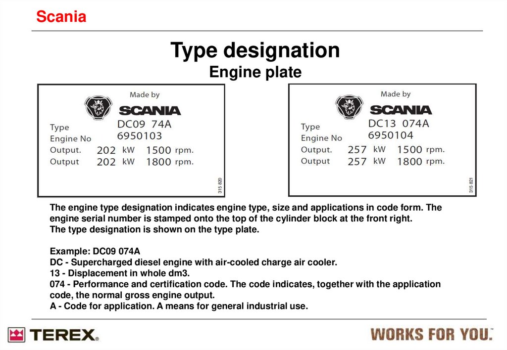
ScaniaType designation
Engine plate
The engine type designation indicates engine type, size and applications in code form. The
engine serial number is stamped onto the top of the cylinder block at the front right.
The type designation is shown on the type plate.
Example: DC09 074A
DC - Supercharged diesel engine with air-cooled charge air cooler.
13 - Displacement in whole dm3.
074 - Performance and certification code. The code indicates, together with the application
code, the normal gross engine output.
A - Code for application. A means for general industrial use.
4.
ScaniaLocation on engine
The illustrations show a normal version of a DC09
engine. The actual engine may have different
equipment.
1. Turbocharger
2. Oil cooler
3. Oil filler
4. Engine serial number on the cylinder block
5. Oil filter
6. Coolant pump
7. Draining coolant
8. Oil filter unit
9. Type designation
5.
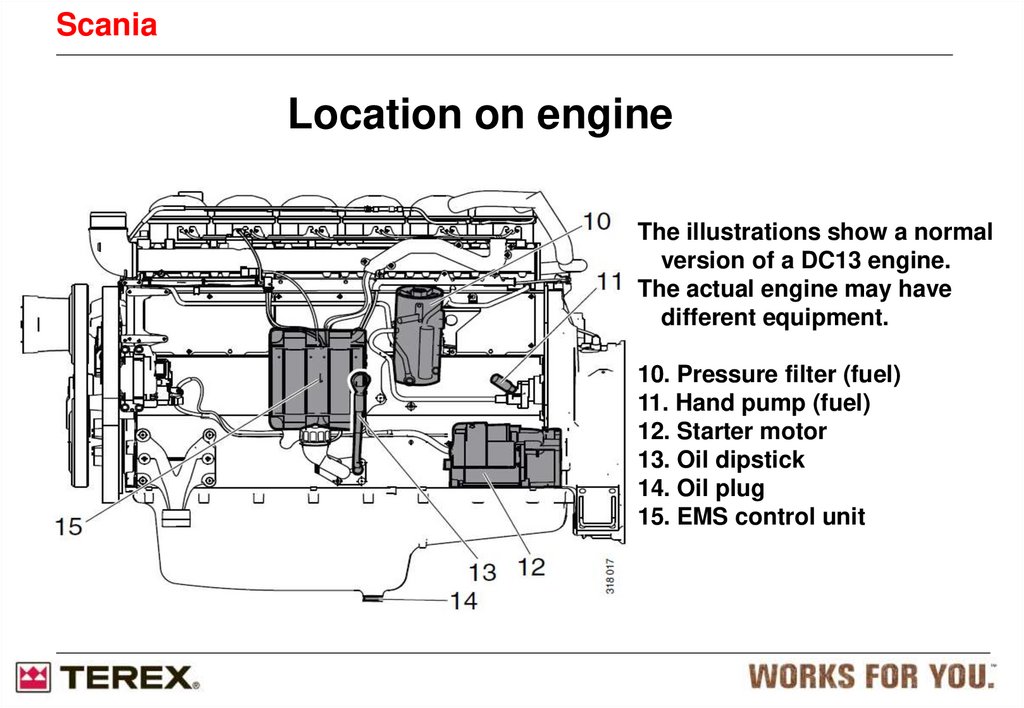
ScaniaLocation on engine
The illustrations show a normal
version of a DC13 engine.
The actual engine may have
different equipment.
10. Pressure filter (fuel)
11. Hand pump (fuel)
12. Starter motor
13. Oil dipstick
14. Oil plug
15. EMS control unit
6.
ScaniaInspection interval
Maintenance first 500 h.
• Check/Adjust valve clearance and PDE height
• Change oil and oil filter (cartridge type)
• Clean the oil centrifugal filter
7.
DailyFirst time at
First
start
Lubrication system
Inspection
interval
Checking oil level.
X
500
1000
2000
Renewing the oil filter.
X
X
X1
X
X
X1
Electrical system
X
Checking the electrolyte level in batteries
Checking state of charge.
Checking the drive belt.
Checking and adjusting the valve
Clearance and injectors
X
X
X
X
X
X
X
X
X
X
X
Checking the coolant level monitor.
Other
X
X
Cleaning the batteries.
Check for leaks.
X
X
X
Renewing the fuel filter.
1 =More often if required
X
X
Renewing the safety cartridge.
Checking fuel level.
X
X1
Cleaning or renewal of the filter element
Fuel system
Every
5 years
X
X
X
Cleaning the cooling system and
changing coolant.
Reading the vacuum indicator.
Annually
X
Checking coolant antifreeze or
corrosion protection.
Air cleaner
6000
X1
X1
X1
Cleaning the centrifugal oil cleaner.
Checking coolant level.
500
At least
X
Changing the oil.
Cooling system
Interval (hours)
X
X
X
X
8.
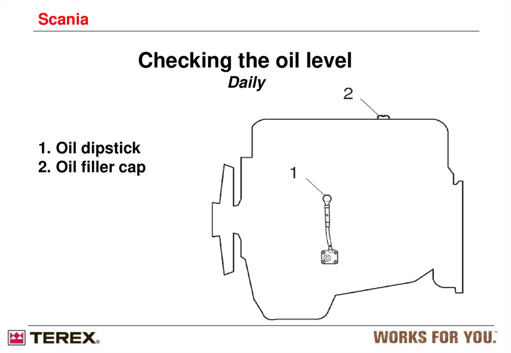
ScaniaChecking the oil level
Daily
1. Oil dipstick
2. Oil filler cap
9.
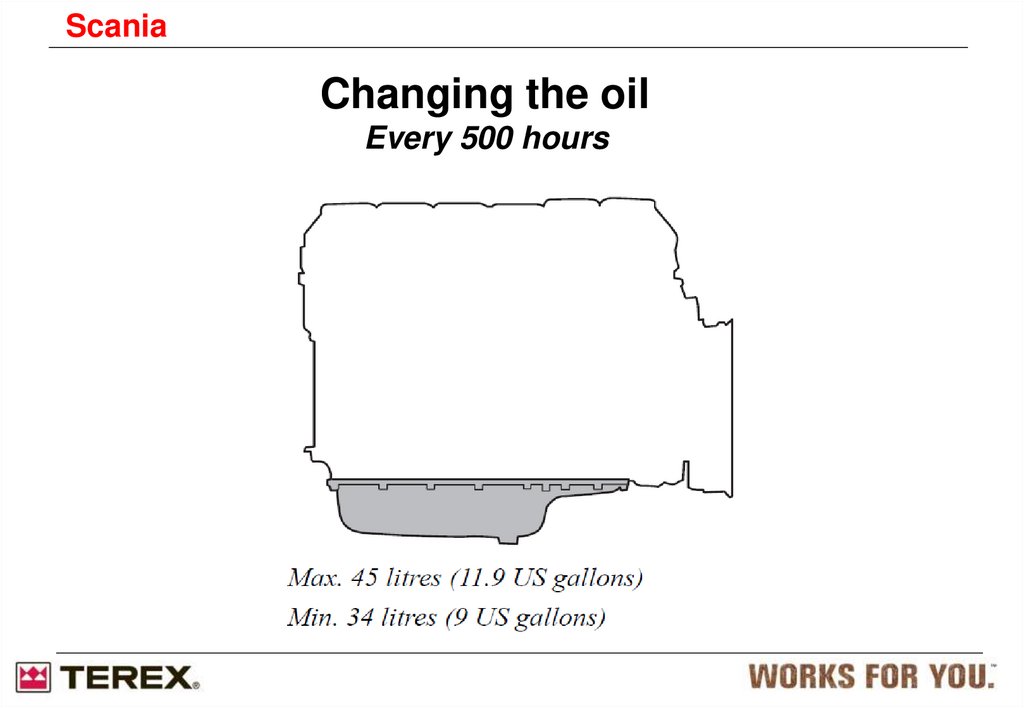
ScaniaChanging the oil
Every 500 hours
10.
ScaniaWhy SCR
Low CO2 emissions
High outputs
Response
Sulphur level in fuel
Cooling demand
Prepared for Stage 4 and Tier 4f
No particulate filter
• Regeneration not required
• Lower fuel consumption (regeneration, exhaust back
pressure)
• Reduced maintenance
11.
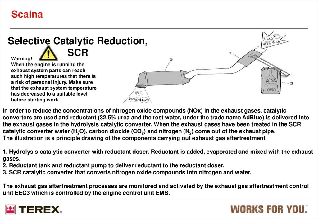
ScainaSelective Catalytic Reduction,
SCR
Warning!
When the engine is running the
exhaust system parts can reach
such high temperatures that there is
a risk of personal injury. Make sure
that the exhaust system temperature
has decreased to a suitable level
before starting work
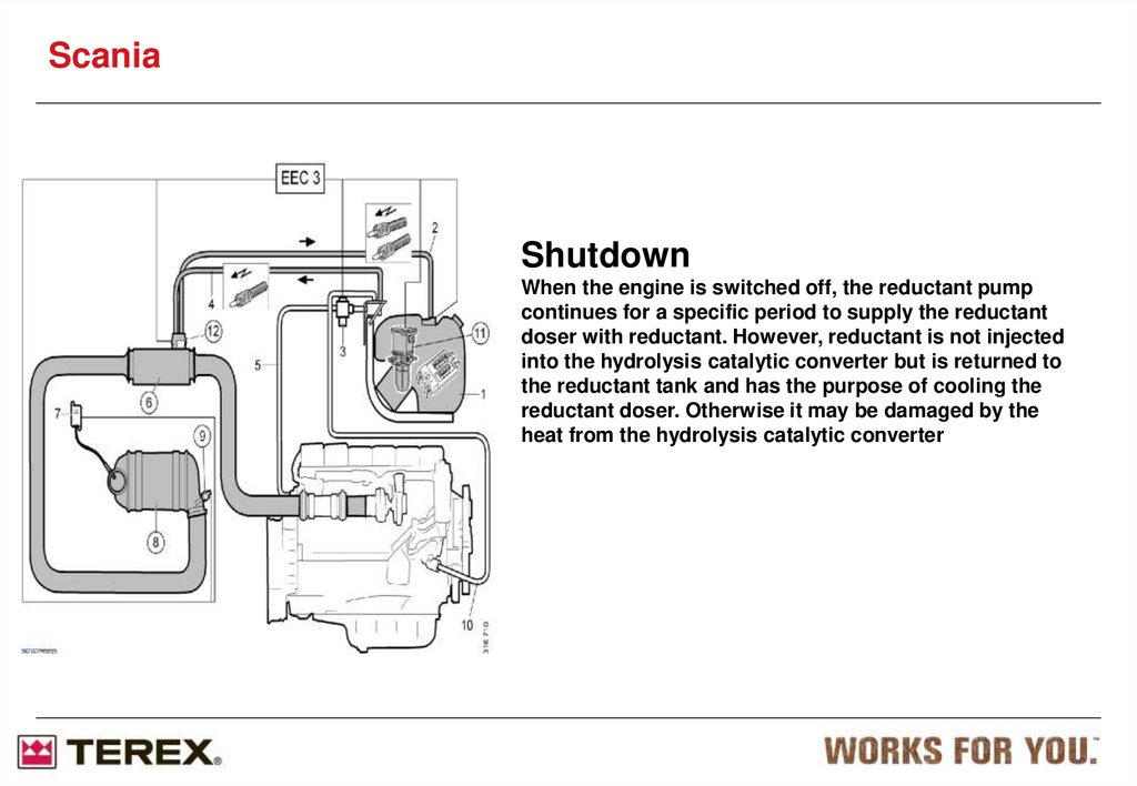
In order to reduce the concentrations of nitrogen oxide compounds (NOx) in the exhaust gases, catalytic
converters are used and reductant (32.5% urea and the rest water, under the trade name AdBlue) is delivered into
the exhaust gases in the hydrolysis catalytic converter. When the exhaust gases have been treated in the SCR
catalytic converter water (H2O), carbon dioxide (CO2) and nitrogen (N2) come out of the exhaust pipe.
The illustration is a principle drawing of the components carrying out exhaust gas aftertreatment.
1. Hydrolysis catalytic converter with reductant doser. Reductant is added, evaporated and mixed with the exhaust
gases.
2. Reductant tank and reductant pump to deliver reductant to the reductant doser.
3. SCR catalytic converter that converts nitrogen oxide compounds into nitrogen and water.
The exhaust gas aftertreatment processes are monitored and activated by the exhaust gas aftertreatment control
unit EEC3 which is controlled by the engine control unit EMS.
12. Selective Catalytic Reduction SCR
ScaniaSelective Catalytic
Reduction
SCR
Overview of the system.
The system contains a tank with pump module
a hydrolysis catalyst with dosing unit that is mounted on the catalysts
A SCR catalyst with temperature sensor and NOx sensor
The blue hoses contain the cooling water from the engine and is used for defrosting the tank unit
when risk of freezing.
The red hoses contain urea reductant and circulate to cooling the dosing unit, these are electrical
heated
13.
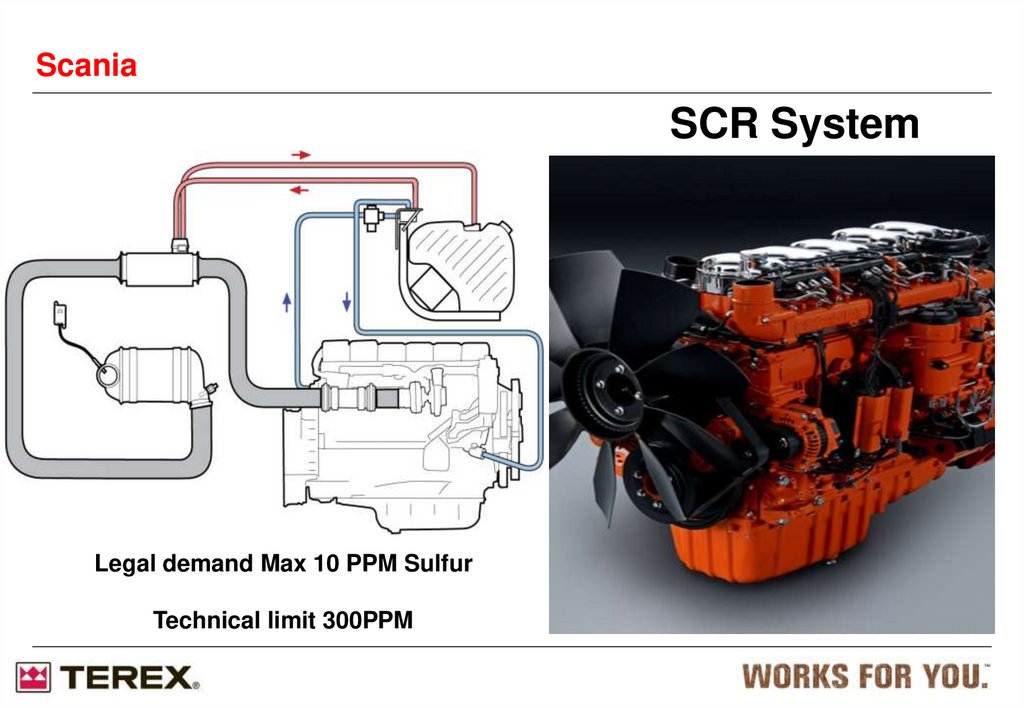
ScaniaSCR System
Legal demand Max 10 PPM Sulfur
Technical limit 300PPM
14. Exhaust Emissions
ScaniaExhaust Emissions
Diesel exhaust gases contains (legislated emissions):
• Nitrogen Oxides, NOx
• Hydro Carbons, HC
• Carbon Monoxide, CO
• Particulate matter, PM
• Of these emissions we normally talk about
NOx and PM
What is SCR?
A way to reduce NOX exhaust gases with a catalyst:
Nitrogen Oxide:
NOX + NH3* N2 + H2O
Hydro Carbons (Fuel residues): HC + O2 H2O + CO2
Carbon monoxide: CO + O2 CO2
*NH3 = ammonia compound, from
CO(NH2)2 = Urea
15. What is Urea?
ScaniaWhat is Urea?
Pure urea is in the form of white crystals
Urea dissolved in water is non toxic
Urea is corrosive to some metals such as non-alloyed steel, copper,
copper containing alloys and zinc coated steels
Commercially it’s called AdBlue, DIN70070,
Urea reductant is 32.5% weight urea, 67,5% deionised water
Freezes at -11°C
2g urea reductant → ~1g reduction of NOx
Urea reductant consumption ~5-7% of fuel
consumption for reaching stage3b/ Tier 4i emission
Urea reductant crystallizes above 100°C
16.
ScaniaLocations of sensors for EMS with S6
Location of engine speed sensors on the engine
with EMS S6.
The detail shows some of the holes in the
flywheel that are detected by the
engine speed sensors.
The EMS control unit receives signals from both engine speed sensors. If the control
unit receives a faulty signal or no signal at all from either of the engine speed sensors,
the engine torque is limited for safety reasons.
If the control unit receives a correct signal, the engine will operate normally again.
If the control unit receives a faulty signal or no signal at all from both engine speed
sensors, the engine cannot be started.
If the engine is running, it will be switched off.
The control unit senses and compares the engine speed at combustion in each
cylinder.
The control unit seeks to keep the engine speed constant by adjusting the fuel volume
individually for each cylinder.
The interval between two of the holes is greater that that between the remaining holes.
When the control unit senses that this larger interval passes the sensor, it knows that
the flywheel is
in a specific position in relation to top dead centre (TDC UP).
If the control unit detects any faults, one or more fault codes are generated.
17.
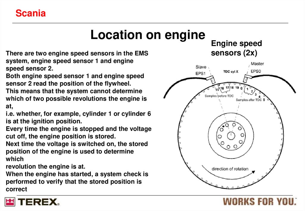
ScaniaLocation on engine
There are two engine speed sensors in the EMS
system, engine speed sensor 1 and engine
speed sensor 2.
Both engine speed sensor 1 and engine speed
sensor 2 read the position of the flywheel.
This means that the system cannot determine
which of two possible revolutions the engine is
at,
i.e. whether, for example, cylinder 1 or cylinder 6
is at the ignition position.
Every time the engine is stopped and the voltage
cut off, the engine position is stored.
Next time the voltage is switched on, the stored
position of the engine is used to determine
which
revolution the engine is at.
When the engine has started, a system check is
performed to verify that the stored position is
correct
Engine speed
sensors (2x)
18. SCR Catalysts working temp
ScaniaSCR Catalysts working temp
Exhaust temp > 200°C necessary
Good function above 250°C
Maximum function from 300°C to 500°C
If the temperature rises above 550°C-600°C the torque will
be reduced to save the catalyst.
19. Hydrolysis catalyst
ScaniaHydrolysis catalyst
Hydrolysis catalyst with dosing unit
Dosing unit cooled by urea reductant
Injection stop when DEF level reaches approx 10% in tank due to
that urea reductant is needed for cooling the dosing unit.
Make sure to install the dosing
module at correct angle 1
20. SCR catalyst with Silencer
ScaniaSCR catalyst with Silencer
Damping approx 20 dB(A)
Only for DC9 and DC13
Outlet can be rotated
Inlet
21. NOx flange
ScaniaNOx flange
NOx flange is mandatory
The flange is needed to uniform the exhaust flow for accurate
measurement of Nox gasses remaining after the catalytic
conversion.
Fitted on the SCR catalyst outlet flange.
Ensure the sensor is fitted at correct angle
22. Ambient condition sensor
ScainaAmbient condition sensor
Needed as a reference sensor to EMS
Only valid for SCR engines
Fitted between air filter and turbocharger
Measuring pressure and temperature
23.
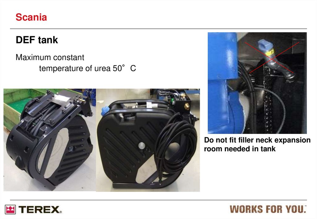
ScaniaDEF tank
Maximum constant
temperature of urea 50°C
Do not fit filler neck expansion
room needed in tank
24.
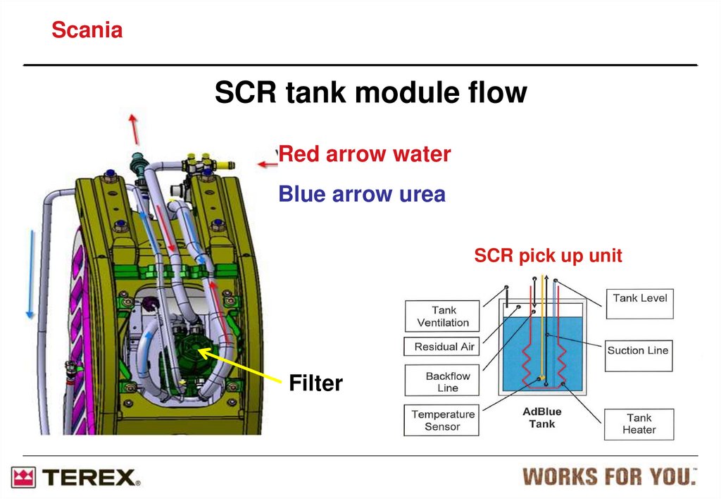
ScaniaSCR tank module flow
Red arrow water
Blue arrow urea
SCR pick up unit
Filter
25.
ScaniaFitting of the NOx control unit on exhaust cradle
Electrical cable length between sensor and control unit
600mm
26.
ScaniaWhen working with the SCR-system
Important
Make sure that you always clean the area when
working on the SCR system to prevent any spilt
reductant from drying and forming crystals which
may get into the system.
Always fit new O-rings and clean thoroughly so
that the sealing surface is clean and free from
crystals.
27.
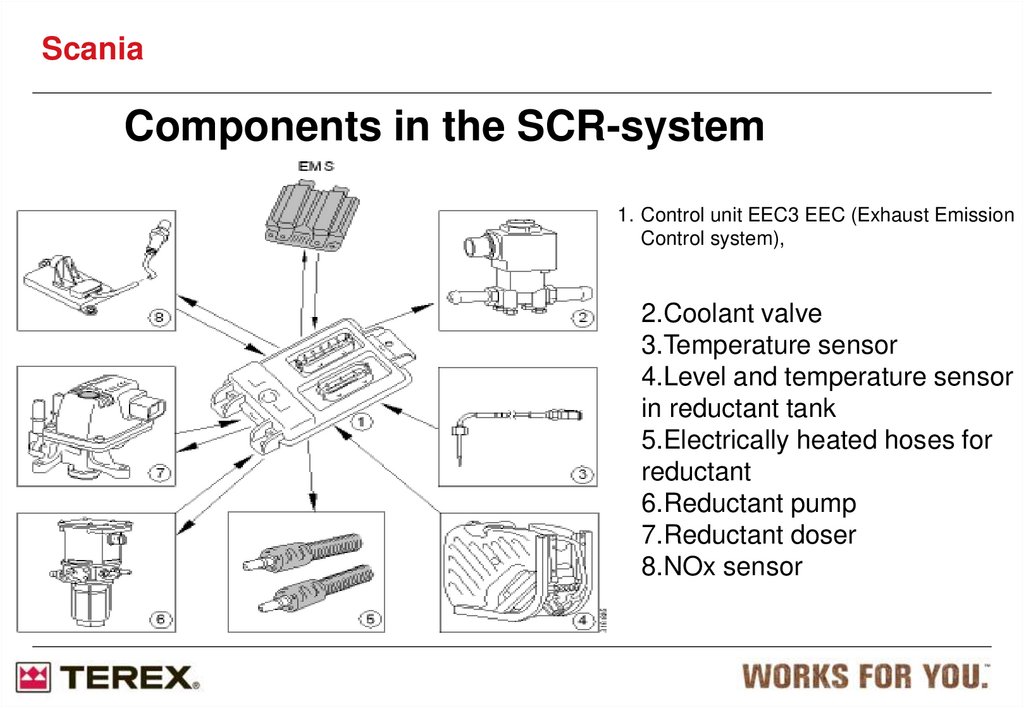
ScaniaComponents in the SCR-system
1. Control unit EEC3 EEC (Exhaust Emission
Control system),
2.Coolant valve
3.Temperature sensor
4.Level and temperature sensor
in reductant tank
5.Electrically heated hoses for
reductant
6.Reductant pump
7.Reductant doser
8.NOx sensor
28.
ScaniaControl unit EEC3 (E67)
The EEC3 control unit retrieves data from the
system's sensors and components.
EEC3 communicates with the engine control
unit EMS. EMS decides on what measures are
to be executed, e.g. what quantity of reductant
is to be metered to the exhaust gases, and
notifies EEC3.
The EEC3 control unit is independently
responsible for the functions which supply
reductant to the exhaust gases. The EEC3
control unit is located on the reductant tank
bracket underneath the reductant tank.
29.
ScaniaNOx sensor (T115)
NOx sensor (T115)
There is a NOx sensor in the system.
It is used to measure the content of
nitrogen oxide compounds in the exhaust
gases after exhaust gas aftertreatment.
This sensor reports to EEC3, which
notifies EMS. The sensor is electrically
heated by EEC3.
The NOx sensor is located on the SCR
catalytic converter's exhaust outlet.
30.
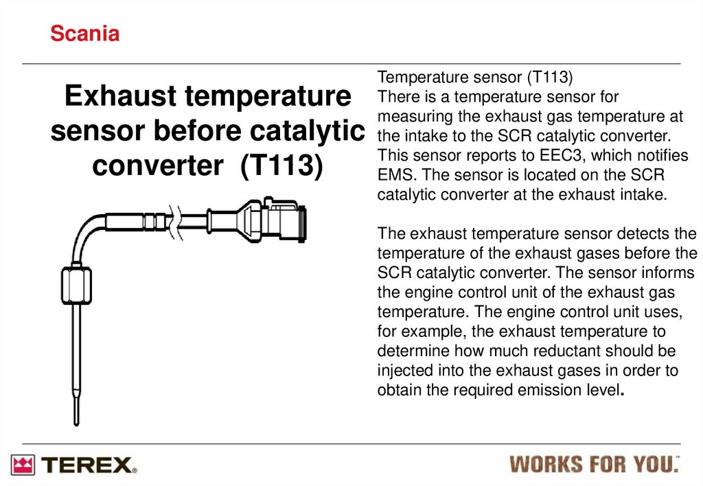
ScaniaExhaust temperature
sensor before catalytic
converter (T113)
Temperature sensor (T113)
There is a temperature sensor for
measuring the exhaust gas temperature at
the intake to the SCR catalytic converter.
This sensor reports to EEC3, which notifies
EMS. The sensor is located on the SCR
catalytic converter at the exhaust intake.
The exhaust temperature sensor detects the
temperature of the exhaust gases before the
SCR catalytic converter. The sensor informs
the engine control unit of the exhaust gas
temperature. The engine control unit uses,
for example, the exhaust temperature to
determine how much reductant should be
injected into the exhaust gases in order to
obtain the required emission level.
31.
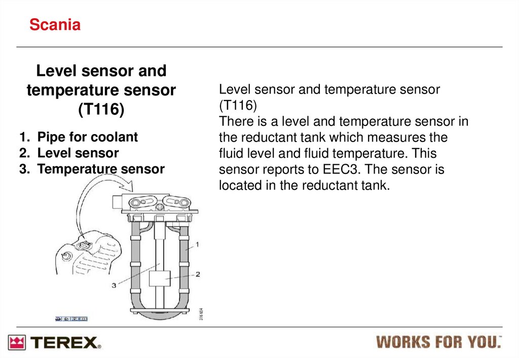
ScaniaLevel sensor and
temperature sensor
(T116)
1. Pipe for coolant
2. Level sensor
3. Temperature sensor
Level sensor and temperature sensor
(T116)
There is a level and temperature sensor in
the reductant tank which measures the
fluid level and fluid temperature. This
sensor reports to EEC3. The sensor is
located in the reductant tank.
32.
ScaniaReductant pump (V183)
Reductant pump (V183)
To achieve the right reductant
pressure prior to metering in the
exhaust system, there is an
electrically operated reductant
pump with variable speed control
in the system which is monitored
and activated by EEC3. The
reductant pump reports pump
speed to EEC3. The reductant
pump is heated by the engine's
coolant at low outdoor
temperatures. The reductant
pump is located on the reductant
tank bracket underneath the
reductant tank
33.
ScaniaReductant pump
(V183)
1.Pump unit
2.Valve block
3.Reductant filter
4.Cover
5.Connections for coolant
6.Ventilation
7.Internal hexagon bolt
8.Connection for electrical connector
9.Connections for reductant
10.Electric motor for diaphragm pump
To ensure that the correct quantity of reductant is
metered to the exhaust gases, there is an
electrically operated reductant doser in the system
which is monitored and activated by EEC3. The
reductant doser reports the pressure and
temperature of the reductant to EEC3. The
reductant doser is electrically heated and located
on the hydrolysis catalytic converter.
The reductant pump sucks reductant from the
reductant tank, filters and builds up pressure for
the reductant which is then fed to the reductant
doser.
The reductant pump is an electrically driven
diaphragm pump with a filter for cleaning the
reductant. The reductant pump is heated using the
engine's coolant at low outdoor temperatures in
order to thaw frozen reductant or prevent it
freezing.
34.
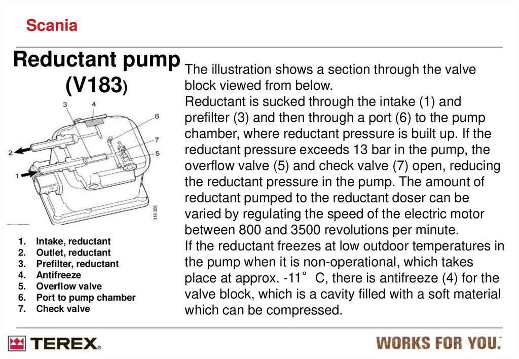
ScaniaReductant pump The illustration shows a section through the valve
block viewed from below.
(V183)
1.
2.
3.
4.
5.
6.
7.
Intake, reductant
Outlet, reductant
Prefilter, reductant
Antifreeze
Overflow valve
Port to pump chamber
Check valve
Reductant is sucked through the intake (1) and
prefilter (3) and then through a port (6) to the pump
chamber, where reductant pressure is built up. If the
reductant pressure exceeds 13 bar in the pump, the
overflow valve (5) and check valve (7) open, reducing
the reductant pressure in the pump. The amount of
reductant pumped to the reductant doser can be
varied by regulating the speed of the electric motor
between 800 and 3500 revolutions per minute.
If the reductant freezes at low outdoor temperatures in
the pump when it is non-operational, which takes
place at approx. -11°C, there is antifreeze (4) for the
valve block, which is a cavity filled with a soft material
which can be compressed.
35.
ScaniaReductant pump
(V183)
1.
2.
3.
4.
5.
6.
7.
8.
9.
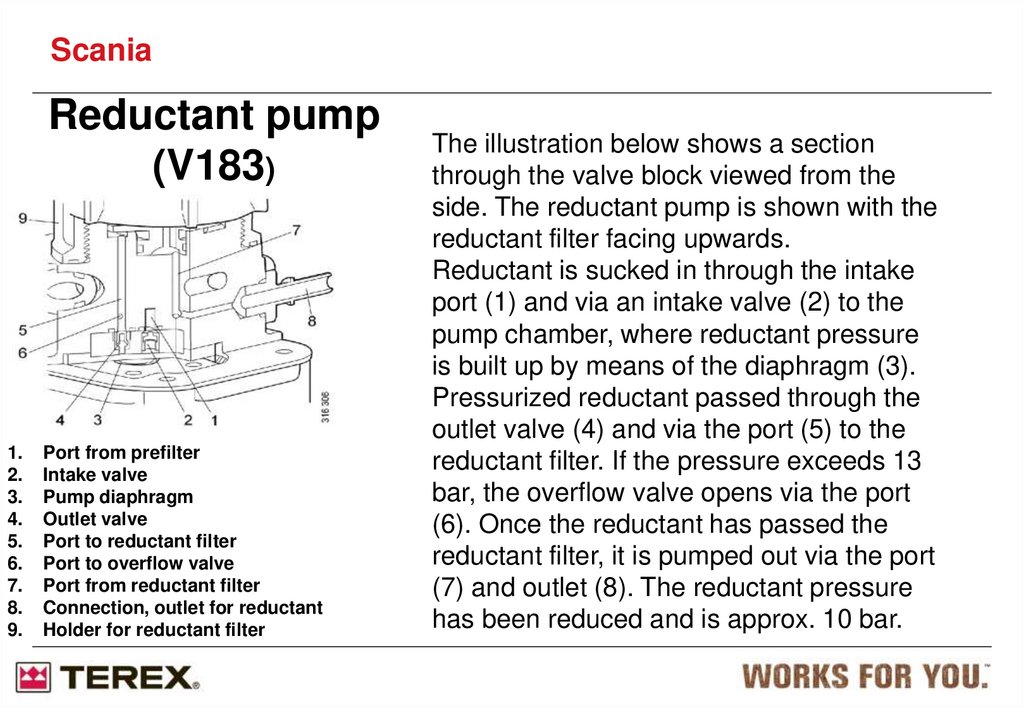
Port from prefilter
Intake valve
Pump diaphragm
Outlet valve
Port to reductant filter
Port to overflow valve
Port from reductant filter
Connection, outlet for reductant
Holder for reductant filter
The illustration below shows a section
through the valve block viewed from the
side. The reductant pump is shown with the
reductant filter facing upwards.
Reductant is sucked in through the intake
port (1) and via an intake valve (2) to the
pump chamber, where reductant pressure
is built up by means of the diaphragm (3).
Pressurized reductant passed through the
outlet valve (4) and via the port (5) to the
reductant filter. If the pressure exceeds 13
bar, the overflow valve opens via the port
(6). Once the reductant has passed the
reductant filter, it is pumped out via the port
(7) and outlet (8). The reductant pressure
has been reduced and is approx. 10 bar.
36.
ScaniaReductant
doser (V182)
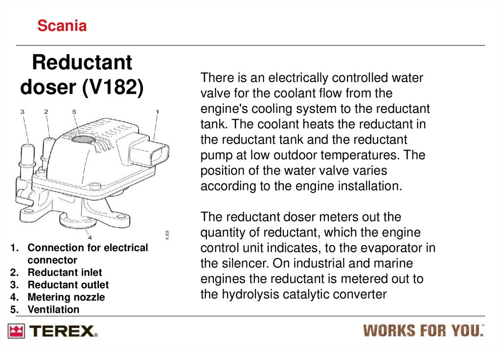
1. Connection for electrical
connector
2. Reductant inlet
3. Reductant outlet
4. Metering nozzle
5. Ventilation
There is an electrically controlled water
valve for the coolant flow from the
engine's cooling system to the reductant
tank. The coolant heats the reductant in
the reductant tank and the reductant
pump at low outdoor temperatures. The
position of the water valve varies
according to the engine installation.
The reductant doser meters out the
quantity of reductant, which the engine
control unit indicates, to the evaporator in
the silencer. On industrial and marine
engines the reductant is metered out to
the hydrolysis catalytic converter
37.
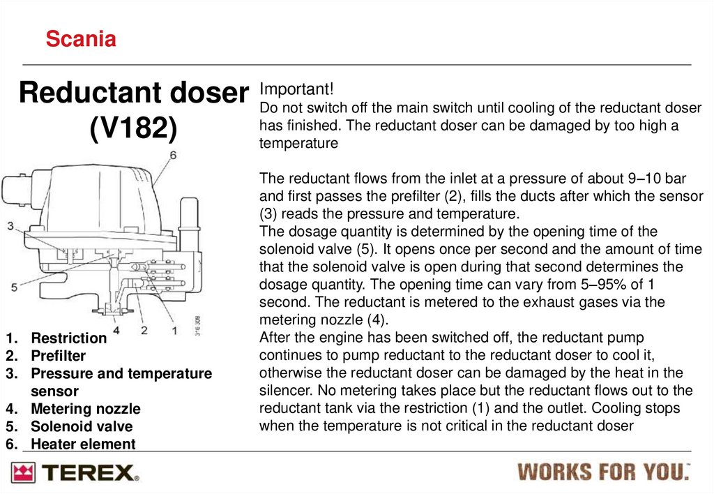
ScaniaReductant doser Important!
Do not switch off the main switch until cooling of the reductant doser
has finished. The reductant doser can be damaged by too high a
(V182)
temperature
1. Restriction
2. Prefilter
3. Pressure and temperature
sensor
4. Metering nozzle
5. Solenoid valve
6. Heater element
The reductant flows from the inlet at a pressure of about 9–10 bar
and first passes the prefilter (2), fills the ducts after which the sensor
(3) reads the pressure and temperature.
The dosage quantity is determined by the opening time of the
solenoid valve (5). It opens once per second and the amount of time
that the solenoid valve is open during that second determines the
dosage quantity. The opening time can vary from 5–95% of 1
second. The reductant is metered to the exhaust gases via the
metering nozzle (4).
After the engine has been switched off, the reductant pump
continues to pump reductant to the reductant doser to cool it,
otherwise the reductant doser can be damaged by the heat in the
silencer. No metering takes place but the reductant flows out to the
reductant tank via the restriction (1) and the outlet. Cooling stops
when the temperature is not critical in the reductant doser
38.
ScaniaReductant doser
(V182)
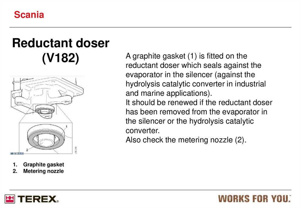
1.
2.
Graphite gasket
Metering nozzle
A graphite gasket (1) is fitted on the
reductant doser which seals against the
evaporator in the silencer (against the
hydrolysis catalytic converter in industrial
and marine applications).
It should be renewed if the reductant doser
has been removed from the evaporator in
the silencer or the hydrolysis catalytic
converter.
Also check the metering nozzle (2).
39.
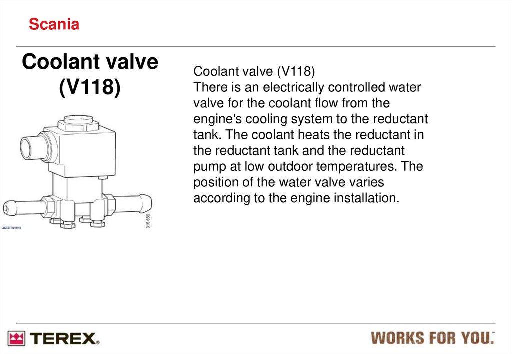
ScaniaCoolant valve
(V118)
Coolant valve (V118)
There is an electrically controlled water
valve for the coolant flow from the
engine's cooling system to the reductant
tank. The coolant heats the reductant in
the reductant tank and the reductant
pump at low outdoor temperatures. The
position of the water valve varies
according to the engine installation.
40.
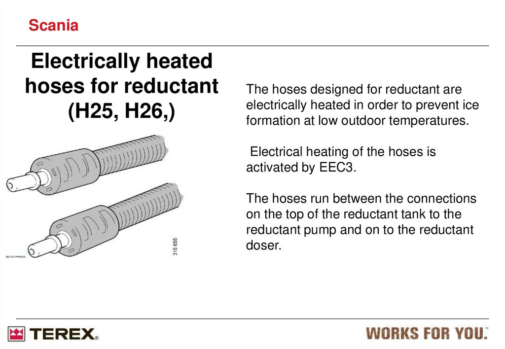
ScaniaElectrically heated
hoses for reductant
(H25, H26,)
The hoses designed for reductant are
electrically heated in order to prevent ice
formation at low outdoor temperatures.
Electrical heating of the hoses is
activated by EEC3.
The hoses run between the connections
on the top of the reductant tank to the
reductant pump and on to the reductant
doser.
41.
ScaniaSystem overview for
electrics
The locations of components vary
depending on the engine version and
installation. For information on detailed
locations,
see the overview for the component in
question.
1.Control unit EEC3
2.NOx sensor
3.Temperature sensor
4.Level and temperature sensor
5.Reductant pump
6.Reductant doser
7.Coolant valve
8.Electrically heated hoses for reductant
42.
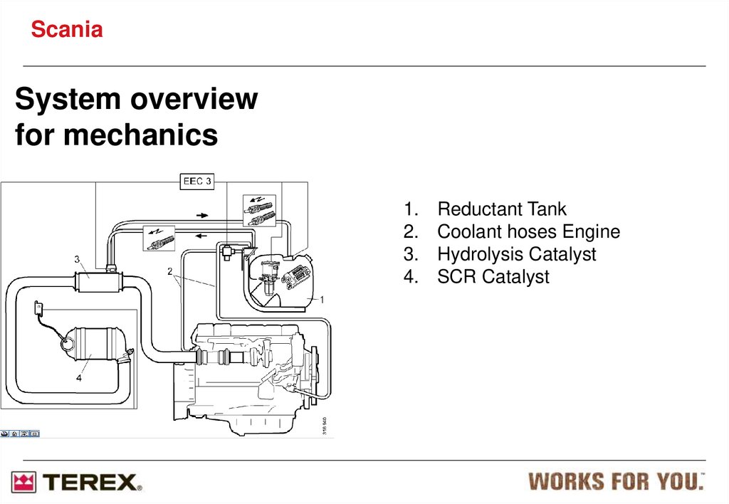
ScaniaSystem overview
for mechanics
1.
2.
3.
4.
Reductant Tank
Coolant hoses Engine
Hydrolysis Catalyst
SCR Catalyst
43.
ScaniaReductant filter
The illustration shows the reductant filter
(1) facing upwards.
The reductant filter must be renewed
according to the specified inspection
interval.
If the reductant freezes at low outdoor
temperatures when the reductant pump is
non-operational, which takes place at
approx. -11°C, there is antifreeze (2) for
the valve block, which is a cavity filled
with a soft material which can be
compressed.
1. Reductant filter
2. Antifreeze
44.
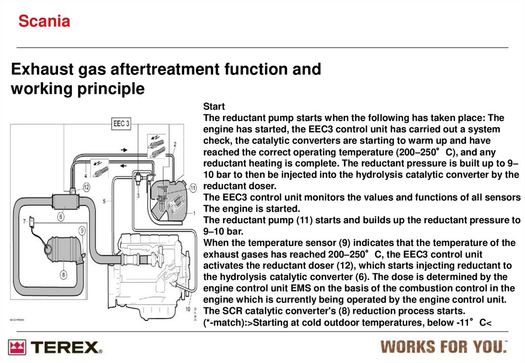
ScaniaExhaust gas aftertreatment function and
working principle
Start
The reductant pump starts when the following has taken place: The
engine has started, the EEC3 control unit has carried out a system
check, the catalytic converters are starting to warm up and have
reached the correct operating temperature (200–250°C), and any
reductant heating is complete. The reductant pressure is built up to 9–
10 bar to then be injected into the hydrolysis catalytic converter by the
reductant doser.
The EEC3 control unit monitors the values and functions of all sensors
The engine is started.
The reductant pump (11) starts and builds up the reductant pressure to
9–10 bar.
When the temperature sensor (9) indicates that the temperature of the
exhaust gases has reached 200–250°C, the EEC3 control unit
activates the reductant doser (12), which starts injecting reductant to
the hydrolysis catalytic converter (6). The dose is determined by the
engine control unit EMS on the basis of the combustion control in the
engine which is currently being operated by the engine control unit.
The SCR catalytic converter's (8) reduction process starts.
(*-match):>Starting at cold outdoor temperatures, below -11°C<
45.
ScaniaOperation and reductant metering
The exhaust gases are treated in a number of steps before being released via the tailpipe. These steps are based
on the combustion control mode of the engine control unit. First, the exhaust gases are mixed with reductant
when they pass the hydrolysis catalytic converter (6).
The process of hydrocarbon reduction begins in the hydrolysis catalytic converter (6) and ends in the SCR
catalytic converter (8).
Once the exhaust gases have passed the hydrolysis catalytic converter (6), the exhaust gas temperature is
measured using the temperature sensor (9). The value is read off by the EEC3 control unit and transmitted to the
engine control unit. The values from the temperature sensor (9) are used by the engine control unit to control
the exhaust gas temperature, which should be between 200 and 250°C. This can be done with the exhaust
brake, if fitted, the injection system XPI or a combination of the two.
The exhaust gases then pass through the SCR catalytic converter (8) where most reduction of hydrocarbons
takes place by means of reductant injected in previously. NOx is converted into water, carbon dioxide and
ammonia.
The volume of reductant mixed with the exhaust gases in the hydrolysis catalytic converter (6) is determined by
the engine control unit, activated by the EEC3 control unit and carried out by the reductant doser (12). The dose
is determined by the engine control unit on the basis of the values from the NOx sensor (7), temperature sensor
(9) and the combustion control mode of the engine control unit.
The EEC3 control unit activates injection of reductant to the hydrolysis catalytic converter (6) from the reductant
tank (1) by means of the reductant pump (11) and the reductant doser (12).
46.
ScaniaShutdown
When the engine is switched off, the reductant pump
continues for a specific period to supply the reductant
doser with reductant. However, reductant is not injected
into the hydrolysis catalytic converter but is returned to
the reductant tank and has the purpose of cooling the
reductant doser. Otherwise it may be damaged by the
heat from the hydrolysis catalytic converter
47.
ScaniaXPI Fuel System
XPI = Extra high Pressure Injection
Scania XPI is a new generation
Common Rail (CR) system
Developed by Scania in cooperation
with Cummins
Average pressure 1800 bar
Max pressure 2400 bar
48. Historical overwiew
ScaniaHistorical overwiew
PDE
HPI
XPI
Unit injector systems = high pressure
generated in each injector
Common rail system = separate high
pressure pump
Injection pressure is a function of engine
speed and injected fuel amount
Injection pressure independent of
speed and injected fuel amount
49. Benefits from Scania XPI
ScaniaBenefits from Scania XPI
Injection timing or duration independent of camshaft position
Higher average injection pressure compared to unit injector and
inline pump systems
Injection pressure can be regulated independently of engine
speed and amount of fuel injected
Simplified valve train since the pushrods for unit injectors are no
longer needed
Multiple injections are possible
50.
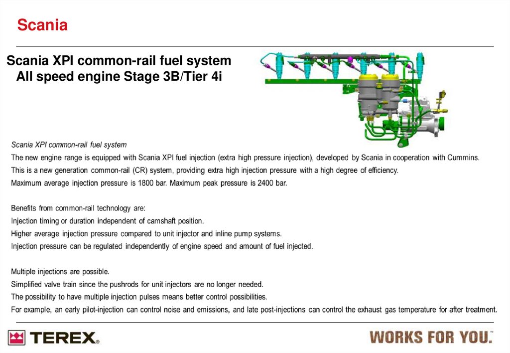
ScaniaScania XPI common-rail fuel system
All speed engine Stage 3B/Tier 4i
51. XPI System Overview
ScaniaXPI System Overview
Injector w/ Electronically
Controlled Pilot Valve
Accumulator
(Only 1 Shown)
Mechanical Dump Valve
High Pressure
Connectors
Rail Pressure Sensor
High Pressure Line
High Pressure
Pump
Fuel Filters
Inlet Metering Valve
Low Pressure Pump
52.
ScaniaFuel Connections XPI
53. Scania XPI
Fuel RailMechaniccal Dump Valve
High Pressure Connectors
Pressure Sensor
High Pressure
Line
Injector
Bleed
Hand Pump
Fuel Manifold
Inlet Metering Valve
Fuel Heater
350W 5-24 deg
Fuel Filter 1
10 microns
Fuel Filter 2
3 microns
Low Pressure Pump
High Pressure Pump
54.
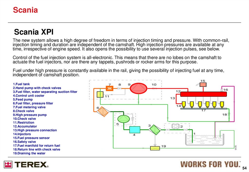
ScaniaScania XPI
The new system allows a high degree of freedom in terms of injection timing and pressure. With common-rail,
injection timing and duration are independent of the camshaft. High injection pressures are available at any
time, irrespective of engine speed. It also opens the possibility to use several injection pulses, see below.
Control of the fuel injection system is all-electronic. This means that there are no lobes on the camshaft to
actuate the fuel injectors, nor are there any tappets, pushrods or rocker arms for this purpose.
Fuel under high pressure is constantly available in the rail, giving the possibility of injecting fuel at any time,
independent of camshaft position.
1.Fuel tank
2.Hand pump with check valves
3.Fuel filter, water separating suction filter
4.Control unit cooler
5.Feed pump
6.Fuel filter, pressure filter
7.Fuel metering valve
8.Check valve
9.High pressure pump
10.Check valve
11.Restriction
12.Accumulator
13.High pressure connection
14.Injectors
15.Fuel pressure sensor
16.Safety valve
17.Fuel manifold for return fuel
18.Return line with check valve
19.Draining the water
54
55.
ScaniaScania XPI
Working principle of Scania XPI
Fuel is sucked from the tank by the low-pressure pump via a prefilter with a water separator via the
cooling circuit for the engine management system to the main fuel filters. Water in the fuel is
automatically drained back to the tank via a venturi device.
The low-pressure pump supplies fuel via the inlet metering valve to the high-pressure fuel pump. The
pumps, which are integrated into one unit together with the fuel metering valve, are driven by the timing
gears of the engine.
The high-pressure pump supplies fuel under operating pressure to the rail, i.e. the accumulator running
the length of the engine on the cool side.
The operating pressure is regulated by the amount of fuel admitted by the inlet metering valve, ranging
from an idling pressure of around 500 bar to a peak pressure of 2400 bar. The average working
pressure is around 1800 bar.
The inlet metering valve is controlled electronically by the engine management system via a closed loop
from a pressure sensor in the rail. A mechanical dump valve on the rail prevents excess pressure buildup by sending fuel back to the tank via the return rail.
The fuel injector for each cylinder is constantly fed with high-pressure fuel from the rail. Injection pulses
are controlled electronically via a servo valve in the injector. The injector remains open as long as
current is supplied from the ECU.
The amount of fuel injected depends on the opening time and the pressure in the rail. The starting time
of the pulse determines the start of injection.
Fuel is injected into the combustion chamber through the injector nozzle.
55
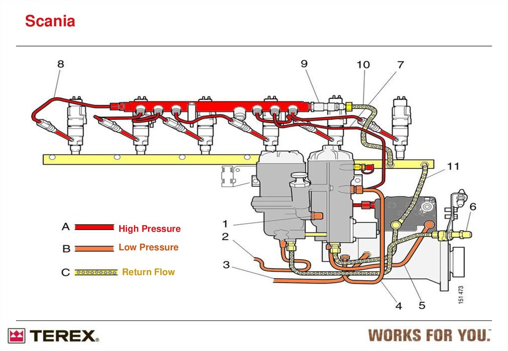
56.
ScaniaHigh Pressure
Low Pressure
Return Flow
57.
ScaniaThis is how Venturi
device works
Inlet from
low pressure
pump
A small quantity of the
pressurized fuel from low
pressure pump (dark blue)
goes into Venturi housing;
due to Venturi effect a
suction force is created and
fuel mixed with water (light
blue) is drawn through a
pipe between the fuel filter
housings and push it into
the normal return line to the
fuel tank.
Return to
the fuel tank
Venturi
housing
Outlet to HPP
Inlet from return
manifold
58.
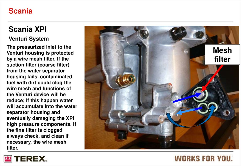
ScaniaScania XPI
Venturi System
The pressurized inlet to the
Venturi housing is protected
by a wire mesh filter. If the
suction filter (coarse filter)
from the water separator
housing fails, contaminated
fuel with dirt could clog the
wire mesh and functions of
the Venturi device will be
reduce; if this happen water
will accumulate into the water
separator housing and
eventually damaging the XPI
high pressure components. If
the fine filter is clogged
always check, and clean if
necessary, the wire mesh
filter.
Mesh
filter
59. XPI HPP, Cut away view
ScaniaXPI HPP, Cut away view
Inlet fuel from IMV
IMV
Inlet metering
valve
Variable displacement
pump. Pistons stroke
only as big as
necessary
Barrel
LPP
Low pressure pump
Internal pressure
relief valve in feed
pump 9-13 bar
Camshaft
60. XPI HPP Head Assembly
60Scania
XPI HPP Head
Assembly
Inlet fuel from IMV
Outlet fuel
to
accumulator
Outlet
checkvalve
Ceramic plunger
has a 3 micron
clearance.
Inlet
checkvalve
Drain drilling
Barrel
Seal washer
Drain channel
CeramicPlunger
Spring
2-bump
camshaft
Plunger lift
roller
61. XPI Barrel Design
ScaniaXPI Barrel Design
o-ring
seal washer
“1-pce” bbl
(externally threaded)
62.
ScaniaRail Pressure Sensor
General Description
Pressure range of 0-2850bar
+5Vdc power supply
0.5-4.5V output
-40 to 125ºC overall operating range
63.
ScaniaRail Pressure Sensor
General Description
Pressure range of 0-2850bar
+5Vdc power supply
0.5-4.5V output
-40 to 125ºC overall operating range
19
64.
ScaniaAccumulator
Fuel pressure sensor
connection
Accumulator chamber
High pressure line
connections
Mechanical dump valve
(safety valve)
The common rail system uses a type of accumulation chamber called a rail to store pressurized fuel, and
injectors that contain electronically controlled solenoid valves to inject the pressurized fuel into the
cylinders. When the fuel pressure becomes higher than normal a mechanical dump valve (also named
safety valve) dumps the overpressure to return manifold.
65.
ScaniaBody
Safety Relief Valve
Spring
Retainer
Spring
O-Ring
2nd Stage
Plunger
1snd Stage Plunger
Shim
Spring = 3000
Opening Pressure:
3100 bars
Limp Home Pressure:
1000 ±300 bars
FUEL
Bleed down orifice
1000
Dual-Stage Safety valve:
Cone-on-Cone on 1st Stage
Cone-on-Cone on 2nd Stage
66. XPI Injector
ScaniaXPI Injector
Injector Scania XPI
Function
Phase 1, no power to the solenoid valve in the injector
Phase 2, power to the solenoid valve in the injector
Function
There is one injector for each cylinder. The injector is controlled electrically by the engine control unit.
The injector operates in two phases. One phase is when no power is supplied to the injector and it is closed.
The other phase is when power is supplied to the injector and it is open.
The injector consists of a piston, nozzle needle, spring and an electromagnetically controlled fuel valve.
The fuel enters the injector via the high pressure connection. The injector is continuously pressurised to a
maximum of 2400 bar. When the solenoid valve is supplied with power and opens, fuel is injected into the
cylinder.
Injection timing and the amount of fuel to be injected is determined by the engine control unit. Injection duration
and the fuel pressure in the accumulator determine the amount of fuel which is injected into the cylinder.
Stator Spring
Spring Retainer
Stator Spacer
Spring Washer
Overtravel
Spring
Ball Retainer
Ball
Stroke Shim
Plunger Seal
Floating Sleeve
Phase 1, no power to the solenoid valve in the injector
No power is supplied to the injector solenoid valve and the injector is closed. There is a fuel pressure of
between 350 and a maximum of 2400 bar in the injector.
Spring
Plunger
Nozzle
Phase 2, power to the solenoid valve in the injector
Power is supplied to the injector solenoid valve which then opens, so that the fuel flows up into the valve part.
The pressure difference which arises in the injector means that the piston is drawn upwards and fuel is injected
into the cylinders.
When power is again switched off to the solenoid valve, the fuel pressure in the injector pushes the piston
downwards and closes the injector
Nozzle Retainer
67. Phase 1 & 2 of Injection
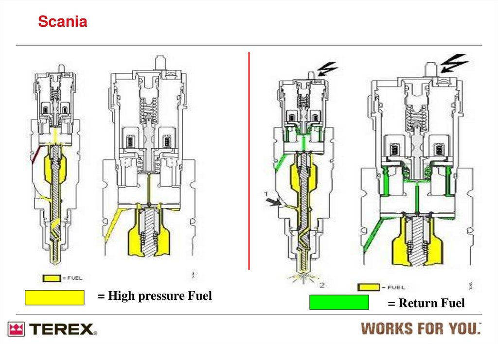
ScaniaPhase 1 & 2 of Injection
68.
Scania= High pressure Fuel
= Return Fuel
69. Injectors: Individual adjustment code
ScaniaInjectors: Individual adjustment code
Each injector has an individual adjustment code. This code has to be
entered into the ECU each time an injector is exchanged.This operation
has to be performed with SDP 3.
The purpose of the individual adjustment code is to reduce variation
between injectors. The result is an engine that runs smoother and
delivers the correct power output.
After changing the injectors you need to, CLEAR fuel data
70.
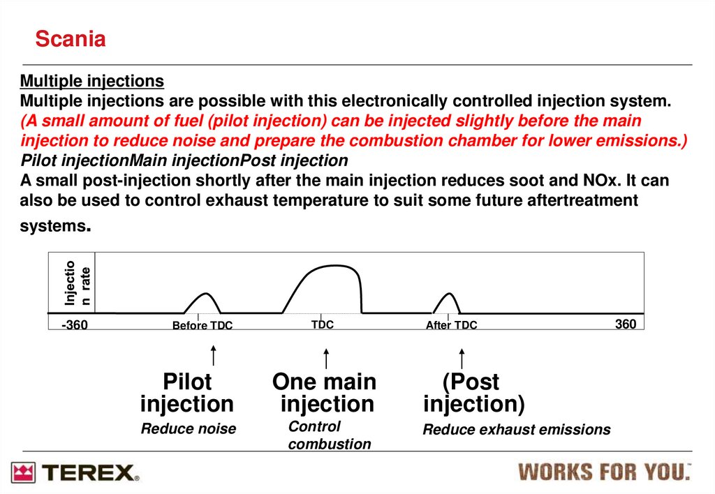
ScaniaMultiple injections
Multiple injections are possible with this electronically controlled injection system.
(A small amount of fuel (pilot injection) can be injected slightly before the main
injection to reduce noise and prepare the combustion chamber for lower emissions.)
Pilot injectionMain injectionPost injection
A small post-injection shortly after the main injection reduces soot and NOx. It can
also be used to control exhaust temperature to suit some future aftertreatment
systems.
-360
Before TDC
TDC
Pilot
injection
One main
injection
Reduce noise
Control
combustion
After TDC
(Post
injection)
Reduce exhaust emissions
360
71.
ScaniaInjector assembly
Injector clamp
High Pressure
Connector
High Pressure
Line
72. Cleanliness requirement
ScaniaCleanliness requirement
Many internal parts in the system are sensitive to dirt and water droplets. This is due to that the
dimensions are very small, the surface finish requirements are high, and the pressures are
extremely high. Examples of sensitive parts are:
• Pilot valve (injector)
• Needle seal with floating sleeve (injector)
• Plungers / barrels (HPP)
• Inlet and outlet checkvalves (HPP)
This means that cleanliness is more important than ever when working on fuel system
components.
73.
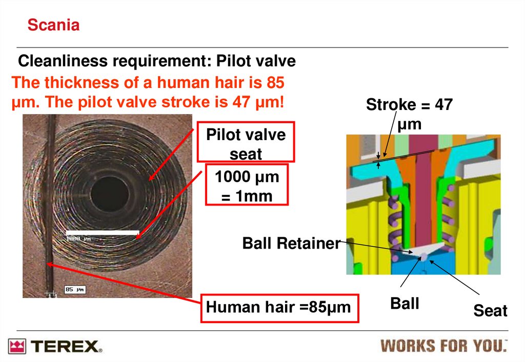
ScaniaCleanliness requirement: Pilot valve
The thickness of a human hair is 85
μm. The pilot valve stroke is 47 μm!
Pilot valve
seat
1000 μm
= 1mm
Stroke = 47
μm
Ball Retainer
Human hair =85μm
Ball
Seat
74. Cleanliness requirements: Pilot valve ball
ScaniaCleanliness requirements: Pilot valve ball
The size of the
ball is around 1
mm. This ball is
exposed to a
pressure of
2200 bar. Debris
between ball
and seat =
leakage and
uncontrolled
fueling
75.
ScaniaCleanliness requirement: General
Do not use compressed air for cleaning purposes.
Use only non-fluffy cleaning cloths on the fuel system
When removing and fitting components, do not use materials like
fluffy cloths, cardboard or wood.
Use undamaged tools (not with split chrome surfaces)
Do not remove parts from their original enclosure until immediately
before assembly.
If you need to send the part somewhere: use a new plastic bag and
seal it properly. If possible, use the original packing of the new part.
76. Service: Safety
ScaniaService: Safety
Due to the high fuel pressure, leakage can cause jets of fuel that penetrates
through the skin!
Always consider the high pressure part of the system (accumulator and high
pressure lines) as pressurized. The pressure could be as high as 2400 bar.
This applies also to an engine that is not running!
Before working on any of the fuel system components: De-pressurize the
system by use of SDP3 and then untightening the cylinder high pressure
line nut at the accumulator of the cylinder you are going to work on. Cover
the nut with a cloth during the operation. Use safety glasses and gloves.
Avoid standing closer than 1 m to a running engine. Fuel jets will diverge within
this distance from the source and become less harmful.
77.
ScaniaS8 Engine Management System (EMS) The S8 EMS is introduced with
1. T21, charge air temperature sensor
2. T22, charge air pressure sensor
3. T33, coolant temperature sensor
4. T5, oil pressure sensor
5. T74, T75, engine speed sensors
6. T110, oil level sensor, available as an option
7. T111, fuel pressure sensor
8. V141-V148, XPI injectors
9. V120, fuel inlet metering valve
10. T125, exhaust back pressure sensor
11. T120, turbo speed sensor
12. M30, electric motor for adjustable turbocharger
13. T126, intake air temperature and flow sensor
14. T124, position sensor for the EGR valve
15. V107, valve block with a proportional valve for
the EGR valve and exhaust brake
16. T123, rotation speed sensor and fan solenoid
valve
17. M1, starter motor
18. P3, alternator
19. V2, coupling coil for AC compressor
improved memory addressing,
and is prepared future demands.
Input from gearbox temperature
sensor, additional NOx sensor
etc
New architecture for calculations
in EMS.
78.
ScaniaTroubleshooting: Tools
To apply the
methods described
here you need the
pressure sensor +
amplifier included in
Scania pressure
measurment kit (P/N
99362) or another
suitable sensor. You
also need a
multimeter.
Note: Pressure is
displayed in Mpa.
0,1 MPa = 1 bar
Pressure sensor +
amplifier
Multimeter
79.
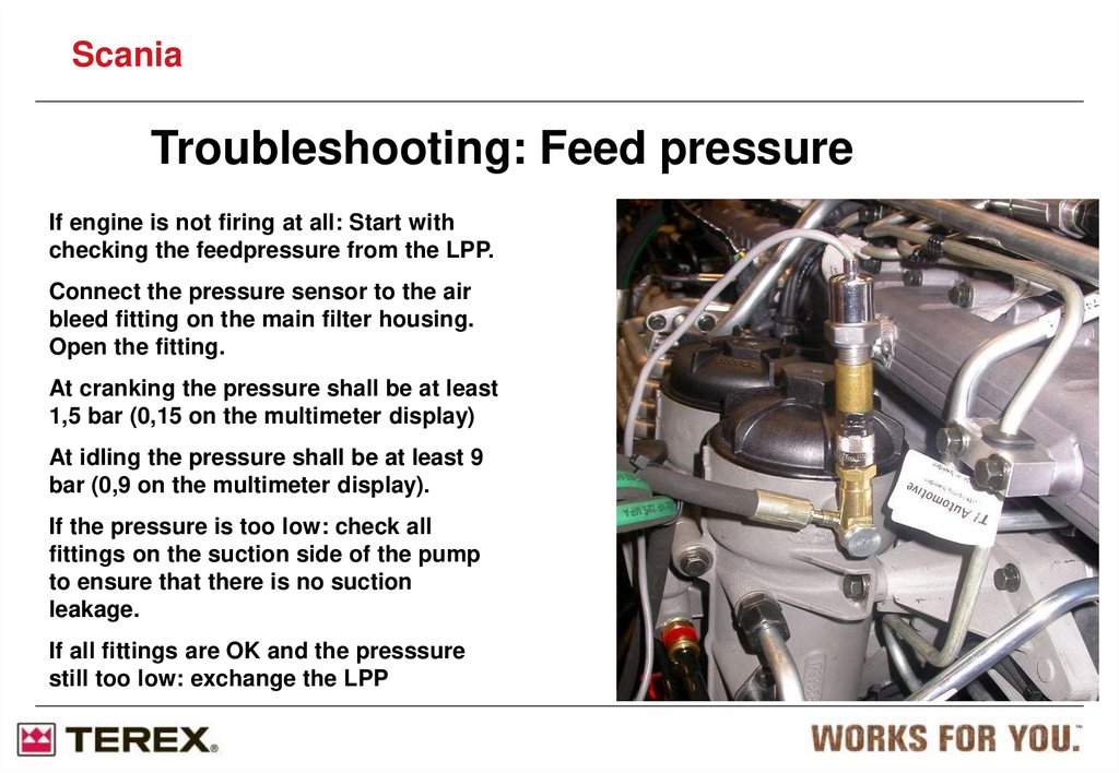
ScaniaTroubleshooting: Feed pressure
If engine is not firing at all: Start with
checking the feedpressure from the LPP.
Connect the pressure sensor to the air
bleed fitting on the main filter housing.
Open the fitting.
At cranking the pressure shall be at least
1,5 bar (0,15 on the multimeter display)
At idling the pressure shall be at least 9
bar (0,9 on the multimeter display).
If the pressure is too low: check all
fittings on the suction side of the pump
to ensure that there is no suction
leakage.
If all fittings are OK and the presssure
still too low: exchange the LPP
80.
ScaniaTroubleshooting: Fuel manifold pressure
If the railpressure is too low (fault code for low
railpressure triggered): Begin with checking all
High Pressure Line fittings for external
leakage.
If fittings are OK: Connect the pressure sensor
to the fitting on the return side of the fuel
manifold. Open the fitting.
The pressure shall not exceed 1 bar at 500 rpm
idle (hot engine).
A too high pressure indicates too high return
line flow, which indicates one or more of the
following faults:
• Pilot Valve leakage
• Cracked injector
• Worn out HPP
• Leaking HPC
81.
ScaniaFuel system, PDE
(Pumpe-Düse-Einheit)
82. Fuel system
ScaniaFuel system
1
Fuel rail
1. Fuel rail
2
2. Drain nipple
(for bleeding)
3. Fuel filter
2
4. Overflow valve
4
3
83. Fuel system
ScaniaFuel system
Fuel flow, Monorail
84. Fuel system
ScaniaFuel system Skeleton diagram of the fuel system
1. Feed pump
2. Hand pump
3. Control unit
4. Fuel filter
5. Cylinders
6. Fuel tank
7. Return pipe
A. Check valve
B. Feed pump
(gear driven)
C. Safety valve
D. Overflow valve
E. Drain nipple
85. Fuel system
ScaniaFuel system
Feed pump
Gear type
Operation pressure 4,5-7 bars
Max. suction height is 2 meters
Double action hand pump for
bleeding
86. Fuel system
ScaniaFuel system
Renewing fuel filter 1000 h.
Water separating filter
“pre-filter”
- Drainage must be carried out
when filling fuel.
- The filter must be changed at
the same replacement interval
as the main filter.
Important !
Fit the filter elements in the filter covers before placing them in the fuel
filter housings or the filter elements may be damaged.
87. Fuel system
ScaniaFuel system
Renewing fuel filter 1000 h.
Water separating filter
“pre-filter”
- Drainage must be carried out
when filling fuel.
- The filter must be changed at
the same replacement interval
as the main filter.
88. Fuel system
ScaniaFuel system
Unit injector, PDE
(Pumpe-Düse-Einheit)
Operated by the EMS-system
Engine-Management-System
1
Pump part
2
Injector section
3
Valve housing
Electrical operated
4
Zero pressure return
89. Fuel system
ScaniaFuel system
Zero pressure drain
in the PDE
90.
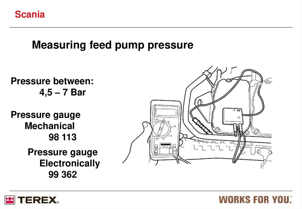
ScaniaMeasuring feed pump pressure
Pressure between:
4,5 – 7 Bar
Pressure gauge
Mechanical
98 113
Pressure gauge
Electronically
99 362
91.
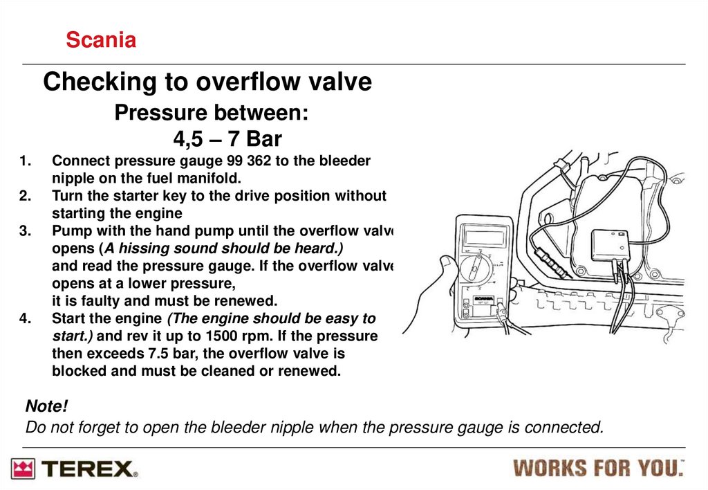
ScaniaChecking to overflow valve
Pressure between:
4,5 – 7 Bar
1.
2.
3.
4.
Connect pressure gauge 99 362 to the bleeder
nipple on the fuel manifold.
Turn the starter key to the drive position without
starting the engine
Pump with the hand pump until the overflow valve
opens (A hissing sound should be heard.)
and read the pressure gauge. If the overflow valve
opens at a lower pressure,
it is faulty and must be renewed.
Start the engine (The engine should be easy to
start.) and rev it up to 1500 rpm. If the pressure
then exceeds 7.5 bar, the overflow valve is
blocked and must be cleaned or renewed.
Note!
Do not forget to open the bleeder nipple when the pressure gauge is connected.
92.
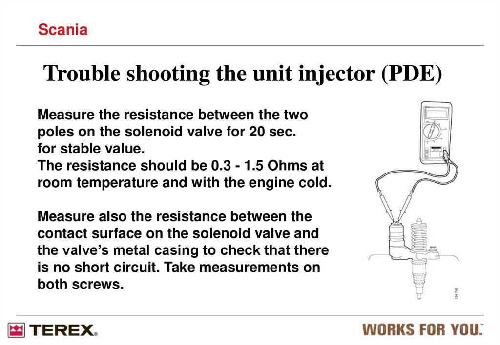
ScaniaTrouble shooting the unit injector (PDE)
Measure the resistance between the two
poles on the solenoid valve for 20 sec.
for stable value.
The resistance should be 0.3 - 1.5 Ohms at
room temperature and with the engine cold.
Measure also the resistance between the
contact surface on the solenoid valve and
the valve’s metal casing to check that there
is no short circuit. Take measurements on
both screws.
93.
ScaniaTrouble shooting the unit injector (PDE)
One of the unit injectors may be short
circuited to earth via the chassis.
This means that the EMS control unit will not
work and not provide and fault codes.
If this is the case, each unit injector must be
tested.
94. Dismantling the PDE
ScaniaDismantling the PDE
87 596
95. Dismantling the PDE
ScaniaDismantling the PDE
WARNING!
The fuel system must be
empty before dismantling the
unit injector otherwise fuel
may run down into the
cylinders, which will result in
a great risk of liquid
hammering.
If fuel runs into the
combustion chamber, it must
be removed immediately
using a pump.
96. Mounting the PDE
ScaniaMounting the PDE
Engine oil should be
used to lubricate Orings when mounting
97. Mounting the PDE
ScaniaMounting the PDE
98. Mounting the PDE
ScaniaMounting the PDE
IMPORTANT! Make sure
that the cable
terminals are the right way
round when fitting
the cables to the unit
injector.
Their relative position is
not important. Use
torque screwdriver
588 179 to tighten the
screws to 2 Nm.
99. Mounting the PDE
scaniaMounting the PDE
Tightening torque 2 +/- 0.2 Nm
IMPORTANT!
Use torque screwdriver
588179 to avoid the risk of
shearing off the screw.
The entire unit injector
must be renewed if the
screws shear off.
100. Tools for adjusting PDE
ScaniaTools for adjusting PDE
99 414 = PDE 31
99 442 = PDE 32
101. Tools for adjusting PDE
ScaniaTools for adjusting PDE
102.
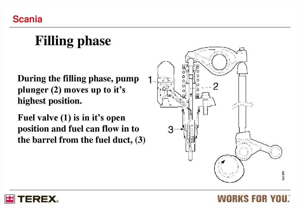
ScaniaFilling phase
During the filling phase, pump
plunger (2) moves up to it’s
highest position.
Fuel valve (1) is in it’s open
position and fuel can flow in to
the barrel from the fuel duct, (3)
103.
ScaniaSpill phase
The spill phase begins when
the camshaft starts to press
pump plunger (2).
The fuel can flow through
fuel valve (1) through the
hole in the unit injector and
out through fuel duct (3).
104.
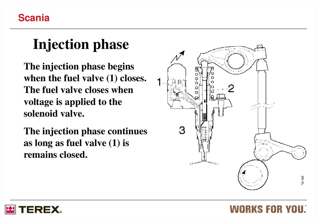
ScaniaInjection phase
The injection phase begins
when the fuel valve (1) closes.
The fuel valve closes when
voltage is applied to the
solenoid valve.
The injection phase continues
as long as fuel valve (1) is
remains closed.
105.
ScaniaPressure reduction phase
Injection stops when the fuel
valve (1) opens and the pressure
in the unit injector drops below
the nozzle’s opening pressure.
It’s the closed or open position of
the fuel valve which determines
when injection should begin and
end.
106.
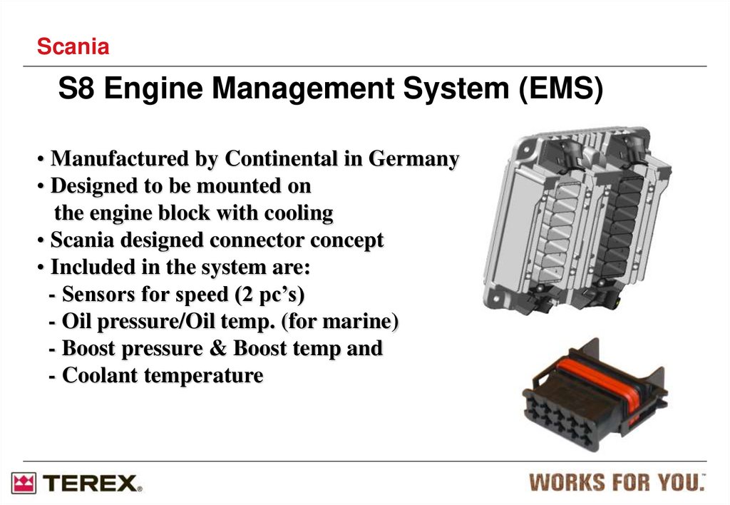
ScaniaS8 Engine Management System (EMS)
• Manufactured by Continental in Germany
• Designed to be mounted on
the engine block with cooling
• Scania designed connector concept
• Included in the system are:
- Sensors for speed (2 pc’s)
- Oil pressure/Oil temp. (for marine)
- Boost pressure & Boost temp and
- Coolant temperature
107.
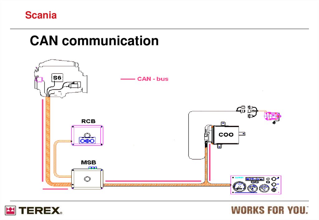
ScaniaCAN communication
108.
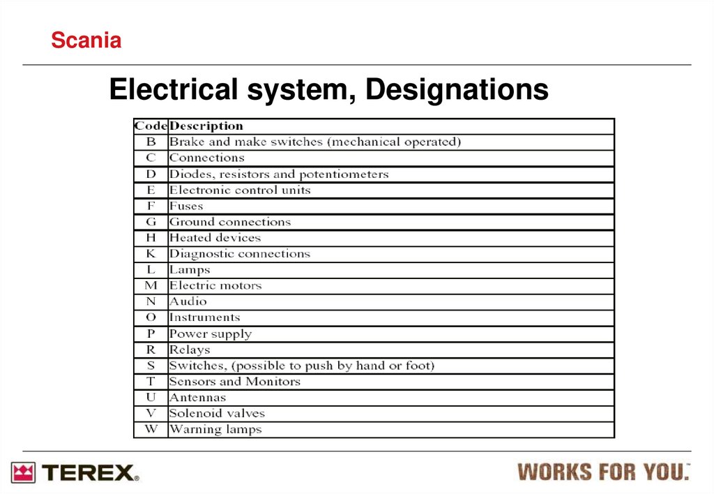
ScaniaElectrical system, Designations
109.
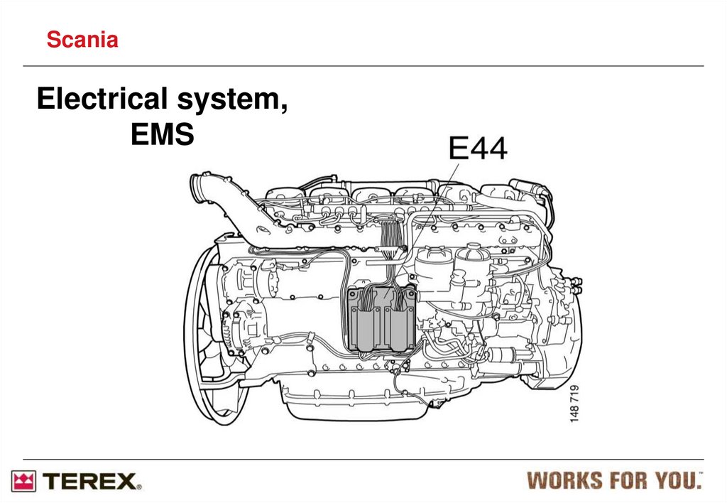
ScaniaElectrical system,
EMS
110.
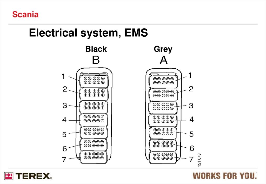
ScaniaElectrical system, EMS
Black
Grey
111.
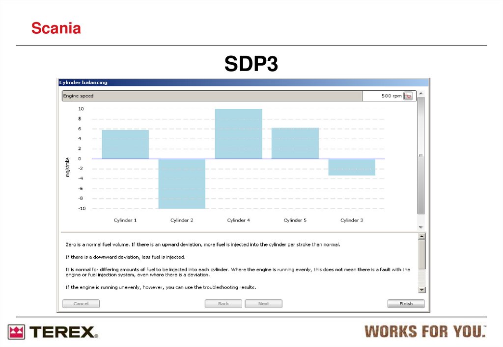
111112. SDP3 Engine Diagnostic
ScaniaSDP3 Engine Diagnostic
15504875
15504817
15504818
15504815
15504816
Software: SDP3
Source: Terex, Part No: 15504815
Cost: £????
USB Key: 15504816
Cost: £???? Annual Subscription
Library Files: N/A
113.
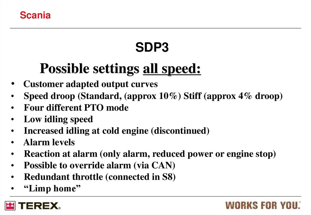
ScaniaSDP3
Possible settings all speed:
• Customer adapted output curves
Speed droop (Standard, (approx 10%) Stiff (approx 4% droop)
Four different PTO mode
Low idling speed
Increased idling at cold engine (discontinued)
Alarm levels
Reaction at alarm (only alarm, reduced power or engine stop)
Possible to override alarm (via CAN)
Redundant throttle (connected in S8)
“Limp home”
114.
ScaniaGeneric Cable Colours
There are also cables marked with two
colours, e.g. YE/WH. The above table
provides all possible combinations.
115.
ScaniaCylinder output test
- Mainly used to detect faulty injectors.
- Engine must run at no load and be
internally synchronized.
- Engine temperature should be >50oC
116.
ScaniaCylinder output test
The engine revs up to a fixed (1800) RPM with a fixed
fuel amount.
- All cylinders except one are cut off.
- RPM drops, and time is measured between two
fixed RPMs.
- The test is repeated for all cylinders a number of times.
- The result is time. (look for the most prominent)
117.
ScaniaCylinder output test
118.
ScaniaCylinder output test
Short time could indicate:
- Bad injector.
- Low compression
- Seized piston
119.
ScaniaSDP3
120.
ScaniaCompression test
Engine must run at no load and be internally synchronized.
- Engine temperature should be >50 oC
- U15 must be ”ON” during the test. (gen-sets might need a bypass)
- Starter motor must be controlled by EMS and CAN-start
activated.
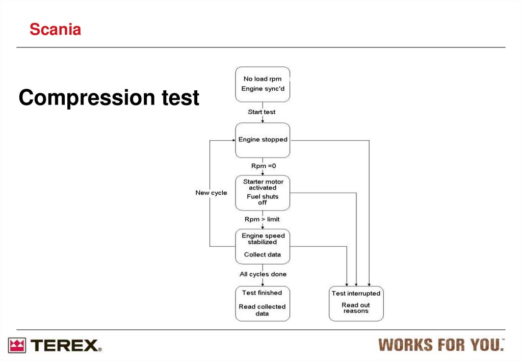
121.
ScaniaCompression test
122.
ScaniaCompression test
The result is speed. (look for the most prominent)
- High speed could indicate low compression.
- Low speed could indicate seized piston.
- Main reason for failed test is weak batteries.
123. Fuel heater XPI
ScaniaFuel heater XPI
Deutsch contact DTP04-2P
Max 350W
Thermostat with working range
5°C - 24°C
124. Customer interface
ScaniaCustomer interface
EMS
VCI
SCR/EGR
1.C4001
2.C4000
3.C4002
EMS control unit
Diagnostics
SCR or EGR system
125. EMS contact C4001
ScaniaEMS contact C4001
4.
3.
2.
1.
Supply U30
Ignition U15
Ground U31
Supply U30
5.
6.
7.
8.
Ground U31
CAN high
CAN low
Engine running status
SCR contact C4002
4.
5.
6.
Tank level lamp (GND)
SCR error lamp (+24V)
SCR error lamp (GND)
3.
2.
1.
Tank level lamp (+24V)
Not used
Ignition U15
126.
ScaniaEMS parameter settings
Altitude power reduction