


 Механика
Похожие презентации:


Fuel supply system DC9 EDC MS5
1.
Fuel supply system DC9 EDC MS5Eddy Deprez
+32 2 722 86 89
SWBTC_XXX_3_3_1_3_EN
Links
Issue 2004-09-06
Replace 2003-06-24
eddy.deprez@scania.be
P. 1
Exit
Report
Go to test
Supply system DC 9
Web based
pre-knowledge
technical course
This course relates to the components of the supply system
fitted with DC 9 (EDC MS5) engines originally fitted in
production on series 4 trucks.
Principal objectives
This online training forms an integrated part of the Scania EDC
MS5 course. This module is (or is part of) advance theoretical
knowledge needed before being able to take part in the
practical course supervised by an instructor. It is essential that
you have a perfect command of the contents of this course as
the instructor will not repeat these basics. The condition for
being able to take part in the practical course is success in the
final test of this module.
Estimated duration of the training: 1 hr
Remarks
2.
Fuel supply system DC9 EDC MS5Eddy Deprez
+32 2 722 86 89
SWBTC_XXX_3_3_1_3_EN
Links
Issue 2004-09-06
Replace 2003-06-24
eddy.deprez@scania.be
P. 2
Exit
Web based
pre-knowledge
technical course
Report
Go to test
Self-assessment
This module starts with a self-assessment. This means
that you must complete the questionnaire before being
able to begin the course. The result will show you the
knowledge you already have and of what must be
focused on individually. Using the answer “Skip
question” at the appropriate time is highly
recommended. Do not answer randomly... these
questions will return during the final test.
Important
The self-assessment can be accessed only once. The
assessment can only be exited by finishing it. The results will be
disclosed to you after the tests. You have a time limit per
question.
The estimated total duration of the self-assessment is 5 minutes.
Good luck!
Start the self-assessment
Remarks
3.
Fuel supply system DC9 EDC MS5Eddy Deprez
+32 2 722 86 89
SWBTC_XXX_3_3_1_3_EN
Links
Issue 2004-09-06
Replace 2003-06-24
eddy.deprez@scania.be
P. 3
Chapter 1 estimated time …….
Exit
Report
Go to test
Chapter 1
This chapter introduces the basic
theory, the functionality and
location of the supply system
components
Remarks
4.
Fuel supply system DC9 EDC MS5Eddy Deprez
+32 2 722 86 89
SWBTC_XXX_3_3_1_3_EN
Links
Replace 2003-06-24
eddy.deprez@scania.be
P. 4
Module 1
estimated time …….
Exit
Report
Go to test
Chapter 1
1. System structure
This module introduces
the general structure of
the fuel supply system
Remarks
Issue 2004-09-06
5.
Fuel supply system DC9 EDC MS5Eddy Deprez
+32 2 722 86 89
eddy.deprez@scania.be
1. Module title
Remarks
The fuel system
consists of a fuel
tank (2) with fuel
pick-up unit (1), fuel
lines (10), a fuel
pump (4), a fuel
filter (5) an injection
pump (6) equipped
with a fuel valve (7)
and a return valve
(11), as well as
injectors (9) and
return pipes (12).
Exit
Report
Issue 2004-09-06
Replace 2003-06-24
Text WSM 03:01-01 page 4 modified
Picture 120 444 modified
Module 1, page 1
Chapter 1
SWBTC_XXX_3_3_1_3_EN
P. 5
Go to test
6.
Fuel supply system DC9 EDC MS5Eddy Deprez
+32 2 722 86 89
SWBTC_XXX_3_3_1_3_EN
Text WSM 03:01-01 page 4 - 5
Picture 120 444
Issue 2004-09-06
Replace 2003-06-24
eddy.deprez@scania.be
P. 6
Module 1, page 2
Exit
Report
Go to test
Chapter 1
1. Module title
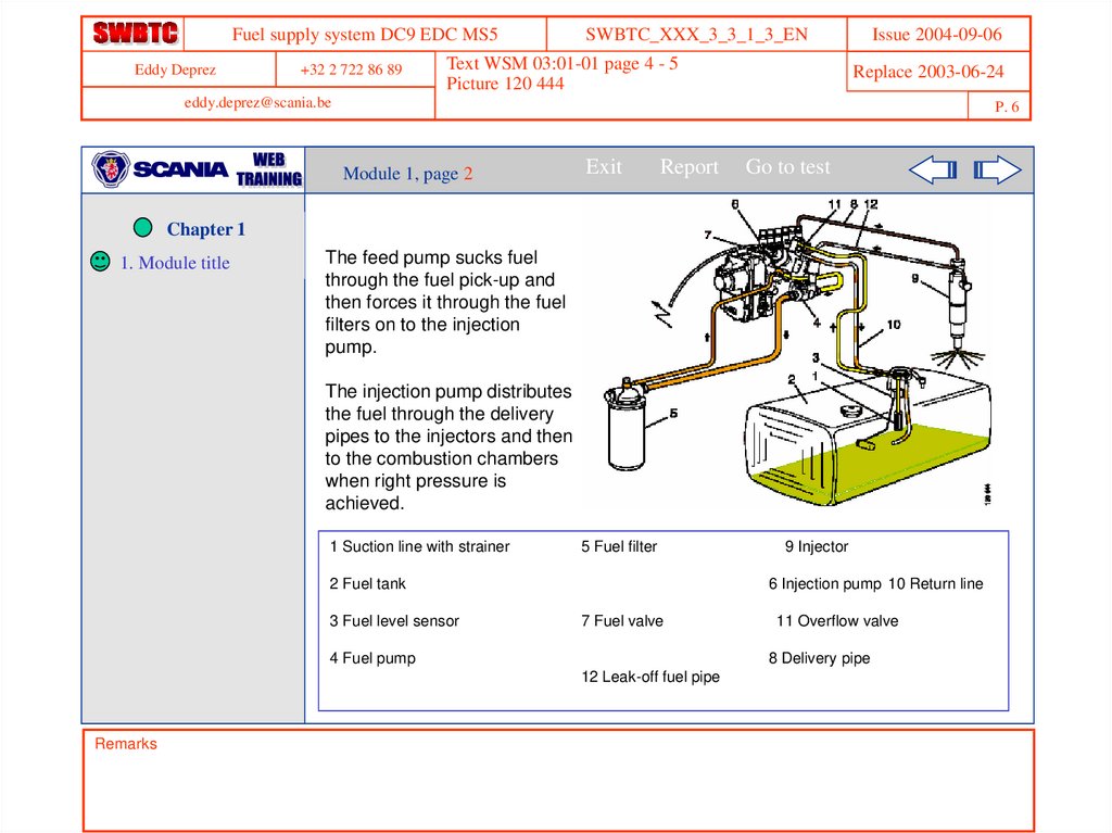
The feed pump sucks fuel
through the fuel pick-up and
then forces it through the fuel
filters on to the injection
pump.
The injection pump distributes
the fuel through the delivery
pipes to the injectors and then
to the combustion chambers
when right pressure is
achieved.
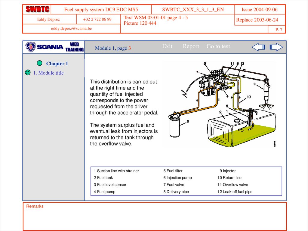
1 Suction line with strainer
5 Fuel filter
2 Fuel tank
3 Fuel level sensor
6 Injection pump 10 Return line
7 Fuel valve
4 Fuel pump
11 Overflow valve
8 Delivery pipe
12 Leak-off fuel pipe
Remarks
9 Injector
7.
Fuel supply system DC9 EDC MS5Eddy Deprez
+32 2 722 86 89
SWBTC_XXX_3_3_1_3_EN
Text WSM 03:01-01 page 4 - 5
Picture 120 444
Issue 2004-09-06
Replace 2003-06-24
eddy.deprez@scania.be
P. 7
Module 1, page 3
Exit
Report
Go to test
Chapter 1
1. Module title
This distribution is carried out
at the right time and the
quantity of fuel injected
corresponds to the power
requested from the driver
through the accelerator pedal.
The system surplus fuel and
eventual leak from injectors is
returned to the tank through
the overflow valve.
Remarks
1 Suction line with strainer
5 Fuel filter
9 Injector
2 Fuel tank
6 Injection pump
10 Return line
3 Fuel level sensor
7 Fuel valve
11 Overflow valve
4 Fuel pump
8 Delivery pipe
12 Leak-off fuel pipe
8.
Fuel supply system DC9 EDC MS5Eddy Deprez
+32 2 722 86 89
SWBTC_XXX_3_3_1_3_EN
Issue 2004-09-06
Replace 2003-06-24
TEC 00.01.01.11-01 question 16
eddy.deprez@scania.be
P. 8
Module 1
Chapter 1
1. Module title
Exit
Report
Go to test
Question 1 (45 sec)
In the supply circuit, what is the feed pump used for?
To draw the fuel from the injectors.
To bleed the supply circuit.
To draw the fuel from the fuel filter and send it into the circuit.
To draw the fuel from the tank and supply the system with fuel.
Skip Question
Wrong answer. The correct answer is in this module on page 1.
Remarks
9.
Fuel supply system DC9 EDC MS5Eddy Deprez
+32 2 722 86 89
SWBTC_XXX_3_3_1_3_EN
Links
Replace 2003-06-24
eddy.deprez@scania.be
P. 9
Module 2
estimated time …….
Exit
Report
Go to test
Chapter 1
1.
Module title
2.
Fuel tank and
lines
This module introduces the
components of the fuel tank
and lines
Remarks
Issue 2004-09-06
10.
Fuel supply system DC9 EDC MS5Eddy Deprez
+32 2 722 86 89
eddy.deprez@scania.be
Text WSM 03:01-01 page 6 modified
Picture 03_0262 WSM 03:01-01 page 6
Module 2, page 1
Chapter 1
1. Module title
2. Module title
SWBTC_XXX_3_3_1_3_EN
Exit
Report
Go to test
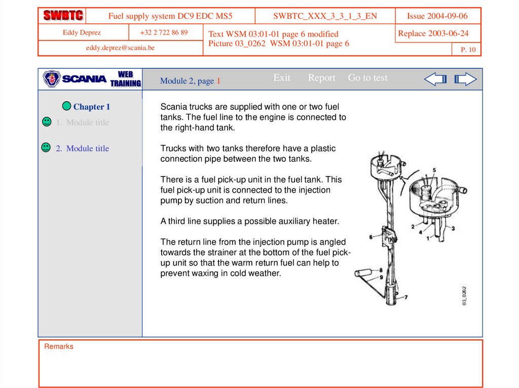
Scania trucks are supplied with one or two fuel
tanks. The fuel line to the engine is connected to
the right-hand tank.
Trucks with two tanks therefore have a plastic
connection pipe between the two tanks.
There is a fuel pick-up unit in the fuel tank. This
fuel pick-up unit is connected to the injection
pump by suction and return lines.
A third line supplies a possible auxiliary heater.
The return line from the injection pump is angled
towards the strainer at the bottom of the fuel pickup unit so that the warm return fuel can help to
prevent waxing in cold weather.
Remarks
Issue 2004-09-06
Replace 2003-06-24
P. 10
11.
Fuel supply system DC9 EDC MS5Eddy Deprez
+32 2 722 86 89
eddy.deprez@scania.be
1. Module title
2. Module title
Exit
Report
Issue 2004-09-06
Replace 2003-06-24
Text WSM 03:01-01 page 6
Picture 03_0253 WSM 03:01-01 page 6
Module 2, page 2
Chapter 1
SWBTC_XXX_3_3_1_3_EN
P. 11
Go to test
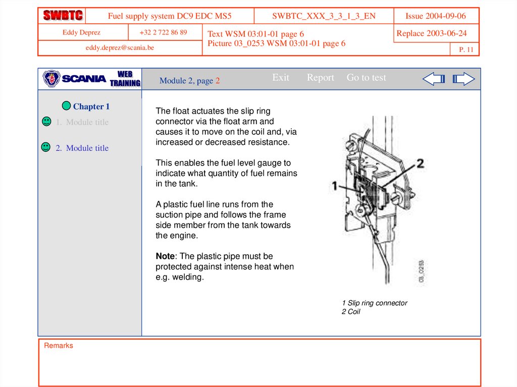
The float actuates the slip ring
connector via the float arm and
causes it to move on the coil and, via
increased or decreased resistance.
This enables the fuel level gauge to
indicate what quantity of fuel remains
in the tank.
A plastic fuel line runs from the
suction pipe and follows the frame
side member from the tank towards
the engine.
Note: The plastic pipe must be
protected against intense heat when
e.g. welding.
1 Slip ring connector
2 Coil
Remarks
12.
Fuel supply system DC9 EDC MS5Eddy Deprez
+32 2 722 86 89
SWBTC_XXX_3_3_1_3_EN
Issue 2004-09-06
Replace 2003-06-24
New question
eddy.deprez@scania.be
P. 12
Exit
Module 2
Chapter 1
1. Module title
2. Module title
Report
Go to test
Question 1 (40 sec)
A vehicle fitted with two tanks is equipped with:
An electric pump which automatically transfers the fuel over to the righthand tank.
A return and suction line on each tank.
A plastic connection pipe between the tanks.
Two valves which the driver must control according to the status of the
tanks.
Skip Question
Wrong answer. The correct answer is in this module on page 1.
Remarks
13.
Fuel supply system DC9 EDC MS5Eddy Deprez
+32 2 722 86 89
SWBTC_XXX_3_3_1_3_EN
Issue 2004-09-06
Replace 2003-06-24
New question
eddy.deprez@scania.be
P. 13
Module 2
Chapter 1
Exit
Report
Go to test
Question 2 (40 sec)
1. Module title
The return pipe coming from the injection pump is angled towards
the strainer at the fuel pick-up unit with the aim of:
2. Module title
To avoid a too significant heating of the tank walls.
Avoiding splashes and then the formation of air bubbles.
Warm fuel helping to prevent waxing in the event of freezing.
Drawing the cleanest possible fuel in order to lengthen the service life of
the fuel filter.
Skip Question
Wrong answer. The correct answer is in this module on page 1.
Remarks
14.
Fuel supply system DC9 EDC MS5Eddy Deprez
+32 2 722 86 89
SWBTC_XXX_3_3_1_3_EN
Links
Issue 2004-09-06
Replace 2003-06-24
eddy.deprez@scania.be
P. 14
Module 3
estimated time …….
Exit
Report
Go to test
Chapter 1
1.
Module title
2.
Module title
3.
Fuel valve
Remarks
This module introduces the
fuel valve, as well as its location
on the vehicle
15.
Fuel supply system DC9 EDC MS5Eddy Deprez
+32 2 722 86 89
eddy.deprez@scania.be
1. Module title
2. Module title
3. Module title
Exit
Report
Issue 2004-09-06
Replace 2003-06-24
Text WSM 03:01-01 page 7
Picture 03_0800 WSM 03:01-01 page 7
Module 3, page 1
Chapter 1
SWBTC_XXX_3_3_1_3_EN
P. 15
Go to test
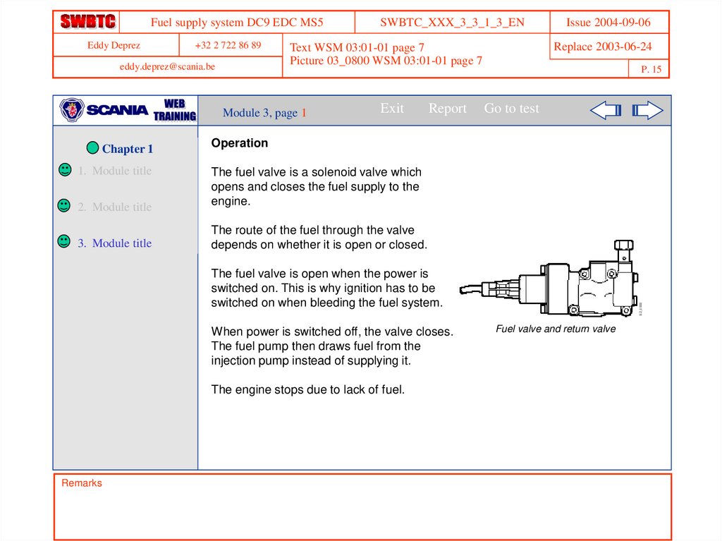
Operation
The fuel valve is a solenoid valve which
opens and closes the fuel supply to the
engine.
The route of the fuel through the valve
depends on whether it is open or closed.
The fuel valve is open when the power is
switched on. This is why ignition has to be
switched on when bleeding the fuel system.
When power is switched off, the valve closes.
The fuel pump then draws fuel from the
injection pump instead of supplying it.
The engine stops due to lack of fuel.
Remarks
Fuel valve and return valve
16.
Fuel supply system DC9 EDC MS5Eddy Deprez
+32 2 722 86 89
eddy.deprez@scania.be
1. Module title
2. Module title
3. Module title
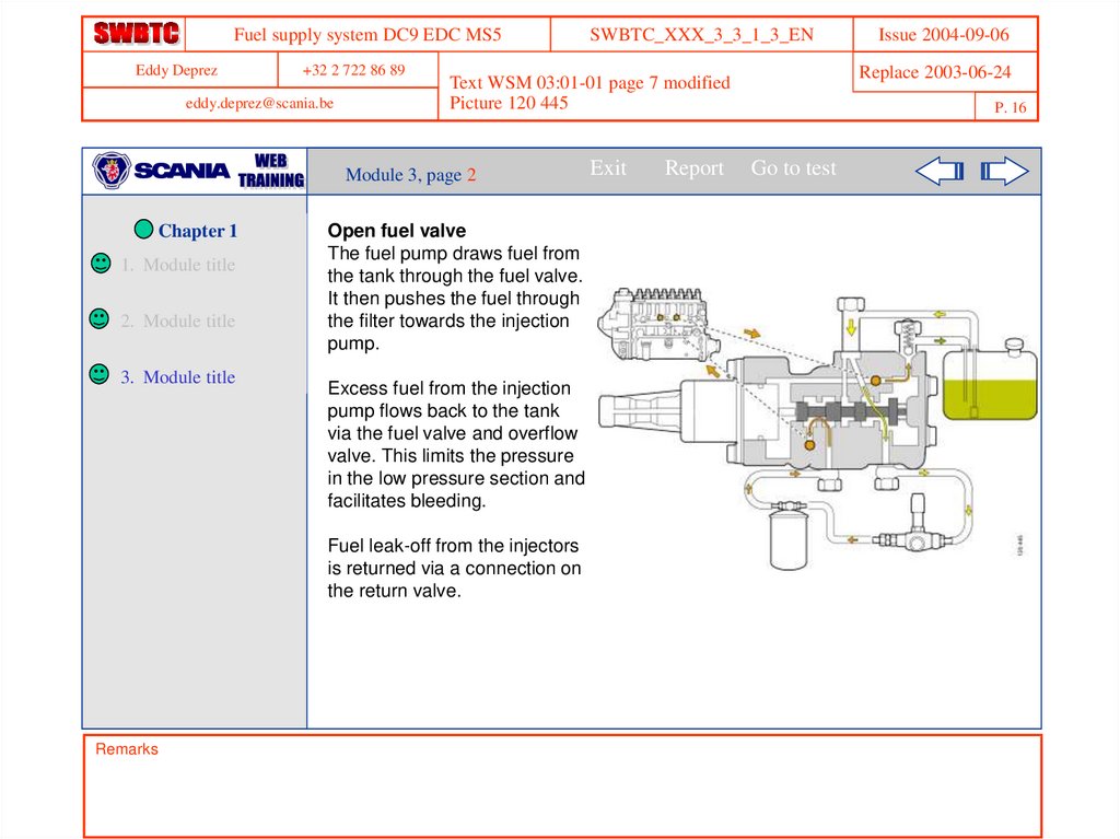
Open fuel valve
The fuel pump draws fuel from
the tank through the fuel valve.
It then pushes the fuel through
the filter towards the injection
pump.
Excess fuel from the injection
pump flows back to the tank
via the fuel valve and overflow
valve. This limits the pressure
in the low pressure section and
facilitates bleeding.
Fuel leak-off from the injectors
is returned via a connection on
the return valve.
Remarks
Exit
Report
Issue 2004-09-06
Replace 2003-06-24
Text WSM 03:01-01 page 7 modified
Picture 120 445
Module 3, page 2
Chapter 1
SWBTC_XXX_3_3_1_3_EN
P. 16
Go to test
17.
Fuel supply system DC9 EDC MS5Eddy Deprez
+32 2 722 86 89
eddy.deprez@scania.be
1. Module title
2. Module title
3. Module title
Remarks
Exit
Issue 2004-09-06
Replace 2003-06-24
Text WSM 03:01-01 page 8
Picture 120 446
Module 3, page 3
Chapter 1
SWBTC_XXX_3_3_1_3_EN
P. 17
Report
Go to test
Closed fuel valve
The fuel pump draws fuel from the injection pump through the fuel valve. It then
forces the fuel through the filter towards the tank.
18.
Fuel supply system DC9 EDC MS5Eddy Deprez
+32 2 722 86 89
SWBTC_XXX_3_3_1_3_EN
Issue 2004-09-06
Replace 2003-06-24
TEC 00.01.01.11-01 question 12
eddy.deprez@scania.be
P. 18
Module 3
Chapter 1
1. Module title
Exit
Report
Go to test
Question 1 (40 sec)
In the supply circuit, what is the overflow valve used for?
2. Module title
To reduce the risk of overpressure in the fuel pump.
3. Module title
To increase the pressure of the fuel pump.
To limit the pressure in the low pressure section and to bleed the circuit.
To drive excess fuel past the fuel pump.
Skip Question
Wrong answer. The correct answer is in this module on page 2.
Remarks
19.
Fuel supply system DC9 EDC MS5Eddy Deprez
+32 2 722 86 89
SWBTC_XXX_3_3_1_3_EN
Issue 2004-09-06
Replace 2003-06-24
New question
eddy.deprez@scania.be
P. 19
Module 3
Chapter 1
1. Module title
Exit
Report
Go to test
Question 2 (40 sec)
During the bleeding of the fuel system, it is necessary:
2. Module title
To fit the tank plug.
3. Module title
To have the starter key on.
To fill the filter with fuel before positioning it on the bracket.
To remove the overflow valve.
Skip Question
Wrong answer. The correct answer is in this module on page 1.
Remarks
20.
Fuel supply system DC9 EDC MS5Eddy Deprez
+32 2 722 86 89
SWBTC_XXX_3_3_1_3_EN
Links
Replace 2003-06-24
eddy.deprez@scania.be
P. 20
Module 4
estimated time …….
Exit
Report
Go to test
Chapter 1
1.
Module title
2.
Module title
3.
Module title
4.
Fuel pump
Remarks
Issue 2004-09-06
This module introduces the
fuel pump, as well as its
location on the vehicle
21.
Fuel supply system DC9 EDC MS5Eddy Deprez
+32 2 722 86 89
eddy.deprez@scania.be
1. Module title
Exit
Report
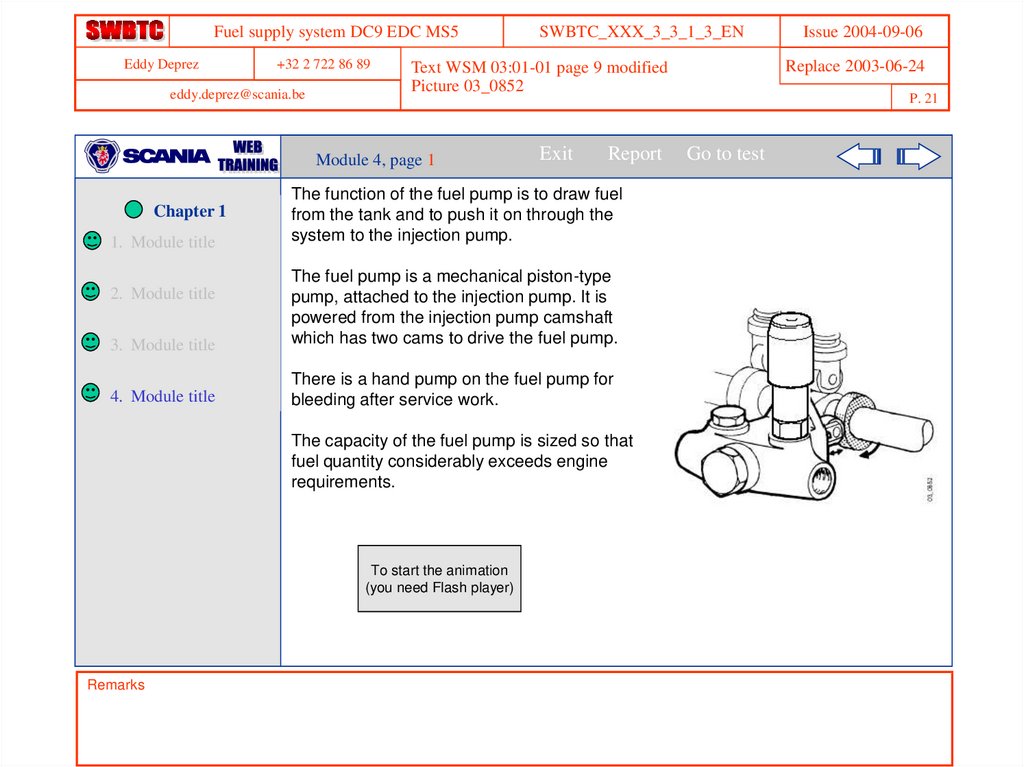
The function of the fuel pump is to draw fuel
from the tank and to push it on through the
system to the injection pump.
3. Module title
The fuel pump is a mechanical piston-type
pump, attached to the injection pump. It is
powered from the injection pump camshaft
which has two cams to drive the fuel pump.
4. Module title
There is a hand pump on the fuel pump for
bleeding after service work.
2. Module title
The capacity of the fuel pump is sized so that
fuel quantity considerably exceeds engine
requirements.
To start the animation
(you need Flash player)
Démarrer l ’animation
Remarks
Issue 2004-09-06
Replace 2003-06-24
Text WSM 03:01-01 page 9 modified
Picture 03_0852
Module 4, page 1
Chapter 1
SWBTC_XXX_3_3_1_3_EN
P. 21
Go to test
22.
Fuel supply system DC9 EDC MS5Eddy Deprez
+32 2 722 86 89
eddy.deprez@scania.be
Chapter 1
1. Module title
3. Module title
4. Module title
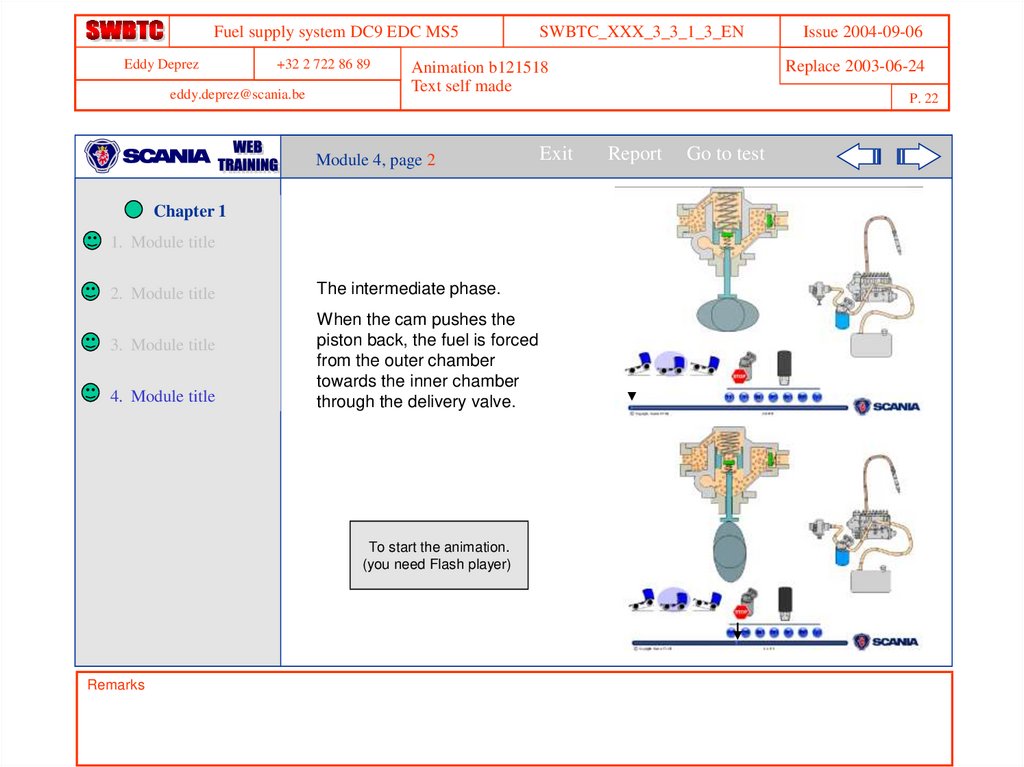
The intermediate phase.
When the cam pushes the
piston back, the fuel is forced
from the outer chamber
towards the inner chamber
through the delivery valve.
To start the animation.
(you need Flash player)
Remarks
Exit
Issue 2004-09-06
Replace 2003-06-24
Animation b121518
Text self made
Module 4, page 2
2. Module title
SWBTC_XXX_3_3_1_3_EN
P. 22
Report
Go to test
23.
Fuel supply system DC9 EDC MS5Eddy Deprez
+32 2 722 86 89
eddy.deprez@scania.be
SWBTC_XXX_3_3_1_3_EN
Exit
Chapter 1
1. Module title
2. Module title
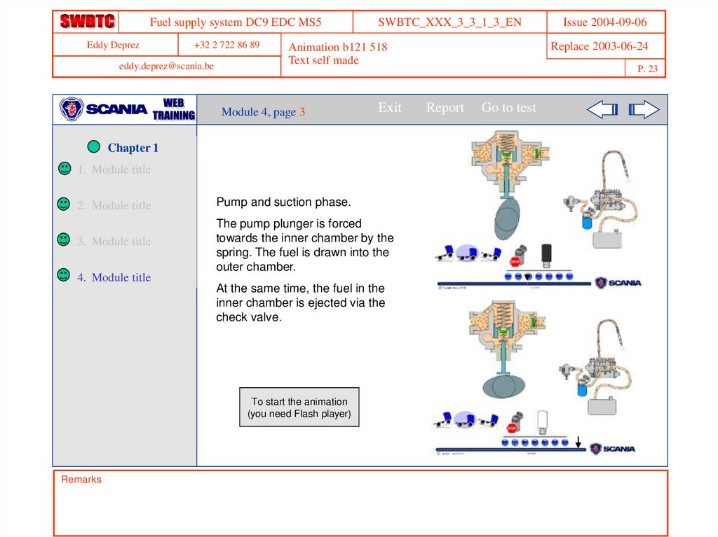
Pump and suction phase.
3. Module title
The pump plunger is forced
towards the inner chamber by the
spring. The fuel is drawn into the
outer chamber.
4. Module title
At the same time, the fuel in the
inner chamber is ejected via the
check valve.
To start the animation
(you need Flash player)
Remarks
Replace 2003-06-24
Animation b121 518
Text self made
Module 4, page 3
Issue 2004-09-06
P. 23
Report
Go to test
24.
Fuel supply system DC9 EDC MS5Eddy Deprez
+32 2 722 86 89
SWBTC_XXX_3_3_1_3_EN
Issue 2004-09-06
Replace 2003-06-24
New question
eddy.deprez@scania.be
P. 24
Module 4
Chapter 1
Exit
Report
Go to test
Question 1 (40 sec)
1. Module title
The fuel pump is equipped with a hand pump. This is intended to:
2. Module title
Introduce lubrication fluid.
3. Module title
Facilitate starting in cold weather.
4. Module title
Enable bleeding of the circuit after service work.
Check the sealing of the supply circuit.
Skip Question
Wrong answer. The correct answer is in this module on page 1.
Remarks
25.
Fuel supply system DC9 EDC MS5Eddy Deprez
+32 2 722 86 89
SWBTC_XXX_3_3_1_3_EN
Links
Issue 2004-09-06
Replace 2003-06-24
eddy.deprez@scania.be
P. 25
Module 5
estimated time …….
Exit
Report
Go to test
Chapter 1
1.
Module title
2.
Module title
3.
Module title
4.
Module title
5.
Fuel filter
Remarks
This module introduces the fuel
filter, as well as its location on
the vehicle
26.
Fuel supply system DC9 EDC MS5Eddy Deprez
+32 2 722 86 89
eddy.deprez@scania.be
SWBTC_XXX_3_3_1_3_EN
Exit
Chapter 1
1. Module title
2. Module title
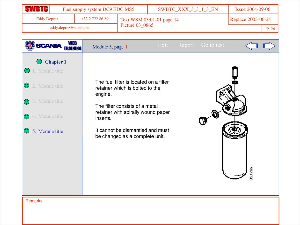
The fuel filter is located on a filter
retainer which is bolted to the
engine.
3. Module title
4. Module title
5. Module title
Remarks
Replace 2003-06-24
Text WSM 03:01-01 page 14
Picture 03_0865
Module 5, page 1
The filter consists of a metal
retainer with spirally wound paper
inserts.
It cannot be dismantled and must
be changed as a complete unit.
Report
Issue 2004-09-06
P. 26
Go to test
27.
Fuel supply system DC9 EDC MS5Eddy Deprez
+32 2 722 86 89
SWBTC_XXX_3_3_1_3_EN
Issue 2004-09-06
Replace 2003-06-24
New question
eddy.deprez@scania.be
P. 27
Module 5
Chapter 1
Exit
Report
Go to test
Question 1 (30 sec)
1. Module title
Is it possible to replace just the paper cartridge of the filter?
2. Module title
Yes
3. Module title
No
4. Module title
Yes, but only for M service.
5. Module title
Skip Question
Wrong answer. The correct answer is in this module on page 1.
Remarks
28.
Fuel supply system DC9 EDC MS5Eddy Deprez
+32 2 722 86 89
SWBTC_XXX_3_3_1_3_EN
New
Issue 2004-09-06
Replace 2003-06-24
eddy.deprez@scania.be
P. 28
Chapter 1
Exit
Report
Go to test
Chapter 1
1. Module title
2. Module title
In this chapter you learned:
3. Module title
The general structure of the fuel
supply system as well as specific
details of principal components.
4. Module title
5. Module title
Remarks
Do not forget that the connection
must be actuated in order to allow the
bleeding of the circuit, without which
the fuel valve blocks the passage of
fuel.
29.
Fuel supply system DC9 EDC MS5Eddy Deprez
+32 2 722 86 89
SWBTC_XXX_3_3_1_3_EN
Links
Issue 2004-09-06
Replace 2003-06-24
eddy.deprez@scania.be
P. 29
Chapter 2 estimated time …….
Exit
Report
Go to test
Chapter 2
This chapter introduces the
injection pump and the injectors
Remarks
30.
Fuel supply system DC9 EDC MS5Eddy Deprez
+32 2 722 86 89
SWBTC_XXX_3_3_1_3_EN
Links
Replace 2003-06-24
eddy.deprez@scania.be
P. 30
Module 1
estimated time ...
Exit
Report
Go to test
Chapter 2
1. Injection pump
This module introduces the
injection pump
Remarks
Issue 2004-09-06
31.
Fuel supply system DC9 EDC MS5Eddy Deprez
+32 2 722 86 89
eddy.deprez@scania.be
1. Module title
Exit
The injection pump is driven from
the engine timing gear. The
injection pump camshaft has a hub
with a gear wheel.
Exchange ratio is such that the
injection pump is driven at half
engine speed.
Injection pump bearings, camshaft
and tappets are lubricated with oil
from the engine lubricating system.
The pump elements are lubricated
with fuel.
The injection pump has one pump
element for each engine cylinder.
The pump elements always have
the same stroke.
Remarks
Report
Issue 2004-09-06
Replace 2003-06-24
Text WSM 03:01-01 page 15
Picture 03_0789
Module 1, page 1
Chapter 2
SWBTC_XXX_3_3_1_3_EN
P. 31
Go to test
32.
Fuel supply system DC9 EDC MS5Eddy Deprez
+32 2 722 86 89
eddy.deprez@scania.be
1. Module title
Exit
Issue 2004-09-06
Replace 2003-06-24
Text WSM 03:01-01 page 15
Picture 03_0259
Module 1, page 2
Chapter 2
SWBTC_XXX_3_3_1_3_EN
P. 32
Report
Go to test
Injection quantity is determined
by how much the plunger in the
pump element is turned.
Mechanically, the pump plunger
is turned by the control rack
which is controlled by the
governor.
All plungers are turned at the
same time and by the same
amount.
Injection starts when the pump
plunger closes the inlet and spill
ports in the pump element. The
control edge of the pump plunger
is chamfered.
Injection ceases when this
chamfered control edge passes
the spill port in the pump barrel.
Remarks
a = Fuel quantity in relation to control
rack and pump element position
33.
Fuel supply system DC9 EDC MS5Eddy Deprez
+32 2 722 86 89
SWBTC_XXX_3_3_1_3_EN
Text WSM 03:01-01 page 16 modified
Picture 03_0296 modified (arrows + text)
eddy.deprez@scania.be
Exit
Report
Go to test
Chapter 2
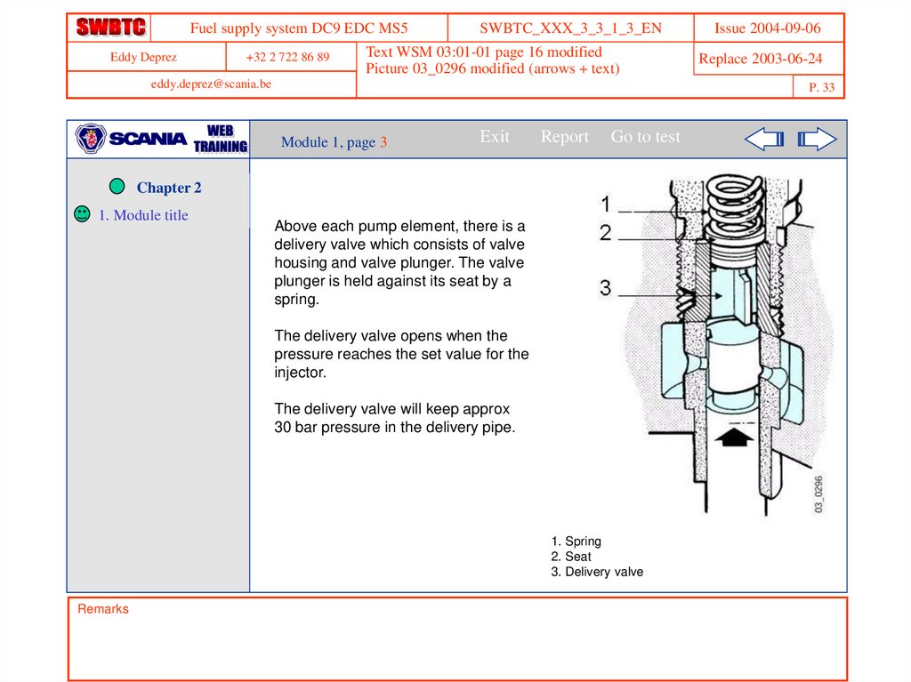
Above each pump element, there is a
delivery valve which consists of valve
housing and valve plunger. The valve
plunger is held against its seat by a
spring.
The delivery valve opens when the
pressure reaches the set value for the
injector.
The delivery valve will keep approx
30 bar pressure in the delivery pipe.
1. Spring
2. Seat
3. Delivery valve
Remarks
Replace 2003-06-24
P. 33
Module 1, page 3
1. Module title
Issue 2004-09-06
34.
Fuel supply system DC9 EDC MS5Eddy Deprez
+32 2 722 86 89
SWBTC_XXX_3_3_1_3_EN
Text WSM 03:01-01 page 16 modified
Picture 03_0296 modified (arrows + text)
eddy.deprez@scania.be
Exit
Report
Go to test
Chapter 2
When the delivery valve plunger has
closed, the available volume for the
fuel in the delivery pipe increases.
This lowers the pressure in the
delivery pipe and injectors,
decreasing the risk of flowing out
from the injector.
The change in capacity is adapted to
the length of the delivery pipe and this
length must never be changed. The
delivery valve is held in the pump
housing by the delivery valve holder,
which is bolted into the housing from
above.
1. Spring
2. Seat
3. Delivery valve
Remarks
Replace 2003-06-24
P. 34
Module 1, page 4
1. Module title
Issue 2004-09-06
35.
Fuel supply system DC9 EDC MS5Eddy Deprez
+32 2 722 86 89
eddy.deprez@scania.be
Exit
Report
Issue 2004-09-06
Replace 2003-06-24
Text WSM 03:01-01 page 17 modified
Picture 03_0264 + 03_0265
Module 1, page 5
Chapter 2
SWBTC_XXX_3_3_1_3_EN
P. 35
Go to test
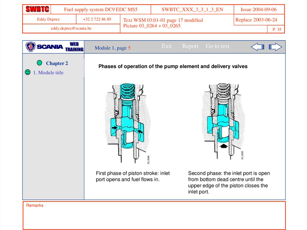
Phases of operation of the pump element and delivery valves
1. Module title
First phase of piston stroke: inlet
port opens and fuel flows in.
Remarks
Second phase: the inlet port is open
from bottom dead centre until the
upper edge of the piston closes the
inlet port.
36.
Fuel supply system DC9 EDC MS5Eddy Deprez
+32 2 722 86 89
eddy.deprez@scania.be
SWBTC_XXX_3_3_1_3_EN
Replace 2003-06-24
Text WSM 03:01-01 page 18
Picture 03_0266 and 03_0267
Module 1, page 6
Exit
Report
Issue 2004-09-06
P. 36
Go to test
Chapter 2
1. Module title
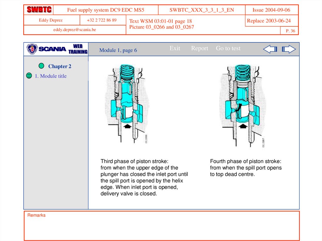
Third phase of piston stroke:
from when the upper edge of the
plunger has closed the inlet port until
the spill port is opened by the helix
edge. When inlet port is opened,
delivery valve is closed.
Remarks
Fourth phase of piston stroke:
from when the spill port opens
to top dead centre.
37.
Fuel supply system DC9 EDC MS5Eddy Deprez
+32 2 722 86 89
eddy.deprez@scania.be
SWBTC_XXX_3_3_1_3_EN
Replace 2003-06-24
Text WSM 03:01-01 page 18
Picture 03_0296
Module 1, page 7
Exit
P. 37
Report
Go to test
Chapter 2
1. Module title
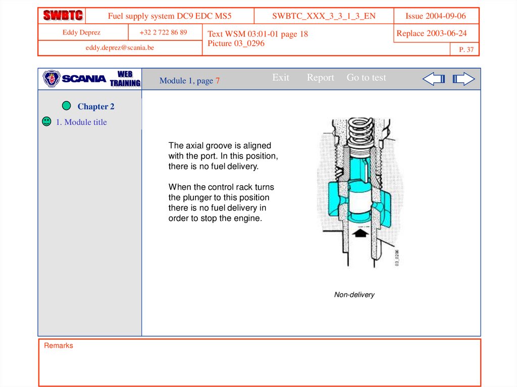
The axial groove is aligned
with the port. In this position,
there is no fuel delivery.
When the control rack turns
the plunger to this position
there is no fuel delivery in
order to stop the engine.
Non-delivery
Remarks
Issue 2004-09-06
38.
Fuel supply system DC9 EDC MS5Eddy Deprez
+32 2 722 86 89
eddy.deprez@scania.be
SWBTC_XXX_3_3_1_3_EN
Replace 2003-06-24
Text WSM 03:01-01 page 16
Picture 03_0870
Module 1, page 8
Exit
Report
Issue 2004-09-06
P. 38
Go to test
Chapter 2
1. Module title
In-line pumps with
adjustable injection timing
In-line pumps with adjustable
injection timing have a sliding
”sleeve” on the pump
plunger.
This allows adjustment of
prestroke in order to alter the
start of feed and injection.
Injection quantity is
controlled in the same way,
as on a conventional pump.
Remarks
1 Setting solenoid, injection timing
2 Return spring
3 Prestroke shaft
4 Return spring
5 Setting solenoid, fuel supply
6 Control rack
7 Stroke position sleeve
8 Pump plunger
39.
Fuel supply system DC9 EDC MS5Eddy Deprez
+32 2 722 86 89
SWBTC_XXX_3_3_1_3_EN
Issue 2004-09-06
Replace 2003-06-24
New question
eddy.deprez@scania.be
P. 39
Module 1
Chapter 2
1. Module title
Exit
Report
Go to test
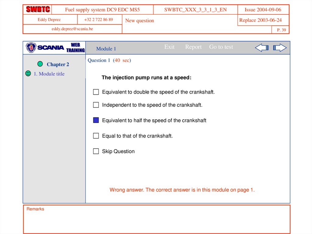
Question 1 (40 sec)
The injection pump runs at a speed:
Equivalent to double the speed of the crankshaft.
Independent to the speed of the crankshaft.
Equivalent to half the speed of the crankshaft
Equal to that of the crankshaft.
Skip Question
Wrong answer. The correct answer is in this module on page 1.
Remarks
40.
Fuel supply system DC9 EDC MS5Eddy Deprez
+32 2 722 86 89
SWBTC_XXX_3_3_1_3_EN
Issue 2004-09-06
Replace 2003-06-24
New question
eddy.deprez@scania.be
P. 40
Module 1
Chapter 2
1. Module title
Exit
Report
Go to test
Question 2 (40 sec)
The rotation of a pump element piston influences:
The time point of injection.
The opening pressure of the injector.
The quantity of fuel injected.
The quantity of fuel allowed into the chamber at the top of the pump
plunger.
Skip Question
Wrong answer. The correct answer is in this module on page 2.
Remarks
41.
Fuel supply system DC9 EDC MS5Eddy Deprez
+32 2 722 86 89
SWBTC_XXX_3_3_1_3_EN
Issue 2004-09-06
Replace 2003-06-24
New question
eddy.deprez@scania.be
P. 41
Module 1
Chapter 2
1. Module title
Exit
Report
Go to test
Question 3 (40 sec)
After injection, when the pressure valve is closed again, pressure
in the delivery pipe:
Increases.
Decreases.
Does not vary.
Skip Question
Wrong answer. The correct answer is in this module on page 4.
Remarks
42.
Fuel supply system DC9 EDC MS5Eddy Deprez
+32 2 722 86 89
SWBTC_XXX_3_3_1_3_EN
Links
Issue 2004-09-06
Replace 2003-06-24
eddy.deprez@scania.be
P. 42
Module 2
estimated time …….
Exit
Report
Go to test
Chapter 2
1.
Module title
2.
Injector and
delivery pipe
This module introduces the
injector and the delivery pipe
Remarks
43.
Fuel supply system DC9 EDC MS5Eddy Deprez
+32 2 722 86 89
eddy.deprez@scania.be
1. Module title
2. Module title
Exit
Issue 2004-09-06
Replace 2003-06-24
Text WSM 03:01-01 page 20
Picture 03_0855
Module 2, page 1
Chapter 2
SWBTC_XXX_3_3_1_3_EN
P. 43
Report
Go to test
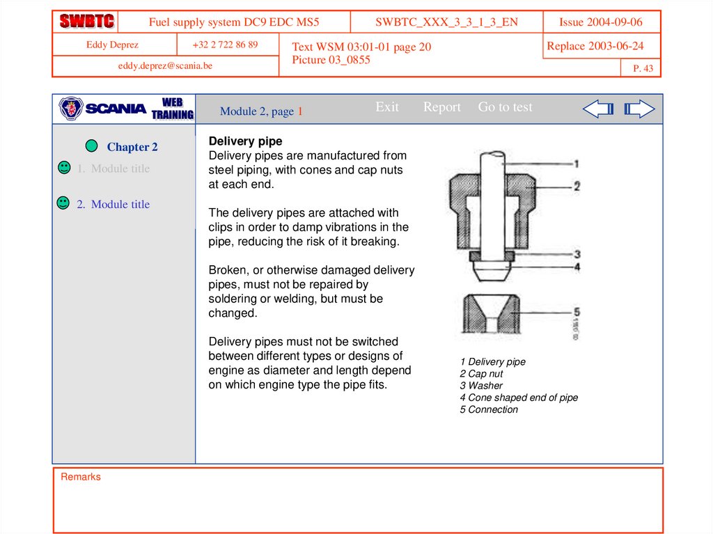
Delivery pipe
Delivery pipes are manufactured from
steel piping, with cones and cap nuts
at each end.
The delivery pipes are attached with
clips in order to damp vibrations in the
pipe, reducing the risk of it breaking.
Broken, or otherwise damaged delivery
pipes, must not be repaired by
soldering or welding, but must be
changed.
Delivery pipes must not be switched
between different types or designs of
engine as diameter and length depend
on which engine type the pipe fits.
Remarks
1 Delivery pipe
2 Cap nut
3 Washer
4 Cone shaped end of pipe
5 Connection
44.
Fuel supply system DC9 EDC MS5Eddy Deprez
+32 2 722 86 89
eddy.deprez@scania.be
1. Module title
2. Module title
Exit
Report
Issue 2004-09-06
Replace 2003-06-24
Text WSM 03:01-01 page 20 modified
Picture 03_0871
Module 2, page 2
Chapter 2
SWBTC_XXX_3_3_1_3_EN
P. 44
Go to test
Injectors
The fuel is forced through the delivery
pipes to the injectors. The injector
atomises the fuel in the combustion
chamber.
The movement of the nozzle needle
is controlled by fuel pressure and
spring force.
When fuel from the injection pump
reaches a certain pressure (opening
pressure), the nozzle needle lifts
(start of injection).
1 Delivery pipe from pump
2 Cap nut
3 Edge filter
4 Leak-off fuel line
5 Spring
6 Nozzle needle
Remarks
45.
Fuel supply system DC9 EDC MS5Eddy Deprez
+32 2 722 86 89
eddy.deprez@scania.be
SWBTC_XXX_3_3_1_3_EN
Replace 2003-06-24
Text WSM 03:01-01 page 20 modified
Picture 03_0871
Module 2, page 3
Exit
Report
Issue 2004-09-06
P. 45
Go to test
Chapter 2
1. Module title
2. Module title
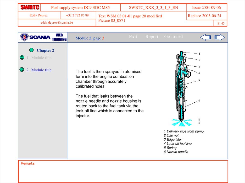
The fuel is then sprayed in atomised
form into the engine combustion
chamber through accurately
calibrated holes.
The fuel that leaks between the
nozzle needle and nozzle housing is
routed back to the fuel tank via the
leak-off line which is connected to the
injector.
1 Delivery pipe from pump
2 Cap nut
3 Edge filter
4 Leak-off fuel line
5 Spring
6 Nozzle needle
Remarks
46.
Fuel supply system DC9 EDC MS5Eddy Deprez
+32 2 722 86 89
SWBTC_XXX_3_3_1_3_EN
Issue 2004-09-06
Replace 2003-06-24
New question
eddy.deprez@scania.be
P. 46
Module 2
Chapter 2
1. Module title
2. Module title
Exit
Report
Go to test
Question 1 (40 sec)
The opening pressure of the injector depends on:
The pressure of the fuel in the tank.
The rotation speed of the engine.
The length of the pipe connecting the injector to the injection pump.
The setting of the spring in the injector.
Skip Question
Wrong answer. The correct answer is in this module on page 2.
Remarks
47.
Fuel supply system DC9 EDC MS5Eddy Deprez
+32 2 722 86 89
SWBTC_XXX_3_3_1_3_EN
Links
Issue 2004-09-06
Replace 2003-06-24
eddy.deprez@scania.be
P. 47
Chapter 2
Exit
Report
Go to test
Chapter 2
1. Module title
2. Module title
In this chapter you learned:
The composition and the operating
principle of the injection pump with its
governor and of the injectors.
The alternating motion of the pump
elements is controlled by the camshaft.
The governor acts on the control rack,
which rotates the pump plungers, and thus
influences the quantity injected.
The injection begins when the pump
plunger closes the inlet and spill ports in
the pump element.
The diameter and the length of the delivery
pipes depend on the type of engine.
Remarks