 Информатика
Похожие презентации:


Increasing Prodictivity thru Cam Templates
1.
Increasing Productivity ThroughCam Templates
Randy Sims
Precision Machine and Manufacturing
500 Industrial Park Road
Grove, Oklahoma 74344
Phone: 918-791-7393
Fax: 918-791-7493
randy.sims@precisionaerogroup.com
http://plmworld.org/
1
2.
Introduction to Precision Aerospace, Inc.Precision Machine and Manufacturing was
established by Tommy Caudill in 1964 as a familyowned and operated business that provides
structural components and subassemblies to a
variety of aerospace and defense prime
contractors.
In 1994, Precision Components Company was
established when Textron Lycoming awarded the
company a sole-source contract to supply cylinder
assemblies for its reciprocating aircraft engines.
Today, the company employs over 200 team
members at its locations in Grove and Owasso,
Oklahoma.
In 2007, the company reorganized and adopted
the name Precision Aerospace, Inc. in order to
more accurately reflect its business focus and
customer base.
2
3.
What are Cam Templates?Cam Templates are nothing more nor less than stored knowledge.
They are very much like Feature Based Machining and Manufacturing Wizards.
Simply put:
Feature Based Machining takes a set of stored rules and applies them to part features to produce
manufacturing operations.
Manufacturing Wizards are set up to guide a programmer through a set series of steps to produce one or
multiple operations.
Cam Templates on the other hand can be used to store operation setup parameters for operation types that
you repeat over and over, such as Cavity Mill operations in which you set specific width and depth of cut
parameters. They can also be used with the File New dialog to work as a “Seed” file to bring in operations,
geometry groups, tools and methods into a manufacturing assembly.
Unlike Feature Based Machining and Manufacturing Wizards, Cam Templates do not require special licensing
or extensive programming skills to create.
3
4.
Why use Cam Templates?Do you find yourself repeating the same operation parameter changes over and over?
Do you have certain cutters that must run on different machines but each machine uses different
radial and or axial cut depths and different feed and speed parameters?
Do you have multiple machines that have different standard tool list?
Do you want to store the Tools and or the associated Methods for various machines and want to
drop them into your current work part at any time?
If so then Cam Templates are your answer!
Yes, there are many ways in Siemens NX to do this, but Cam Templates are one of the simplest
and thus most likely to be utilized methods to access this stored knowledge. When you bring in
an Operation, Tool, or Method from a Cam Template Part your settings are preset so that you or
anyone else who uses this template will get consistent and predictable results.
4
5.
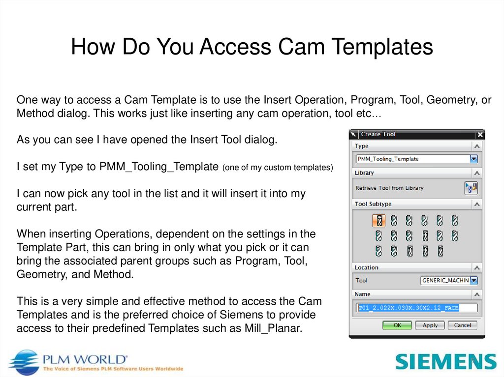
How Do You Access Cam TemplatesOne way to access a Cam Template is to use the Insert Operation, Program, Tool, Geometry, or
Method dialog. This works just like inserting any cam operation, tool etc…
As you can see I have opened the Insert Tool dialog.
I set my Type to PMM_Tooling_Template (one of my custom templates)
I can now pick any tool in the list and it will insert it into my
current part.
When inserting Operations, dependent on the settings in the
Template Part, this can bring in only what you pick or it can
bring the associated parent groups such as Program, Tool,
Geometry, and Method.
This is a very simple and effective method to access the Cam
Templates and is the preferred choice of Siemens to provide
access to their predefined Templates such as Mill_Planar.
5
6.
The second method to access a Cam Template is to use the Insert Operation,Program, Tool, Geometry, or Method dialog again.
Instead of picking Type > mill_planar or mill_contour etc… pick Browse and
navigate to the file you want to read from.
You can then pick from the available items in the template file just like you pick
fixed contour from the mill_contour type.
This is handy when you have numerous Cam Templates and you do not want to
clutter up the Type drop down list excessively.
We use this method to store general operations (such as planar_mill) that have
the same settings that would need to be modified every time if we were to just
use one of the standard operation types.
We also use this to create tool library templates for different machine groups.
6
7.
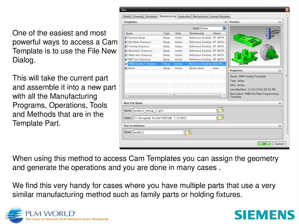
One of the easiest and mostpowerful ways to access a Cam
Template is to use the File New
Dialog.
This will take the current part
and assemble it into a new part
with all the Manufacturing
Programs, Operations, Tools
and Methods that are in the
Template Part.
When using this method to access Cam Templates you can assign the geometry
and generate the operations and you are done in many cases .
We find this very handy for cases where you have multiple parts that use a very
similar manufacturing method such as family parts or holding fixtures.
7
8.
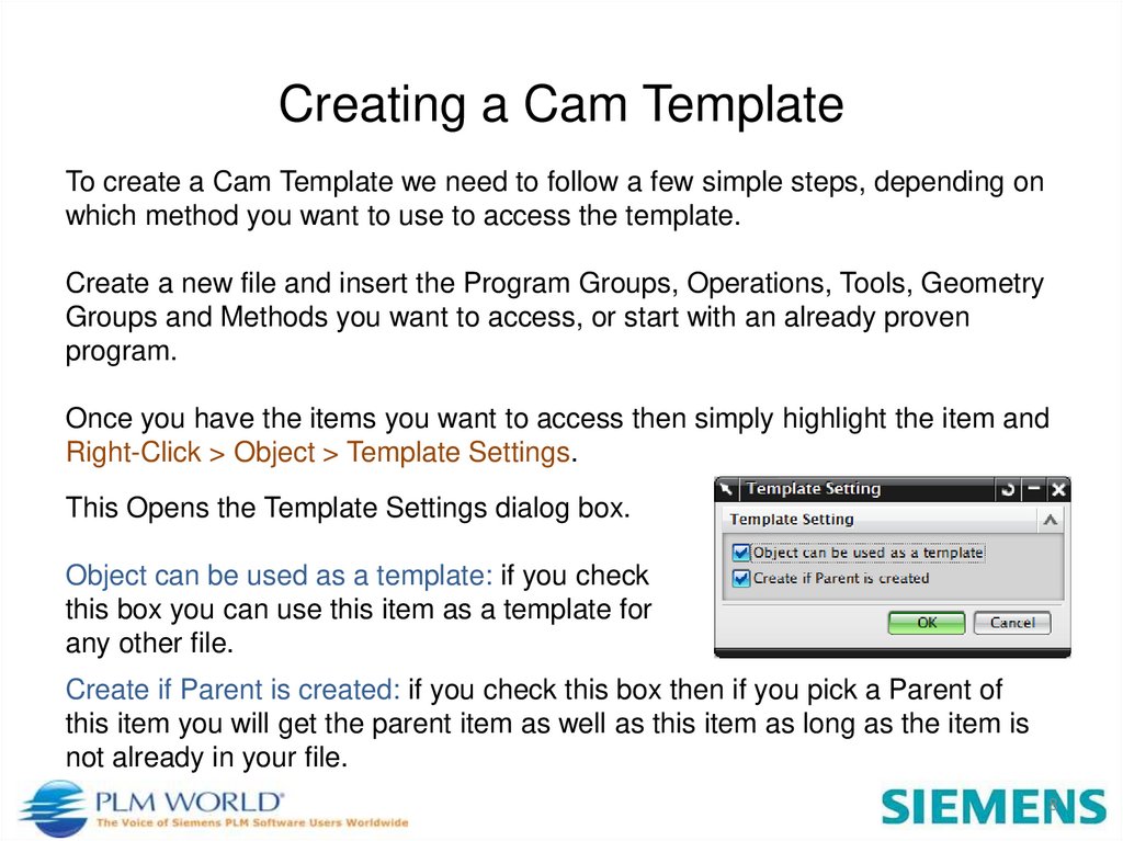
Creating a Cam TemplateTo create a Cam Template we need to follow a few simple steps, depending on
which method you want to use to access the template.
Create a new file and insert the Program Groups, Operations, Tools, Geometry
Groups and Methods you want to access, or start with an already proven
program.
Once you have the items you want to access then simply highlight the item and
Right-Click > Object > Template Settings.
This Opens the Template Settings dialog box.
Object can be used as a template: if you check
this box you can use this item as a template for
any other file.
Create if Parent is created: if you check this box then if you pick a Parent of
this item you will get the parent item as well as this item as long as the item is
not already in your file.
8
9.
Repeat this for all Program, Operations, Tool, Geometry, or Methods that you want to accessfrom other files and save the file to a known directory.
At this point you are ready to use your Cam Template using the “Browse” method described
above.
If instead you want to be able to use the “Type Drop Down” method then you need to do a
couple of other steps.
1) Go to the …/MACH/resource/template_set directory for your site. I place my custom
Templates in the cam_general configuration group but you can use whatever group you
desire. In my case I open the cam_general.opt in a text editor.
2) Add a section to the file such as:
## PMM
${UGII_CAM_TEMPLATE_PART_ENGLISH_DIR}PMM_Tooling_Template.prt
## /PMM
Save the opt file.
This Cam Template will now show up in your dropdown list just like planar_mill.
9
10.
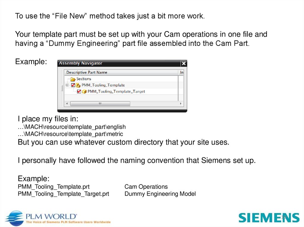
To use the “File New” method takes just a bit more work.Your template part must be set up with your Cam operations in one file and
having a “Dummy Engineering” part file assembled into the Cam Part.
Example:
I place my files in:
…\MACH\resource\template_part\english
…\MACH\resource\template_part\metric
But you can use whatever custom directory that your site uses.
I personally have followed the naming convention that Siemens set up.
Example:
PMM_Tooling_Template.prt
PMM_Tooling_Template_Target.prt
Cam Operations
Dummy Engineering Model
10
11.
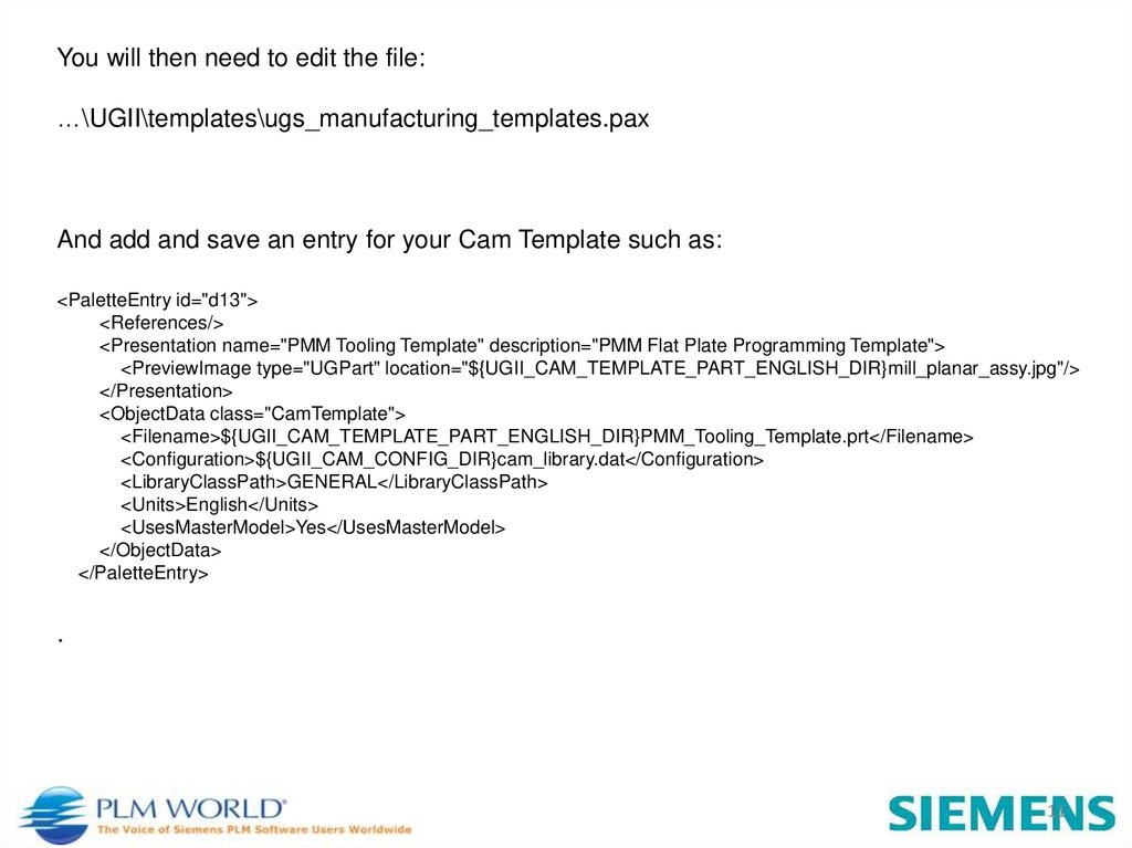
You will then need to edit the file:…\UGII\templates\ugs_manufacturing_templates.pax
And add and save an entry for your Cam Template such as:
<PaletteEntry id="d13">
<References/>
<Presentation name="PMM Tooling Template" description="PMM Flat Plate Programming Template">
<PreviewImage type="UGPart" location="${UGII_CAM_TEMPLATE_PART_ENGLISH_DIR}mill_planar_assy.jpg"/>
</Presentation>
<ObjectData class="CamTemplate">
<Filename>${UGII_CAM_TEMPLATE_PART_ENGLISH_DIR}PMM_Tooling_Template.prt</Filename>
<Configuration>${UGII_CAM_CONFIG_DIR}cam_library.dat</Configuration>
<LibraryClassPath>GENERAL</LibraryClassPath>
<Units>English</Units>
<UsesMasterModel>Yes</UsesMasterModel>
</ObjectData>
</PaletteEntry>
.
11
12.
At this point when you pick File New > Manufacturing Your new Template shouldshow up in the Templates list.
Open an engineering file. Pick File New > Manufacturing and pick your template,
set your file name and directory then pick OK and a new file will open with your
engineering assembled into it and all your template enabled items already defined.
In many cases you only need to assign your geometry and generate your
operations.
What this does is to open a new file and assemble the current part into it and
copy's all the template enabled Program Groups, Operations, Tools, Geometry, and
Methods into the new file. This establishes a manufacturing file that has all the
stored knowledge that you or your company have built into your Cam Template.
This will save you many hours of time while simplifying your job and insuring that
you have consistent and predictable results between programs and programmers.
12
13.
Example NX Session13
14.
Questions?14
15.
Thank You!Siemens PLM Connection 2011
Las Vegas, NV
May 2-5
http://plmworld.org/
15