


 Строительство
Похожие презентации:


")


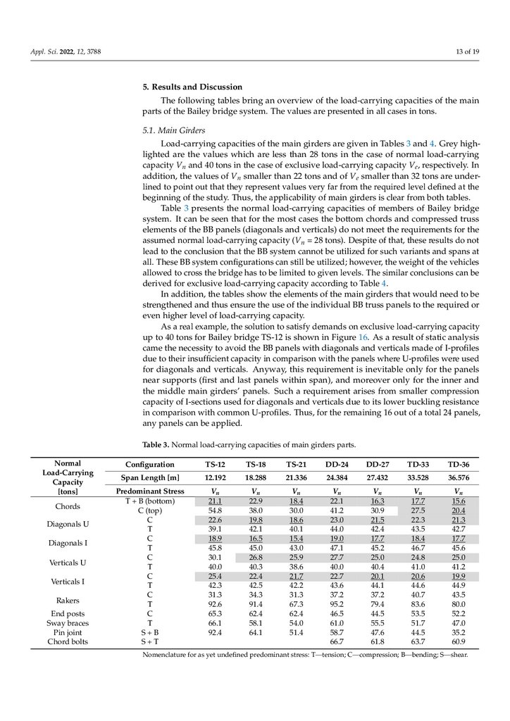
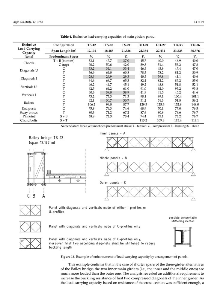
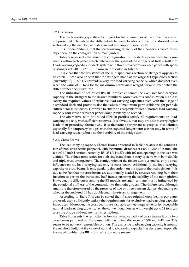
Load-Carrying Capacity of of Bailey Bridge in Civil Applications
1.
appliedsciences
Article
Article
Load-Carrying
in Civil
Civil Applications
Applications
Load‐CarryingCapacity
Capacity of
of Bailey Bridge in
1,
1 , Matúš Farbák
1 and Vladimír Novotný
2
1, Matúš
Jozef
, JaroslavOdrobiňák
Odrobiňák
JozefProkop
Prokop 1,**, Jaroslav
Farbák 1 and Vladimír
Novotný 2
Department
Department of
of Structures
Structures and
andBridges,
Bridges,Faculty
FacultyofofCivil
CivilEngineering,
Engineering,University
UniversityofofŽilina,
Žilina, Univerzitná 8215/1,
Univerzitná
8215/1,
010 26
Žilina, Slovakia; [email protected]
(J.O.);
010 26 Žilina,
Slovakia;
[email protected]
(J.O.); [email protected]
(M.F.)
2
[email protected]
(M.F.) 8, 010 01 Žilina, Slovakia; [email protected]
Tebrico Ltd., P.O. Hviezdoslava
2
Ltd., P.O. Hviezdoslava
8, 010 01 Žilina, Slovakia; [email protected]
* Tebrico
Correspondence:
[email protected]
* Correspondence: [email protected]
11
Abstract: The paper presents an extensive study aimed to determine the applicability of the deAbstract: The paper presents an extensive study aimed to determine the applicability of the de‐
mountable Bailey bridge (BB) system on construction sites or in other temporary conditions while
mountable Bailey bridge (BB) system on construction sites or in other temporary conditions while
meeting the regulations for the design and assessment of steel bridges. The analysis is focused on
meeting the regulations for the design and assessment of steel bridges. The analysis is focused on
whether and to what extent the BB system with spans between 12 and 36 m is usable for on-site
whether and to what extent the BB system with spans between 12 and 36 m is usable for on‐site
freight
lorries with
withaatotal
totalweight
weightofofup
uptoto22–28
22–28tons.
tons.
same
time,
freighttransport
transport with
with conventional
conventional lorries
AtAt
thethe
same
time,
the
BB
system
within
these
spans
should
be
utilized
for
construction
vehicles
with
a
total
weight
the BB system within these spans should be utilized for construction vehicles with a total weight of of
up
capacity,spatial
spatialnumerical
numericalmodels
modelswere
were
analysed
to32–40
32–40tons.
tons. To
To calculate
calculate the
the load-carrying
load‐carrying capacity,
analysed
upto
using
of actual
actual design
design codes
codeswere
wereutilized.
utilized.InInthe
thecase
caseofof
the
main
girders,
using FEM
FEM and
and procedures
procedures of
the
main
girders,
analysis
stabilityof
oftheir
theircompressed
compressedchords.
chords.Recommendations
Recommendations
analysisisis focused
focused on
on the
the out-of-plane
out‐of‐plane stability
forfor
the
use
of
this
bridge
system
in
different
arrangements
of
the
main
girder
and
bridge
deck
are
then
the use of this bridge system in different arrangements of the main girder and bridge deck are then
summarized
and
discussed.
summarized and discussed.
Keywords:
load-carrying capacity;
capacity;stability;
stability;steel
steelbridge;
bridge;temporary
temporarybridge
bridge
Keywords: Bailey
Bailey bridge; load‐carrying
Citation:
Prokop, J.; Odrobiňák, J.;
Farbák,Prokop,
M.; Novotný,
V. ňák, J.;
Citation:
J.; Odrobi
Load‐Carrying Capacity of Bailey
Farbák, M.; Novotný, V.
Bridge in Civil Applications.
Load-Carrying Capacity of Bailey
Appl. Sci. 2022, 12, 3788.
Bridge in Civil Applications. Appl.
https://doi.org/10.3390/app12083788
Sci. 2022, 12, 3788. https://doi.org/
10.3390/app12083788
Academic Editors:
Algirdas Juozapaitis
Academic Editors: Algirdas
and Alfonsas Daniūnas
Juozapaitis and Alfonsas Daniūnas
1.1.Introduction
Introduction
Temporary
developed
forfor
military
purposes
in the
past.
Temporarybridge
bridgestructures
structureswere
weremainly
mainly
developed
military
purposes
in the
Very
they also
to ensure
rapidrapid
access
through
ruralrural
unexplored
areas
[1,2].
past.often,
Very often,
theyserved
also served
to ensure
access
through
unexplored
areas
Increasingly,
originally
militarymilitary
emergency
ones areones
alsoare
used
forused
civil for
purposes
(Figure 1),
[1,2]. Increasingly,
originally
emergency
also
civil purposes
where
their
adaptability,
low
weight,
but
especially
extremely
fast
erection
and
(Figure 1), where their adaptability, low weight, but especially extremely fast erectionalmost
and
immediate
usabilityusability
for traffic
utilized.
almost immediate
forare
traffic
are utilized.
Received: 1 March 2022
Received: 1 March 2022
Accepted: 5 April 2022
Accepted: 5 April 2022
Published: 8 April 2022
Published: 8 April 2022
Publisher’s Note: MDPI stays neu‐
Publisher’s Note: MDPI stays neutral
tral with regard to jurisdictional
with
regard
to jurisdictional
claims
in
claims
in published
maps and
institu‐
published
maps and institutional affiltional affiliations.
iations.
Copyright: © 2022 by the authors. Li‐
Copyright:
© 2022
by the
authors.
censee MDPI,
Basel,
Switzerland.
Licensee
MDPI,
Basel,
This article
is an
open Switzerland.
access article
This
article isunder
an open
accessand
article
distributed
the terms
con‐
distributed
under
the Commons
terms and
ditions of the
Creative
At‐
tribution of
(CC
BY)
license (https://cre‐
conditions
the
Creative
Commons
ativecommons.org/licenses/by/4.0/).
Attribution
(CC BY) license (https://
creativecommons.org/licenses/by/
4.0/).
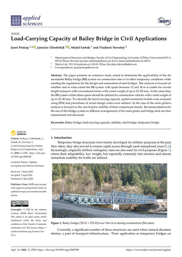
Figure 1. Bailey bridge (TS‐12 + TD‐33) over Vah river during construction (Slovakia).
Figure 1. Bailey bridge (TS-12 + TD-33) over Vah river during construction (Slovakia).
Currently, a significant number of these structures are used when natural disasters
destroy a part of transport infrastructure. Their application as temporary bridges on
Appl. Sci. 2022, 12, 3788. https://doi.org/10.3390/app12083788
Appl. Sci. 2022, 12, 3788. https://doi.org/10.3390/app12083788
www.mdpi.com/journal/applsci
https://www.mdpi.com/journal/applsci
2.
Appl. Sci. 2022, 12, 3788Appl. Sci. 2022, 12, 3788
Appl. Sci. 2022, 12, 3788
2 of 20
2 of 20
2 of 19
Currently, a significant number of these structures are used when natural disasters
Currently,
significant
number of these
when bridges
natural on
disasters
destroy
a part of atransport
infrastructure.
Theirstructures
applicationare
as used
temporary
larger
destroy
a
part
of
transport
infrastructure.
Their
application
as
temporary
bridges
on
larger
construction
also growing
2). In addition,
they
areasused
aslarger
‘shortconstruction
sites issites
alsoisgrowing
(Figure(Figure
2). In addition,
they are
used
‘short‐term’
construction
sites
is also growing
(Figure
2). and
In addition,
they
used as
‘short‐term’
term’
temporary
(semi-permanent)
bridges
on
local
and or
rural
or are
unpaved
roads
when
the
temporary
(semi‐permanent)
bridges
on local
rural
unpaved
roads
when
the
con‐
temporary
bridges
local
andinefficient
ruralinefficient
or unpaved
roads
when
the
con‐to
construction
a permanent
bridge
still
financially
not possible
due
struction
of (semi‐permanent)
aofpermanent
bridge
is stillison
financially
or not or
possible
due to
traffic
struction
of (Figure
a permanent
traffic
issues
issues
(Figure
3). 3). bridge is still financially inefficient or not possible due to traffic
issues (Figure 3).
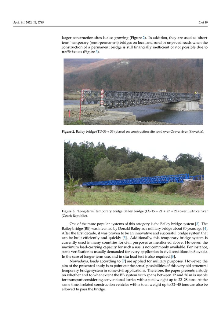
Figure 2. Bailey bridge (TD‐36 + 36) placed on construction site road over Orava river (Slovakia).
Figure
site road
road over
overOrava
Oravariver
river(Slovakia).
(Slovakia).
Figure2.2.Bailey
Baileybridge
bridge(TD-36
(TD‐36++ 36)
36) placed
placed on
on construction
construction site
Figure 3. ‘Long‐term’ temporary bridge Bailey bridge (DS‐15 + 21 + 27 + 21) over Lužnice river
Figure3.Republic).
3.‘Long-term’
‘Long‐term’ temporary
temporary bridge
bridge Bailey
Bailey bridge
bridge (DS‐15
(Czech
Figure
(DS-15 ++ 21
21 ++ 27
27 ++21)
21)over
overLužnice
Lužniceriver
river
(Czech Republic).
(Czech Republic).
One of the more popular systems of this category is the Bailey bridge system [3]. The
One
the
more
popular
systems
of this
this
category
bridge
system
[3].
The
One
ofofthe
more
popular
systems
of
category
is the
the Bailey
Bailey
bridge
system
[3].ago
The
Bailey
bridge
(BB)
was
invented
by Donald
Bailey
as a is
military
bridge
about
80 years
Bailey
bridge
(BB)
was
invented
by
Donald
Bailey
as
a
military
bridge
about
80
years
ago
Bailey
bridge
invented
Donald
as a military
bridge
about bridge
80 years
ago
[4].
[4]. After
the(BB)
first was
decade,
it wasby
proven
to Bailey
be an innovative
and
successful
system
[4]. After
firstefficiently
decade,
itand
wasquickly
proven
toanbe
an innovative
successful
bridge
system
After
the first
decade,
it was
proven
to be
innovative
and
successful
bridge
system
that
that
can
bethe
built
[5].
Additionally,
thisand
temporary
bridge
system
is
thatbecan
be
built
and
quickly
[5].
Additionally,
thistemporary
temporary
bridge
system
isis
can
built
efficiently
quickly
Additionally,
this
bridge
system
currently
used
inefficiently
manyand
countries
for[5].
civil
purposes
as mentioned
above.
However,
the
currently
used
in
many
countries
for
civil
purposes
as
mentioned
above.
However,
the
currently
used
in many countries
forsuch
civilapurposes
mentioned
above. For
However,
the
maximum
load‐carrying
capacity for
use is notas
commonly
available.
instance,
maximum
load‐carrying
capacity
for
such
a
use
is
not
commonly
available.
For
instance,
maximum
load-carrying
capacity
for
such
a
use
is
not
commonly
available.
For
instance,
static verification is usually demanded for every application in civil conditions in Slo‐
staticverification
verification
usually
demanded
every
application
in
civil
conditions
in Slo‐
static
usually
demanded
forfor
every
application
in civil
conditions
vakia.
In the caseisofis
longer
term
use, and
in
situ
load
test is also
required
[6]. in Slovakia.
vakia.
In
the
case
of
longer
term
use,
and
in
situ
load
test
is
also
required
[6].
In theNowadays,
case of longer
term
use, andtoin[7]
situ
load
test isfor
also
required
[6].
loads
according
are
applied
military
purposes.
However, the
loads
according
to [7]
[7]
are
applied
for military
militaryofpurposes.
However,
the
loads
according
to
for
purposes.
However,
the
aimNowadays,
ofNowadays,
the presented
study
is to point
outare
theapplied
actual possibilities
this very old
structural
aim
of
the
presented
study
is
to
point
out
the
actual
possibilities
of
this
very
old
structural
temporary
bridge system
civilout
applications.
the
presents
a study
aim
of the presented
studyinissome
to point
the actual Therefore,
possibilities
ofpaper
this very
old structural
temporary
bridge
system
insome
some
civil
applications.
Therefore,
the
on
whether
and tosystem
what extent
thecivil
BB applications.
system
with spans
between
12
andpresents
36 m is ausable
temporary
bridge
in
Therefore,
thepaper
paper
presents
astudy
study
on
whether
and
to
what
extent
the
BB
system
with
spans
between
12
and
36
m
is
usable
forwhether
transport
considering
conventional
lorries with
total weight
up 12
to 22–28
the
on
and
to what extent
the BB system
withaspans
between
and 36tons.
m isAt
usable
fortransport
transportconsidering
consideringconventional
conventional lorries
lorries with
with aa total
for
total weight
weight up
up to
to22–28
22–28tons.
tons.At
Atthe
the
same time, isolated construction vehicles with a total weight up to 32–40 tons can also be
allowed to pass the bridge.
3.
Appl. Sci. 2022, 12, 37883 of 19
2. Outline of the Study
For the purposes of the analysis, the load-carrying capacity of individual bridge
members was selected as a decisive criterion for the applicability of the BB system. Based
on experience, double-truss and triple-truss main girders were taken into account as singlestory and double-story alternatives:
Double-truss, single-story (DS) for a span with length of 12.196 m;
Triple-truss, single-story (TS) for spans: 12.192 m, 15.240 m, 18.288 m and 21.336 m;
Double-truss, double-story (DD) for spans: 21.336 m, 24.384 m and 27.432 m;
Triple-truss, double-story (TD) for spans: 27.432 m, 30.480 m, 33.528 m, and 36.576 m.
In Table 1, the seven chosen variants are presented, which were identified as most
suitable and applicable after evaluating several alternatives.
Table 1. Spans and BB arrangement of the chosen alternatives.
Span
Truss
Story
Abbreviation
40 ft/12.192 m
60 ft/18.288 m
70 ft/21.336 m
80 ft/24.384 m
90 ft/27.432 m
110 ft/33.528 m
120 ft/36.576 m
triple
triple
triple
double
double
triple
triple
single
single
single
double
double
double
double
TS-12
TS-18
TS-21
DD-24
DD-27
TD-33
TD-36
All bridges are supposed to act as simply supported, while the end verticals of BB are
present on both ends of main girders. It is further assumed that standardized bearings of
the BB system are used to transfer reactions from the superstructures to substructures.
With respect to the structural arrangement of the BB system [3], the load-carrying
capacities were derived from the resistance of following members or their cross-sections
(the terminology of Bailey bridge from [3] is given in single quotation marks, if differ from
the common bridge engineering terminology):
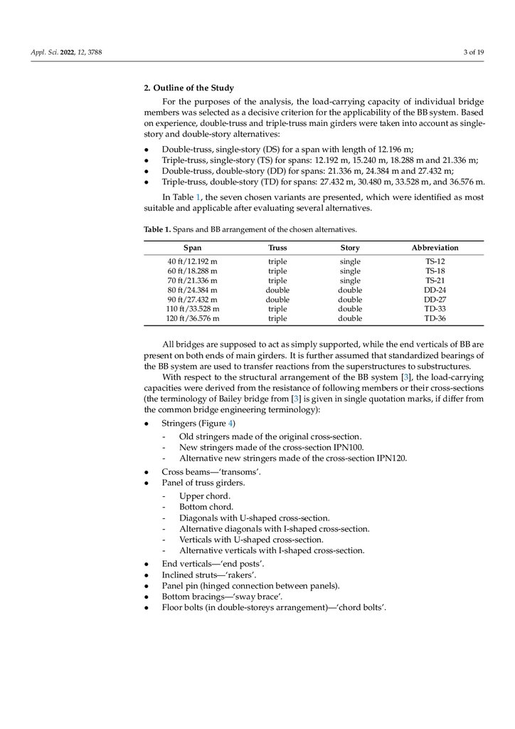
Stringers (Figure 4)
-
Cross beams—‘transoms’.
Panel of truss girders.
-
Old stringers made of the original cross-section.
New stringers made of the cross-section IPN100.
Alternative new stringers made of the cross-section IPN120.
Upper chord.
Bottom chord.
Diagonals with U-shaped cross-section.
Alternative diagonals with I-shaped cross-section.
Verticals with U-shaped cross-section.
Alternative verticals with I-shaped cross-section.
End verticals—‘end posts’.
Inclined struts—‘rakers’.
Panel pin (hinged connection between panels).
Bottom bracings—‘sway brace’.
Floor bolts (in double-storeys arrangement)—‘chord bolts’.
4.
Appl. Sci. 2022, 12, 3788Appl. Sci. 2022, 12, 3788
Appl. Sci. 2022, 12, 3788
4 of 19
4 of 20
4 of 20
Figure 4.
4. Scheme of
three‐stringer panel.
Figure
panel.
Figure 4.Scheme
Scheme of
of three-stringer
three‐stringer panel.
load‐carrying
two
variants
of
the
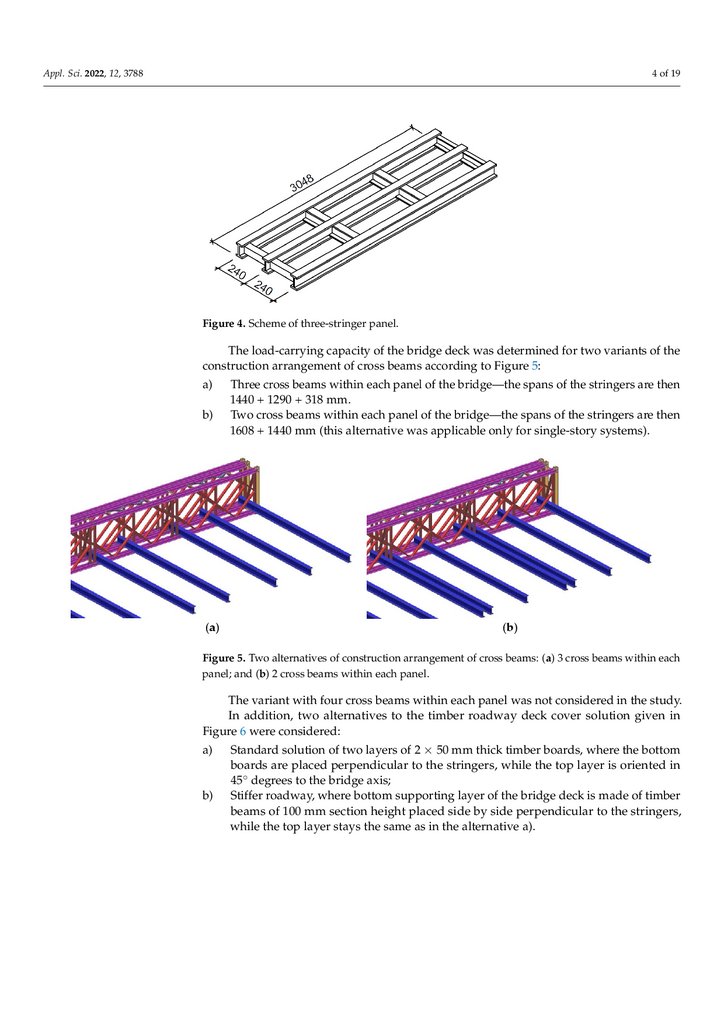
The
capacity
ofthe
thebridge
bridgedeck
deckwas
wasdetermined
determinedfor
for
two
variants
the
Theload-carrying
load‐carryingcapacity
capacityof
of
the
bridge
deck
was
determined
for
two
variants
ofof
the
construction
arrangement
of
cross
beams
according
to
Figure
5:
construction
arrangement
of
cross
beams
according
to
Figure
5:
construction arrangement of cross beams according to Figure 5:
a)
beams
within
each
panel
the
bridge—the
spans
stringers
a)
bridge—the
spans
ofof
thethe
stringers
areare
then
a) Three
Three cross
crossbeams
beamswithin
withineach
eachpanel
panelofof
ofthe
the
bridge—the
spans
of
the
stringers
are
then
1440
+
1290
+
318
mm.
1440
+
1290
+
318
mm.
then 1440 + 1290 + 318 mm.
b)
Two
the
stringers
are
then
b)
beams
within
eachpanel
panelof
ofthe
thebridge—the
bridge—thespans
spansof
the
stringers
are
then
b) Twocross
crossbeams
beamswithin
withineach
each
panel
of
the
bridge—the
spans
ofof
the
stringers
are
then
1608
+
1440
mm
(this
alternative
was
applicable
only
for
single‐story
systems).
+
1440
mm
(this
alternative
was
applicable
only
for
single-story
systems).
1608 + 1440 mm (this alternative was applicable only for single‐story systems).
(a)
(a)
(b)
(b)
Figure 5. Two alternatives of construction arrangement of cross beams: (a) 3 cross beams within
Figure 5. Two alternatives of construction arrangement of cross beams: (a) 3 cross beams within
each panel;
and
(b) 2 cross of
beams
within each
panel.
Figure
5. Two
alternatives
construction
arrangement
each panel;
and
(b) 2 cross beams
within each
panel. of cross beams: (a) 3 cross beams within each
panel; and (b) 2 cross beams within each panel.
The
Thevariant
variantwith
withfour
fourcross
crossbeams
beamswithin
withineach
eachpanel
panelwas
wasnot
notconsidered
consideredin
inthe
thestudy.
study.
The
variant
with
four
cross
beams
within
each
panel
was
not
considered
in
study.
In
addition,
two
alternatives
to
the
timber
roadway
deck
cover
solution
given
Figure
In addition, two alternatives to the timber roadway deck cover solution givenin
inthe
Figure
In
addition,
two
alternatives
to
the
timber
roadway
deck
cover
solution
given
in
66were
considered:
were considered:
Figure
6 were considered:
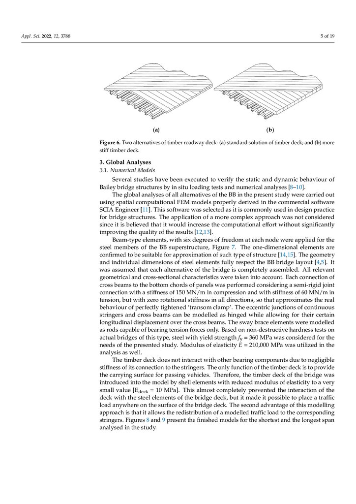
a)
a) Standard
Standard solution
solution of
of two
twolayers
layers of
of 22×× 50
50 mm
mmthick
thicktimber
timber boards,
boards,where
where the
the bottom
bottom
are
placed
perpendicular
to
the
stringers,
while
the
top
layer
is
oriented
45°
a) boards
Standard
solution
of
two
layers
of
2
×
50
mm
thick
timber
boards,
where
thein
bottom
boards are placed perpendicular to the stringers, while the top layer is oriented
in
45°
degrees
to
the
bridge
axis;
boards
are
placed
perpendicular
to
the
stringers,
while
the
top
layer
is
oriented
in
degrees
to the bridge axis;
◦ degrees
b)
Stiffer
roadway,
where
bottom
supporting
layer
of
the
bridge
deck
is
made
of
timber
45
to
the
bridge
axis;
b) Stiffer roadway, where bottom supporting layer of the bridge deck is made of timber
of
section
height
placed
by
perpendicular
the
b) beams
Stiffer
where
bottom
supporting
layer
of the
bridge deck to
is
of timber
beamsroadway,
of 100
100 mm
mm
section
height
placed side
side
by side
side
perpendicular
to made
the stringers,
stringers,
while
the
top
layer
stays
the
same
as
in
the
alternative
a).
beams
of
100
mm
section
height
placed
side
by
side
perpendicular
to
the
stringers,
while the top layer stays the same as in the alternative a).
while the top layer stays the same as in the alternative a).
5.
Appl. Sci. 2022, 12, 3788Appl. Sci. 2022, 12, 3788
5 of 20
5 of 19
(a)
(b)
Figure 6.
6. Two
Two alternatives
alternatives of
oftimber
timberroadway
roadwaydeck:
deck:(a)
(a)standard
standardsolution
solution
timber
deck;
and
Figure
ofof
timber
deck;
and
(b)(b)
more
more stiff timber deck.
stiff timber deck.
3. Global
Global Analyses
Analyses
3.1. Numerical
NumericalModels
Models
Several
behaviour
of of
Several studies
studies have
havebeen
beenexecuted
executedtotoverify
verifythe
thestatic
staticand
anddynamic
dynamic
behaviour
[8–10].
Bailey bridge
bridge structures
structuresby
byin
insitu
situloading
loadingtests
testsand
andnumerical
numericalanalyses
analyses
[8–10].
The
the
present
study
were
carried
outout
The global
global analyses
analysesof
ofall
allalternatives
alternativesofofthe
theBB
BBinin
the
present
study
were
carried
using
inin
the
commercial
software
using spatial
spatial computational
computationalFEM
FEMmodels
modelsproperly
properlyderived
derived
the
commercial
software
used
in in
design
practice
SCIA Engineer
Engineer [11].
[11].This
Thissoftware
softwarewas
wasselected
selectedasasit itisiscommonly
commonly
used
design
practice
was
notnot
considered
for bridge
bridge structures.
structures. The
Theapplication
applicationofofa amore
morecomplex
complexapproach
approach
was
considered
since it is
effort
without
significantly
is believed
believed that
thatititwould
wouldincrease
increasethe
thecomputational
computational
effort
without
significantly
improving
improving the
the quality
qualityof
ofthe
theresults
results[12,13].
[12,13].
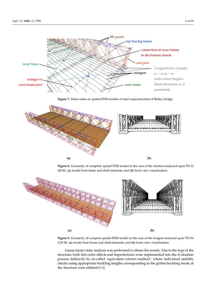
Beam‐type
atat
each
node
were
applied
forfor
thethe
Beam-typeelements,
elements,with
withsix
sixdegrees
degreesofoffreedom
freedom
each
node
were
applied
steel members
of
the
BB
superstructure,
Figure
7.
The
one‐dimensional
elements
are
con‐
members of the BB superstructure, Figure 7. The one-dimensional elements are
firmed to be
for for
approximation
of such
type
of structure
[14,15].
TheThe
geometry
confirmed
to suitable
be suitable
approximation
of such
type
of structure
[14,15].
geometry
and individual
dimensions
of
steel
elements
fully
respect
the
BB
bridge
layout
[4,5].
was It
individual dimensions of steel elements fully respect the BB bridge layoutIt[4,5].
assumed
that each
of the bridge
completely
assembled.
All relevantAll
geomet‐
was
assumed
thatalternative
each alternative
of theisbridge
is completely
assembled.
relevant
rical and cross‐sectional
characteristics
were taken
account.
Each connection
of cross of
geometrical
and cross-sectional
characteristics
wereinto
taken
into account.
Each connection
beamsbeams
to the to
bottom
chordschords
of panels
was performed
considering
a semi‐rigid
joint con‐
cross
the bottom
of panels
was performed
considering
a semi-rigid
joint
nection with
a stiffness
of 150
MN/m
in compression
andand
with
stiffness
of of
60 60
MN/m
in in
connection
with
a stiffness
of 150
MN/m
in compression
with
stiffness
MN/m
tension, but
that
approximates
thethe
real
tension,
but with
with zero
zerorotational
rotationalstiffness
stiffnessininallalldirections,
directions,soso
that
approximates
real
behaviour
of
perfectly
tightened
‘transom
clamp’.
The
eccentric
junctions
of
continuous
behaviour of perfectly tightened ‘transom clamp’. The eccentric junctions of continuous
stringers and
can
be be
modelled
as hinged
whilewhile
allowing
for their
lon‐
stringers
andcross
crossbeams
beams
can
modelled
as hinged
allowing
forcertain
their certain
gitudinal
displacement
over
the
cross
beams.
The
sway
brace
elements
were
modelled
as
longitudinal displacement over the cross beams. The sway brace elements were modelled
rods
capable
of
bearing
tension
forces
only.
Based
on
non‐destructive
hardness
tests
on
as rods capable of bearing tension forces only. Based on non-destructive hardness tests on
360
MPa
was
considered
forfor
thethe
actual bridges
actual
bridges of
of this
thistype,
type,steel
steelwith
withyield
yieldstrength
strengthfy f=y =
360
MPa
was
considered
needs of
MPa
was
utilized
in in
thethe
needs
of the
the presented
presentedstudy.
study.Modulus
Modulusofofelasticity
elasticityE E= =210,000
210,000
MPa
was
utilized
analysis as
analysis
as well.
well.
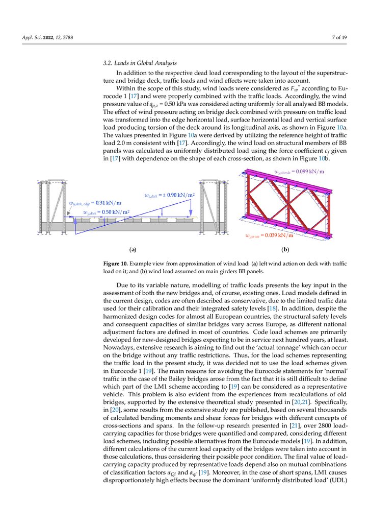
The timber deck does not interact with other bearing components due to negligible
stiffness of its connection to the stringers. The only function of the timber deck is to provide
the carrying surface for passing vehicles. Therefore, the timber deck of the bridge was
introduced into the model by shell elements with reduced modulus of elasticity to a very
small value [Edeck = 10 MPa]. This almost completely prevented the interaction of the
deck with the steel elements of the bridge deck, but it made it possible to place a traffic
load anywhere on the surface of the bridge deck. The second advantage of this modelling
approach is that it allows the redistribution of a modelled traffic load to the corresponding
stringers. Figures 8 and 9 present the finished models for the shortest and the longest span
analysed in the study.
6.
top bracing frameconnection of cross beams
to the bottom chords
Appl. Sci. 2022, 12, 3788
Appl. Sci. 2022, 12, 3788
6 of 19
6 of 20
end post
sway brace
3 supports for 3 panels
BB panels
stringer to
cross beam joint
stringers
uz + uz/uy + uz
top bracing frame (side where longitu‐
dinal movement ux is
cross beam
connection
of cross beams
permitted)
to the bottom chords
Figure 7. Some notes on spatial FEM models of steel superstructure of Bailey bridge.
sway brace
stringer to
cross beam joint
end post
The timber deck does not interact with other bearing components due to negligible stiff‐
3 supports
3 panels
ness of its connection to the stringers. The only function of the timber
deck is tofor
provide
the
stringers
+ uz/uywas
+ uintroduced
z
uzbridge
carrying surface for passing vehicles. Therefore, the timber
deck of the
into the model by shell elements with reduced modulus of elasticity to(side
a very
smalllongitu‐
value [Edeck
where
= 10 MPa]. This almost completely prevented the interaction of the deck with the steel ele‐
dinal movement ux is
beam
ments of the bridge deck, but it made it possiblecross
to place
a traffic load anywhere on the surface
permitted)
of the bridge deck. The second advantage of this modelling approach
is that it allows the re‐
distribution of a modelled traffic load to the corresponding stringers. Figures 8 and 9 present
Figure 7. Some notes on spatial FEM models of steel superstructure of Bailey bridge.
the finished
forspatial
the shortest
and theof
longest
span analysedof
inBailey
the study.
Figure
7. Somemodels
notes on
FEM models
steel superstructure
bridge.
The timber deck does not interact with other bearing components due to negligible stiff‐
ness of its connection to the stringers. The only function of the timber deck is to provide the
carrying surface for passing vehicles. Therefore, the timber deck of the bridge was introduced
into the model by shell elements with reduced modulus of elasticity to a very small value [Edeck
= 10 MPa]. This almost completely prevented the interaction of the deck with the steel ele‐
ments of the bridge deck, but it made it possible to place a traffic load anywhere on the surface
of the bridge deck. The second advantage of this modelling approach is that it allows the re‐
distribution of a modelled traffic load to the corresponding stringers. Figures 8 and 9 present
the finished models for the shortest and the longest span analysed in the study.
(a)
Appl. Sci. 2022, 12, 3788
(b)
Figure 8. Geometry of complete spatial FEM model in the case of the shortest analysed span TS‐12
7 of 20
Figure 8. Geometry of complete spatial FEM model in the case of the shortest analysed span
TS-12
(40 ft): (a) model from beam and shell elements; and (b) front view visualization.
(40 ft): (a) model from beam and shell elements; and (b) front view visualization.
(a)
(b)
Figure 8. Geometry of complete spatial FEM model in the case of the shortest analysed span TS‐12
(40 ft): (a) model from beam and shell elements; and (b) front view visualization.
(a)
(b)
Figure 9. Geometry of compete spatial FEM model in the case of the longest analysed span TD‐36
Figure 9. Geometry of compete spatial FEM model in the case of the longest analysed span TD-36
(120 ft): (a) model from beam and shell elements; and (b) front view visualization.
(120 ft): (a) model from beam and shell elements; and (b) front view visualization.
Linear elastic static analysis was performed to obtain the results. Due to the type of
Linear elastic static analysis was performed to obtain the results. Due to the type of the
the structure, both 2nd order effects and imperfections were implemented into the evalu‐
structure,
both 2nd order effects and imperfections were implemented into the evaluation
ation process indirectly by so‐called ‘equivalent column method’, where individual sta‐
process
indirectly
byappropriate
so-called ‘equivalent
column
method’, where
stability
bility checks using
buckling lengths
corresponding
to theindividual
global buckling
checks
using
appropriate
buckling
lengths
corresponding
to
the
global
buckling
mode
of
mode of the structure were utilized [16].
the structure were utilized [16].
3.2. Loads in Global Analysis
In addition to the respective dead load corresponding to the layout of the superstruc‐
ture and bridge deck, traffic loads and wind effects were taken into account.
Within the scope of this study, wind loads were considered as Fw* according to Euro‐
code 1 [17] and were properly combined with the traffic loads. Accordingly, the wind pres‐
7.
Figure 9. Geometry of compete spatial FEM model in the case of the longest analysed span TD‐36(120 ft): (a) model from beam and shell elements; and (b) front view visualization.
Appl. Sci. 2022, 12, 3788
Linear elastic static analysis was performed to obtain the results. Due to the type of
the structure, both 2nd order effects and imperfections were implemented into the evalu‐
ation process indirectly by so‐called ‘equivalent column method’, where individual sta‐
7 of 19
bility checks using appropriate buckling lengths corresponding to the global buckling
mode of the structure were utilized [16].
3.2.
3.2.Loads
LoadsininGlobal
GlobalAnalysis
Analysis
InInaddition
deadload
loadcorresponding
corresponding
layout
of the
superstrucadditionto
tothe
the respective
respective dead
to to
thethe
layout
of the
superstruc‐
ture
and wind
windeffects
effectswere
weretaken
takeninto
into
account.
tureand
andbridge
bridgedeck,
deck,traffic
traffic loads
loads and
account.
Within
thisstudy,
study,wind
windloads
loads
were
considered
Fw * according
to EuWithinthe
thescope
scope of this
were
considered
as Fas
w* according
to Euro‐
code 11[17]
were
properly
combined
with with
the traffic
loads. Accordingly,
the windthe
pres‐
rocode
[17]and
and
were
properly
combined
the traffic
loads. Accordingly,
wind
sure value
of qof
p,z =
0.50
actingacting
uniformly
for all analysed
BB models.
The
pressure
value
qp,z
= kPa
0.50was
kPaconsidered
was considered
uniformly
for all analysed
BB models.
effect
of wind
pressure
acting
on bridge
deck combined
with pressure
on traffic
wasload
The
effect
of wind
pressure
acting
on bridge
deck combined
with pressure
onload
traffic
transformed
intointo
the edge
horizontal
load, load,
surface
horizontal
load and
vertical
surface load
was
transformed
the edge
horizontal
surface
horizontal
load
and vertical
surface
producing
torsion
of
the
deck
around
its
longitudinal
axis,
as
shown
in
Figure
10a.
The
val‐
load producing torsion of the deck around its longitudinal axis, as shown in Figure 10a.
uesvalues
presented
in Figure
10a were
by utilizing
the reference
height ofheight
trafficof
load
The
presented
in Figure
10aderived
were derived
by utilizing
the reference
traffic
2.0
m
consistent
with
[17].
Accordingly,
the
wind
load
on
structural
members
of
BB
panels
load 2.0 m consistent with [17]. Accordingly, the wind load on structural members of BB
was calculated
as uniformly
distributed
load using
theusing
force the
coefficient
cf given inc[17]
panels
was calculated
as uniformly
distributed
load
force coefficient
f given
with
dependence
on
the
shape
of
each
cross‐section,
as
shown
in
Figure
10b.
in [17] with dependence on the shape of each cross-section, as shown in Figure 10b.
wy,chords = 0.099 kN/m
wz,deck = ± 0.90 kN/m2
wy,deck, edge = 0.31 kN/m
wy,deck = 0.50 kN/m2
wy,truss = 0.039 kN/m
(a)
(b)
Figure 10. Example view from approximation of wind load: (a) left wind action on deck with traffic
Figure 10. Example view from approximation of wind load: (a) left wind action on deck with traffic
load on it; and (b) wind load assumed on main girders BB panels.
load on it; and (b) wind load assumed on main girders BB panels.
Due to its variable nature, modelling of traffic loads presents the key input in the
Due to its variable nature, modelling of traffic loads presents the key input in the
assessment of both the new bridges and, of course, existing ones. Load models defined in
assessment of both the new bridges and, of course, existing ones. Load models defined in
the current design, codes are often described as conservative, due to the limited traffic
the current design, codes are often described as conservative, due to the limited traffic data
used for their calibration and their integrated safety levels [18]. In addition, despite the
harmonized design codes for almost all European countries, the structural safety levels
and consequent capacities of similar bridges vary across Europe, as different national
adjustment factors are defined in most of countries. Code load schemes are primarily
developed for new-designed bridges expecting to be in service next hundred years, at least.
Nowadays, extensive research is aiming to find out the ‘actual tonnage’ which can occur
on the bridge without any traffic restrictions. Thus, for the load schemes representing
the traffic load in the present study, it was decided not to use the load schemes given
in Eurocode 1 [19]. The main reasons for avoiding the Eurocode statements for ‘normal’
traffic in the case of the Bailey bridges arose from the fact that it is still difficult to define
which part of the LM1 scheme according to [19] can be considered as a representative
vehicle. This problem is also evident from the experiences from recalculations of old
bridges, supported by the extensive theoretical study presented in [20,21]. Specifically,
in [20], some results from the extensive study are published, based on several thousands
of calculated bending moments and shear forces for bridges with different concepts of
cross-sections and spans. In the follow-up research presented in [21], over 2800 loadcarrying capacities for those bridges were quantified and compared, considering different
load schemes, including possible alternatives from the Eurocode models [19]. In addition,
different calculations of the current load capacity of the bridges were taken into account in
those calculations, thus considering their possible poor condition. The final value of loadcarrying capacity produced by representative loads depend also on mutual combinations
of classification factors αQi and αqi [19]. Moreover, in the case of short spans, LM1 causes
disproportionately high effects because the dominant ‘uniformly distributed load’ (UDL)
8.
Appl. Sci. 2022, 12, 3788Appl. Sci. 2022, 12, 3788
8 of 19
as well as the dominant ‘tandem system’ (TS) are concentrated together in the same lane on
the relatively small length section. The abovementioned phenomenon is even more visible
in narrow bridges. Findings that the load schemes given in the Eurocode [19] are not very
suitable for load-carrying capacity calculations of existing bridges are also supported by
the conclusions in [22], which provides an extensive state of the art presentation of the
traffic load models.
Thus, the schemes shown in Figures 11 and 12 were taken into account. These schemes
come from the former Slovak national code and were slightly modified for the purpose
of narrow bridges. These load schemes, utilized for several decades, reflect more to the
traffic situations in narrow bridges [21], especially, when the load-carrying capacity of the
bridge will be probably limited by the elements of member steel deck. Another advantage
is that the required vehicle weight, which represents the instantaneous permissible weight
of vehicle passing the bridge, is relatively clearly defined therein [20,21].
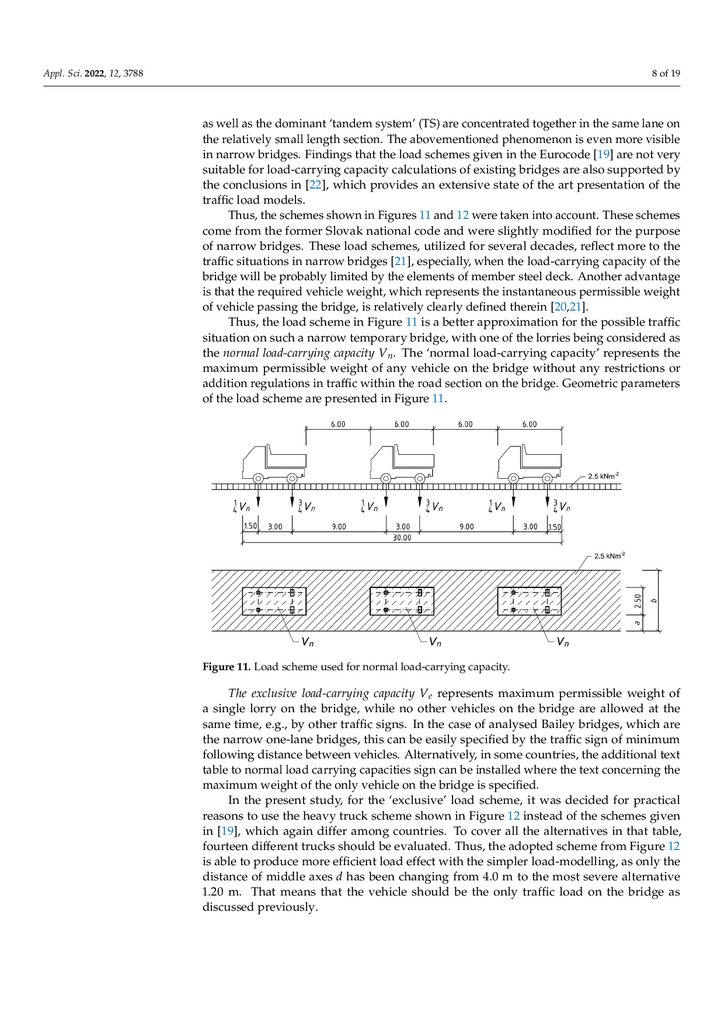
Thus, the load scheme in Figure 11 is a better approximation for the possible traffic
situation on such a narrow temporary bridge, with one of the lorries being considered as
the normal load-carrying capacity Vn . The ‘normal load-carrying capacity’ represents the
maximum permissible weight of any vehicle on the bridge without any restrictions or
9 of 20
addition regulations in traffic within the road section on the bridge. Geometric parameters
of the load scheme are presented in Figure 11.
Figure11.
11.Load
Loadscheme
scheme used
used for
for normal load-carrying
load‐carrying capacity.
Figure
capacity.
Theexclusive
exclusive load-carrying
load‐carrying capacity
permissible
weight
of aof
The
capacity VVe erepresents
representsmaximum
maximum
permissible
weight
thethe
bridge,
while
no other
vehicles
on the
are allowed
at the same
asingle
singlelorry
lorryonon
bridge,
while
no other
vehicles
onbridge
the bridge
are allowed
at the
time,time,
e.g., by
other
traffic traffic
signs. In
the case
of analysed
Bailey bridges,
arewhich
the nar‐
same
e.g.,
by other
signs.
In the
case of analysed
Bailey which
bridges,
are
row
one‐lane
bridges,bridges,
this can this
be easily
specified
by the traffic
signtraffic
of minimum
the
narrow
one-lane
can be
easily specified
by the
sign offollowing
minimum
distance between
in some countries,
the additional
text table text
to
following
distance vehicles.
between Alternatively,
vehicles. Alternatively,
in some countries,
the additional
normal
load
carrying
capacities
sign
can
be
installed
where
the
text
concerning
the
maxi‐
table to normal load carrying capacities sign can be installed where the text concerning the
mum weight
of the
vehicle
on the
is specified.
maximum
weight
ofonly
the only
vehicle
onbridge
the bridge
is specified.
Inthe
the present study,
load
scheme,
it was
decided
for practical
rea‐
In
study,for
forthe
the‘exclusive’
‘exclusive’
load
scheme,
it was
decided
for practical
sons to to
use
thethe
heavy
truck
scheme
shown
in Figure
12 instead
of the
schemes
given
in
reasons
use
heavy
truck
scheme
shown
in Figure
12 instead
of the
schemes
given
which
again
differ
among
countries.
To cover
all theall
alternatives
in that in
table,
in[19],
[19],
which
again
differ
among
countries.
To cover
the alternatives
thatfour‐
table,
teen different
trucks
should
be evaluated.
Thus,
the the
adopted
scheme
fromfrom
Figure
12 is12
fourteen
different
trucks
should
be evaluated.
Thus,
adopted
scheme
Figure
isable
abletotoproduce
producemore
moreefficient
efficientload
loadeffect
effectwith
withthe
thesimpler
simplerload‐modelling,
load-modelling,asasonly
onlythe
the
distanceof
of middle axes
changing
from
4.0 4.0
m tomthe
severe
alternative
1.20
distance
axesddhas
hasbeen
been
changing
from
to most
the most
severe
alternative
m. That
meansmeans
that the
vehicle
should be
the only
traffic
load
on the
bridge
as discussed
1.20
m. That
that
the vehicle
should
be the
only
traffic
load
on the
bridge as
previously.
discussed previously.
9.
Appl. Sci. 2022, 12, 3788sons to use the heavy truck scheme shown in Figure 12 instead of the schemes given in
[19], which again differ among countries. To cover all the alternatives in that table, four‐
teen different trucks should be evaluated. Thus, the adopted scheme from Figure 12 is
able to produce more efficient load effect with the simpler load‐modelling, as only the
distance of middle axes d has been changing from 4.0 m to the most severe alternative 1.20
9 of 19
m. That means that the vehicle should be the only traffic load on the bridge as discussed
previously.
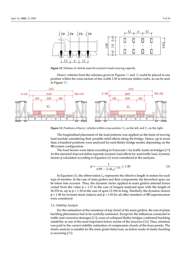
Figure12.
12. Scheme
Scheme of
of vehicle
vehicle used
Figure
used for
for exclusive
exclusiveload‐carrying
load-carryingcapacity.
capacity.
Appl. Sci. 2022, 12, 3788
Heavy vehicles
vehicles from
inin
any
Heavy
from the
the schemes
schemesgiven
givenininFigures
Figures1111and
and1212could
couldbebeplaced
placed
any
10 of 20
positionwithin
within the
the cross-section
cross‐section of free
bebe
seen
position
free width
width3.30
3.30m
mbetween
betweentimber
timbercurbs,
curbs,asascan
can
seen
inFigure
Figure 13.
13.
in
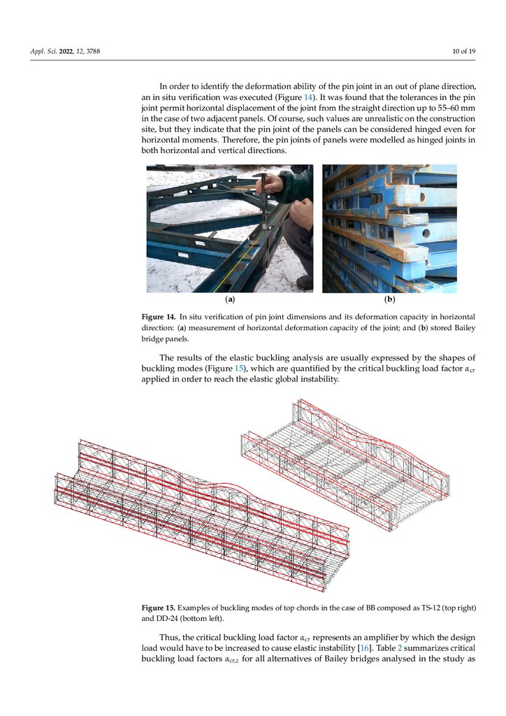
Figure13.
13.Positions
Positionsof
ofheavy
heavy vehicles
vehicles within
within cross-section:
cross‐section: VVnnon
the right.
Figure
onthe
theleft,
left,and
andVeVon
e on the right.
Thelongitudinal
longitudinal placement
placement of the load patterns
The
patterns was
wasapplied
appliedon
onthe
thebasis
basisofofmoving
moving
loadmodule
moduleconsidering
considering their
their possible
possible relief effects
load
effects along
alongthe
thebridge.
bridge.Hence,
Hence,up
uptotomore
more
thanaahundred
hundredpositions
positions were
were analysed
analysed for each
than
each Bailey
Bailey bridge
bridgemodel,
model,depending
dependingon
onthe
the
BBsystem
systemconfiguration.
configuration.
BB
Theload
loadfactors
factors were
were taken
taken according
according to
[19].
The
to Eurocode
Eurocode11for
fortraffic
trafficloads
loadson
onbridges
bridges
[19].
Asthis
thisstandard
standard
does
not
define
separate
dynamic
load
effects
road
traffic
load,
dy‐
As
does
not
define
separate
dynamic
load
effects
for for
road
traffic
load,
dynamic
namic φfactors
ϕ calculated
according
to Equation
(1)considered
were considered
in the analyses.
factors
calculated
according
to Equation
(1) were
in the analyses.
1
1
(1)
1.50
φ