Похожие презентации:
Проведение патентно-лицензионных исследований, упругопластического расчета в SCAD
1.
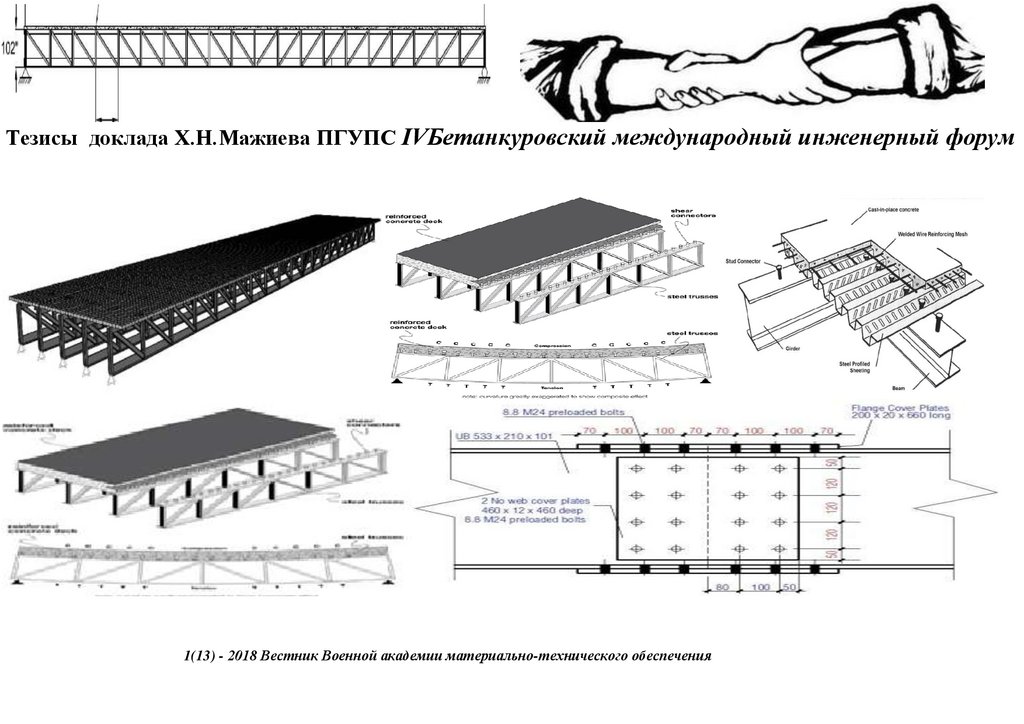
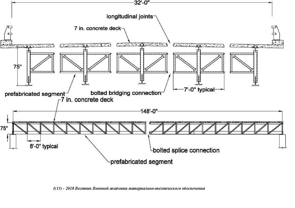
119Проведение патентно-лицензионных исследований, упругопластического расчета в SCAD, 3D-модель конечных элементов,
испытания фрагментов и узлов, монтажных соединений -компенсаторов, секций неразрезных ферм-балок разборного моста с
большими перемещениями на его напряженно -деформированное состояние со встроенным бетонным настилом организацией
"Сейсмофонд" при СПб ГАСУ при проведении НИОКР для дистанционного НТС при Минстрое ЖКХ, Минтрасе,
1(13) - 2018 Вестник Военной академии материально-технического обеспечения
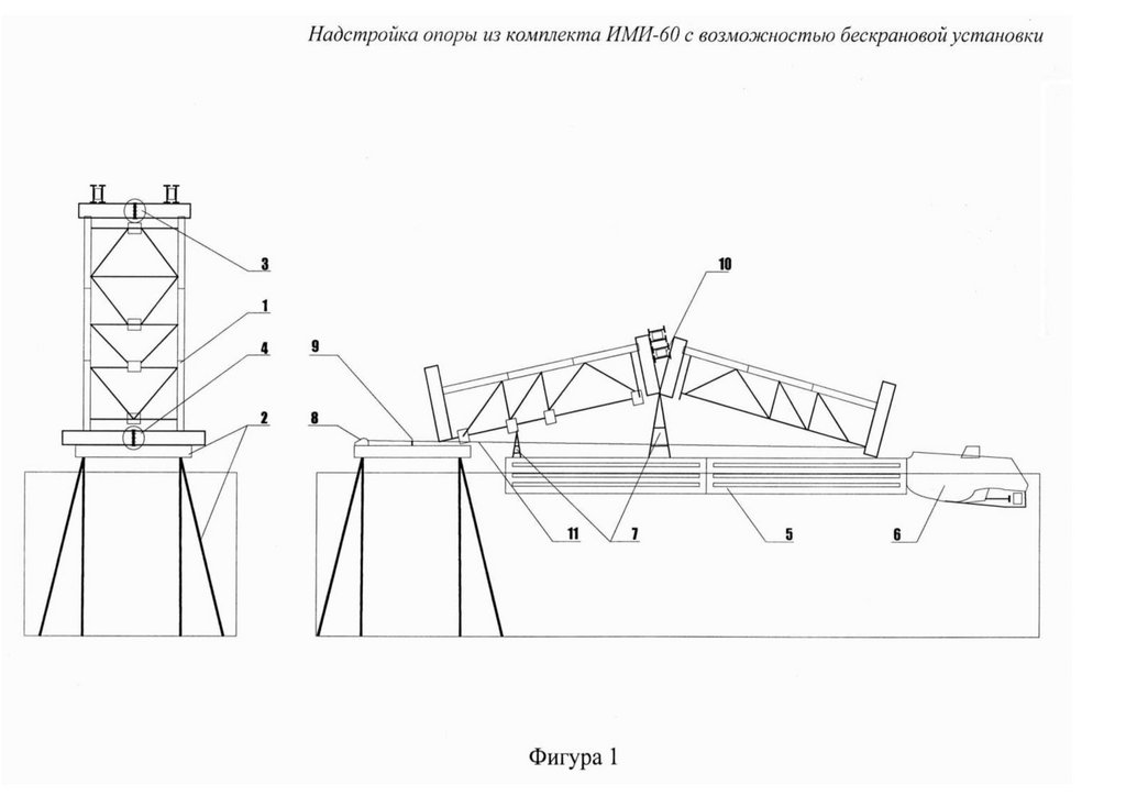
Минпромторге по объекту: Ускоренного строительство сборно-разборной быстро собираемой из предварительно напряженных
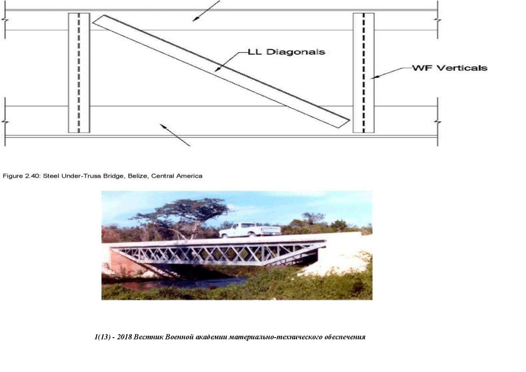
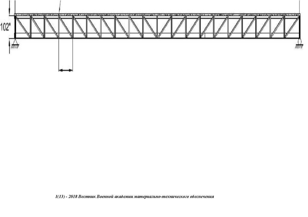
ферм пролетного строения моста ( патент № 222824 ) с нискосходящими раскосами ( патент № 2503783) стальных ферм с
большими перемещениями, самого пролетного строния моста (переправы), сконструированного из упругопластических узлов
2.
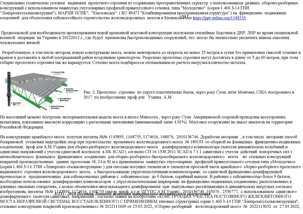
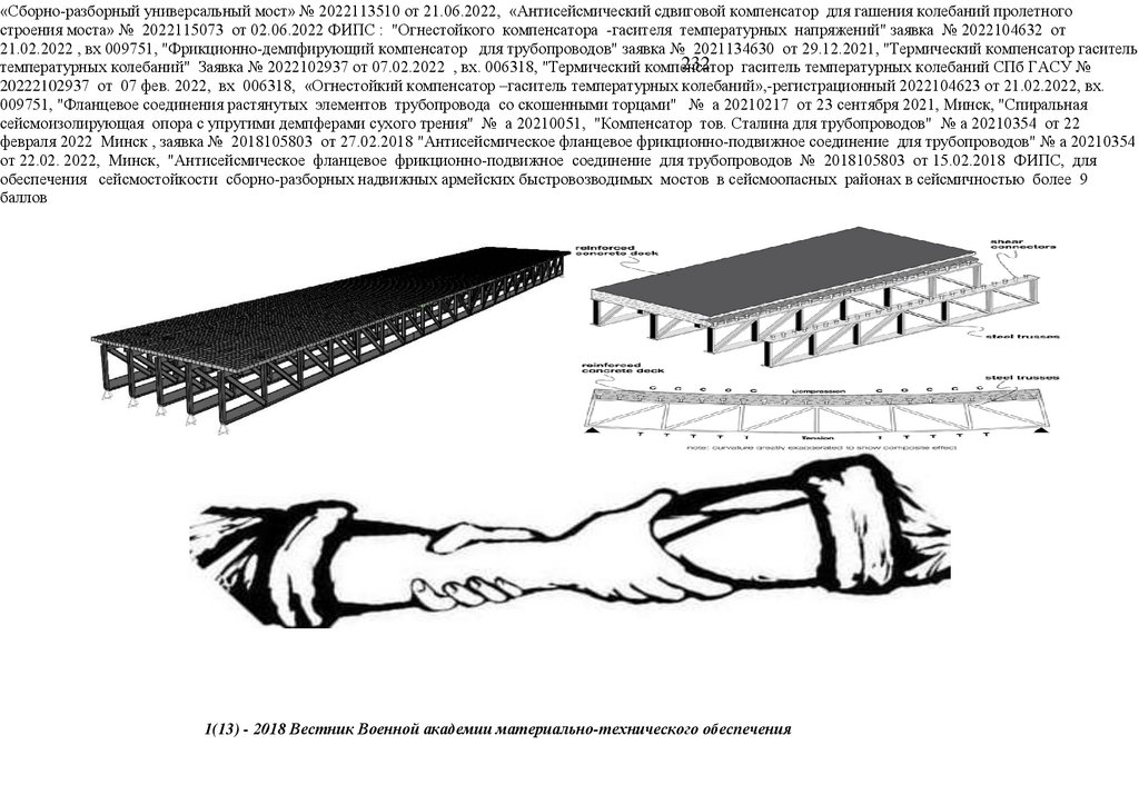
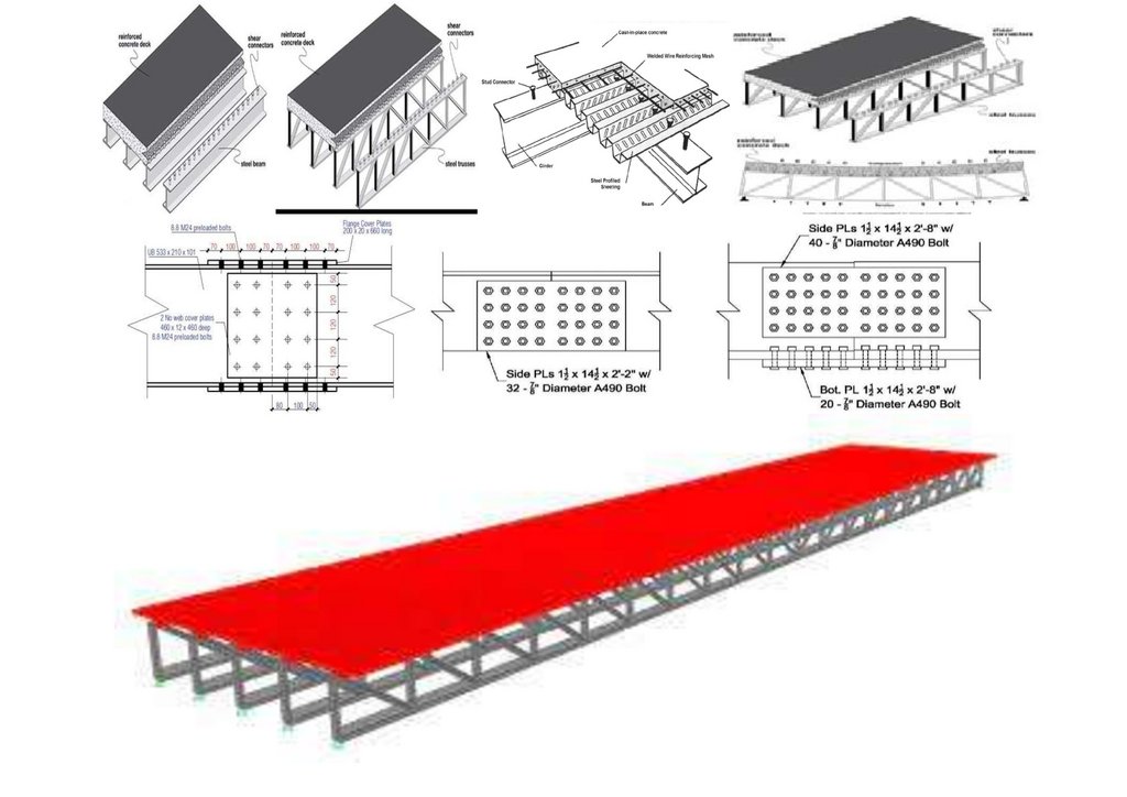
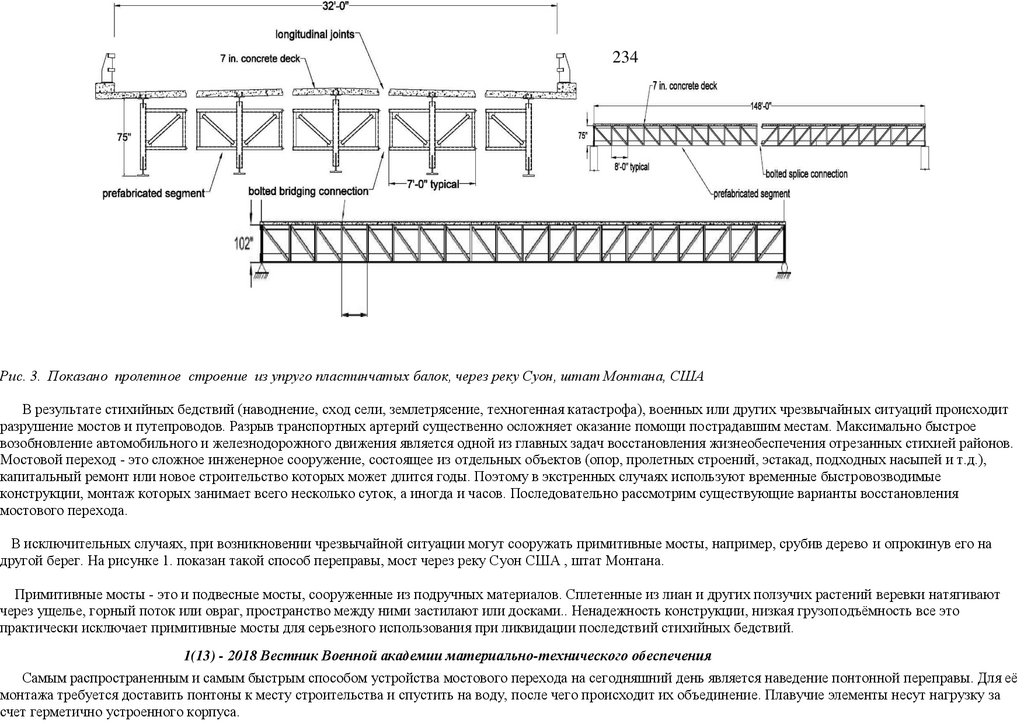
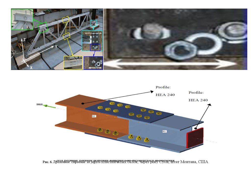
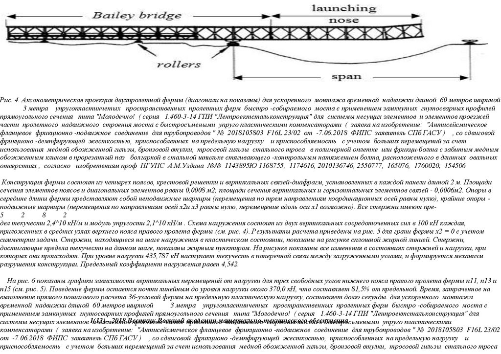
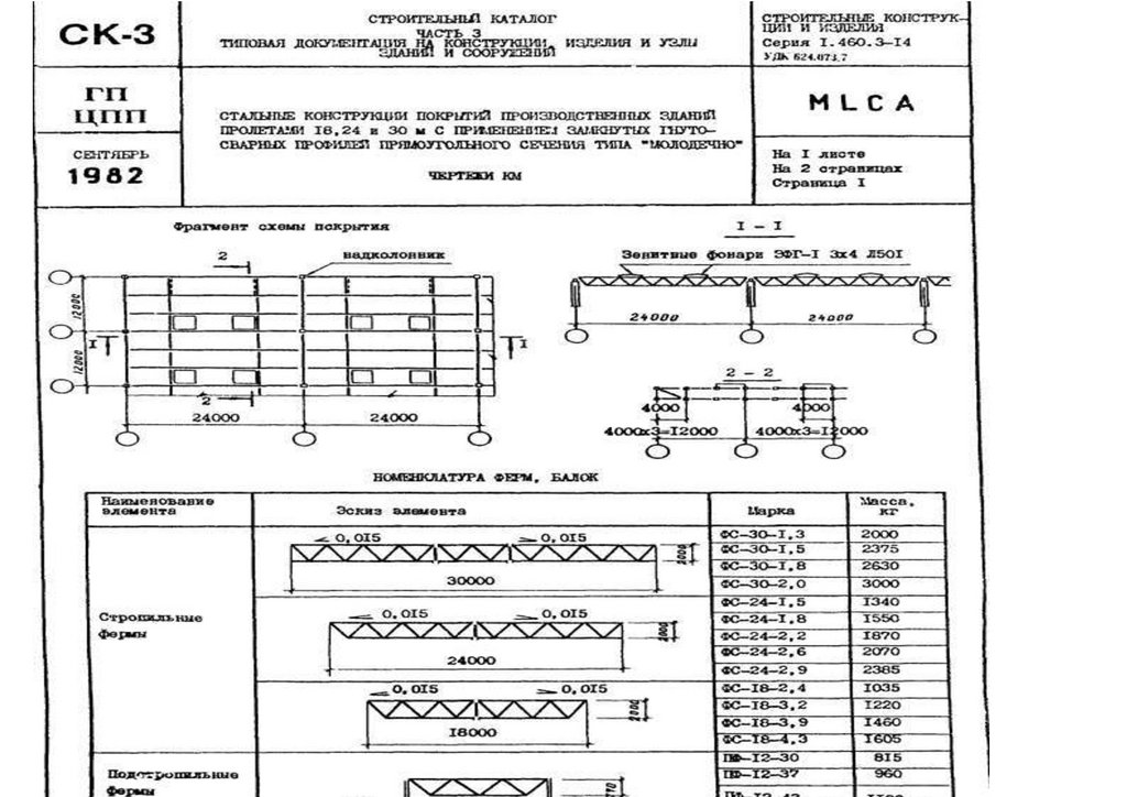
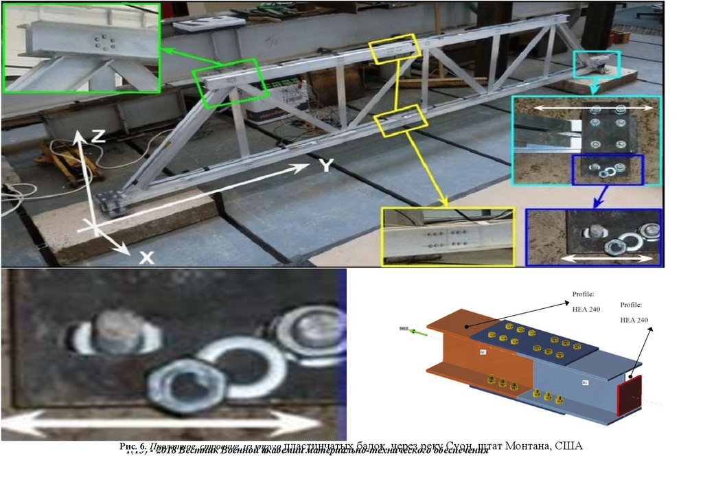
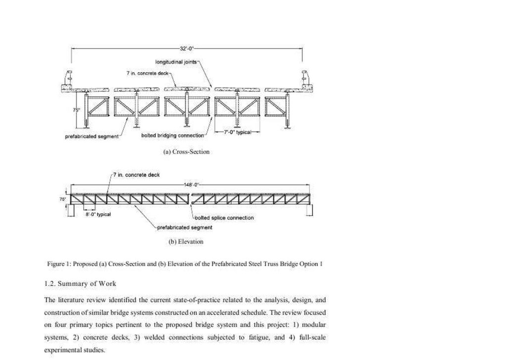
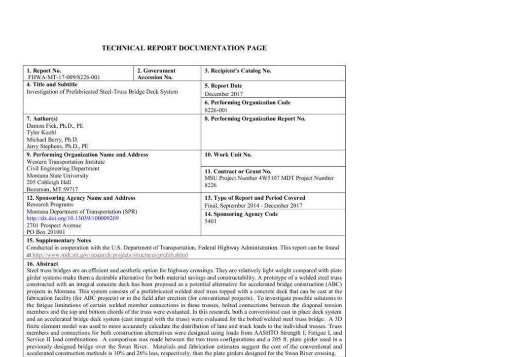
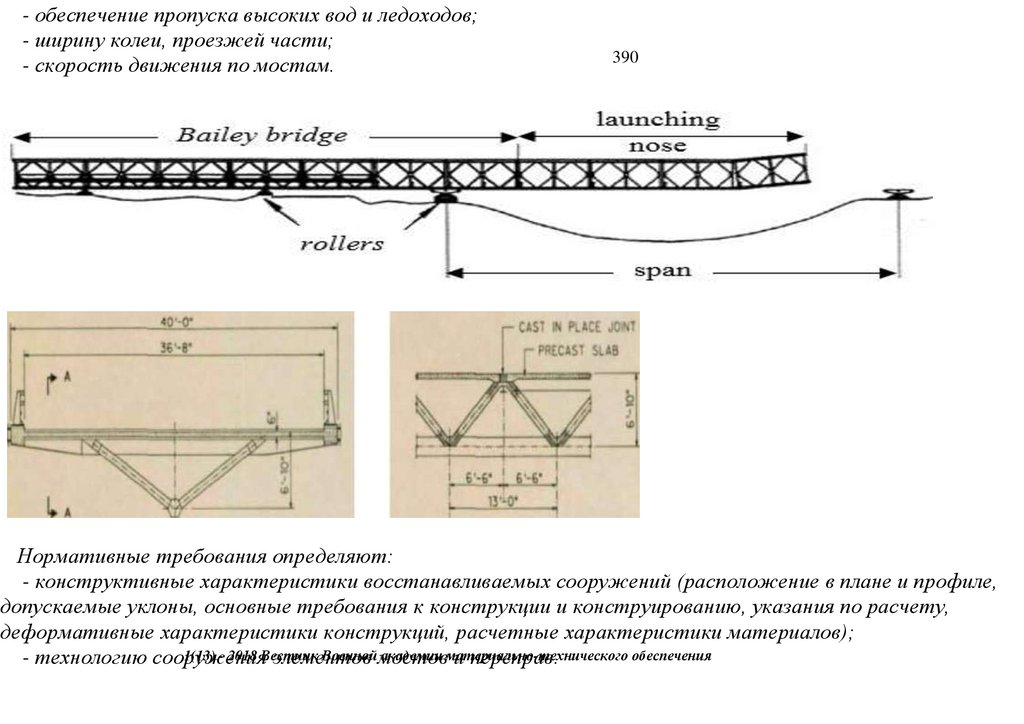
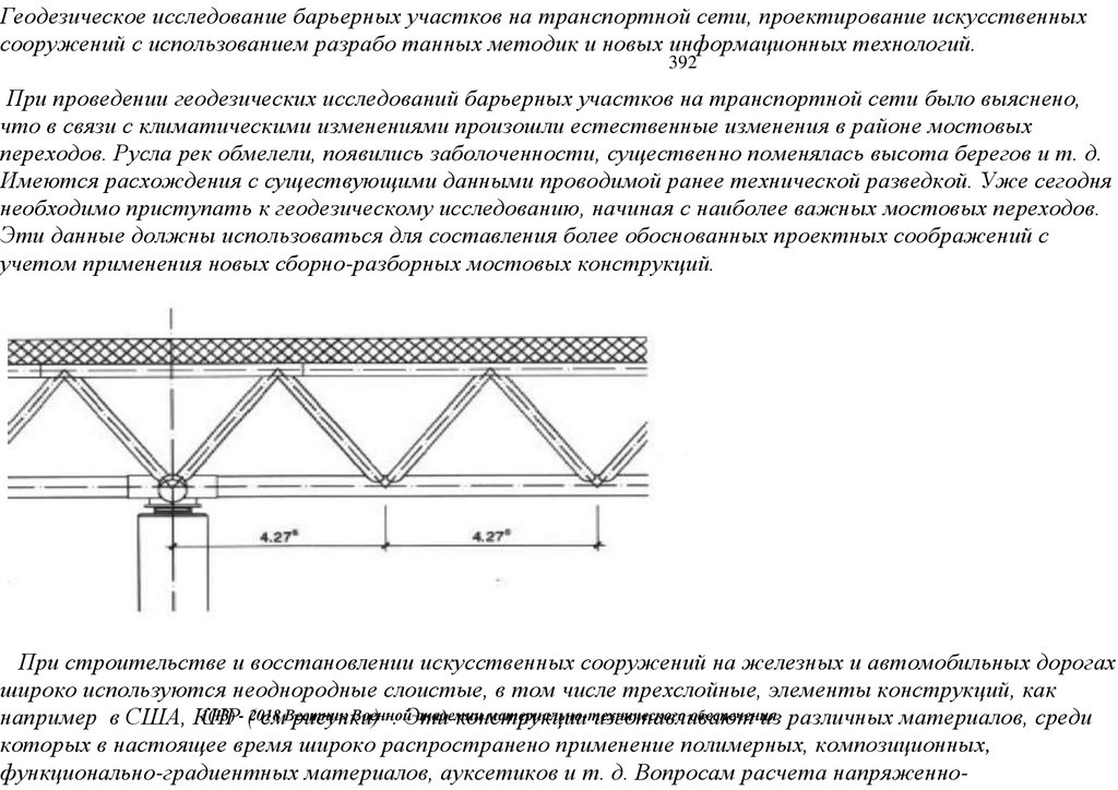
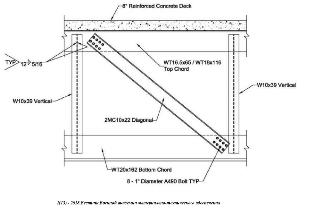
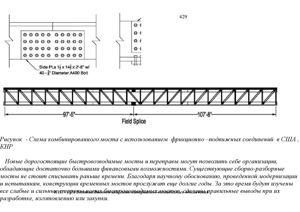
сопряжения, с применением замкнутых гнутосварных профилей прямоугольного сечения типа "Молодечно" ( серия 1.460.314 ГПИ "Ленпроектстальконструкция") по аналогу переправы через реку Суон , в штате Монтана (США), длиной 205 футов ( 60метров ) с натяжными элементами нижнего пояса со встроенным фибробетонным
120 настила в пролетное строение автомобильного
армейского моста
Проведенние патентно -лшцензилоннных исследований, упругопластического расчета в SCAD, 3D-модель конечных элемнтов,
испытания фрагментов и узлов, монтажных соединений -компеннсаторов, секций неразрезных ферм-балок разбороно моста с
большими перемщениями на его напряженнно -дефорпмированное состояние со встроенным бетонным настилом организацией
"Сейсмофонд" при СПб ГАСУ при проведении НИОКР для дистанционного НТС при Минстрое ЖКХ, Минтрасе, Минторге
ФГАОУ ВО «СПбПУ» № RA.RU.21ТЛ09 от 26.01.2017, 195251, СПб, ул. Политехническая, д 29, организация «Сейсмофонд» при СПб ГАСУ. 190005, 2-я Красноармейская
ул. д 4 ОГРН: 1022000000824, т (812) 694-78-10 https://www.spbstu.ru [email protected] [email protected] [email protected] (921) 962-67-78
(аттестат № RA.RU.21ТЛ09, выдан 26.01.2017) [email protected] [email protected]
1(13) - 2018 Вестник Военной академии материально-технического обеспечения
3.
1211(13) - 2018 Вестник Военной академии материально-технического обеспечения
4.
1221(13) - 2018 Вестник Военной академии материально-технического обеспечения
5.
1231(13) - 2018 Вестник Военной академии материально-технического обеспечения
6.
1241(13) - 2018 Вестник Военной академии материально-технического обеспечения
7.
1251(13) - 2018 Вестник Военной академии материально-технического обеспечения
8.
1261(13) - 2018 Вестник Военной академии материально-технического обеспечения
9.
1271(13) - 2018 Вестник Военной академии материально-технического обеспечения
10.
1281(13) - 2018 Вестник Военной академии материально-технического обеспечения
11.
1291(13) - 2018 Вестник Военной академии материально-технического обеспечения
12.
1301(13) - 2018 Вестник Военной академии материально-технического обеспечения
13.
1311(13) - 2018 Вестник Военной академии материально-технического обеспечения
14.
1321(13) - 2018 Вестник Военной академии материально-технического обеспечения
15.
1331(13) - 2018 Вестник Военной академии материально-технического обеспечения
16.
1341(13) - 2018 Вестник Военной академии материально-технического обеспечения
17.
1351(13) - 2018 Вестник Военной академии материально-технического обеспечения
18.
1361(13) - 2018 Вестник Военной академии материально-технического обеспечения
19.
1371(13) - 2018 Вестник Военной академии материально-технического обеспечения
20.
1381(13) - 2018 Вестник Военной академии материально-технического обеспечения
21.
1391(13) - 2018 Вестник Военной академии материально-технического обеспечения
22.
1401(13) - 2018 Вестник Военной академии материально-технического обеспечения
23.
1411(13) - 2018 Вестник Военной академии материально-технического обеспечения
24.
1421(13) - 2018 Вестник Военной академии материально-технического обеспечения
25.
1431(13) - 2018 Вестник Военной академии материально-технического обеспечения
26.
1441(13) - 2018 Вестник Военной академии материально-технического обеспечения
27.
1451(13) - 2018 Вестник Военной академии материально-технического обеспечения
28.
1461(13) - 2018 Вестник Военной академии материально-технического обеспечения
29.
1471(13) - 2018 Вестник Военной академии материально-технического обеспечения
30.
1481(13) - 2018 Вестник Военной академии материально-технического обеспечения
31.
1491(13) - 2018 Вестник Военной академии материально-технического обеспечения
32.
1501(13) - 2018 Вестник Военной академии материально-технического обеспечения
33.
1511(13) - 2018 Вестник Военной академии материально-технического обеспечения
34.
1521(13) - 2018 Вестник Военной академии материально-технического обеспечения
35.
1531(13) - 2018 Вестник Военной академии материально-технического обеспечения
36.
1541(13) - 2018 Вестник Военной академии материально-технического обеспечения
37.
1551(13) - 2018 Вестник Военной академии материально-технического обеспечения
38.
1561(13) - 2018 Вестник Военной академии материально-технического обеспечения
39.
1571(13) - 2018 Вестник Военной академии материально-технического обеспечения
40.
1581(13) - 2018 Вестник Военной академии материально-технического обеспечения
41.
1591(13) - 2018 Вестник Военной академии материально-технического обеспечения
42.
1601(13) - 2018 Вестник Военной академии материально-технического обеспечения
43.
1611(13) - 2018 Вестник Военной академии материально-технического обеспечения
44.
1621(13) - 2018 Вестник Военной академии материально-технического обеспечения
45.
1631(13) - 2018 Вестник Военной академии материально-технического обеспечения
46.
1641(13) - 2018 Вестник Военной академии материально-технического обеспечения
47.
1651(13) - 2018 Вестник Военной академии материально-технического обеспечения
48.
1661(13) - 2018 Вестник Военной академии материально-технического обеспечения
49.
1671(13) - 2018 Вестник Военной академии материально-технического обеспечения
50.
1681(13) - 2018 Вестник Военной академии материально-технического обеспечения
51.
1691(13) - 2018 Вестник Военной академии материально-технического обеспечения
52.
1701(13) - 2018 Вестник Военной академии материально-технического обеспечения
53.
1711(13) - 2018 Вестник Военной академии материально-технического обеспечения
54.
1721(13) - 2018 Вестник Военной академии материально-технического обеспечения
55.
1731(13) - 2018 Вестник Военной академии материально-технического обеспечения
56.
1741(13) - 2018 Вестник Военной академии материально-технического обеспечения
57.
1751(13) - 2018 Вестник Военной академии материально-технического обеспечения
58.
1761(13) - 2018 Вестник Военной академии материально-технического обеспечения
59.
1771(13) - 2018 Вестник Военной академии материально-технического обеспечения
60.
1781(13) - 2018 Вестник Военной академии материально-технического обеспечения
61.
1791(13) - 2018 Вестник Военной академии материально-технического обеспечения
62.
1801(13) - 2018 Вестник Военной академии материально-технического обеспечения
63.
1811(13) - 2018 Вестник Военной академии материально-технического обеспечения
64.
1821(13) - 2018 Вестник Военной академии материально-технического обеспечения
65.
1831(13) - 2018 Вестник Военной академии материально-технического обеспечения
66.
1841(13) - 2018 Вестник Военной академии материально-технического обеспечения
67.
1851(13) - 2018 Вестник Военной академии материально-технического обеспечения
68.
1861(13) - 2018 Вестник Военной академии материально-технического обеспечения
69.
1871(13) - 2018 Вестник Военной академии материально-технического обеспечения
70.
1881(13) - 2018 Вестник Военной академии материально-технического обеспечения
71.
1891(13) - 2018 Вестник Военной академии материально-технического обеспечения
72.
1901(13) - 2018 Вестник Военной академии материально-технического обеспечения
73.
1911(13) - 2018 Вестник Военной академии материально-технического обеспечения
74.
1921(13) - 2018 Вестник Военной академии материально-технического обеспечения
75.
1931(13) - 2018 Вестник Военной академии материально-технического обеспечения
76.
1941(13) - 2018 Вестник Военной академии материально-технического обеспечения
77.
1951(13) - 2018 Вестник Военной академии материально-технического обеспечения
78.
1961(13) - 2018 Вестник Военной академии материально-технического обеспечения
79.
1971(13) - 2018 Вестник Военной академии материально-технического обеспечения
80.
1981(13) - 2018 Вестник Военной академии материально-технического обеспечения
81.
1991(13) - 2018 Вестник Военной академии материально-технического обеспечения
82.
200Condition Assessment and Adaptation of Bailey Bridges as a Permanent Structures
Barasa Anthony Kusimba
1,*
,
Tshewang Rinzin
2
,
Yuki Banno
1
and
1(13) - 2018 Вестник Военной академии материально-технического обеспечения
83.
201Koji Kinoshita
1
1
Department of Civil Engineering, Gifu University, 1-1 Yanagido, Gifu 501-1193, Japan
2
Department of Roads, Ministry of Works and Human Settlement, Gomphu, Zhemgang 34001, Bhutan
*
Author to whom correspondence should be addressed.
Appl. Sci. 2022, 12(22), 11673; https://doi.org/10.3390/app122211673
Received: 6 October 2022 / Revised: 8 November 2022 / Accepted: 12 November 2022 / Published: 17 November 2022
(This article belongs to the Special Issue Advanced Technologies for Bridge Design and Construction)
Download
Browse Figures
Review Reports
Versions Notes
Abstract
The present study assessed the Bailey Bridge’s condition and investigated its adaptation as a permanent structure, targeted the Acrow Bailey Bridge in Japan. Field diagnostic loading experiments were performed under various loading
conditions, such as dynamic and static loading tests. The onsite data were obtained using a transducer, friction strain gauge, target measurements for the image processing approach, and accelerometer. From the field measurements, the
deflection and stresses of the bridge were found to operate within the linear elastic region. The bridge was then accurately modeled based on the in situ geometric configuration of the bridge, and Finite Element Analysis was performed.
The model’s accuracy was validated with the onsite data under the linear elastic domain. The model was deployed to check for resistance of critical members. A nonlinear analysis based on the linear and nonlinear buckling method was
performed to determine the subject bridge’s Serviceability Limit State and Ultimate Limit State. The results showed that the first out-of-plane eigenvalue buckling analysis could monolithically assess bridge members. Further, the study
established digital twin models resolve for historical data through in situ modeling measurements. Therefore, the findings obtained in this study highlight the bridge’s Structural Health Condition, bearing capacity, and propose a framework
for adaptation as a permanent structure.
Keywords:
bailey bridge; bearing capacity; bending moment; deformation; deflection; static and dynamic loading; historical data
1. Introduction
1.1. Background
A Bailey Bridge is a prefabricated truss bridge type whose symmetrically bending moments vary from maximum to zero from the center span to the end posts. This aspect is fundamental during their design because the end bays are
not entirely used, exposing the center bays to maximum stress [1]. Bailey Bridges were initially meant for military use. However, their benefits have been diversified from temporary to semi-permanent or permanent due to their ease of
transportation, low cost, flexible structural form, onsite fabrication, and versatility in accommodating various loading requirements [2]. The panel elements are interchangeable, making them easy to assemble by pinning the components
under different configurations. It takes at least 40 min for a simple combination of double truss employing the cantilever launching method short of falsework [3]. Structural degradation due to loss of parts is expected; primarily, loose pins
that readjust during the dynamic movement of traffic have been reported. Additionally, they are subject to maintenance issues and lack of historical data [4], such as the bearing capacity. Therefore, it is advisable to assess their structural
integrity.
To verify the load-bearing performance of an actual Bailey Bridge, Yi et al. [4] King et al. [5] and Khounsida et al. [2,6] are hereafter worth mentioning. The authors [2,4,6] exploited the Diagnostic load test using Dynamic and Static
Loading (DSL) to certify the bearing capacity for both in-service [2,6] and out-of-service bridges [4]. Diagnostic load testing is meant to assess the structural response of a bridge, and update or calibrate an analytical model for decisionmaking. The calibrated model is then deployed to evaluate the load rating factors, particularly to determine load rating and safety. Conventionally, the loads applied are below the bridge’s capacity—similar to serviceability limit state
conditions; hence larger loads are extrapolated. Consequently, Yi et al. established that the design drawing was unavailable during the load rating of the ‘Engineers Bridge’ pinned arch bridge. Three targets were selected, ¼ span, midspan, and ¾ span, to establish deflection using a total station with an accuracy of 0.2 mm. The author modeled the bridge using existing onsite geometry for the bridge to be analytically examined and compared the deflection results with
field measurements. The author went further and established the load rating based on the serviceability and ultimate limit of the bridge using the current codes, demonstrating an approach for establishing the bearing capacity [4]. On the
other hand, King et al. found that to evaluate the structural response of a Bailey-type Bridge, actual loading conditions should be tested, and a numerical model employed to examine the nonlinear response. Under laboratory testing the
author used a 130-t Universal dynamic Servo-hydraulic Tester to simulate various loading conditions and Linear Variable Differential Transformer (LVDT) displacement sensor to monitor deflections [5]. Further, Khounsida et al. determined
the Bailey Bridge response through onsite experimentations and structural analysis of a bridge in Laos [6]. The author acquired on-site data statically by displacement transducers and total station, and dynamically using an accelerometer
positioned at optimum locations along the girders for maximum deflection. In each of these studies, the evaluation of load-bearing performance by linear or nonlinear finite element analysis of digital twins is based on actual and on-site
member measurements. Therefore, it is thought that appropriate maintenance and management of a permanent bridge can be performed by clarifying the bearing capacity and ensuring the conversion from a temporary bridge to a
permanent bridge.
2018 condition
Вестник
Военнойitsакадемии
обеспечения
The present study aims to assess a1(13)
Bailey -Bridge’s
and investigate
adaptation as материально-технического
a permanent structure. The Sukumo bridge
was targeted, the only Bailey Bridge type in Uchiko Town, Shikoku Island, Japan. First,
diagnostic loading field experiments were performed through DSL tests to examine the static and dynamic behavior of the Sukumo bridge. The structural responses were determined both statically and dynamically. The LVDT displacement
transducer and image processing approach assessed the deflection on static loading conditions, while the Micro-electromechanical Systems (MEMs) accelerometer for dynamic loading deflection [7,8]. Frictional strain gauges [9,10]
accounted for the strains. Then, the bridge’s Finite Element Analysis (FEA) model (digital twin) was developed, and its validation was confirmed compared to the field measurement results. Further, nonlinear analysis was performed using
the validated model to examine the load bearing capacity of the Sukumo Bailey Bridge. Based on these, the possibility of adaptation of the Sukumo bridge as a permanent structure was evaluated.
84.
1.2. Bailey Bridge Structural CharacteristicsNumerous bridges have been made from the typical Bailey Bridge panel using different designs and material strengths:
1.2.1. First Generation
The Bailey Bridge was designed by Sir Donald Bailey and patented in 1943 [3,4]. It was the basis for the current modular bridge. The bridge was a transportable, prefabricated truss bridge realized by developing new construction
methods and panel connection systems from the Callender-Hamilton Bridge [11,12]. Each member of the Bailey Bridge is standardized, as shown in Figure 1a. Depending on the span length and the number of lanes, the strength of the
girders can be increased by stacking multiple panels of typical dimensions 3050 mm × 1550 mm or connecting them vertically. In addition, it uses hollow high-grade, lightweight steel material that can be transported manually and does not
require special tools. The first-generation Bailey Bridges are classified into M1, M2, and M3. Bailey M1 is the initial type, while the predecessor Bailey M2 was designed by widening the road by 12% feet, and Bailey M3 was an
improvement of Bailey M2 [13].
202
Figure 1. (a) Typical Bailey Bridge, (b) Mabey Bailey Bridge, (c) Acrow Bailey Bridge and (d) M2 typical end shear/post.
1.2.2. Second Generation
After the Bailey Bridge patent expired in 1970, Thos Storey Engineers Ltd. and Mabey Johnson Ltd. introduced the Acrow 1, Acrow 500, and Mabey Super Bailey & Compact 100 in that order. The Acrow 1 Bailey Bridge had a
diamond panel configuration with the transom moving in the diamond panel. It was conspicuous due to its method of eliminating stress related to pinhole sag and global deflection due to the diamond configuration. The design could
accommodate two transoms per panel. On the other hand, the Acrow 500, introduced in 1987, used a single universal transom at each bay, retaining its panel dimension illustrated in Figure 1c. The Mabey Super Bailey was introduced in
1967 with improved detail and strength than the typical Bailey but with similar panel dimensions [11]. The lower chords panel used bolts and facing plates on the top chord for strength. Its predecessor, the Mabey Compact 100 [13,14],
used high-grade steel and channel sections as bracing frames with one transom per panel. The second generation of the Bailey Bridge is lighter than the original Bailey Bridge and uses the same end post configuration with varying
dimension as the M2-type typical Bailey Bridge demonstrated in Figure 1d—measurements from site.
1.2.3. Third Generation
The Mabey Compact 200 and Acrow 700 came with increased panel depth, approximately 50% higher panel height, and 20% more potent in shear than the original Bailey Bridge demonstrated in Figure 1b,c. The depth improved its
stability and potential to accommodate a wider roadway of 7.3 m. Mabey Compact 200 was used during the construction of the Baker bridge in 2009 in Cambria, Britain. The Acrow 500 was replaced with the Acrow 700, later adopted as
Acrow 700XS [11]. The Acrow 700XS were assembled for recovery efforts at ground zero of the World Trade Center, during the terrorist attack, in record time. The structure was erected on prefabricated piers, moving a record 1.8 million
tons of debris. Additionally, it was also operational during the rebuilding process. On the other hand, New Jersey Turnpike Authority employed the 700 series to create a diversion during the upgrade of the existing bridge in a record 15 min
[11].
2. Field Experiment
2.1. Target Bailey Bridge
Figure 2 shows the target Bailey Bridge referred to as the Sukumo Bailey Bridge. The bridge is in Uchiko Town, Kita District, Ehime Prefecture, along the junction of Route 56 highway. The bridge was built in 1997 as a temporary
structure to serve as an access for constructing one of the Matsuyama Expressway (E56) piers across the Nakayama River. The bridge spans 31.81 m, having a carriage width of 4.0 m, as shown in Figure 2a–c. The bridge has an alleged
loading capacity of 25 T, sourced from interviews with Uchiko Town municipal offices. It is a third-generation Bailey Bridge Acrow type Double Single Reinforced (DSR), with a panel of 3.976 and 2.134 m, length, and height, respectively.
1(13) - 2018 Вестник Военной академии материально-технического обеспечения
85.
203Figure 2. (a) Sukumo bridge. (b) The front view—end shears/posts. (c) The side view—panel sections.
2.2. Load Test
Load tests were performed statically and dynamically to examine the static and dynamic behavior of the Sukumo Bridge. Before the loading tests, three types of loading cases were selected, not to exceed the Sukumo bridge’s
presumed loading capacity (i.e., 25 Tons). It was assumed that the loads chosen were within the elastic region.
Equation (1) summarizes the approach for load selection. A bridge (Bailey) has an elasticity range that departs from its linear elastic region when the applied loads exceed its bearing capacity. This principle is critical in the
structure’s bearing capacity that dictates its capacity—Serviceability Limit State (SLS). Hence, it refrains the structure from plastically deforming (aid in predicting various effects of load on a structure) when the loads are beyond the design
capacity—Ultimate Limit State (ULS). The decking joints are critical, considering they receive the full effect of dynamic hammering of loads; it is prudent not to exceed the design tolerance [5,6]. Therefore, the choice of loads was dictated
by the principle of superposition summarized in Equation (1), where δi-n denoted displacement (mm), Fi-n denoted Load (Tons), and m denoted slope.
⎧⎩⎨⎪⎪
(δi,Fi),
Fi=mδi+Ci
(δii,Fii), Fii=mδii+Cii(Fi+Fii)=m(δi+δii)+(Ci+Cii)
(1)
Table 1 shows the three types of loading cases. Loading cases are 1 was a car whose weight was 1.57 Tons, 2 was a Truck whose weight was 12.24 Tons, and 3 was a crane whose weight was 19.66 Tons, excluding the average
weight of the driver weighing 55 kg. These weights were loaded statically and dynamically onto the bridge. After this, the loading conditions are explained in detail.
Table 1. Three types of loading cases.
2.2.1. Static Loading Condition
Figure 3 shows the static loading conditions. Due to the constrained width of the structure, 4.0 m; symmetrical loading was limited. Hence, the Load’s Center of Gravity (COG) was established from the load axles for optimum
positioning of the load cases, as shown in Figure 3. The bridge deck was demarcated widthwise 0.74, 0.93, and 0.91 m from the center of the lane, as illustrated in Figure 3. The dimensions were based on the loading cases. Lengthwise,
the structure was divided into 6 sections with 5 targets at 5.0–5.905 m along the bridge t1 to t5. Loading case 1 was set at the mid-span of the Sukumo Bridge (t3), while loading cases 2 and 3 were set at targets t1 to t5, ensuring the axles
COG coincides with the target axis as indicated in Figure 3a–c.
1(13) - 2018 Вестник Военной академии материально-технического обеспечения
86.
204Figure 3. Static loading conditions (unit: m): (a) Loading case 1; the target set at midspan (t 3) for measurement of displacement; Metadata: Car, wheel spacing of 1.48 m and axle spacing of 2.85 m. (b) Loading case 2; targets are set
along the bridge span t1–t5; metadata: Truck, wheel spacing of 1.85 m and axle spacing of 5.7 or 1.37 m. (c) Loading case 3; targets are set along the bridge span t 1–t5; metadata: Crane, wheel spacing of 1.82 m, and axle spacing of 3.20
m.
2.2.2. Dynamic Loading Condition
The dynamic load test under ambient conditions was conducted such that the car, truck, and crane drove over the bridge from the left to right banks of the span portrayed in Figure 3. RL and LR denoted the situation from the Right
bank to the Left bank and vice versa. During the dynamic loading test, a minimum velocity of 3 km/h and a maximum of 20 km/h was maintained to establish the global dynamic behavior of the bridge.
2.3. Measurement Plan
The underlying reason for instrumenting [15] the bridge was to examine the response of the bridge under various loading conditions. The global deformation or deflection of the bridge is a measure of its stiffness [16,17]. On the other
hand, stresses will give us the local behavior of elements that might prompt fatigue evaluation of the various elements [15]. Measurement instruments at our disposal were limited to the LVDT—displacement transducers, Friction strain
gauge, image processing, and MEMs accelerometer. The transducers and image processing determined the deflection angle and deformation. On the other hand, the strain gauges determined the local strains during loading, while the
accelerometer established the structural dynamic response during loading.
2.3.1. LVDT Displacement Transducer Setting
Figure 4a shows the set locations of the LVDT—displacement transducers. CDP-type [18] LVDT displacement transducers were exploited with a capacity of 25–100 mm, due to their stability, nonlinearity of 0.1% Rated Output,
sensitivity of 100–500 (×10−6 strain/mm), and
accuracy
of ±0.1%.
They were
set at the end
of the right and
left end shears/post, attached to the bottom
chord by a rigid magnet, demonstrated in Figure 4b,c, denoted as R1, R2, R3, R4, L1,
1(13)
- 2018
Вестник
Военной
академии
материально-технического
обеспечения
and L2 to achieve a good deflection profile. The deflection is attributed to the composite actions between the panels’ chords and the respective members. Additionally, the transducers exclusively determined the displacement
measurements under static loading conditions. To achieve the profile along both spans at intervals of approximately 5.0 m, the deflection angle from a point normal to the bearing on the base plate was determined from Equation (2). The
latter was diagrammatically summarized in Figure 4d. LVDT displacement transducers were set on the abutment from a point 400 mm from a point normal to the bearing on the base plate presented in Figure 4b,c. They were then
connected to a data logger DC-204R for recording voltage output emanating from the LVDT Transducer. It, in this way, acted as a link to the PC, controlled by DC-7630 Tokyo Sokki as the system interface with multichannel capabilities.
θ=sin−1{V0−V1r}
87.
(2)where θ—Deflection angle, V0—Initial transducer reading, V1—Transducer reading after loading, r—Distance between LVDT displacement transducer shaft to a point on the base plate and normal to the bearing.
205
Figure 4. (a) Measurement instruments setup, (b) LVDT displacement transducer setup, (c) Determination of the deflection angle.
2.3.2. Frictional Strain Gauge Setting
Figure 4a,d also show the location of the Frictional strain gauges [9] attached. The location was chosen to understand the symmetrically bending moments of the Sukumo bridge. Bailey Bridges have maximum compressive stresses
at the center bays’ top chord [1,2,14]. Hence, the gauges were placed on the top chords and both sides of the inner bridge panels’ web section. They were denoted in relation to the flow of the stream where Us and Ds meant Up-stream
and Down-stream likewise. As a result, they were symmetrically skewed along the center line, Us2 and Ds1. On the other hand, Us1 and Ds2 were placed approximately 9.015–9.285 m from the center line completing the skew symmetry
as detailed in Figure 4a. Their placement on the top girder ensured maximum global response. The magnetic frictional strain gauges were the FGMH series with a gauge length of 1.0 mm. They consisted of a rubber layer on their contact
surface and a magnetic ring pressing against the web-section on the top chord. Strains are recorded due to friction caused by the target surface because of acoustic emissions [9]. They were wired to the end shears of the bridge with
insulated, low-resistance copper wires approximately 15 m long on both spans. They were then connected to a quarter bridge (for voltage input) and a microprocessor data logger DC-204R system through a converter connected to a PC
as the controller—DC-7630 Tokyo Sokki for calibration, manipulation, visualization, and data extraction interface. The controller had eight channels on either side of the bridge for the strain gauge, and the LVDT displacement transducer
had a shared interface.
2.3.3. Target Setting for Image Processing Approach
Figure 5 shows the configuration of the image processing approach employing MOVIAS neo by Nac. Image Technology Co., Ltd. located in Akasaka, Minato City, Japan, which is widely used in automotive crash test analysis [7].
The targets were Quadrants deployed to track the frames for deflection. They were set at 5.0 m at t 1 to t5 on the top chord of both the left and right spans [7]. Figure 5a presents the target setup along one of the spans. The approach is an
improvement from conventional totals station that only monitors one point, leading to limited information rather than point cloud data [8,17]. The deformation of the targets was recorded from different monochrome cameras, shooting
angles, and resolutions of A: 4608 × 3456 pixels, B: 5472 × 3648 pixels and C: 5184 × 345 pixels. Figure 5b illustrates how the image processing approach determined the deformation. A preselected, fixed reference point was established
during the experiment for calibration using the recommended spatial resolution on the user interface—the guard rail bolt, as shown in Figure 5c. The reference point was then used to determine the displacement in reference to the target
Quadrants. With a minimum resolution of 15 pixels, high center detection accuracy can be achieved on the quadrant. The target was set so that the pixel luminance information coincides with the template size [7]. Hence, the difference
(Δh) is then resolved as the deflection value encapsulated in Equation (3). The instrument was only used during static loading due to scan time delays.
(D0−Dn )=Δh
(3)
where, D0 Deformation/deflection reading after loading, Dn Deformation/deflection reading before loading, and Δh Deformation or deflection in mm.
1(13) - 2018 Вестник Военной академии материально-технического обеспечения
88.
206Figure 5. (a) Image processing setup, Targets are set at specific spots, and structural responses are determined from the recorded events. (b) Deflection determination was based on target/quadrant vs. fixed bolt relationship. (c)
Preselected rigid reference point—the guard rail bolt.
2.3.4. Accelerometer Transducer Setting
Figure 4a also shows the set location of the MEMs accelerometer transducer, which is an INTEGRAL PLUS sensor with 15-min real-time deflection measurement capabilities. The sensor was adopted under a new technology
information system within the Ministry of Land, infrastructure, transport, and Tourism Japan for inspection support. It is suitable for bridge spans less than 40 m, with a maximum running test of 40 km/h and an accuracy of 0.08 mm for steel
bridges [19]. It was placed at the center span, as shown in Figure 4a, on the upstream girder side of the structure. It measured the dynamic behavior of the structure [19,20,21,22]. The measure of the vertical displacement of the structure
against time under different loading conditions was meant to determine the in-service behavioral response. Such conditions illustrate the ambient condition of the structure relating to its day-in response [19].
Several parameters are employed in evaluating a structure’s dynamic condition, such as the natural frequency, vibration modes, damping, and Dynamic Amplification Factor (DAF) [23,24]. Among them, DAF is considered a critical
parameter introduced in bridge design codes, for example, AASHTO 1996, 1997, and Eurocode 1-2. It establishes the structures’ inherent uncertainties that correlate with other dynamic effects, such as pavement condition and extent of
deterioration. Thus, it can contribute to bridges’ structural condition. Therefore, a structural condition assessment of the Sukumo bridge was based on DAF. It was calculated using Equation (4) [25,26].
DAF=(1+μ)=1+{Rdyn−RstatRstat}
(4)
where Rdyn, Rstat, and μ denoting maximum dynamic, static response, and dynamic amplitude (deflection or deformation).
3. Results of the Field Experiment
3.1. Static Behavior
Figure 6 shows the deflection angle calculated from the transducer measurement and image processing approach. In this figure, three loading cases are shown; case 1 (1.57 Tons), case 2 (12.24 Tons), and case 3 (19.66 Tons).
The deflection angle calculated from the transducer on Loading case 1 ranged from 0.0004–0.0066 with a difference of 0.01; between R4 and R3, causing a deflection ranging from 0.0030–0.0460 mm. On the other hand, Loading case 2
had a deflection angle ranging from 0.0166–0.0596 with a difference of 0.04 and deformation of 0.1160–0.4160 mm; while Loading case 3 recorded deflections from 0.0278–0.0925 with a residual of 0.06 with deformation of 0.1940–0.6460
mm. A deformation θ less than 0.1 from Equation (2) was considered reasonable. It meant the structure operated using the concept outlined in Equation (1) (principle of super-position). However, transducers R3 and R4, revealed in Figure
6c,d, exhibited higher deflections from Loading case 2. It was suspected to be due to the calibration and sensitivity of the transducer to higher loads. On the same note, the image processing approach recorded deflections increasing from
Loading cases 1–3, that is, Loading case 1—0.0079 (0.0548 mm); Loading case 2—0.0340 (0.2377 mm), and Loading case 3—0.0492 (0.3435 mm), with minimal mean deviation from the transducer measurements of 0.0043, 0.0016 and
0.004 from Loading case 1 in that order, exemplified in Figure 6. Significant ∆θ residuals were observed between the displacement transducer and image processing approach. The Bailey Bridges consist of several panels [27] on each
- 2018
академии
span connected with pins whose tolerances1(13)
vary. As
a result,Вестник
the pins resetВоенной
during loading
[1], leading toматериально-технического
large deflections depending on the spans’обеспечения
side (left or right span). Moreover, the bending moment along the panels does not assume
a perfect circular curve because the spans are an assembly of panels having approximately similar rotational angles as opposed to a single continuous beam using the second theorem ( t2/1=Ax¯/EI) in Moment area method.
Whereas t2/1 tangetial deviation, A area under the curve on a cantelever beam, x¯ centroid, EI flexural rigidity (E modulus of elasticity and I moment of inertia) [26,27]. Therefore, determining deflection from different locations will give rise
to varying results, LVDT at 400 mm, and image processing method at 5.905, 10.905, and 15.905 m. Further, the image processing method’s targets were on the top chord which experienced compression during loading. On the other hand,
the displacement transducer was on the lower chord, which was vulnerable to tension [2,27]. The phenomena correspondingly affect the profile hereafter presented in Figure 7.
89.
207Figure 6. Deflection angles calculated from transducer and image processing measurements and FEA at (a) R1. (b) R2. (c) R3. (d) R4. (e) L1. (f) L2.
Figure 7. Mean deformation profiles under loading cases 1, 2, and 3 along the five targets on the bridge span.
Figure 7 shows the deformation profiles along the bridge span. From the results, the profile showed symmetry at the center span, increasing with loading cases 1 to 3 on both the transducer measurement and image processing
approaches. The deformation at the center span was higher with the transducer (tension members) than with the image processing approach (compression members) [2,27] with 2.18–14.42 mm. The results show a linear-elastic behavior
having approximately similar characteristics in both approaches. Moreover, the deformation profile indicated an increasing bending moment from the end shears to the center of the span. The phenomena were similar in both spans. In
reference to the AASHTO 2010 Bridge design specification, the permissible in-service loading is span/800 [28], translating to a maximum allowable deflection of 39.73 mm under load. Additionally, the theoretical pinhole sag ( Sag=dn2/8)
of 28.48 mm for self-weight, where d was 3.56 (constant), and n number of bays. From the experimental results, the maximum deflection obtained was 14.42 mm from the transducer’s influence line that is below the prescribed limit.
Figure 8 illustrates the load-strain and stress-strain relationship. Bailey Bridges experience significant stress at mid-span than end-shear during loading [14]. This aspect is of great importance in designing truss structures ensuring
reinforcement of the critical elements at mid-span that are fully stressed. The strains were established during loading cases 1–3. Figure 8a,b indicates the effects of strain with loading. The strains increased with the loading with no
anomaly to indicate underlying local issues such as fatigue. The strains had similar characteristics apart from differences due to the strain gauge placement distances, which were not precisely co-linear (Us1 & Ds1) and alternate (Us2 &
Ds2). However, a symmetric relationship varies from the center, as shown in Figure 8a,b. The situation is critical for fixed-panel bridges indicating that the end posts/shears are not fully utilized. Consequently, reinforcing the center bays
ensures uniform distribution of stresses. The panel stress was calculated using averaged values of Us1 and Ds1 with a modulus of elasticity of 2.0 × 10⁵ MPa for a steel superstructure with a concrete deck to establish the linearity. Figure
8c shows the stress-strain relationship. It was clear that the bridge operated within the linear elastic range. Moreover, the stresses experienced in Loading case 3 correspond to a similar study on the same bridge [29].
1(13) - 2018 Вестник Военной академии материально-технического обеспечения
90.
208Figure 8. Load vs. strain relationship at (a) Downstream. (b) Up-stream. (c) Stress vs. strain relationship.
3.2. Dynamic Behaviour
Figure 9 illustrates the structural dynamic response. Figure 9a–c relay the various loading cases, indicating the structural dynamic response. Measurements were recorded from cases 1–3 with an average speed of 3–20 km/h
practicable to prompt the dynamic structural effect, with 3 km/h considered the crawling speed and 20 km/h considered the average speed [19,23,30,31]. The deformation response ranged from 0–0.031, 1.30–1.932, and 11.249–15.844
mm from the loading cases, respectively, as indicated in Figure 9d. The responses were random due to their dynamic nature. Still, it was observed that the structural characteristic was linear from individual responses concerning the
loading, and unloading departure from the respective negative amplitude from Figure 9a–c. Each negative peak indicated the maximum deflection and deviation from it during unloading, corresponding to a linear elastic response.
Figure 9. Dynamic Response: (a) Loading case 1. (b) Loading case 2. (c) Loading case 3. (d) Maximum deflections at each loading case.
The maximum deflection is supposedly more prominent than the static maximum response by approximately 1.4 mm. As a result, the structure would seem nonlinear compared to the static response of 14.43 mm [30]. From
Equation (3), the DAF was derived as 1.09 with a structural span of 31.81 mm of a one-lane bridge [23]. The parameter is well within the given threshold by ASSHTO 1997, indicating that the deterioration is significantly low and within
maintenance margins [31]. Since DAF is a modal parameter that can reflect the dynamic performance of the bridge, it has proved to be a good indicator of the pavement condition. Consequently, it lays the foundation for a maintenance
schedule concerning a well-conditioned pavement’s safe margins of 1.0–1.4 DAF. Structural failure constitutes numerous aspects, such as fatigue failure, surface wear, and corrosion, that manifest [19,20,22,32] under dynamic loading
[30].
4. Structural Analysis
4.1. Structural Modelling
An FEA was done to validate the bridge’s structural behavior. Figure 10 shows the analytical structural model. It was modeled according to in situ geometrical dimensions, as shown in Figure 2b,c. However, the detailed design and
1(13)
- 2018
Военной
академии
обеспечения
specifications were not available. By design,
modeling
shouldВестник
adhere to reliable
documentation
(as-builtматериально-технического
drawings) related to its geometry and material.
The geometric structural details were recorded from the site. In case structural details
are still unclear even after on-site measurement, the Japanese, Philippine [33], Garden Reach Shipbuilders and Engineers Limited (GRSE) [34], and Eurocode 1 & 2 [35,36] were used to supplement each other for any unclear details.
Consequently, the geometrical properties were considered with on-site dimensions provided in Table 2. A beam element with 6 degrees of freedom at the respective nodes was applied to the superstructure, employing a one-dimensional
element. The beam element is mainly used for checking structural support systems. Quality is far more critical than complexity, as is commonly used in structural design [37]. As a result, increasing the computational speed beam element
sufficed for the task. Some members were idealized; pin connections were modeled monolithically between the members [1]. The deck section was modeled as a shell element [37].
91.
209Figure 10. Analytical structural model.
Table 2. Onsite Structural Dimensions.
Loading was done at four points, considering the wheel spacing of the car, truck, and crane used in the field experiment. The support boundary condition stipulated fixed and free ends, as shown in Figure 10. Additionally, a
rotational moment was allowed on the x-axis and restrained on the z and y-axis. Permanent loads, specifically, the dead load of the superstructure minus the foundation settlement, were considered with a gravity value of 9.806 × 10³ N/kg.
This gravity force was applied first in all cases to deal with the dead load preceded by the live load. However, it is worth noting that wind, temperature, and earthquake loads were not considered for the reasons subsequently explained.
As the span and height increase, the wind actions become more critical. Aeroelastic reactions occur because of the dynamic action of winds impacting the galloping, vortex excitation, buffering, and parametric resonance
phenomena. However, the subject bridge had approximately 9 m clearance height and an aeroelastic instability of 4 & 2.16, corresponding to the span-to-width and span-to-depth ratio. Due to the consequent aeroelastic instability, it was
considered not wind-sensitive [28,38,39,40,41]. Further, thermal distortions are significant when the superstructure is erected at temperatures that significantly differ from its in-service condition (∆12 °C-annually), causing deformation by
internal actions on constrained sections (welded and pinned joints). However, the bridge’s flexible structural form allows thermal distortions of no serious consequence to generate a theoretical structural distortion of less than or
approximately 13 mm [42,43]. On the other hand, earthquake actions relate to translational actions to the base foundation, that is, inertial forces dependent on the geographic location. Earthquake loads need not be observed unless the
acceleration coefficient [42] exceeds 0.15 [44]. In that regard, the chances of an earthquake generating an acceleration coefficient of more than 0.15 are close to zero in the next 50 years [45]. This analysis was performed in ABAQUS CAE
2019 Software with a static solver, due to its ability to address linear and nonlinear material and geometric [46] aspects.
4.2. Material Modelling
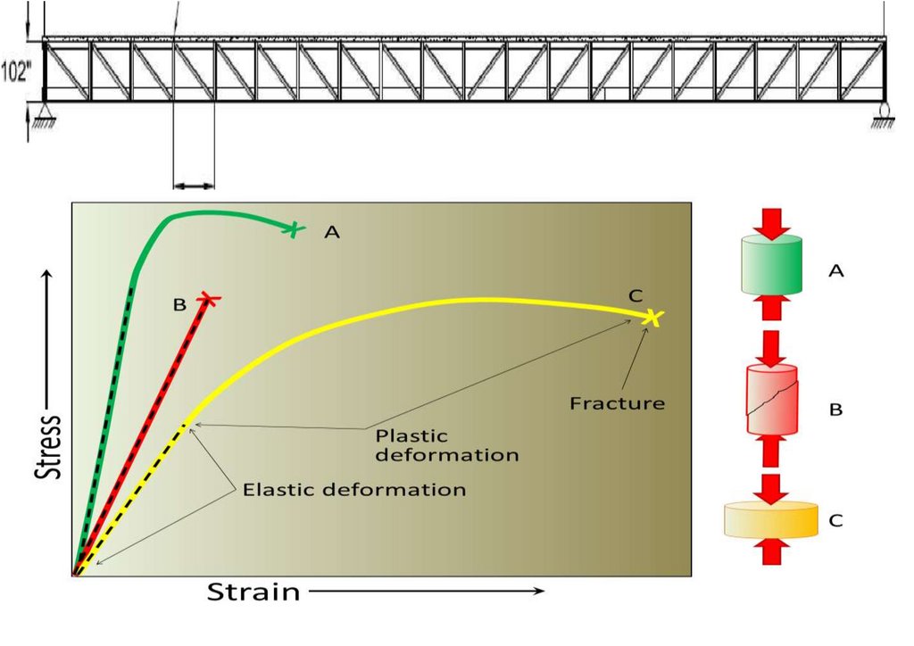
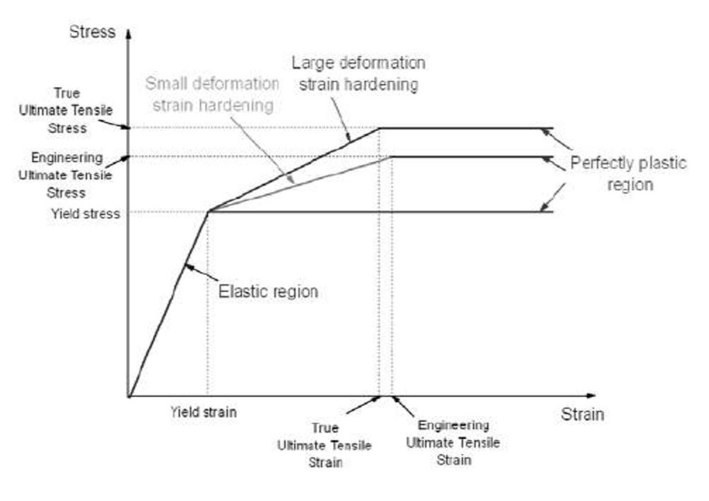
Figure 11 illustrates the bilinear stress-strain model. The material properties were adopted from the Bailey Bridge manual, AASHTO 2010, and GRSE of a similar bridge design with Young’s modulus of 2.0 × 10⁵ MPa and Poisson
ratio of 0.3 [14]. Moreover, it corresponded with previous studies [2,6,29]. In the present study, a linear analysis was performed to validate the model’s accuracy, and a nonlinear analysis for the bridge’s reliability. The superstructure was
set as SM490 steel with a yield strength of 325 MPa (
























































































































































 Строительство


