


 Электроника
Похожие презентации:


")


Washing Machine. Model:N09. Service Manual
1.
Washing MachineModel:N09
Service Manual
Note
Before service the unit, please read this manual first.
Contact with your service center if meet problem
2.
Contents1 PRECAUTION --------------------------------------------------------3
2 USER MANUAL -------------------------------------------------------7
3 WIRING DIAGRAM /PCB LAYOUT ----------------------------------8
4 FACTORY PATTEN DETECTION--------------------------------------10
5 MALFUNCTIONS CODES AND EXPLANATIONS -------------------13
6 TROUBLESHOOTING-------------------------------------------------16
7 CHECK POINT OF CIRCUIT-------------------------------------------26
8 UNPACKING WAYS OF MAIN PARTS -------------------------------27
9 SERVICE TOOLS-------------------------------------------------------34
2
3.
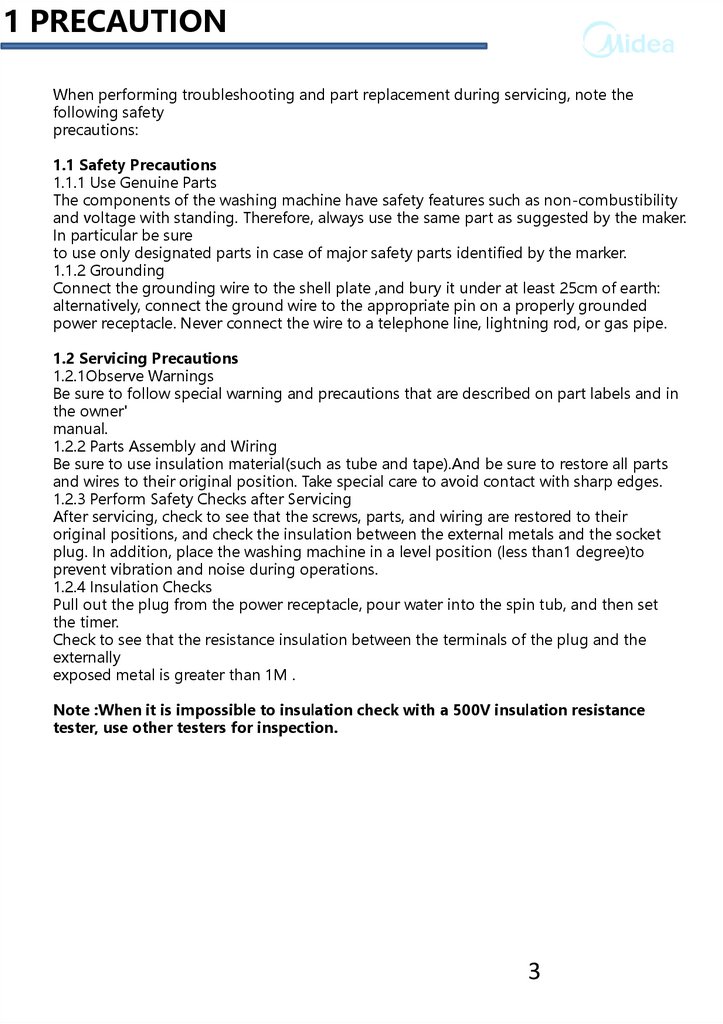
1 PRECAUTIONWhen performing troubleshooting and part replacement during servicing, note the
following safety
precautions:
1.1 Safety Precautions
1.1.1 Use Genuine Parts
The components of the washing machine have safety features such as non-combustibility
and voltage with standing. Therefore, always use the same part as suggested by the maker.
In particular be sure
to use only designated parts in case of major safety parts identified by the marker.
1.1.2 Grounding
Connect the grounding wire to the shell plate ,and bury it under at least 25cm of earth:
alternatively, connect the ground wire to the appropriate pin on a properly grounded
power receptacle. Never connect the wire to a telephone line, lightning rod, or gas pipe.
1.2 Servicing Precautions
1.2.1Observe Warnings
Be sure to follow special warning and precautions that are described on part labels and in
the owner'
manual.
1.2.2 Parts Assembly and Wiring
Be sure to use insulation material(such as tube and tape).And be sure to restore all parts
and wires to their original position. Take special care to avoid contact with sharp edges.
1.2.3 Perform Safety Checks after Servicing
After servicing, check to see that the screws, parts, and wiring are restored to their
original positions, and check the insulation between the external metals and the socket
plug. In addition, place the washing machine in a level position (less than1 degree)to
prevent vibration and noise during operations.
1.2.4 Insulation Checks
Pull out the plug from the power receptacle, pour water into the spin tub, and then set
the timer.
Check to see that the resistance insulation between the terminals of the plug and the
externally
exposed metal is greater than 1M .
Note :When it is impossible to insulation check with a 500V insulation resistance
tester, use other testers for inspection.
3
4.
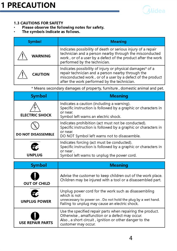
1 PRECAUTION1.3 CAUTIONS FOR SAFETY
Please observe the following notes for safety.
The symbols indicate as follows.
Symbol
Meaning
WARNING
Indicates possibility of death or serious injury of a repair
technician and a person nearby through the misconducted
work , or of a user by a defect of the product after the work
performed by the technician.
CAUTION
Indicates possibility of injury or physical damages* of a
repair technician and a person nearby through the
misconducted work , or of a user by a defect of the product
after the work performed by the technician.
* Means secondary damages of property, furniture , domestic animal and pet.
Symbol
ELECTRIC SHOCK
DO NOT DISASSEMBLE
UNPLUG
Symbol
OUT OF CHILD
Meaning
Indicates a caution (including a warning).
Specific instruction is followed by a graphic or characters in
or near.
Symbol left warns an electric shock.
Indicates prohibition (act must not be conducted).
Specific instruction is followed by a graphic or characters in
or near.
DO NOT Symbol left warns not to disassemble.
Indicates forcing (act must be conducted).
Specific instruction is followed by a graphic or characters in
or near .
Symbol left warns to unplug the power cord.
Meaning
Advise the customer to keep children out of the work place.
Children may be injured with a tool or a disassembled part.
Unplug power cord for the work such as disassembling
which is not
UNPLUG POWER
USE REPAIR PARTS
unnecessary to power on . Do not hold the plug by a wet hand.
Failing to unplug may cause an electric shock.
Use the specified repair parts when repairing the product.
Otherwise , amalfunction or a defect may occur.
Also , a short circuit , ignition or other danger to the
customer may occur.
4
5.
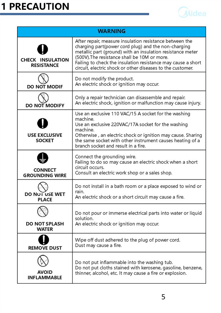
1 PRECAUTIONWARNING
CHECK INSULATION
RESISTANCE
DO NOT MODIF
DO NOT MODIFY
USE EXCLUSIVE
SOCKET
CONNECT
GROUNDING WIRE
DO NOT USE WET
PLACE
DO NOT SPLASH
WATER
REMOVE DUST
AVOID
INFLAMMABLE
After repair, measure insulation resistance between the
charging part(power cord plug) and the non-charging
metallic part (ground) with an insulation resistance meter
(500V).The resistance shall be 10M or more.
Failing to check the insulation resistance may cause a short
circuit, electric shock or other diseases to the customer.
Do not modify the product.
An electric shock or ignition may occur.
Only a repair technician can disassemble and repair.
An electric shock, ignition or malfunction may cause injury.
Use an exclusive 110 VAC/15 A socket for the washing
machine.
Use an exclusive 220VAC/17A socket for the washing
machine.
Otherwise , an electric shock or ignition may cause. Sharing
the same socket with other instrument causes heating of a
branch socket and result in a fire.
Connect the grounding wire.
Failing to do so may cause an electric shock when a short
circuit occurs.
Consult an electric work shop or a sales shop.
Do not install in a bath room or a place exposed to wind or
rain.
An electric shock or a short circuit may cause a fire.
Do not pour or immerse electrical parts into water or liquid
solution.
An electric shock or ignition may occur.
Wipe off dust adhered to the plug of power cord.
Dust may cause a fire.
Do not put inflammable into the washing tub.
Do not put cloths stained with kerosene, gasoline, benzene,
thinner, alcohol, etc. lt may cause a fire or explosion.
5
6.
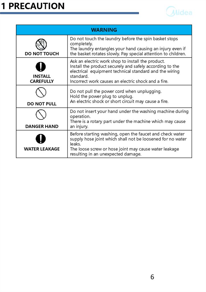
1 PRECAUTIONWARNING
DO NOT TOUCH
INSTALL
CAREFULLY
DO NOT PULL
DANGER HAND
WATER LEAKAGE
Do not touch the laundry before the spin basket stops
completely.
The laundry entangles your hand causing an injury even if
the basket rotates slowly. Pay special attention to children.
Ask an electric work shop to install the product.
Install the product securely and safely according to the
electrical equipment technical standard and the wiring
standard.
Incorrect work causes an electric shock and a fire.
Do not pull the power cord when unplugging.
Hold the power plug to unplug.
An electric shock or short circuit may cause a fire.
Do not insert your hand under the washing machine during
operation.
There is a rotary part under the machine which may cause
an injury.
Before starting washing, open the faucet and check water
supply hose joint which shall not be loosened for no water
leaks.
The loose screw or hose joint may cause water leakage
resulting in an unexpected damage.
6
7.
2 USER MANUALNOTE
Please check the user manual about the installation operation and spec etc.
7
8.
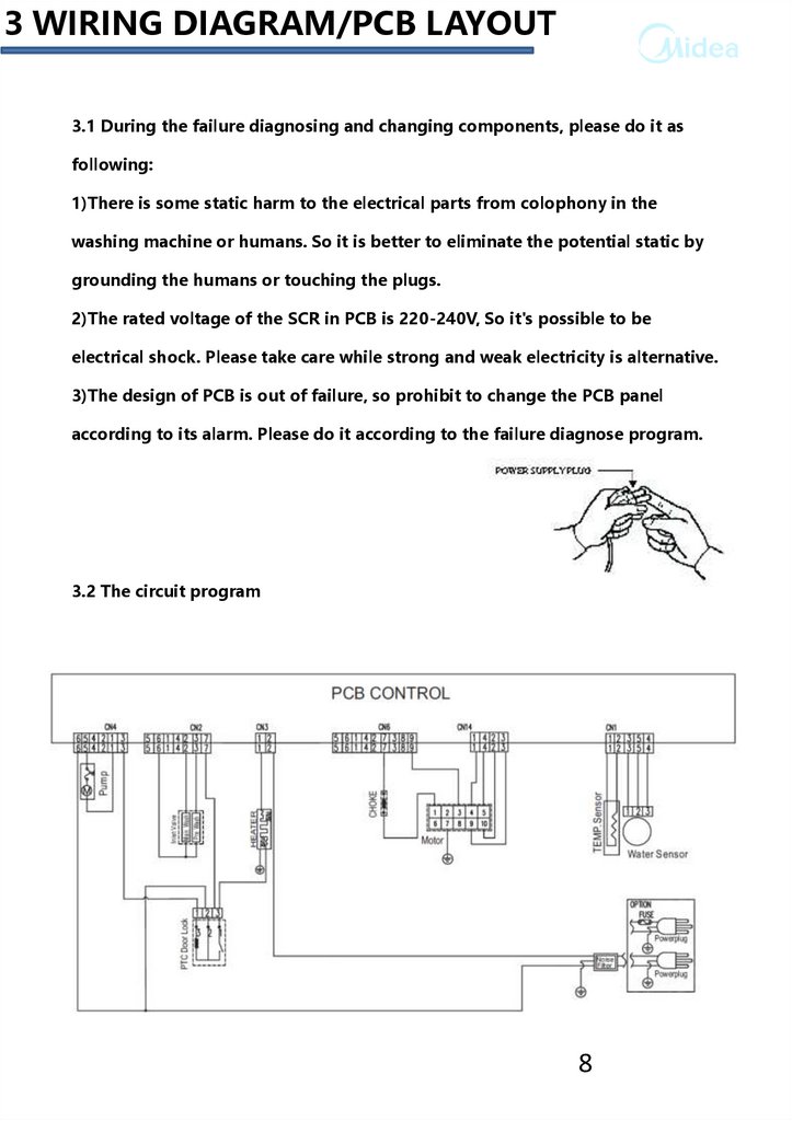
3 WIRING DIAGRAM/PCB LAYOUT3.1 During the failure diagnosing and changing components, please do it as
following:
1)There is some static harm to the electrical parts from colophony in the
washing machine or humans. So it is better to eliminate the potential static by
grounding the humans or touching the plugs.
2)The rated voltage of the SCR in PCB is 220-240V, So it's possible to be
electrical shock. Please take care while strong and weak electricity is alternative.
3)The design of PCB is out of failure, so prohibit to change the PCB panel
according to its alarm. Please do it according to the failure diagnose program.
3.2 The circuit program
8
9.
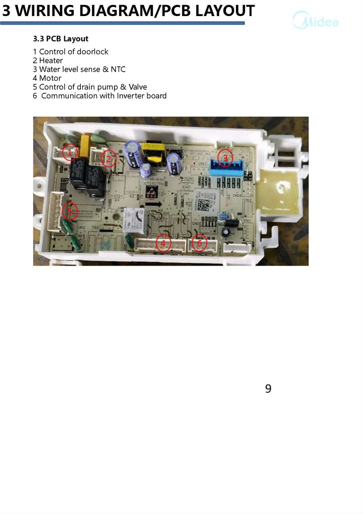
3 WIRING DIAGRAM/PCB LAYOUT3.3 PCB Layout
1 Control of doorlock
2 Heater
3 Water level sense & NTC
4 Motor
5 Control of drain pump & Valve
6 Communication with Inverter board
9
10.
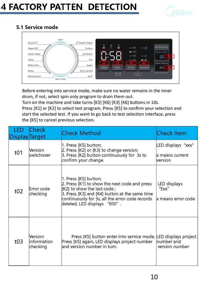
4 FACTORY PATTEN DETECTION5.1 Service mode
Before entering into service mode, make sure no water remains in the inner
drum, if not, select spin only program to drain them out.
Turn on the machine and take turns [K3] [K6] [K3] [K6] buttons in 10s.
Press [K1] or [K2] to select test program. Press [K5] to confirm your selection and
start the selected test. If you want to go back to test selection interface, press
the [K5] to cancel previous selection.
LED Check
Display Target
Check Method
Check Item
Version
switchover
1. Press [K5] button;
2. Press [K2] or [K3] to change version;
3. Press [K2] button continuously for 3s to
confirm your change.
LED displays“xxx”
t02
Error code
checking
1. Press [K5] button;
2. Press [K1] to show the next code and press LED displays
[K2] to show the last code ;
“Exx”
3. Press [K3] and [K4] button at the same time
continuously for 3s, all the error code records x means error code
deleted, LED displays “E00”.
t03
Version
information
checking
Press [K5] button enter into service mode. LED displays project
Press [K5] again, LED displays project number number and
and version number in turn.
version number
t01
x means current
version
10
11.
4 FACTORY PATTEN DETECTION5.1 Service mode
LED Check
Display Target
Check Method
Check Item
Press [K5] button to show the version
number. Press [K1] button, enter the display
UI Checking test, the whole LED displays flashes, then
enter the button test, press all the buttons,
LED displays corresponding number.
The whole LED
displays flashes.
t05
Drain-pump
Press [K5] button to drain out all the
checking
remaining water.
If all water drained
out, LED displays
“god”, After 20s,
if there is still water
remains in it,
LED displays “FP”,
t06
Pressure
switch
checking
t07
Water
Press [K5] button to activate the main
temperature
inlet valve and get the water lever to heating LED displays the
sensor and
level then turn on the heater and 5 mins later current temperature.
heater
turned off automatically.
checking
t04
t08
Inlet valve
checking
Press [K5] button to activate inlet valve.
The inlet valve enters the overflow water level LED displays the
to display the current water level frequency in current water level.
real time.
1. Press [K5] button;
2. Press [K1] button, switch off the main wash
inlet valve , switch on prewash valve for 5s;
LED displays the
3. Press [K1] button to switch on main wash corresponding
and prewash valve and get the water lever to status.
setting level;
4. Press [K5] button to drain out the water.
11
12.
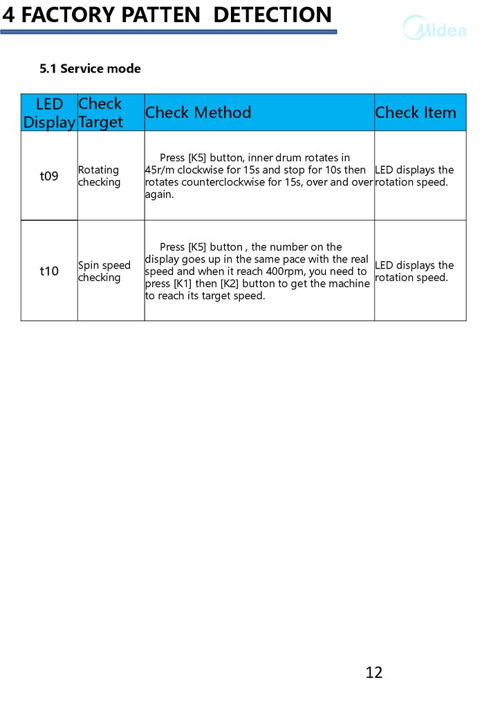
4 FACTORY PATTEN DETECTION5.1 Service mode
LED Check
Display Target
t09
t10
Check Method
Check Item
Rotating
checking
Press [K5] button, inner drum rotates in
45r/m clockwise for 15s and stop for 10s then LED displays the
rotates counterclockwise for 15s, over and over rotation speed.
again.
Spin speed
checking
Press [K5] button , the number on the
display goes up in the same pace with the real
LED displays the
speed and when it reach 400rpm, you need to
rotation speed.
press [K1] then [K2] button to get the machine
to reach its target speed.
12
13.
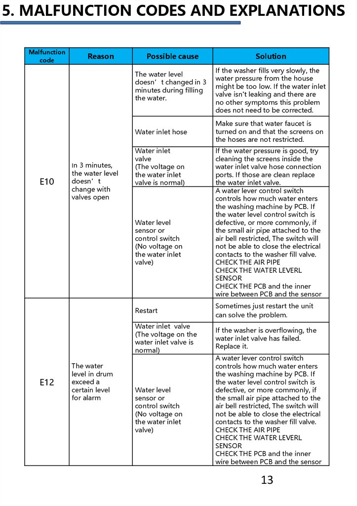
5. MALFUNCTION CODES AND EXPLANATIONSMalfunction
code
Reason
Possible cause
The water level
doesn’t changed in 3
minutes during filling
the water.
Water inlet hose
E10
In 3 minutes,
the water level
doesn’t
change with
valves open
Water inlet
valve
(The voltage on
the water inlet
valve is normal)
Water level
sensor or
control switch
(No voltage on
the water inlet
valve)
E12
The water
level in drum
exceed a
certain level
for alarm
Solution
If the washer fills very slowly, the
water pressure from the house
might be too low. If the water inlet
valve isn't leaking and there are
no other symptoms this problem
does not need to be corrected.
Make sure that water faucet is
turned on and that the screens on
the hoses are not restricted.
If the water pressure is good, try
cleaning the screens inside the
water inlet valve hose connection
ports. If those are clean replace
the water inlet valve.
A water lever control switch
controls how much water enters
the washing machine by PCB. If
the water level control switch is
defective, or more commonly, if
the small air pipe attached to the
air bell restricted, The switch will
not be able to close the electrical
contacts to the washer fill valve.
CHECK THE AIR PIPE
CHECK THE WATER LEVERL
SENSOR
CHECK THE PCB and the inner
wire between PCB and the sensor
Restart
Sometimes just restart the unit
can solve the problem.
Water inlet valve
(The voltage on the
water inlet valve is
normal)
If the washer is overflowing, the
water inlet valve has failed.
Replace it.
Water level
sensor or
control switch
(No voltage on
the water inlet
valve)
A water lever control switch
controls how much water enters
the washing machine by PCB. If
the water level control switch is
defective, or more commonly, if
the small air pipe attached to the
air bell restricted, The switch will
not be able to close the electrical
contacts to the washer fill valve.
CHECK THE AIR PIPE
CHECK THE WATER LEVERL
SENSOR
CHECK THE PCB and the inner
wire between PCB and the sensor
13
14.
5. MALFUNCTION CODES AND EXPLANATIONSDrain hose
If the washer won't drain water
check the drain hose. Be sure the
hose did not get kinked behind
the washer. Also, remove the
hose from the pump and check it
for obstructions.
pump
If the washer won't drain water
the drain pump might be
defective. It's also common for a
small sock or other article of
clothing to get caught in the drain
pump or in the drain hose. Check
both for an obstruction before
replacing the pump.
PCB
Check the PCB
Door lock
Check the door hook and the door
lock to get correct location.
PCB
If the washer door won't unlock
the problem might be the main
The PCB. This is not common.
Check the inner wire between the
PCB and the door lock.
E33
The PCB can not
detect the signal
of the water level
sensor.
Water level sensor
Check the water level sensor
Check the PCB the inner
wire between PCB and the sensor
E34
Temperature
sensor fail
The temperature
sensor(NTC) get
broken
Check the NTC
E60
1.Check the PCB and the motor
The motor don’t The motor don’t drive
2.Check the motor communicate
drive
for 5 times
wire
E21
E30
In 3 minutes,
the water level
doesn’t
change with
pump started
Door can’t be
unlocked with
over 3 time’s
fail.
14
15.
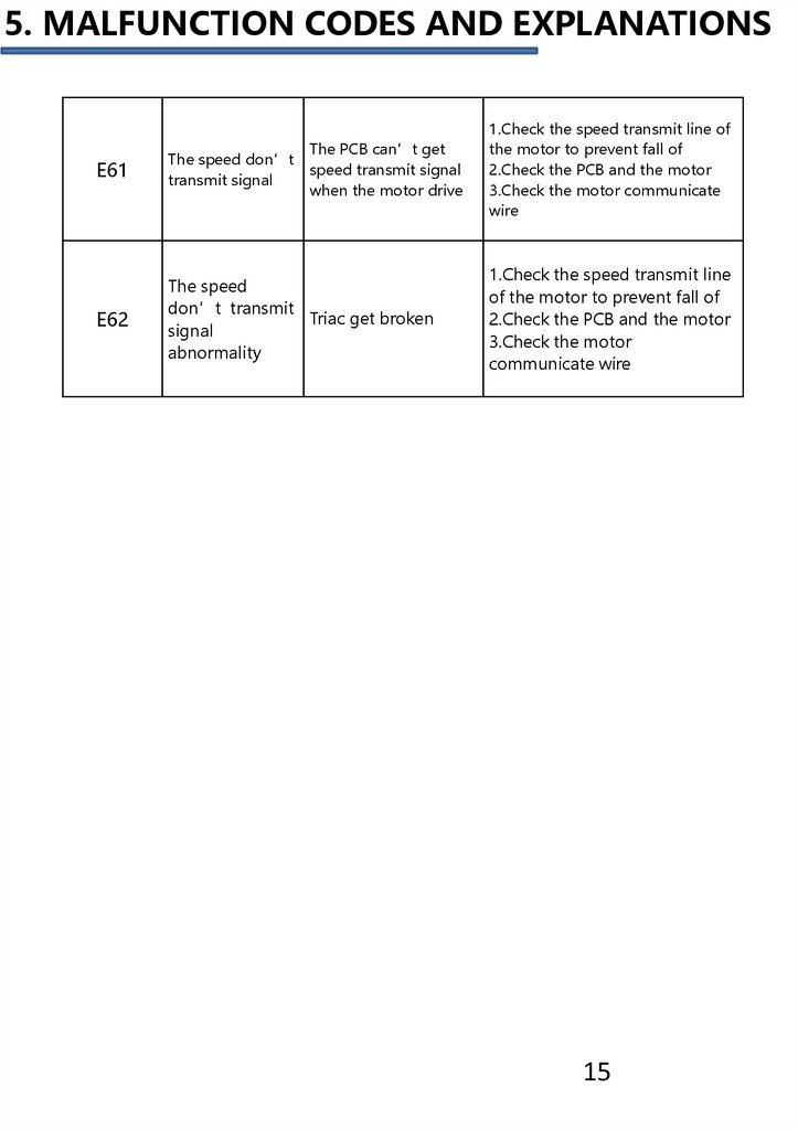
5. MALFUNCTION CODES AND EXPLANATIONSThe PCB can’t get
speed transmit signal
when the motor drive
E61
The speed don’t
transmit signal
E62
The speed
don’t transmit
Triac get broken
signal
abnormality
1.Check the speed transmit line of
the motor to prevent fall of
2.Check the PCB and the motor
3.Check the motor communicate
wire
1.Check the speed transmit line
of the motor to prevent fall of
2.Check the PCB and the motor
3.Check the motor
communicate wire
15
16.
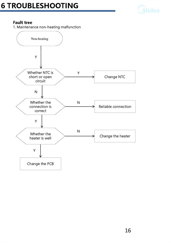
6 TROUBLESHOOTINGFault tree
1. Maintenance non-heating malfunction
Non-heating
Y
Whether NTC is
short or open
circuit
Y
Change NTC
N
Whether the
connection is
correct
N
Reliable connection
Y
Whether the
heater is well
N
Change the heater
Y
Change the PCB
16
17.
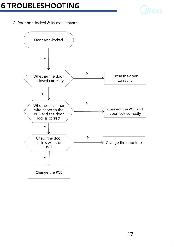
6 TROUBLESHOOTING2. Door non-locked & its maintenance
Door non-locked
Y
Whether the door
is closed correctly
N
Close the door
correctly
Y
Whether the inner
wire between the
PCB and the door
lock is correct
N
Connect the PCB and
door lock correctly
Y
Check the door
lock is well or
not
N
Change the door lock
Y
Change the PCB
17
18.
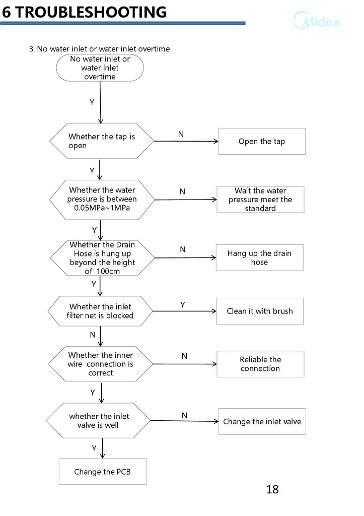
6 TROUBLESHOOTING3. No water inlet or water inlet overtime
No water inlet or
water inlet
overtime
Y
Whether the tap is
open
N
Open the tap
Y
Whether the water
pressure is between
0.05MPa~1MPa
N
Wait the water
pressure meet the
standard
Y
Whether the Drain
Hose is hung up
beyond the height
of 100cm
N
Hang up the drain
hose
Y
Whether the inlet
filter net is blocked
Y
Clean it with brush
N
Whether the inner
wire connection is
correct
N
Reliable the
connection
Y
whether the inlet
valve is well
N
Change the inlet valve
Y
Change the PCB
18
19.
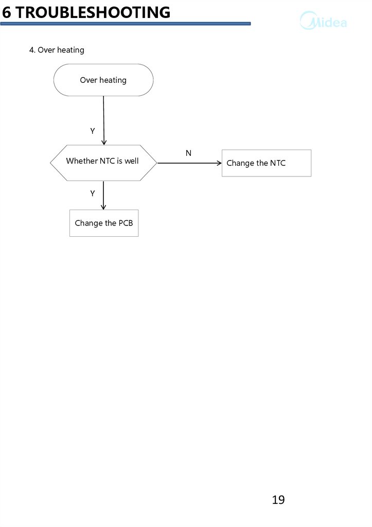
6 TROUBLESHOOTING4. Over heating
Over heating
Y
circuit open
circuit
Whether
NTC is well
N
Change the NTC
Y
Change the PCB
19
20.
6 TROUBLESHOOTING5. Maintenance of non-drain or drain exceed the setting time
Non-drain or
overtime drain
Y
Whether the Drain
Hose is hung up
beyond the height
of 100cm
N
Hang up the drain
hose
Y
Whether the
pump is blocked
Y
Clean the filter
N
Whether the
pump is well
N
Change the
drain pump
N
Change the PCB
20
21.
6 TROUBLESHOOTING6. Water inlet overflow malfunction maintenance
Water inlet overflow
Y
whether the inlet
valve is well
N
Change the inlet valve
Y
Whether the
pressure switch is
well
N
Change pressure
switch
Y
Change the PCB
21
22.
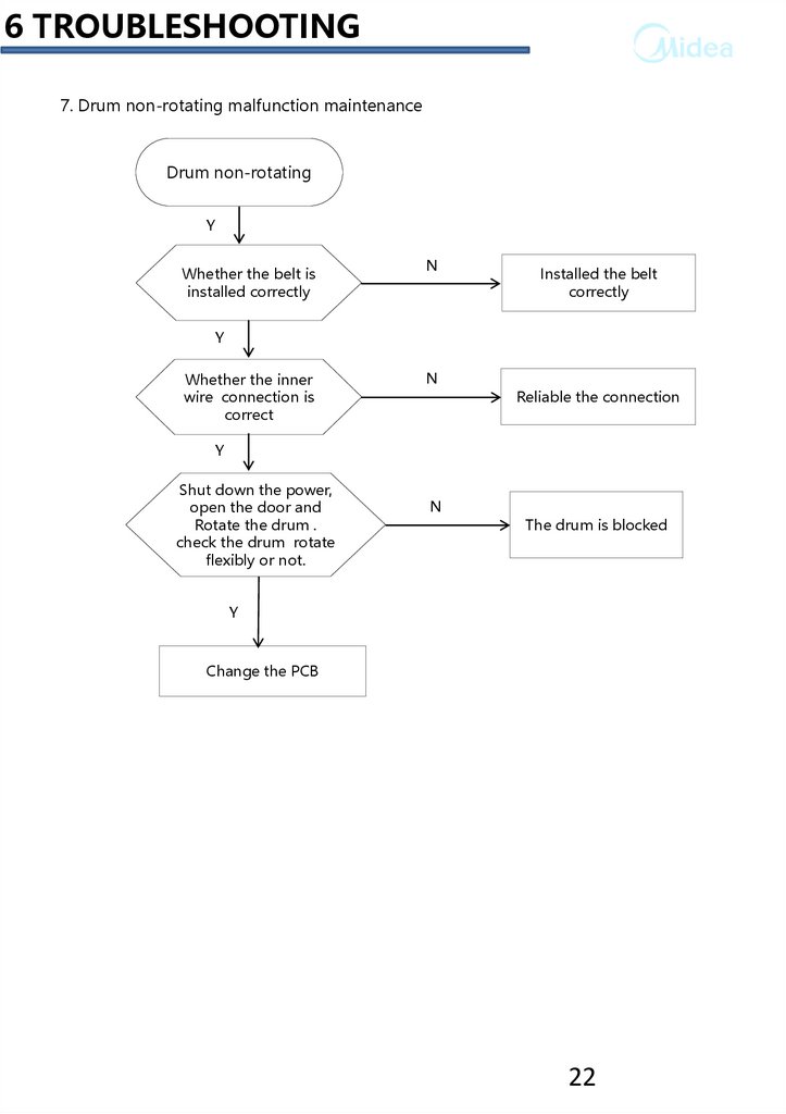
6 TROUBLESHOOTING7. Drum non-rotating malfunction maintenance
Drum non-rotating
Y
Whether the belt is
installed correctly
N
Installed the belt
correctly
Y
Whether the inner
wire connection is
correct
N
Reliable the connection
Y
Shut down the power,
open the door and
Rotate the drum .
check the drum rotate
flexibly or not.
N
The drum is blocked
Y
Change the PCB
22
23.
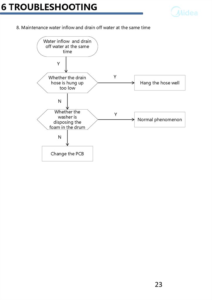
6 TROUBLESHOOTING8. Maintenance water inflow and drain off water at the same time
Water inflow and drain
off water at the same
time
Y
Whether the drain
hose is hung up
too low
Y
Hang the hose well
N
Whether the
washer is
disposing the
foam in the drum
Y
Normal phenomenon
N
Change the PCB
23
24.
6 TROUBLESHOOTINGMalfunction and solution
Description
Solution
The washing machine
does not work
Close the washing machine's door.
Water leakage
Correctly connect the inlet water pipe.
The speed of the clothes is
Reload and distribute the laundry evenly in the drum.
abnormal
There is the peculiar smell
in the washing machine
Run a Self clean(Drum clean) cycle without any clothes.
No water is visible in the
drum
No fault-water is under the visible area.
There is the remaining
No fault- the effect of the softener will not be affected.
water in the softener's box
The remaining detergent
is left on the clothes
The water-fast component of the non-phosphorus.
detergent will be left on the clothes to form the line scale.
Please select 【rinse】 or【 spin 】programme or brush
away the fleck with the brush when the clothes is dried.
The washing machine
does not fill
Open the water tap.
Check the selection of the procedure.
Check the water.
Pressure to see if the water pressure is insufficient.
Put through the feed-water.
Close the washing machine's door.
To check it the inlet water pipe is bent or blocked.
The washing machine fills
and empties at the same
time.
Make sure the end of the drainage pipe to be higher.
Check if the drainage pipe and sewage have been sealed,
if they have been, there will be the poor ventilation to
cause the sip hon age effect.
No drainage of the
washing machine
Check if the drainage pump is blocked.
Check if the drainage pipe is bent or blocked.
Check the height of the drainage nozzle, make sure it
is0.6-1 meter from the bottom of the washing machine.
24
25.
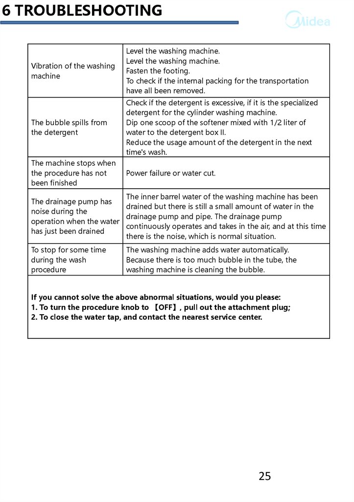
6 TROUBLESHOOTINGVibration of the washing
machine
Level the washing machine.
Level the washing machine.
Fasten the footing.
To check if the internal packing for the transportation
have all been removed.
The bubble spills from
the detergent
Check if the detergent is excessive, if it is the specialized
detergent for the cylinder washing machine.
Dip one scoop of the softener mixed with 1/2 liter of
water to the detergent box II.
Reduce the usage amount of the detergent in the next
time's wash.
The machine stops when
the procedure has not
been finished
Power failure or water cut.
The inner barrel water of the washing machine has been
The drainage pump has
drained but there is still a small amount of water in the
noise during the
drainage pump and pipe. The drainage pump
operation when the water
continuously operates and takes in the air, and at this time
has just been drained
there is the noise, which is normal situation.
To stop for some time
during the wash
procedure
The washing machine adds water automatically.
Because there is too much bubble in the tube, the
washing machine is cleaning the bubble.
If you cannot solve the above abnormal situations, would you please:
1. To turn the procedure knob to 【OFF】, pull out the attachment plug;
2. To close the water tap, and contact the nearest service center.
25
26.
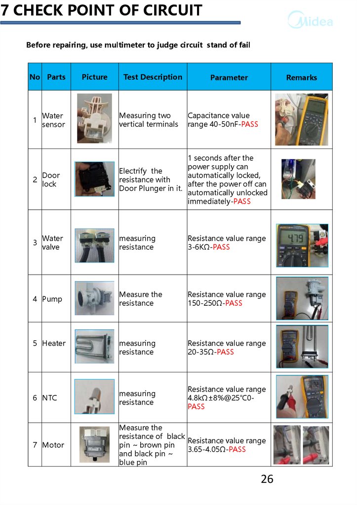
7 CHECK POINT OF CIRCUITBefore repairing, use multimeter to judge circuit stand of fail
No Parts
Picture
Test Description
Parameter
Remarks
Water
sensor
Measuring two
vertical terminals
2
Door
lock
1 seconds after the
power supply can
Electrify the
automatically locked,
resistance with
after the power off can
Door Plunger in it.
automatically unlocked
immediately-PASS
3
Water
valve
measuring
resistance
Resistance value range
3-6KΩ-PASS
4 Pump
Measure the
resistance
Resistance value range
150-250Ω-PASS
measuring
resistance
Resistance value range
20-35Ω-PASS
6 NTC
measuring
resistance
Resistance value range
4.8kΩ±8%@25℃0PASS
7 Motor
Measure the
resistance of black
Resistance value range
pin ~ brown pin
3.65-4.05Ω-PASS
and black pin ~
blue pin
1
5 Heater
Capacitance value
range 40-50nF-PASS
26
27.
8 UNPACKING WAYS OF MAIN PARTSUNPACKING WAYS OF MAIN PARTS
1. Undo the back cover
2. Undo top cover
3. Undo the control panel and PCB
4. Undo the door assembly
5. Undo the front plate
6. Undo the detergent box
7. Undo the inlet valve
8. Undo the pressure switch
9. Undo the drain pump
10. Undo the pulley and motor
11. Undo the absorber pin from the cabinet
12.Undo the drum tub assembly
13. Undo the absorber pin from the drum
14.Undo the heater and NTC
27
28.
8 UNPACKING WAYS OF MAIN PARTSOperation
Picture
1. Undo the back cover
Undo four screws fit
between back plate and
cabinet, and then pull out.
2. Undo the top cover
I. Undo 2 screws fit back
Cabinet.
II. Push back the top cover
15mm until it leaves away
from the control panel,
and then take it down.
3. Undo the control panel
and PCB
I. Departing the top cover
II. Draw out the detergent
drawer.
III. Loosen two screws fit
on the control panel .
IV. Loosen two screws fit
on the control panel.
V. Take out the control
Panel inclined from the
panel .
VI. Extract the cycle select
knob
VII. Pull out the wire and
press the buckle to take
out the PCB.
28
29.
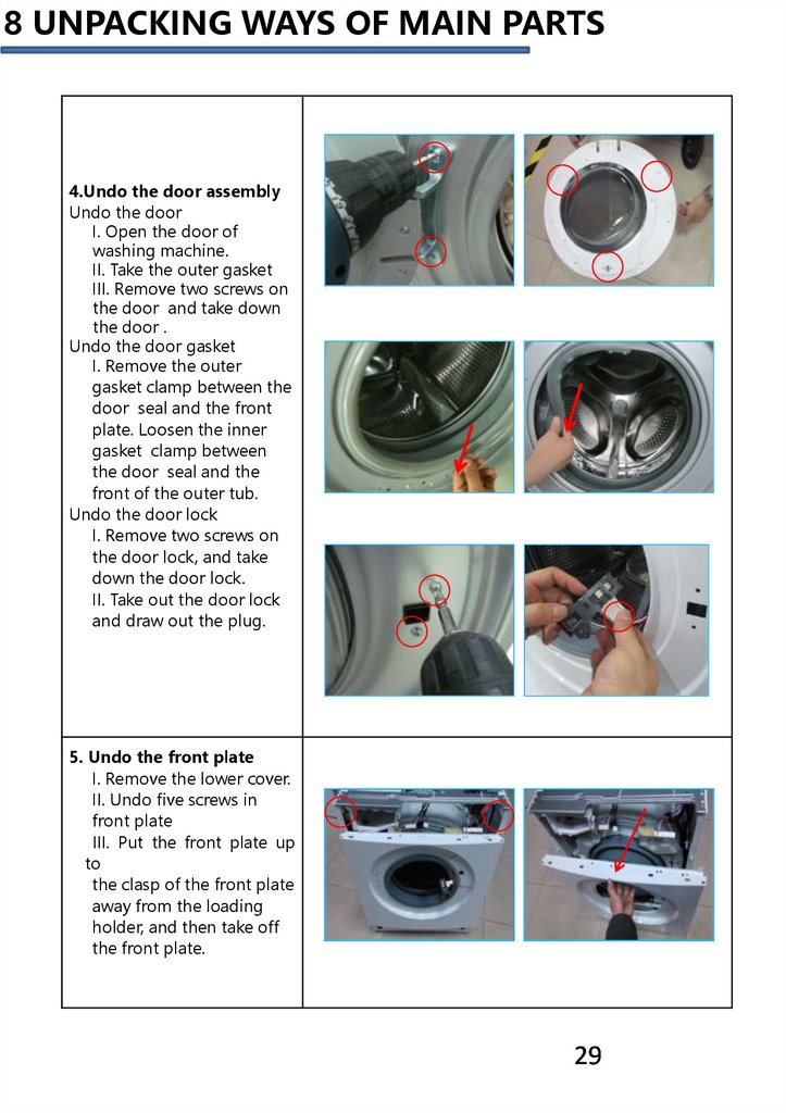
8 UNPACKING WAYS OF MAIN PARTS4.Undo the door assembly
Undo the door
I. Open the door of
washing machine.
II. Take the outer gasket
III. Remove two screws on
the door and take down
the door .
Undo the door gasket
I. Remove the outer
gasket clamp between the
door seal and the front
plate. Loosen the inner
gasket clamp between
the door seal and the
front of the outer tub.
Undo the door lock
I. Remove two screws on
the door lock, and take
down the door lock.
II. Take out the door lock
and draw out the plug.
5. Undo the front plate
I. Remove the lower cover.
II. Undo five screws in
front plate
III. Put the front plate up
to
the clasp of the front plate
away from the loading
holder, and then take off
the front plate.
29
30.
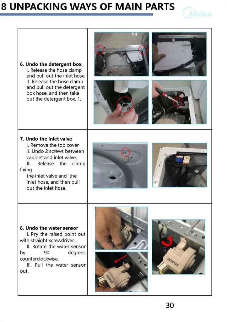
8 UNPACKING WAYS OF MAIN PARTS6. Undo the detergent box
I. Release the hose clamp
and pull out the inlet hose.
II. Release the hose clamp
and pull out the detergent
box hose, and then take
out the detergent box. 1.
7. Undo the inlet valve
I. Remove the top cover
II. Undo 2 screws between
cabinet and inlet valve.
III. Release the clamp
fixing
the inlet valve and the
inlet hose, and then pull
out the inlet hose.
8. Undo the water sensor
I. Pry the raised point out
with straight screwdriver .
II. Rotate the water sensor
by
90
degrees
counterclockwise.
III. Pull the water sensor
out.
30
31.
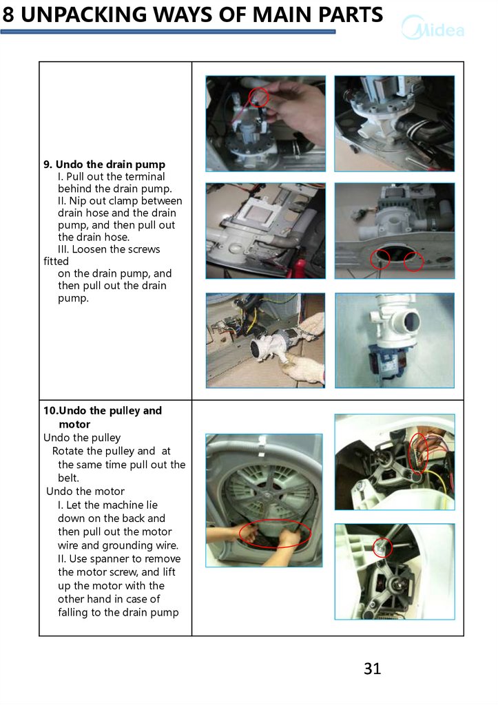
8 UNPACKING WAYS OF MAIN PARTS9. Undo the drain pump
I. Pull out the terminal
behind the drain pump.
II. Nip out clamp between
drain hose and the drain
pump, and then pull out
the drain hose.
III. Loosen the screws
fitted
on the drain pump, and
then pull out the drain
pump.
10.Undo the pulley and
motor
Undo the pulley
Rotate the pulley and at
the same time pull out the
belt.
Undo the motor
I. Let the machine lie
down on the back and
then pull out the motor
wire and grounding wire.
II. Use spanner to remove
the motor screw, and lift
up the motor with the
other hand in case of
falling to the drain pump
31
32.
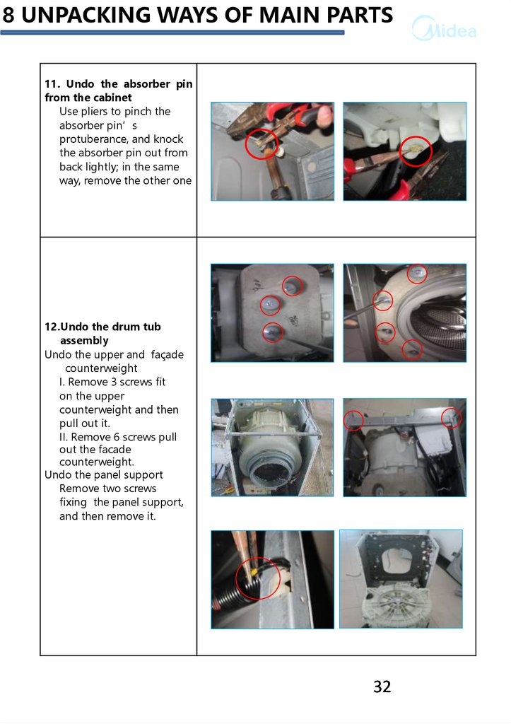
8 UNPACKING WAYS OF MAIN PARTS11. Undo the absorber pin
from the cabinet
Use pliers to pinch the
absorber pin’s
protuberance, and knock
the absorber pin out from
back lightly; in the same
way, remove the other one
12.Undo the drum tub
assembly
Undo the upper and façade
counterweight
I. Remove 3 screws fit
on the upper
counterweight and then
pull out it.
II. Remove 6 screws pull
out the facade
counterweight.
Undo the panel support
Remove two screws
fixing the panel support,
and then remove it.
32
33.
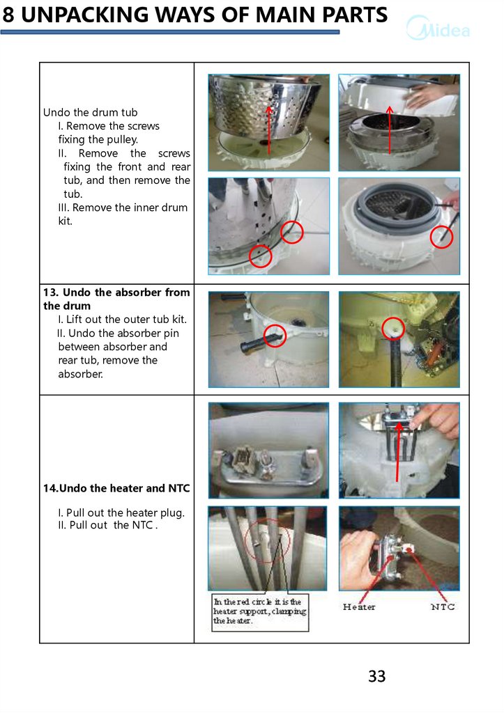
8 UNPACKING WAYS OF MAIN PARTSUndo the drum tub
I. Remove the screws
fixing the pulley.
II. Remove the screws
fixing the front and rear
tub, and then remove the
tub.
III. Remove the inner drum
kit.
13. Undo the absorber from
the drum
I. Lift out the outer tub kit.
II. Undo the absorber pin
between absorber and
rear tub, remove the
absorber.
14.Undo the heater and NTC
I. Pull out the heater plug.
II. Pull out the NTC .
33
34.
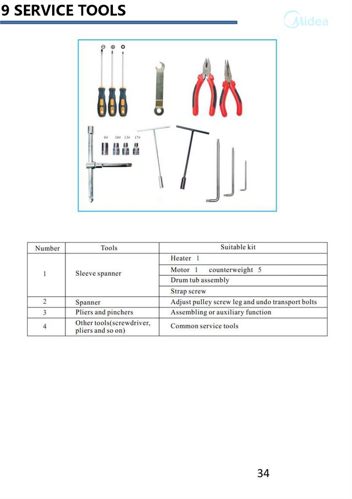
9 SERVICE TOOLS34