


 Электроника
Похожие презентации:

")


NV75K5541RS Training Manual
1.
NV75K5541RS Training ManualJan. 2016
System Cooking Business Team
1
2.
ContentsAgenda
I.
Precaution
II.
Feature and Specifications
III.
Installation
IV.
Function
V.
Service Information
VI.
Disassembly and Assembly
VII.
Trouble shooting
VIII.
Circuit Diagram
IX.
Wiring Diagram
X.
Nomenclature
XI.
Q&A
2
3.
Precaution1-1. Safety Precaution
Follow these special safety precautions during repair or inspection.
1. All repairs should be done in accordance with the procedures described in this manual.
This product complies with Federal Performance Standard 21 CFR Subchapter J(DHHS).
2. Check all grounds.
3. Do not power the OVEN from a “2 - prong” AC cord. Be sure that all of the built – in
protective devices are replaced. Restore any missing protective shields.
4. When reinstalling the chassis and its assemblies, be sure to restore all protective
devices including nonmetallic control knobs and compartment covers.
5. Make sure that there are no cabinet openings through which people --particularly
children --might insert objects and contact dangerous voltages.
6. Service technicians should remove their watches while repairing an OVEN.
7. Design Alteration Warning:
Use exact replacement parts only, i.e., only those that are specified in the drawings and
parts lists of this manual. Never alter or add to the mechanical or electrical design of the
OVEN. Any design changes or additions will void the manufacturer’s warranty.
Always unplug the unit’s AC power cord from the AC power source before attempting to
remove or reinstall any component or assembly.
4.
Precaution1-1. Safety Precaution
8. Never defeat any of the B+ voltage interlocks. Do not apply AC power to the unit (or any
of its assemblies) unless all solid-state heat sinks are correctly installed.
9. Some semiconductor (“solid state”) devices are easily damaged by static electricity.
Such components are called Electro statically Sensitive Devices (ESDs). Examples
include integrated circuits and field effect transistors. Immediately before handling any
semiconductor components or assemblies, drain the electrostatic charge from your body
by touching a known earth ground.
Precaution
10. Always connect a test instrument’s ground lead to the instrument chassis ground
before connecting the positive lead; always remove the instrument’s ground lead last.
11. Use replacement components that have the same ratings, especially for flame
resistance and dielectric strength specifications. A replacement part that does not have
the same safety characteristics as the original might create shock, re or other hazards.
NOTE: Connect the oven to a 20 A. When connecting the oven to a 15 A, make sure that circuit
breaker can operate.
12. Never touch any circuit wiring with your hand nor with uninsulated tool during operation.
5.
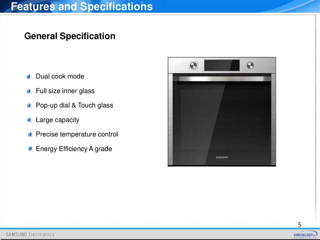
Features and SpecificationsGeneral Specification
Dual cook mode
Full size inner glass
Pop-up dial & Touch glass
Large capacity
Precise temperature control
Energy Efficiency A grade
5
6.
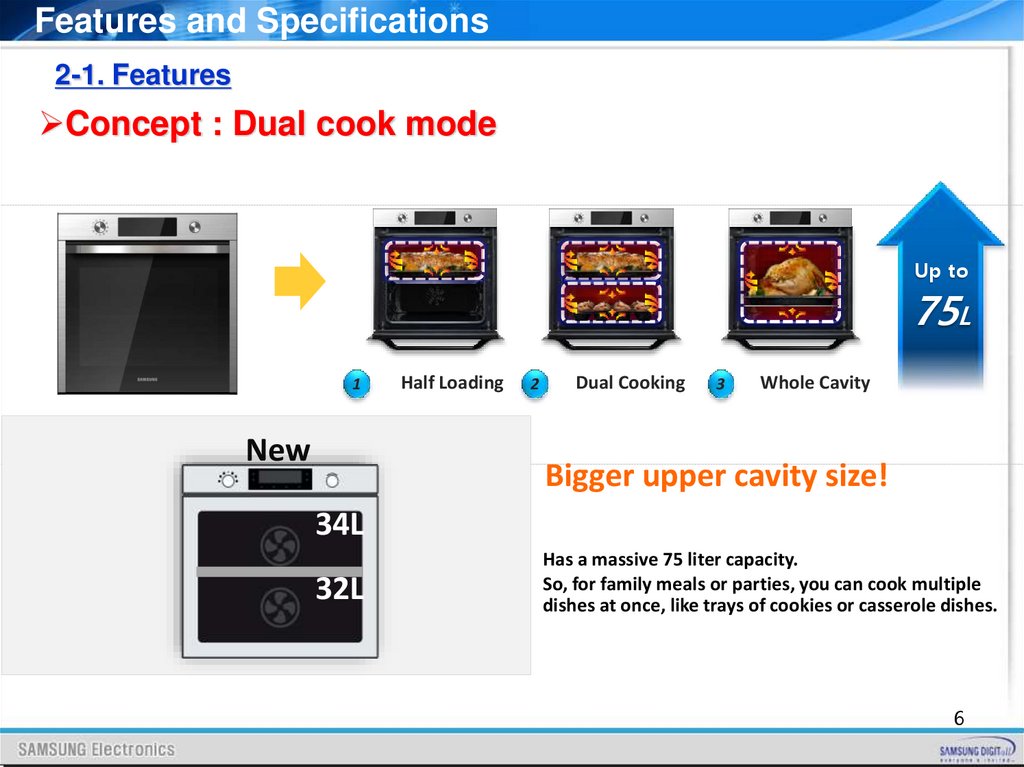
Features and Specifications2-1. Features
Concept : Dual cook mode
Up to
75L
1
New
Half Loading
2
Dual Cooking
3
Whole Cavity
Bigger upper cavity size!
34L
32L
Has a massive 75 liter capacity.
So, for family meals or parties, you can cook multiple
dishes at once, like trays of cookies or casserole dishes.
6
7.
Features and Specifications2-2. Features
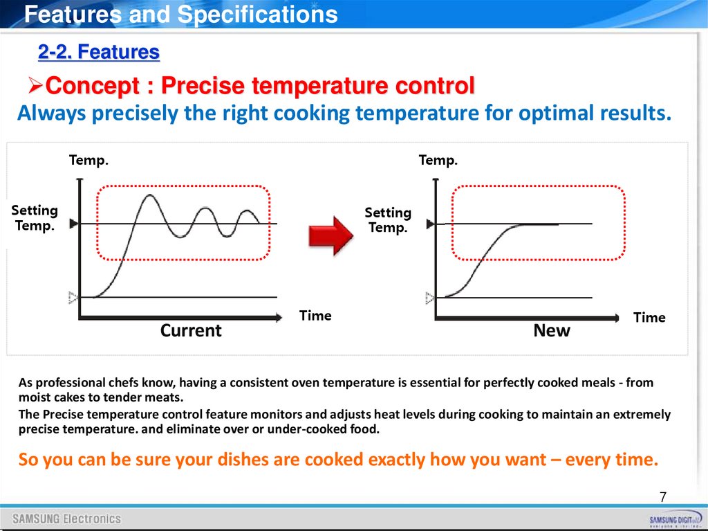
Concept : Precise temperature control
Always precisely the right cooking temperature for optimal results.
Temp.
Temp.
Setting
Temp.
Setting
Temp.
Current
Time
New
Time
As professional chefs know, having a consistent oven temperature is essential for perfectly cooked meals - from
moist cakes to tender meats.
The Precise temperature control feature monitors and adjusts heat levels during cooking to maintain an extremely
precise temperature. and eliminate over or under-cooked food.
So you can be sure your dishes are cooked exactly how you want – every time.
7
8.
Features and Specifications2-3. Control Panel
8
9.
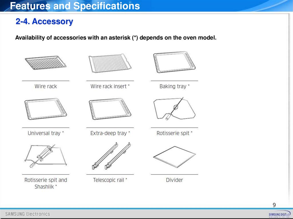
Features and Specifications2-4. Accessory
Availability of accessories with an asterisk (*) depends on the oven model.
9
10.
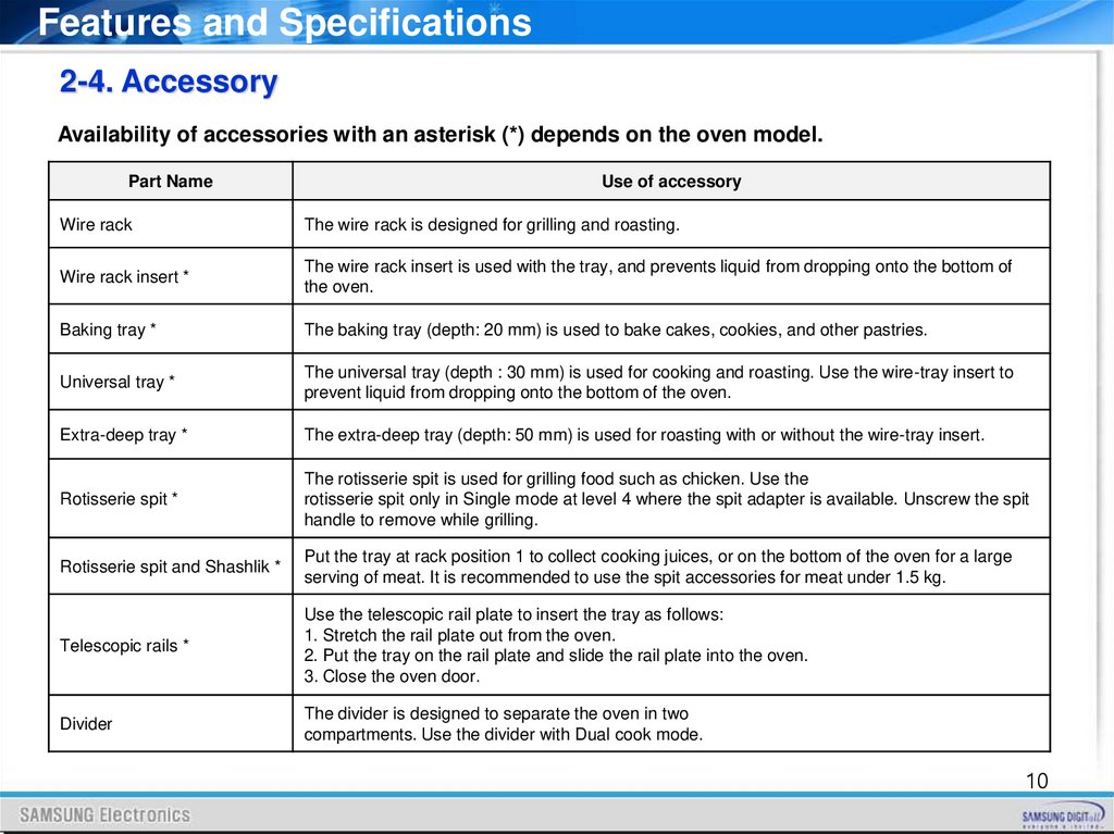
Features and Specifications2-4. Accessory
Availability of accessories with an asterisk (*) depends on the oven model.
Part Name
Use of accessory
Wire rack
The wire rack is designed for grilling and roasting.
Wire rack insert *
The wire rack insert is used with the tray, and prevents liquid from dropping onto the bottom of
the oven.
Baking tray *
The baking tray (depth: 20 mm) is used to bake cakes, cookies, and other pastries.
Universal tray *
The universal tray (depth : 30 mm) is used for cooking and roasting. Use the wire-tray insert to
prevent liquid from dropping onto the bottom of the oven.
Extra-deep tray *
The extra-deep tray (depth: 50 mm) is used for roasting with or without the wire-tray insert.
Rotisserie spit *
The rotisserie spit is used for grilling food such as chicken. Use the
rotisserie spit only in Single mode at level 4 where the spit adapter is available. Unscrew the spit
handle to remove while grilling.
Rotisserie spit and Shashlik *
Put the tray at rack position 1 to collect cooking juices, or on the bottom of the oven for a large
serving of meat. It is recommended to use the spit accessories for meat under 1.5 kg.
Telescopic rails *
Use the telescopic rail plate to insert the tray as follows:
1. Stretch the rail plate out from the oven.
2. Put the tray on the rail plate and slide the rail plate into the oven.
3. Close the oven door.
Divider
The divider is designed to separate the oven in two
compartments. Use the divider with Dual cook mode.
10
11.
Features and Specifications2-4. Accessory
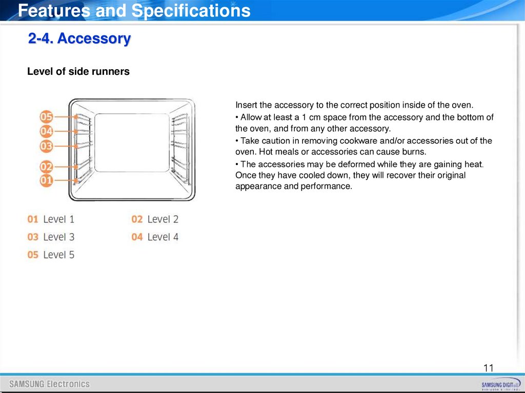
Level of side runners
Insert the accessory to the correct position inside of the oven.
• Allow at least a 1 cm space from the accessory and the bottom of
the oven, and from any other accessory.
• Take caution in removing cookware and/or accessories out of the
oven. Hot meals or accessories can cause burns.
• The accessories may be deformed while they are gaining heat.
Once they have cooled down, they will recover their original
appearance and performance.
11
12.
Features and Specifications2-5. Specifications
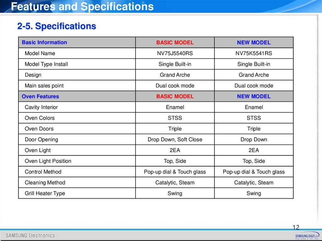
Basic Information
BASIC MODEL
NEW MODEL
Model Name
NV75J5540RS
NV75K5541RS
Model Type Install
Single Built-in
Single Built-in
Design
Grand Arche
Grand Arche
Main sales point
Dual cook mode
Dual cook mode
Oven Features
BASIC MODEL
NEW MODEL
Cavity Interior
Enamel
Enamel
Oven Colors
STSS
STSS
Oven Doors
Triple
Triple
Door Opening
Drop Down, Soft Close
Drop Down
Oven Light
2EA
2EA
Top, Side
Top, Side
Control Method
Pop-up dial & Touch glass
Pop-up dial & Touch glass
Cleaning Method
Catalytic, Steam
Catalytic, Steam
Grill Heater Type
Swing
Swing
Oven Light Position
12
13.
Features and SpecificationsContents2-5. Specifications
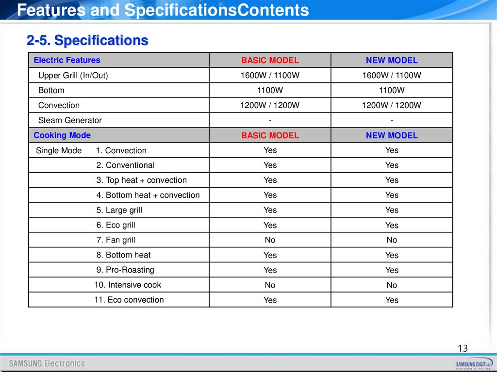
Electric Features
BASIC MODEL
NEW MODEL
Upper Grill (In/Out)
1600W / 1100W
1600W / 1100W
1100W
1100W
1200W / 1200W
1200W / 1200W
-
-
BASIC MODEL
NEW MODEL
1. Convection
Yes
Yes
2. Conventional
Yes
Yes
3. Top heat + convection
Yes
Yes
4. Bottom heat + convection
Yes
Yes
5. Large grill
Yes
Yes
6. Eco grill
Yes
Yes
7. Fan grill
No
No
8. Bottom heat
Yes
Yes
9. Pro-Roasting
Yes
Yes
10. Intensive cook
No
No
11. Eco convection
Yes
Yes
Bottom
Convection
Steam Generator
Cooking Mode
Single Mode
13
14.
Features and SpecificationsContents2-5. Specifications
Cooking Mode
Upper Mode
Lower Mode
BASIC MODEL
NEW MODEL
1. Convection
Yes
Yes
2. Top heat + convection
Yes
Yes
3. Large grill
Yes
Yes
4. Eco grill
No
No
5. Fan grill
No
No
1. Convection
Yes
Yes
2. Bottom heat + convection
Yes
Yes
3. Bottom heat
Yes
Yes
14
15.
Features and Specifications2-5. Specifications
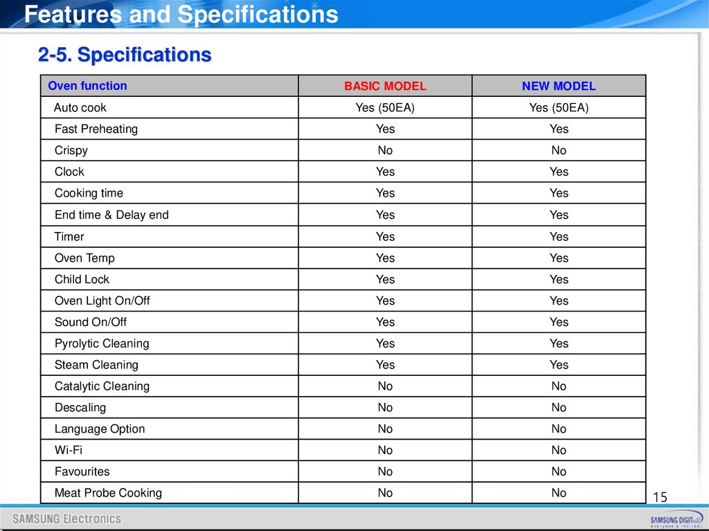
Oven function
BASIC MODEL
NEW MODEL
Auto cook
Yes (50EA)
Yes (50EA)
Fast Preheating
Yes
Yes
Crispy
No
No
Clock
Yes
Yes
Cooking time
Yes
Yes
End time & Delay end
Yes
Yes
Timer
Yes
Yes
Oven Temp
Yes
Yes
Child Lock
Yes
Yes
Oven Light On/Off
Yes
Yes
Sound On/Off
Yes
Yes
Pyrolytic Cleaning
Yes
Yes
Steam Cleaning
Yes
Yes
Catalytic Cleaning
No
No
Descaling
No
No
Language Option
No
No
Wi-Fi
No
No
Favourites
No
No
Meat Probe Cooking
No
No
15
16.
Features and Specifications2-5. Specifications
Accessory
BASIC MODEL
NEW MODEL
Divider
1EA
1EA
Wire rack
1EA
1EA
Wire rack insert
-
1EA
Baking tray
-
-
Universal tray
2EA
1EA
Extra-deep tray
-
-
Rotisserie spit
-
-
Shashlik
-
-
Telescopic rails
Yes
Yes
Meat probe
-
-
Model information
BASIC MODEL
NEW MODEL
Power Source
230-240V~ 50Hz
230-240V~ 50Hz
Output Power
3650 – 3950W
3650 – 3950W
Oven Capacity
75L
75L
Energy Class
A
A
Oven Weight (Net / Gross)
41.3kg / 44.1kg
41.0kg / 43.7kg
Oven Outside Dimension
(W x H x D)
595 x 595 x 566
595 x 595 x 566
16
17.
Installation3-1. How to install the oven
IMPORTANT
Any electrical installation work must be carried out by a qualified electrician / competent person.
The oven must be installed according to the instructions supplied.
Safety Instructions for the Installer
Protection against access to live parts must be guaranteed by the installation.
The unit in which the appliance is fitted must satisfy the requirements of DIN 68930 in respect
of stability. This oven must be installed by qualified personnel to the relevant Standards.
This oven is heavy. Take care when moving it. Remove all packaging, both inside and outside
the oven before using the oven. Do not attempt to modify the oven in any way.
17
18.
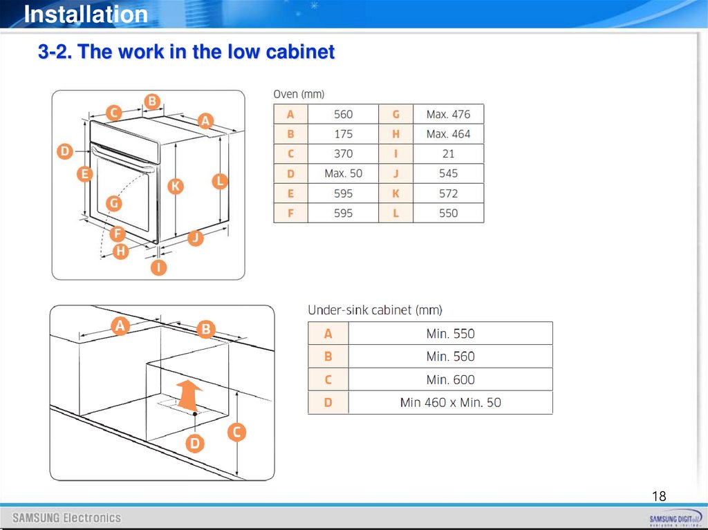
Installation3-2. The work in the low cabinet
18
19.
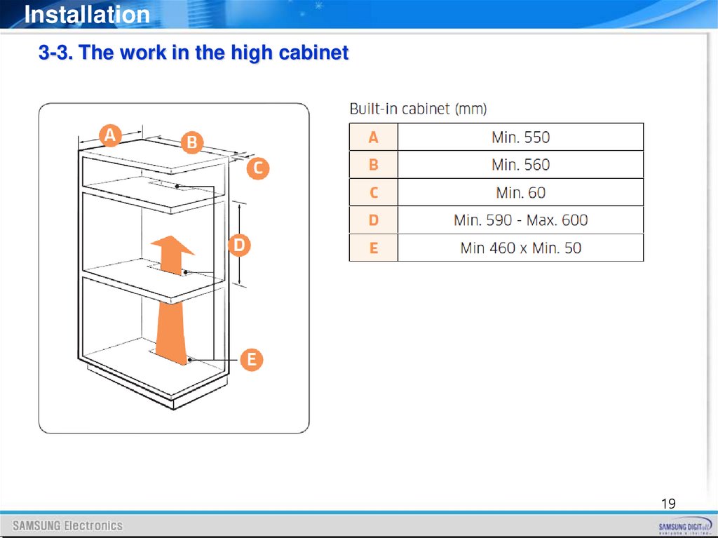
Installation3-3. The work in the high cabinet
19
20.
Installation3-4. Caution during installation
Do not open the oven door on the floor.
Secure at least 3 mm of gap in the picture so
that the door opens and closes smoothly.
20
21.
Installation3-5. Power connection
- Connecting the oven to the power supply (H05VV-F, H05RR-F, Min 1.5m, 1.5~2.5 mm²)
- Connections
Electrical connections must be made as per the connection plate fixed
to the back of the appliance, by an electrical fitter who must ensure
that the appliance has been connected up in accordance with fitting
instructions and local regulations.
Where the appliance is not connected to the mains electricity supply
by a plug, an omni polar cutout device (with a contacts gap of at least 3 mm)
must be fitted on the supply side of the connection to meet safety requirements.
NOTE: When power is connected, the electronics of the oven are initialized;
this neutralizes the lighting for a few seconds. The electric cable (H05 RR-F or H05VV-F)
must be long enough for it to be connected to the built - in oven standing on the floor in
front of its unit.
Open the back cover of the oven at the bottom (using a flat - bladed screwdriver),
completely unscrew the connection screw and the cable clamp before fitting the conducting
wires into the appropriate terminals.
- The earth wire must be connected to the
terminal of the oven.
If the oven is connected to the power supply by a plug, this must remain accessible once the oven has
been fitted.
We cannot accept any liability in the event of an accident resulting from non - existent or faulty
earthgrounding.
21
22.
Function4-1. Cooking Mode
Cooking Mode
Use of cooking mode
Convection
The rear heating element generates heat, which is evenly distributed by the convection fan.
Use this mode for baking and roasting on different levels at the same time.
Conventional
The heat is generated from the top and bottom heating elements. This function should be
used for standard baking and roasting for most types of dishes.
Top heat + convection
The top heating element generates heat, which is evenly distributed by the convection fan.
Use this mode for roasting that requires a crispy top (for example, meat or lasagne).
Bottom heat + convection
The bottom heating element generates heat, which is evenly distributed by the convection
fan. Use this mode for pizza, bread, or cake.
Large grill
The large-area grill emits heat. Use this mode for browning the tops of food (for example,
meat, lasagne, or gratin).
Eco grill
The small-area grill emits heat. Use this mode for food that requires less heat, such as fish
and filled baguettes.
Bottom heat
The bottom heating element generates heat. Use this mode at the end of baking or cooking
to brown the bottoms of a quiche or pizza.
Pro-Roasting
Pro-Roasting runs an automatic pre-heating cycle until the oven temperature reaches
220 °C. Then, the top heating element and the convection fan start operating to sear food
such as meat. After searing, the meat will be cooked at low temperatures. Use this mode
for beef, poultry, or fish.
Eco convection
Eco Convection uses the optimized heating system to save energy while cooking. The
cooking times slightly increases, but the cooking results remain the same. Note that this
mode does not require preheating.
22
23.
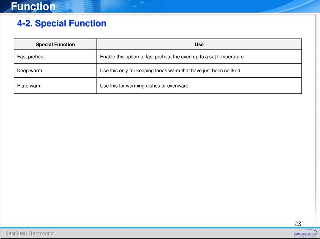
Function4-2. Special Function
Special Function
Use
Fast preheat
Enable this option to fast preheat the oven up to a set temperature.
Keep warm
Use this only for keeping foods warm that have just been cooked.
Plate warm
Use this for warming dishes or ovenware.
23
24.
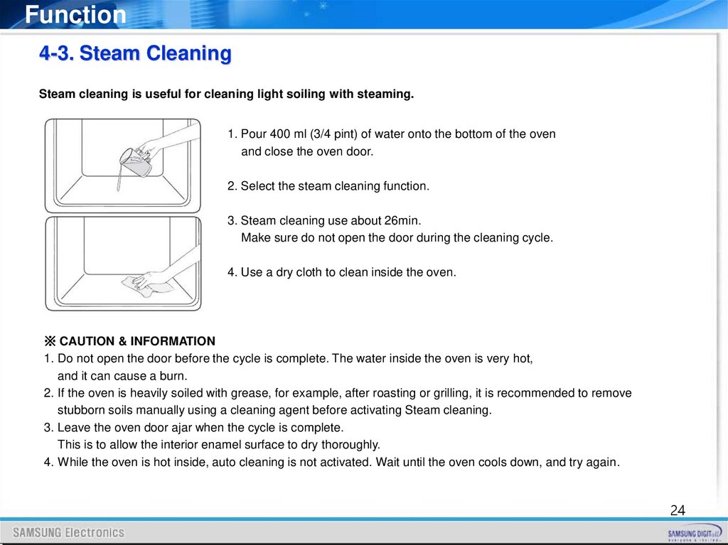
Function4-3. Steam Cleaning
Steam cleaning is useful for cleaning light soiling with steaming.
1. Pour 400 ml (3/4 pint) of water onto the bottom of the oven
and close the oven door.
2. Select the steam cleaning function.
3. Steam cleaning use about 26min.
Make sure do not open the door during the cleaning cycle.
4. Use a dry cloth to clean inside the oven.
※ CAUTION & INFORMATION
1. Do not open the door before the cycle is complete. The water inside the oven is very hot,
and it can cause a burn.
2. If the oven is heavily soiled with grease, for example, after roasting or grilling, it is recommended to remove
stubborn soils manually using a cleaning agent before activating Steam cleaning.
3. Leave the oven door ajar when the cycle is complete.
This is to allow the interior enamel surface to dry thoroughly.
4. While the oven is hot inside, auto cleaning is not activated. Wait until the oven cools down, and try again.
24
25.
Service Information5-1. Information Codes
Change the current time to 0:00 and press [Timer] and [Back] key for 5 seconds at the same time.
You can check the recent 5 information codes in the display.
But, if the oven turns off, the stored information codes are deleted. [Timer] and [Back] key for 5
seconds at the same time to return to ‘normal display mode’.
25
26.
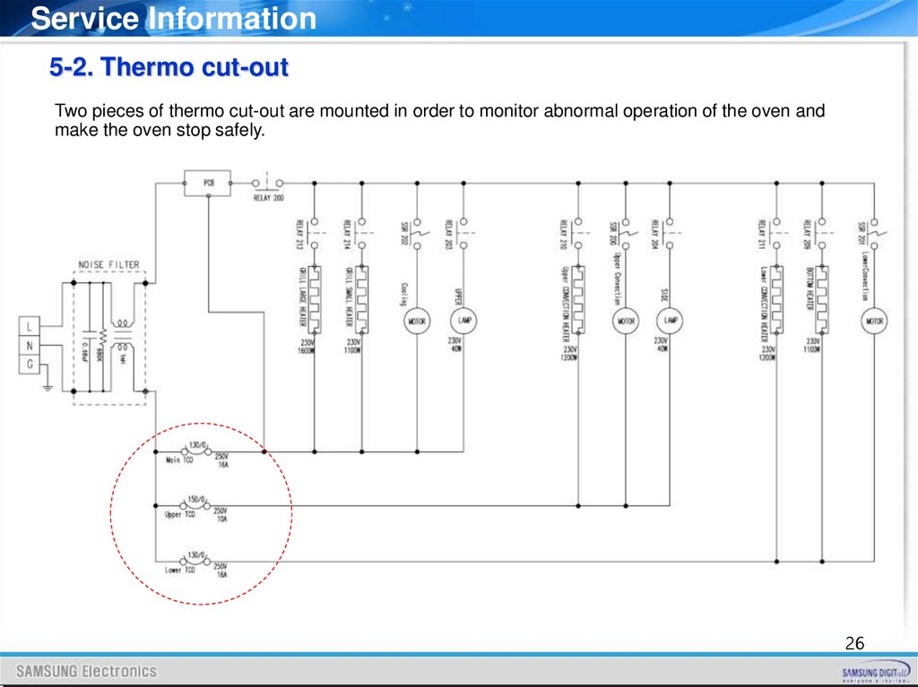
Service Information5-2. Thermo cut-out
Two pieces of thermo cut-out are mounted in order to monitor abnormal operation of the oven and
make the oven stop safely.
26
27.
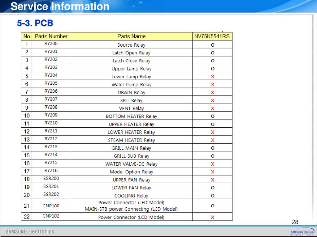
Service Information5-3. PCB
The operating power of Main PCB performs stable operation at a large range of Input Power from
100V to 270V with applied to SMPS circuits.
Also, it automatically makes power off in SMPS against abnormal operation and parts short of PCB
inside. When problem occur inside SMPS, the fuse is shorted and protects circuits.
27
28.
Service Information5-3. PCB
28
29.
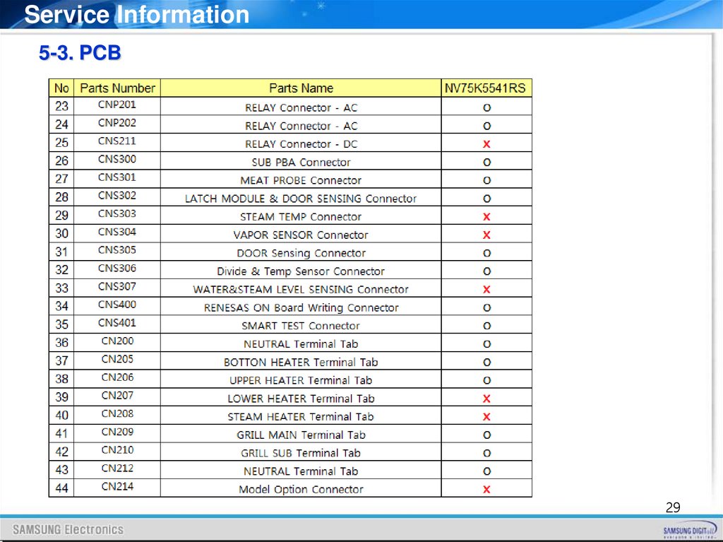
Service Information5-3. PCB
29
30.
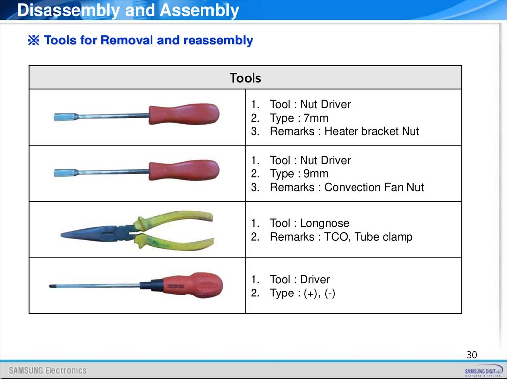
Disassembly and Assembly※ Tools for Removal and reassembly
Tools
1. Tool : Nut Driver
2. Type : 7mm
3. Remarks : Heater bracket Nut
1. Tool : Nut Driver
2. Type : 9mm
3. Remarks : Convection Fan Nut
1. Tool : Longnose
2. Remarks : TCO, Tube clamp
1. Tool : Driver
2. Type : (+), (-)
30
31.
Disassembly and Assembly6 - 1 Replacement of Door Assembly
※ Do not remove the door glass unless for cleaning purposes.
1. Open the door and flip open the clips at both hinges.
2. Close the door approximately 70°.
Hold the oven door by the sides using both hands, and lift and pull
upwards until the hinges are removed.
3. Clean the door with soapy water and a clean cloth.
4. When done, follow steps 1 to 2 above in the reverse order to
reinstall the door. Make sure the clips are hinged on both sides.
31
32.
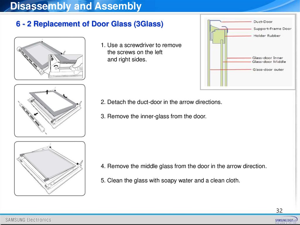
Disassembly and Assembly6 - 2 Replacement of Door Glass (3Glass)
1. Use a screwdriver to remove
the screws on the left
and right sides.
2. Detach the duct-door in the arrow directions.
3. Remove the inner-glass from the door.
4. Remove the middle glass from the door in the arrow direction.
5. Clean the glass with soapy water and a clean cloth.
32
33.
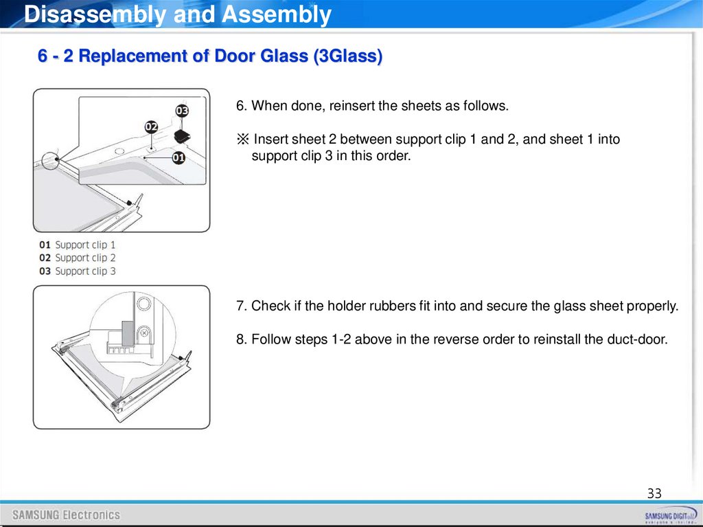
Disassembly and Assembly6 - 2 Replacement of Door Glass (3Glass)
6. When done, reinsert the sheets as follows.
※ Insert sheet 2 between support clip 1 and 2, and sheet 1 into
support clip 3 in this order.
7. Check if the holder rubbers fit into and secure the glass sheet properly.
8. Follow steps 1-2 above in the reverse order to reinstall the duct-door.
33
34.
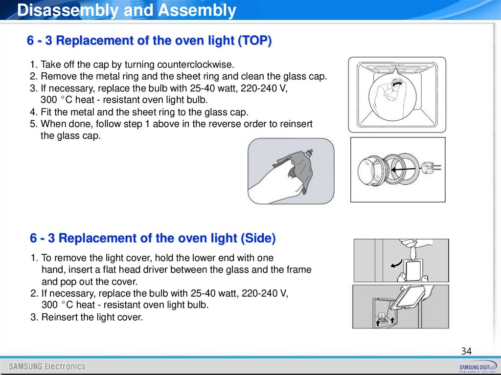
Disassembly and Assembly6 - 3 Replacement of the oven light (TOP)
1. Take off the cap by turning counterclockwise.
2. Remove the metal ring and the sheet ring and clean the glass cap.
3. If necessary, replace the bulb with 25-40 watt, 220-240 V,
300 °C heat - resistant oven light bulb.
4. Fit the metal and the sheet ring to the glass cap.
5. When done, follow step 1 above in the reverse order to reinsert
the glass cap.
6 - 3 Replacement of the oven light (Side)
1. To remove the light cover, hold the lower end with one
hand, insert a flat head driver between the glass and the frame
and pop out the cover.
2. If necessary, replace the bulb with 25-40 watt, 220-240 V,
300 °C heat - resistant oven light bulb.
3. Reinsert the light cover.
34
35.
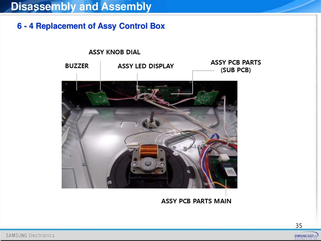
Disassembly and Assembly6 - 4 Replacement of Assy Control Box
ASSY KNOB DIAL
BUZZER
ASSY LED DISPLAY
ASSY PCB PARTS
(SUB PCB)
ASSY PCB PARTS MAIN
35
36.
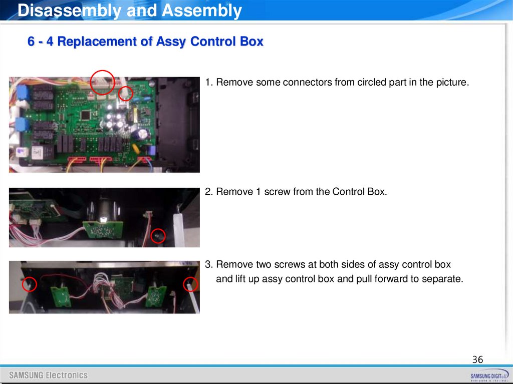
Disassembly and Assembly6 - 4 Replacement of Assy Control Box
1. Remove some connectors from circled part in the picture.
2. Remove 1 screw from the Control Box.
3. Remove two screws at both sides of assy control box
and lift up assy control box and pull forward to separate.
36
37.
Disassembly and Assembly6 - 4 Replacement of Assy Control Box
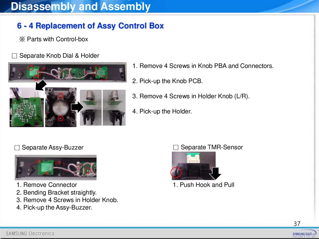
※ Parts with Control-box
□ Separate Knob Dial & Holder
1. Remove 4 Screws in Knob PBA and Connectors.
2. Pick-up the Knob PCB.
3. Remove 4 Screws in Holder Knob (L/R).
4. Pick-up the Holder.
□ Separate Assy-Buzzer
□ Separate TMR-Sensor
1. Remove Connector
2. Bending Bracket straightly.
3. Remove 4 Screws in Holder Knob.
4. Pick-up the Assy-Buzzer.
1. Push Hook and Pull
37
38.
Disassembly and Assembly6 - 4 Replacement of Assy Control Box
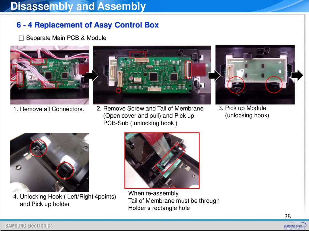
□ Separate Main PCB & Module
1. Remove all Connectors.
2. Remove Screw and Tail of Membrane
(Open cover and pull) and Pick up
PCB-Sub ( unlocking hook )
4. Unlocking Hook ( Left/Right 4points)
and Pick up holder
3. Pick up Module
(unlocking hook)
When re-assembly,
Tail of Membrane must be through
Holder’s rectangle hole
38
39.
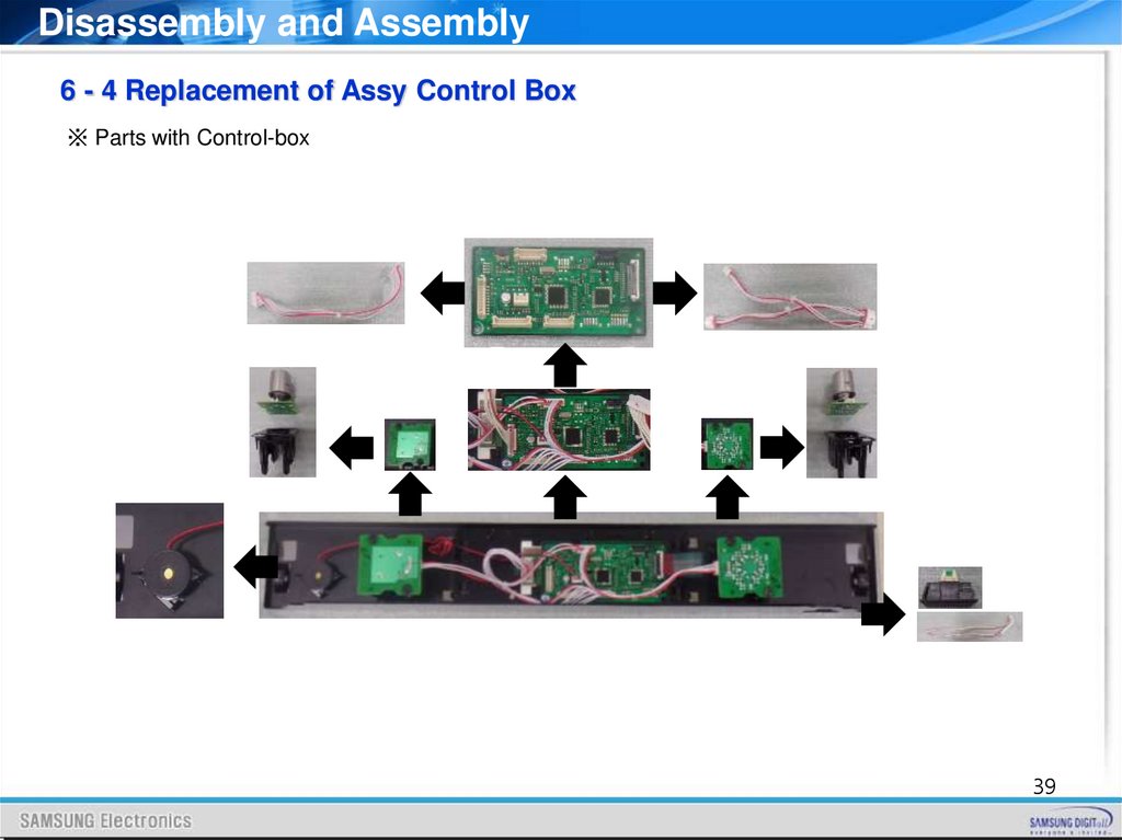
Disassembly and Assembly6 - 4 Replacement of Assy Control Box
※ Parts with Control-box
39
40.
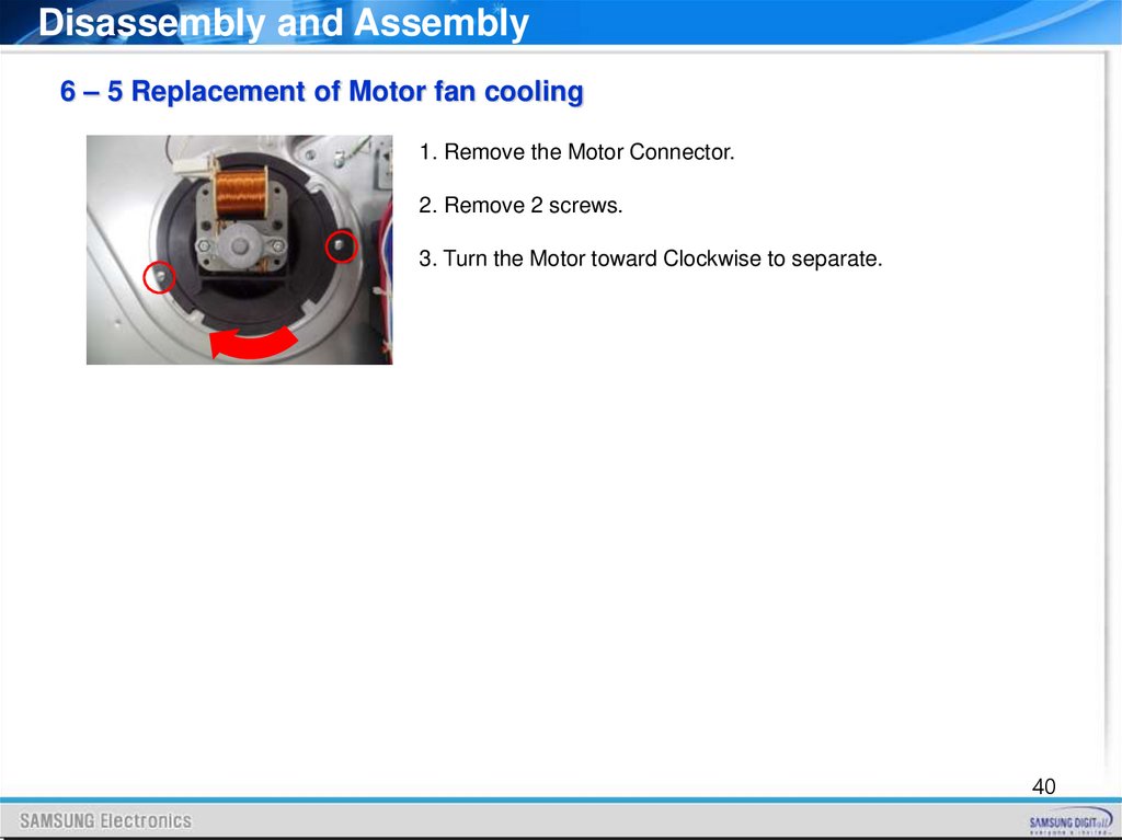
Disassembly and Assembly6 – 5 Replacement of Motor fan cooling
1. Remove the Motor Connector.
2. Remove 2 screws.
3. Turn the Motor toward Clockwise to separate.
40
41.
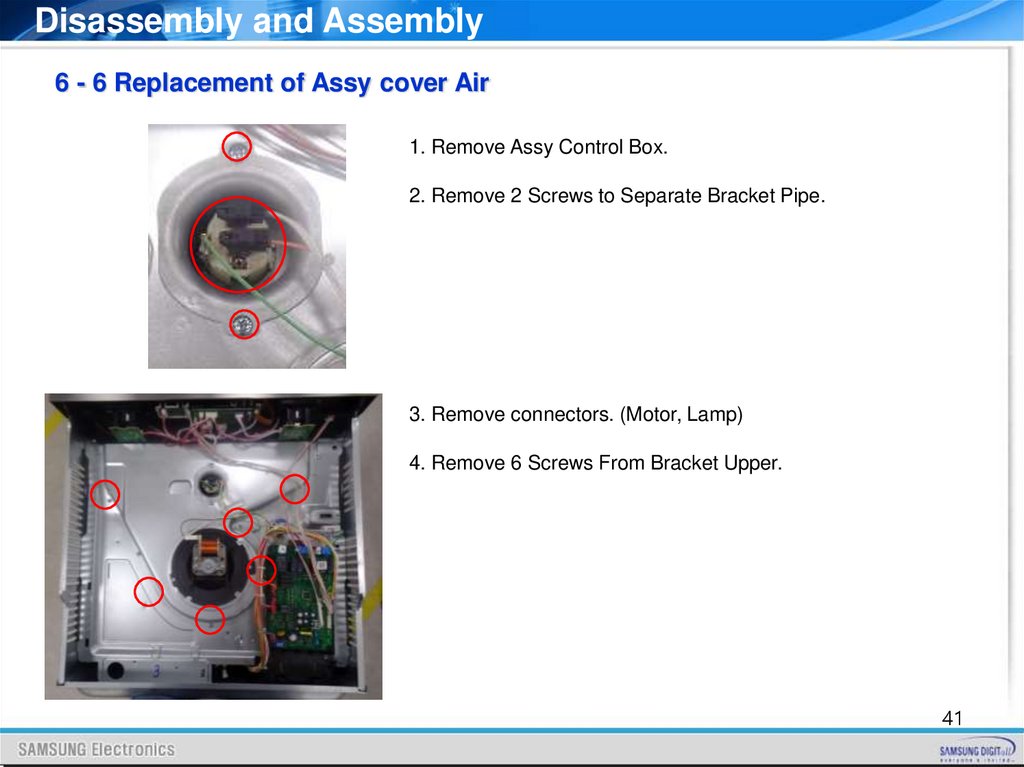
Disassembly and Assembly6 - 6 Replacement of Assy cover Air
1. Remove Assy Control Box.
2. Remove 2 Screws to Separate Bracket Pipe.
3. Remove connectors. (Motor, Lamp)
4. Remove 6 Screws From Bracket Upper.
41
42.
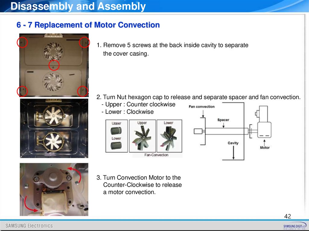
Disassembly and Assembly6 - 7 Replacement of Motor Convection
1. Remove 5 screws at the back inside cavity to separate
the cover casing.
2. Turn Nut hexagon cap to release and separate spacer and fan convection.
- Upper : Counter clockwise
- Lower : Clockwise
3. Turn Convection Motor to the
Counter-Clockwise to release
a motor convection.
42
43.
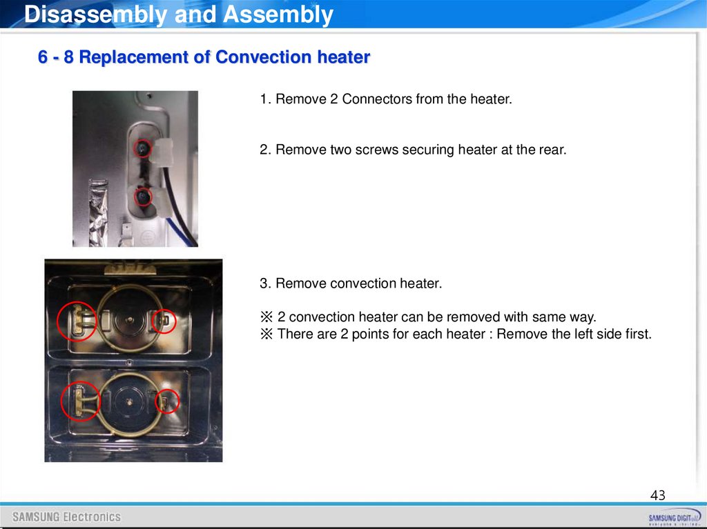
Disassembly and Assembly6 - 8 Replacement of Convection heater
1. Remove 2 Connectors from the heater.
2. Remove two screws securing heater at the rear.
3. Remove convection heater.
※ 2 convection heater can be removed with same way.
※ There are 2 points for each heater : Remove the left side first.
43
44.
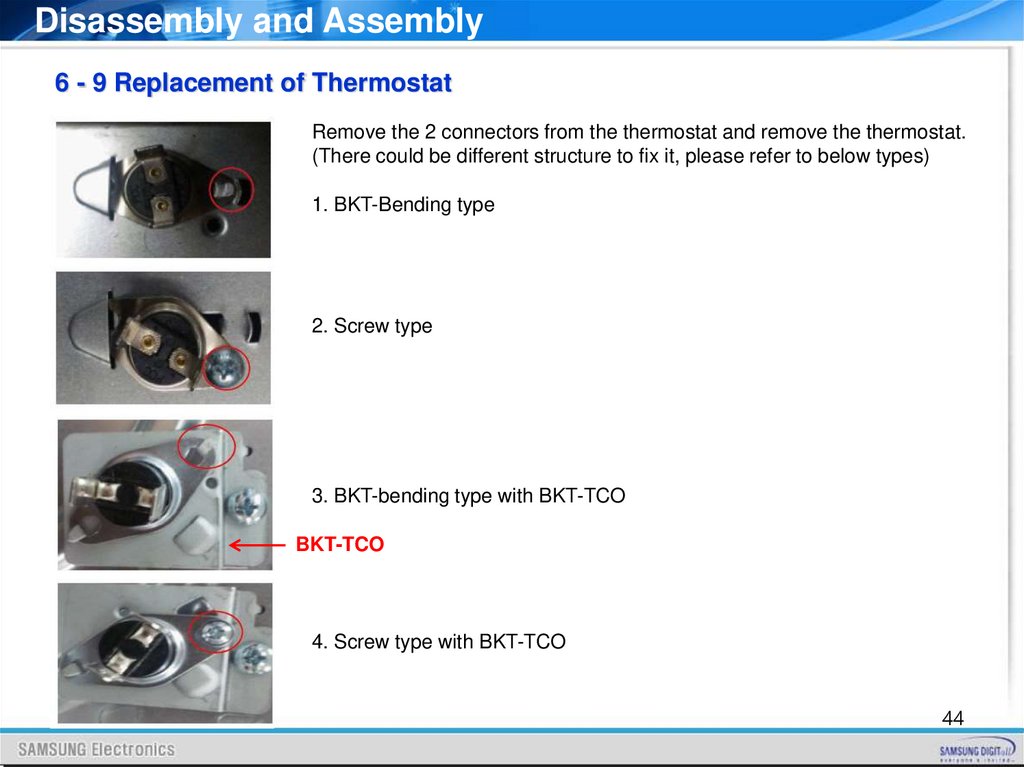
Disassembly and Assembly6 - 9 Replacement of Thermostat
Remove the 2 connectors from the thermostat and remove the thermostat.
(There could be different structure to fix it, please refer to below types)
1. BKT-Bending type
2. Screw type
3. BKT-bending type with BKT-TCO
BKT-TCO
4. Screw type with BKT-TCO
44
45.
Disassembly and Assembly6 - 10 Replacement of Sensor thermistor
1. Remove the connector from the sensor thermistor.
2. Remove the 1 screw.
6 - 11 Replacement of Terminal block
1. Remove the connectors from the terminal block.
2. Remove the 3 screws on it.
45
46.
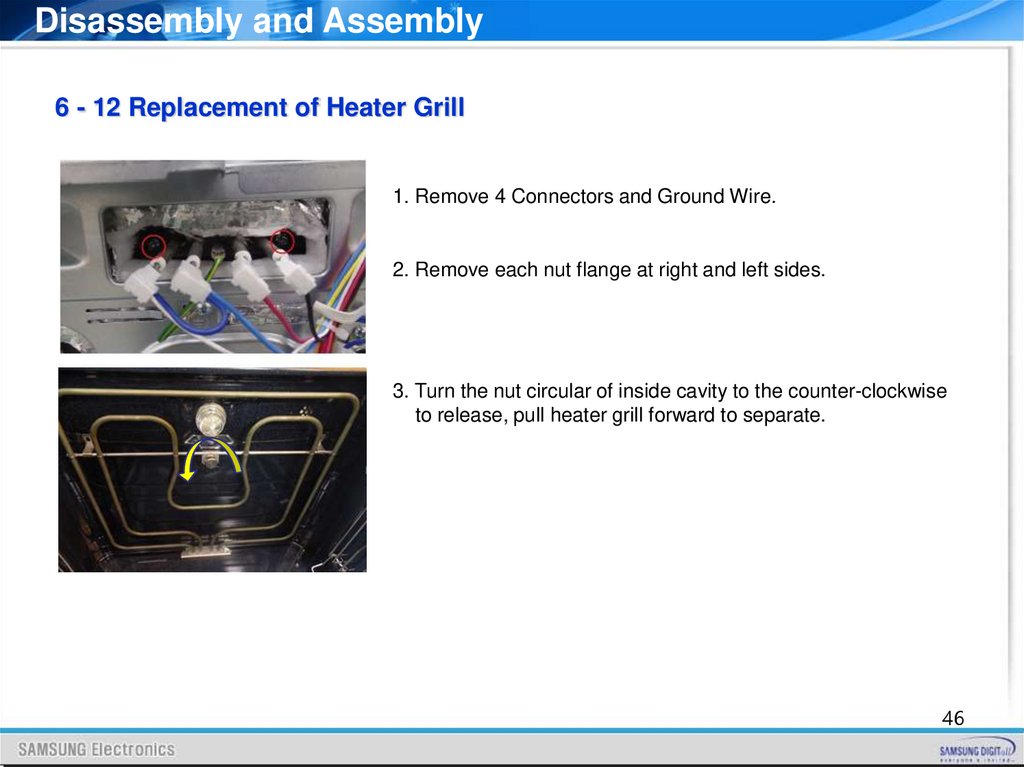
Disassembly and Assembly6 - 12 Replacement of Heater Grill
1. Remove 4 Connectors and Ground Wire.
2. Remove each nut flange at right and left sides.
3. Turn the nut circular of inside cavity to the counter-clockwise
to release, pull heater grill forward to separate.
46
47.
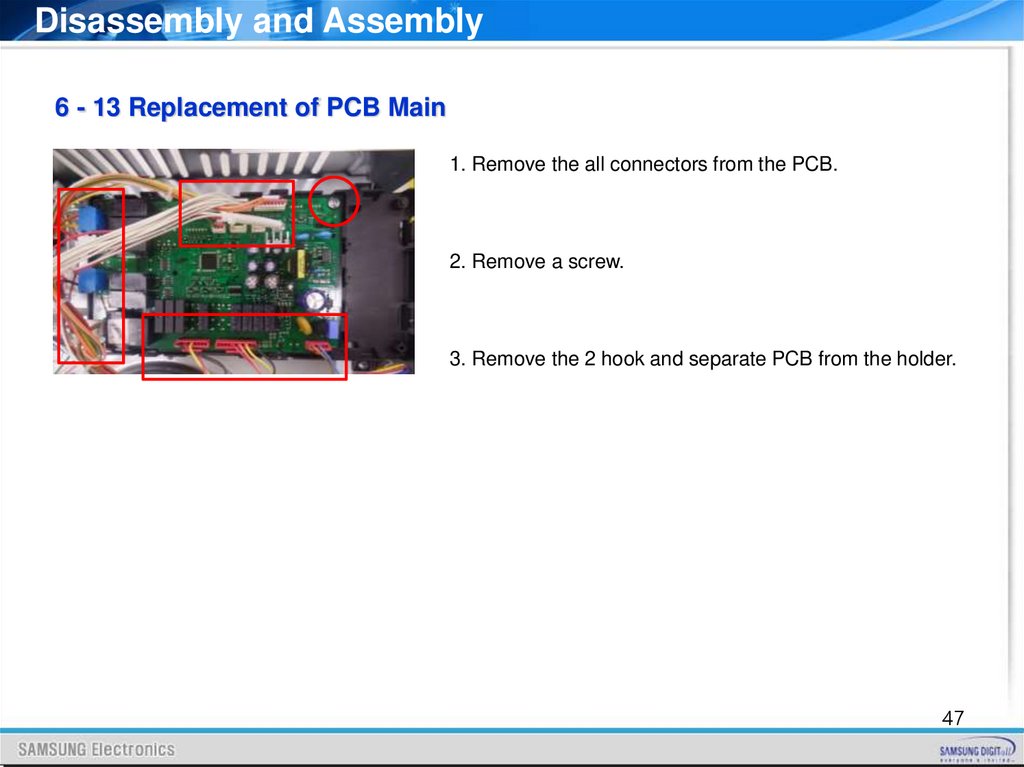
Disassembly and Assembly6 - 13 Replacement of PCB Main
1. Remove the all connectors from the PCB.
2. Remove a screw.
3. Remove the 2 hook and separate PCB from the holder.
47
48.
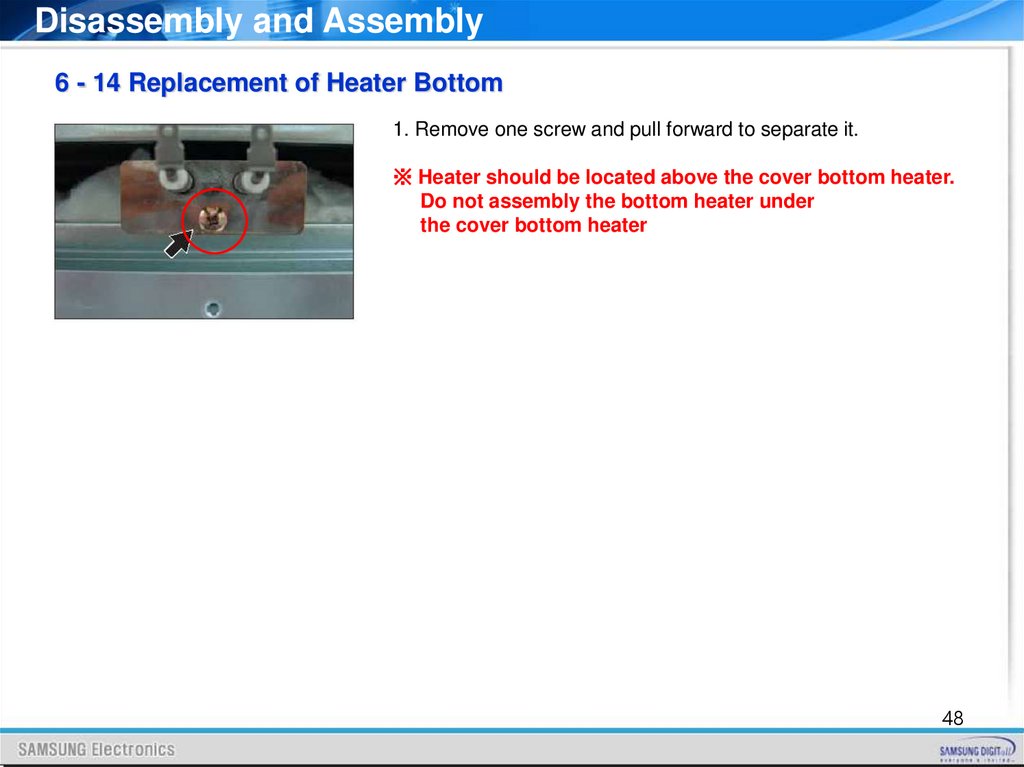
Disassembly and Assembly6 - 14 Replacement of Heater Bottom
1. Remove one screw and pull forward to separate it.
※ Heater should be located above the cover bottom heater.
Do not assembly the bottom heater under
the cover bottom heater
48
49.
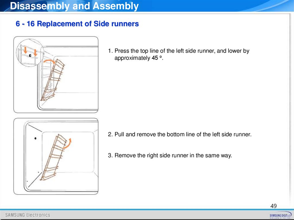
Disassembly and Assembly6 - 16 Replacement of Side runners
1. Press the top line of the left side runner, and lower by
approximately 45 º.
2. Pull and remove the bottom line of the left side runner.
3. Remove the right side runner in the same way.
49
50.
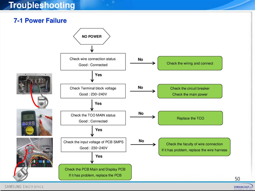
Troubleshooting7-1 Power Failure
NO POWER
Check wire connection status
No
Check the wiring and connect
Good : Connected
Yes
Check Terminal block voltage
No
Good : 230~240V
Check the circuit breaker
Check the main power
Yes
Check the TCO MAIN status
No
Replace the TCO
Good : Connected
Yes
Check the input voltage of PCB SMPS
Good : 230~240V
No
Check the faculty of wire connection
If it has problem, replace the wire harness
Yes
Check the PCB Main and Display PCB
If it has problem, replace the PCB
50
51.
Troubleshooting7-2 TCO Open
TCO OPEN
Check the TCO status
Good : Connected
Replace the TCO
※ Ex) TCO MAIN
※ Remove the 2 connectors from the TCO and remove the TCO.
(There could be different structure to fix it, please keep the original structure)
※ TCO & Related parts
No
TCO
Related Parts
1
TCO MAIN
PCB Main, Cooling Motor, Top Lamp, Grill Heater Inner/Outer
2
TCO UPPER
Upper Convection Heater, Upper Convection Motor, Side Lamp, (Optional) Spit Motor
3
TCO LOWER
Lower Convection Heater, Lower Convection Motor, Bottom Heater
51
52.
Troubleshooting7-3 PCB Failure
PCB FAILURE
Check the SMPS Input voltage
No
Good : 230~240V
Check the parts related power
(Circuit breaker, TCO, Wiring etc)
Yes
Check the SMPS Output DC voltage
No
Good : 5V (DC)
SMPS Problem : Replace the PCB Main
5V
Yes
CNS300
Check the Main & Sub PCB DC signal(CNS300)
No
Good : 12V(PIN1), 5V(PIN3)
PCB Main Problem : Replace the PCB Main
Yes
CN103
Check the DC signal on PCB Sub(CN103)
Good : 12V(PIN1), 5V(PIN3)
No
Replace the communication Wire-harness
Yes
PCB Sub Problem : Replace the PCB Sub
52
53.
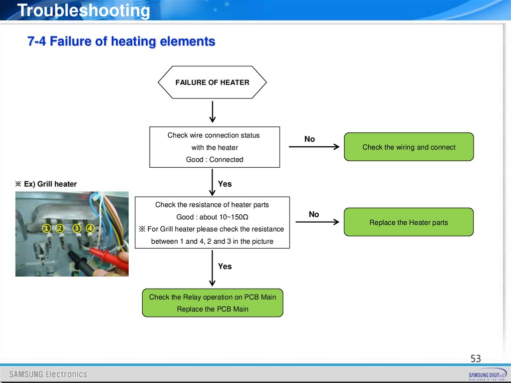
Troubleshooting7-4 Failure of heating elements
FAILURE OF HEATER
Check wire connection status
No
Check the wiring and connect
with the heater
Good : Connected
※ Ex) Grill heater
Yes
Check the resistance of heater parts
①② ③④
Good : about 10~150Ω
※ For Grill heater please check the resistance
No
Replace the Heater parts
between 1 and 4, 2 and 3 in the picture
Yes
Check the Relay operation on PCB Main
Replace the PCB Main
53
54.
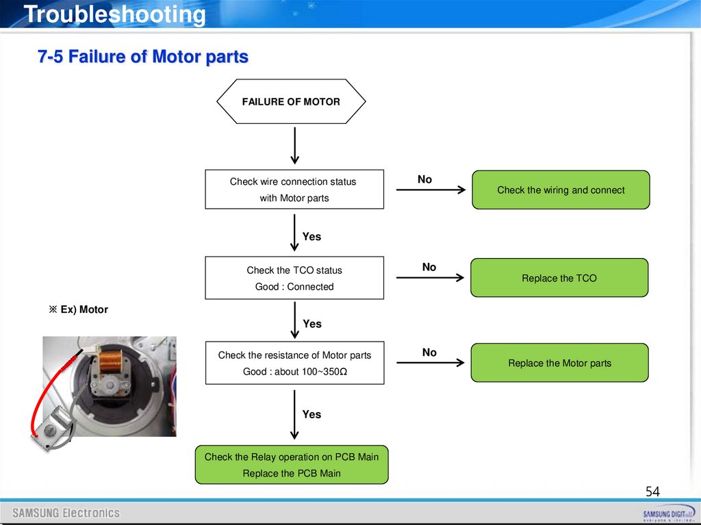
Troubleshooting7-5 Failure of Motor parts
FAILURE OF MOTOR
Check wire connection status
No
Check the wiring and connect
with Motor parts
Yes
Check the TCO status
No
Replace the TCO
Good : Connected
※ Ex) Motor
Yes
Check the resistance of Motor parts
Good : about 100~350Ω
No
Replace the Motor parts
Yes
Check the Relay operation on PCB Main
Replace the PCB Main
54
55.
Troubleshooting7-5 Information Code
55
56.
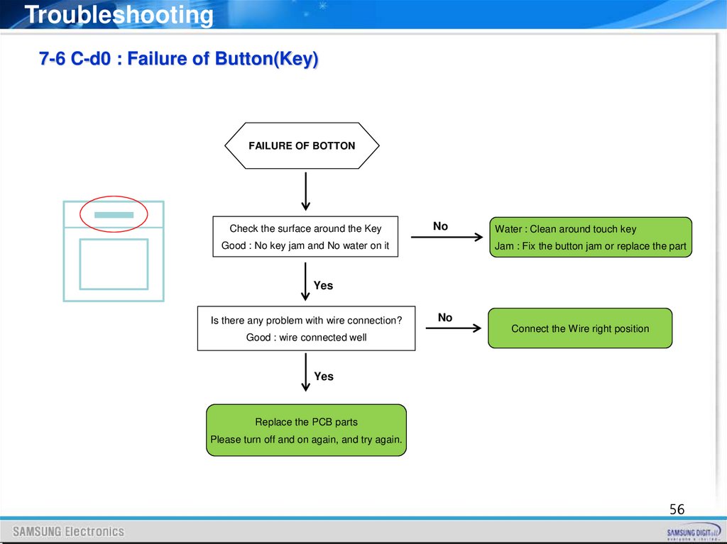
Troubleshooting7-6 C-d0 : Failure of Button(Key)
FAILURE OF BOTTON
Check the surface around the Key
No
Good : No key jam and No water on it
Water : Clean around touch key
Jam : Fix the button jam or replace the part
Yes
Is there any problem with wire connection?
Good : wire connected well
No
Connect the Wire right position
Yes
Replace the PCB parts
Please turn off and on again, and try again.
56
57.
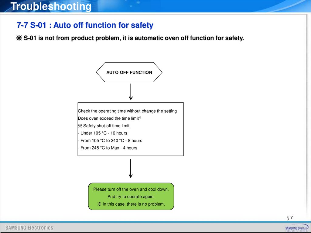
Troubleshooting7-7 S-01 : Auto off function for safety
※ S-01 is not from product problem, it is automatic oven off function for safety.
AUTO OFF FUNCTION
Check the operating time without change the setting
Does oven exceed the time limit?
※ Safety shut-off time limit
- Under 105 °C - 16 hours
- From 105 °C to 240 °C - 8 hours
- From 245 °C to Max - 4 hours
Please turn off the oven and cool down.
And try to operate again.
※ In this case, there is no problem.
57
58.
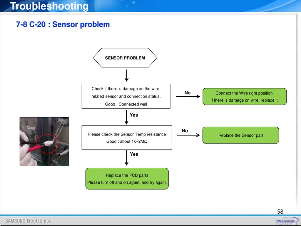
Troubleshooting7-8 C-20 : Sensor problem
SENSOR PROBLEM
Check if there is damage on the wire
related sensor and connection status.
No
Connect the Wire right position.
If there is damage on wire, replace it.
Good : Connected well
Yes
Please check the Sensor Temp resistance
No
Replace the Sensor part
Good : about 1k~2MΩ
Yes
Replace the PCB parts
Please turn off and on again, and try again.
58
59.
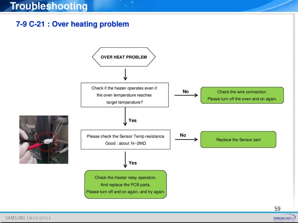
Troubleshooting7-9 C-21 : Over heating problem
OVER HEAT PROBLEM
Check if the heater operates even if
the oven temperature reaches
No
Check the wire connection.
Please turn off the oven and on again.
target temperature?
Yes
Please check the Sensor Temp resistance
Good : about 1k~2MΩ
No
Replace the Sensor part
Yes
Check the Heater relay operation.
And replace the PCB parts.
Please turn off and on again, and try again.
59
60.
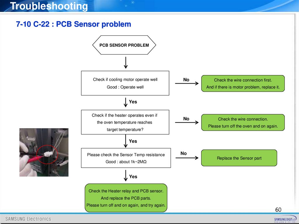
Troubleshooting7-10 C-22 : PCB Sensor problem
PCB SENSOR PROBLEM
Check if cooling motor operate well
No
Check the wire connection first.
And if there is motor problem, replace it.
Good : Operate well
Yes
Check if the heater operates even if
the oven temperature reaches
No
Check the wire connection.
Please turn off the oven and on again.
target temperature?
Yes
Please check the Sensor Temp resistance
Good : about 1k~2MΩ
No
Replace the Sensor part
Yes
Check the Heater relay and PCB sensor.
And replace the PCB parts.
Please turn off and on again, and try again.
60
61.
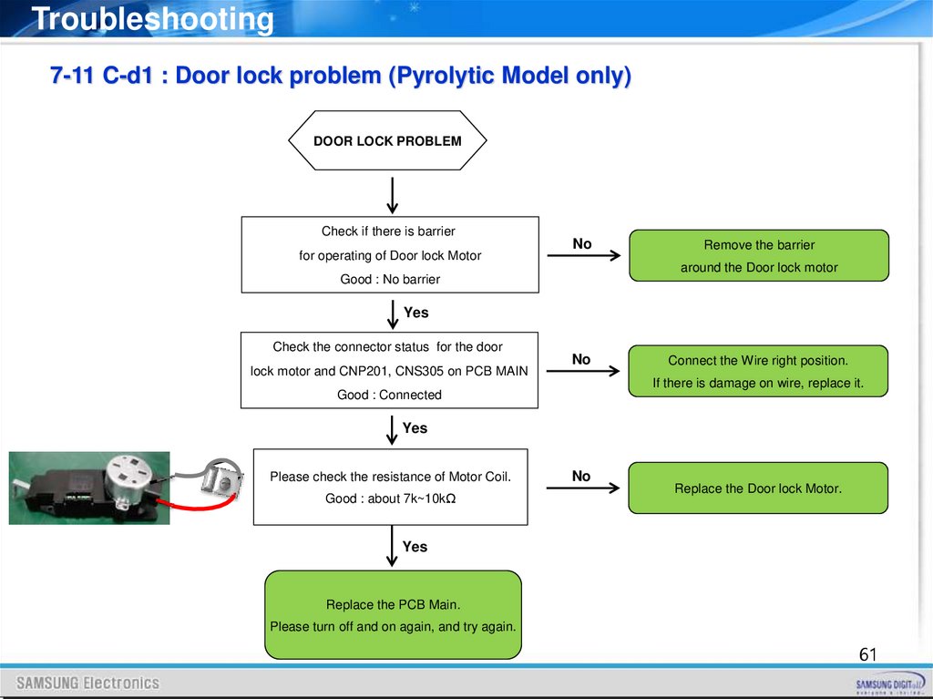
Troubleshooting7-11 C-d1 : Door lock problem (Pyrolytic Model only)
DOOR LOCK PROBLEM
Check if there is barrier
for operating of Door lock Motor
No
Remove the barrier
around the Door lock motor
Good : No barrier
Yes
Check the connector status for the door
lock motor and CNP201, CNS305 on PCB MAIN
No
Connect the Wire right position.
If there is damage on wire, replace it.
Good : Connected
Yes
Please check the resistance of Motor Coil.
Good : about 7k~10kΩ
No
Replace the Door lock Motor.
Yes
Replace the PCB Main.
Please turn off and on again, and try again.
61
62.
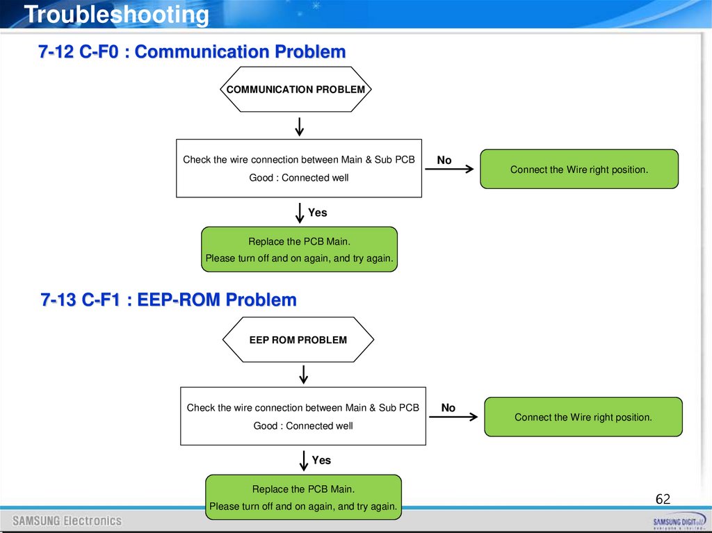
Troubleshooting7-12 C-F0 : Communication Problem
COMMUNICATION PROBLEM
Check the wire connection between Main & Sub PCB
No
Good : Connected well
Connect the Wire right position.
Yes
Replace the PCB Main.
Please turn off and on again, and try again.
7-13 C-F1 : EEP-ROM Problem
EEP ROM PROBLEM
Check the wire connection between Main & Sub PCB
Good : Connected well
No
Connect the Wire right position.
Yes
Replace the PCB Main.
Please turn off and on again, and try again.
62
63.
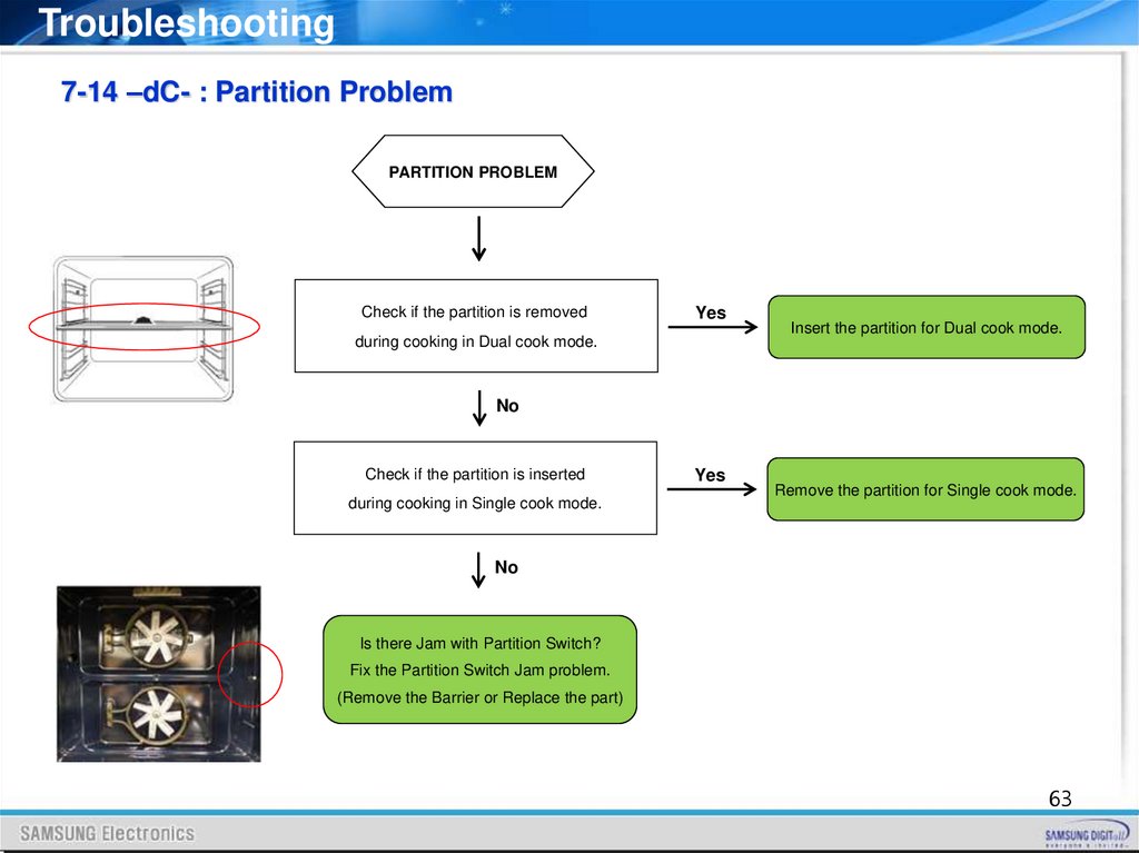
Troubleshooting7-14 –dC- : Partition Problem
PARTITION PROBLEM
Check if the partition is removed
Yes
during cooking in Dual cook mode.
Insert the partition for Dual cook mode.
No
Check if the partition is inserted
during cooking in Single cook mode.
Yes
Remove the partition for Single cook mode.
No
Is there Jam with Partition Switch?
Fix the Partition Switch Jam problem.
(Remove the Barrier or Replace the part)
63
64.
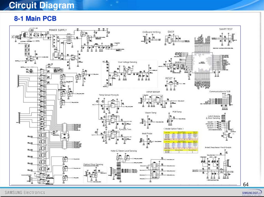
Circuit Diagram8-1 Main PCB
64
65.
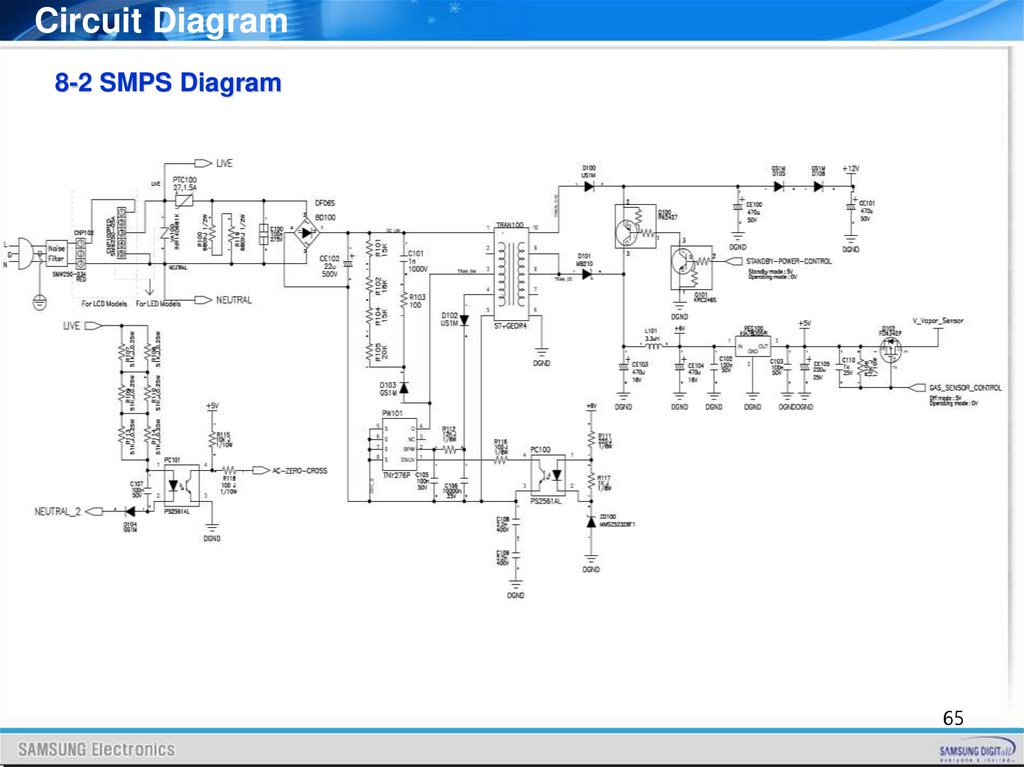
Circuit Diagram8-2 SMPS Diagram
65
66.
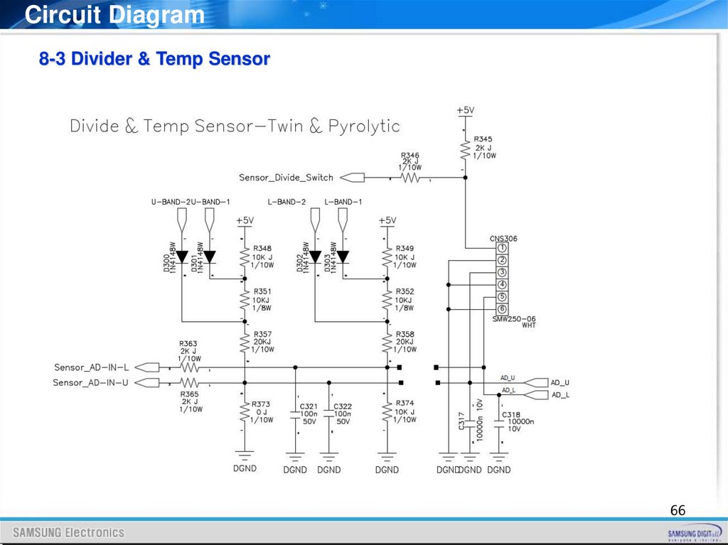
Circuit Diagram8-3 Divider & Temp Sensor
66
67.
Circuit Diagram8-4 Probe & Steam & PCB Temp
Vapour model only
Meat probe model only
67
68.
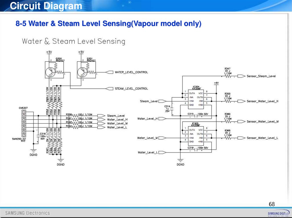
Circuit Diagram8-5 Water & Steam Level Sensing(Vapour model only)
68
69.
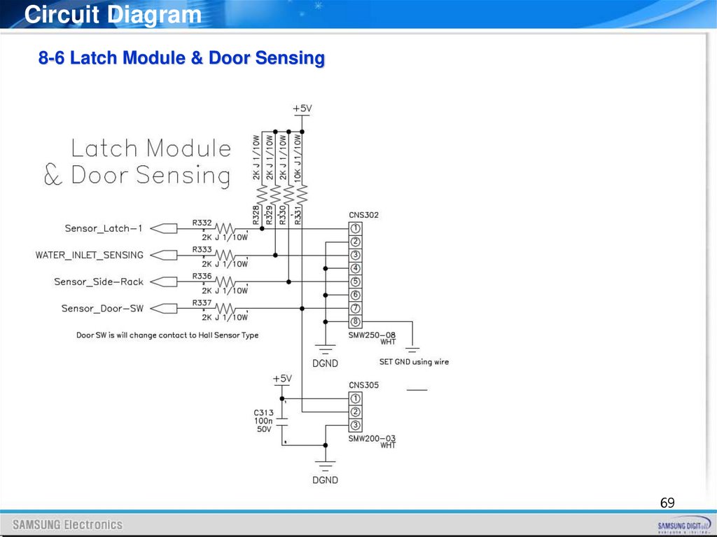
Circuit Diagram8-6 Latch Module & Door Sensing
69
70.
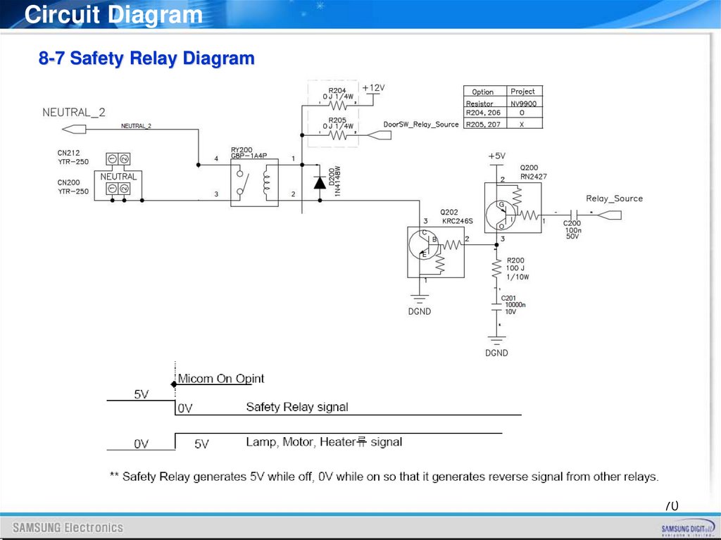
Circuit Diagram8-7 Safety Relay Diagram
70
71.
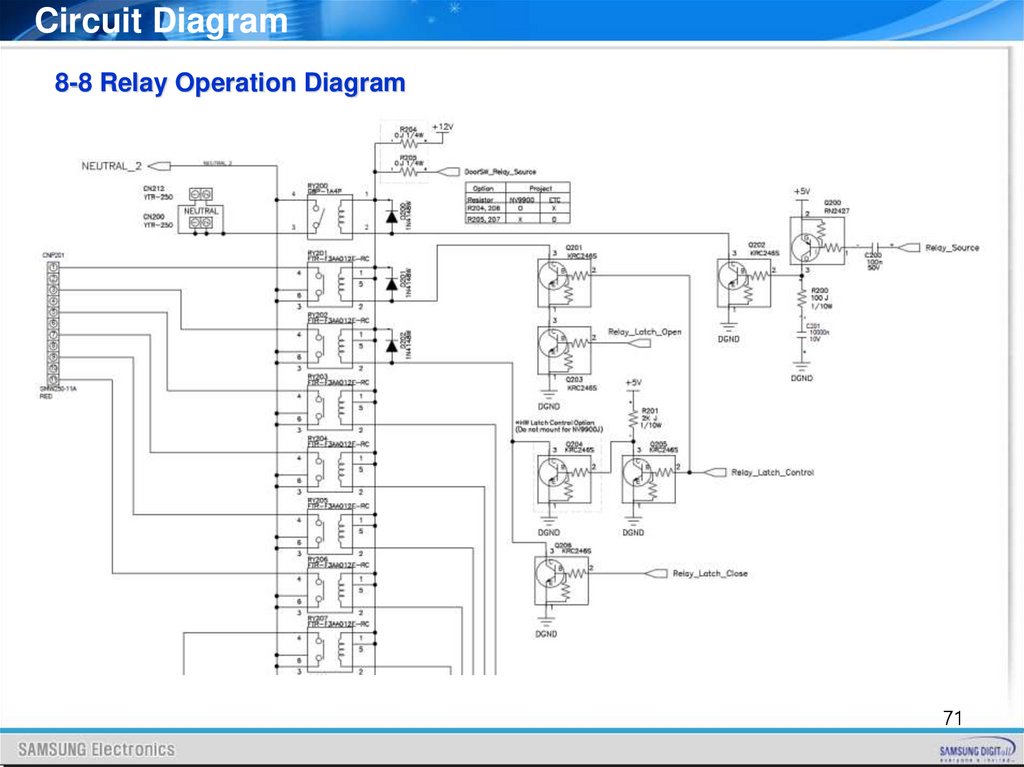
Circuit Diagram8-8 Relay Operation Diagram
71
72.
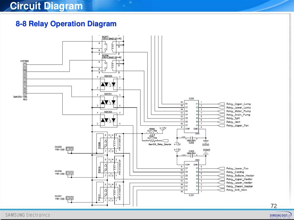
Circuit Diagram8-8 Relay Operation Diagram
72
73.
Circuit Diagram8-8 Relay Operation Diagram
73
74.
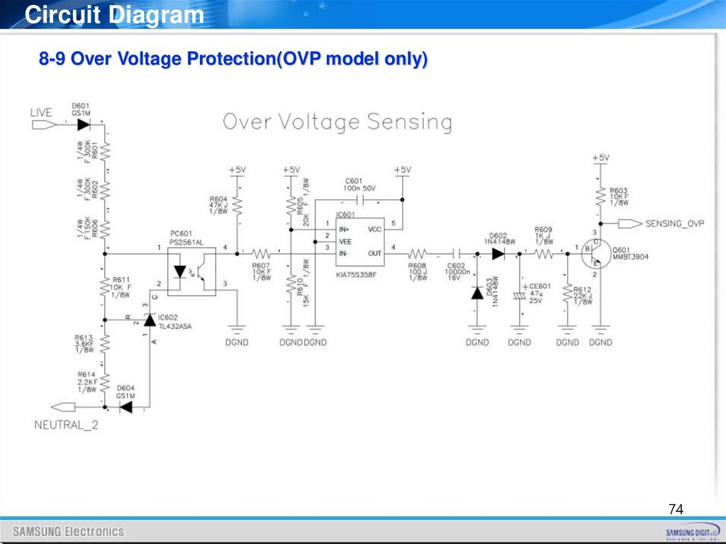
Circuit Diagram8-9 Over Voltage Protection(OVP model only)
74
75.
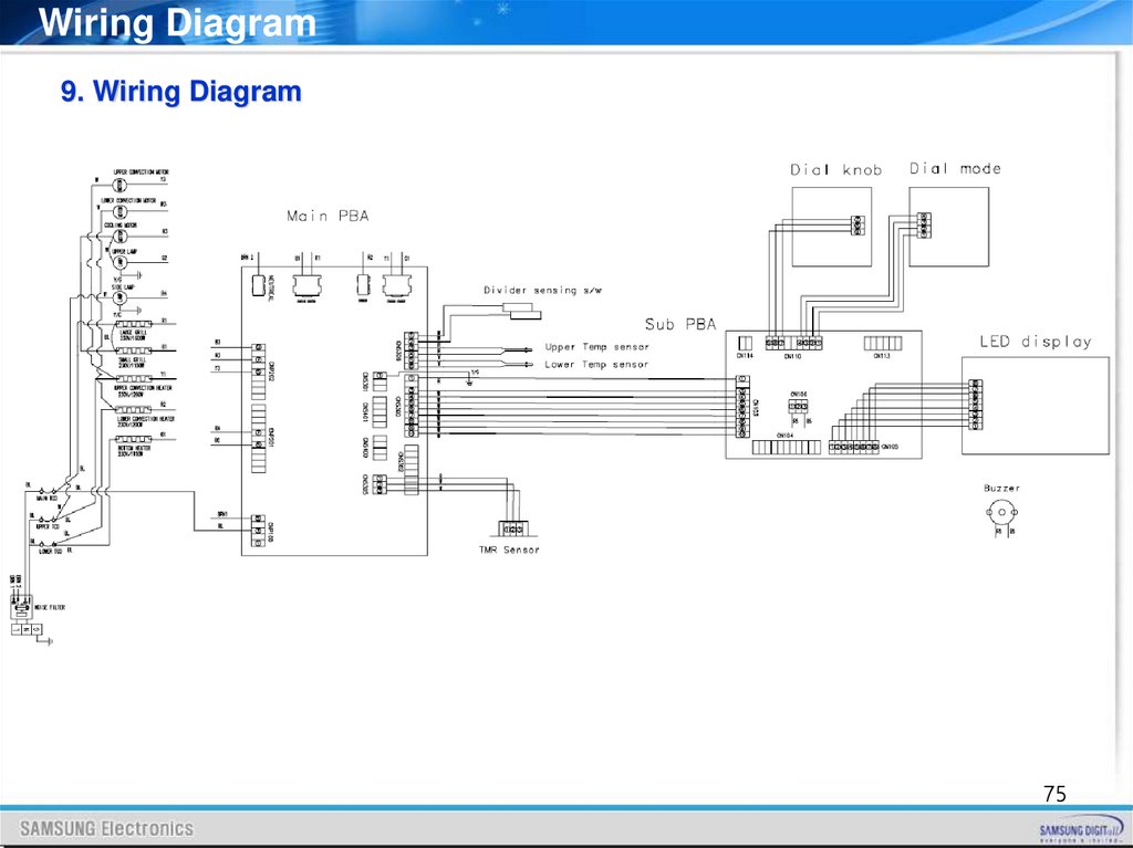
Wiring Diagram9. Wiring Diagram
75
76.
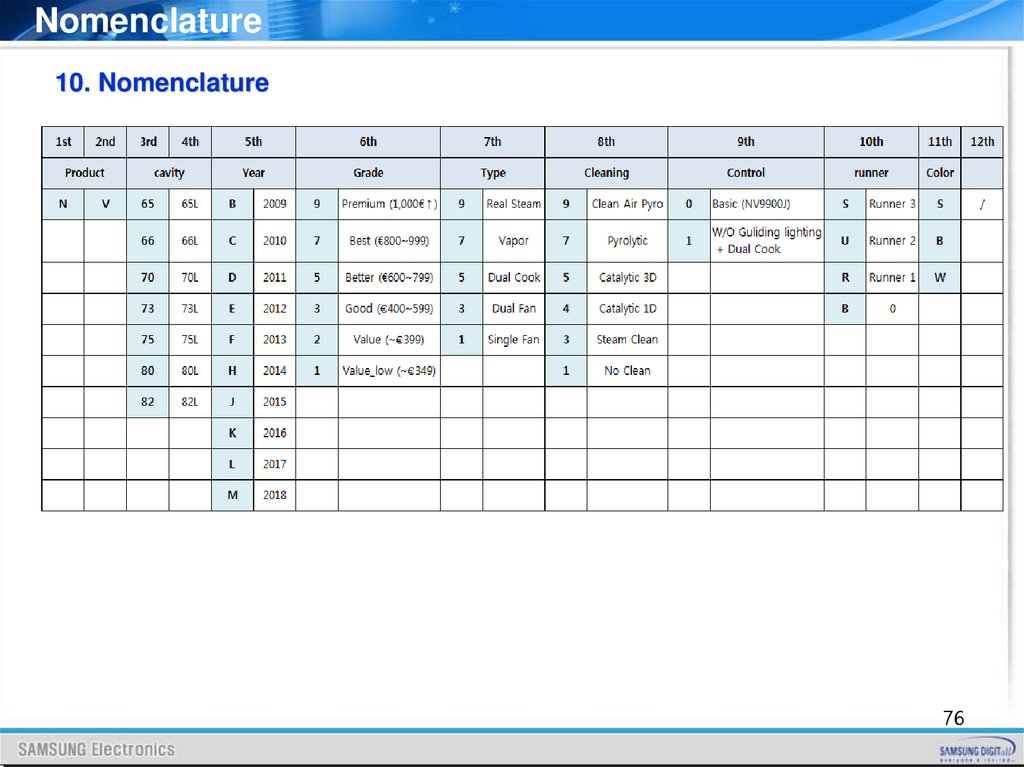
Nomenclature10. Nomenclature
76
77.
Q&A11. Q & A
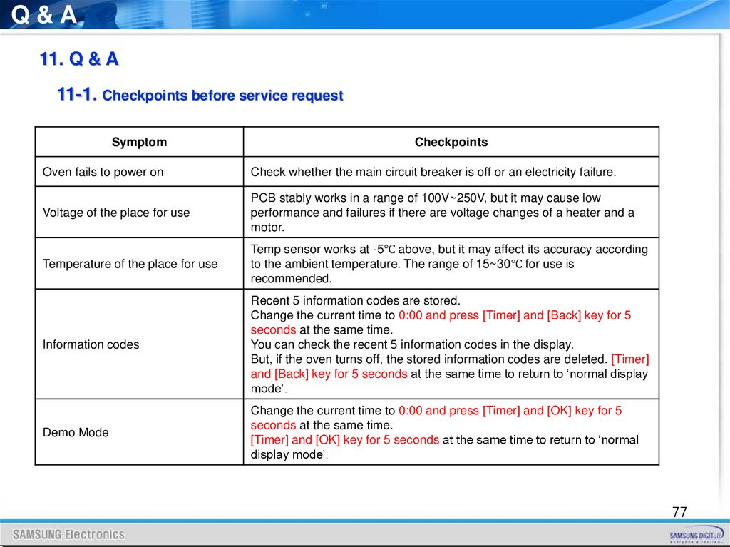
11-1. Checkpoints before service request
Symptom
Checkpoints
Oven fails to power on
Check whether the main circuit breaker is off or an electricity failure.
Voltage of the place for use
PCB stably works in a range of 100V~250V, but it may cause low
performance and failures if there are voltage changes of a heater and a
motor.
Temperature of the place for use
Temp sensor works at -5℃ above, but it may affect its accuracy according
to the ambient temperature. The range of 15~30℃ for use is
recommended.
Information codes
Recent 5 information codes are stored.
Change the current time to 0:00 and press [Timer] and [Back] key for 5
seconds at the same time.
You can check the recent 5 information codes in the display.
But, if the oven turns off, the stored information codes are deleted. [Timer]
and [Back] key for 5 seconds at the same time to return to ‘normal display
mode’.
Demo Mode
Change the current time to 0:00 and press [Timer] and [OK] key for 5
seconds at the same time.
[Timer] and [OK] key for 5 seconds at the same time to return to ‘normal
display mode’.
77
78.
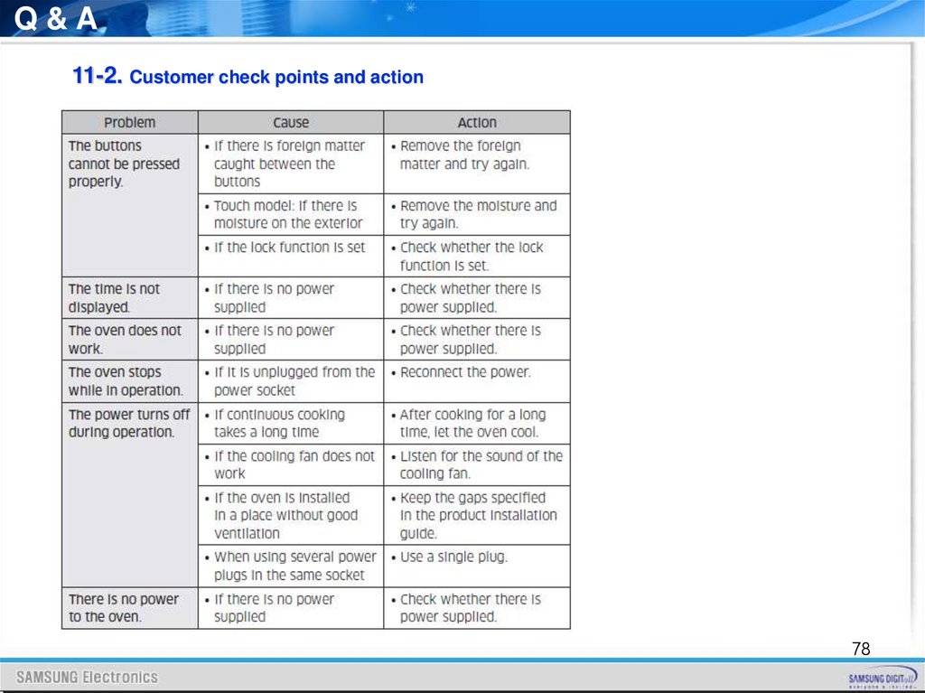
Q&A11-2. Customer check points and action
78
79.
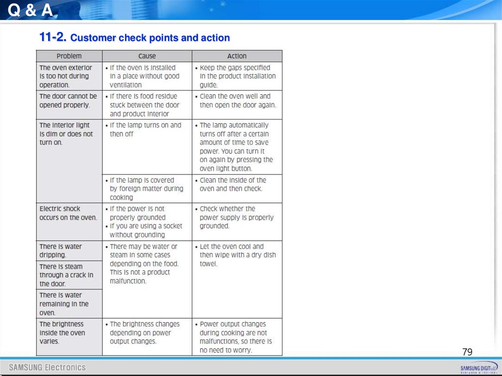
Q&A11-2. Customer check points and action
79
80.
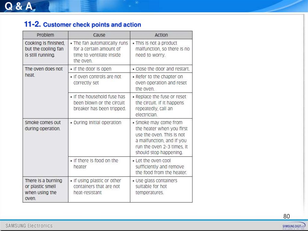
Q&A11-2. Customer check points and action
80
81.
Q&A11-2. Customer check points and action
81
82.
Thank You82