


 Промышленность
Похожие презентации:


Drilling services
1.
Well construction, completion,stimulation services and technologies
2.
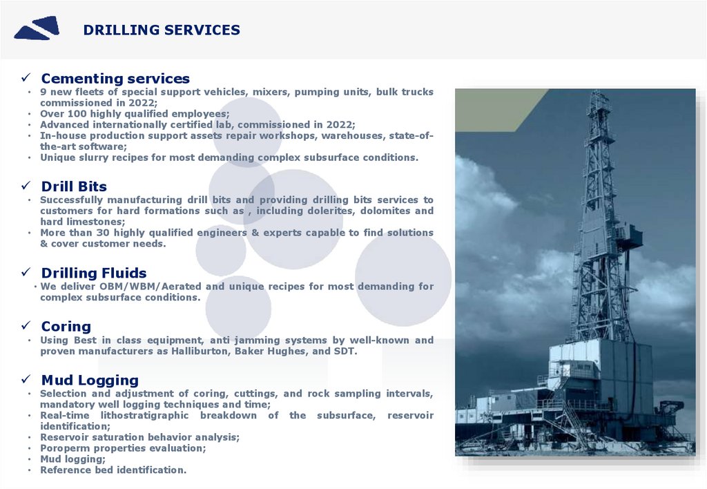
DRILLING SERVICESCementing services
• 9 new fleets of special support vehicles, mixers, pumping units, bulk trucks
commissioned in 2022;
• Over 100 highly qualified employees;
• Advanced internationally certified lab, commissioned in 2022;
• In-house production support assets repair workshops, warehouses, state-ofthe-art software;
• Unique slurry recipes for most demanding complex subsurface conditions.
Drill Bits
• Successfully manufacturing drill bits and providing drilling bits services to
customers for hard formations such as , including dolerites, dolomites and
hard limestones;
• More than 30 highly qualified engineers & experts capable to find solutions
& cover customer needs.
Drilling Fluids
• We deliver OBM/WBM/Aerated and unique recipes for most demanding for
complex subsurface conditions.
Coring
• Using Best in class equipment, anti jamming systems by well-known and
proven manufacturers as Halliburton, Baker Hughes, and SDT.
Mud Logging
• Selection and adjustment of coring, cuttings, and rock sampling intervals,
mandatory well logging techniques and time;
• Real-time lithostratigraphic breakdown of the subsurface, reservoir
identification;
• Reservoir saturation behavior analysis;
• Poroperm properties evaluation;
• Mud logging;
• Reference bed identification.
3.
PRODUCTION CAPABILITIESProduction assets – over 250 CNC (computer numerical controlled)
machineries;
1,500,000 products;
Total workforce – over 1000 highly qualified employees;
Total production area – 50,000 sq. m.;
Quality control staff – 40 experts;
Indoor and outdoor inventory storage facilities – 10,000 sq. m.;
Three-shift operation – 24/7/365.
Annual output – over
4.
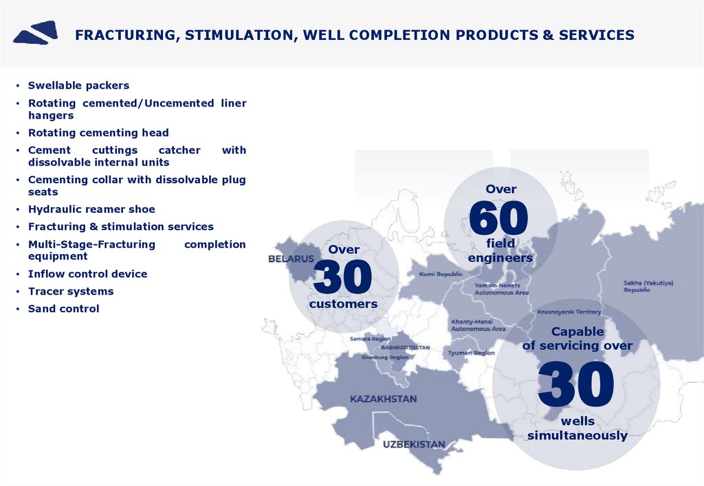
FRACTURING, STIMULATION, WELL COMPLETION PRODUCTS & SERVICES• Swellable packers
• Rotating cemented/Uncemented liner
hangers
• Rotating cementing head
• Cement
cuttings
catcher
dissolvable internal units
with
• Cementing collar with dissolvable plug
seats
Over
• Hydraulic reamer shoe
• Fracturing & stimulation services
• Multi-Stage-Fracturing
equipment
• Inflow control device
• Tracer systems
• Sand control
completion
Over
30
60
field
engineers
customers
Capable
of servicing over
30
wells
simultaneously
5.
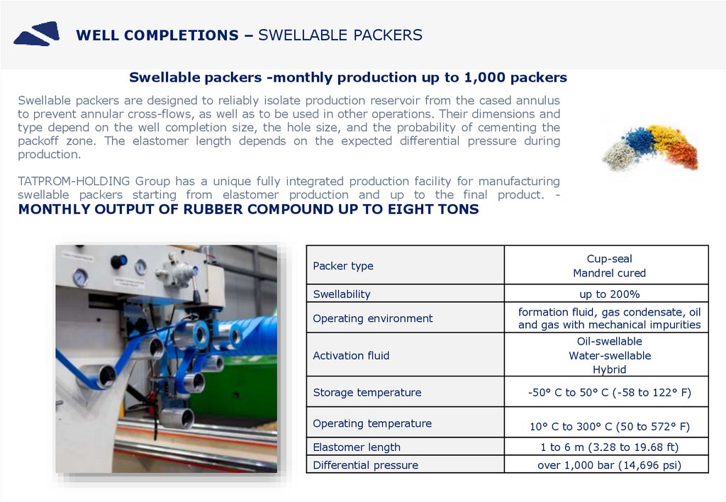
WELL COMPLETIONS – SWELLABLE PACKERSSwellable packers -monthly production up to 1,000 packers
Swellable packers are designed to reliably isolate production reservoir from the cased annulus
to prevent annular cross-flows, as well as to be used in other operations. Their dimensions and
type depend on the well completion size, the hole size, and the probability of cementing the
packoff zone. The elastomer length depends on the expected differential pressure during
production.
TATPROM-HOLDING Group has a unique fully integrated production facility for manufacturing
swellable packers starting from elastomer production and up to the final product. -
MONTHLY OUTPUT OF RUBBER COMPOUND UP TO EIGHT TONS
Packer type
Cup-seal
Mandrel cured
Swellability
up to 200%
Operating environment
Activation fluid
formation fluid, gas condensate, oil
and gas with mechanical impurities
Oil-swellable
Water-swellable
Hybrid
Storage temperature
-50° С to 50° С (-58 to 122° F)
Operating temperature
10° С to 300° С (50 to 572° F)
Elastomer length
1 to 6 m (3.28 to 19.68 ft)
Differential pressure
over 1,000 bar (14,696 psi)
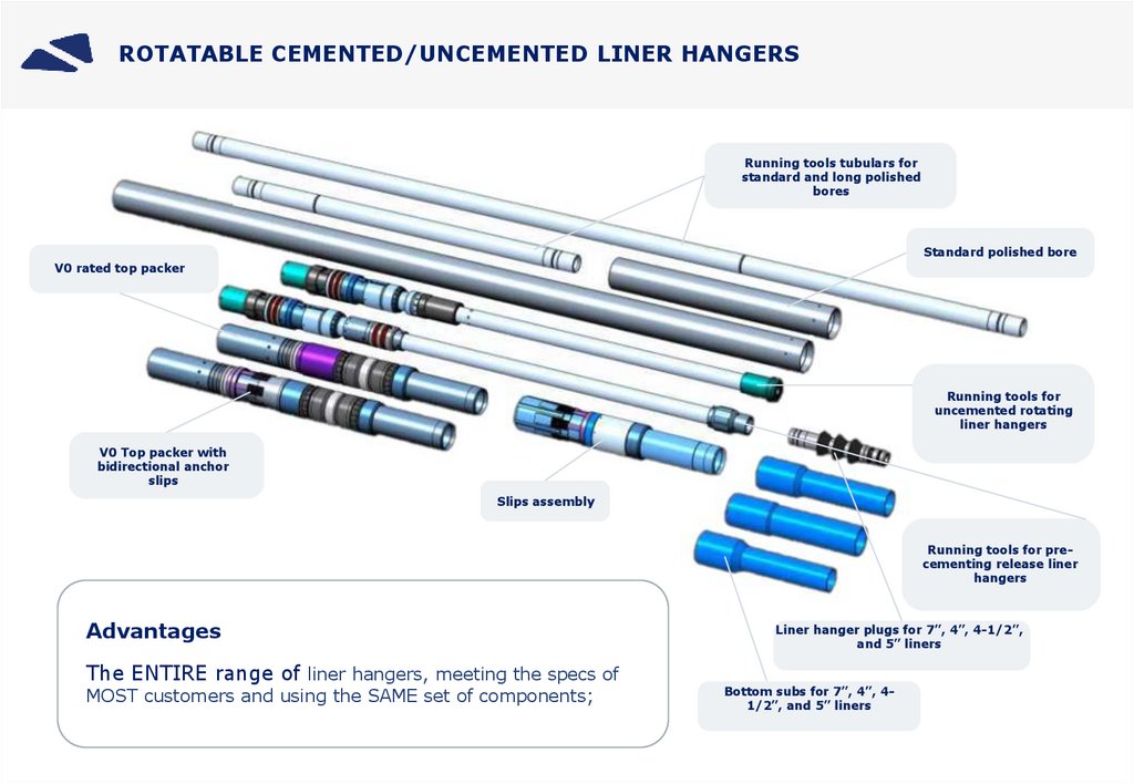
6.
ROTATABLE CEMENTED/UNCEMENTED LINER HANGERSRunning tools tubulars for
standard and long polished
bores
Standard polished bore
V0 rated top packer
Running tools for
uncemented rotating
liner hangers
V0 Top packer with
bidirectional anchor
slips
Slips assembly
Running tools for precementing release liner
hangers
Advantages
The ENTIRE range of liner hangers, meeting the specs of
MOST customers and using the SAME set of components;
Liner hanger plugs for 7”, 4”, 4-1/2”,
and 5” liners
Bottom subs for 7”, 4”, 41/2”, and 5” liners
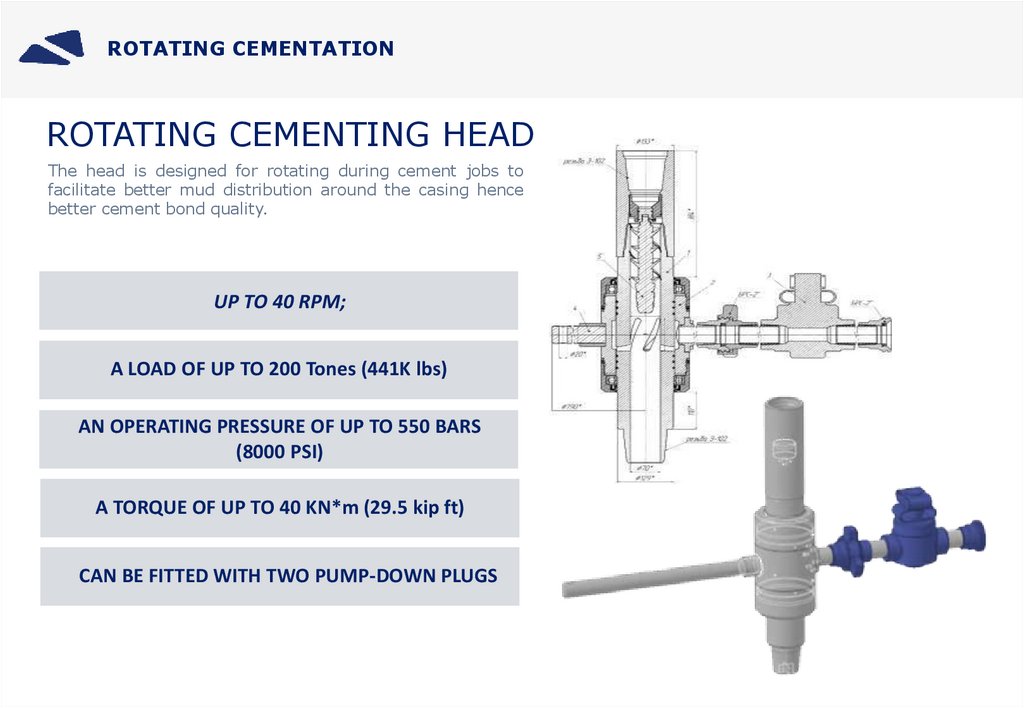
7.
ROTATING CEMENTATIONROTATING CEMENTING HEAD
The head is designed for rotating during cement jobs to
facilitate better mud distribution around the casing hence
better cement bond quality.
UP TO 40 RPM;
A LOAD OF UP TO 200 Tones (441K lbs)
AN OPERATING PRESSURE OF UP TO 550 BARS
(8000 PSI)
A TORQUE OF UP TO 40 KN*m (29.5 kip ft)
CAN BE FITTED WITH TWO PUMP-DOWN PLUGS
8.
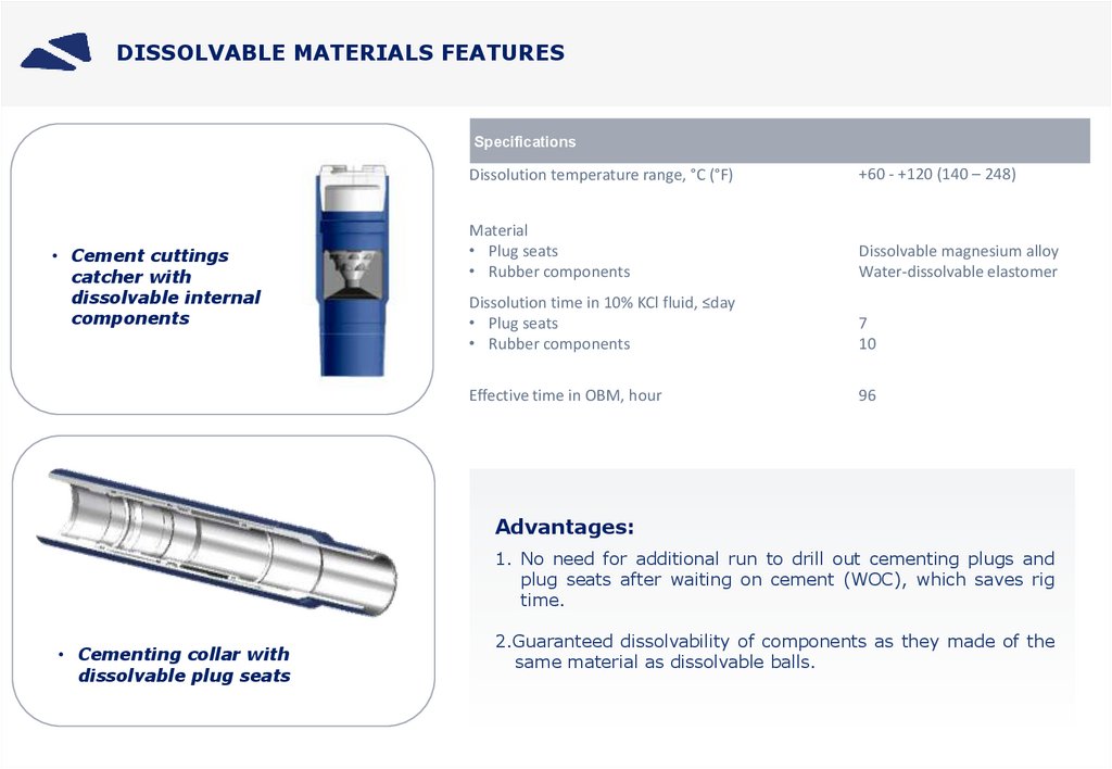
DISSOLVABLE MATERIALS FEATURESSpecifications
• Cement cuttings
catcher with
dissolvable internal
components
Dissolution temperature range, °C (°F)
+60 - +120 (140 – 248)
Material
• Plug seats
• Rubber components
Dissolvable magnesium alloy
Water-dissolvable elastomer
Dissolution time in 10% KCl fluid, ≤day
• Plug seats
• Rubber components
7
10
Effective time in OBM, hour
96
Advantages:
1. No need for additional run to drill out cementing plugs and
plug seats after waiting on cement (WOC), which saves rig
time.
• Cementing collar with
dissolvable plug seats
2.Guaranteed dissolvability of components as they made of the
same material as dissolvable balls.
9.
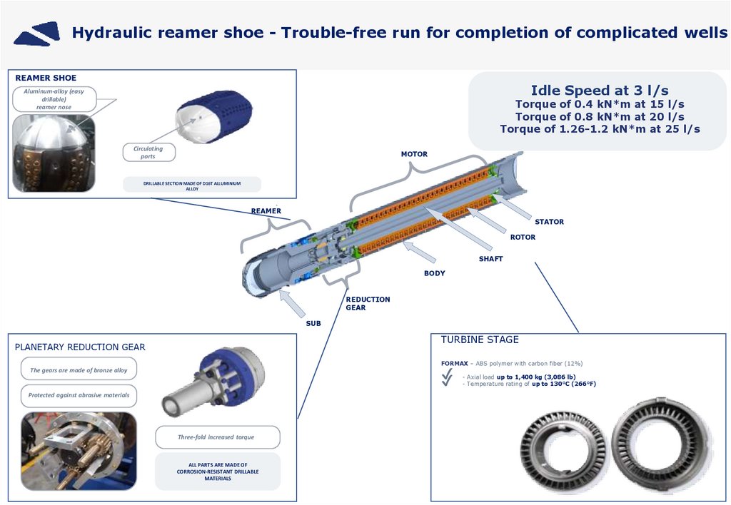
Hydraulic reamer shoe - Trouble-free run for completion of complicated wellsREAMER SHOE
Idle Speed at 3 l/s
Aluminum-alloy (easy
drillable)
reamer nose
Torque of 0.4 kN*m at 15 l/s
Torque of 0.8 kN*m at 20 l/s
Torque of 1.26-1.2 kN*m at 25 l/s
Circulating
ports
MOTOR
DRILLABLE SECTION MADE OF D16T ALLUMINIUM
ALLOY
REAMER
STATOR
ROTOR
SHAFT
BODY
REDUCTION
GEAR
SUB
TURBINE STAGE
PLANETARY REDUCTION GEAR
FORMAX – ABS polymer with carbon fiber (12%)
✔
✔
The gears are made of bronze alloy
Protected against abrasive materials
Three-fold increased torque
ALL PARTS ARE MADE OF
CORROSION-RESISTANT DRILLABLE
MATERIALS
- Axial load up to 1,400 kg (3,086 lb)
- Temperature rating of up to 130°C (266°F)
10.
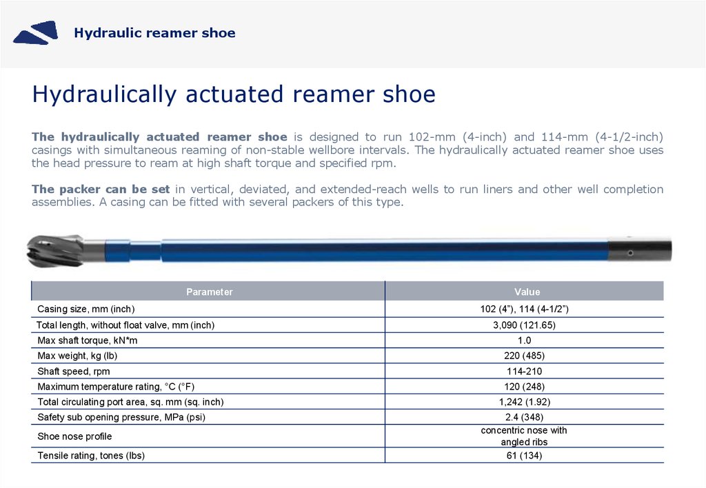
Hydraulic reamer shoeHydraulically actuated reamer shoe
The hydraulically actuated reamer shoe is designed to run 102-mm (4-inch) and 114-mm (4-1/2-inch)
casings with simultaneous reaming of non-stable wellbore intervals. The hydraulically actuated reamer shoe uses
the head pressure to ream at high shaft torque and specified rpm.
The packer can be set in vertical, deviated, and extended-reach wells to run liners and other well completion
assemblies. A casing can be fitted with several packers of this type.
Parameter
Casing size, mm (inch)
Total length, without float valve, mm (inch)
Max shaft torque, kN*m
Value
102 (4”), 114 (4-1/2”)
3,090 (121.65)
1.0
Max weight, kg (lb)
220 (485)
Shaft speed, rpm
114-210
Maximum temperature rating, °C (°F)
120 (248)
Total circulating port area, sq. mm (sq. inch)
1,242 (1.92)
Safety sub opening pressure, MPa (psi)
Shoe nose profile
Tensile rating, tones (lbs)
2.4 (348)
concentric nose with
angled ribs
61 (134)
11.
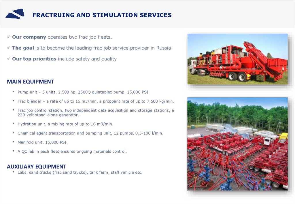
FRACTRUING AND STIMULATION SERVICESOur company operates two frac job fleets.
The goal is to become the leading frac job service provider in Russia
Our top priorities include safety and quality
MAIN EQUIPMENT
• Pump unit – 5 units, 2,500 hp, 2500Q quintuplex pump, 15,000 PSI.
• Frac blender – a rate of up to 16 m3/min, a proppant rate of up to 7,500 kg/min.
• Frac job control station, two independent data acquisition and storage stations, a
220-volt stand-alone generator.
• Hydration unit, a mixing rate of up to 16 m3/min.
• Chemical agent transportation and pumping unit, 12 pumps, 0.5-180 l/min.
• Manifold unit, 15,000 PSI.
• A QC lab in each fleet ensures ongoing materials control.
AUXILIARY EQUIPMENT
• Labs, sand trucks (frac sand trucks), tank farm, staff vehicle etc.
12.
Multi-Stage-Fracturing completion equipment WITH CONTINUOUSCEMENTING CAPABILITY
Ball-drop multi-stage (up to eight stages) frac job tools
with continuous cementing capability
Conductor OD 324 mm (12-3/4 in)
Surface casing OD 244.5 mm (9-5/8 in)
Tapered production casing string to surface OD 178х140 mm
(7x5-1/2 in)
Displacement
cement plug
Stinger
Ball-drop frac sleeve
Frac packer
0 - 8 multi-stage frac ports
Stage
Seat ID, mm (in)
Ball OD, mm (in)
2
79.12 (3-1/8)
81.3 (3-3/16)
3
81.5 (3-3/16)
83.75 (3-5/16)
4
83.95 (3-5/16)
86.27 (3-7/16)
5
86.47 (3-7/16)
88.85 (3-1/2)
6
89.05 (3-9/16)
91.51 (3-5/8)
7
91.71 (3-5/8)
94.24 (3-11/16)
8
94.44 (3-3/4)
97.05 (3-13/16)
Hydraulic frac sleeve
Frac sleeve
13.
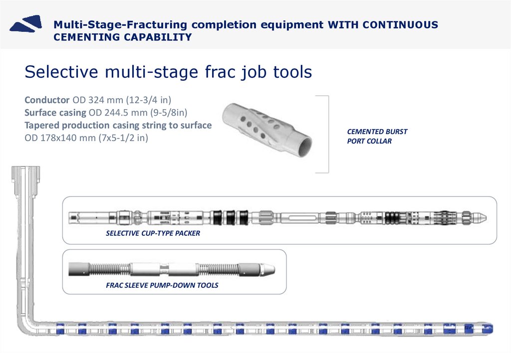
Multi-Stage-Fracturing completion equipment WITH CONTINUOUSCEMENTING CAPABILITY
Selective multi-stage frac job tools
Conductor OD 324 mm (12-3/4 in)
Surface casing OD 244.5 mm (9-5/8in)
Tapered production casing string to surface
OD 178х140 mm (7x5-1/2 in)
SELECTIVE CUP-TYPE PACKER
FRAC SLEEVE PUMP-DOWN TOOLS
CEMENTED BURST
PORT COLLAR
14.
Multi-Stage-Fracturing completion equipment WITH CONTINUOUSCEMENTING CAPABILITY
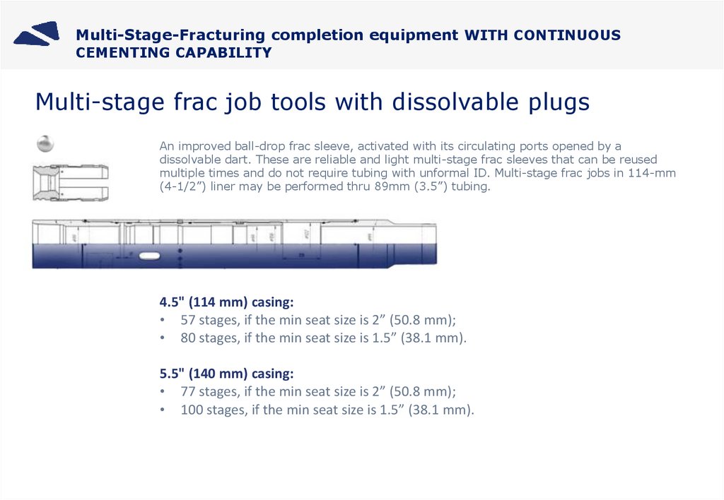
Multi-stage frac job tools with dissolvable plugs
An improved ball-drop frac sleeve, activated with its circulating ports opened by a
dissolvable dart. These are reliable and light multi-stage frac sleeves that can be reused
multiple times and do not require tubing with unformal ID. Multi-stage frac jobs in 114-mm
(4-1/2”) liner may be performed thru 89mm (3.5”) tubing.
4.5" (114 mm) casing:
• 57 stages, if the min seat size is 2” (50.8 mm);
• 80 stages, if the min seat size is 1.5” (38.1 mm).
5.5" (140 mm) casing:
• 77 stages, if the min seat size is 2” (50.8 mm);
• 100 stages, if the min seat size is 1.5” (38.1 mm).
15.
INFLOW CONTROL DEVICESInflow Control Device
(ICD)
This choke valve limits the
reservoir fluid inflow from
high-permeability intervals
while balancing the
wellbore pressure.
Autonomous Inflow Control Device
(AICD)
Autonomous Inflow Control Valve
(AICV)
The negative effects of gas and water
breakthrough are controlled by the lowviscosity high-density fluid flow
(gas, water) creating differential
pressure inside the device (the Bernoulli
Effect), under the influence of which the
movable disk moves upward,
significantly limiting the capacity of the
AICD channels.
The autonomous inflow control valve
features a main inflow and a laminar
flow element (LFE). The
main inflow is fitted with a choke
valve, which position depends on the
pressure drop in the LFE. The
pressure drop is created by the LFE
and the turbulent flow element
(TFE).
Advantages:
Balances inflow;
Balances injection profile*;
Limits inflow of unwanted fluid (water, gas);
Controls of gas and water breakthrough*;
Balances wellbore pressure;
Increases long-term cumulative oil production;
16.
TRACER SYSTEMSTRACER SYSTEM TO IDENTIFY WATER BREAKTHROUGH IN DIFFERENT WELLBORE SECTIONS
Silica-alumina
ceramic proppant
Conductor – 12-3/4”
Water- and oil-degradable
polymer tracer shell
Surface casing size – 9-5/8”
Quantum tracers
Production casing –7”
Wellbore 2
Wellbore –6-1/8”
Perforated pipes –4-1/2”
Space between
screens is filled
with tracers
Wellbore – 6-1/8”
Wellbore 1
Wellbore 3
Swellable packers
✔ Over 60 tracer signatures (codes),
2 tracer signatures = 1 frac stage;
✔ Horizontal, vertical, multi-lateral
wells, sidetracking;
✔ Up to 30 frac stages per well;
✔ Any proppant size, 15 tons at the last
stage of each frac job;
✔ Any number of well tests per
annum.
17.
SAND CONTROLDirect-wire-wrapped screens
Direct-Wire-wrapped slotted screens are consist of ribbed perforated base
pipes with V-shaped wire wrapped around the base pipe. Wire
components are welded to each other, enabling the screen and the
basepipe to act as a single unit.
The filter mesh size varies from 50 to 2,000 microns.
A.
B.
C.
Perforated basepipe
Support profile
V-shaped wire
Advantages of direct-wire-wrapped screens vs conventional screens:
The base pipe and V-shaped wire wrapped around directly to be base pipe, creating an ideal cylinder shape;
No risk of V-shaped wire shifting or getting unwrapped;
Shrink-wrapped support profiles do not need welding;
Increased service life in aggressive downhole environments;
High torque ratings;
High tensile and destruction ratings for tripping in and out;
Fast and simple installation;
Screen sizes of 2-3/8 to 9-5/8 inches;
Strict slot size tolerance (±15 microns);
Ability for reverse circulation;
Screen elements are made of AISI 304, AISI 316 and other steel grades.
18.
SAND CONTROLMECHANICAL INTEGRITY BENCHMARKING: STANDARD SCREEN VS DIRECT-WIRE-WRAPPED SCREEN
Wire-Wrapped Slotted
Screen
Direct-Wire-Wrapped
Screen
Difference
Burst rating, psi
2,100
3,132
a burst rating increase of ~50%
Collapse rating, psi
1,000
5,272
a collapse rating increase of ~500%
Torque rating, lbf.ft
7,200
16,370
a torque rating increase of ~230%, which increases the
operational envelope
Bending limit, deg/100 f
30
45
an increase in short-radius drilling in hydrogen-sulfide
corrosion environment of ~50%
Basepipe flotation, lb*
NA
105,000
Higher chance of competing the job, which becomes
impossible due to the basepipe structure
Specification
*The basepipe flotation measures the strength of wire wrapping around the basepipe and is one of the crucial parameters that determines the
screen mechanical integrity.
THE WELL PRODUCTION PERIOD IN A GREAT EXTEND DEPENDS ON THE SCREEN SLOTS INTEGRITY DURING AND
POST COMPLETION.
19.
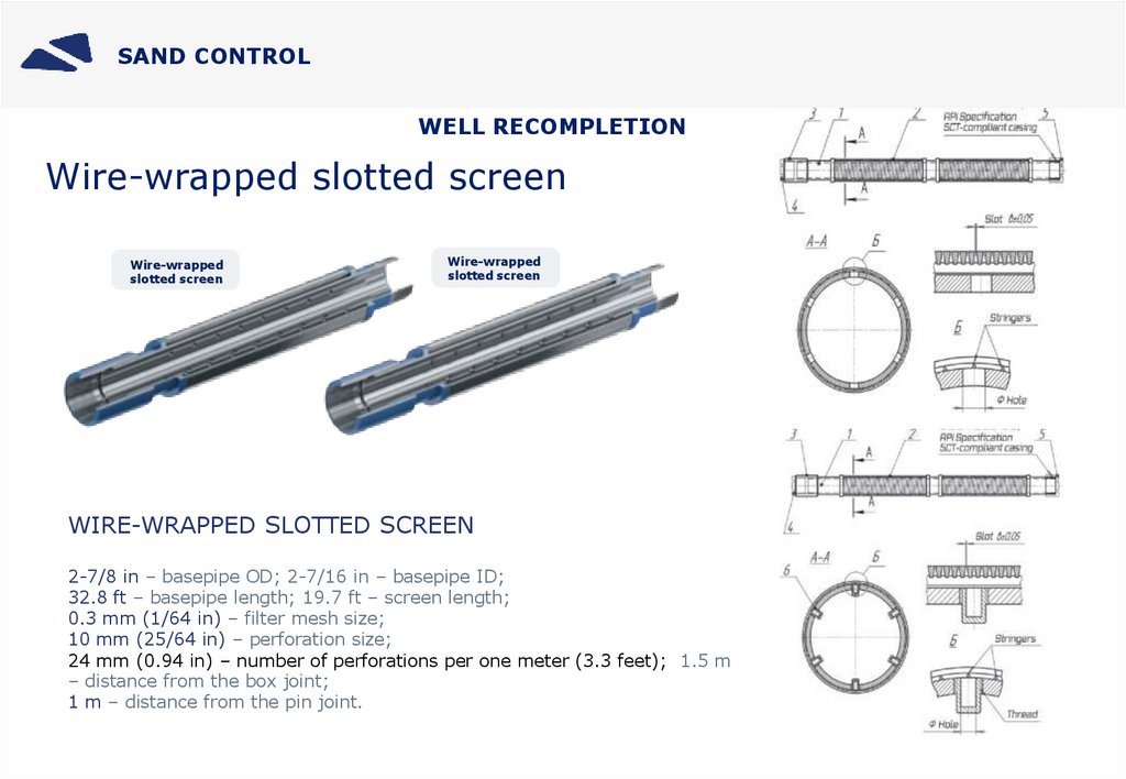
SAND CONTROLWELL RECOMPLETION
Wire-wrapped slotted screen
Wire-wrapped
slotted screen
Wire-wrapped
slotted screen
WIRE-WRAPPED SLOTTED SCREEN
2-7/8 in – basepipe OD; 2-7/16 in – basepipe ID;
32.8 ft – basepipe length; 19.7 ft – screen length;
0.3 mm (1/64 in) – filter mesh size;
10 mm (25/64 in) – perforation size;
24 mm (0.94 in) – number of perforations per one meter (3.3 feet); 1.5 m
– distance from the box joint;
1 m – distance from the pin joint.
20.
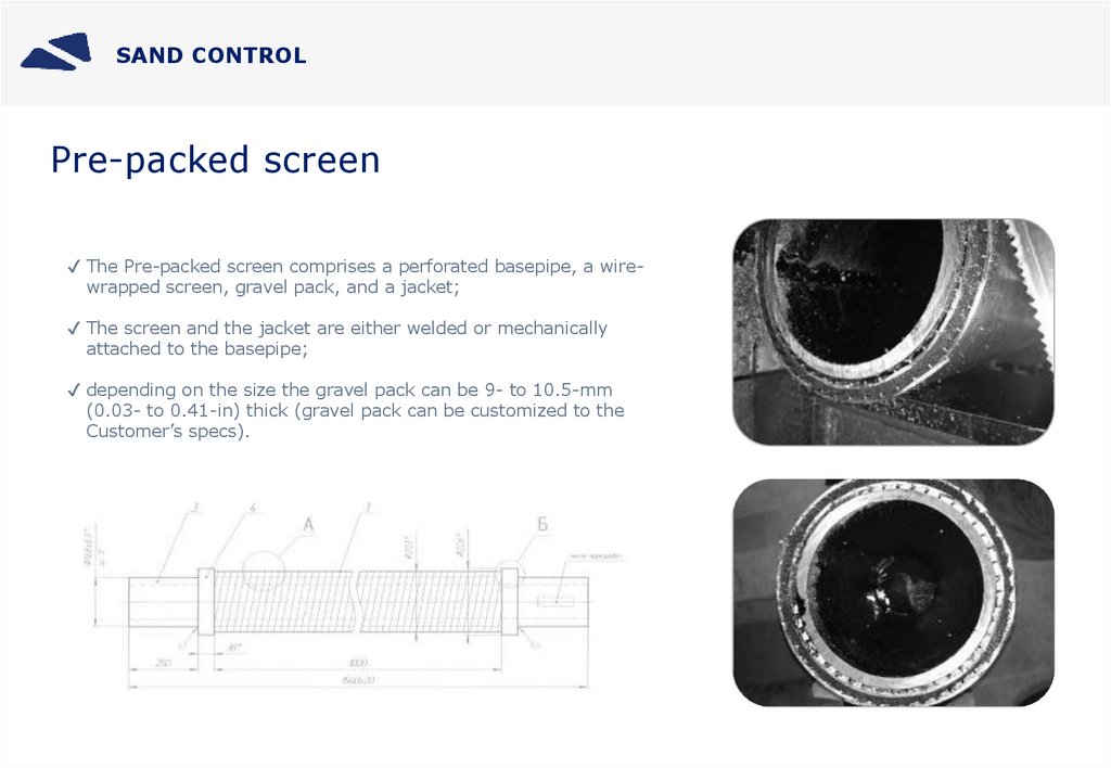
SAND CONTROLPre-packed screen
✔ The Pre-packed screen comprises a perforated basepipe, a wirewrapped screen, gravel pack, and a jacket;
✔ The screen and the jacket are either welded or mechanically
attached to the basepipe;
✔ depending on the size the gravel pack can be 9- to 10.5-mm
(0.03- to 0.41-in) thick (gravel pack can be customized to the
Customer’s specs).
21.
SAND CONTROL – Secondary completion with screens and ICD✔ Inflow control devices will limit water and gas inflow into the wellbore;
✔ Recompletion with inflow control devices helps reactivate some of the inactive wells;
✔ Recompletion with screens reduces solids content of the produced fluid, thus extending ESP’s MTBF;
✔ Inflow control devices will increase cumulative oil production;
✔ Recompletion with inflow control devices improves zone isolation in operating wells, as well as total isolation of
high water cut intervals.
22.
SAND CONTROLDIRECT-WIRE-WRAPPED SCREENS WITH INFLOW CONTROL DEVICES AND TRACER SYSTEMS
Direct-wire-wrapped slotted screens are ribbed perforated basepipes shrink-wrapped with V-shaped wire.
Screen components are welded to each other, enabling the screen and the basepipe to act as a single unit.
Direct-wire-wrapped screens can be fitted with inflow control devices, designed to balance injectivity (inflow)
of a well. They also come equipped with sliding sleeves that close the slots in case of a water (gas)
breakthrough to totally isolate the screened section or during a frac job. At the request of the Customer
direct-wire-wrapped screens can be fitted with a tracer system.