


 Информатика
Похожие презентации:


Filtration the basics and beyond
1.
FILTRATIONTHE BASICS
AND
BEYOND
2.
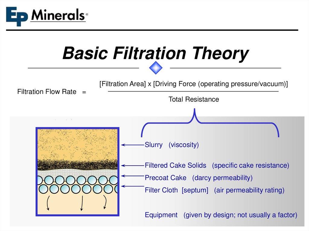
Basic Filtration Theory[Filtration Area] x [Driving Force (operating pressure/vacuum)]
Filtration Flow Rate =
Total Resistance
Slurry (viscosity)
Filtered Cake Solids (specific cake resistance)
Precoat Cake (darcy permeability)
Filter Cloth [septum] (air permeability rating)
Equipment (given by design; not usually a factor)
3.
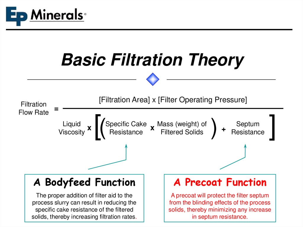
Basic Filtration TheoryFiltration
=
Flow Rate
Liquid
x
Viscosity
[Filtration Area] x [Filter Operating Pressure]
[(
Specific Cake
Mass (weight) of
x
Resistance
Filtered Solids
)
Septum
+ Resistance
]
A Bodyfeed Function
A Precoat Function
The proper addition of filter aid to the
process slurry can result in reducing the
specific cake resistance of the filtered
solids, thereby increasing filtration rates.
A precoat will protect the filter septum
from the blinding effects of the process
solids, thereby minimizing any increase
in septum resistance.
4.
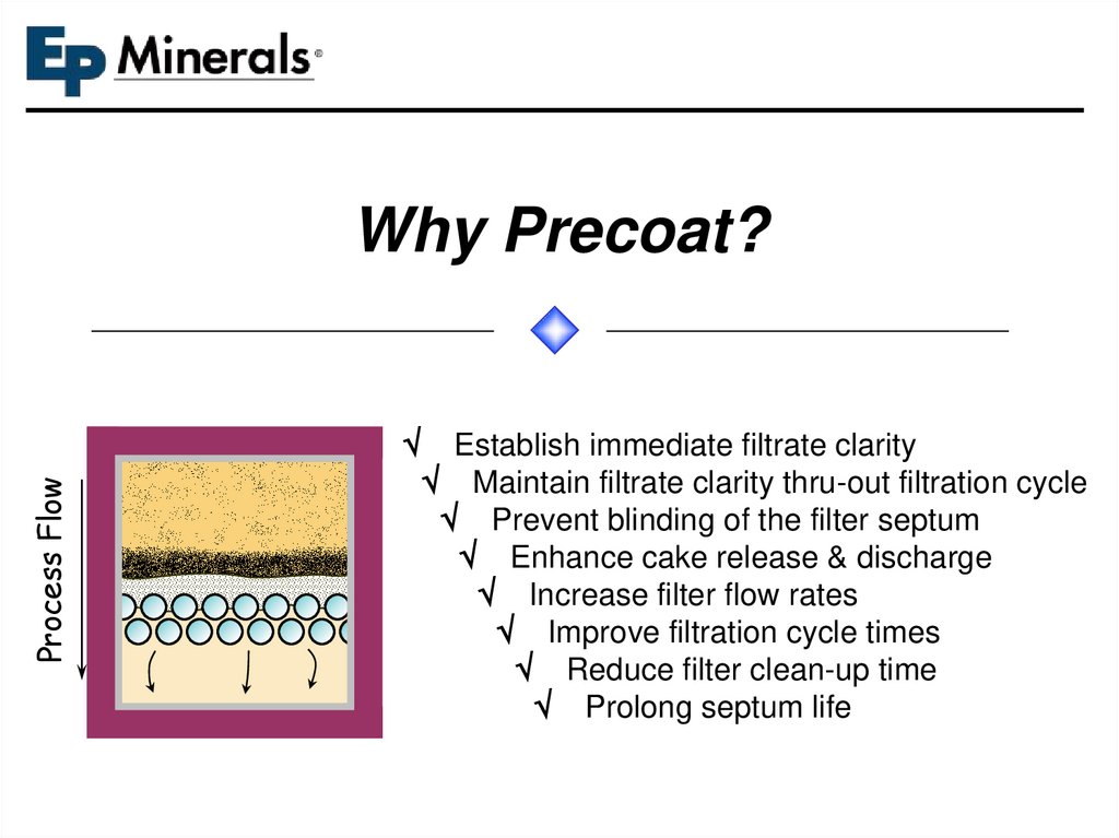
Why Precoat?Process Flow
Establish immediate filtrate clarity
Maintain filtrate clarity thru-out filtration cycle
Prevent blinding of the filter septum
Enhance cake release & discharge
Increase filter flow rates
Improve filtration cycle times
Reduce filter clean-up time
Prolong septum life
5.
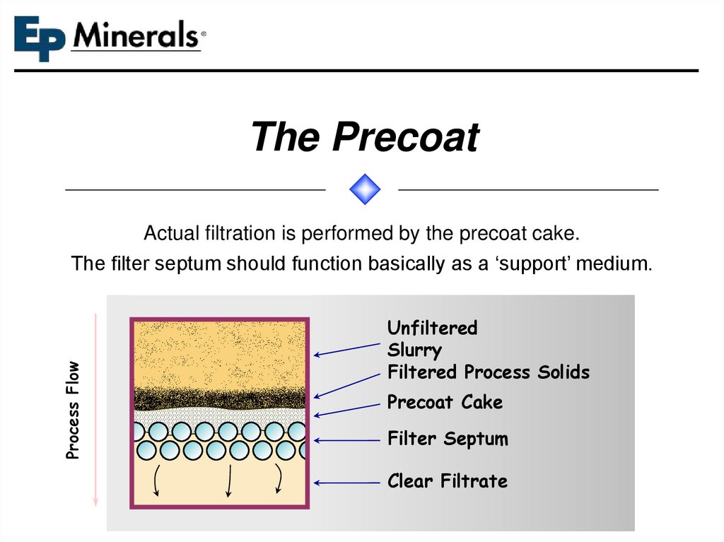
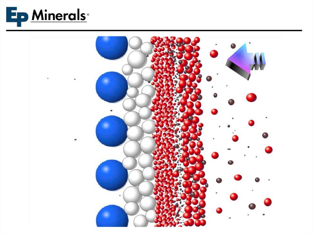
The PrecoatProcess Flow
Actual filtration is performed by the precoat cake.
The filter septum should function basically as a ‘support’ medium.
Unfiltered
Slurry
Filtered Process Solids
Precoat Cake
Filter Septum
Clear Filtrate
6.
THE PRECOAT7.
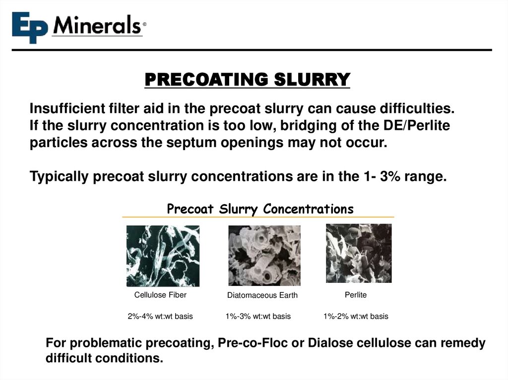
PRECOATING SLURRYInsufficient filter aid in the precoat slurry can cause difficulties.
If the slurry concentration is too low, bridging of the DE/Perlite
particles across the septum openings may not occur.
Typically precoat slurry concentrations are in the 1- 3% range.
Precoat Slurry Concentrations
Cellulose Fiber
Diatomaceous Earth
Perlite
2%-4% wt:wt basis
1%-3% wt:wt basis
1%-2% wt:wt basis
For problematic precoating, Pre-co-Floc or Dialose cellulose can remedy
difficult conditions.
8.
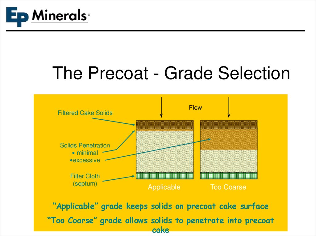
The Precoat - Grade SelectionFlow
Filtered Cake Solids
Solids Penetration
minimal
excessive
Filter Cloth
(septum)
Applicable
Too Coarse
“Applicable” grade keeps solids on precoat cake surface
“Too Coarse” grade allows solids to penetrate into precoat
cake
9.
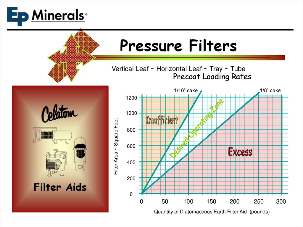
Pressure FiltersVertical Leaf ~ Horizontal Leaf ~ Tray ~ Tube
Precoat Loading Rates
1/16” cake
1/8” cake
1200
Filter Area ~ Square Feet
1000
Filter Aids
800
600
400
200
0
0
50
100
150
200
250
Quantity of Diatomaceous Earth Filter Aid (pounds)
300
10.
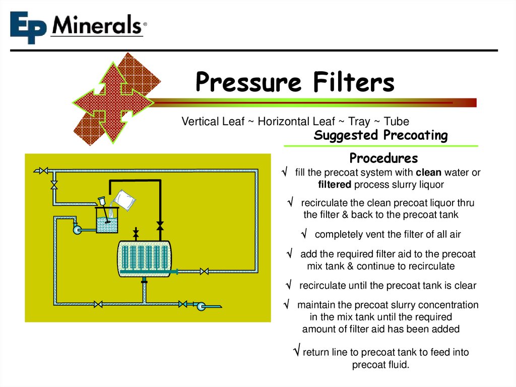
Pressure FiltersVertical Leaf ~ Horizontal Leaf ~ Tray ~ Tube
Suggested Precoating
Procedures
fill the precoat system with clean water or
filtered process slurry liquor
recirculate the clean precoat liquor thru
the filter & back to the precoat tank
completely vent the filter of all air
add the required filter aid to the precoat
mix tank & continue to recirculate
recirculate until the precoat tank is clear
maintain the precoat slurry concentration
in the mix tank until the required
amount of filter aid has been added
return line to precoat tank to feed into
precoat fluid.
11.
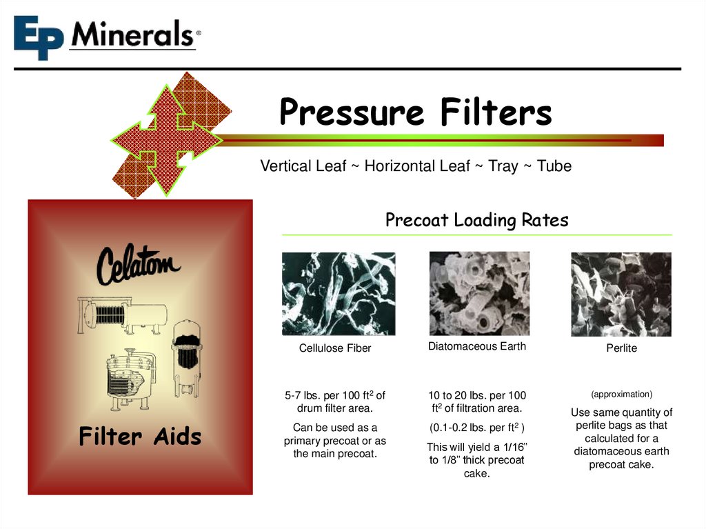
Pressure FiltersVertical Leaf ~ Horizontal Leaf ~ Tray ~ Tube
Precoat Loading Rates
Filter Aids
Cellulose Fiber
Diatomaceous Earth
Perlite
5-7 lbs. per 100 ft2 of
drum filter area.
10 to 20 lbs. per 100
ft2 of filtration area.
(approximation)
Can be used as a
primary precoat or as
the main precoat.
(0.1-0.2 lbs. per ft2 )
This will yield a 1/16”
to 1/8” thick precoat
cake.
Use same quantity of
perlite bags as that
calculated for a
diatomaceous earth
precoat cake.
12.
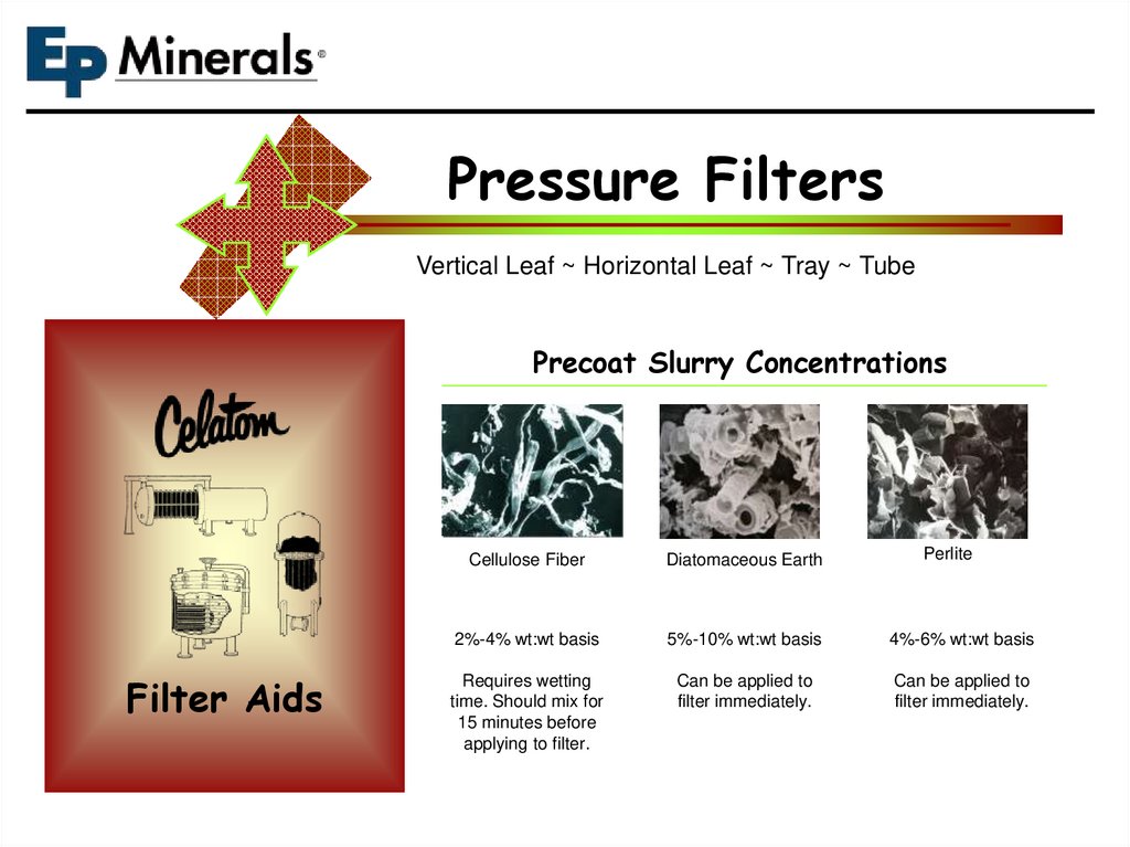
Pressure FiltersVertical Leaf ~ Horizontal Leaf ~ Tray ~ Tube
Precoat Slurry Concentrations
Filter Aids
Perlite
Cellulose Fiber
Diatomaceous Earth
2%-4% wt:wt basis
5%-10% wt:wt basis
4%-6% wt:wt basis
Requires wetting
time. Should mix for
15 minutes before
applying to filter.
Can be applied to
filter immediately.
Can be applied to
filter immediately.
13.
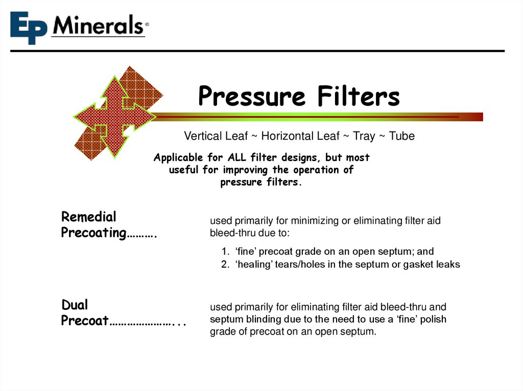
Pressure FiltersVertical Leaf ~ Horizontal Leaf ~ Tray ~ Tube
Applicable for ALL filter designs, but most
useful for improving the operation of
pressure filters.
Remedial
Precoating……….
used primarily for minimizing or eliminating filter aid
bleed-thru due to:
1. ‘fine’ precoat grade on an open septum; and
2. ‘healing’ tears/holes in the septum or gasket leaks
Dual
Precoat…………………...
used primarily for eliminating filter aid bleed-thru and
septum blinding due to the need to use a ‘fine’ polish
grade of precoat on an open septum.
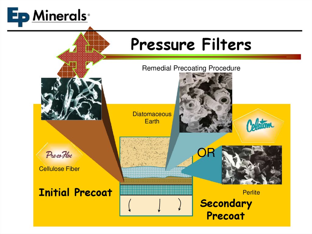
14.
Pressure FiltersRemedial Precoating Procedure
Diatomaceous
Earth
OR
Cellulose Fiber
Initial Precoat
Perlite
Secondary
Precoat
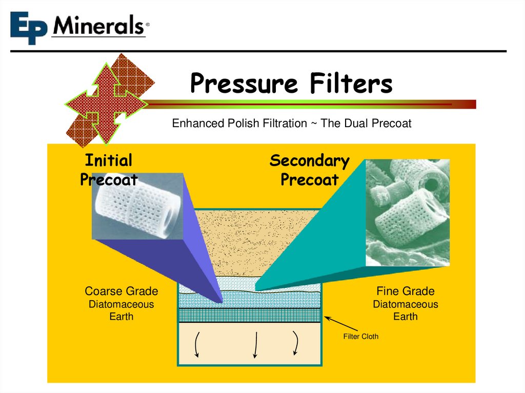
15.
Pressure FiltersEnhanced Polish Filtration ~ The Dual Precoat
Initial
Precoat
Secondary
Precoat
Coarse Grade
Fine Grade
Diatomaceous
Earth
Diatomaceous
Earth
Filter Cloth
16.
The BodyfeedPrimary Function & Process Advantage
Process Slurry
w/Bodyfeed
Filtered Solids
Precoat
Septum
Clear Filtrate
Bodyfeed
Used for controlling the
permeability of the filtered process
solids
(specific cake resistance)
Quantity & grade of bodyfeed can
be adjusted, as required, during the
filtration cycle for optimum filtration
performance.
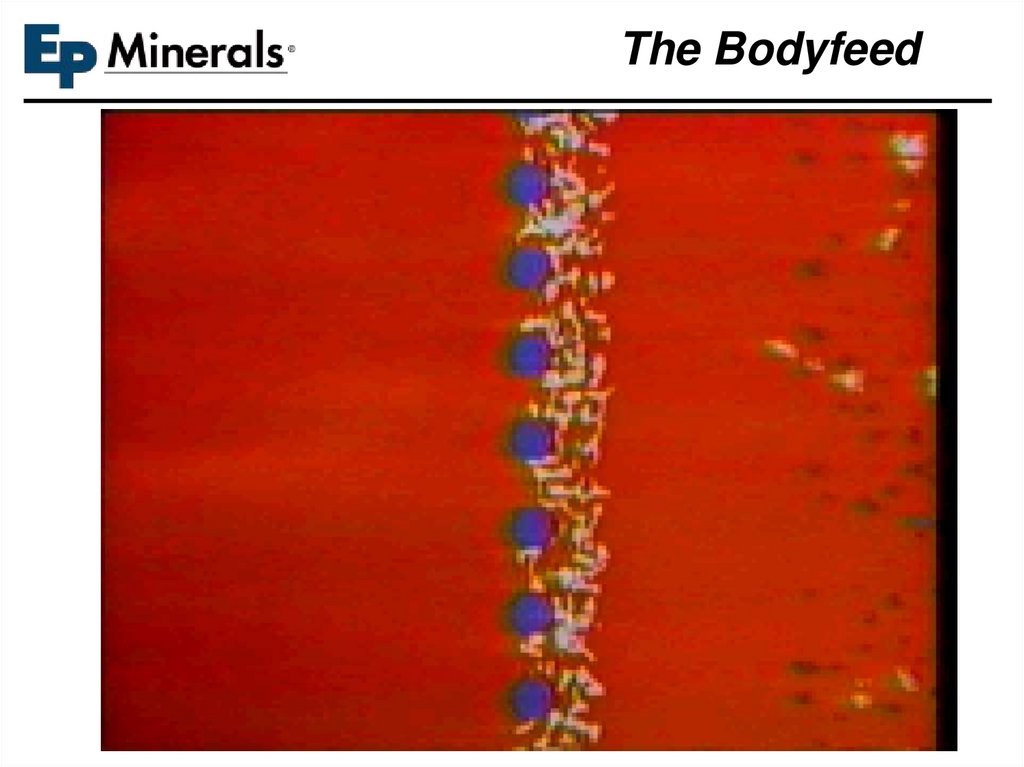
17.
The Bodyfeed18.
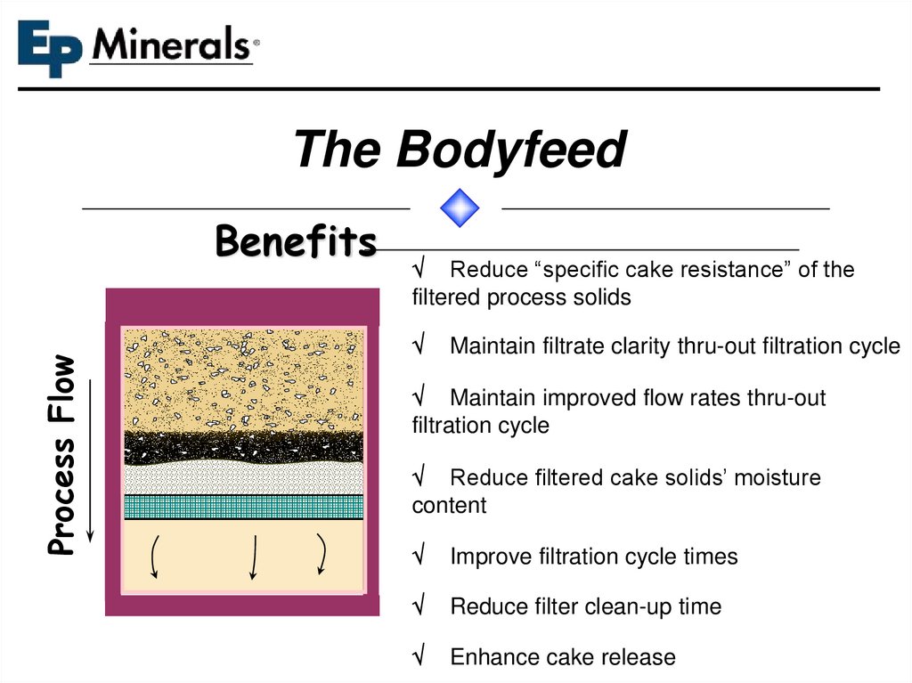
The BodyfeedProcess Flow
Benefits
Reduce “specific cake resistance” of the
filtered process solids
Maintain filtrate clarity thru-out filtration cycle
Maintain improved flow rates thru-out
filtration cycle
Reduce filtered cake solids’ moisture
content
Improve filtration cycle times
Reduce filter clean-up time
Enhance cake release
19.
Bodyfeed Addition RatesProcess Flow
The amount of bodyfeed is a direct function of the amount AND
compressibility of the solids being removed.
General rule of thumb
Easy to filter rigid solids 0.5-1 :1 wt:wt
Semi colloidal solids 2-3:1 wt:wt
Colloidal slimy difficult to filter solids as
high as 10:1 wt:wt
Suggested ‘starting’ dosages. Optimum dosage
determined empirically.
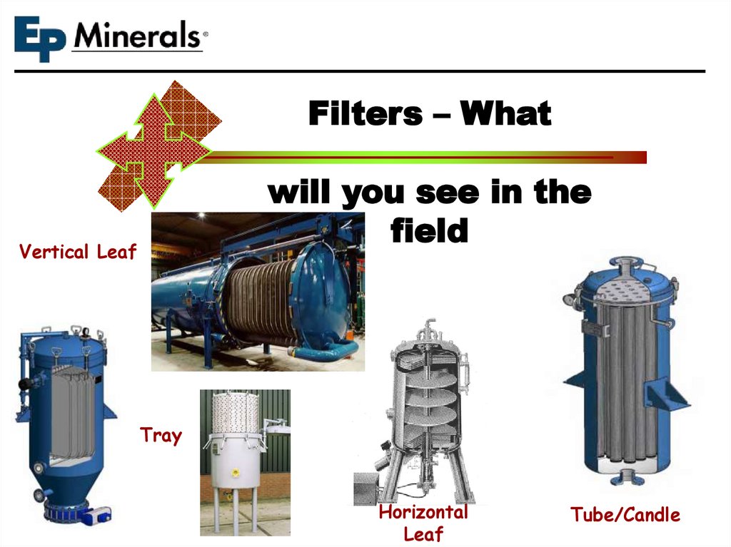
20.
Filters – Whatwill you see in the
field
Vertical Leaf
Tray
Horizontal
Leaf
Tube/Candle
21.
Filters – Whatwill you see in the
field
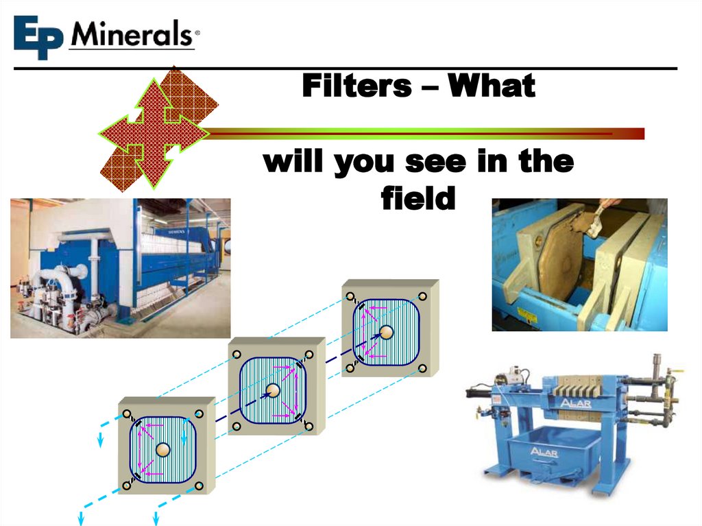
22.
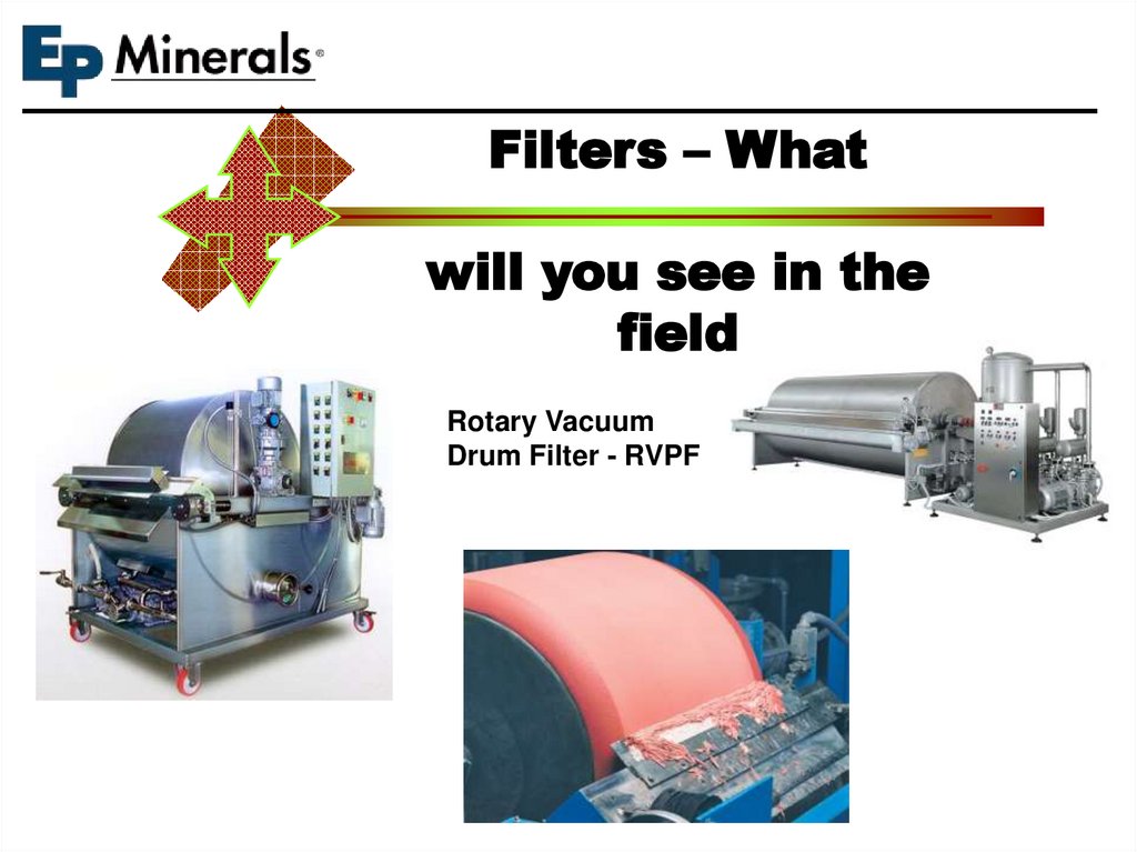
Filters – Whatwill you see in the
field
Rotary Vacuum
Drum Filter - RVPF
23.
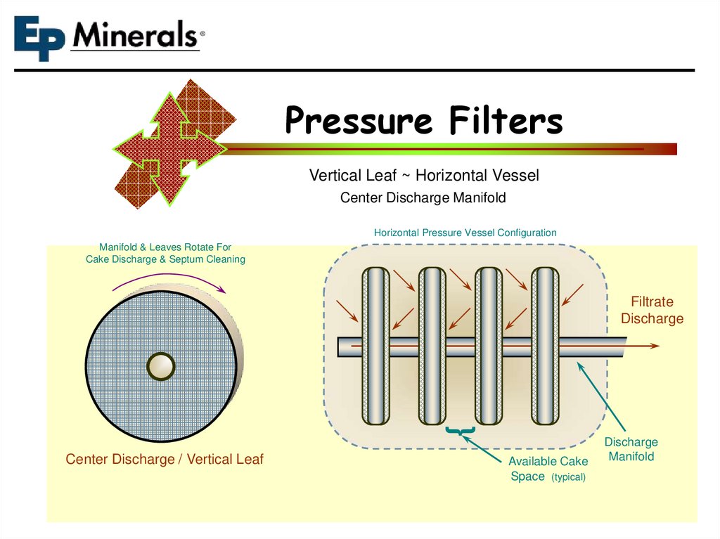
Pressure FiltersVertical Leaf ~ Horizontal Vessel
Center Discharge Manifold
Horizontal Pressure Vessel Configuration
Manifold & Leaves Rotate For
Cake Discharge & Septum Cleaning
{
Filtrate
Discharge
Center Discharge / Vertical Leaf
Available Cake
Space (typical)
Discharge
Manifold
24.
Pressure FiltersVertical Leaf ~ Horizontal Vessel
Bottom Discharge Manifold
Horizontal Pressure Vessel Configuration
Manifold & Leaves Slide Out Of
The Vessel For Cake Discharge
& Septum Cleaning
{
Filtrate
Discharge
Leaf / Manifold Gaskets
Available Cake
Space (typical)
Discharge
Manifold
Vessel Head & Manifold
Separate From Filter Body
For Cake Discharge
25.
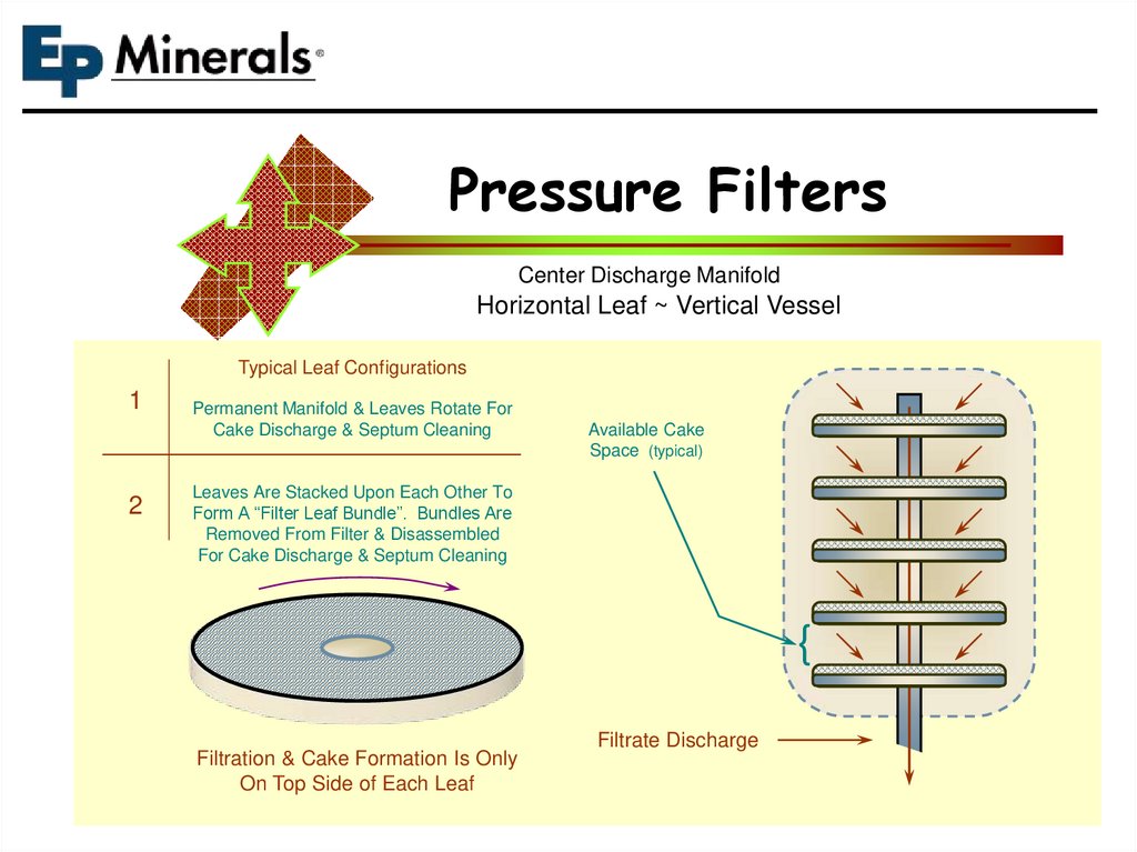
Pressure FiltersCenter Discharge Manifold
Horizontal Leaf ~ Vertical Vessel
Typical Leaf Configurations
1
2
Permanent Manifold & Leaves Rotate For
Cake Discharge & Septum Cleaning
Available Cake
Space (typical)
Leaves Are Stacked Upon Each Other To
Form A “Filter Leaf Bundle”. Bundles Are
Removed From Filter & Disassembled
For Cake Discharge & Septum Cleaning
{
Filtration & Cake Formation Is Only
On Top Side of Each Leaf
Filtrate Discharge
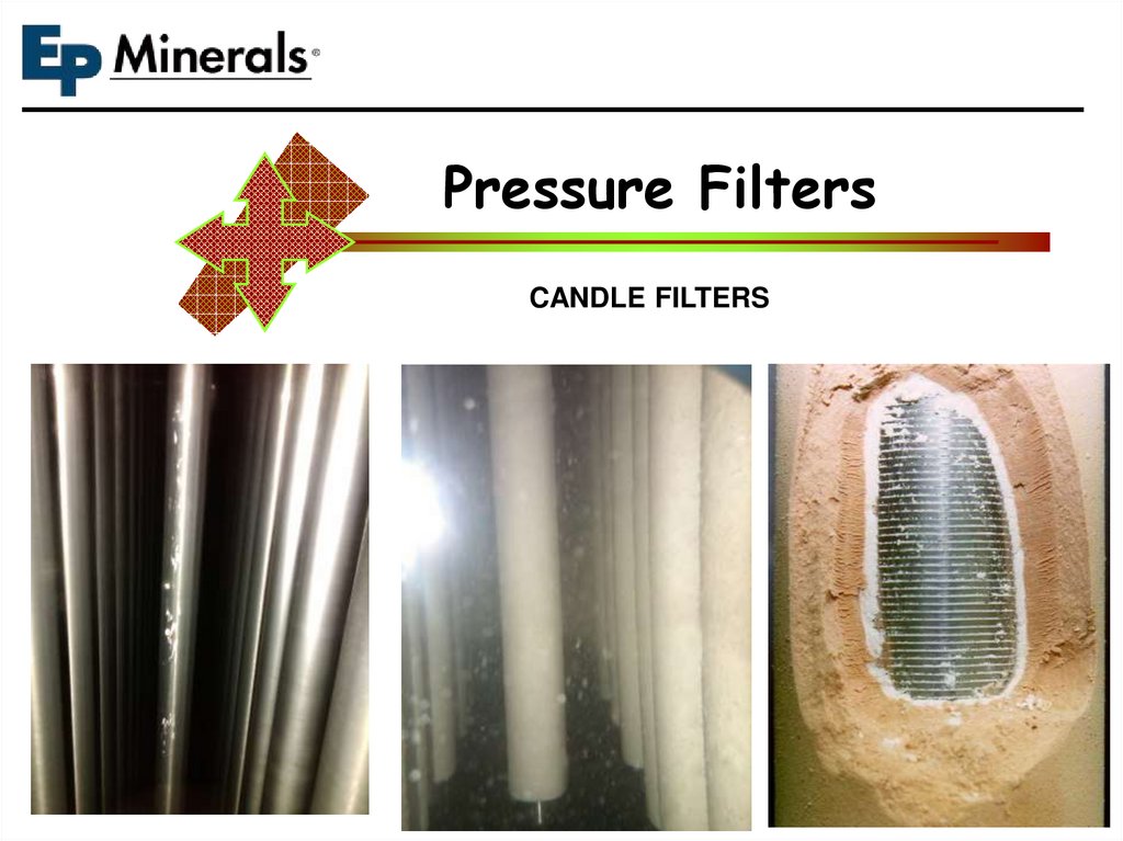
26.
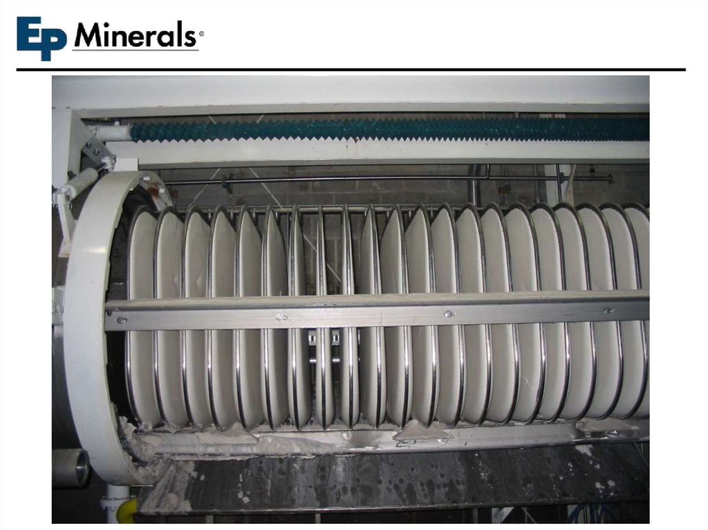
Pressure FiltersCANDLE FILTERS
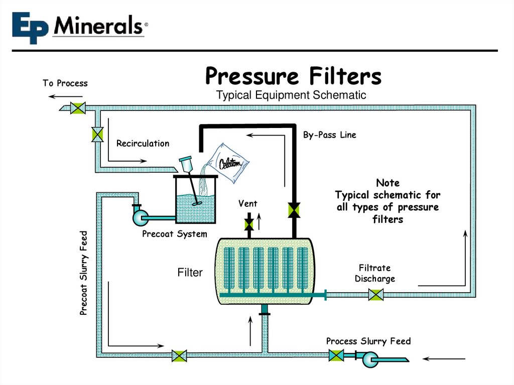
27.
Pressure FiltersTo Process
Typical Equipment Schematic
By-Pass Line
Recirculation
Precoat Slurry Feed
Vent
Note
Typical schematic for
all types of pressure
filters
Precoat System
Filter
Filtrate
Discharge
Process Slurry Feed
28.
Pressure Filters ~ Typical Precoat / Bodyfeed SchematicFiltrate: To “process”, precoat or bodyfeed systems
Bodyfeed ‘make-up’ option:
Filtrate or process slurry
Precoat System
Bodyfeed System
Filtration Device
Process Slurry Feed Pump
29.
Rotary VacuumPrecoat Filter
Precoat
System
Typical Equipment Schematic
Recirculated Filtrate
Process Feed
Vacuum Filter
air
Vacuum
Receiver
Vacuum Pump
Filtrate Pump
seal water
To Process
30.
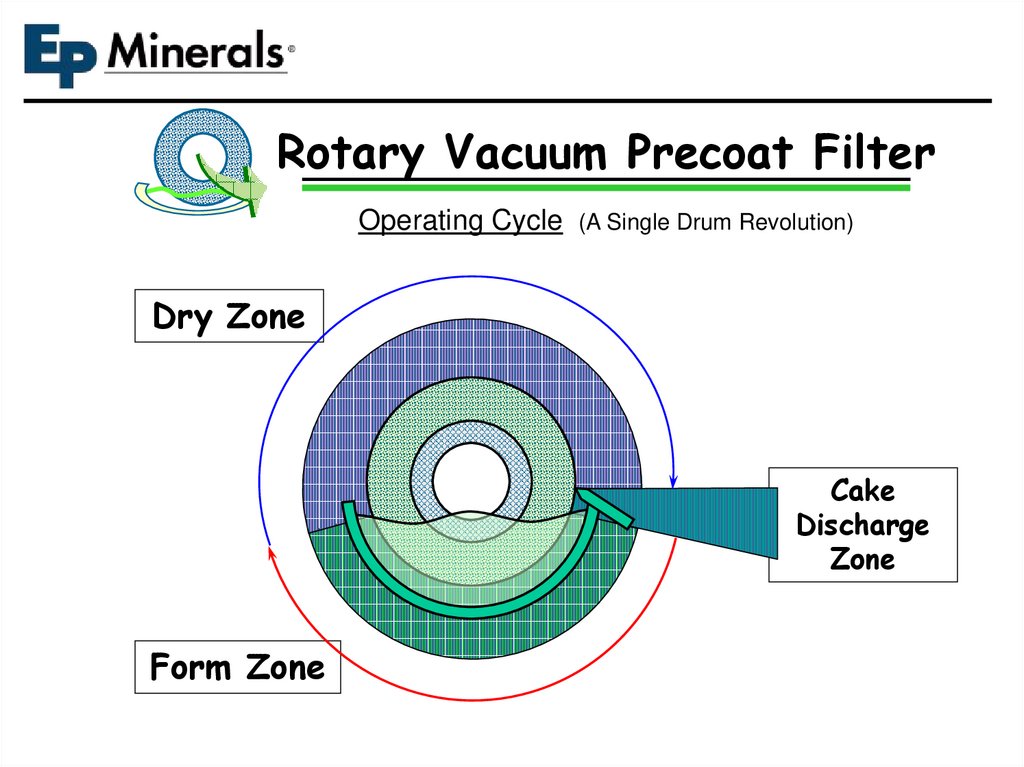
Rotary Vacuum Precoat FilterOperating Cycle (A Single Drum Revolution)
Dry Zone
Cake
Discharge
Zone
Form Zone
31.
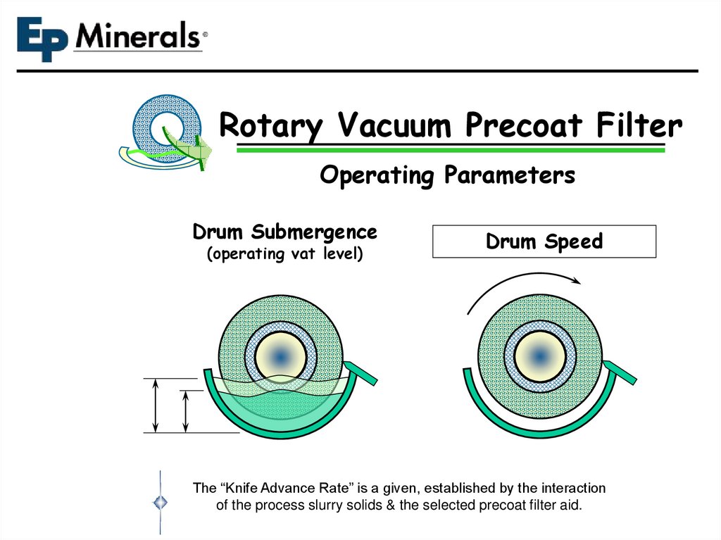
Rotary Vacuum Precoat FilterOperating Parameters
Drum Submergence
(operating vat level)
Drum Speed
The “Knife Advance Rate” is a given, established by the interaction
of the process slurry solids & the selected precoat filter aid.
32.
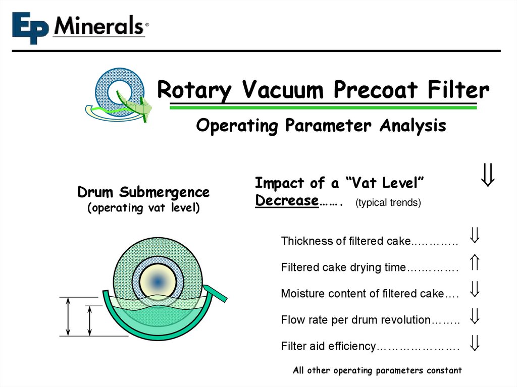
Rotary Vacuum Precoat FilterOperating Parameter Analysis
Drum Submergence
(operating vat level)
Impact of a “Vat Level”
Decrease……. (typical trends)
Thickness of filtered cake..………..
Filtered cake drying time….……….
Moisture content of filtered cake….
Flow rate per drum revolution……..
Filter aid efficiency………………….
All other operating parameters constant
33.
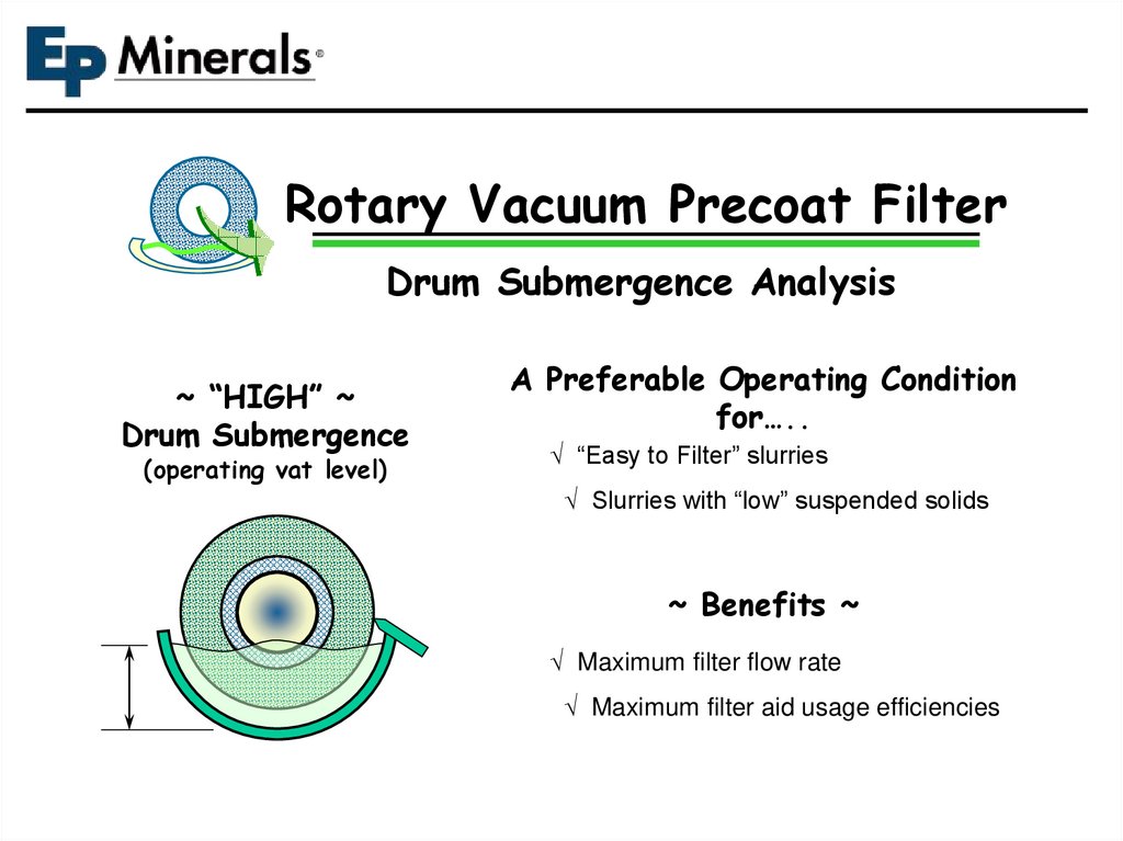
Rotary Vacuum Precoat FilterDrum Submergence Analysis
~ “HIGH” ~
Drum Submergence
(operating vat level)
A Preferable Operating Condition
for…..
“Easy to Filter” slurries
Slurries with “low” suspended solids
~ Benefits ~
Maximum filter flow rate
Maximum filter aid usage efficiencies
34.
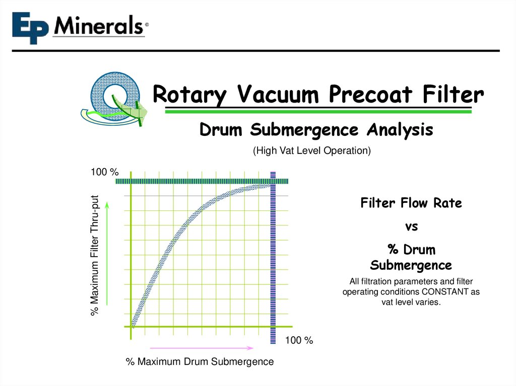
Rotary Vacuum Precoat FilterDrum Submergence Analysis
(High Vat Level Operation)
100 %
% Maximum Filter Thru-put
Filter Flow Rate
vs
% Drum
Submergence
All filtration parameters and filter
operating conditions CONSTANT as
vat level varies.
100 %
% Maximum Drum Submergence
35.
Rotary Vacuum Precoat FilterDrum Submergence Analysis
~ “LOW” ~
Drum Submergence
(operating vat level)
A Preferable Operating Condition
for…..
“Hard to Filter” slurries
Slurries with “high” suspended solids
~ Benefits ~
Improved filtered cake dryness
Improved filtrate recovery
36.
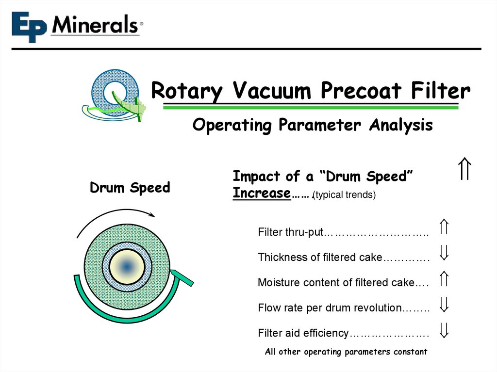
Rotary Vacuum Precoat FilterOperating Parameter Analysis
Drum Speed
Impact of a “Drum Speed”
Increase…….(typical trends)
Filter thru-put………………………..
Thickness of filtered cake………….
Moisture content of filtered cake….
Flow rate per drum revolution……..
Filter aid efficiency………………….
All other operating parameters constant
37.
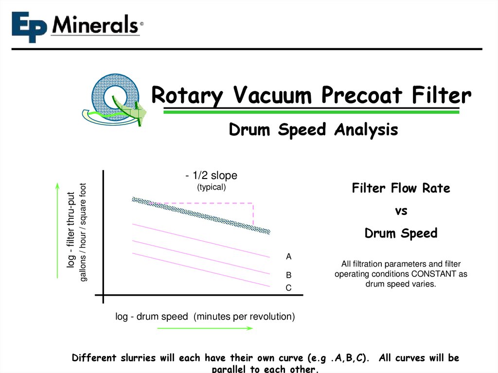
Rotary Vacuum Precoat FilterDrum Speed Analysis
gallons / hour / square foot
log - filter thru-put
- 1/2 slope
Filter Flow Rate
(typical)
vs
Drum Speed
A
B
C
All filtration parameters and filter
operating conditions CONSTANT as
drum speed varies.
log - drum speed (minutes per revolution)
Different slurries will each have their own curve (e.g .A,B,C). All curves will be
parallel to each other.
38.
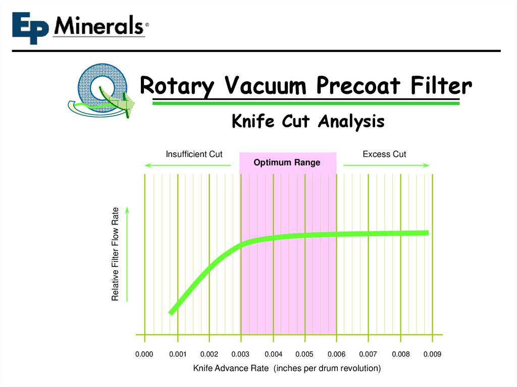
Rotary Vacuum Precoat FilterKnife Cut Analysis
Insufficient Cut
Excess Cut
Relative Filter Flow Rate
Optimum Range
0.000
0.001
0.002
0.003
0.004
0.005
0.006
0.007
Knife Advance Rate (inches per drum revolution)
0.008
0.009
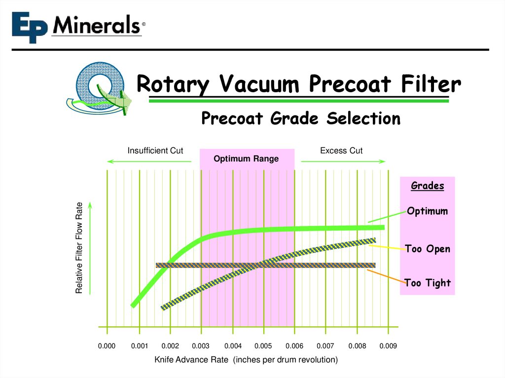
39.
Rotary Vacuum Precoat FilterPrecoat Grade Selection
Insufficient Cut
Excess Cut
Optimum Range
Relative Filter Flow Rate
Grades
Optimum
Too Open
Too Tight
0.000
0.001
0.002
0.003
0.004
0.005
0.006
0.007
Knife Advance Rate (inches per drum revolution)
0.008
0.009
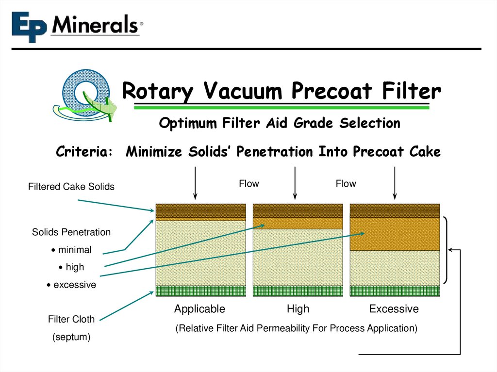
40.
Rotary Vacuum Precoat FilterOptimum Filter Aid Grade Selection
Criteria: Minimize Solids’ Penetration Into Precoat Cake
Flow
Filtered Cake Solids
Flow
Solids Penetration
minimal
high
excessive
Applicable
Filter Cloth
(septum)
High
Excessive
(Relative Filter Aid Permeability For Process Application)
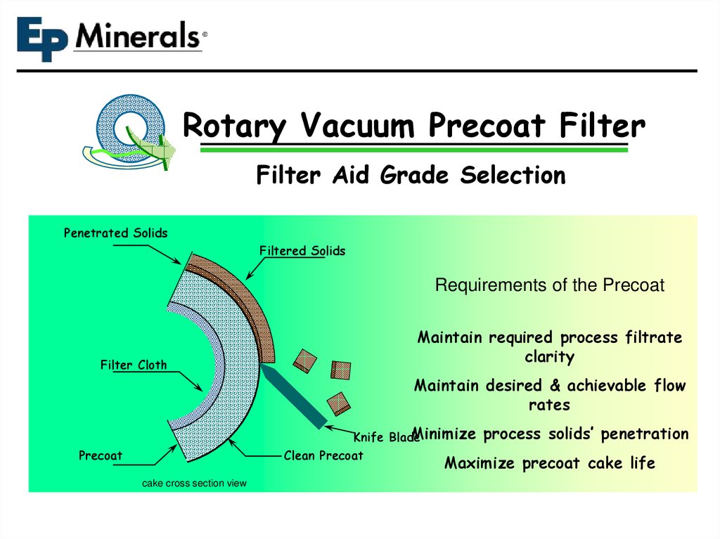
41.
Rotary Vacuum Precoat FilterFilter Aid Grade Selection
Penetrated Solids
Filtered Solids
Requirements of the Precoat
Filter Cloth
Maintain required process filtrate
clarity
Maintain desired & achievable flow
rates
Minimize process solids’ penetration
Knife Blade
Clean Precoat
Precoat
Maximize precoat cake life
cake cross section view
42.
Rotary Vacuum Precoat FilterKnife Cut Analysis
Excessive Knife Advance Rate Per Drum
Revolution
low precoat cake life
Penetrated Solids
I.e knife advance rate greater
than what is optimally required
Filtered Solids
Excess
Precoat
Filter Cloth
low filter aid efficiency
I.e. more filter aid used per
gallon of
slurry than what is
normally required
Precoat
cake cross section view
increased filter aid costs
Knife Blade
increased disposal costs
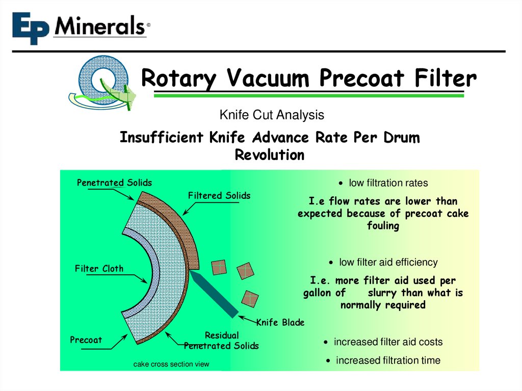
43.
Rotary Vacuum Precoat FilterKnife Cut Analysis
Insufficient Knife Advance Rate Per Drum
Revolution
low filtration rates
Penetrated Solids
Filtered Solids
I.e flow rates are lower than
expected because of precoat cake
fouling
low filter aid efficiency
Filter Cloth
I.e. more filter aid used per
gallon of
slurry than what is
normally required
Knife Blade
Precoat
Residual
Penetrated Solids
cake cross section view
increased filter aid costs
increased filtration time
44.
Rotary Vacuum Precoat FilterKnife Cut Analysis
Optimum Knife Advance Rate Per Drum
Revolution
Penetrated Solids
optimum filtration rates
Filtered Solids
I.e highest possible flow rate for
the given process slurry & filter
settings
optimum filter aid efficiency
Filter Cloth
I.e. lowest filter aid usage for
the quantity of process slurry
filtered
Knife Blade
Precoat
Clean Precoat
cake cross section view
lowest filter aid costs
improved filter utilization
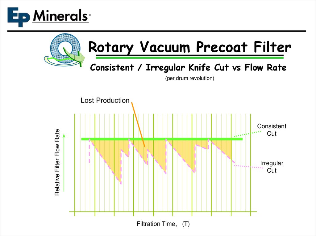
45.
Rotary Vacuum Precoat FilterConsistent / Irregular Knife Cut vs Flow Rate
(per drum revolution)
Lost Production
Relative Filter Flow Rate
Consistent
Cut
Irregular
Cut
Filtration Time, (T)
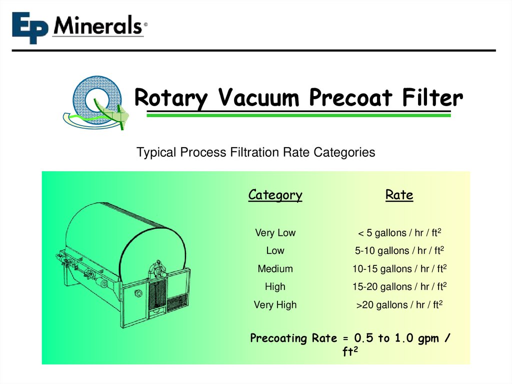
46.
Rotary Vacuum Precoat FilterTypical Process Filtration Rate Categories
Category
Rate
Very Low
< 5 gallons / hr / ft2
Low
5-10 gallons / hr / ft2
Medium
10-15 gallons / hr / ft2
High
15-20 gallons / hr / ft2
Very High
>20 gallons / hr / ft2
Precoating Rate = 0.5 to 1.0 gpm /
ft2
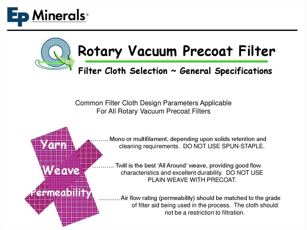
47.
Rotary Vacuum Precoat FilterFilter Cloth Selection ~ General Specifications
Common Filter Cloth Design Parameters Applicable
For All Rotary Vacuum Precoat Filters
Yarn
Weave
……….. Mono or multifilament, depending upon solids retention and
cleaning requirements. DO NOT USE SPUN-STAPLE.
……….. Twill is the best ‘All Around’ weave, providing good flow
characteristics and excellent durability. DO NOT USE
PLAIN WEAVE WITH PRECOAT.
Permeability ……….. Air flow rating (permeability) should be matched to the grade
of filter aid being used in the process. The cloth should
not be a restriction to filtration.
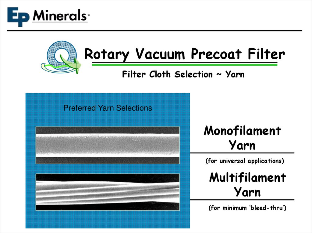
48.
Rotary Vacuum Precoat FilterFilter Cloth Selection ~ Yarn
Preferred Yarn Selections
Monofilament
Yarn
(for universal applications)
Multifilament
Yarn
(for minimum ‘bleed-thru’)
49.
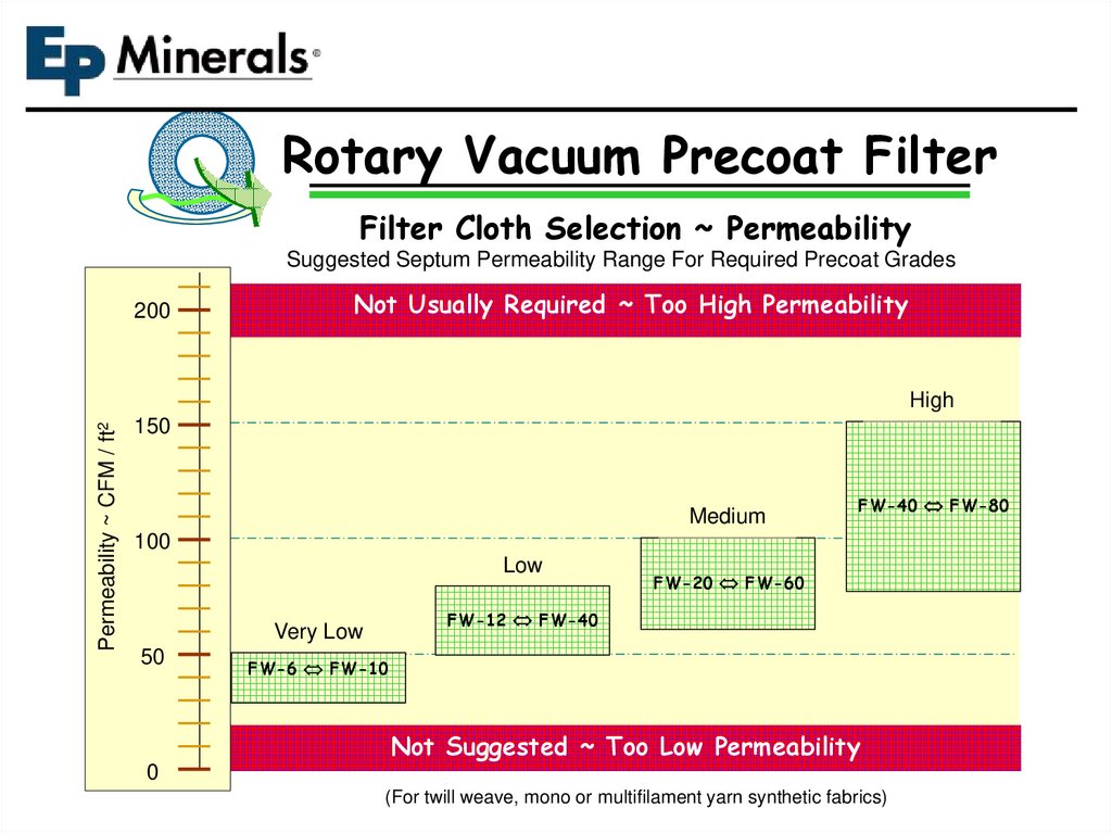
Rotary Vacuum Precoat FilterFilter Cloth Selection ~ Permeability
Suggested Septum Permeability Range For Required Precoat Grades
200
Not Usually Required ~ Too High Permeability
Permeability ~ CFM / ft2
High
150
Medium
FW-40 FW-80
100
Low
FW-12 FW-40
Very Low
50
FW-20 FW-60
FW-6 FW-10
Not Suggested ~ Too Low Permeability
0
(For twill weave, mono or multifilament yarn synthetic fabrics)
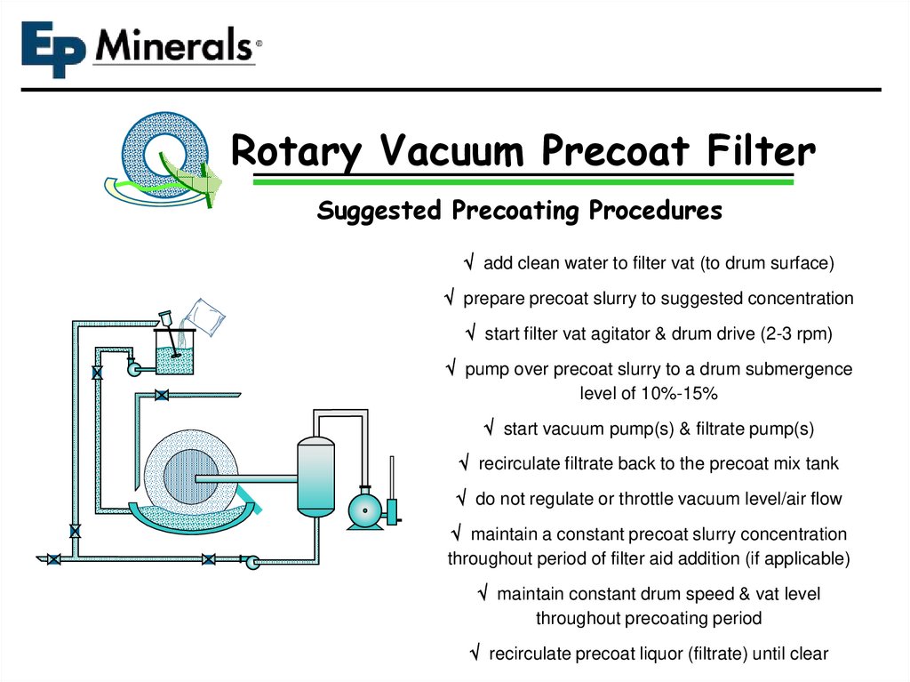
50.
Rotary Vacuum Precoat FilterSuggested Precoating Procedures
add clean water to filter vat (to drum surface)
prepare precoat slurry to suggested concentration
start filter vat agitator & drum drive (2-3 rpm)
pump over precoat slurry to a drum submergence
level of 10%-15%
start vacuum pump(s) & filtrate pump(s)
recirculate filtrate back to the precoat mix tank
do not regulate or throttle vacuum level/air flow
maintain a constant precoat slurry concentration
throughout period of filter aid addition (if applicable)
maintain constant drum speed & vat level
throughout precoating period
recirculate precoat liquor (filtrate) until clear
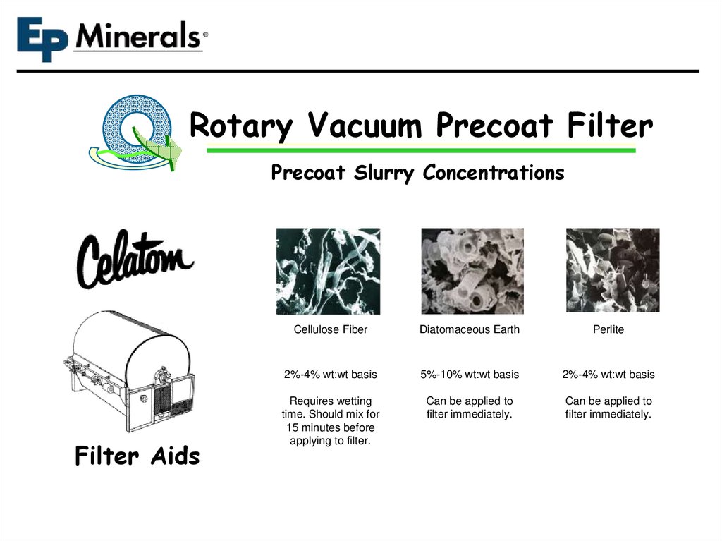
51.
Rotary Vacuum Precoat FilterPrecoat Slurry Concentrations
Filter Aids
Cellulose Fiber
Diatomaceous Earth
Perlite
2%-4% wt:wt basis
5%-10% wt:wt basis
2%-4% wt:wt basis
Requires wetting
time. Should mix for
15 minutes before
applying to filter.
Can be applied to
filter immediately.
Can be applied to
filter immediately.
52.
POISEUILLE’S LAWDr. Jean Louis Poiseuille (1799-1869) found in the 1840’s
-the flow rate of a liquid through a capillary is proportional
to the fourth power of it’s diameter.
This predicts that even small reductions in the size of the
open pores in a filter cake must have a powerful effect on
flow resistance.
For example, a one micron capillary reduced to a 0.9
micron diameter results in only a 10% reduction in size
BUT produces a 34% reduction in the flow rate through
that capillary.
53.
Poiseuille’s law applies to gradation of the differentfilter aids, the finer the grade the lower the
permeability. This is a result of the reduction in the
size of the capillary openings or pore size in the filter
aid.
In actual filtration applications it also applies to flow
rate. As solids plug up the pore volume there are less
capillary openings, so this reduction results in
significant drop in flow rate.
54.
Reducing Cake ResistanceTo counter the effects of Poiseuille’s Law it is key to
form a cake that will have better resistance to
compression than the solids alone. Utilizing a filter aid
with tough, rigid particles and using enough as
bodyfeed to overcome the blinding effect of the solid
matter being removed.
Another key factor is to choose the correct grade so
that the solids removed are captured and help within
the cake and not allowed to migrate further into the
filter cake.
55.
DE Filter AidsNatural Filter Aid
Polish Grade
Calcined Filter Aid
Polish Grade
Flux & Calcined
“Slow” Filter Aid
Flux & Calcined
“Medium” Filter Aid
Flux & Calcined
“Fast” Filter Aid
Grade ~ Darcy Value
Grade ~ Darcy Value
Grade ~ Darcy Value
Grade ~ Darcy Value
Grade ~ Darcy Value
FN-1
0.04
FP-1
0.08
FW-6
0.48
FW-18
1.70
FW-50
3.50
FN-2
0.06
FP-2
0.13
FP-12
1.10
FW-20
2.10
FW-60
5.00
FN-6
0.02
FP-3
0.20
FW-12
0.80
FW-40
3.20
FW-70
7.00
FP-4
0.30
FW-14
1.30
FW-80
9.30
56.
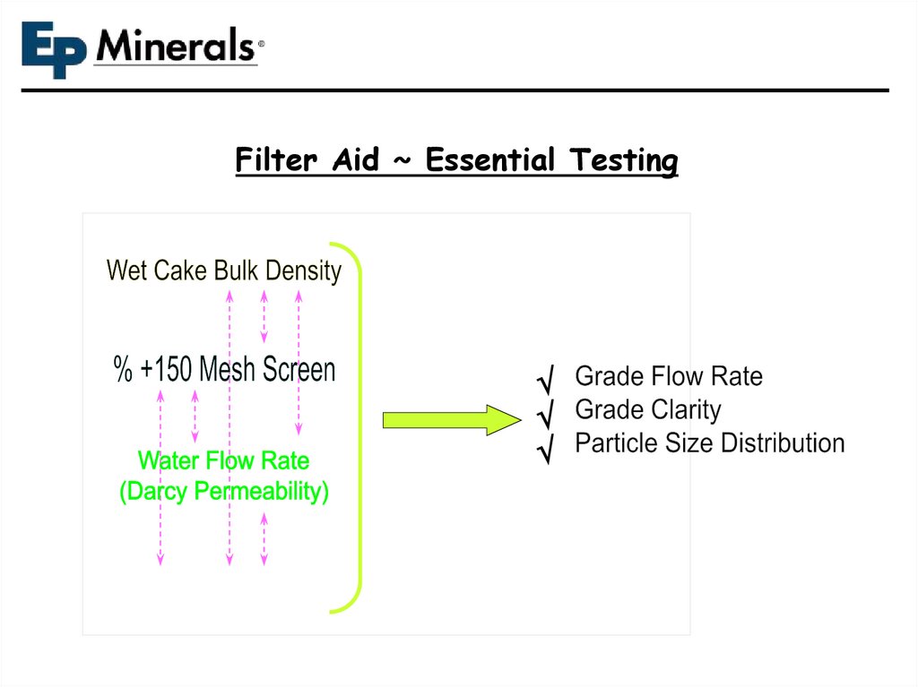
Filter Aid ~ Essential Testing57.
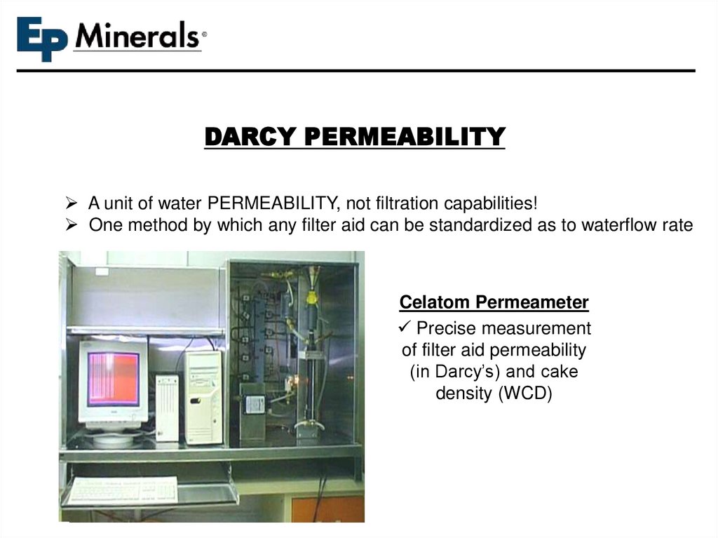
DARCY PERMEABILITYA unit of water PERMEABILITY, not filtration capabilities!
One method by which any filter aid can be standardized as to waterflow rate
Celatom Permeameter
Precise measurement
of filter aid permeability
(in Darcy’s) and cake
density (WCD)
58.
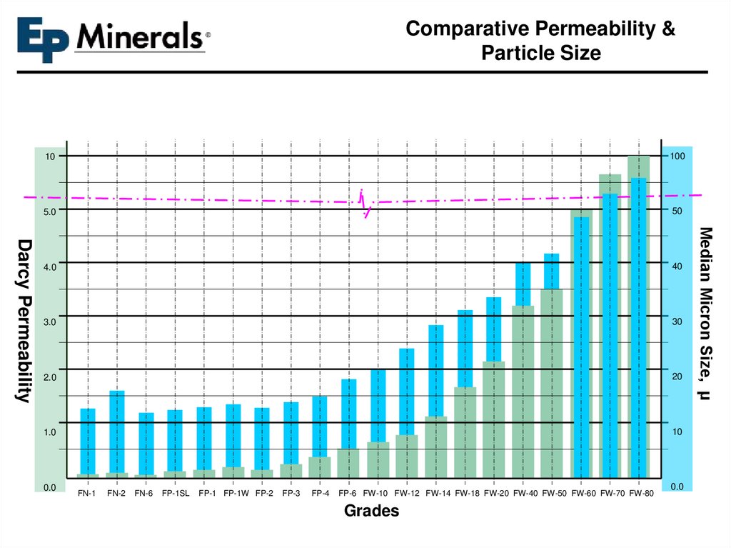
Comparative Permeability &Particle Size
Darcy Permeability
100
5.0
50
4.0
40
3.0
30
2.0
20
1.0
10
0.0
FN-1
FN-2
FN-6
FP-1SL
FP-1 FP-1W FP-2
FP-3
FP-4
FP-6 FW-10 FW-12 FW-14 FW-18 FW-20 FW-40 FW-50 FW-60 FW-70 FW-80
Grades
0.0
Median Micron Size, µ
Darcy Permeability
10
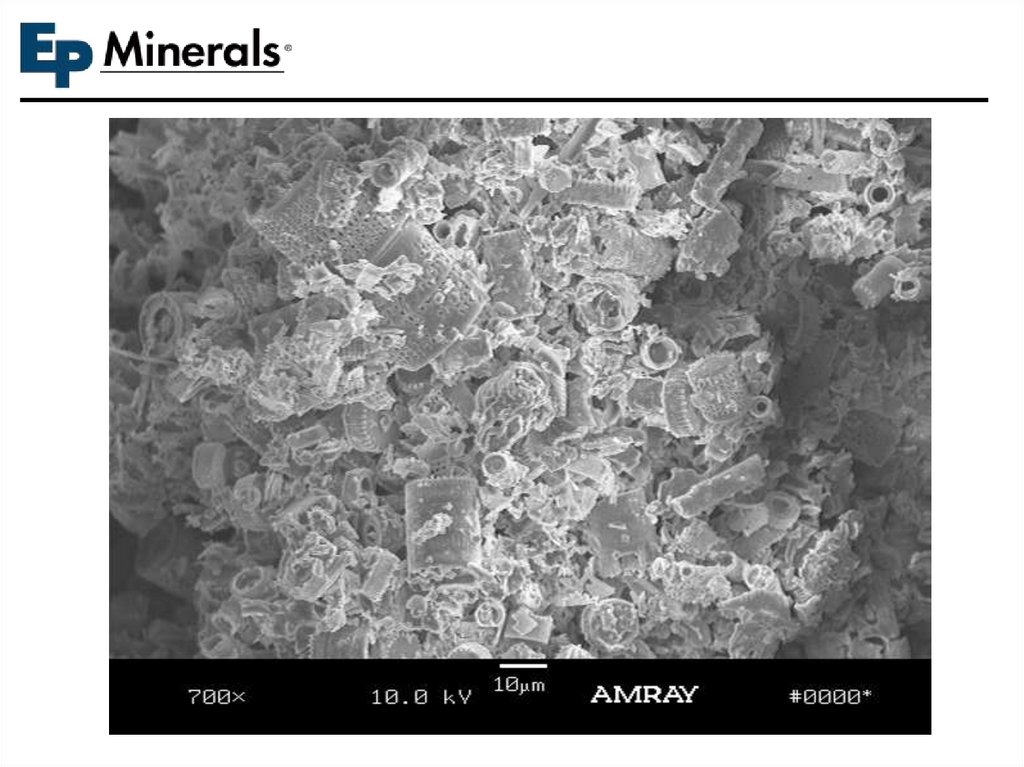
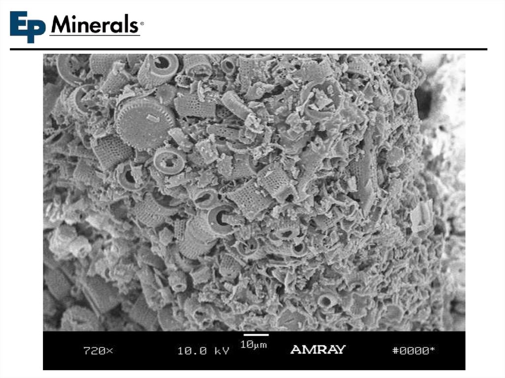
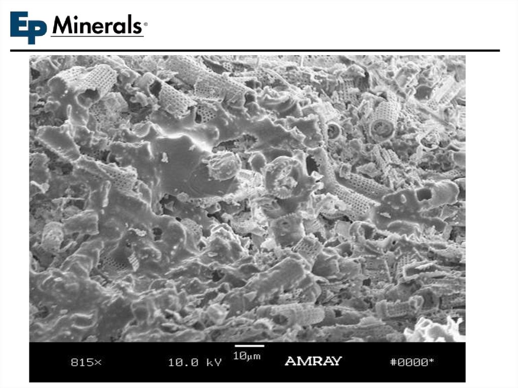
59. Summary: DE is Unique!
• UniqueCharacteristics
– Particle shapes and
Consistency
– Natural / Safe / Pure
– Chemically Inert and
Compatible
– Porosity/Surface Area
– Surface characteristics
– Low density
– Mild Abrasiveness
– Strength
• Unique Versatility
– Filtration
• Engineered
permeability
• Effective (clarity)
• Efficient (speed and
cost)
• Sanitary
60.
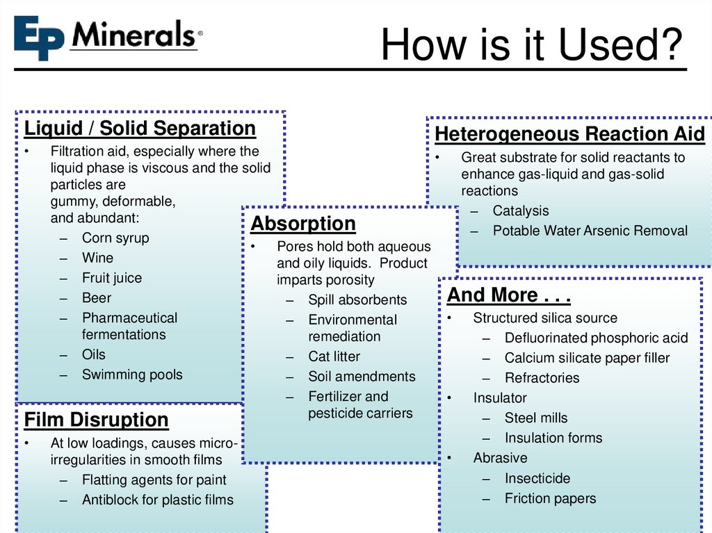
How is it Used?Liquid / Solid Separation
Heterogeneous Reaction Aid
Filtration aid, especially where the
Great substrate for solid reactants to
liquid phase is viscous and the solid
enhance gas-liquid and gas-solid
particles are
reactions
gummy, deformable,
– Catalysis
and abundant:
Absorption
– Potable Water Arsenic Removal
– Corn syrup
Pores hold both aqueous
– Wine
and oily liquids. Product
– Fruit juice
imparts porosity
And More . . .
– Beer
– Spill absorbents
– Pharmaceutical
Structured silica source
– Environmental
fermentations
remediation
– Defluorinated phosphoric acid
– Oils
– Cat litter
– Calcium silicate paper filler
– Swimming pools
– Soil amendments
– Refractories
– Fertilizer and
Insulator
pesticide carriers
– Steel mills
Film Disruption
– Insulation forms
At low loadings, causes micro
Abrasive
irregularities in smooth films
– Insecticide
– Flatting agents for paint
– Friction papers
– Antiblock for plastic films
61. EP Sales By Market Segment
Biodiesel Other4%
Wastewater 2%
4%
Food
4%
Soil
Amendments
1%
Absorbents Coatings
5%
7%
Catalysts
4%
Edible Oil
5%
PE Antiblock
3%
Drilling
1%
Distribution
5%
EP’s market diversity brings resilience
2/3 of business is food and beverage
EP’s Development Focus
Other Additives
6%
Wine /
Juice
8%
Sweeteners
12%
Brewing
8%
Swim Pool
9%
Filtration - 72%
Chemicals
12%
Additives - 20%
Absorbents - 8%
Filter Aids:
Low soluble metals
Ultra-high purity
Enhanced cake stability
Developing better spent cake
solutions
Additives:
Capacity addition
Finer products for high clarity
film applications
Improved packaging
Confidential and proprietary information © 2011 EP Minerals, LLC
62. Light Scattering Efficiency
Reducing gloss requires disrupting the film surface to scatter reflectedlight in different directions. The strong matting efficiency of DE is a
function of its particle size, unique shape, and surface characteristics.
63. What is an “Antiblock”?
Antiblocks (AB) are typically minerals that areused to prevent “blocking” in plastic film.
Blocking is when film sheets adhere to one
another, due to static charge and other factors.
Antiblock additives reduce the tendency for
sheets to block by interrupting the smooth film
surface and reducing the film-to-film contact
surface area.
1 mil
(25 μm)
Confidential and proprietary information © 2007 EPM, LLC
64. Some of Our Customers
65.
66.
67.
68.
69.
70.
71.
72.
73.
74.
75.
76.
77.
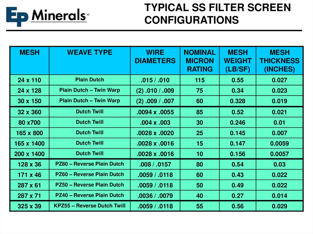
TYPICAL SS FILTER SCREENCONFIGURATIONS
MESH
WEAVE TYPE
WIRE
DIAMETERS
NOMINAL
MICRON
RATING
MESH
WEIGHT
(LB/SF)
MESH
THICKNESS
(INCHES)
24 x 110
Plain Dutch
.015 / .010
115
0.55
0.027
24 x 128
Plain Dutch – Twin Warp
(2) .010 / .009
75
0.34
0.023
30 x 150
Plain Dutch – Twin Warp
(2) .009 / .007
60
0.328
0.019
32 x 360
Dutch Twill
.0094 x .0055
85
0.52
0.021
80 x700
Dutch Twill
.004 x .003
30
0.246
0.01
165 x 800
Dutch Twill
.0028 x .0020
25
0.145
0.007
165 x 1400
Dutch Twill
.0028 x .0016
15
0.147
0.0059
200 x 1400
Dutch Twill
.0028 x .0016
10
0.156
0.0057
128 x 36
PZ80 – Reverse Plain Dutch
.008 / .0157
80
0.54
0.03
171 x 46
PZ60 – Reverse Plain Dutch
.0059 / .0118
60
0.43
0.022
287 x 61
PZ50 – Reverse Plain Dutch
.0059 / .0118
50
0.49
0.022
287 x 71
PZ40 – Reverse Plain Dutch
.0036 / .0079
40
0.27
0.014
325 x 39
KPZ55 – Reverse Dutch Twill
.0059 / .0118
55
0.56
0.029
78.
79.
80.
81.
82.
83.
84.
85.
86.
87.
88.
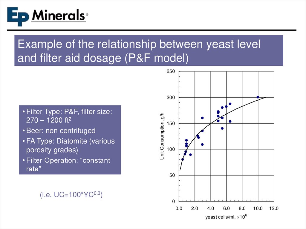
Example of the relationship between yeast leveland filter aid dosage (P&F model)
250
• Filter Type: P&F, filter size:
270 – 1200 ft2
• Beer: non centrifuged
• FA Type: Diatomite (various
porosity grades)
• Filter Operation: “constant
rate”
Unit Consumption, g/hl
200
150
100
50
(i.e. UC=100*YC0.3)
0
0.0
2.0
4.0
6.0
8.0
yeast cells/ml, ×106
10.0
12.0
89.
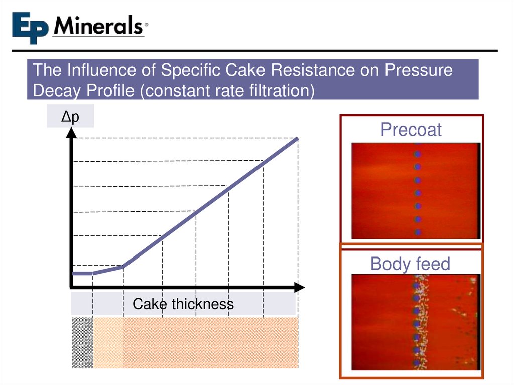
The Influence of Specific Cake Resistance on PressureDecay Profile (constant rate filtration)
Δp
Precoat
Body feed
Cake thickness
90.
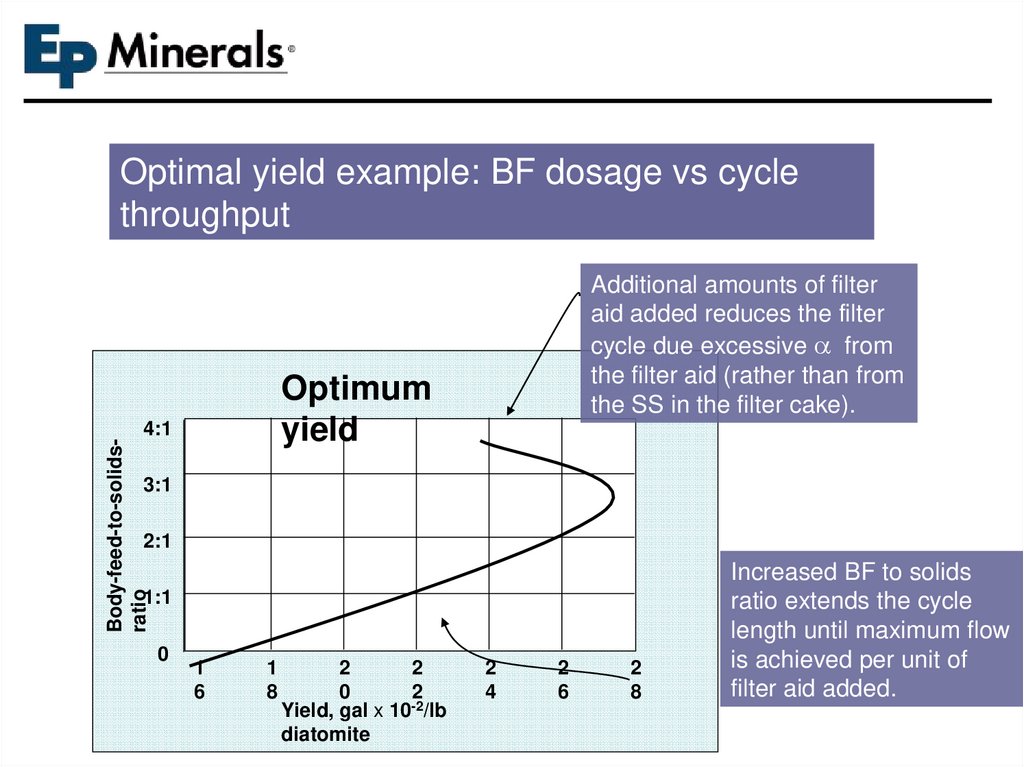
Optimal yield example: BF dosage vs cyclethroughput
Additional amounts of filter
aid added reduces the filter
cycle due excessive a from
the filter aid (rather than from
the SS in the filter cake).
Optimum
yield
Body-feed-to-solidsratio
4:1
3:1
2:1
1:1
0
1
6
1
8
2
2
0
2
Yield, gal x 10-2/lb
diatomite
2
4
2
6
2
8
Increased BF to solids
ratio extends the cycle
length until maximum flow
is achieved per unit of
filter aid added.
91.
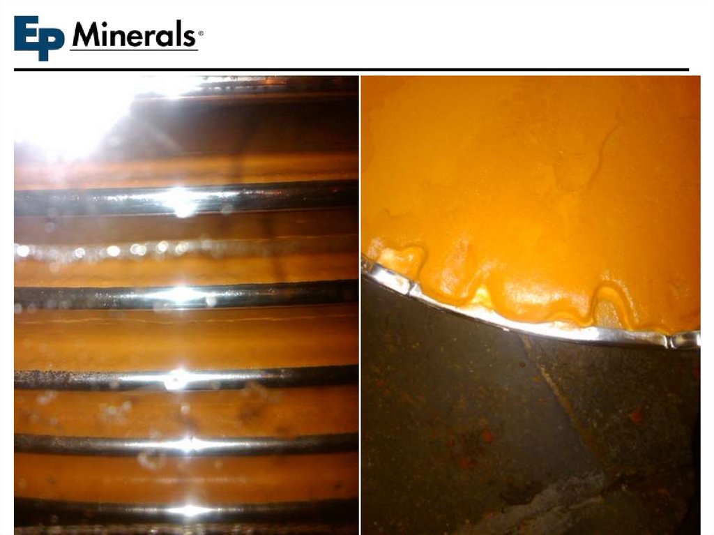
FILTRATION ISSUES92.
Pressure FiltersBy-Pass Line
Unfiltered precoat slurry
returned to precoat mix tank
thru vent/by-pass line
Problem
Uneven & irregular
precoat cake formation
Solution
Filtrate
Discharge
Discharge
Manifold
Precoat slurry inlet
(filter feed)
Horizontal Pressure Vessel Configuration
Recirculate a portion of the
unfiltered precoat slurry back
to the precoat mix tank.
This helps to improve the
distribution of filter aid
solids within the vessel and
increase the slurry velocity to
minimize settling out of solids
Applicable procedure for all
pressure filter designs
93.
94.
95.
96.
97.
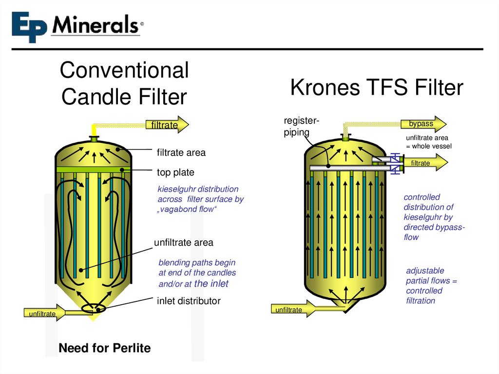
ConventionalCandle Filter
filtrate
Krones TFS Filter
registerpiping
filtrate area
bypass
unfiltrate area
= whole vessel
filtrate
top plate
kieselguhr distribution
across filter surface by
„vagabond flow“
controlled
distribution of
kieselguhr by
directed bypassflow
unfiltrate area
blending paths begin
at end of the candles
and/or at the inlet
adjustable
partial flows =
controlled
filtration
inlet distributor
unfiltrate
unfiltrate
Need for Perlite
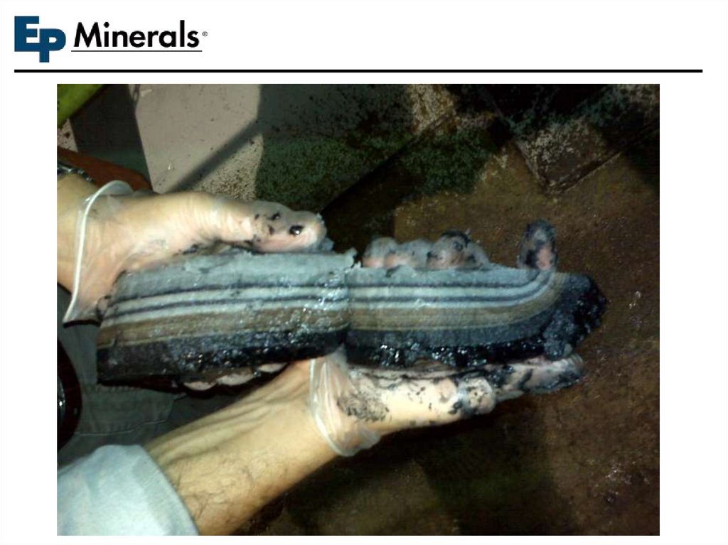
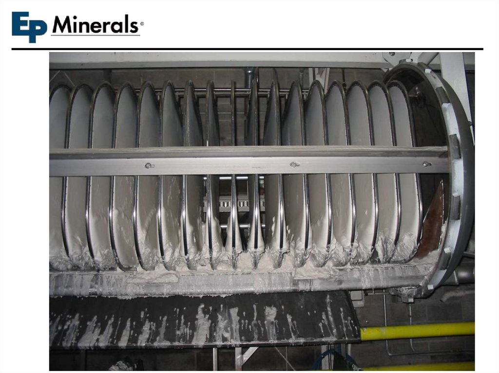
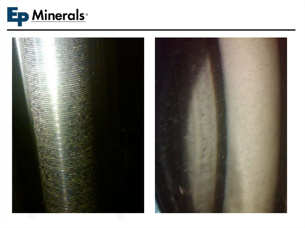
98. Precoat Tests with Filtrate Beer and Pushout with CO2
2400 mm (8 ft) long filter elementsAfter precoat with filtrate beer
First precoat with
coarse grade very
evident. Second
precoat and cake
formation very
even.
99.
100.
101.
BSI & SHELF LIFEConfidential and proprietary
information © 2007 EPM, LLC
102. Factors Affecting Iron Levels in Beer
Initial BSI Level of Filter Aid
Amount of filter media used per filtered barrel
Iron Pick-up in Beer =
Initial BSI level x (DE Usage)
Weight of Beer per Hl
OTHER FACTORS THAT CAN INFLUENCE BSI
• Contact Time
• Temperature
• PH
Confidential and proprietary information © 2007 EPM, LLC
We can impact
these!