


")
")
")
 p")
 p")


")
")
")
")


 Промышленность
Похожие презентации:


Ewafe Power System
1.
eWAFE Power SystemTraining
2. Welcome
This is the eWAFE Power System Training Module.This module covers:
– Power System Structure
– Power Distribution Interface Module (PDIM)
– Power Panel
– Electrical Fault Protection System (EFPS)
– MSCT Power Panel
– LCM Power Panel
– MDT/XPT Power Panel
– DC DeltaV Power Panel
– XTRA-A Power Panel
– Troubleshooting
August 2011
3. Power Structure
The eWAFE power system consists of the PDIM (PowerDistribution Interface Module), the UPM (Universal Power
Module), and the Front End Power Panel.
August 2011
4. Power Structure – FEPC
The Front-end Primary Controllersoftware (FEPC) manages the
power delivery of the eWAFE.
The FEPC power panel functions
include:
– Controls voltage applied to the
power paths
– Shows measured current and
surface and downhole voltages
– Allows viewing and clearing EFPS
fault conditions
– Allows power shutdown
– Provides basic telemetry
indicators:
• Telemetry up/down
• Telemetry CRC
August 2011
5. Power Structure – PDIM
The PDIM primarily manages interconnects betweenthe Universal Power Modules Drawer (UPDM) and the
logging cable. PDIM features include:
– Head voltage stabilization for DC power
– Electrical Fault Protection System
– Laterolog Current Module (LCM) to provide 35 Hz power
for Laterolog tools
– SP and CCL measurements
– Supports Manual Close operations
– Cable Trim
August 2011
6. Power Structure – UPM
• UPM can provide up to 1100 Vrms, 1.64 Arms ACpower.
– The programmable frequency range for this power is
between 30 to 120 Hz.
– The phase is also programmable.
• It can provide up to 2200 V phase to phase (+/- 1100
V to ground), 1.64 ADC power.
• It can provide up to 500 Vrms, 3.28 Arms Ultra Low
Frequency (UELF) power.
– The programmable frequency range for this power is
between 0.2 to 10 Hz.
August 2011
7. PDIM Front Panel Status Lights
• Power LED indicates whether the module isON/OFF and is lit when the module has power.
• Fault LED indicates a problem with the module and
becomes red when the module fails one or more
diagnostic power-up tests. If Safe Mode is bypassed
to Running Mode, the LED becomes yellow.
• Active PDIM LED shows that the module is in an
active operating mode as opposed to a backup
mode.
• Net LED blinks continuously to indicate that the
module is connected and communicating with the
network.
August 2011
8. PDIM Hardware Reset
• The front panel provides access to hardwarereset through the Reset hole. A reset is
triggered by inserting a paper clip or other
similar pin into the Reset hole.
• It is also possible to use software reboot
from the PDIM web page.
August 2011
9. Manual Close Switches
• PMS, Power Mode Switch, is used in manual close operationto select Standard or DTPS mode of operation.
• PCS, Power Control Switch, is used in manual close operation
to confirm operation and increase/decrease AC AUX voltage
for manual close mode.
August 2011
10. PDIM Front Panel Display
The PDIM features a front panel display which displays messages relatingto the status of the module. Some of the displayed messages are:
– SAFE MODE – module is in safe mode due to some power up tests failing.
– RUNNING – module is in RUN mode and is ready for use.
– RUNNING Temp=32dC PWR ON – module is delivering power with at least
one voltage above 20 V.
– NO PC COMM, USE PMS FOR MANUAL CLOSE – Emulator is not open
or physical communication to the MCMP has been lost. Manual Close can be
performed at this time.
– PC ONLINE PMS OFF TO EXIT – PC is connected but PMS (Power
Mode Switch) is not in the OFF position. User intervention is required.
There are additional messages that are reported during self tests and
manual close. The purpose of these messages is to provide the user with
information and/or to prompt user’s intervention.
August 2011
11. PDIM Measurements Web Page
The PDIM Measurements web page provides the values of the various voltageand current measurements made by the PDIM. These include the different
UPM hardware configuration voltages and currents, the wire voltages and
currents, on board supply voltages (+/-12V, 5V, 3.3/1.5V), etc.
August 2011
12. PDIM Measurements (1)
The PDIM Measurements page is NOT updated in real-time.Click the Refresh button to get the latest measurements.
August 2011
13. PDIM Measurements (2)
Click on the video below for a demonstration.August 2011
14. PDIM Power Up (1)
Before powering up the PDIM, ensure that theCSS is in the instrumentation position.
• If the CSS is in any other position, then while performing
the self tests, the PDIM will wait for 3 minutes for the
user to put the CSS in the correct position.
• During these three minutes, the PDIM front panel
display shows the following message:
Also, the Status web page will display a message every 20
seconds giving the time left to change to a legal position,
e.g., ‘CSS in bad position – Timeout in 180 sec’.
August 2011
15. PDIM Power Up (2) p
• On power up, all the front panel LEDs are initially lit. Then the RED front-panelLED begins blinking. This indicates that the power up self-tests are running.
This LED will continue blinking while the power up self-test are running.
August 2011
16. PDIM Power Up (3) p
• If all the self tests are successful, then the module will go inthe Running mode and the Fault LED will go off. Also, the
display will show the relevant message.
• If any of the self tests fail, then the module will go in the “Safe
Mode” and the Fault LED will stay red. If the user bypasses
Safe mode from the PDIM web pages, the Fault LED will turn
yellow.
August 2011
17. Manual Close Operation
PDIM supports manual close protocol with a UPM and interaction withfront panel interface (display and push buttons). This mode of operation
is used to close calipers and pull out of hole (POOH) in case of system
failure with a tool stuck in the hole with open calipers. The UPM has to
be installed in slot #2 to enable AC Aux for manual close for calipers.
August 2011
18. Manual Close Operation Sequence
1.When there is no communication with the WAFE Emulator, the following
message displays on the front panel:
NO PC COMM, PICK PWR MODE FOR MAN CLOSE.
2.
Select the Power mode (STD or DTPS) using the Power Mode Switch (PMS) to
start the manual close process. Follow the instructions of the displayed
messages:
SET PMS OFF FOR MAN CLOSE
CONFIRM PWR MODE FOR MAN CLOSE
HOLD PCS DOWN TO BEGIN MAN CLOSE
PCS CONTROLS PWR
Below this message, the measured current, applied voltage, and measured voltage
display.
3.
Press the Power Control Switch (PCS) UP or DOWN to increase or decrease the
applied voltage and to get the desired current.
August 2011
19. Power Panel
The Power Panel displays automatically when OP/MaxWell request powerindicating that power is enabled; however, no power is applied. This is
equivalent to WAFE when the WFDD prompts the user to hold the function key
and turn the variac. If more than one type of power is requested, each panel
will be stacked to the right of the main panel.
The type of power requested is
determined by the OP/MaxWell
tool software and is shown in
the top-left corner of the panel.
Each type of power has its
own control and display.
August 2011
20. Power Panel – eWAFE Link
When the Power Panel is displayed, the eWAFE Link LED is always solid blueto indicate that there is connection with the eWAFE Emulator (OP) or eWAFE
Server (MaxWell).
August 2011
21. Power Panel – Telemetry CRD
The Telemetry CRC LED blinks when there is excessive noise onthe telemetry link.
August 2011
22. Power Panel – Emergency Shutdown
To perform an emergency shutdown, click the EMERGENCY SHUTDOWNbutton to immediately stops sending power to the downhole tools. This
button provides an option to quickly stop the power without having to use
the slider in case of a safety concern.
August 2011
23. Power Panel – Trend Graph
Clicking on the black bar expands the power panel to show a trendgraph as shown.
August 2011
24. Power Panel – Power Paths
The look and feel of most power paths, such as AC Main and AC Aux is similar withminor differences. For AC Main, there are three bars next to the graph: surface
voltage, downhole voltage, and current.
August 2011
25. Power Panel – AC Aux Power Path
For AC Aux, there are two bars next to the graph: surface voltage and current. Thissetting is typical for most power paths.
August 2011
26. Power Panel – Emex Power Path
The voltage and current controls on Emex are disabled, indicating that Emex iscontrolled by the tool software and cannot be changed manually.
August 2011
27. Power Panel – Surface Voltage
The surface voltage bar has a slider to control the voltage that will be sentfrom eWAFE to the tools.
August 2011
28. Power Panel – Power Up
Powering up with the eWAFE Power Panel is a two-hand operation. Holdthe Shift key on the keyboard while dragging the slider with the mouse.
Click on the picture for a video demonstration.
August 2011
29. Power Panel - Power Up Indicators
The head voltage is shown on the D-hole voltage bar in gray color, indicating estimated
downhole head voltage based on cable trim. This is also shown as light blue color curve in
the trend graph.
Telemetry is trying to establish communication, as indicated by the Telemetry Up LED
blinking in yellow. Once the tool string is powered up successfully and the telemetry link
is established, the Telemetry Up LED will turn solid blue.
The downhole voltage bar will also turn blue indicating downhole voltage is coming from
telemetry instead of estimation. The corresponding downhole voltage curve in the trend
graph will also turn to a darker blue
Click on the video for a demonstration.
August 2011
30. Power Panel – Current Bar
The current bar always shows current readback from the eWAFEsystem (UPM to be specific). There is no current readback from the
telemetry cartridge.
August 2011
31. Power Panel – Change Display Scale
There are two methods to change the display scale:1. The first method is to right-click on each bar graph to display
a drop-down menu listing available scales.
August 2011
32. Power Panel – Change Display Scale
The second method to change the scale for all the displays at the same time isby clicking the Preferences check box. The Preferences panel shows three
options to set the scales: Low Limits, Medium Limits, and High Limits.
Deselect the Preferences check box to close the Preference pane.
August 2011
33. Power Panel - Incremental Voltage Changes
In order to make incremental changes to the voltage, click the- or + button while holding the Shift key to decrease or
increase the voltage.
August 2011
34.
Power Panel – Yellow Sticky MarkerThe sticky yellow marker placed behind the voltage slider marks
the last power up voltage for telemetry cartridge. The marker is
set when telemetry link is established. The next time the tool is
powered up, slide the slider to the yellow marker. The marker is
reset every time a telemetry link is established and every time
Emulator/eWAFE Server is restarted.
August 2011
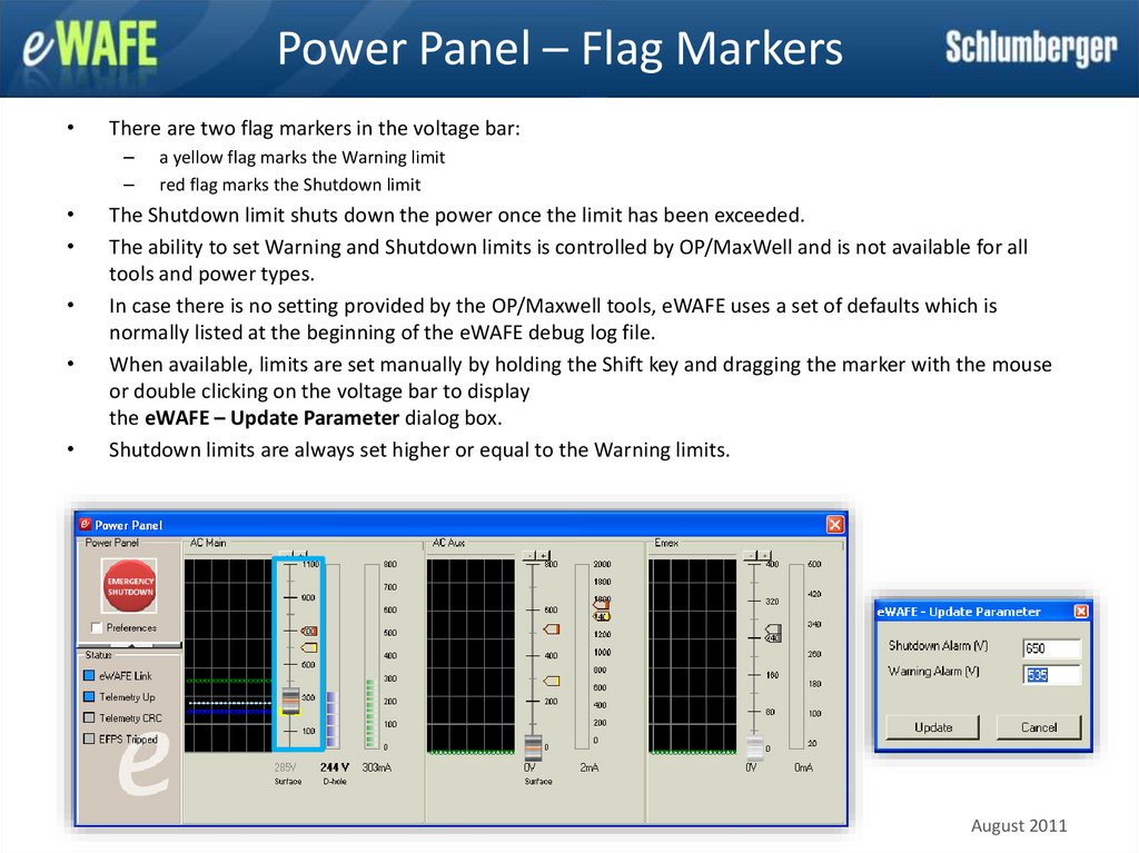
35.
Power Panel – Flag MarkersThere are two flag markers in the voltage bar:
–
–
a yellow flag marks the Warning limit
red flag marks the Shutdown limit
The Shutdown limit shuts down the power once the limit has been exceeded.
The ability to set Warning and Shutdown limits is controlled by OP/MaxWell and is not available for all
tools and power types.
In case there is no setting provided by the OP/Maxwell tools, eWAFE uses a set of defaults which is
normally listed at the beginning of the eWAFE debug log file.
When available, limits are set manually by holding the Shift key and dragging the marker with the mouse
or double clicking on the voltage bar to display
the eWAFE – Update Parameter dialog box.
Shutdown limits are always set higher or equal to the Warning limits.
August 2011
36.
Power Panel – Flag Markers (2)To change the current limit, double-click the Current scale in the AC Aux power
type area to display the eWAFE - Update Parameter dialog box.
Change the Shutdown Alarm and Warning Alarm as shown previously. The Current
Limit prevents the current from going beyond the specified value. This is only
applicable for tools that operate in current limiting mode such as Perfo. The
current limit marker will be displayed for power paths that can be applied in
current limiting mode.
August 2011
37.
Power Panel – MinimizeTo conserve screen space, the Power Panel can be minimized by clicking the up
arrow button, which collapses the Power Panel to a small display of the Downhole
Voltage and Current.
The Power Panel window floats on top of other windows to ensure that it is visible
at all times.
Collapsed Power Panel
To expand again, click the down arrow.
August 2011
38. Electrical Fault Protection System
• The EFPS Manager is an interface tomanage eWAFE's Electrical Fault
Protection System (EFPS) .
• When EFPS trips, the EFPS Tripped
LED will turn red and the EFPS
Manager displays automatically.
August 2011
39. EFPS – General Electric Fault Protection
August 201140. EFPS – General Electric Fault Protection
August 201141. EFPS – General Electric Fault Protection
August 201142. EFPS – Power Path Electric Fault Protection
August 201143. EFPS – Power Path Electric Fault Protection
August 201144. EFPS – Power Path Electric Fault Protection
August 201145. EFPS – Power Path Electric Fault Protection
August 201146. EFPS – Power Path Electric Fault Protection
August 201147. EFPS – Power Path Electric Fault Protection
August 201148. EFPS – Power Path Electric Fault Protection
DC MAIN Special Over Current FaultAugust 2011
49. EFPS – Power Path Electric Fault Protection
August 201150. EFPS – Power Path Electric Fault Protection
August 201151. EFPS – Power Path Electric Fault Protection
August 201152. EFPS – Power Path Electric Fault Protection
August 201153. EFPS – Power Path Electric Fault Protection
August 201154. MSCT Power Panel (1)
• Three different types of MSCT power are controlled through aspecialized power panel. They are MSCT Cartridge, MSCT
Hydraulic, and MSCT Coring.
• At the bottom of each MSCT power path, there is a set of
buttons that allows setting the voltages quickly without dragging
the slider.
August 2011
55. MSCT Power Panel (2)
• The red arrow markers on the Voltage bar graphs mark the preset voltage,which is by default set by OP/MaxWell. The preset voltages
can be set manually by dragging the marker while holding the Shift key.
• The Mark button located at the bottom of the panel is used to set the preset
voltage to the current position of the slider.
• To set the voltage as marked by the red arrow, click the Goto button.
Click Goto
Voltage is set next to red marker
August 2011
56. MSCT Power Panel (3)
• Another feature available in the MSCT power panel is the abilityto quickly zero the voltage by clicking the Zero button.
Click Zero
Voltage is now zero
August 2011
57. MSCT Power Panel (4)
The MSCT Coring power panel has an additional check box labeledPulse. When checked, small current variation indicator (represented
by red vertical bars) is added on top of the current curve in the graph
panel to emphasize the pulse measure as shown next. Click the Pulse
check box and apply voltage.
Click on the picture below for a video demonstration.
August 2011
58. LCM Power Panel
The LCM 35 Hz Current LED is lit to indicate that 35 Hz current is generated.August 2011
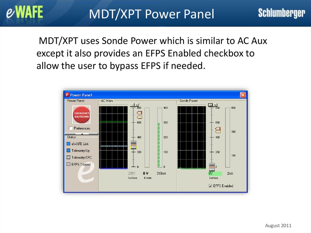
59.
MDT/XPT Power PanelMDT/XPT uses Sonde Power which is similar to AC Aux
except it also provides an EFPS Enabled checkbox to
allow the user to bypass EFPS if needed.
August 2011
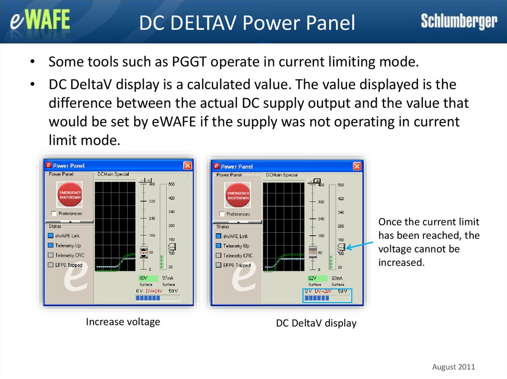
60.
DC DELTAV Power Panel• Some tools such as PGGT operate in current limiting mode.
• DC DeltaV display is a calculated value. The value displayed is the
difference between the actual DC supply output and the value that
would be set by eWAFE if the supply was not operating in current
limit mode.
Once the current limit
has been reached, the
voltage cannot be
increased.
Increase voltage
DC DeltaV display
August 2011
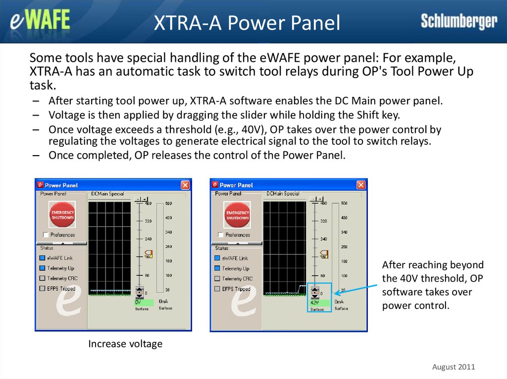
61.
XTRA-A Power PanelSome tools have special handling of the eWAFE power panel: For example,
XTRA-A has an automatic task to switch tool relays during OP's Tool Power Up
task.
– After starting tool power up, XTRA-A software enables the DC Main power panel.
– Voltage is then applied by dragging the slider while holding the Shift key.
– Once voltage exceeds a threshold (e.g., 40V), OP takes over the power control by
regulating the voltages to generate electrical signal to the tool to switch relays.
– Once completed, OP releases the control of the Power Panel.
After reaching beyond
the 40V threshold, OP
software takes over
power control.
Increase voltage
August 2011
62. Troubleshooting
August 201163. Troubleshooting
August 201164. Troubleshooting
• UPM not able to deliver required voltage1. Run the SUIT test.
2. If SUIT test fails (due to voltages not within threshold),
then conclude that the UPM is faulty.
• PDIM reboot
1. In some instances, the PDIM reboots due to faulty UPM
that generates high voltage spikes.
2. Run the SUIT test to check for this failure and identify the
faulty UPM.
August 2011