


 Промышленность
Похожие презентации:


Application Considerations 4016 Series Diesel
1. Application Considerations
4016 Series DieselProprietary Information of Perkins Engines Company Limited 2006 - All Rights Reserved
Perkins Confidential ‘Green’
2. Application Considerations
Please Note :This Product Training information is distributed for informational
purposes only
It is to provide the user with sound general information for
installing an engine/generating set within an engine
room/canopy facility
It is for guidance and assistance in the application of an engine
with recommendations for correct and safe procedure
It may not be construed as creating or becoming part of any
Perkins Engines contractual or warranty obligation
Proprietary Information of Perkins Engines Company Limited 2006 - All Rights Reserved
Perkins Confidential ‘Green’
3. Installation Considerations
Proprietary Information of Perkins Engines Company Limited 2006 - All Rights ReservedPerkins Confidential ‘Green’
4. Installation Considerations
Proprietary Information of Perkins Engines Company Limited 2006 - All Rights ReservedPerkins Confidential ‘Green’
5. Installation Considerations
Proprietary Information of Perkins Engines Company Limited 2006 - All Rights ReservedPerkins Confidential ‘Green’
6. Installation Considerations
Proprietary Information of Perkins Engines Company Limited 2006 - All Rights ReservedPerkins Confidential ‘Green’
7. Installation Considerations
Torsional CompatibilityFlywheel Housing and Flywheel
Engine Room Foundations
Mounting
Engine Room Layout
Ventilation
Cooling System
Cold Start
Exhaust System
Fuel System
Crankcase Ventilation
Electrical Systems
Air Induction System
Noise
Governor
Multiple Gensets Installation
Proprietary Information of Perkins Engines Company Limited 2006 - All Rights Reserved
Perkins Confidential ‘Green’
8. Installation Considerations
Torsional CompatibilityProprietary Information of Perkins Engines Company Limited 2006 - All Rights Reserved
Perkins Confidential ‘Green’
9. Torsional Vibration
Torsional Vibration Analysis (TVA)ISO 8528 places the onus of ensuring torsional compatibility
on the generating set manufacturer
Information required = Inertia’s of rotating components,
shafts, pulleys, etc., and dimensions and stiffness of shafts
Perkins can offer TVA and this should be requested on Order
Control Document (OCD) as it is a charge-able option
Perkins provide the full Mass Elastics of the 4016 for OEM’s
wishing to conduct their own TVA
Proprietary Information of Perkins Engines Company Limited 2006 - All Rights Reserved
Perkins Confidential ‘Green’
10. Torsional Vibration
Proprietary Information of Perkins Engines Company Limited 2006 - All Rights ReservedPerkins Confidential ‘Green’
11. Torsional Vibration
Proprietary Information of Perkins Engines Company Limited 2006 - All Rights ReservedPerkins Confidential ‘Green’
12. Torsional Vibration
Proprietary Information of Perkins Engines Company Limited 2006 - All Rights ReservedPerkins Confidential ‘Green’
13. Torsional Vibration
Proprietary Information of Perkins Engines Company Limited 2006 - All Rights ReservedPerkins Confidential ‘Green’
14. Torsional Vibration
Proprietary Information of Perkins Engines Company Limited 2006 - All Rights ReservedPerkins Confidential ‘Green’
15. Torsional Vibration
TV Analysis ResultsStress Limit for the crankshaft
Damper Heat Load = 110º C for Standby ratings
Vibrating amplitude at crankshaft nose
Limit = 1º at full load rated speed
Vibratory Torque (to check coupling bolts)
Proprietary Information of Perkins Engines Company Limited 2006 - All Rights Reserved
Perkins Confidential ‘Green’
16. TV Dampers
HeavyAnnular
Mass
Light
Metal
Casing
Cover
Viscous Dampers are used on fixed
speed applications like gen-sets. As
a consequence they are used on all
the Stafford range of engines.
At low vibrations the heavy annular
mass moves with the casing but at
large vibration amplitudes the
damper mass slips in relation to the
casing. The energy absorbed is
dissipated as heat.
Gap Filled with
Silicone Fluid
Proprietary Information of Perkins Engines Company Limited 2006 - All Rights Reserved
Perkins Confidential ‘Green’
17. Applications Considerations
Flywheel Housing and FlywheelProprietary Information of Perkins Engines Company Limited 2006 - All Rights Reserved
Perkins Confidential ‘Green’
18. Flywheel Housing and Flywheel
Flywheel Housing and Flywheel Size4016 Supplied with :
SAE J617 Size 00 - Flywheel Housing
SAE J620 Size 18 - Flywheel
Proprietary Information of Perkins Engines Company Limited 2006 - All Rights Reserved
Perkins Confidential ‘Green’
19. Applications Considerations
Engine Room FoundationsProprietary Information of Perkins Engines Company Limited 2006 - All Rights Reserved
Perkins Confidential ‘Green’
20. Engine Room Foundations
Type of FoundationThe engine floor/foundation where the underbase/bearers are
fixed is of great importance as it must:
Support the static weight of the units and withstand any
stresses or vibrations when the engine is running,
Be sufficiently rigid and stable so that there will be no
distortion which would affect the alignment of the engine and
driven unit
Absorb vibrations originating from the running units and
prevent them being transmitted to the surrounding floor and
walls etc.
Proprietary Information of Perkins Engines Company Limited 2006 - All Rights Reserved
Perkins Confidential ‘Green’
21. Engine Room Foundations
Subsoil - SiteThe site subsoil must have a bearing strength capable of
supporting the weight of the complete set plus the concrete
foundation on which it will stand
If the bearing strength of the subsoil is in doubt advice should
be taken from a qualified civil engineer to enable the type and
size of concrete foundations to be determined
Proprietary Information of Perkins Engines Company Limited 2006 - All Rights Reserved
Perkins Confidential ‘Green’
22. Engine Room Foundations
Fixed Concrete BlockThe fixed concrete block is a proven method
The recommended plan size of the fixed concrete block is to
allow between 300/450 mm surround on all sides of the set
The surface of the block is usually proud of the normal floor line
by 'h‘ between 100/230 mm and forms a plinth
Each genset must have its own individual plinth
Proprietary Information of Perkins Engines Company Limited 2006 - All Rights Reserved
Perkins Confidential ‘Green’
23. Engine Room Foundations
Fixed Concrete BlockThe depth of the concrete block is calculated as follows:
D=
W
dxBxL
D = Depth of concrete block in metre
W = Total weight of generating set in kg
d = Density of concrete in kg/m3
NOTE: 2403.8 kg/m3 if accurate figures are not known.
B = Breadth of concrete block in metre
L = Length of concrete block in metre
Proprietary Information of Perkins Engines Company Limited 2006 - All Rights Reserved
Perkins Confidential ‘Green’
24. Engine Room Foundations
Fixed Concrete BlockAfter determining the depth of concrete required for the
weight and stability of the running set, the subsoil has to be
checked to see if it will carry the total weight (set plus
concrete block) and withstand the forces involved
Proprietary Information of Perkins Engines Company Limited 2006 - All Rights Reserved
Perkins Confidential ‘Green’
25. Installation Considerations
Engine MountingProprietary Information of Perkins Engines Company Limited 2006 - All Rights Reserved
Perkins Confidential ‘Green’
26. Mounting Systems
Purpose Of Mounting SystemsTo secure the engine into the installation
Provide adequate support in order to avoid mechanical failure
To allow adequate movement to give engine freedom to move
with out of balance forces
Provide adequate damping and suppression of engine
vibration
Proprietary Information of Perkins Engines Company Limited 2006 - All Rights Reserved
Perkins Confidential ‘Green’
27. Mounting Systems
Engine MountingsThe type of mountings depend upon the type of installation in
which the engine is to be used and the final drive arrangement
The engine can be fitted with either solid or flexible mountings,
depending on the type of foundation or application
If the engine is solidly or flexibly mounted, the exhaust,
radiator and fuel pipe connections must also be flexible
Proprietary Information of Perkins Engines Company Limited 2006 - All Rights Reserved
Perkins Confidential ‘Green’
28. Mounting System
Types Of Mounting SystemsFlexible Mounting Systems
Solid Mounting System
Proprietary Information of Perkins Engines Company Limited 2006 - All Rights Reserved
Perkins Confidential ‘Green’
29. Mounting Systems
Types Of Mounting Systems - FlexibleFlexible mounting enable the supporting baseframe to be
isolated from genset
Vibration, the forces generated by the genset being
counteracted by allowing the genset itself to move bodily on
anti vibration mounts between the genset and baseframe
Flexible mounting is not the preferred method for 4000
Series Vee Form engines, and AV mount recommendations
must be followed
Flexible mounts can be 6-point or 8-point fixes
Proprietary Information of Perkins Engines Company Limited 2006 - All Rights Reserved
Perkins Confidential ‘Green’
30. Mounting Systems
Proprietary Information of Perkins Engines Company Limited 2006 - All Rights ReservedPerkins Confidential ‘Green’
31. Mounting Systems
Proprietary Information of Perkins Engines Company Limited 2006 - All Rights ReservedPerkins Confidential ‘Green’
32. Mounting Systems
Location of MountsWith flexible mounting the location of the mounts are
predetermined by the mounting feet on the engine
The location of the rear mounts (under the alternator) should
be calculated to ensure that the bending moment at the joint
face between the crankcase and flywheel housing does not
exceed 1356Nm
A calculation is available from Perkins to calculate the
bending moments for 6-point fixes, 8-point fixes do not
require bending moments to be calculated
Proprietary Information of Perkins Engines Company Limited 2006 - All Rights Reserved
Perkins Confidential ‘Green’
33. Mounting Systems
Proprietary Information of Perkins Engines Company Limited 2006 - All Rights ReservedPerkins Confidential ‘Green’
34. Mounting Systems
Types Of Mounting Systems - SolidSolid mounting are used where the movements of a flexiblymounted genset is not acceptable
The genset itself is an integral part of the genset baseframe
structure
Allows the genset and baseframe to move bodily on anti
vibration mounts between the frame and floor
Proprietary Information of Perkins Engines Company Limited 2006 - All Rights Reserved
Perkins Confidential ‘Green’
35. Mounting Systems
Proprietary Information of Perkins Engines Company Limited 2006 - All Rights ReservedPerkins Confidential ‘Green’
36. Mounting Systems
Locations Of MountsWith solid mounting the anti vibration mounts should be
symmetrically arranged about the combined centre of gravity
of the bolted equipment
Proprietary Information of Perkins Engines Company Limited 2006 - All Rights Reserved
Perkins Confidential ‘Green’
37. Mounting Systems
Proprietary Information of Perkins Engines Company Limited 2006 - All Rights ReservedPerkins Confidential ‘Green’
38. Mounting Systems
General ConsiderationsNo restraints from exhaust pipes, hoses, linkages, etc
Are the mounts fitted correctly and used as they were
designed to be used
Was the mount manufacturer involved in the design of the
mounting system
Proprietary Information of Perkins Engines Company Limited 2006 - All Rights Reserved
Perkins Confidential ‘Green’
39. Mounting Systems
Types Of AV MountsRubber without adjustment - First grade natural rubber to
metal bonded rectangular elements inclined to achieve
maximum load and deflection of compression and shear
loading
Steel Spring and rubber without adjustment - helical steel
spring, inclined rubber springs of first grade natural rubber to
metal bonded elements
Not Solid Rubber Pads without casings
Proprietary Information of Perkins Engines Company Limited 2006 - All Rights Reserved
Perkins Confidential ‘Green’
40. Applications Considerations
Engine Room layoutProprietary Information of Perkins Engines Company Limited 2006 - All Rights Reserved
Perkins Confidential ‘Green’
41. Engine Room Layout
Access for Routine ServicingInstallation and removal of various components :
Cylinder heads
Coolant pump
Oil sump
Timing case
Starter and alternator
Flexible mountings
Proprietary Information of Perkins Engines Company Limited 2006 - All Rights Reserved
Perkins Confidential ‘Green’
42. Engine Room Layout
Access for Routine ServicingMaintenance, inspection and replacement of parts :
Lubricating oil filter
Air cleaner
Fuel filter
Lubricating oil filler
Crankcase breather
Dipstick
Radiator filler cap and access for filling
Proprietary Information of Perkins Engines Company Limited 2006 - All Rights Reserved
Perkins Confidential ‘Green’
43. Engine Room Layout
Installation Guide linesAvoid plastic and other unsuitable material for fuel piping and
connections, which can corrode or chafe and leak fuel
Keep fuel lines away from hot exhaust pipes
Insulate exhaust systems, using heat shields or lagging
NOTE : Dry engine exhaust manifolds must not be lagged
Install a fire extinguishing system in the engine room
Make provision for draining the oil sump and fit drip tray
underneath
Check entrance is large enough to allow engine/alternator to be
removed
Provide adequate lighting and power points
Lifting beam in roof for maintenance
Provision for draining engine cooling system
All rotating shafts are adequately guarded for safety purposes
Proprietary Information of Perkins Engines Company Limited 2006 - All Rights Reserved
Perkins Confidential ‘Green’
44. Engine Room Layout
Typical Engine Room LayoutHot air from the radiator ducted outside the engine room and
not allowed to re-circulate
Exhaust system to be support from roof and flexible bellows
fitted used to isolate engine and exhaust system
Hot air outlet ducting, fuel connections and electrical
connections must be flexible type to the engine and
alternator
The daily fuel tank is supplied from a bulk tank housed
remotely from the engine room
The starter batteries are to be kept fully charged during none
running periods by a static charger, which can be
incorporated in the control panel
Proprietary Information of Perkins Engines Company Limited 2006 - All Rights Reserved
Perkins Confidential ‘Green’
45. Engine Room Layout
Proprietary Information of Perkins Engines Company Limited 2006 - All Rights ReservedPerkins Confidential ‘Green’
46. Installation Considerations
VentilationProprietary Information of Perkins Engines Company Limited 2006 - All Rights Reserved
Perkins Confidential ‘Green’
47. Ventilation
VentilationBasic principal is to extract hot air from the room and induce air
at the outside ambient temperature with minimum recirculation
The object is to get cool air in at the lowest point, push it
through the radiator matrix and out of the building
Radiators must be ducted to the opening
It is unsatisfactory to position the set so that the radiator is
adjacent to the opening in the wall
Proprietary Information of Perkins Engines Company Limited 2006 - All Rights Reserved
Perkins Confidential ‘Green’
48. Ventilation
Proprietary Information of Perkins Engines Company Limited 2006 - All Rights ReservedPerkins Confidential ‘Green’
49. Ventilation
Proprietary Information of Perkins Engines Company Limited 2006 - All Rights ReservedPerkins Confidential ‘Green’
50. Ventilation
Proprietary Information of Perkins Engines Company Limited 2006 - All Rights ReservedPerkins Confidential ‘Green’
51. Ventilation
Outlet/Inlet SizesThe outlet opening should have a free flow area approximately
25% larger than the radiator matrix
Radiator ducting must have a flexible section to isolate
vibration and movement. This is particularly important when
the set is mounted on AVM’s
The inlet should also have a free flow area approximately 25%
larger than the radiator matrix
Proprietary Information of Perkins Engines Company Limited 2006 - All Rights Reserved
Perkins Confidential ‘Green’
52. Ventilation
Proprietary Information of Perkins Engines Company Limited 2006 - All Rights ReservedPerkins Confidential ‘Green’
53.
VentilationExtract from Institute of
Heating & Ventilation
Engineers Guide & Wood
Practical Guide to Fan
Engineering
Proprietary Information of Perkins Engines Company Limited 2006 - All Rights Reserved
Perkins Confidential ‘Green’
54.
VentilationExtract from Institute of
Heating & Ventilation
Engineers Guide 1965
Proprietary Information of Perkins Engines Company Limited 2006 - All Rights Reserved
Perkins Confidential ‘Green’
55. Ventilation
Duct ResistanceRadiator duct allowance must not be exceeded.
Exceeding the duct allowance can cause the fan to run in a
stalled condition.
Running a fan in stall will lead to fan failure.
Airflow must be measured at the radiator outlet matrix to
determine actual flow.
Measured flow must be at least the design minimum flow.
If minimum design airflow is achieved with minimal margin
at core face it is unlikely that sufficient airflow will be
available once front attenuation and louvers are replaced.
Proprietary Information of Perkins Engines Company Limited 2006 - All Rights Reserved
Perkins Confidential ‘Green’
56.
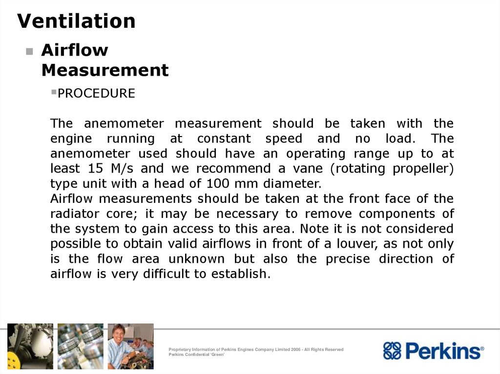
VentilationAirflow
Measurement
PROCEDURE
The anemometer measurement should be taken with the
engine running at constant speed and no load. The
anemometer used should have an operating range up to at
least 15 M/s and we recommend a vane (rotating propeller)
type unit with a head of 100 mm diameter.
Airflow measurements should be taken at the front face of the
radiator core; it may be necessary to remove components of
the system to gain access to this area. Note it is not considered
possible to obtain valid airflows in front of a louver, as not only
is the flow area unknown but also the precise direction of
airflow is very difficult to establish.
Proprietary Information of Perkins Engines Company Limited 2006 - All Rights Reserved
Perkins Confidential ‘Green’
57. Ventilation
Continuous TraverseCarry out a moving traverse over the
radiator face (averaging anemometer)
To do this, position the anemometer at one
corner of the radiator, hold the anemometer
head about 80~100 mm away from and
square with the radiator face. Start
recording/logging
and
traverse
the
anemometer across the whole of the
radiator face moving the head continuously
at a steady speed of about 300mm/s. When
the whole of the face has been traversed
stop recording/logging.
Check that reading is OK and accept result.
Repeat the traverse until 3 readings have
been obtained.
Proprietary Information of Perkins Engines Company Limited 2006 - All Rights Reserved
Perkins Confidential ‘Green’
58. Ventilation
Spot MeasurementsSpot measurements (single reading
anemometer)
This method assumes an anemometer capable of
taking single readings, or logging single readings is
used.
The radiator face should be divided into a grid of
squares approximately 200 x 200 mm. The squares
can be marked onto the face of the radiator using
chalk, a paint marker pen or similar to give
guidance for measurement locations.
To do this, position the anemometer at one corner
of the radiator, hold the anemometer head about
80~100 mm away from and square with the
radiator face. Recording/log the first square and
then
move
to
the
next,
repeating
the
measurement. Repeat this for the whole of the
radiator face. When the whole of the face has been
measured stop recording/logging.
Check that reading is OK and accept result.
Repeat the measurements until 3 readings have
been obtained.
Proprietary Information of Perkins Engines Company Limited 2006 - All Rights Reserved
Perkins Confidential ‘Green’
59.
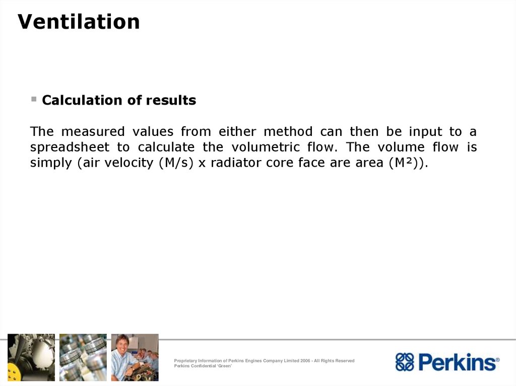
VentilationCalculation of results
The measured values from either method can then be input to a
spreadsheet to calculate the volumetric flow. The volume flow is
simply (air velocity (M/s) x radiator core face are area (M²)).
Proprietary Information of Perkins Engines Company Limited 2006 - All Rights Reserved
Perkins Confidential ‘Green’
60. Ventilation
Ducting Against Prevailing WindRadiator fan is a “pusher” type
If the prevailing wind is blowing into the opening additional
resistance will be put on the fan with a resulting reduction in
cooling air flow
Where possible the opening should be in a wall not affected
by prevailing wind
If the above condition is not possible other methods should
be considered :
Outside ducting with outlet being 90o to cooling air flow
A deflector panel
Proprietary Information of Perkins Engines Company Limited 2006 - All Rights Reserved
Perkins Confidential ‘Green’
61. Ventilation
Proprietary Information of Perkins Engines Company Limited 2006 - All Rights ReservedPerkins Confidential ‘Green’
62. Ventilation
Ventilation – Tropical ConditionsTo cater for tropical conditions common practice is for the
engine room to have open side, consisting of only a roof, with
supporting columns
This type of cover is not suitable for protection against
driven rain, dust or sand
Proprietary Information of Perkins Engines Company Limited 2006 - All Rights Reserved
Perkins Confidential ‘Green’
63. Ventilation
Proprietary Information of Perkins Engines Company Limited 2006 - All Rights ReservedPerkins Confidential ‘Green’
64. Ventilation
Ventilation – Tropical ConditionsWhere multiple gensets are installed in an open sided
building it is imperative that partitions are fitted to prevent
the prevailing wind blowing the radiated heat from one
genset onto the next and so on. Allow access for
maintenance or only enclose the side facing the prevailing
wind.
Proprietary Information of Perkins Engines Company Limited 2006 - All Rights Reserved
Perkins Confidential ‘Green’
65. Ventilation
Proprietary Information of Perkins Engines Company Limited 2006 - All Rights ReservedPerkins Confidential ‘Green’
66. Ventilation
Forced Ventilation – Remote RadiatorExhaust in engine room to be sufficiently lagged so radiated
heat is minimal
Two electric fans : One to push air into the engine room, if the fan is situated
above the genset, a duct should be used to direct the
incoming air to the rear of alternator
One fan to extract air, which should be mounted next to
and above the engine
Recommended engine room is maintained at a maximum
temperature of 38oC.
If ambient temperature exceeds 38oC, then a temperature
rise of no more then 8oC above ambient should be
maintained
Proprietary Information of Perkins Engines Company Limited 2006 - All Rights Reserved
Perkins Confidential ‘Green’
67. Ventilation
Proprietary Information of Perkins Engines Company Limited 2006 - All Rights ReservedPerkins Confidential ‘Green’
68. Ventilation
Forced Ventilation CalculationTo determine the temperature rise in the engine room
requires the airflow to be calculated :Airflow =
Airflow =
TCR =
W=
RT =
TCR_____
W x 0.0167 x RT
m3/min
Total radiated heat (kWth)
Density of air at fan inlet (kg/m3)
Rise in temperature (oC)
Total heat dissipated is the heat radiated from the engine,
alternator and any other heat source
Combustion airflow requirement to be added to the above
figure
Proprietary Information of Perkins Engines Company Limited 2006 - All Rights Reserved
Perkins Confidential ‘Green’
69. Ventilation
Engine and (Typical) Alternator Radiant Heat to theEngine Room (kWt) – Standby Ratings
Engine Type
Engine Speed (rpm)
Alternator Speed (rpm)
1500
1800
1500
1800
4016TAG
125
NA
72.7
NA
4016TAG1A
127
NA
75.8
NA
4016TAG2A
172
NA
82.7
NA
4016TWG2
166
NA
80.6
NA
Proprietary Information of Perkins Engines Company Limited 2006 - All Rights Reserved
Perkins Confidential ‘Green’
70. Installation Considerations
Exhaust SystemProprietary Information of Perkins Engines Company Limited 2006 - All Rights Reserved
Perkins Confidential ‘Green’
71. Exhaust Systems
Exhaust System InstallationKeep weight off the turbocharger and exhaust outlet elbow
by supporting the exhaust system
Provide flexibility between the engine outlet and exhaust
system
Allow for thermal expansion and contraction
Exhaust pipe connections must be leak free
Drainage of exhaust system
A small drain hole should be incorporated in the lowest
part of exhaust
On vertical stacks a flap should be fitted or turned through
90 degrees to give horizontal outlet and so protect from
rain ingress
Proprietary Information of Perkins Engines Company Limited 2006 - All Rights Reserved
Perkins Confidential ‘Green’
72. Exhaust Systems
Do Not :Pipe multiple engine exhausts into a common system – Each
engine must have it’s own separate system and individual
outlet
Use an existing stack that is used for other purposes. Engine
pulsations can upset updraft required by boiler systems
Use existing disused chimneys unless their integrity has been
checked
Do not lag exhaust manifolds or turbochargers, this will lead
to operating deficiencies and failure of parts due to thermal
stress
Proprietary Information of Perkins Engines Company Limited 2006 - All Rights Reserved
Perkins Confidential ‘Green’
73. Exhaust Systems
Proprietary Information of Perkins Engines Company Limited 2006 - All Rights ReservedPerkins Confidential ‘Green’
74. Exhaust Systems
Proprietary Information of Perkins Engines Company Limited 2006 - All Rights ReservedPerkins Confidential ‘Green’
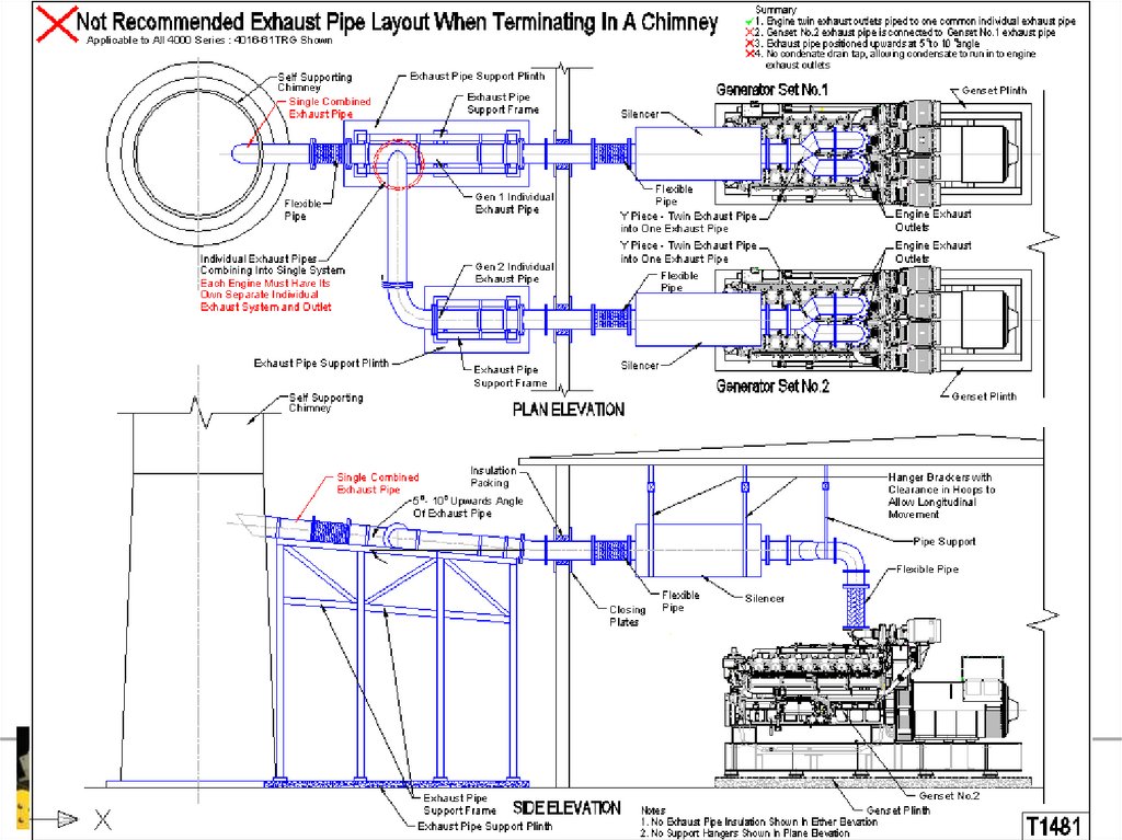
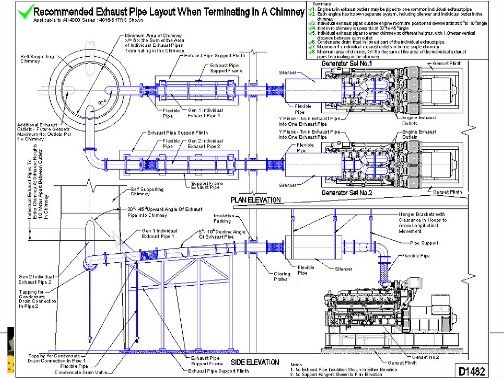
75. Exhaust Systems
Exhaust System Terminating in ChimneyEngine twin exhaust outlets may be piped in to one common
individual exhaust pipe
Engine to have individual outlet in chimney
Individual exhaust pipe outside engine room are positioned
downwards at 5o to 10o angle, to prevent condensate running
back towards the engine exhaust outlet
Inlet to chimney is upwards 30o to 45o
Condensate drain fitted in the lowest part of the individual
exhaust pipe
Proprietary Information of Perkins Engines Company Limited 2006 - All Rights Reserved
Perkins Confidential ‘Green’
76. Exhaust Systems
Exhaust Systems Terminating in Chimney MultipleIndividual exhaust pipes to enter chimney at different
heights, with 1.0meter vertical distance between each outlet
Maximum of 4 x individual exhaust outlets in one single
chimney
Minimum area of chimney >/= 6 x the sum of the area of the
individual exhaust pipes terminating in the chimney
For further details please refer to Product Bulletin A1/12/66
August 2012 and schemes D1481 and D1482
Proprietary Information of Perkins Engines Company Limited 2006 - All Rights Reserved
Perkins Confidential ‘Green’
77.
Proprietary Information of Perkins Engines Company Limited 2006 - All Rights ReservedPerkins Confidential ‘Green’
78.
Proprietary Information of Perkins Engines Company Limited 2006 - All Rights ReservedPerkins Confidential ‘Green’
79. Exhaust Systems
Piping :To prevent build-up of resonant pipe vibrations, long piping
runs should be supported at unequal distances
Proprietary Information of Perkins Engines Company Limited 2006 - All Rights Reserved
Perkins Confidential ‘Green’
80. Exhaust Systems
Exhaust System InstallationThe exhaust system should avoid touching or passing
close to ;
Lub oil and fuel filters, fuel tank and LP/HP fuel systems
Radiator, sump and air cleaner
Engine wiring and sensors
Proprietary Information of Perkins Engines Company Limited 2006 - All Rights Reserved
Perkins Confidential ‘Green’
81. Exhaust Systems
Exhaust System LaggingTo reduce radiated heat from the exhaust pipework within an
engine room, it is recommended the pipework is insulated
with insulating wrappers 25mm to 50mm thickness.
A. Clip-on insulation wrapper
B. Clip-on insulation muff
Do not lag exhaust manifolds or turbochargers, this will lead
to operating deficiencies and failure of parts due to thermal
stress
Proprietary Information of Perkins Engines Company Limited 2006 - All Rights Reserved
Perkins Confidential ‘Green’
82. Exhaust Systems
Back PressureThe exhaust system will produce a certain resistance to the
flow of exhaust gases
The back pressure for the total system must be kept within
the limit of each engine maximum :Engine Type
Maximum Allowable
Exhaust Back Pressure
at 1500rpm (kPa)
Maximum Allowable
Exhaust Back Pressure
at 1800rpm (kPa)
4016TAG/TAG1A
9.35
NA
4016TAG2A / TWG2
6.65
NA
Proprietary Information of Perkins Engines Company Limited 2006 - All Rights Reserved
Perkins Confidential ‘Green’
83. Exhaust Systems
Back Pressure CalculationBack pressure of a proposed exhaust system can be
calculated by using :P=
L x Q2 x 1187 x 109
D5.33
P = Back pressure (mmHg)
Q = Gas flow (kg/s)
L = Total equivalent length * straight pipe (M)
D = Pipe diameter (mm)
Back pressure losses through silencer(s) must be added to the
above to obtain total system losses
Proprietary Information of Perkins Engines Company Limited 2006 - All Rights Reserved
Perkins Confidential ‘Green’
84. Exhaust Systems
Effects of Excessive Exhaust Back PressureToo high a back pressure leads to:
Loss of power: approx. 0.5% decrease for each 3.3kPa
above maximum level
Poor fuel economy: fuel consumption increases by approx.
0.5% for each 3.3kPa above maximum level
High combustion temperature: 2.5% increase in exhaust
gas temperature for each 3.3kPa above maximum level
These conditions produce over-heating and excessive
smoke from the installation, and reduce the lives of the
valve heads and valve seats
Because of the above the 5kPa limit on the 4012-46 Series
must not be exceed, the exhaust pipe internal bore will
have to be increased or pipe run length reduced
Perkins do not produce exhaust back pressure derate
charts
Proprietary Information of Perkins Engines Company Limited 2006 - All Rights Reserved
Perkins Confidential ‘Green’
85. Exhaust Systems
Exhaust Outlet Flange Size4016 Supplied with :
Twin 250mm BS 10 Table ‘D’ Outlet Flanges
Proprietary Information of Perkins Engines Company Limited 2006 - All Rights Reserved
Perkins Confidential ‘Green’
86. Installation Considerations
The Cooling SystemProprietary Information of Perkins Engines Company Limited 2006 - All Rights Reserved
Perkins Confidential ‘Green’
87. Cooling System
Cooling System RequirementsPressure cap setting 70kPa is maintained in the system
98oC top tank
Ambient clearance
50% Glycol
50oC Tropical
50% Glycol
35oC Temperate
Tested at 110% operating load
Maximum oil temperatures at sump :
80oC Normal
105oC Maximum
Proprietary Information of Perkins Engines Company Limited 2006 - All Rights Reserved
Perkins Confidential ‘Green’
88. Cooling System
RadiatorEngine Type
Engine Speed
(rpm)
Radiator Type
Airflow
(m3/min)
Duct
Allowance
(Pa)
Part No.
4016TAG
1500
Tropical
1914
155
584/342FC
4016TAG1A
1500
Tropical
2394
165
432-0046
4016TAG2A
1500
Tropical
2430
150
432-0046
Note : Product Bulletin 72/13 June 2013
-584/365FC cooling group changed to 432-0046 from 13th May 2013 onwards.
- The fit, form and function and performance of the radiator has no change and is
like for like as the current architecture, the changes are to the fan blade angle and
as a result there is a longer drive belt and a smaller diameter pulley
Proprietary Information of Perkins Engines Company Limited 2006 - All Rights Reserved
Perkins Confidential ‘Green’
89. Cooling System
RadiatorConstruction
Fin and tube
Pusher fan
Mounting
Solid direct to baseframe
Proprietary Information of Perkins Engines Company Limited 2006 - All Rights Reserved
Perkins Confidential ‘Green’
90. Cooling System
Air To Air Charge CoolerReduces induction air temperature
Air to air radiator in front of coolant radiator
High efficiency - High air to air temperature difference
Engine driven fan pushes air through each section in series,
through the charge air section first
Considered an integral part of the engine
Proprietary Information of Perkins Engines Company Limited 2006 - All Rights Reserved
Perkins Confidential ‘Green’
91. Cooling System
TAG - Radiator CooledProprietary Information of Perkins Engines Company Limited 2006 - All Rights Reserved
Perkins Confidential ‘Green’
A
Air cleaner
B
Air cooled
charge air cooler
C
Air inlet manifold
D
Jacket water
pump
E
Jacket water
radiator
F
Lubricating oil
cooler
G
Turbocharger
92. Cooling Systems
Proprietary Information of Perkins Engines Company Limited 2006 - All Rights ReservedPerkins Confidential ‘Green’
93. Cooling System
Air to Air Charge Cooler – RemoteOpening in wall the same as set mounted radiators
Maximum length of charge air pipework to and from the
radiator is 5 meters
Flexible bellows with ties required on additional pipework to
and from radiator
Connections to be air tight to prevent boost air leaks
Condensate drain traps with permanent bleeds at the lowest
point in each pipe run to and from radiator, to remove
condensate from pipes
Proprietary Information of Perkins Engines Company Limited 2006 - All Rights Reserved
Perkins Confidential ‘Green’
94. Cooling Systems
Proprietary Information of Perkins Engines Company Limited 2006 - All Rights ReservedPerkins Confidential ‘Green’
95. Cooling System
Water Pipe and Pressurized Make-up/VentSystem – Remote
Coolant pipes to and from radiator to have rubber hose
connections
Make-up and expansion tank to be incorporated in the
system
Capacity of make-up and expansion tank should be large
enough to allow expansion of the water in the system, which
is 5 to 6% of the total water volume
Top of header tank no more than 7meters above the coolant
pumps, with pressurized make-up tank no more than
0.5meters
Pipe size to be increased so no additional resistance to the
flow is more than 6.5 to 10kPa
Proprietary Information of Perkins Engines Company Limited 2006 - All Rights Reserved
Perkins Confidential ‘Green’
96. Cooling System
Proprietary Information of Perkins Engines Company Limited 2006 - All Rights ReservedPerkins Confidential ‘Green’
97. Cooling System
TWG – Radiator CooledA Air cleaner
B Water cooled charge air
cooler
C
Air inlet manifold
D Jacket water pump
E
Jacket water radiator
F
Lubricating oil cooler
G Turbocharger
H Exhaust manifold
Proprietary Information of Perkins Engines Company Limited 2006 - All Rights Reserved
Perkins Confidential ‘Green’
98. Cooling System
TWG – Heat Exchanger CooledA Air cleaner
B Water cooled
charge air cooler
C
Air inlet manifold
D Jacket water
pump
E
Jacket water heat
exchanger
F
Lubricating oil
cooler
G Turbocharger
H Exhaust manifold
I
Proprietary Information of Perkins Engines Company Limited 2006 - All Rights Reserved
Perkins Confidential ‘Green’
Raw water pump
99. Cooling Systems
Proprietary Information of Perkins Engines Company Limited 2006 - All Rights ReservedPerkins Confidential ‘Green’
100. Cooling System
ProtectionAntifreeze
50% mixture
Inhibited ethylene glycol or inhibited propylene glycol
Corrosion Inhibitor – in ambients above 10oC
Perkins inhibitor 1% by volume
Proprietary Information of Perkins Engines Company Limited 2006 - All Rights Reserved
Perkins Confidential ‘Green’
101. Cooling System
Ambient ClearanceStable Top Tank Temperature - Ambient = Rise Over
Ambient (ROA)
Limiting Coolant Temperature - ROA
= Ambient Coolant Clearance
Jacked open thermostats (ensure fitted correctly)
Proprietary Information of Perkins Engines Company Limited 2006 - All Rights Reserved
Perkins Confidential ‘Green’
102. Cooling System
Blocked Open ThermostatsAlways block thermostat open to 11.5mm
Use an 18mm long spacer tube
Drill wax capsule to disable thermostat
Do not run without thermostat
Inaccurate coolant restriction
Inoperative bypass blanking will damage
engine
Proprietary Information of Perkins Engines Company Limited 2006 - All Rights Reserved
Perkins Confidential ‘Green’
103. Cooling System
Coolant Test ResultsProprietary Information of Perkins Engines Company Limited 2006 - All Rights Reserved
Perkins Confidential ‘Green’
104. Cooling System
Coolant Test ResultsProprietary Information of Perkins Engines Company Limited 2006 - All Rights Reserved
Perkins Confidential ‘Green’
105. Cooling System
Coolant Test ResultsProprietary Information of Perkins Engines Company Limited 2006 - All Rights Reserved
Perkins Confidential ‘Green’
106. Cooling System
Lub. Oil Test ResultsProprietary Information of Perkins Engines Company Limited 2006 - All Rights Reserved
Perkins Confidential ‘Green’
107. Cooling System
Testing / MeasurementsTemperature Probes
Quantity
Pressure Senders
Quantity
T.I.T.
4 (Min. 2)
Inlet Manifold
2
Exhaust OUT
2 Optional
Boost from turbocharger
2
Jacket Coolant OUT
2
Jacket Coolant IN
2
Inlet Manifold
2
Boost from turbocharger
2
Fan (Air IN Cooling Group)
6 Minimum
Air to Filter
2 Minimum
Ambient
1 Minimum
Lub. Oil IN
2 Optional
Lub. Oil OUT
2
Proprietary Information of Perkins Engines Company Limited 2006 - All Rights Reserved
Perkins Confidential ‘Green’
108. Cooling System
Analysis Of ResultsLow coolant clearance
Excessive duct restriction
Re-circulation
Proprietary Information of Perkins Engines Company Limited 2006 - All Rights Reserved
Perkins Confidential ‘Green’
109. Cooling System
De-AerationPossible Causes
Poor filling
Poor venting
Blockages
Proprietary Information of Perkins Engines Company Limited 2006 - All Rights Reserved
Perkins Confidential ‘Green’
110. Cooling System
De-AerationEffects of air in water
Local boiling
Excessive coolant loss
Deterioration of water pump performance
Cavitation
High metal temperatures
Total cooling system failure
Engine failure
Proprietary Information of Perkins Engines Company Limited 2006 - All Rights Reserved
Perkins Confidential ‘Green’
111. Applications Considerations
Cold StartProprietary Information of Perkins Engines Company Limited 2006 - All Rights Reserved
Perkins Confidential ‘Green’
112. Cold Start
Immersion HeatersIn ambient conditions 10oC and below, it is recommended
that external Immersion Heaters are fitted – 1 per bank –
4kW rating each
1.
Contactor Unit
2.
Immersion Heater
3.
Water Tank
4.
Drain Plug
5.
Hose Connection
6.
Thermostatic Switch
Proprietary Information of Perkins Engines Company Limited 2006 - All Rights Reserved
Perkins Confidential ‘Green’
113. Installation Considerations
Fuel SystemProprietary Information of Perkins Engines Company Limited 2006 - All Rights Reserved
Perkins Confidential ‘Green’
114. Fuel System
The purpose of the fuel system is to ensure:An ample supply of clean fuel
There is no water or air in the fuel system
The fuel is at the correct pressure
Proprietary Information of Perkins Engines Company Limited 2006 - All Rights Reserved
Perkins Confidential ‘Green’
115. Fuel System
Fuel FiltrationDisposable spin-on canister type, with a self venting valve. Full
flow type
Fuel Filter
Fuel Lift Pump
Hand Priming Pump
Formulated and treated medium used to combine superior fuel
filtration and water separation
Filtration to 10 microns
Hand priming pump part of fuel lift pump
Proprietary Information of Perkins Engines Company Limited 2006 - All Rights Reserved
Perkins Confidential ‘Green’
116. Fuel System
Proprietary Information of Perkins Engines Company Limited 2006 - All Rights ReservedPerkins Confidential ‘Green’
117. Fuel System
Fuel TemperatureEffect engine performance and emissions if fuel inlet
temperature is too high
Fuel inlet temperature should not exceed 58oC
Minimum fuel tank size to be 18,000 Litres, if smaller a fuel
cooler will have to be incorporated in the system
18,000 Litres will allow 8 hours continuous running at Prime
Power Rating
Proprietary Information of Perkins Engines Company Limited 2006 - All Rights Reserved
Perkins Confidential ‘Green’
118. Fuel System
Fuel CoolerIf a fuel cooler is required it should be sized to dissipate
12.5kWt min. at 1500rpm Standby
Fuel coolers are an delete option and can be selected on the
OCD. They will be supplied assembled to the radiator on
ElectropaK’s, and loose for Electrounit’s
Proprietary Information of Perkins Engines Company Limited 2006 - All Rights Reserved
Perkins Confidential ‘Green’
119. Fuel System
Proprietary Information of Perkins Engines Company Limited 2006 - All Rights ReservedPerkins Confidential ‘Green’
120. Fuel System
Fuel Auxiliary or ‘Day Tanks’Total suction head must not exceed 2.5meters
Day tanks provide a settling reservoir for water and sediment
Fuel level in the day tanks must not exceed 1.5meters above
the level of the fuel injectors, or an isolating solenoid valve
must be installed on the fuel feed, and arranged to open on
cranking, with delayed closure on shut down to prevent fuel
starvation
Engine Label regarding Height
Proprietary Information of Perkins Engines Company Limited 2006 - All Rights Reserved
Perkins Confidential ‘Green’
121. Fuel System
Proprietary Information of Perkins Engines Company Limited 2006 - All Rights ReservedPerkins Confidential ‘Green’
122. Fuel System
Proprietary Information of Perkins Engines Company Limited 2006 - All Rights ReservedPerkins Confidential ‘Green’
123. Fuel System
Fuel Auxiliary or ‘Day Tanks’Weirs must be incorporated in the day tank to ensure fuel to
the engine is not full of entrained air
Fuel can become aerated due to the day tank running out or
low on fuel
The consequences of aerated fuel are, poor starting, low
power, high exhaust temperatures and cavitation erosion
within the injector units
Proprietary Information of Perkins Engines Company Limited 2006 - All Rights Reserved
Perkins Confidential ‘Green’
124. Fuel System
Proprietary Information of Perkins Engines Company Limited 2006 - All Rights ReservedPerkins Confidential ‘Green’
125. Fuel System
Fuel TankThe fuel intake pipe must be above the bottom of the tank
There should be no gauze fitted on the fuel feed pipe in the
tank
A serviceable coarse filter may be fitted to the tank filler
A suitable air vent should be provided to allow free entry of
air as fuel is used. Vent should be fitted with a 2 micron filter
The words ‘DIESEL FUEL ONLY’ is printed on the filler cap
The position of the feed pipe should not be more than
2.5meters below the lift pump inlet port2
Proprietary Information of Perkins Engines Company Limited 2006 - All Rights Reserved
Perkins Confidential ‘Green’
126. Fuel System
Bulk and Day Tank SystemProprietary Information of Perkins Engines Company Limited 2006 - All Rights Reserved
Perkins Confidential ‘Green’
127. Fuel System
Low Pressure Fuel PipesMaterial - Good quality seamless copper pipe, steel or black
iron pipe. Galvanized pipe, fittings or tanks must not be used
Flexible pipe for use with fuel oil is acceptable but should be
reinforced with metal braid
Size - The ID of the low pressure feed and return pipes
should be a minimum of 22mm and return pipe should be a
minimum of 15mm
Proprietary Information of Perkins Engines Company Limited 2006 - All Rights Reserved
Perkins Confidential ‘Green’
128. Fuel System
Water Trap and SedimenterA water trap and sedimenter should be installed into all
applications
The water trap and sedimenter should be clearly visible and
easily serviceable
The water trap should be of sufficient capacity, so as not to
restrict fuel flow
Proprietary Information of Perkins Engines Company Limited 2006 - All Rights Reserved
Perkins Confidential ‘Green’
129. Fuel System
Engine PipingThe low pressure fuel system between fuel filter and fuel
return should not be disturbed with the exception of bleeding
If the low pressure fuel system between the unit injectors
and fuel filters is to be modified then approval from Perkins
Applications Department is required
Proprietary Information of Perkins Engines Company Limited 2006 - All Rights Reserved
Perkins Confidential ‘Green’
130. Fuel System
Fuel Auxiliary or ‘Day Tanks’For day tanks installed below the engine fuel lift pump, a non
return valve must be fitted in the fuel supply line
If no valve is fitted fuel can drain back to the tank, then there
could be problems with starting
Proprietary Information of Perkins Engines Company Limited 2006 - All Rights Reserved
Perkins Confidential ‘Green’
131. Fuel System
Non Return Valve With VitonSeat
Operating : To Lift 5kPa
Proprietary Information of Perkins Engines Company Limited 2006 - All Rights Reserved
Perkins Confidential ‘Green’
132. Fuel System
Suitable Fuels for 4016TAG’Proprietary Information of Perkins Engines Company Limited 2006 - All Rights Reserved
Perkins Confidential ‘Green’
133. Installation Considerations
Lubricating Oil SystemProprietary Information of Perkins Engines Company Limited 2006 - All Rights Reserved
Perkins Confidential ‘Green’
134. Lubricating Oil System
Oil FiltrationDisposable canister fitted with by-pass, full flow type
Oil Filler
Dipstick
B Bank
Oil Filters
Filtration to 40 microns
Use only lubricating oils which meet or exceed API CG4
Oil cooler is an integral part of the engine
Oil Filler and Dipstick are mounted on B Bank only
Proprietary Information of Perkins Engines Company Limited 2006 - All Rights Reserved
Perkins Confidential ‘Green’
Fuel Filter
135. Lubricating Oil System
Proprietary Information of Perkins Engines Company Limited 2006 - All Rights ReservedPerkins Confidential ‘Green’
136. Lubricating Oil System
Sump HeatersThere is a possibility of local degrading occurring around the
element coil as the oil turns to coke.
They have been used but problems were encountered with
'coking'/ burning out of the heaters
In terms of cold start, a sump heater only assists with
cranking the cold engine, i.e.. by reducing oil viscosity, not
directly initial combustion
The recommended jacket water immersion heaters aid cold
start by warming the whole engine structure including the
combustion chambers
If sump heating is necessary, space heaters or sump blankets
are recommended
Proprietary Information of Perkins Engines Company Limited 2006 - All Rights Reserved
Perkins Confidential ‘Green’
137. Installation Considerations
Crankcase VentilationProprietary Information of Perkins Engines Company Limited 2006 - All Rights Reserved
Perkins Confidential ‘Green’
138. Crankcase Ventilation
BreatherCheck breather exit position, the point of exit of the breather
should be directed away from the engine air intake and
cooling group
Fumes would deposit oil on radiator matrix and particles
of dust in the airflow would stick, resulting in radiator
and fan performance deterioration
If possible the pipe work should be less than 5 meters long
and should be of equal or greater diameter than 50.8mm
Crankcase pressure should not exceed 245Pa at full load
Proprietary Information of Perkins Engines Company Limited 2006 - All Rights Reserved
Perkins Confidential ‘Green’
139. Crankcase Ventilation
BreatherOn Vee Form engines with two breathers these can be piped
together in to a single pipe, with a slight slope, led to
separating tank
In multi-engine installations, as with the exhaust system, the
breather pipe from each engine must have its own individual
run
Proprietary Information of Perkins Engines Company Limited 2006 - All Rights Reserved
Perkins Confidential ‘Green’
140. Crankcase Ventilation
Proprietary Information of Perkins Engines Company Limited 2006 - All Rights ReservedPerkins Confidential ‘Green’
141. Installation Considerations
Electrical SystemsProprietary Information of Perkins Engines Company Limited 2006 - All Rights Reserved
Perkins Confidential ‘Green’
142. Electrical Systems
Starter MotorsEngines can be supplied with a suitable 24 Volt starter
motors
Standard
Starters A Bank
Flywheel housing can accept a second starter, charge-able
option on the OCD
Engines can be supplied without starters
Proprietary Information of Perkins Engines Company Limited 2006 - All Rights Reserved
Perkins Confidential ‘Green’
143. Electrical System
AlternatorAll engines are supplied with a battery charging alternator
Alternator output 24 Volt / 55 Amps
Proprietary Information of Perkins Engines Company Limited 2006 - All Rights Reserved
Perkins Confidential ‘Green’
144. Electrical System
BatteriesThere are three main types of battery in circulation these are :
Ni-Cad
Alkaline
Lead Acid
Lead acid being the most common due to its low cost, ease of
maintenance and power to weight ratio
The main installation considerations :
Located away from heat source
Protected from the elements, readily accessible for
maintenance
Located as close to the starter as possible
Proprietary Information of Perkins Engines Company Limited 2006 - All Rights Reserved
Perkins Confidential ‘Green’
145. Electrical System
Good Wiring PracticeEnsure suitable cables have been used
Where possible cables should be secured and wrapped
Good quality crimped connections are recommended
Ensure good cable routing
Make sure cables are kept away from heat sources and have
enough flexibility for movement
Cable numbering enable trouble free fault finding
Proprietary Information of Perkins Engines Company Limited 2006 - All Rights Reserved
Perkins Confidential ‘Green’
146. Electrical System
Proprietary Information of Perkins Engines Company Limited 2006 - All Rights ReservedPerkins Confidential ‘Green’
147. Electrical Systems
Protection Devices4016 are fitted with the following shut-down protection
as standard :
High Jacket Water Switch (HJW)
Low Oil Pressure Switch (LOP)
Low Coolant Level Switch (LCL)
Turbine Inlet Temperature Switch (TIT)
Over Speed (OS) inclusive of :
Overspeed Switch
Air Shut-off Valves
It is essential that are protection devices are wired and
functioning at the time of commissioning
Proprietary Information of Perkins Engines Company Limited 2006 - All Rights Reserved
Perkins Confidential ‘Green’
148. Electrical Systems
High Jacket Water Switch (HJW)Set to 101 o C (Rising) A + B Bank
Proprietary Information of Perkins Engines Company Limited 2006 - All Rights Reserved
Perkins Confidential ‘Green’
149. Electrical Systems
Low Oil Pressure Switch (LOP)Set to 193 kPa (Falling)
A Bank
B Bank
Proprietary Information of Perkins Engines Company Limited 2006 - All Rights Reserved
Perkins Confidential ‘Green’
150. Electrical Systems
HWT and LOP Deutsch Switch ConnectionsThe switches are fitted with a Deutsch DT04-3P 3 pin connector and
require a matching DT06-3S connector for wiring. The switches and
connections are shown below
Proprietary Information of Perkins Engines Company Limited 2006 - All Rights Reserved
Perkins Confidential ‘Green’
151. Electrical Systems
Low Coolant Level Switch (LCL)Fitted as standard to each cooling group
Contacts are normally closed
Proprietary Information of Perkins Engines Company Limited 2006 - All Rights Reserved
Perkins Confidential ‘Green’
152. Electrical Systems
Turbine Inlet Temperature Switch (TIT)Set to 735 o C (Rising) A + B Bank
TIT B Bank
Proprietary Information of Perkins Engines Company Limited 2006 - All Rights Reserved
Perkins Confidential ‘Green’
153. Electrical Systems
Overspeed Switch (OS)Set to in Overspeed Switch : 1725rpm
Supplied Loose
Proprietary Information of Perkins Engines Company Limited 2006 - All Rights Reserved
Perkins Confidential ‘Green’
154. Electrical Systems
Overspeed Air Shut-Off Valves (ASOV)Air Shut-off Valves activated by Overspeed Switch
The ASOV are not to be activated during normal
stopping procedures. The ASOV must only be
activated in overspeed condition when signal from
the OS is received
Proprietary Information of Perkins Engines Company Limited 2006 - All Rights Reserved
Perkins Confidential ‘Green’
155. Electrical Systems
Oil Pressure Switch – Battery ChargingAlternator Excitation Circuit
The oil pressure switch supplied for the battery charging
alternator excitation circuit is fitted into the oil cooler elbow
as pictured below on the ‘A’ Bank of the engine
When oil pressure sensed alternator becomes excited
Proprietary Information of Perkins Engines Company Limited 2006 - All Rights Reserved
Perkins Confidential ‘Green’
156. Applications Considerations
Air Induction SystemProprietary Information of Perkins Engines Company Limited 2006 - All Rights Reserved
Perkins Confidential ‘Green’
157. Air Induction System
Engine Mounted Air FiltersMedium Duty paper element type
Filtration 98% of all particles greater than 10um (micron) in
SAE fine test dust
Proprietary Information of Perkins Engines Company Limited 2006 - All Rights Reserved
Perkins Confidential ‘Green’
158. Air Induction System
Air Restriction IndicatorFitted as standard to each air filter element
The indicators are set to 3.7kPa limit
Proprietary Information of Perkins Engines Company Limited 2006 - All Rights Reserved
Perkins Confidential ‘Green’
159. Air Induction System
Oil Bath Air FiltersPerkins do not recommend the use of oil bath air cleaners
With turbocharged engines it is difficult to select oil bath air
cleaners to operate efficiently over the wide range of air flow
as load varies and also to avoid causing some oil pull-over at
maximum power
Oil carried over into the turbocharger can affect durability and
performance. The efficiency of an oil bath air cleaner is
significantly less than that of a paper element type - oil bath
95-97%, paper element 98-99%. Hence in even moderate dust
conditions, a significant amount of dust will pass through the oil
bath cleaner
Proprietary Information of Perkins Engines Company Limited 2006 - All Rights Reserved
Perkins Confidential ‘Green’
160. Air Induction System
Oil Bath Air FiltersAnother potentially disastrous problem is that the oil bath still
permits adequate airflow to reach the engine (although dirt
laden) when its oil is used up and replaced by dirt.
A restriction indicator is not activated and the engine does not
smoke or lose power. They must be cleaned frequently and
without fail. The paper element causes smoke and loss of
power when blocked and will activate a restriction indicator,
which prompts servicing
Proprietary Information of Perkins Engines Company Limited 2006 - All Rights Reserved
Perkins Confidential ‘Green’
161. Installation Considerations
Noise ControlProprietary Information of Perkins Engines Company Limited 2006 - All Rights Reserved
Perkins Confidential ‘Green’
162. Noise Control
Factors Influencing NoiseRadiator fan
Induction system
Exhaust system
Vibration
Proprietary Information of Perkins Engines Company Limited 2006 - All Rights Reserved
Perkins Confidential ‘Green’
163. Noise Control
Insulation and AbsorptionThere are many different ways of reducing noise which are
individual to each installation, examples :
Building construction material used to help reduce the
build up of noise within the engine room
Attenuation on air inlets and outlets of the engine room
Anti vibration mountings under the genset preventing
vibration being transmitted to walls
Exhaust silencer type and position
Proprietary Information of Perkins Engines Company Limited 2006 - All Rights Reserved
Perkins Confidential ‘Green’
164. Noise Control
Genset PositionProprietary Information of Perkins Engines Company Limited 2006 - All Rights Reserved
Perkins Confidential ‘Green’
165. Noise Control
‘Free Field’Noise escaping from the engine room into a ‘Free Field’ area
will reduce by 6dB(A) when the distance is doubled
At 1 meter – 70dB(A)
At 2 meter – 64dB(A)
At 4 meter – 58dB(A)
At 8 meter - 52dB(A)
Proprietary Information of Perkins Engines Company Limited 2006 - All Rights Reserved
Perkins Confidential ‘Green’
166. Noise Control
‘Semi-Reverberant Field’If the area around the engine room include other building or
reflective surfaces the area is a ‘Semi-Reverberant Field’,
where the noise reduction will be 3dB(A) when the distance is
doubled, until clear and in a ‘Free Field’ when 6dB(A) is used
At 1 meter – 70dB(A) - Semi-Reverberant Field
At 2 meter – 67dB(A) - Semi-Reverberant Field
At 4 meter – 64dB(A) - Semi-Reverberant Field
At 8 meter - 58dB(A) – Free Field
Proprietary Information of Perkins Engines Company Limited 2006 - All Rights Reserved
Perkins Confidential ‘Green’
167. Installation Considerations
GoverningProprietary Information of Perkins Engines Company Limited 2006 - All Rights Reserved
Perkins Confidential ‘Green’
168. Governing
4016 Engines are fitted with Heinzmann E16 series PandarosDigital governors
Proprietary Information of Perkins Engines Company Limited 2006 - All Rights Reserved
Perkins Confidential ‘Green’
169. Governing
System OverviewProprietary Information of Perkins Engines Company Limited 2006 - All Rights Reserved
Perkins Confidential ‘Green’
170. Governing
ConfigurationThe engine will be configured are shown below:
Speed
1500rpm or 1800rpm
Droop / Isochronous
The default configuration will be isochronous operation. If the
engine has been required to run in droop, the desired
percentage droop will also have been set
Single generator fixed speed
The default configuration is for an engine in order to operate in
single generator mode. Single generator mode means that the
mode is not paralleled with any other generator. This mode has
no provision for external speed control. The speed will be fixed
at 1500rpm or 1800rpm
Proprietary Information of Perkins Engines Company Limited 2006 - All Rights Reserved
Perkins Confidential ‘Green’
171. Governing
Changing the configuration of the governorIn order to change the configuration of the engine governor,
use the Perkins service tool and the special communication
cable. The communication connector is accessible inside the
box for the governor. A security dongle is supplied. The dongle
must be plugged into the PC parallel port before the software
can operate.
The various parameter settings for the engine modes are
detailed later.
Note: After the parameters are changed, it is necessary to
store the parameters in governor. Then power down the
governor. Power up the governor again before the changes take
effect.
Proprietary Information of Perkins Engines Company Limited 2006 - All Rights Reserved
Perkins Confidential ‘Green’
172. Governing
Configuration Screen in Pandaros PackagerProprietary Information of Perkins Engines Company Limited 2006 - All Rights Reserved
Perkins Confidential ‘Green’
173. Governing
Single generator fixed speedSelect the button for Single generator fixed speed on the Generator
Mode. The engine will operate in isochronous mode at a fixed speed of
1500 rev/min or 1800 rev/min
For single speed 1500 rev/min operation, the parameter SpeedFix1 is
used to set the engine speed
For single speed 1800 rev/min operation, the parameter number
SpeedFix2 is used to set the engine speed
If the box LockedSwitchOn is selected, the engine will be single speed.
The speed is selected by the SpeedFix1Locked or SpeedFix2Locked
buttons.
Proprietary Information of Perkins Engines Company Limited 2006 - All Rights Reserved
Perkins Confidential ‘Green’
174. Governing
Parallel Generator to Heinzmann LSU/SyncWhen the Generator Mode - Parallel generator option is
selected, the screen will change. The screen will allow the
selection of Heinzmann LMG/Syg or other options
If Heinzmann LMG/Syg is selected, the Load Control and the
inputs for the synchronizer are automatically set to the correct
values and no other adjustments are required
Proprietary Information of Perkins Engines Company Limited 2006 - All Rights Reserved
Perkins Confidential ‘Green’
175. Governing
Parallel Generator ScreenProprietary Information of Perkins Engines Company Limited 2006 - All Rights Reserved
Perkins Confidential ‘Green’
176. Governing
Parallel generator other LSU/SyncThere are many possible variations of load sharing and requirements for
the input of the synchronizer unit. Some options may only require one
input whereas other options may require two inputs.
For this mode, the Generator Mode must be set to Parallel Operation
and the LSU/Sync mode set to Other. The Load Control and the
Synchroniser tabs will allow the two analogue inputs to be set for the
variable speed option
The Load Control tab allows the setting of the input parameters of the
Analogue 1. The Synchronizer tab allows the setting of the input
parameters of the Analogue 2
Proprietary Information of Perkins Engines Company Limited 2006 - All Rights Reserved
Perkins Confidential ‘Green’
177. Governing
Load Control Configuration ScreenProprietary Information of Perkins Engines Company Limited 2006 - All Rights Reserved
Perkins Confidential ‘Green’
178. Governing
Parallel generator other LSU/SyncADC 1_Type - The parameter enables the selection of the type
of input that is required to activate analogue input 2. The
settings are listed below
• 0 to 5 volt input
• 0 to 10 volt input
• 4 to 20 mA input
AnalogIn1_RefLow - AnalogIn1_Reflow will set the lowest
value that analogue input 1 will allow as an input
AnalogIn1_RefHigh - AnalogIn1_RefHigh will set the largest
value that analogue input 1 will accept as a valid input
Proprietary Information of Perkins Engines Company Limited 2006 - All Rights Reserved
Perkins Confidential ‘Green’
179. Governing
Parallel generator other LSU/SyncAnalogIn1_ErrorLow - AnalogIn1_ErrorLow sets the lowest
value at which analogue 1 input signal will give as an error. If
AnalogueIn1_RefLo was set at 0.5 volt, AnalogIn1_ErrorLo
could be set at 0.3 volt. This enables detection of an open
circuit or faulty input signal
AnalogIn1_ErrorHigh - AnalogIn1_ErrorHigh sets the highest
value at which analogue 1 input signal will give as an error. If
AnalogueIn1_RefHi was set at 4.5 volt, AnalogIn1_ErrorHi could
be set at 4.7 volt. This enables detection of a faulty input signal
LoadControlFactor and LoadControlReference - If
analogue input 1 is used, the two parameters set the range of
the external speed control and the reference % for nominal
speed. If 1500 rev/min is the nominal running speed and speed
variation of +/- 5% speed variation is required, set
LoadControlFactor at 10% and LoadControlReference at 50%
Proprietary Information of Perkins Engines Company Limited 2006 - All Rights Reserved
Perkins Confidential ‘Green’
180. Governing
Synchronizer Configuration ScreenProprietary Information of Perkins Engines Company Limited 2006 - All Rights Reserved
Perkins Confidential ‘Green’
181. Governing
Parallel generator other LSU/SyncADC 2_Type - The parameter enables the correct selection of
input that is required by analogue input 2. The settings are
listed below.
• 0 to 5 volt input
• 0 to 10 volt input
• 4 to 20 mA input
AnalogIn2_RefLow - AnalogIn2_RefLow will set the smallest
value that analogue input 2 will accept as a valid input
AnalogIn2_RefHigh - AnalogIn2_RefHigh sets the highest
value the analoginput will accept as a valid input
Proprietary Information of Perkins Engines Company Limited 2006 - All Rights Reserved
Perkins Confidential ‘Green’
182. Governing
Parallel generator other LSU/SyncAnalogIn2_ErrorLow - sets the lowest value at which the
analogue 2 input signal will give an error. If AnalogueIn2_RefLo
was set at 0.5 volt, AnalogIn2_ErrorLo could be set at 0.3 volt.
This enables detection of an open circuit or faulty input signal
AnalogIn2_ErrorHigh - sets the highest value at which the
analogue 2 input signal will give an error. If AnalogueIn2_RefHi
is set at 4.5 volt,
AnalogIn2_ErrorHi could be set at 4.7 volt. This
enables detection of a faulty input signal
SynchronFactor and SynchronReference - When analogue
input 2 is used, the two parameters set the range of the
external speed control. The two parameters will set the
reference % for nominal speed. If 1500 rev/min is the nominal
running speed and a speed variation of +/- 5% is required, set
SynchronFactor at 10% and SynchronReference at 50%
Proprietary Information of Perkins Engines Company Limited 2006 - All Rights Reserved
Perkins Confidential ‘Green’
183. Governing
System WiringThe cables (4) between
the system components are
provided and installed by
Perkins.
The cable (6) which is 4 meters
is equipped with a connector.
The connector is attached to the
control box. The connector is
available for external connections
to the unit. The cable is an
optional extra
Proprietary Information of Perkins Engines Company Limited 2006 - All Rights Reserved
Perkins Confidential ‘Green’
184. Governing
External Connections From CableProprietary Information of Perkins Engines Company Limited 2006 - All Rights Reserved
Perkins Confidential ‘Green’
185. Governing
External Connections From Cable• B+ : A positive 24 VDC supply to the governor from the battery
A 15A fuse or a circuit breaker must be installed in the circuit for overcurrent or short circuit protection
Note: When an overspeed fault occurs the supply from the battery to the
actuator and the stop solenoid should be removed.
• B- : negative 24 VDC is supplied from the battery to the governor.
• Run/Stop Switch - The switch that is connected from the wire to + 24V
will enable the engine to run if the switch is closed. The engine will stop
when the switch is open. This is the preferred method of normal stop. If
the method of normal stop is not required, connect the wire for the
Run/Stop Switch to +24V.
Proprietary Information of Perkins Engines Company Limited 2006 - All Rights Reserved
Perkins Confidential ‘Green’
186. Governing
External Connections From Cable• A3 - is common for synchronizer/load sharer input.
• B3 - is a input for the synchronizer. B3 may be used for a control signal for
speed from an analogue synchronizer. B3 can be used for other external
speed control that can depend on the configuration. For engines that are
fixed speed, no connection is required.
• E3 - Load sharer input is for a connection to a Heinzmann analogue load
sharing unit. For engines of a fixed speed, no connection is required.
• 0V and 5V - There is a 5V supply for an external speed setting
potentiometer for the configuration of a generator with a single variable
speed. For engines with a fixed speed, no connection is required.
Proprietary Information of Perkins Engines Company Limited 2006 - All Rights Reserved
Perkins Confidential ‘Green’
187. Governing
External Connections From Cable• Alarm - This is a digital output in order to indicate a fault on the governor
system. Connect a lamp or a relay between this connection and +24V for
an indication of the fault condition. It is necessary to use the service tool
to establish the reason for the fault indication.
• SCR - is the screen of the cable which is connected to the metal work of
the connector at the control box for EMC requirements.
• CAN+ and CANCAN - bus connections for digital load
sharing/synchronizing (if equipped)
Proprietary Information of Perkins Engines Company Limited 2006 - All Rights Reserved
Perkins Confidential ‘Green’
188. Governing
External Connections and the Connector for theControl Box
Proprietary Information of Perkins Engines Company Limited 2006 - All Rights Reserved
Perkins Confidential ‘Green’
189. Governing
External ConnectionsProprietary Information of Perkins Engines Company Limited 2006 - All Rights Reserved
Perkins Confidential ‘Green’
190. Governing
Cable SizesThe cables for the supply for the battery must be 1.5 square
mm minimum. The cables may be up to a maximum length of 7
meters. All other cables may be 0.5 square mm minimum
Proprietary Information of Perkins Engines Company Limited 2006 - All Rights Reserved
Perkins Confidential ‘Green’
191. Governing
Alternative Connections for Speed SettingInputs
Single or Parallel Generator Variable Speed
Connect 0V and 5V to the potentiometer and the slider of the
potentiometer to E3.
Proprietary Information of Perkins Engines Company Limited 2006 - All Rights Reserved
Perkins Confidential ‘Green’
192. Governing
Alternative Connections for Speed SettingInputs
Parallel Generator Heinzmann LSU/Sync
Connect A3, B3 and E3 wires
Proprietary Information of Perkins Engines Company Limited 2006 - All Rights Reserved
Perkins Confidential ‘Green’
193. Governing
Alternative Connections for Speed SettingInputs
Parallel Generator (Heinzmann Thesius)
Proprietary Information of Perkins Engines Company Limited 2006 - All Rights Reserved
Perkins Confidential ‘Green’
194. Governing
GovernorPerformance to ISO 3046 Part 4
4016 to ISO 8528-12 and G2 limits stated in ISO 8528-5
Steady state speed stability at constant load +/- 0.25%
Droop or isochronous running
Default droop setting 4% (if droop required)
Proprietary Information of Perkins Engines Company Limited 2006 - All Rights Reserved
Perkins Confidential ‘Green’
195. Governing
Generator ApplicationsProprietary Information of Perkins Engines Company Limited 2006 - All Rights Reserved
Perkins Confidential ‘Green’
196. Governing
Generator ApplicationsProprietary Information of Perkins Engines Company Limited 2006 - All Rights Reserved
Perkins Confidential ‘Green’
197. Governing
Generator ApplicationsProprietary Information of Perkins Engines Company Limited 2006 - All Rights Reserved
Perkins Confidential ‘Green’
198. Installation Considerations
Multiple Gensets InstallationProprietary Information of Perkins Engines Company Limited 2006 - All Rights Reserved
Perkins Confidential ‘Green’
199. Multiple Genset Installation
General – same guidelines as for single unitEach genset to have it’s own independent foundation and exhaust
system
The exhaust silencer must be supported from the roof, and support
brackets should allow for expansion of the piping
A length of flexible pipe or bellows should be fitted between the
engine outlet and the rigid pipework
The exhaust system should be as short as possible, with minimum
bends, so to keep the exhaust back pressure within engine
allowance
Air inlet and outlet openings in the engine room walls should be
provide to give free flow area
Ducting should be fitted between the radiator and the opening in
the engine room wall
The length of ducting should be kept to a minimum to prevent
excess back pressure
The daily fuel tank should be positioned as near to the engine as
possible
Proprietary Information of Perkins Engines Company Limited 2006 - All Rights Reserved
Perkins Confidential ‘Green’
200. Multiple Genset Installation
Proprietary Information of Perkins Engines Company Limited 2006 - All Rights ReservedPerkins Confidential ‘Green’
201. Noise Control
Multiple Engine Noise LevelIn multiple genset installation using the same engine the
maximum noise level will increase above that of a single
genset
Noise levels can be found on TDS for single engine
Proprietary Information of Perkins Engines Company Limited 2006 - All Rights Reserved
Perkins Confidential ‘Green’
202. Noise Control
Multiple Engine Noise LevelUsing a single engine at a starting datum the additional noise
for other engines operating can be added
A 4016TAG2A Position 3 - 111dB(A) from TDS
Total 3 engines running total 111 + 4.8 = 115.8dB(A)
Proprietary Information of Perkins Engines Company Limited 2006 - All Rights Reserved
Perkins Confidential ‘Green’
203. Installation Considerations
Data Available To Support InstallationsProprietary Information of Perkins Engines Company Limited 2006 - All Rights Reserved
Perkins Confidential ‘Green’
204. Technical Data Sheet
Technical Data Sheet (TDS)A full set of TDS are available from Perkins Applications
Department and on the secured net : www.perkins.com for
all the 4016 Series
Proprietary Information of Perkins Engines Company Limited 2006 - All Rights Reserved
Perkins Confidential ‘Green’
205. General Arrangement Drawings
General Arrangement Drawings (GA drawings)A full set of GA drawings for Electropaks’ and ElectroUnits’
are available from Perkins Applications Department and on
the secured net : www.perkins.com for all the 4016 Series
Proprietary Information of Perkins Engines Company Limited 2006 - All Rights Reserved
Perkins Confidential ‘Green’
206. Derate
DerateDerate means reducing the engines maximum power rating
at normal temperatures and pressure conditions to allow for
adverse effects of site conditions, such as high ambient air
temperatures and elevated altitude
A full set of derate charts for ambient and altitude are
available from Perkins Applications Department and on the
secured net : www.perkins.com
Proprietary Information of Perkins Engines Company Limited 2006 - All Rights Reserved
Perkins Confidential ‘Green’
207. Derate
Typical 4016 Derate TablesProprietary Information of Perkins Engines Company Limited 2006 - All Rights Reserved
Perkins Confidential ‘Green’
208. Torsional Vibration Analysis
Torsional Vibration Analysis (TVA)A list of completed TVA’s are available from Perkins
Applications Department
Proprietary Information of Perkins Engines Company Limited 2006 - All Rights Reserved
Perkins Confidential ‘Green’
209. Cooling Data Requirements
Cooling Data RequirementsA full set of cooling data requirements data for 4016 Series
ElectroUnits’ are available from Perkins Applications
Department
This is when the Perkins cooling group is not required, due to
installation constraints
Proprietary Information of Perkins Engines Company Limited 2006 - All Rights Reserved
Perkins Confidential ‘Green’
210.
Any Questions ?Proprietary Information of Perkins Engines Company Limited 2006 - All Rights Reserved
Perkins Confidential ‘Green’