


 Физика
Похожие презентации:


Chapter 7 Electrical System
1.
EC 130 B4Initial Pilot Ground School
Chapter 7
Electrical System
2.
Chapter 7 - Electrical SystemDC Power Supply System - General Operation ……………………..… 7.3
EC130 B4 Electrical System Schematic …..……………….……..…….. 7.4
Summary of the Three Power Supplies …….………………………...… 7.5
Electrical System Component Location ……...……………......………. 7.6
Pilot’s View of the Electrical System ………...…………………………. 7.7
Master Switch / Remaining Equipment ….…..………………………….. 7.8
Vehicle and Engine Multifunction Display ………...…………………… 7.9
Electrical Master Box …………………………...…………………………. 7.10
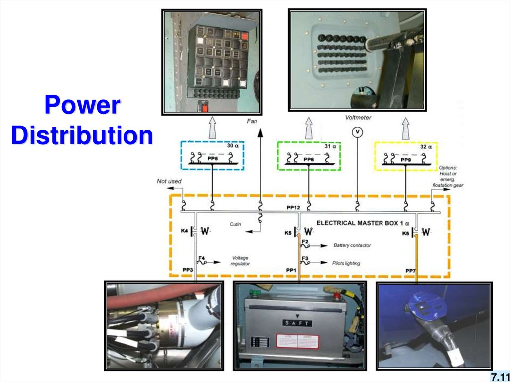
Power Distribution ………………..…….…………………………..……… 7.11
Direct Battery Power …………………...………………………………….. 7.12
Direct Battery Switch - Light Logic ….………………………………….. 7.13
Electrical System Limitations…..………………………………………… 7.14
Smoke in the Cockpit / Cargo - Source Not Identified ………. 7.19 & 7.23
Smoke in the Cockpit / Cargo - Source Identified …………………….. 7.26
Battery Temperature Warning Light …………………………………….. 7.32
Battery Caution Light ……………………………………………………… 7.41
Generator Caution Light …...…………………...………………… 7.54 & 7.55
Review Questions ………………………………………………………….. 7.56
7.2
3.
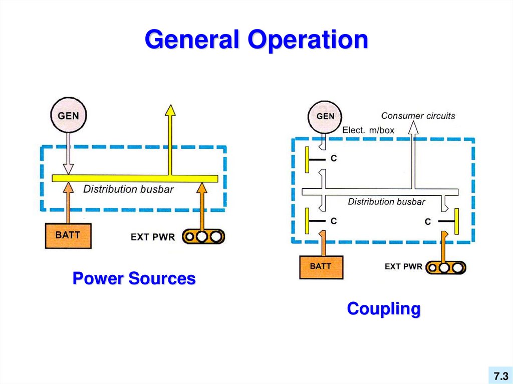
General OperationPower Sources
Coupling
7.3
4.
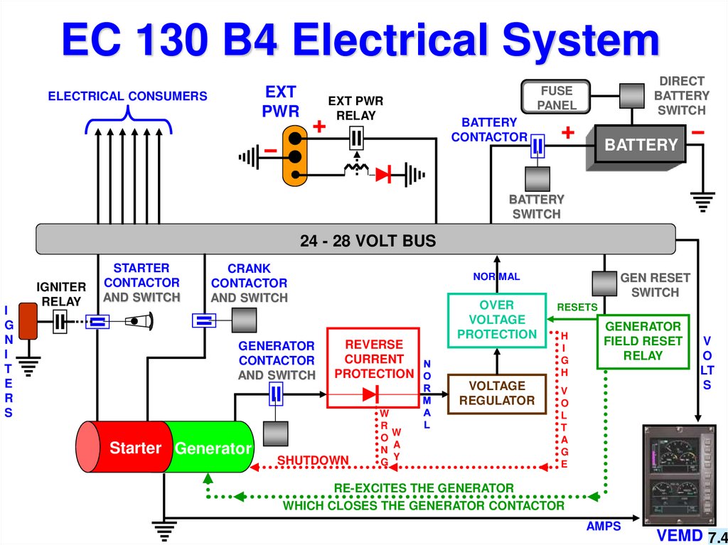
EC 130 B4 Electrical SystemEXT
PWR
ELECTRICAL CONSUMERS
EXT PWR
RELAY
DIRECT
BATTERY
SWITCH
FUSE
PANEL
BATTERY
CONTACTOR
BATTERY
BATTERY
SWITCH
24 - 28 VOLT BUS
I
G
N
I
T
E
R
S
IGNITER
RELAY
STARTER
CONTACTOR
AND SWITCH
CRANK
CONTACTOR
AND SWITCH
GENERATOR
CONTACTOR
AND SWITCH
Starter Generator
NOR MAL
REVERSE
CURRENT
PROTECTION
SHUTDOWN
OVER
VOLTAGE
PROTECTION
VOLTAGE
REGULATOR
W
R
W
O
A
N
Y
G
GEN RESET
SWITCH
RESETS
H
I
G
H
GENERATOR
FIELD RESET
RELAY
V
O
L
T
A
G
E
V
O
LT
S
RE-EXCITES THE GENERATOR
WHICH CLOSES THE GENERATOR CONTACTOR
AMPS
VEMD 7.4
5.
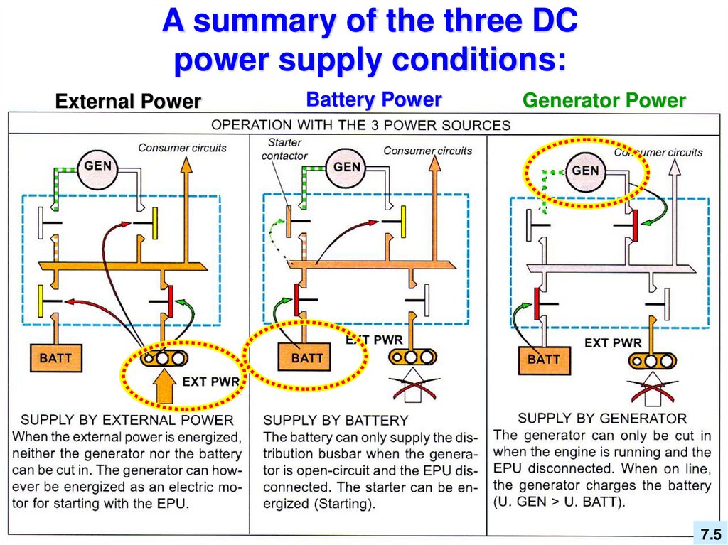
A summary of the three DCpower supply conditions:
External Power
Battery Power
Generator Power
7.5
6.
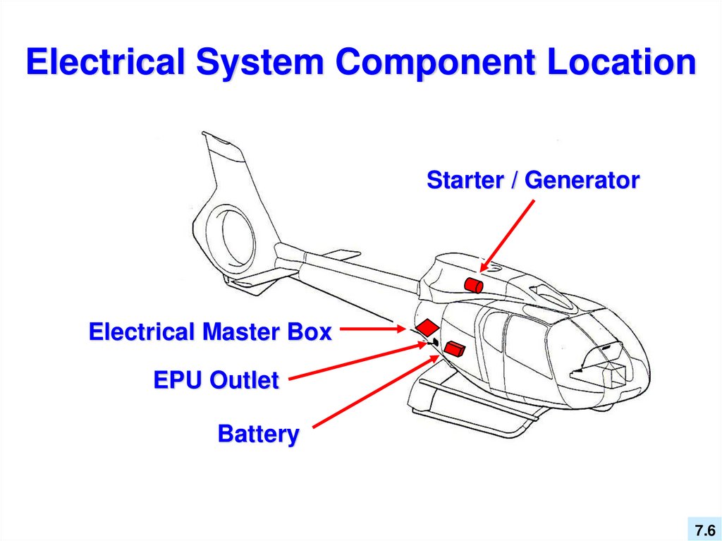
Electrical System Component LocationStarter / Generator
Electrical Master Box
EPU Outlet
Battery
7.6
7. Pilot’s view of the Electrical System
BATTGENE
EXT PWR
BATT.
GENE
BATT
TEMP
GENE
RESET
CRANK
DIRECT
BATT.
MASTER
SW
7.7
8.
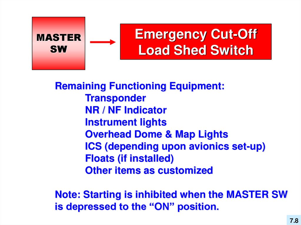
MASTERSW
Emergency Cut-Off
Load Shed Switch
Remaining Functioning Equipment:
Transponder
NR / NF Indicator
Instrument lights
Overhead Dome & Map Lights
ICS (depending upon avionics set-up)
Floats (if installed)
Other items as customized
Note: Starting is inhibited when the MASTER SW
is depressed to the “ON” position.
7.8
9. Vehicle and Engine Multifunction Display
The V.E.M.D.displays the
priority aircraft
voltage and
amperage.
7.9
10.
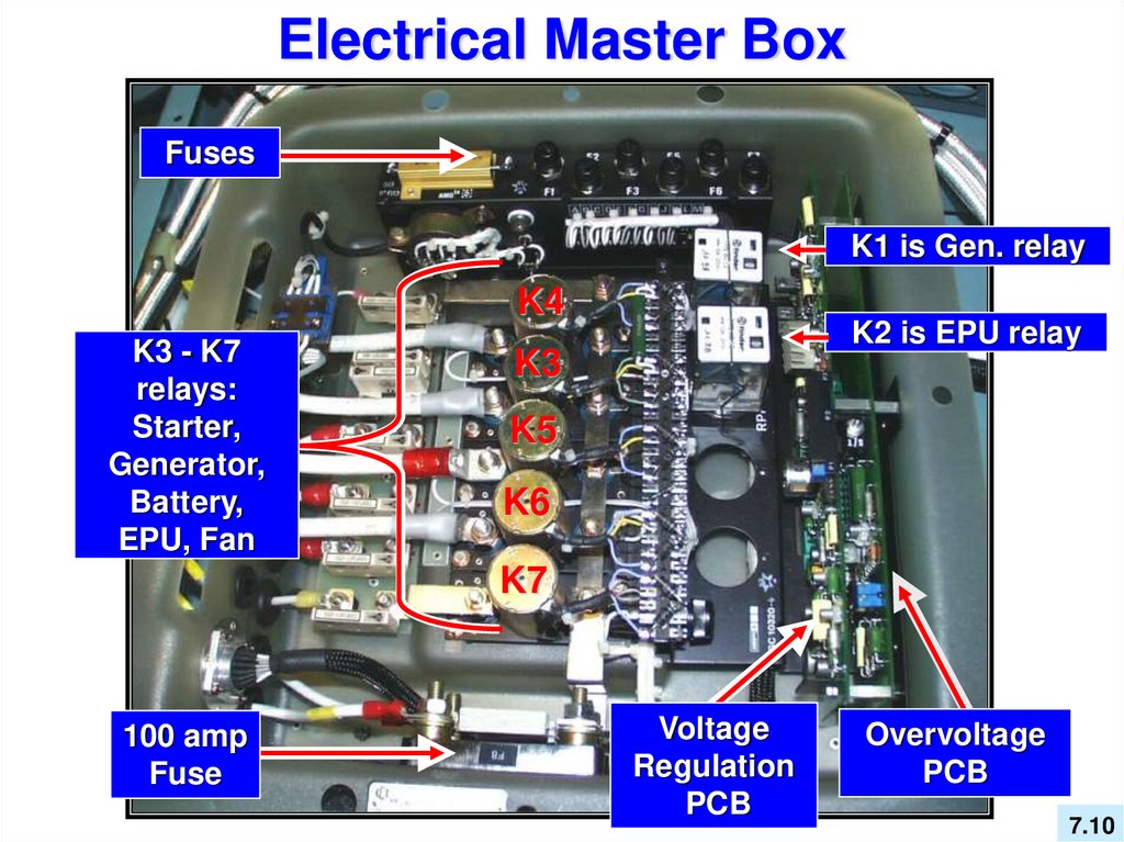
Electrical Master BoxFuses
K1 is Gen. relay
K4
K3 - K7
relays:
Starter,
Generator,
Battery,
EPU, Fan
K2 is EPU relay
K3
K5
K6
K7
100 amp
Fuse
Voltage
Regulation
PCB
Overvoltage
PCB
7.10
11.
PowerDistribution
7.11
12.
Direct Battery Power16 ALPHA
DIRECT
BATT.
Remaining
Equipment:
Transponder
NR / NF Indicator
Instrument lights
Overhead Dome & Map Lights
ICS (depending upon avionics set-up)
Floats (if installed)
Other items as customized
7.12
13.
Direct Battery Switch - Light LogicThe DIRECT BATTERY pushbutton brings power to
certain components directly from the battery. The Direct
Battery pushbutton MUST be depressed to the “ON”
position to activate the Transponder and Nf indicator.
Normally, both the EXT PWR / BAT and the
DIRECT BATTERY pushbuttons are engaged.
When both are engaged, the DIRECT BATTERY
pushbutton will not be illuminated.
If only the DIRECT BATTERY pushbutton is
depressed to the “ON” position, then the lights
are illuminated.
DIRECT
BATT.
DIRECT
BATT.
7.13
14. Electrical System Limitations
MaximumVoltage....… 31.5 Volts
Rated Voltage
Range..…. 26-29 Volts
Maximum
Current....…. 150 Amps
(Optional …… 200 Amps)
Flight Manual - Limitations Section - Page 2 - 9
7.14
15.
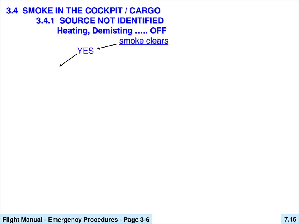
3.4 SMOKE IN THE COCKPIT / CARGO3.4.1 SOURCE NOT IDENTIFIED
Heating, Demisting ….. OFF
smoke clears
YES
Flight Manual - Emergency Procedures - Page 3-6
7.15
16.
3.4 SMOKE IN THE COCKPIT / CARGO3.4.1 SOURCE NOT IDENTIFIED
Heating, Demisting ….. OFF
smoke clears
YES
CONTINUE FLIGHT
depending on
weather conditions
Flight Manual - Emergency Procedures - Page 3-6
7.16
17.
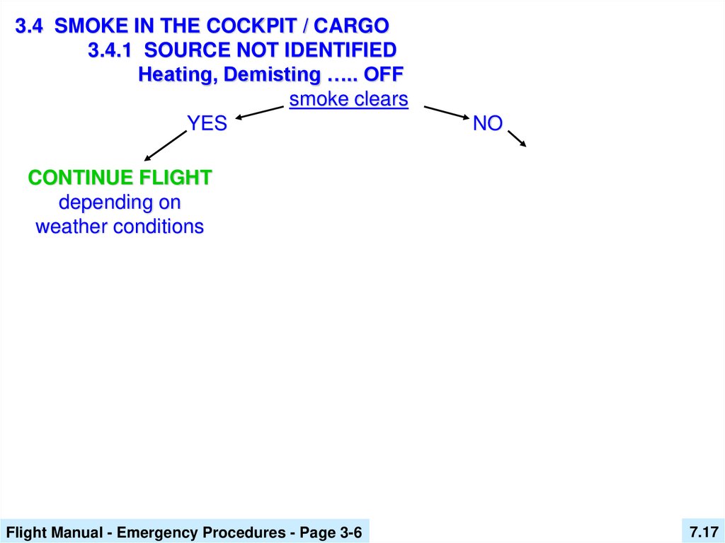
3.4 SMOKE IN THE COCKPIT / CARGO3.4.1 SOURCE NOT IDENTIFIED
Heating, Demisting ….. OFF
smoke clears
YES
NO
CONTINUE FLIGHT
depending on
weather conditions
Flight Manual - Emergency Procedures - Page 3-6
7.17
18.
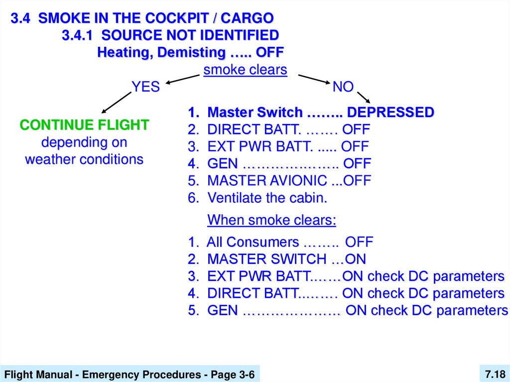
3.4 SMOKE IN THE COCKPIT / CARGO3.4.1 SOURCE NOT IDENTIFIED
Heating, Demisting ….. OFF
smoke clears
YES
CONTINUE FLIGHT
depending on
weather conditions
NO
1. Master Switch …….. DEPRESSED
2. DIRECT BATT. ……. OFF
3. EXT PWR BATT. ..... OFF
4. GEN ………….…….. OFF
5. MASTER AVIONIC ...OFF
6. Ventilate the cabin.
When smoke clears:
1. All Consumers …….. OFF
2. MASTER SWITCH …ON
3. EXT PWR BATT.……ON check DC parameters
4. DIRECT BATT..……. ON check DC parameters
5. GEN ………………… ON check DC parameters
Flight Manual - Emergency Procedures - Page 3-6
7.18
19.
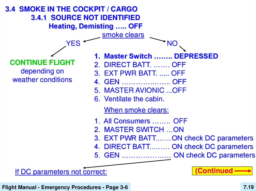
3.4 SMOKE IN THE COCKPIT / CARGO3.4.1 SOURCE NOT IDENTIFIED
Heating, Demisting ….. OFF
smoke clears
YES
CONTINUE FLIGHT
depending on
weather conditions
NO
1. Master Switch …….. DEPRESSED
2. DIRECT BATT. ……. OFF
3. EXT PWR BATT. ..... OFF
4. GEN ………….…….. OFF
5. MASTER AVIONIC ...OFF
6. Ventilate the cabin.
When smoke clears:
1. All Consumers …….. OFF
2. MASTER SWITCH …ON
3. EXT PWR BATT.……ON check DC parameters
4. DIRECT BATT..……. ON check DC parameters
5. GEN ………………… ON check DC parameters
If DC parameters not correct:
Flight Manual - Emergency Procedures - Page 3-6
(Continued
7.19
20.
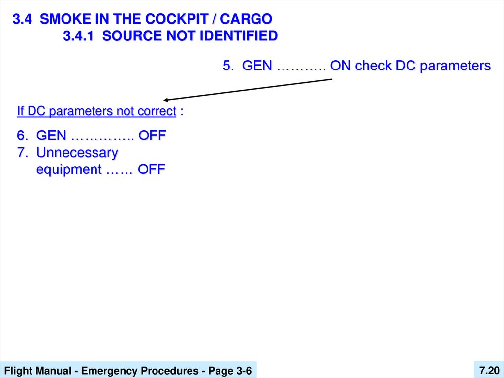
3.4 SMOKE IN THE COCKPIT / CARGO3.4.1 SOURCE NOT IDENTIFIED
5. GEN ……….. ON check DC parameters
If DC parameters not correct :
6. GEN ………….. OFF
7. Unnecessary
equipment …… OFF
Flight Manual - Emergency Procedures - Page 3-6
7.20
21.
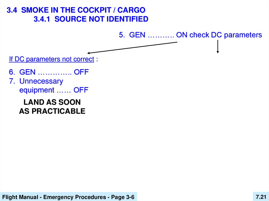
3.4 SMOKE IN THE COCKPIT / CARGO3.4.1 SOURCE NOT IDENTIFIED
5. GEN ……….. ON check DC parameters
If DC parameters not correct :
6. GEN ………….. OFF
7. Unnecessary
equipment …… OFF
LAND AS SOON
AS PRACTICABLE
Flight Manual - Emergency Procedures - Page 3-6
7.21
22.
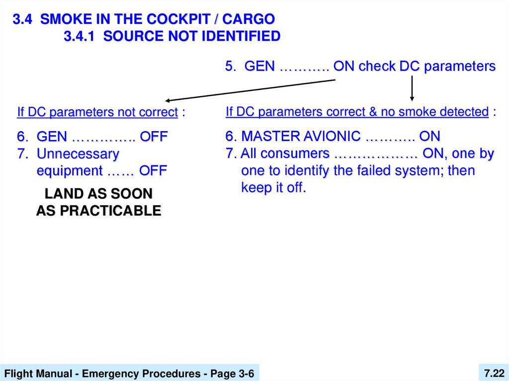
3.4 SMOKE IN THE COCKPIT / CARGO3.4.1 SOURCE NOT IDENTIFIED
5. GEN ……….. ON check DC parameters
If DC parameters not correct :
If DC parameters correct & no smoke detected :
6. GEN ………….. OFF
7. Unnecessary
equipment …… OFF
6. MASTER AVIONIC ……….. ON
7. All consumers ……………… ON, one by
one to identify the failed system; then
keep it off.
LAND AS SOON
AS PRACTICABLE
Flight Manual - Emergency Procedures - Page 3-6
7.22
23.
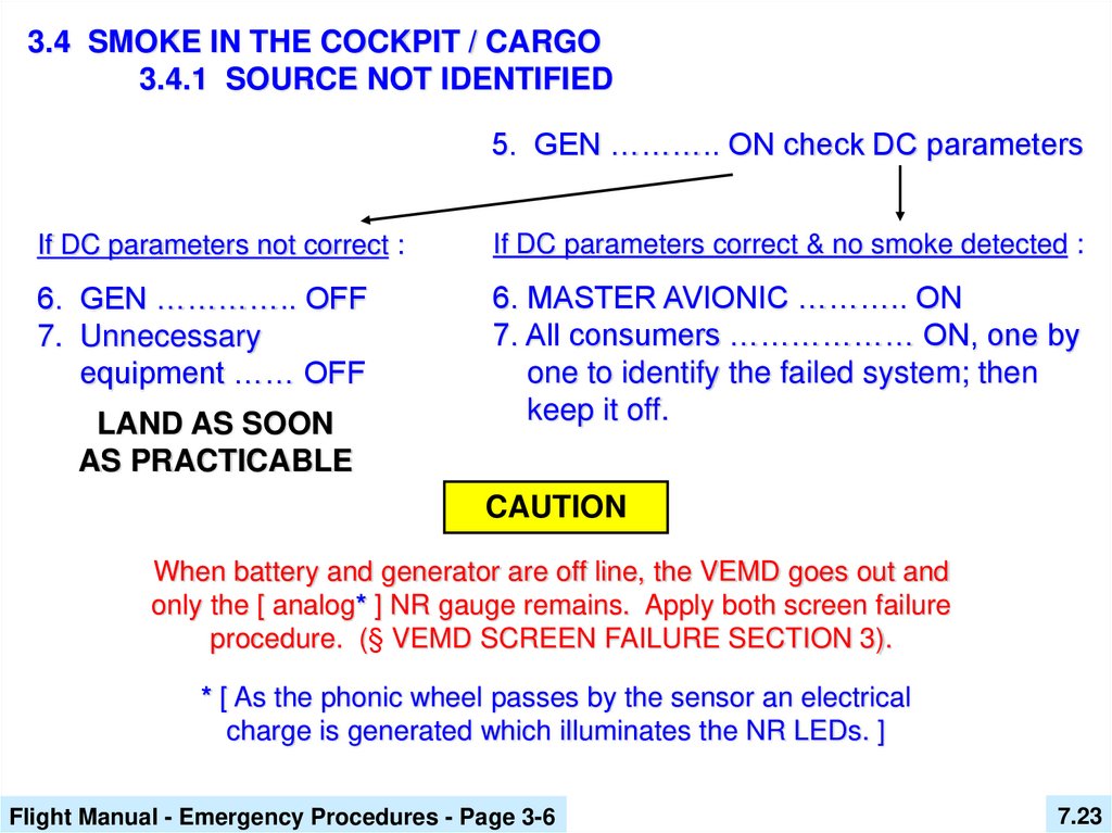
3.4 SMOKE IN THE COCKPIT / CARGO3.4.1 SOURCE NOT IDENTIFIED
5. GEN ……….. ON check DC parameters
If DC parameters not correct :
If DC parameters correct & no smoke detected :
6. GEN ………….. OFF
7. Unnecessary
equipment …… OFF
6. MASTER AVIONIC ……….. ON
7. All consumers ……………… ON, one by
one to identify the failed system; then
keep it off.
LAND AS SOON
AS PRACTICABLE
CAUTION
When battery and generator are off line, the VEMD goes out and
only the [ analog* ] NR gauge remains. Apply both screen failure
procedure. (§ VEMD SCREEN FAILURE SECTION 3).
* [ As the phonic wheel passes by the sensor an electrical
charge is generated which illuminates the NR LEDs. ]
Flight Manual - Emergency Procedures - Page 3-6
7.23
24.
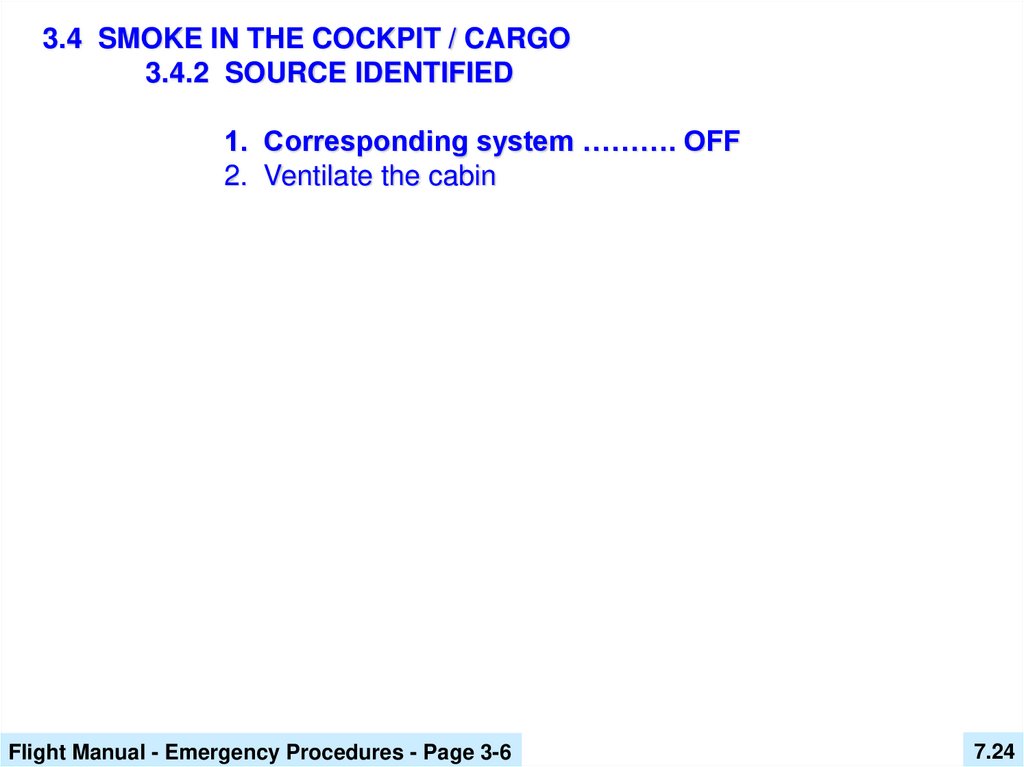
3.4 SMOKE IN THE COCKPIT / CARGO3.4.2 SOURCE IDENTIFIED
1. Corresponding system ………. OFF
2. Ventilate the cabin
Flight Manual - Emergency Procedures - Page 3-6
7.24
25.
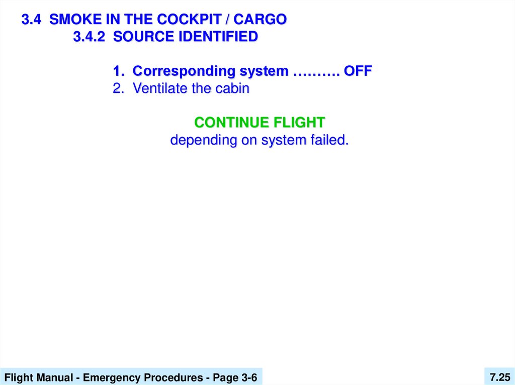
3.4 SMOKE IN THE COCKPIT / CARGO3.4.2 SOURCE IDENTIFIED
1. Corresponding system ………. OFF
2. Ventilate the cabin
CONTINUE FLIGHT
depending on system failed.
Flight Manual - Emergency Procedures - Page 3-6
7.25
26.
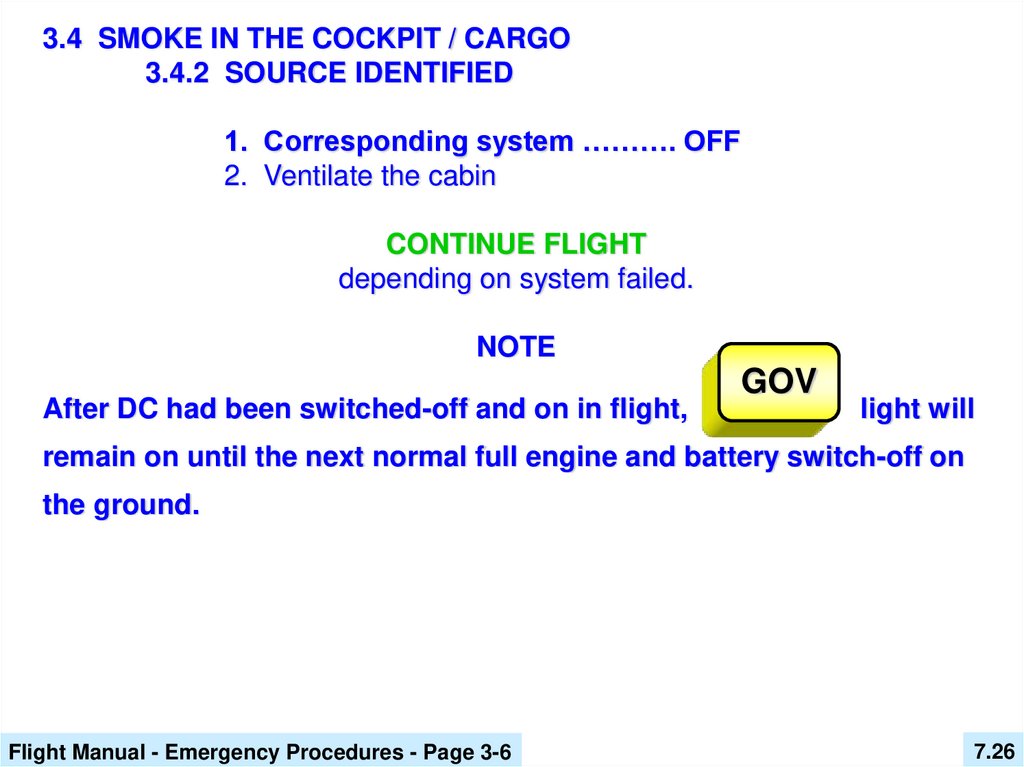
3.4 SMOKE IN THE COCKPIT / CARGO3.4.2 SOURCE IDENTIFIED
1. Corresponding system ………. OFF
2. Ventilate the cabin
CONTINUE FLIGHT
depending on system failed.
NOTE
After DC had been switched-off and on in flight,
GOV
light will
remain on until the next normal full engine and battery switch-off on
the ground.
Flight Manual - Emergency Procedures - Page 3-6
7.26
27.
WARNING PANELCORRECTIVE ACTIONS
BATT
TEMP
Maximum
battery
temperature.
Flight Manual - Emergency Procedures - Page 3-16
7.27
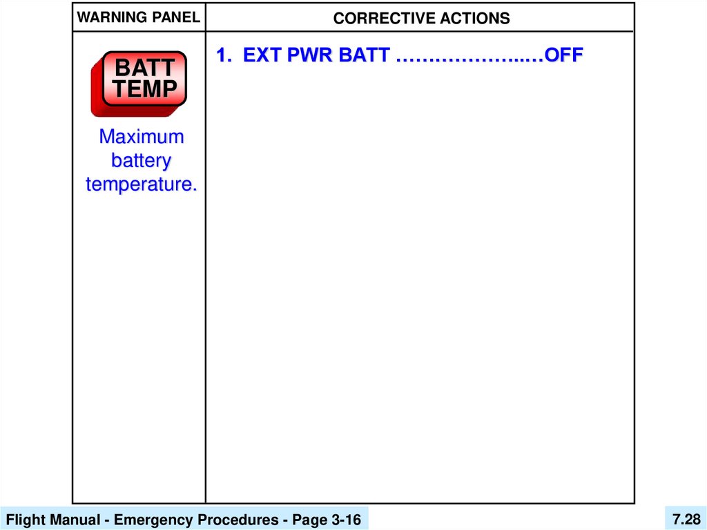
28.
WARNING PANELBATT
TEMP
CORRECTIVE ACTIONS
1. EXT PWR BATT ………………..…OFF
Maximum
battery
temperature.
Flight Manual - Emergency Procedures - Page 3-16
7.28
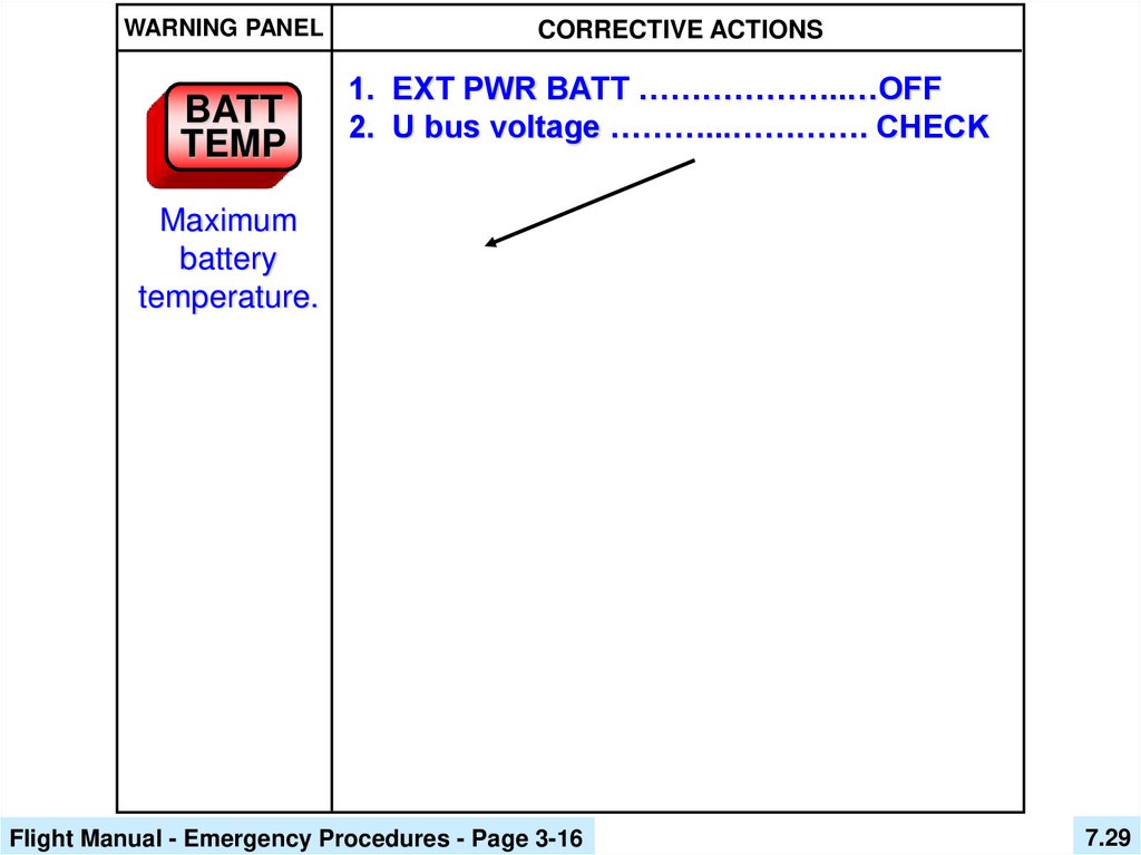
29.
WARNING PANELBATT
TEMP
CORRECTIVE ACTIONS
1. EXT PWR BATT ………………..…OFF
2. U bus voltage ………...…………. CHECK
Maximum
battery
temperature.
Flight Manual - Emergency Procedures - Page 3-16
7.29
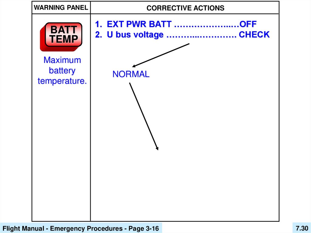
30.
WARNING PANELBATT
TEMP
Maximum
battery
temperature.
CORRECTIVE ACTIONS
1. EXT PWR BATT ………………..…OFF
2. U bus voltage ………...…………. CHECK
NORMAL
Flight Manual - Emergency Procedures - Page 3-16
7.30
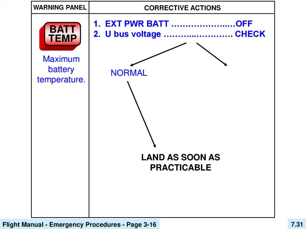
31.
WARNING PANELBATT
TEMP
Maximum
battery
temperature.
CORRECTIVE ACTIONS
1. EXT PWR BATT ………………..…OFF
2. U bus voltage ………...…………. CHECK
NORMAL
LAND AS SOON AS
PRACTICABLE
Flight Manual - Emergency Procedures - Page 3-16
7.31
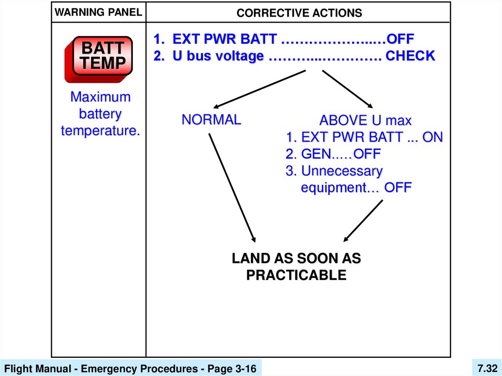
32.
WARNING PANELBATT
TEMP
Maximum
battery
temperature.
CORRECTIVE ACTIONS
1. EXT PWR BATT ………………..…OFF
2. U bus voltage ………...…………. CHECK
NORMAL
ABOVE U max
1. EXT PWR BATT ... ON
2. GEN..…OFF
3. Unnecessary
equipment… OFF
LAND AS SOON AS
PRACTICABLE
Flight Manual - Emergency Procedures - Page 3-16
7.32
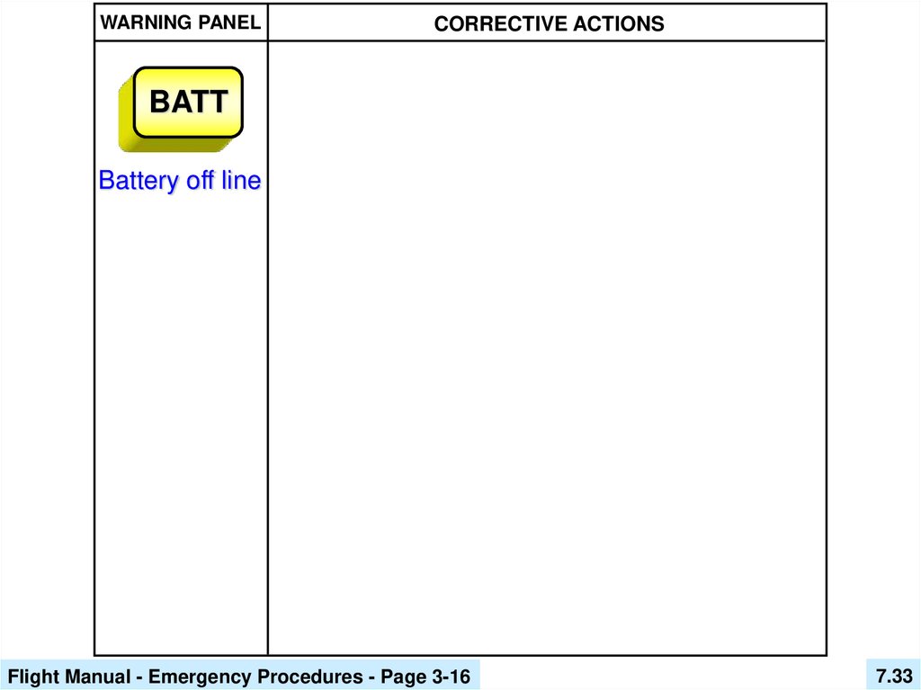
33.
WARNING PANELCORRECTIVE ACTIONS
BATT
Battery off line
Flight Manual - Emergency Procedures - Page 3-16
7.33
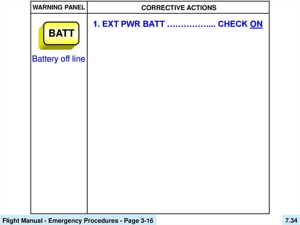
34.
WARNING PANELCORRECTIVE ACTIONS
1. EXT PWR BATT ……………... CHECK ON
BATT
Battery off line
Flight Manual - Emergency Procedures - Page 3-16
7.34
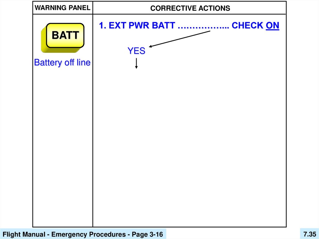
35.
WARNING PANELCORRECTIVE ACTIONS
1. EXT PWR BATT ……………... CHECK ON
BATT
YES
Battery off line
Flight Manual - Emergency Procedures - Page 3-16
7.35
36.
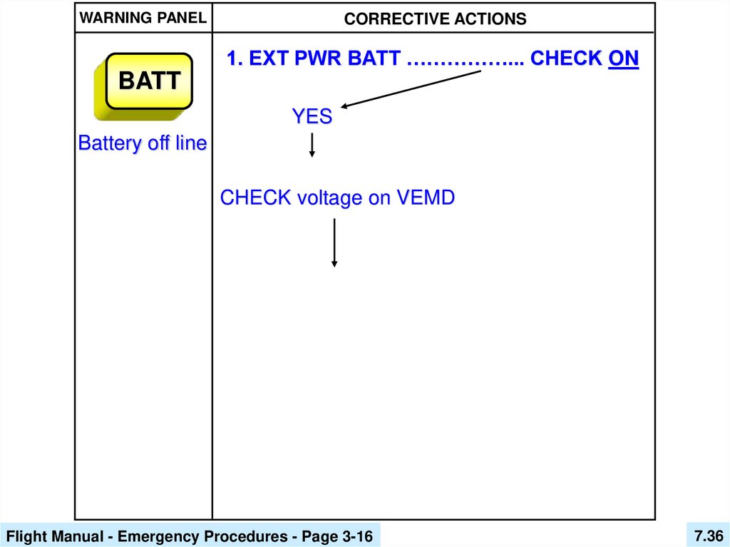
WARNING PANELCORRECTIVE ACTIONS
1. EXT PWR BATT ……………... CHECK ON
BATT
YES
Battery off line
CHECK voltage on VEMD
Flight Manual - Emergency Procedures - Page 3-16
7.36
37.
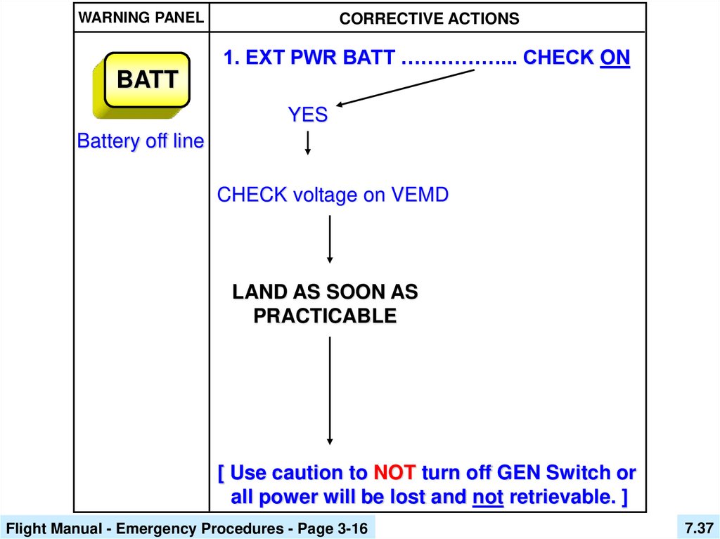
WARNING PANELCORRECTIVE ACTIONS
1. EXT PWR BATT ……………... CHECK ON
BATT
YES
Battery off line
CHECK voltage on VEMD
LAND AS SOON AS
PRACTICABLE
[ Use caution to NOT turn off GEN Switch or
all power will be lost and not retrievable. ]
Flight Manual - Emergency Procedures - Page 3-16
7.37
38.
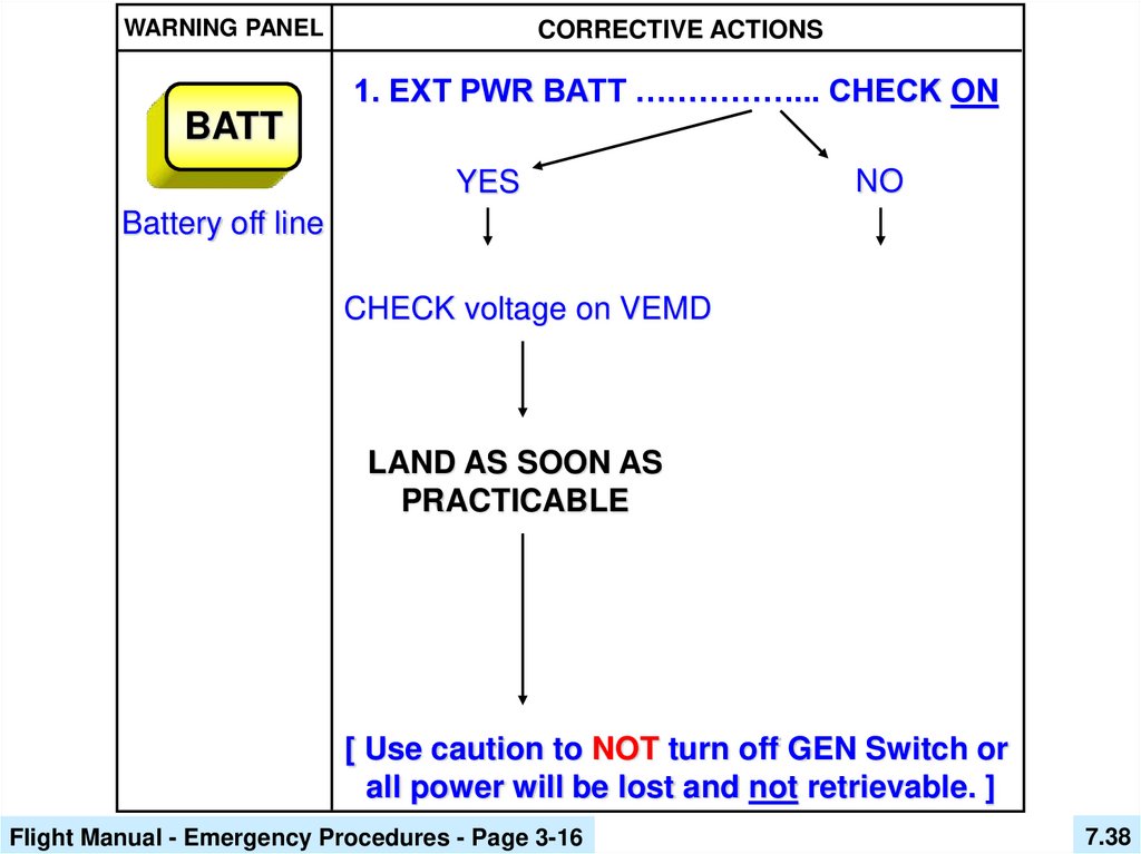
WARNING PANELCORRECTIVE ACTIONS
1. EXT PWR BATT ……………... CHECK ON
BATT
YES
NO
Battery off line
CHECK voltage on VEMD
LAND AS SOON AS
PRACTICABLE
[ Use caution to NOT turn off GEN Switch or
all power will be lost and not retrievable. ]
Flight Manual - Emergency Procedures - Page 3-16
7.38
39.
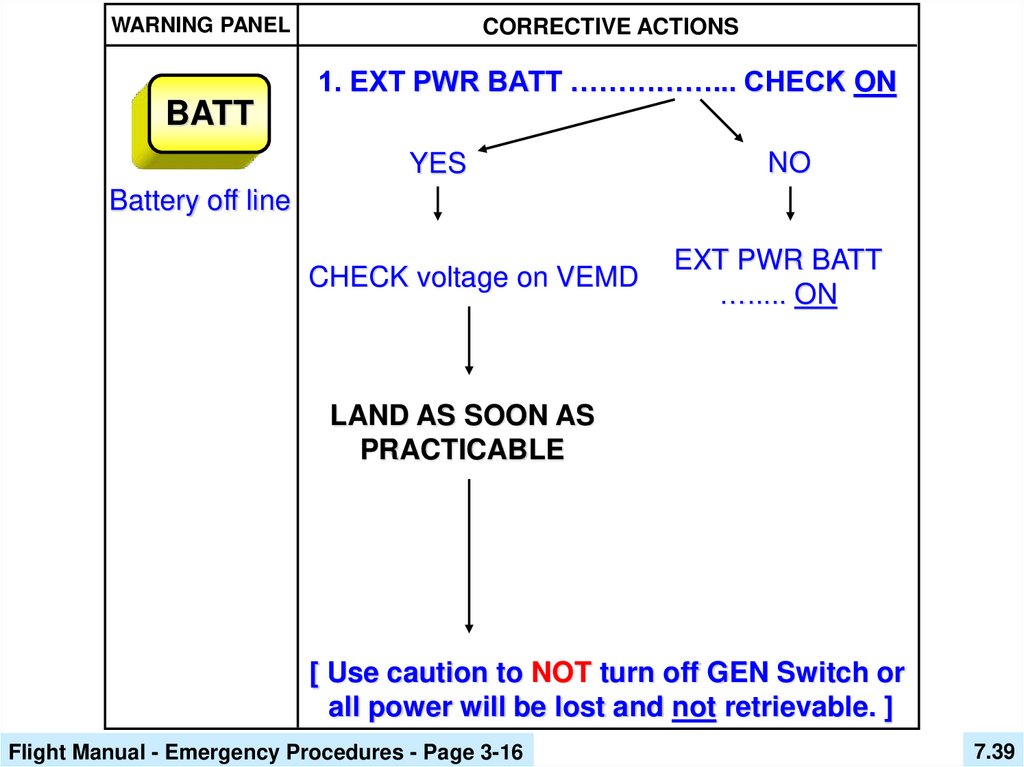
WARNING PANELCORRECTIVE ACTIONS
1. EXT PWR BATT ……………... CHECK ON
BATT
YES
NO
Battery off line
CHECK voltage on VEMD
EXT PWR BATT
…..... ON
LAND AS SOON AS
PRACTICABLE
[ Use caution to NOT turn off GEN Switch or
all power will be lost and not retrievable. ]
Flight Manual - Emergency Procedures - Page 3-16
7.39
40.
WARNING PANELCORRECTIVE ACTIONS
1. EXT PWR BATT ……………... CHECK ON
BATT
YES
NO
Battery off line
CHECK voltage on VEMD
EXT PWR BATT
…..... ON
BATT
LAND AS SOON AS
PRACTICABLE
Goes out
[ Use caution to NOT turn off GEN Switch or
all power will be lost and not retrievable. ]
Flight Manual - Emergency Procedures - Page 3-16
7.40
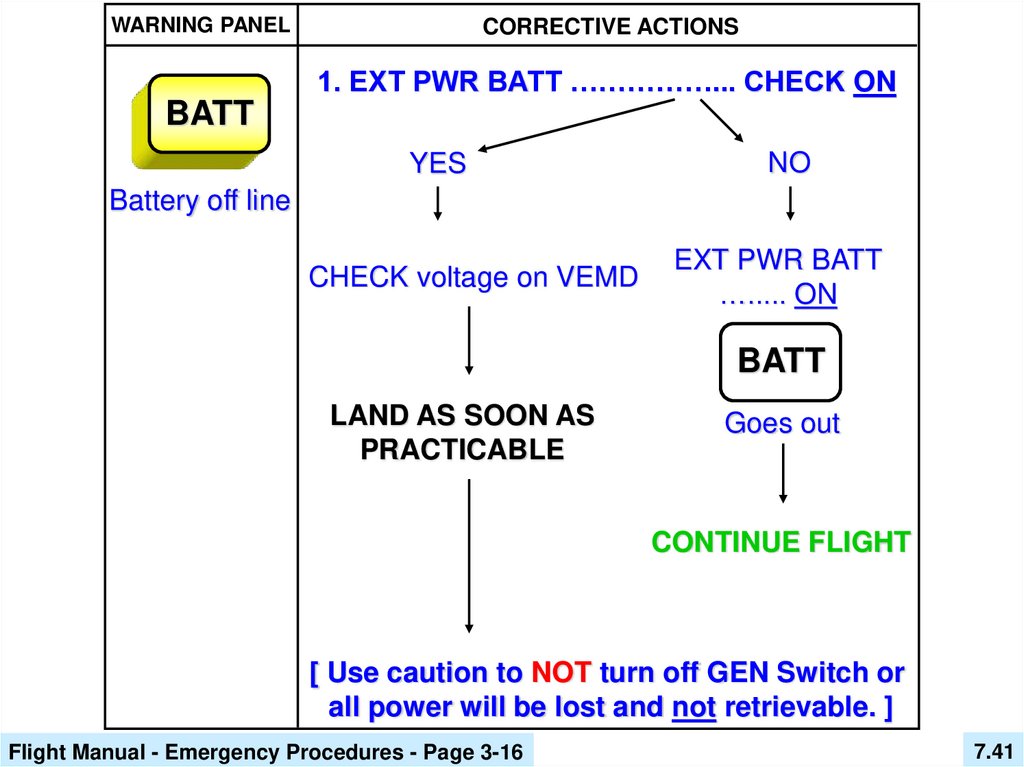
41.
WARNING PANELCORRECTIVE ACTIONS
1. EXT PWR BATT ……………... CHECK ON
BATT
YES
NO
Battery off line
CHECK voltage on VEMD
EXT PWR BATT
…..... ON
BATT
LAND AS SOON AS
PRACTICABLE
Goes out
CONTINUE FLIGHT
[ Use caution to NOT turn off GEN Switch or
all power will be lost and not retrievable. ]
Flight Manual - Emergency Procedures - Page 3-16
7.41
42.
WARNING PANELCORRECTIVE ACTIONS
GENE
DC Generator
off line
Flight Manual - Emergency Procedures - Page 3-17
7.42
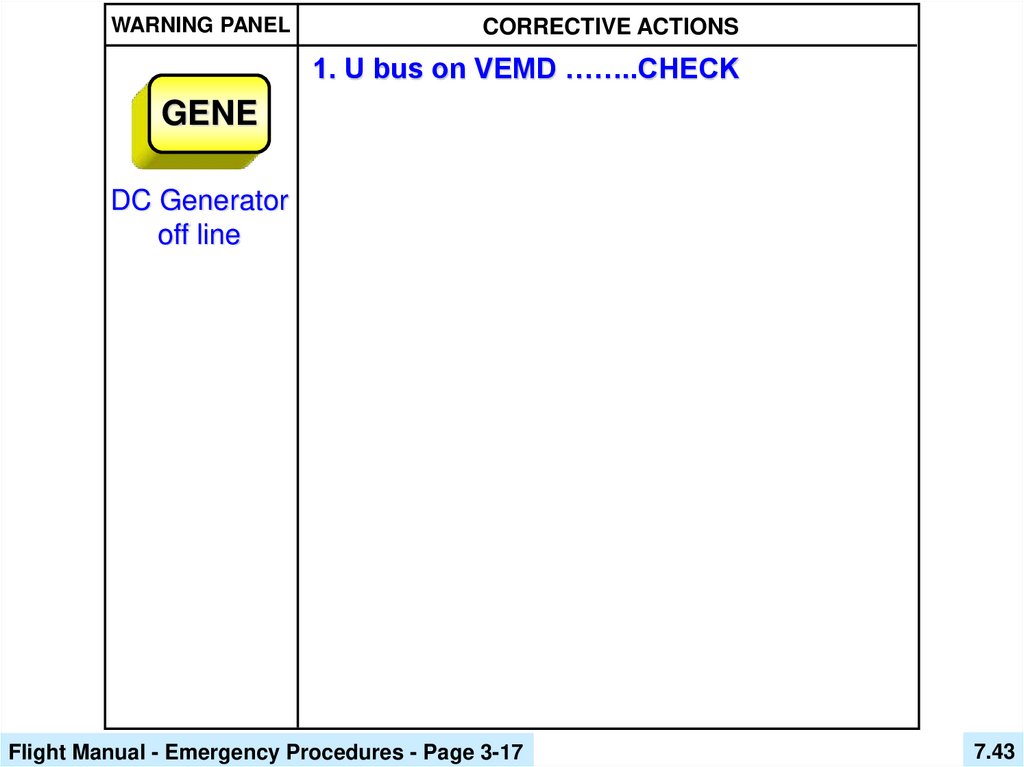
43.
WARNING PANELCORRECTIVE ACTIONS
1. U bus on VEMD ……..CHECK
GENE
DC Generator
off line
Flight Manual - Emergency Procedures - Page 3-17
7.43
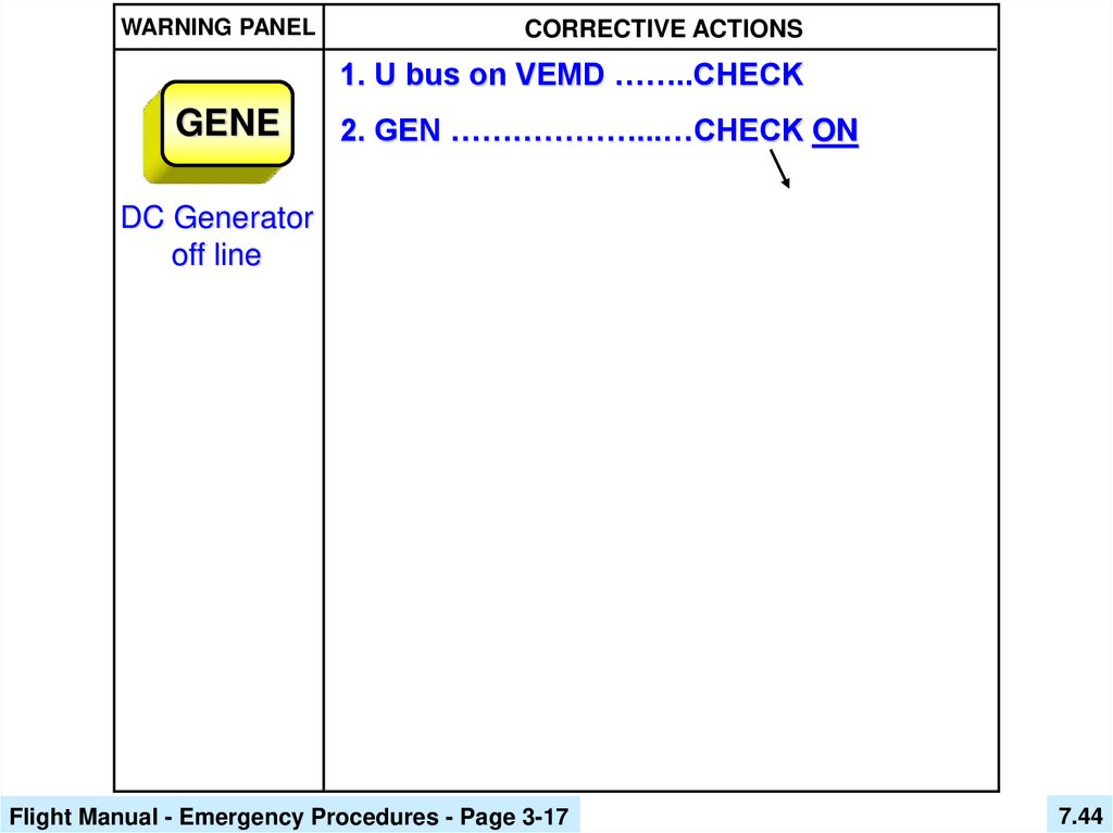
44.
WARNING PANELCORRECTIVE ACTIONS
1. U bus on VEMD ……..CHECK
GENE
2. GEN ………………...…CHECK ON
DC Generator
off line
Flight Manual - Emergency Procedures - Page 3-17
7.44
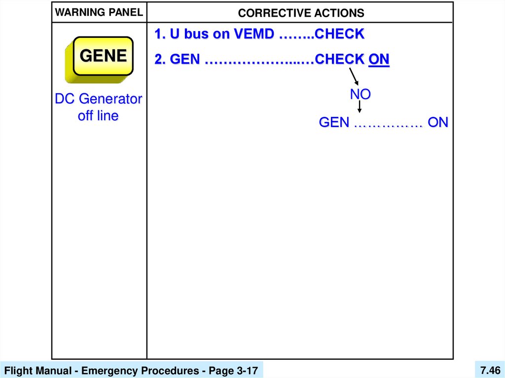
45.
WARNING PANELCORRECTIVE ACTIONS
1. U bus on VEMD ……..CHECK
GENE
2. GEN ………………...…CHECK ON
DC Generator
off line
Flight Manual - Emergency Procedures - Page 3-17
NO
7.45
46.
WARNING PANELCORRECTIVE ACTIONS
1. U bus on VEMD ……..CHECK
GENE
2. GEN ………………...…CHECK ON
DC Generator
off line
Flight Manual - Emergency Procedures - Page 3-17
NO
GEN …………… ON
7.46
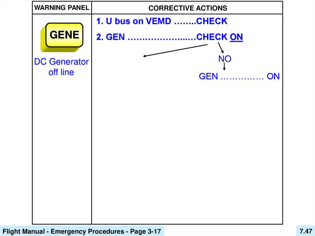
47.
WARNING PANELCORRECTIVE ACTIONS
1. U bus on VEMD ……..CHECK
GENE
2. GEN ………………...…CHECK ON
DC Generator
off line
Flight Manual - Emergency Procedures - Page 3-17
NO
GEN …………… ON
7.47
48.
WARNING PANELCORRECTIVE ACTIONS
1. U bus on VEMD ……..CHECK
GENE
DC Generator
off line
2. GEN ………………...…CHECK ON
YES
Flight Manual - Emergency Procedures - Page 3-17
NO
GEN …………… ON
7.48
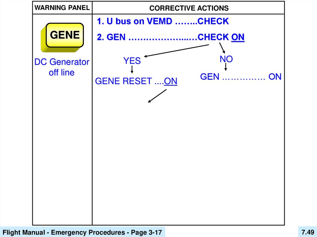
49.
WARNING PANELCORRECTIVE ACTIONS
1. U bus on VEMD ……..CHECK
GENE
DC Generator
off line
2. GEN ………………...…CHECK ON
YES
GENE RESET ....ON
Flight Manual - Emergency Procedures - Page 3-17
NO
GEN …………… ON
7.49
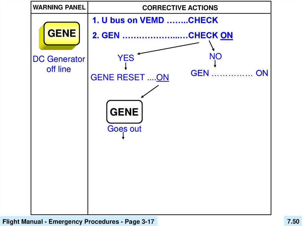
50.
WARNING PANELCORRECTIVE ACTIONS
1. U bus on VEMD ……..CHECK
GENE
DC Generator
off line
2. GEN ………………...…CHECK ON
YES
GENE RESET ....ON
NO
GEN …………… ON
GENE
Goes out
Flight Manual - Emergency Procedures - Page 3-17
7.50
51.
WARNING PANELCORRECTIVE ACTIONS
1. U bus on VEMD ……..CHECK
GENE
DC Generator
off line
2. GEN ………………...…CHECK ON
YES
GENE RESET ....ON
NO
GEN …………… ON
GENE
Goes out
CONTINUE FLIGHT
Flight Manual - Emergency Procedures - Page 3-17
7.51
52.
WARNING PANELCORRECTIVE ACTIONS
1. U bus on VEMD ……..CHECK
GENE
DC Generator
off line
2. GEN ………………...…CHECK ON
YES
GENE RESET ....ON
GENE
Goes out
NO
GEN …………… ON
GENE
Remains on
CONTINUE FLIGHT
Flight Manual - Emergency Procedures - Page 3-17
7.52
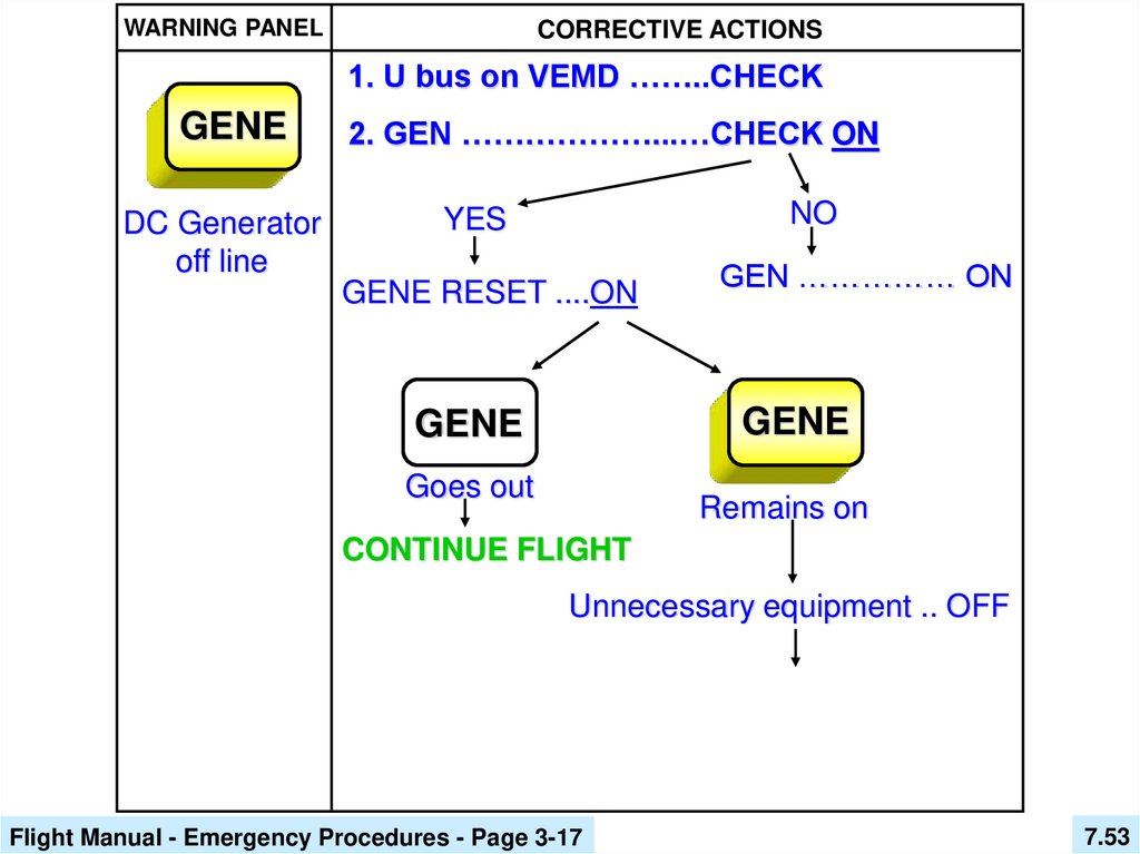
53.
WARNING PANELCORRECTIVE ACTIONS
1. U bus on VEMD ……..CHECK
GENE
DC Generator
off line
2. GEN ………………...…CHECK ON
NO
YES
GENE RESET ....ON
GEN …………… ON
GENE
GENE
Goes out
Remains on
CONTINUE FLIGHT
Unnecessary equipment .. OFF
Flight Manual - Emergency Procedures - Page 3-17
7.53
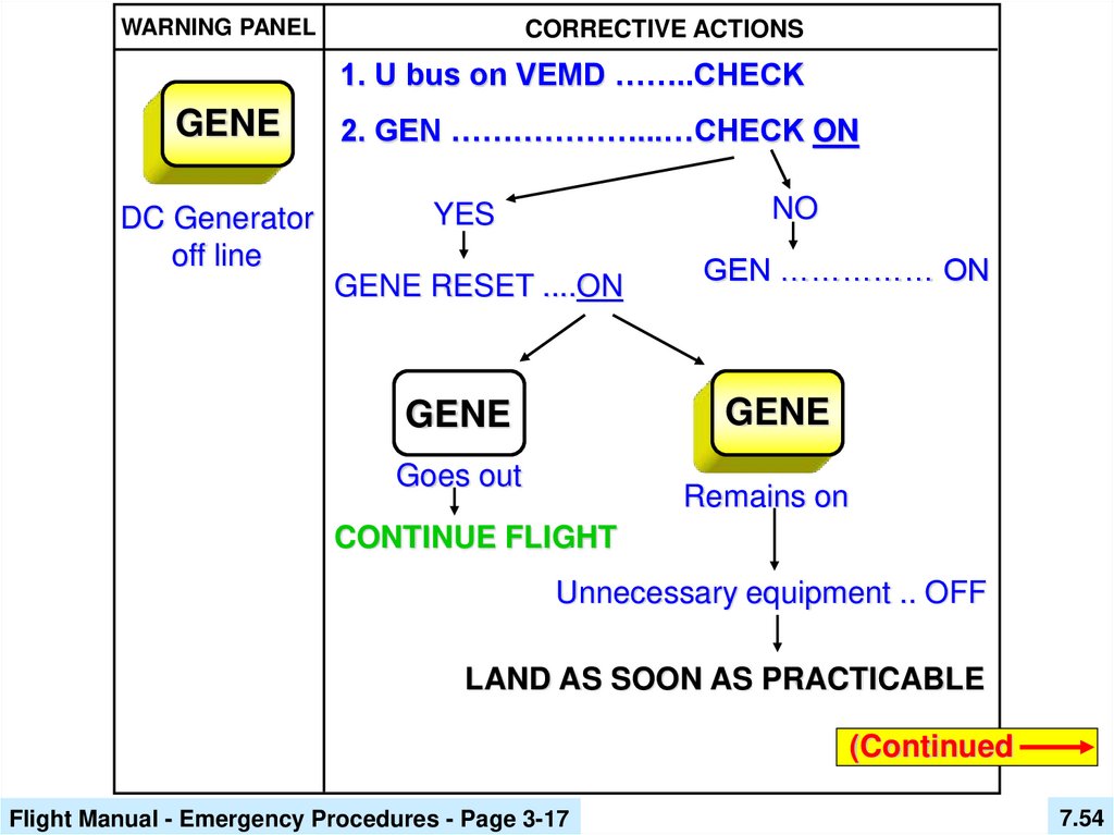
54.
WARNING PANELCORRECTIVE ACTIONS
1. U bus on VEMD ……..CHECK
GENE
DC Generator
off line
2. GEN ………………...…CHECK ON
NO
YES
GENE RESET ....ON
GEN …………… ON
GENE
GENE
Goes out
Remains on
CONTINUE FLIGHT
Unnecessary equipment .. OFF
LAND AS SOON AS PRACTICABLE
(Continued
Flight Manual - Emergency Procedures - Page 3-17
7.54
55.
WARNING PANELGENE
CORRECTIVE ACTIONS
GENE
GENE
Goes out
Remains on
DC Generator
CONTINUE FLIGHT
off line
Unnecessary equipment .. OFF
LAND AS SOON AS PRACTICABLE
CAUTION
If the battery fails, the VEMD will go out and only
the analog NR gauge will remain.
[ As the phonic wheel passes by the sensor an electrical
charge is generated which illuminates the NR LEDs. ]
Maximum flight time on battery:
• day: 50 minutes (1 VHF 1 VOR)
• night: 20 minutes (same as day plus instrument
lighting and external lights).
Flight Manual - Emergency Procedures - Page 3-17
7.55
56. Review Questions
7.5657.
55. What are the basic components ofthe aircraft electrical system?
A. Battery, generator, EPU receptacle,
fuses, and relays.
58.
56. What caution / warning lights monitorthe aircraft electrical system?
B.
BATT
TEMP
BATT
GENE
59.
57. What items monitor the electricalsystem?
D. VEMD voltmeter and amp meter.
60.
58. What pushbuttons / switches are used toengage (or disengage) electrical systems?
D. BAT switch, GEN switch, GEN RESET,
DIRECT BATT, & MASTER SW.
61.
59. Where is the electrical master boxlocated?
C. Floor of aft cargo area.
62.
60. What must the pilot press (or switch)on to energize the PP12 (distribution bus
bar) by an EPU?
B. EXT PWR / BAT pushbutton.
63.
61. What is the difference in switch usagewhen starting the helicopter using an EPU
versus the battery?
C. Only small children fall for this one as
there is no difference at all.
64.
62. What caution / warning lights will beilluminated for an EPU start as opposed
to a battery start?
D. The BATT light will be illuminated.
65.
63. When does the generator come on line?C. When Generator voltage exceeds
Battery voltage by .5 volts.
66.
64. What does the U/BUS (Utilization Bus)on the VEMD display?
B. Battery or Generator voltage.
67.
65. Will the helicopter start if the MASTERSW is depressed to the “ON” condition?
A. No
68.
66. What electrical items will continue tooperate if the MASTER SW is depressed
to the “ON” condition?
C. Transponder, NR / Nf, instrument
lights, overhead dome & map lights,
and in some aircraft, ICS and floats.
69.
67. If you use an External Power Unit tostart the EC130 B4 what are the
recommended maximum voltage and
amperage values (standard aircraft) ?
D. 31.5 Volts and 150 Amps maximum
70.
EC 130 B4Initial Pilot Ground School
End of Chapter 7
Electrical System