


 Электроника
Похожие презентации:


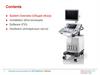






Semi-auto Chemistry Analyzer Service Training
1.
BA-88ASemi-auto Chemistry Analyzer Service Training
Biochemistry Global Support Department
Service@mindray.com
Version 2.0
No. MSH-13023-BA-88A
© 2012 Mindray Confidential
2.
ContentsSystem Introduction
Operation procedure
Optical System
Liquid System
Hardware System
Maintenance
Trouble Shooting
2
© 2012 Mindray Confidential
3.
Technical Specification3
Light Source
Tungsten-halogen lamp (6V,10W)
Filter
Standard: 340, 405, 510, 546, 578, 630nm
Optional: 450, 670nm
Absorbance Range
0 ~ 3.0A
Readable Range
0 ~ 3.5A
Result Resolution
0.001A
Reaction Container
Flow colorimetric pool (32ul)
Reaction Temperature
25, 30, 37℃
Test Storage Capacity
Up to 200 tests information, 1000 control results
Weight
7Kg
Dimension
420mm x 350mm x 158mm (L xW x H)
Power Supply
100-240V~(±10% fluctuation) 50/60Hz (±3Hz
fluctuation) )
Input Power
140VA
© 2012 Mindray Confidential
4.
FeaturesTest mode: Flow cell or cuvette
7.0” TFT touch screen & popup keypad
External keyboard or mouse support via
USB
User friendly yet powerful software
Wavelengths range 340 to 670nm
Easy maintenance
Support Bi-chromatic tests for all three
methods
(End-point, Kinetics, Fixed-time&Absorbance)
4
© 2012 Mindray Confidential
5.
FeaturesTest mode: Flow cell or cuvette
Flowcell (32 uL)
5
© 2012 Mindray Confidential
Cuvette
6.
FeaturesUser friendly yet powerful software
6
Main Interface
Parameter Setup
Testing Panel
Patient Information Edit
© 2012 Mindray Confidential
7.
AppearanceTouchscreen
Touchscreen
Optical Window
Cover
Aspirate Button
7
© 2012 Mindray Confidential
8.
AppearancePower switch
Power socket
8
© 2012 Mindray Confidential
Cooling fan
Peristaltic pump
USB ports and Serial port
9.
AppearanceLamp cover
Print paper
9
© 2012 Mindray Confidential
Flow cell tubing
10.
AppearanceTop part
Bottom part
10
© 2012 Mindray Confidential
11.
Top plate assemblyAspirate button
Touch screen
Support board
11
© 2012 Mindray Confidential
12.
Base plate assemblyperistaltic
CPU board
CPU extension board
Fan
Power socket
Power supply
box
Photometer
parts
12
© 2012 Mindray Confidential
13.
ContentsSystem Introduction
Operation procedure
Optical System
Liquid System
Hardware System
Maintenance
Trouble Shooting
13
© 2012 Mindray Confidential
14.
Operation1. Choose test in
software
2. Add reagent(s) into test tube
3. Add sample into
test tube
14
© 2012 Mindray Confidential
15.
Operation4. Shake to
completely mix
reagent and sample
15
© 2012 Mindray Confidential
5. Aspirate the reaction
mixture into analyzer to start
measurement
6. Result printed out
16.
ContentsSystem Introduction
Operation procedure
Optical System
Liquid System
Hardware System
Maintenance
Trouble Shooting
16
© 2012 Mindray Confidential
17.
Optical SystemPump
Reaction
Solution
Flow Cell
Lamp
Collimator System
Waste
Filter Wheel
Peltier
17
© 2012 Mindray Confidential
Analog Board
18.
Photometer AssemblyFlow cell
Lamp
Peltier
Filter Wheel
Step motor
Filter Wheel
18
© 2012 Mindray Confidential
Analog Board
19.
Filter wheel AssemblyLamp connector
Step motor
19
© 2012 Mindray Confidential
Home sensor
Lens and filers
Sensor block plate
20.
Filter Wheel6
7
5
8
4
1
2
3
20
No.
(in Filter Wheel)
1
2
3
4
5
6
7
8
Wavelength
(nm)
340
405
546
670
450
510
578
630
© 2012 Mindray Confidential
21.
Lamp AssemblyConnector
Lamp base
21
© 2012 Mindray Confidential
Lamp screw holder
22.
Flow Cell Base AssemblyFlow cell hole
Temperature
sensor
Peltier fan
Analogue board
22
© 2012 Mindray Confidential
Peltier
Air duct
23.
Flow Cell Base Assembly23
© 2012 Mindray Confidential
24.
ContentsSystem Introduction
Operation procedure
Optical System
Liquid System
Hardware System
Maintenance
Trouble Shooting
24
© 2012 Mindray Confidential
25.
Liquid SystemPump
Reaction
Solution
Flow Cell
Lamp
Collimator System
Waste
Filter Wheel
Peltier
25
© 2012 Mindray Confidential
Analog Board
26.
Liquid SystemPump
Aspirate Button
26
© 2012 Mindray Confidential
Flow Cell
27.
ContentsSystem Introduction
Operation procedure
Optical System
Liquid System
Hardware System
Maintenance
Trouble Shooting
27
© 2012 Mindray Confidential
28.
Hardware SystemStruture of Hardware System
28
© 2012 Mindray Confidential
29.
Hardware SystemBoard Location
CPU Board
LCD & Touchscreen Board
CPU Extension Board
Power Board
Analog Board
29
© 2012 Mindray Confidential
30.
Hardware SystemCPU & CPU Extension Board Functions
Flash: Store program, Parameters, Results.
SDRAM: Run the software.
Realize the function of real time clock.
USB functions.
Serical port communication.
LCD & Touchscreen driver control.
Hummel control.
Moving parts driver control.
Analog Board control.
30
© 2012 Mindray Confidential
31.
J24: System FanHardware System
J18: Power Control Signal
CPU & CPU Extension Board
D7: +5V Power Indicator
Button Battery
J1: 5V/12V/24V Power Interface
D5: +12V Power Indicator
D6: +24V Power Indicator
J21: Peltier Fan
J14: Serial Port
J3: Peltier
Beeper
J10: USB Interface
J12: Peristaltic Pump
J22: Filter Wheel Motor
J20: Recorder Power
J11: LCD & Touch Screen
J15: Filter Wheel Position Sensor
31
© 2012 Mindray Confidential
J17: Recorder Communication
J25: Aspirate Button
J16: Analog Board
32.
Hardware SystemAnalog Board Functions
Photoelectric signal process
Flow cell temp. control
32
© 2012 Mindray Confidential
33.
Hardware SystemPhoto diode
Photo diode
33
© 2012 Mindray Confidential
34.
Hardware SystemTemp. sensor
Temperature
Sensor
Analog Board
34
© 2012 Mindray Confidential
35.
Hardware SystemD12: +12V Power Indicator
Analog Board
D13: -12V Power Indicator
J1: CPU Extension Board
J2: Temp. Sensor
35
© 2012 Mindray Confidential
36.
Hardware SystemLCD & Touchscreen Board Functions
Power and signal for LCD.
Support touchscreen function
36
© 2012 Mindray Confidential
37.
Hardware SystemJ2: CPU Extension Board
LCD & Touchscreen Board
D5: Touchscreen valid-clicking indicator
D6: +3.3V power indicator
J1: Touchscreen
37
© 2012 Mindray Confidential
J3: LCD Screen
38.
Hardware SystemPower Board Functions
A5V output: Board logical power.
B12V output: Recorder/Fan/Pump motor/Peltier power
driver.
24V output: Board power driver.
A12V, -12V: Board analogue power.
B5V: Lamp power.
9.9V: LCD background light power.
Over-current and over-voltage protection
38
© 2012 Mindray Confidential
39.
Hardware SystemPower Board
+24V, B12V, A5V Output
+9.9V, B5V Output
Power Control Signal
AC Input
A12V, -12V Output
Fuse:
5HT3.15-R(250V)
J3: LCD
Screen
39
© 2012 Mindray Confidential
40.
Hardware SystemConnection of Hardware System
40
© 2012 Mindray Confidential
41.
ContentsSystem Introduction
Operation procedure
Optical System
Liquid System
Hardware System
Maintenance
Trouble Shooting
41
© 2012 Mindray Confidential
42.
MaintenanceDaily
Clean the panel
Wash tubing before shutting down.
Make sure the flow cell is filled with DI water when
instrument is not in use.
Weekly
Wash the waste bottle.
Remove the pump head if instrument will not be used
for a long time.
42
© 2012 Mindray Confidential
43.
MaintenanceOthers
Cleaning flow cell
Adjust the photoelectric gain
Calibrate the peristaltic pump
Adjust the background light intensity
Replace the pump tubing
Replace the aspirate tubing
Replace the lamp
Upgrade software
43
© 2012 Mindray Confidential
44.
MaintenanceChange the lamp
When
1. Light is too weak
2. Poor test result and the lamp has been
used 1000 hours.
44
© 2012 Mindray Confidential
45.
Change the lampEasy light-lamp changing
45
© 2012 Mindray Confidential
46.
MaintenanceReplace the pump tubing
Replace the aspirate tubing
When
1. The tubing is broken.
2. Poor test result and the tube has been used
for 6 months
46
© 2012 Mindray Confidential
47.
Replace the pump tubingReplace the aspirate tubing
Pump
1. long life (almost no need to change);
2. extra pump tube
3. pump calibration every ~2 months
Flow cell
1. Easy to be observed when results
susceptible; easy to locate the
problem
2. easy to be installed/replaced
47
© 2012 Mindray Confidential
48.
MaintenanceUpgrade the software
When
1. The new software is released.
2. The printer driver is upgrade
Software upgrade
USB disk ; easy and quick
48
© 2012 Mindray Confidential
49.
MaintenanceAdjust the photoelectric gain
When
1. Light is too weak
2. After replacing the lamp
3. After replacing the filters
49
© 2012 Mindray Confidential
50.
MaintenanceCalibrate the peristaltic pump
When
1. After replacing pump tubing
2. Aspiration volume is inaccurate obviously
3. Suggest do it once every three months
50
© 2012 Mindray Confidential
51.
Trouble ShootingLight signal too weak
Light signal too strong
LCD screen abnormal
Touchscreen abnormal
51
© 2012 Mindray Confidential
52.
ContentsSystem Introduction
Operation procedure
Optical System
Liquid System
Hardware System
Maintenance
Trouble Shooting
52
© 2012 Mindray Confidential
53.
Trouble Shooting(1) Light signal too weak
Alarm
When the light intensity is lower than 40,000 (25,000
after V01.07.00) , this alarm will display.
Step by Step Solution
1. Check flow cell or lamp improperly installed.
2. Check Flow cell dirty.
3. Adjust the photoelectric gain.
4. Lamp aging.
5. Poor cable connection.
6. Analog Board abnormal.
7. CPU Board or CPU extensioin Board abnormal
53
© 2012 Mindray Confidential
54.
Trouble Shooting(2) Light signal too strong
Cause
When the light is higher than 61,000 , this alarm will
display.
Step by Step Solution
Check flow cell no liquid.
Adjust the photoelectric gain.
Analog Board abnormal.
CPU Board or CPU extension Board abnormal
54
© 2012 Mindray Confidential
55.
Trouble Shooting(3) LCD screen abnormal
Failure Mode 1
No backlight.
Root Cause
1. No power.
2. Poor cable connection.
3. LCD screen abnormal.
Solution
1. Check the output of power board. Replace the board
if necessary.
2. Check the cable connection. Reinstall if necessary.
3. Replace LCD screen.
55
© 2012 Mindray Confidential
56.
Trouble Shooting(3) LCD screen abnormal
Failure Mode 2
Black, white or blue screen.
Root Cause
1. Poor cable connection.
2. LCD & Touchscreen Board.
3. CPU or CPU extension Board.
4. LCD screen abnormal
Solution
1. Check the cable connection. Reinstall if necessary.
2. Check the output of board or exchange with
another one. Replace the board if necessary.
3. Replace LCD screen.
56
© 2012 Mindray Confidential
57.
Trouble Shooting(3)LCD screen abnormal
Failure Mode 3
LCD screen flicker or blurred.
Root Cause
1. Poor cable connection.
2. LCD screen abnormal
Solution
1. Check the cable connection. Reinstall if necessary.
2. Replace LCD screen.
57
© 2012 Mindray Confidential
58.
Trouble Shooting(4) Touch screen abnormal
Failure Mode 1
Slow Response.
Root Cause
Database full.
Solution
58
Clean the database.
© 2012 Mindray Confidential
59.
Trouble Shooting(4) Touch screen abnormal
Failure Mode 2
Wrong Response.
Root Cause
Communication disorder between Touchscreen and
CPU board.
Solution
59
© 2012 Mindray Confidential
Calibrate touchscreen, show you how to do it later.
60.
Trouble Shooting(4) Touch screen abnormal
Failure Mode 3
No Response.
Root Cause
1. Touchscreen squeezed hard.
2. Poor cable connecition.
3. Touchscreen abnormal.
4. LCD & Touchscreen board abnormal.
5. CPU or CPU extension board abnormal
Solution
1. Add shim, show you how to do it later.
2. Reinstall or replace cable.
3. Replace LCD & Touchscreen.
4. Replace board.
60
© 2012 Mindray Confidential
61.
Version Information61
Version
Author
Date
Description
1.0
Joan
11/7/2013
First Version
2.0
Andy
28/5/2015
Second Version
© 2012 Mindray Confidential
62.
Check Information62
Version
Reviewer
Date
Comments
1.0
William
11/15/2013
First Version
2.0
William
2015-7-29
Second Version
© 2012 Mindray Confidential
63.
Thanks you for your attention63
© 2012 Mindray Confidential